EP3081846B1 - Beleuchtungsvorrichtung mit nicht zur optischen achse der vorrichtung paralleler quellenlichteinspeisung - Google Patents
Beleuchtungsvorrichtung mit nicht zur optischen achse der vorrichtung paralleler quellenlichteinspeisung Download PDFInfo
- Publication number
- EP3081846B1 EP3081846B1 EP16159648.1A EP16159648A EP3081846B1 EP 3081846 B1 EP3081846 B1 EP 3081846B1 EP 16159648 A EP16159648 A EP 16159648A EP 3081846 B1 EP3081846 B1 EP 3081846B1
- Authority
- EP
- European Patent Office
- Prior art keywords
- light
- optical
- illumination device
- light guide
- optical coupler
- Prior art date
- Legal status (The legal status is an assumption and is not a legal conclusion. Google has not performed a legal analysis and makes no representation as to the accuracy of the status listed.)
- Active
Links
- 230000003287 optical effect Effects 0.000 title claims description 306
- 238000005286 illumination Methods 0.000 title claims description 97
- 238000002347 injection Methods 0.000 title description 30
- 239000007924 injection Substances 0.000 title description 30
- 239000012780 transparent material Substances 0.000 claims description 5
- 238000000926 separation method Methods 0.000 claims description 3
- 230000001154 acute effect Effects 0.000 claims 3
- 239000000463 material Substances 0.000 description 37
- 238000009826 distribution Methods 0.000 description 17
- 239000007787 solid Substances 0.000 description 16
- 239000002131 composite material Substances 0.000 description 14
- 239000011521 glass Substances 0.000 description 9
- NIXOWILDQLNWCW-UHFFFAOYSA-N acrylic acid group Chemical group C(C=C)(=O)O NIXOWILDQLNWCW-UHFFFAOYSA-N 0.000 description 8
- 238000006243 chemical reaction Methods 0.000 description 8
- 238000000034 method Methods 0.000 description 8
- 239000004033 plastic Substances 0.000 description 8
- 239000004417 polycarbonate Substances 0.000 description 8
- 229920000515 polycarbonate Polymers 0.000 description 8
- 239000000758 substrate Substances 0.000 description 8
- 230000008878 coupling Effects 0.000 description 5
- 238000010168 coupling process Methods 0.000 description 5
- 238000005859 coupling reaction Methods 0.000 description 5
- 238000007654 immersion Methods 0.000 description 5
- 239000000203 mixture Substances 0.000 description 5
- 230000001902 propagating effect Effects 0.000 description 5
- 230000005855 radiation Effects 0.000 description 4
- 239000011343 solid material Substances 0.000 description 4
- OAICVXFJPJFONN-UHFFFAOYSA-N Phosphorus Chemical compound [P] OAICVXFJPJFONN-UHFFFAOYSA-N 0.000 description 3
- 239000000853 adhesive Substances 0.000 description 3
- 230000001070 adhesive effect Effects 0.000 description 3
- 238000004364 calculation method Methods 0.000 description 3
- 230000003247 decreasing effect Effects 0.000 description 3
- 238000000295 emission spectrum Methods 0.000 description 3
- 238000005516 engineering process Methods 0.000 description 3
- 239000012530 fluid Substances 0.000 description 3
- 239000004519 grease Substances 0.000 description 3
- VYPSYNLAJGMNEJ-UHFFFAOYSA-N Silicium dioxide Chemical compound O=[Si]=O VYPSYNLAJGMNEJ-UHFFFAOYSA-N 0.000 description 2
- 229910052782 aluminium Inorganic materials 0.000 description 2
- XAGFODPZIPBFFR-UHFFFAOYSA-N aluminium Chemical compound [Al] XAGFODPZIPBFFR-UHFFFAOYSA-N 0.000 description 2
- 230000008901 benefit Effects 0.000 description 2
- 239000011248 coating agent Substances 0.000 description 2
- 238000000576 coating method Methods 0.000 description 2
- 230000001419 dependent effect Effects 0.000 description 2
- 238000000605 extraction Methods 0.000 description 2
- 238000004519 manufacturing process Methods 0.000 description 2
- 229910052751 metal Inorganic materials 0.000 description 2
- 239000002184 metal Substances 0.000 description 2
- 238000002310 reflectometry Methods 0.000 description 2
- 239000004065 semiconductor Substances 0.000 description 2
- 229910052709 silver Inorganic materials 0.000 description 2
- 239000004332 silver Substances 0.000 description 2
- 238000001228 spectrum Methods 0.000 description 2
- 239000000126 substance Substances 0.000 description 2
- DLMBMHOJKBPKLK-UHFFFAOYSA-N 3-(6-ethoxynaphthalen-2-yl)-1-(piperidin-4-ylmethyl)pyrazolo[3,4-d]pyrimidin-4-amine Chemical compound C1=CC2=CC(OCC)=CC=C2C=C1C(C1=C(N)N=CN=C11)=NN1CC1CCNCC1 DLMBMHOJKBPKLK-UHFFFAOYSA-N 0.000 description 1
- 239000005294 BK7 Substances 0.000 description 1
- 238000010521 absorption reaction Methods 0.000 description 1
- 230000004913 activation Effects 0.000 description 1
- 238000000149 argon plasma sintering Methods 0.000 description 1
- 230000008859 change Effects 0.000 description 1
- 239000003086 colorant Substances 0.000 description 1
- 239000004020 conductor Substances 0.000 description 1
- 238000010586 diagram Methods 0.000 description 1
- 239000005350 fused silica glass Substances 0.000 description 1
- 230000004313 glare Effects 0.000 description 1
- 238000010438 heat treatment Methods 0.000 description 1
- 238000007373 indentation Methods 0.000 description 1
- 239000011261 inert gas Substances 0.000 description 1
- 230000003993 interaction Effects 0.000 description 1
- 230000001678 irradiating effect Effects 0.000 description 1
- 230000003647 oxidation Effects 0.000 description 1
- 238000007254 oxidation reaction Methods 0.000 description 1
- 229920000642 polymer Polymers 0.000 description 1
- 229920001296 polysiloxane Polymers 0.000 description 1
- 230000008569 process Effects 0.000 description 1
- 239000011253 protective coating Substances 0.000 description 1
- 238000011084 recovery Methods 0.000 description 1
- 230000003595 spectral effect Effects 0.000 description 1
- 238000009827 uniform distribution Methods 0.000 description 1
Images


Classifications
-
- G—PHYSICS
- G02—OPTICS
- G02B—OPTICAL ELEMENTS, SYSTEMS OR APPARATUS
- G02B6/00—Light guides; Structural details of arrangements comprising light guides and other optical elements, e.g. couplings
- G02B6/0001—Light guides; Structural details of arrangements comprising light guides and other optical elements, e.g. couplings specially adapted for lighting devices or systems
- G02B6/0011—Light guides; Structural details of arrangements comprising light guides and other optical elements, e.g. couplings specially adapted for lighting devices or systems the light guides being planar or of plate-like form
- G02B6/0066—Light guides; Structural details of arrangements comprising light guides and other optical elements, e.g. couplings specially adapted for lighting devices or systems the light guides being planar or of plate-like form characterised by the light source being coupled to the light guide
- G02B6/0073—Light emitting diode [LED]
-
- F—MECHANICAL ENGINEERING; LIGHTING; HEATING; WEAPONS; BLASTING
- F21—LIGHTING
- F21S—NON-PORTABLE LIGHTING DEVICES; SYSTEMS THEREOF; VEHICLE LIGHTING DEVICES SPECIALLY ADAPTED FOR VEHICLE EXTERIORS
- F21S8/00—Lighting devices intended for fixed installation
- F21S8/04—Lighting devices intended for fixed installation intended only for mounting on a ceiling or the like overhead structures
-
- F—MECHANICAL ENGINEERING; LIGHTING; HEATING; WEAPONS; BLASTING
- F21—LIGHTING
- F21V—FUNCTIONAL FEATURES OR DETAILS OF LIGHTING DEVICES OR SYSTEMS THEREOF; STRUCTURAL COMBINATIONS OF LIGHTING DEVICES WITH OTHER ARTICLES, NOT OTHERWISE PROVIDED FOR
- F21V7/00—Reflectors for light sources
- F21V7/0008—Reflectors for light sources providing for indirect lighting
- F21V7/0016—Reflectors for light sources providing for indirect lighting on lighting devices that also provide for direct lighting, e.g. by means of independent light sources, by splitting of the light beam, by switching between both lighting modes
-
- F—MECHANICAL ENGINEERING; LIGHTING; HEATING; WEAPONS; BLASTING
- F21—LIGHTING
- F21V—FUNCTIONAL FEATURES OR DETAILS OF LIGHTING DEVICES OR SYSTEMS THEREOF; STRUCTURAL COMBINATIONS OF LIGHTING DEVICES WITH OTHER ARTICLES, NOT OTHERWISE PROVIDED FOR
- F21V7/00—Reflectors for light sources
- F21V7/0091—Reflectors for light sources using total internal reflection
-
- G—PHYSICS
- G02—OPTICS
- G02B—OPTICAL ELEMENTS, SYSTEMS OR APPARATUS
- G02B6/00—Light guides; Structural details of arrangements comprising light guides and other optical elements, e.g. couplings
- G02B6/0001—Light guides; Structural details of arrangements comprising light guides and other optical elements, e.g. couplings specially adapted for lighting devices or systems
- G02B6/0005—Light guides; Structural details of arrangements comprising light guides and other optical elements, e.g. couplings specially adapted for lighting devices or systems the light guides being of the fibre type
- G02B6/0006—Coupling light into the fibre
-
- G—PHYSICS
- G02—OPTICS
- G02B—OPTICAL ELEMENTS, SYSTEMS OR APPARATUS
- G02B6/00—Light guides; Structural details of arrangements comprising light guides and other optical elements, e.g. couplings
- G02B6/0001—Light guides; Structural details of arrangements comprising light guides and other optical elements, e.g. couplings specially adapted for lighting devices or systems
- G02B6/0005—Light guides; Structural details of arrangements comprising light guides and other optical elements, e.g. couplings specially adapted for lighting devices or systems the light guides being of the fibre type
- G02B6/0008—Light guides; Structural details of arrangements comprising light guides and other optical elements, e.g. couplings specially adapted for lighting devices or systems the light guides being of the fibre type the light being emitted at the end of the fibre
-
- G—PHYSICS
- G02—OPTICS
- G02B—OPTICAL ELEMENTS, SYSTEMS OR APPARATUS
- G02B6/00—Light guides; Structural details of arrangements comprising light guides and other optical elements, e.g. couplings
- G02B6/0001—Light guides; Structural details of arrangements comprising light guides and other optical elements, e.g. couplings specially adapted for lighting devices or systems
- G02B6/0011—Light guides; Structural details of arrangements comprising light guides and other optical elements, e.g. couplings specially adapted for lighting devices or systems the light guides being planar or of plate-like form
- G02B6/0013—Means for improving the coupling-in of light from the light source into the light guide
- G02B6/0015—Means for improving the coupling-in of light from the light source into the light guide provided on the surface of the light guide or in the bulk of it
- G02B6/002—Means for improving the coupling-in of light from the light source into the light guide provided on the surface of the light guide or in the bulk of it by shaping at least a portion of the light guide, e.g. with collimating, focussing or diverging surfaces
-
- G—PHYSICS
- G02—OPTICS
- G02B—OPTICAL ELEMENTS, SYSTEMS OR APPARATUS
- G02B6/00—Light guides; Structural details of arrangements comprising light guides and other optical elements, e.g. couplings
- G02B6/0001—Light guides; Structural details of arrangements comprising light guides and other optical elements, e.g. couplings specially adapted for lighting devices or systems
- G02B6/0011—Light guides; Structural details of arrangements comprising light guides and other optical elements, e.g. couplings specially adapted for lighting devices or systems the light guides being planar or of plate-like form
- G02B6/0013—Means for improving the coupling-in of light from the light source into the light guide
- G02B6/0023—Means for improving the coupling-in of light from the light source into the light guide provided by one optical element, or plurality thereof, placed between the light guide and the light source, or around the light source
- G02B6/0031—Reflecting element, sheet or layer
-
- G—PHYSICS
- G02—OPTICS
- G02B—OPTICAL ELEMENTS, SYSTEMS OR APPARATUS
- G02B6/00—Light guides; Structural details of arrangements comprising light guides and other optical elements, e.g. couplings
- G02B6/0001—Light guides; Structural details of arrangements comprising light guides and other optical elements, e.g. couplings specially adapted for lighting devices or systems
- G02B6/0011—Light guides; Structural details of arrangements comprising light guides and other optical elements, e.g. couplings specially adapted for lighting devices or systems the light guides being planar or of plate-like form
- G02B6/0033—Means for improving the coupling-out of light from the light guide
- G02B6/0035—Means for improving the coupling-out of light from the light guide provided on the surface of the light guide or in the bulk of it
- G02B6/0036—2-D arrangement of prisms, protrusions, indentations or roughened surfaces
-
- G—PHYSICS
- G02—OPTICS
- G02B—OPTICAL ELEMENTS, SYSTEMS OR APPARATUS
- G02B6/00—Light guides; Structural details of arrangements comprising light guides and other optical elements, e.g. couplings
- G02B6/0001—Light guides; Structural details of arrangements comprising light guides and other optical elements, e.g. couplings specially adapted for lighting devices or systems
- G02B6/0011—Light guides; Structural details of arrangements comprising light guides and other optical elements, e.g. couplings specially adapted for lighting devices or systems the light guides being planar or of plate-like form
- G02B6/0033—Means for improving the coupling-out of light from the light guide
- G02B6/0035—Means for improving the coupling-out of light from the light guide provided on the surface of the light guide or in the bulk of it
- G02B6/0045—Means for improving the coupling-out of light from the light guide provided on the surface of the light guide or in the bulk of it by shaping at least a portion of the light guide
-
- G—PHYSICS
- G02—OPTICS
- G02B—OPTICAL ELEMENTS, SYSTEMS OR APPARATUS
- G02B6/00—Light guides; Structural details of arrangements comprising light guides and other optical elements, e.g. couplings
- G02B6/0001—Light guides; Structural details of arrangements comprising light guides and other optical elements, e.g. couplings specially adapted for lighting devices or systems
- G02B6/0011—Light guides; Structural details of arrangements comprising light guides and other optical elements, e.g. couplings specially adapted for lighting devices or systems the light guides being planar or of plate-like form
- G02B6/0033—Means for improving the coupling-out of light from the light guide
- G02B6/005—Means for improving the coupling-out of light from the light guide provided by one optical element, or plurality thereof, placed on the light output side of the light guide
- G02B6/0051—Diffusing sheet or layer
-
- G—PHYSICS
- G02—OPTICS
- G02B—OPTICAL ELEMENTS, SYSTEMS OR APPARATUS
- G02B6/00—Light guides; Structural details of arrangements comprising light guides and other optical elements, e.g. couplings
- G02B6/0001—Light guides; Structural details of arrangements comprising light guides and other optical elements, e.g. couplings specially adapted for lighting devices or systems
- G02B6/0011—Light guides; Structural details of arrangements comprising light guides and other optical elements, e.g. couplings specially adapted for lighting devices or systems the light guides being planar or of plate-like form
- G02B6/0033—Means for improving the coupling-out of light from the light guide
- G02B6/005—Means for improving the coupling-out of light from the light guide provided by one optical element, or plurality thereof, placed on the light output side of the light guide
- G02B6/0055—Reflecting element, sheet or layer
-
- G—PHYSICS
- G02—OPTICS
- G02B—OPTICAL ELEMENTS, SYSTEMS OR APPARATUS
- G02B6/00—Light guides; Structural details of arrangements comprising light guides and other optical elements, e.g. couplings
- G02B6/0001—Light guides; Structural details of arrangements comprising light guides and other optical elements, e.g. couplings specially adapted for lighting devices or systems
- G02B6/0011—Light guides; Structural details of arrangements comprising light guides and other optical elements, e.g. couplings specially adapted for lighting devices or systems the light guides being planar or of plate-like form
- G02B6/0066—Light guides; Structural details of arrangements comprising light guides and other optical elements, e.g. couplings specially adapted for lighting devices or systems the light guides being planar or of plate-like form characterised by the light source being coupled to the light guide
- G02B6/0068—Arrangements of plural sources, e.g. multi-colour light sources
-
- G—PHYSICS
- G02—OPTICS
- G02B—OPTICAL ELEMENTS, SYSTEMS OR APPARATUS
- G02B6/00—Light guides; Structural details of arrangements comprising light guides and other optical elements, e.g. couplings
- G02B6/0001—Light guides; Structural details of arrangements comprising light guides and other optical elements, e.g. couplings specially adapted for lighting devices or systems
- G02B6/0011—Light guides; Structural details of arrangements comprising light guides and other optical elements, e.g. couplings specially adapted for lighting devices or systems the light guides being planar or of plate-like form
- G02B6/0075—Arrangements of multiple light guides
- G02B6/0076—Stacked arrangements of multiple light guides of the same or different cross-sectional area
-
- G—PHYSICS
- G02—OPTICS
- G02B—OPTICAL ELEMENTS, SYSTEMS OR APPARATUS
- G02B6/00—Light guides; Structural details of arrangements comprising light guides and other optical elements, e.g. couplings
- G02B6/0001—Light guides; Structural details of arrangements comprising light guides and other optical elements, e.g. couplings specially adapted for lighting devices or systems
- G02B6/0011—Light guides; Structural details of arrangements comprising light guides and other optical elements, e.g. couplings specially adapted for lighting devices or systems the light guides being planar or of plate-like form
- G02B6/0081—Mechanical or electrical aspects of the light guide and light source in the lighting device peculiar to the adaptation to planar light guides, e.g. concerning packaging
- G02B6/0085—Means for removing heat created by the light source from the package
-
- F—MECHANICAL ENGINEERING; LIGHTING; HEATING; WEAPONS; BLASTING
- F21—LIGHTING
- F21Y—INDEXING SCHEME ASSOCIATED WITH SUBCLASSES F21K, F21L, F21S and F21V, RELATING TO THE FORM OR THE KIND OF THE LIGHT SOURCES OR OF THE COLOUR OF THE LIGHT EMITTED
- F21Y2101/00—Point-like light sources
-
- F—MECHANICAL ENGINEERING; LIGHTING; HEATING; WEAPONS; BLASTING
- F21—LIGHTING
- F21Y—INDEXING SCHEME ASSOCIATED WITH SUBCLASSES F21K, F21L, F21S and F21V, RELATING TO THE FORM OR THE KIND OF THE LIGHT SOURCES OR OF THE COLOUR OF THE LIGHT EMITTED
- F21Y2103/00—Elongate light sources, e.g. fluorescent tubes
- F21Y2103/10—Elongate light sources, e.g. fluorescent tubes comprising a linear array of point-like light-generating elements
-
- F—MECHANICAL ENGINEERING; LIGHTING; HEATING; WEAPONS; BLASTING
- F21—LIGHTING
- F21Y—INDEXING SCHEME ASSOCIATED WITH SUBCLASSES F21K, F21L, F21S and F21V, RELATING TO THE FORM OR THE KIND OF THE LIGHT SOURCES OR OF THE COLOUR OF THE LIGHT EMITTED
- F21Y2115/00—Light-generating elements of semiconductor light sources
- F21Y2115/10—Light-emitting diodes [LED]
Definitions
- the present disclosure relates to illumination devices, e.g., light guide luminaire modules, in which source light injection is non-parallel to the device's optical axis.
- Source lights are used in a variety of applications, such as providing general illumination and providing light for electronic displays (e.g., LCDs).
- incandescent source lights have been widely used for general illumination purposes.
- Incandescent source lights produce light by heating a filament wire to a high temperature until it glows. The hot filament is protected from oxidation in the air with a glass enclosure that is filled with inert gas or evacuated.
- Incandescent source lights are gradually being replaced in many applications by other types of electric lights, such as fluorescent lamps, compact fluorescent lamps (CFL), cold cathode fluorescent lamps (CCFL), high-intensity discharge lamps, and solid state source lights, such as light-emitting diodes (LEDs).
- LEDs light-emitting diodes
- Published U.S. patent appl. US 2005/018147 A1 discloses a light source module including a light source and a collimator that includes a parabolic first reflective surface to reduce a radiation angle at which a light beam radiates from the compact light source, so as to emit the light beam through a side aperture and a plane second reflective surface which is located under the first reflective surface and comprises an incident portion through which the light beam radiates from the compact light source.
- US 2005/259224 A1 discloses a projection display including first through third light source units to radiate first through third light beams having different colors, respectively, a light path combining unit to combine paths of the first through third light beams, an optical modulator to sequentially modulate the first through third light beams according to image information, and a projection lens unit to magnify and project the modulated light beams onto a screen.
- a solid-state luminaire has a strip of high power LEDs, where each LED emits light into an optical coupler. Light from the optical coupler is then coupled into a light guide. Light coupled into the light guide is mixed and guided to an exit aperture of the light guide.
- U.S. patent US 5,764,828 A discloses an optical apparatus for controlling an angle of divergence of a ring beam which is capable of irradiating a ringed light beam having a uniform distribution of light intensity with an arbitrary angle of divergence with respect to the optical axis in the direction of 360° concurrently.
- the present disclosure relates to illumination devices, e.g., light guide luminaire modules, in which source light injection is non-parallel to the device's optical axis.
- the present invention relates to an illumination device as set out in claim 1.
- Other embodiments are described in the dependent claims.
- the present disclosure relates to optical couplers wherein input and exit apertures can have oblique orientations as well as illumination devices for providing direct and/or indirect illumination employing such optical couplers.
- the optical couplers are configured to receive light from an input aperture and direct the light to an exit aperture.
- the illumination devices can efficiently guide and distribute light from source lights such as solid-state source lights or pumped phosphors received at an input aperture towards work surfaces and/or background regions.
- the source lights can be oriented in oblique directions relative to an optical axis of the illumination device.
- the optical couplers can receive light emitted within solid angles of 2 ⁇ steradian from a flat input aperture.
- the optical couplers are configured to direct light from the input aperture to the exit aperture via total internal reflection (TIR).
- TIR total internal reflection
- one or more optical couplers can be used in an illumination device.
- the optical couplers can be used, for example, to direct light to an optical extractor of the illumination device.
- light provided by an optical coupler at their exit apertures is guided to the optical extractor through a light guide.
- Light extracted by the optical extractor to an ambient environment can be directed to the work surfaces and/or towards background regions to provide illumination or other lighting functions.
- FIG. 1A illustrates a block diagram of an illumination device 100 in which source light injection is non-parallel with the optical axis 102.
- the illumination device 100 also referred to as luminaire module 100, includes a substrate 105 having a normal inclined relative to the device's optical axis 102 by a finite angle ⁇ , where 0 ⁇ ⁇ ⁇ 90°, one or more light emitting elements (LEEs) 110 arranged on the substrate, a corresponding one or more optical couplers 120, and an optical extractor 140.
- the device's optical axis 102 is parallel to the z-axis and passes through an exit aperture 124 of the optical couplers 120 and through an input aperture of the optical extractor 140.
- the LEEs 110 emit light along an emission direction 106 parallel to the normal to the substrate 105, such that the emission direction 106 includes an angle ⁇ relative to the device's optical axis 102. In this manner, the emitted light is injected into the optical couplers 120 through an input aperture 122 along the emission direction 106.
- the illumination device 100 further includes a light guide 130.
- the LEEs 110 are immersion coupled with the input apertures of the couplers 120. Depending on the implementation, such immersion coupling may be between the dies or phosphor layers, if any, or other components or interfaces of the LEEs 110.
- the couplers 120 may be immersion coupled with a phosphor layer (not illustrated in Figure 1A ) that is remote from the LEEs 110.
- recovery cavities may be formed between LEEs and remote phosphors to provide a desired optical coupling.
- a LEE also referred to as a light emitter
- a LEE is a device that emits radiation in one or more regions of the electromagnetic spectrum from among the visible region, the infrared region and/or the ultraviolet region, when activated.
- Activation of a LEE can be achieved by applying a potential difference across components of the LEE or passing a current through components of the LEE, for example.
- a LEE can have monochromatic, quasi-monochromatic, polychromatic or broadband spectral emission characteristics. Examples of LEEs include semiconductor, organic, polymer/polymeric light-emitting diodes, other monochromatic, quasi-monochromatic or other light-emitting elements.
- a LEE is a specific device that emits the radiation, for example a LED die.
- the LEE includes a combination of the specific device that emits the radiation (e.g., a LED die) together with a housing or package within which the specific device or devices are placed.
- LEEs include also lasers and more specifically semiconductor lasers, such as vertical cavity surface emitting lasers (VCSELs) and edge emitting lasers. Further examples of LEEs include superluminescent diodes and other superluminescent devices.
- the LEEs 110 provide light within a first angular range 115.
- Such light can have, for example, a Lambertian distribution relative to the optical axes of the one or more LEEs 110.
- the optical axes of the LEEs 110 are parallel to the normal 106 to the substrate 105 which makes a non-zero angle ⁇ with the device's optical axis 102 (e.g., the z-axis.)
- the one or more couplers 120 receive the light from the LEEs 110 within the first angular range 115 at the input aperture 122 and provide light within a second angular range 125 at an exit aperture 124.
- providing light in an "angular range” refers to providing light that propagates in one or more prevalent directions in which each has a divergence with respect to the corresponding prevalent direction.
- the term "prevalent direction of propagation” refers to a direction along which a portion of an intensity distribution of the propagating light has a maximum.
- the prevalent direction of propagation associated with the angular range can be an orientation of a lobe of the intensity distribution.
- the term "divergence" refers to a solid angle outside of which the intensity distribution of the propagating light drops below a predefined fraction of a maximum of the intensity distribution.
- the divergence associated with the angular range can be the width of the lobe of the intensity distribution.
- the predefined fraction can be 10%, 5%, 1%, or other values, depending on the lighting application.
- the one or more couplers 120 are shaped to transform the first angular range 115 into the second angular range 125 via total internal reflection, specular reflection or both.
- the one or more couplers 120 can include a solid transparent material for propagating light from the input aperture 122 to the exit aperture 124 of each of the one or more couplers 120.
- a prevalent direction of propagation of the second angular range 125 is along the z-axis, and hence, it is different from a prevalent direction of propagation of the first angular range 115, which is inclined by the angle ⁇ relative the z-axis.
- the divergence of the second angular range 125 is smaller than the divergence of the first angular range 115, to ensure that all light provided by the couplers 120 in the angular range 125 can be injected into the input aperture of the optical extractor 140.
- a distance D between the exit aperture 124 of the optical couplers 120 and the input aperture of the optical extractor 140 can be 5, 10 or 20cm, for instance.
- a combination of (i) a third angular range 135 in which the light is received by the optical extractor 140 and (ii) a numerical aperture of the optical extractor 140 is configured such that all the received light is injected into the input aperture of the optical extractor 140.
- the illumination device includes the light guide 130.
- the light guide 130 can be made from a solid, transparent material.
- the light guide 130 is arranged to receive the light provided by the optical couplers 120 in the second angular range 125 at one end of the light guide 130 and to guide the received light in a forward direction, e.g., along the device's optical axis 102 (in this case the z-axis), from the receiving end to an opposing end of the light guide 130.
- a distance D between the receiving end of the light guide 130 and its opposing end can be 5, 10, 20, 50 or 100cm, for instance.
- a combination of (i) the second angular range 125 in which the light is received by the light guide 130 at the receiving end and (ii) a numerical aperture of the light guide 130 is configured such that all the received light is guided from the receiving end to the opposing end through total internal reflection (TIR).
- One or more of the light guide side surfaces can be planar, curved or otherwise shaped.
- the light guide side surfaces can be parallel or non-parallel.
- a third angular range 135 of the guided light at the opposing end of the light guide 130 is different than the angular range 125 of the light received at the receiving end.
- the third angular range 135 of the guided light at the opposing end of the light guide 130 has at least substantially the same divergence as the angular range 125 of the light received at the receiving end.
- the light guide side surfaces are optically smooth to allow for the guided light to propagate forward (e.g., in the positive direction of the z-axis) inside the light guide 130 through TIR.
- the distance D (along the z-axis) between the optical couplers 120 and the optical extractor 140 - for embodiments of the illumination device 100 without a light guide 130 - or a combination of the length D of the light guide 130 and its thickness T (along the x-axis) - for embodiments of the illumination device 100 with a light guide 130 - is chosen to homogenize the light emitted by the discrete LEEs 110 - which are distributed along the y-axis - as it propagates from the couplers 120 (for embodiments of the illumination device 100 without a light guide 130) or is guided from the receiving end to the opposing end of the light guide 130 (for embodiments of the illumination device 100 with a light guide 130.)
- the homogenizing of the emitted light - as it propagates from the optical couplers 120 to the optical extractor 140 or is guided through the light guide 130 - causes a change of a discrete profile along the y-axis of the second angular range 125 to
- the optical extractor 140 outputs into the ambient environment the light received from the optical couplers 120 (for embodiments of the illumination device 100 without a light guide 130) or from the light guide 130 (for embodiments of the illumination device 100 with a light guide 130) in one or more output illumination distributions.
- the light output by the extractor 140 has a first output angular range 145' that can be substantially continuous along the y-axis and has a first output propagation direction with a component opposite to the forward direction (e.g., antiparallel to the z-axis.)
- the light output by the extractor 140 has, in addition to the first output angular range 145', a second output angular range 145" that is substantially continuous along the y-axis and has a second output propagation direction with a component opposite to the forward direction (e.g., antiparallel to the z-axis.)
- the first output propagation direction and the second output propagation direction have respective component orthogonal to the forward direction that are opposite (antiparallel) to each other (antiparallel and parallel to the x-axis.)
- the light output by the extractor 140 has, in addition to the first output angular range 145' and the second output angular range 145", a
- the light guide 130 and the optical extractor 140 of illumination device 100 are arranged and configured to translate and redirect light emitted by LEEs 110 away from the LEEs before the light is output into the ambient environment.
- the spatial separation of the place of generation of the light, also referred to as the physical (light) source, from the place of extraction of the light, also referred to as a virtual source light or a virtual filament, can facilitate design of the illumination device 100.
- a virtual filament can be configured to provide substantially non-isotropic light emission with respect to planes parallel to an optical axis of the illumination device (for example the z-axis.)
- a typical incandescent filament generally emits substantially isotropically distributed amounts of light.
- the virtual filament(s) may be viewed as one or more portions of space from which substantial amounts of light appear to emanate. Furthermore, separating the LEEs 110, with their predetermined optical, thermal, electrical and mechanical constraints, from the place of light extraction, may facilitate a greater degree of design freedom of the illumination device 100 and allows for an extended optical path, which can permit a predetermined level of light mixing before light is output from the illumination device 100.
- Figure 1B shows an x-z cross-section of far-field light intensity profile 101 of an example illumination device 100 that is elongated along the y-axis (perpendicular to the sectional plane of Figure 1A ).
- the far-field light intensity profile 101 includes a first output lobe 145a representing light output by the illumination device 100 in the first output angular range 145'.
- a propagation direction of the first output angular range 145' is along the about -130° bisector of the first output lobe 145a.
- the far-field light intensity profile 101 includes one or more of a second output lobe 145b representing light output by the illumination device 100 in the second output angular range 145" or a third output lobe 145c representing light output by the illumination device 100 in the third output angular range 145"'.
- a propagation direction of the second output angular range 145" is along the about +130° bisector of the second output lobe 145b and a propagation direction of the third output angular range 145"' is along the about 0° bisector of the third output lobe 145c.
- first and second output lobes 145a and 145b can be asymmetrical. Further in this case, a divergence of each of the first output angular range 145' (represented by a width of the first output lobe 145a) or the second output angular range 145" (represented by a width of the second output lobe 145b) is smaller than a divergence of the third output angular range 145'" (represented by a width of the third output lobe 145c).
- Orientation of the LEEs 110 relative the device's optical axis 102 (e.g., the z-axis) along with composition and geometry of the couplers 120, the light guide 130 and the extractor 140 of the illumination device 100 can affect the far-field light intensity profile 101, e.g., the propagation direction and divergence associated with the first output lobe 145a, and, optionally, of the one or more of the second and third output lobes 145b and 145c.
- a light guide illumination device is described in which source light injection is parallel with a device's optical axis.
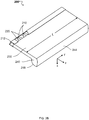
- a luminaire module 200 includes a mount 212 having a plurality of LEEs 210 distributed along a first surface of the mount 212.
- the mount with the LEEs 210 is disposed at a first (e.g., upper) edge 231 of a light guide 230.
- first e.g., upper
- the positive z-direction is referred to as the "forward” direction and the negative z-direction is the "backward" direction.
- Sections through the luminaire module 200 parallel to the x-z plane are referred to as the "cross-section" or “cross-sectional plane" of the luminaire module.
- luminaire module 200 extends along the y-direction, so this direction is referred to as the "longitudinal" direction of the luminaire module.
- Implementations of luminaire modules can have a plane of symmetry parallel to the y-z plane, be curved or otherwise shaped. This is referred to as the "symmetry plane" of the luminaire module.
- Multiple LEEs 210 are disposed on the first surface of the mount 212, although only one of the multiple LEEs 210 is shown in Figure 2A .
- the plurality of LEEs 210 can include multiple white LEDs.
- the LEEs 210 are optically coupled with one or more optical couplers 220 (only one of which is shown in Figure 2A ).
- An optical extractor 240 is disposed at second (e.g., lower) edge 232 of light guide 230.
- Mount 212, light guide 230, and optical extractor 240 extend a length L along the y-direction, so that the luminaire module is an elongated luminaire module with an elongation of L that may be about parallel to a wall of a room (e.g., a ceiling of the room).
- L can vary as desired.
- L is in a range from about 1 cm to about 200 cm (e.g., 20 cm or more, 30 cm or more, 40 cm or more, 50 cm or more, 60 cm or more, 70 cm or more, 80 cm or more, 100 cm or more, 125 cm or more, or, 150 cm or more).
- the number of LEEs 210 on the mount 212 will generally depend, inter alia , on the length L, where more LEEs are used for longer luminaire modules.
- the plurality of LEEs 210 can include between 10 and 1,000 LEEs (e.g., about 50 LEEs, about 100 LEEs, about 200 LEEs, about 500 LEEs).
- the density of LEEs (e.g., number of LEEs per unit length) will also depend on the nominal power of the LEEs and illuminance desired from the luminaire module. For example, a relatively high density of LEEs can be used in applications where high illuminance is desired or where low power LEEs are used.
- the luminaire module 200 has LEE density along its length of 0.1 LEE per centimeter or more (e.g., 0.2 per centimeter or more, 0.5 per centimeter or more, 1 per centimeter or more, 2 per centimeter or more).
- the density of LEEs may also be based on a desired amount of mixing of light emitted by the multiple LEEs.
- LEEs can be evenly spaced along the length, L, of the luminaire module.
- a heat-sink 205 can be attached to the mount 212 to extract heat emitted by the plurality of LEEs 210.
- the heat-sink 205 can be disposed on a surface of the mount 212 opposing the side of the mount 212 on which the LEEs 210 are disposed.
- the luminaire module 200 can include one or multiple types of LEEs, for example one or more subsets of LEEs in which each subset can have different color or color temperature.
- Optical coupler 220 includes one or more solid pieces of transparent optical material (e.g., a glass material or a transparent organic plastic, such as polycarbonate or acrylic) having surfaces 221 and 222 positioned to reflect light from the LEEs 210 towards the light guide 230.
- surfaces 221 and 222 are shaped to collect and at least partially collimate light emitted from the LEEs.
- surfaces 221 and 222 can be straight or curved. Examples of curved surfaces include surfaces having a constant radius of curvature, parabolic or hyperbolic shapes.
- surfaces 221 and 222 are coated with a highly reflective material (e.g., a reflective metal, such as aluminum or silver), to provide a highly reflective optical interface.
- a highly reflective material e.g., a reflective metal, such as aluminum or silver
- the cross-sectional profile of optical coupler 220 can be uniform along the length L of luminaire module 200. Alternatively, the cross-sectional profile can vary. For example, surfaces 221 and/or 222 can be curved out of the x-z plane.
- the exit aperture of the optical coupler 220 adjacent upper edge of light guide 231 is optically coupled to edge 231 to facilitate efficient coupling of light from the optical coupler 220 into light guide 230.
- the surfaces of a solid optical coupler 220 and a solid light guide 230 can be attached using a material that substantially matches the refractive index of the material forming the optical coupler 220 or light guide 230 or both (e.g., refractive indices across the interface are different by 2% or less.)
- the optical coupler 220 can be affixed to light guide 230 using an index matching fluid, grease, or adhesive.
- optical coupler 220 is fused to light guide 230 or they are integrally formed from a single piece of material (e.g., coupler and light guide may be monolithic and may be made of a solid transparent optical material).
- Light guide 230 is formed from a piece of transparent material (e.g., glass material such as BK7, fused silica or quartz glass, or a transparent organic plastic, such as polycarbonate or acrylic) that can be the same or different from the material forming optical couplers 220.
- Light guide 230 extends length L in the y-direction, has a uniform thickness T in the x-direction, and a uniform depth D in the z-direction.
- the dimensions D and T are generally selected based on the desired optical properties of the light guide (e.g., which spatial modes are supported) and/or the direct/indirect intensity distribution.
- light coupled into the light guide 230 from optical coupler 220 (with an angular range 125) reflects off the planar surfaces of the light guide by TIR and spatially mixes within the light guide.
- the mixing can help achieve illuminance and/or color uniformity, along the y-axis, at the distal portion of the light guide 232 at optical extractor 240.
- the depth, D, of light guide 230 can be selected to achieve adequate uniformity at the exit aperture (i.e., at end 232) of the light guide.
- D is in a range from about 1 cm to about 20 cm (e.g., 2 cm or more, 4 cm or more, 6 cm or more, 8 cm or more, 10 cm or more, 12 cm or more).
- optical couplers 220 are designed to restrict the angular range of light entering the light guide 230 (e.g., to within +/-40 degrees) so that at least a substantial amount of the light (e.g., 95% or more of the light) is optically coupled into spatial modes in the light guide 230 that undergoes TIR at the planar surfaces.
- Light guide 230 can have a uniform thickness T, which is the distance separating two planar opposing surfaces of the light guide.
- T is sufficiently large so the light guide has an aperture at first (e.g., upper) surface 231 sufficiently large to approximately match (or exceed) the exit aperture of optical coupler 220.
- T is in a range from about 0.05 cm to about 2 cm (e.g., about 0.1 cm or more, about 0.2 cm or more, about 0.5 cm or more, about 0.8 cm or more, about 1 cm or more, about 1.5 cm or more).
- a narrow light guide also provides a narrow exit aperture. As such light emitted from the light guide can be considered to resemble the light emitted from a one-dimensional linear source light, also referred to as an elongate virtual filament.
- optical coupler 220 and light guide 230 are formed from solid pieces of transparent optical material, hollow structures are also possible.
- the optical coupler 220 or the light guide 230 or both may be hollow with reflective inner surfaces rather than being solid. As such material cost can be reduced and absorption in the light guide avoided.
- specular reflective materials may be suitable for this purpose including materials such as 3M VikuitiTM or Miro IVTM sheet from Alanod Corporation where greater than 90% of the incident light would be efficiently guided to the optical extractor.
- Optical extractor 240 is also composed of a solid piece of transparent optical material (e.g., a glass material or a transparent organic plastic, such as polycarbonate or acrylic) that can be the same as or different from the material forming light guide 230.
- the optical extractor 240 includes redirecting (e.g., flat) surfaces 242 and 244 and curved surfaces 246 and 248.
- the flat surfaces 242 and 244 represent first and second portions of a redirecting surface 243, while the curved surfaces 246 and 248 represent first and second output surfaces of the luminaire module 200.
- Surfaces 242 and 244 are coated with a reflective material (e.g., a highly reflective metal, such as aluminum or silver) over which a protective coating may be disposed.
- a reflective material e.g., a highly reflective metal, such as aluminum or silver
- the material forming such a coating may reflect about 95% or more of light incident thereon at appropriate (e.g., visible) wavelengths.
- surfaces 242 and 244 provide a highly reflective optical interface for light having the angular range 125 entering an input end of the optical extractor 232' from light guide 230.
- the surfaces 242 and 244 include portions that are transparent to the light entering at the input end 232' of the optical extractor 240.
- these portions can be uncoated regions (e.g., partially silvered regions) or discontinuities (e.g., slots, slits, apertures) of the surfaces 242 and 244.
- some light is transmitted in the forward direction (along the z-axis) through surfaces 242 and 244 of the optical extractor 240 in an output angular range 125'.
- the light transmitted in the output angular range 125' is refracted.
- the redirecting surface 243 acts as a beam splitter rather than a mirror, and transmits in the output angular range 125' a desired portion of incident light, while reflecting the remaining light in angular ranges 138 and 138'.
- an included angle e.g., the smallest included angle between the surfaces 244 and 242
- the included angle can be relatively small (e.g., from 30° to 60°).
- the included angle is in a range from 60° to 120° (e.g., about 90°).
- the included angle can also be relatively large (e.g., in a range from 120° to 150° or more).
- the output surfaces 246, 248 of the optical extractor 240 are curved with a constant radius of curvature that is the same for both.
- the output surfaces 246, 248 may have optical power (e.g., may focus or defocus light.)
- luminaire module 200 has a plane of symmetry intersecting apex 241 parallel to the y-z plane.
- optical extractor 240 adjacent to the lower edge 232 of light guide 230 is optically coupled to edge 232.
- optical extractor 240 can be affixed to light guide 230 using an index matching fluid, grease, or adhesive.
- optical extractor 240 is fused to light guide 230 or they are integrally formed from a single piece of material.
- the emission spectrum of the luminaire module 200 corresponds to the emission spectrum of the LEEs 210.
- a wavelength-conversion material may be positioned in the luminaire module, for example remote from the LEEs, so that the wavelength spectrum of the luminaire module is dependent both on the emission spectrum of the LEEs and the composition of the wavelength-conversion material.
- a wavelength-conversion material can be placed in a variety of different locations in luminaire module 200.
- a wavelength-conversion material may be disposed proximate the LEEs 210, adjacent surfaces 242 and 244 of optical extractor 240, on the exit surfaces 246 and 248 of optical extractor 240, and/or at other locations.
- the layer of wavelength-conversion material may be attached to light guide 230 held in place via a suitable support structure (not illustrated), disposed within the extractor (also not illustrated) or otherwise arranged, for example.
- Wavelength-conversion material that is disposed within the extractor may be configured as a shell or other object and disposed within a notional area that is circumscribed between R/n and R*(I+n 2 ) (-1/2) , where R is the radius of curvature of the light-exit surfaces (246 and 248 in Figure 2A ) of the extractor 240 and n is the index of refraction of the portion of the extractor that is opposite of the wavelength-conversion material as viewed from the reflective surfaces (242 and 244 in Figure 2A ).
- the support structure may be a transparent self-supporting structure.
- the wavelength-conversion material diffuses light as it converts the wavelengths, provides mixing of the light and can help uniformly illuminate a surface of the ambient environment.
- the redirecting surface 242 provides light having an angular distribution 138 towards the output surface 246, the second portion of the redirecting surface 244 provides light having an angular distribution 138' towards the output surface 246.
- the redirected light exits optical extractor through output surfaces 246 and 248.
- the output surfaces 246 and 248 have optical power, to redirect the light exiting the optical extractor 240 in angular ranges 142 and 142', respectively.
- optical extractor 240 may be configured to emit light upwards (i.e., towards the plane intersecting the LEEs and parallel to the x-y plane), downwards (i.e., away from that plane) or both upwards and downwards.
- the direction of light exiting the luminaire module through surfaces 246 and 248 depends on the divergence of the light exiting light guide 230 and the orientation of surfaces 242 and 244.
- Surfaces 242 and 244 may be oriented so that little or no light from light guide 230 is output by optical extractor 240 in certain directions.
- the luminaire module 200 is attached to a ceiling of a room (e.g., the forward direction is towards the floor) such configurations can help avoid glare and an appearance of non-uniform illuminance.
- the light intensity distribution provided by luminaire module 200 reflects the symmetry of the luminaire module's structure about the y-z plane.
- light output in angular range 142' corresponds to the first output lobe 145a of the far-field light intensity distribution 101
- light output in angular range 142 corresponds to the second output lobe 145b of the far-field light intensity distribution 101
- light output (leaked) in angular range 125' corresponds to the third output lobe 145c of the far-field light intensity distribution 101.
- an intensity profile of luminaire module 200 will depend on the configuration of the optical coupler 220, the light guide 230 and the optical extractor 240.
- the interplay between the shape of the optical coupler 220, the shape of the redirecting surface 243 of the optical extractor 240 and the shapes of the output surfaces 246, 248 of the optical extractor 240 can be used to control the angular width and prevalent direction (orientation) of the first 145a and second 145b output lobes in the far-field light intensity profile 101. Additionally, a ratio of an amount of light in the combination of first 145a and second 145b output lobes and light in the third output lobe 145c is controlled by reflectivity and transmissivity of the redirecting surfaces 242 and 244.
- 45% of light can be output in the output angular range 142' corresponding to the first output lobe 145a, 45% light can be output in the output angular range 142 corresponding to the second output lobe 145b, and 10% of light can be output in the output angular range 125' corresponding to the third output lobe 145c.
- the orientation of the output lobes 145a, 145b can be adjusted based on the included angle of the v-shaped groove 241 formed by the portions of the redirecting surface 242 and 244. For example, a first included angle results in a far-field light intensity distribution 101 with output lobes 145a, 145b located at relatively smaller angles compared to output lobes 145a, 145b of the far-field light intensity distribution 101 that results for a second included angle larger than the first angle. In this manner, light can be extracted from the luminaire module 200 in a more forward direction for the smaller of two included angles formed by the portions 242, 244 of the redirecting surface 243.
- surfaces 242 and 244 are depicted as planar surfaces, other shapes are also possible. For example, these surfaces can be curved or composite. Curved redirecting surfaces 242 and 244 can be used to narrow or widen the output lobes 145a, 145b. Depending of the divergence of the angular range 125 of the light that is received at the input end of the optical extractor 232', concave reflective surfaces 242, 244 can narrow the lobes 145a, 145b output by the optical extractor 240 (and illustrated in Figure 1B ), while convex reflective surfaces 242, 244 can widen the lobes 145a, 145b output by the optical extractor 240. As such, suitably configured redirecting surfaces 242, 244 may introduce convergence or divergence into the light. Such surfaces can have a constant radius of curvature, can be parabolic, hyperbolic, or have some other curvature.
- the geometry of the elements can be established using a variety of methods.
- the geometry can be established empirically.
- the geometry can be established using optical simulation software, such as LighttoolsTM, TraceproTM, FREDTM or ZemaxTM, for example.
- luminaire module 200 can be designed to output light into different output angular ranges 142, 142' from those shown in Figure 2A .
- illumination devices can output light into lobes 142a, 142b that have a different divergence or propagation direction than those shown in Figure 1B .
- the output lobes 145a, 145b can have a width of up to about 90° (e.g., 80° or less, 70° or less, 60° or less, 50° or less, 40° or less, 30° or less, 20° or less).
- the direction in which the output lobes 145a, 145b are oriented can also differ from the directions shown in Figure 1B .
- the "direction" refers to the direction at which a lobe is brightest.
- the output lobes 145a, 145b are oriented at approx. -130° and approximately +130°.
- output lobes 145a, 145b can be directed more towards the horizontal (e.g., at an angle in the ranges from -90° to -135°, such as at approx. -90°, approx. -100°, approx. -110°, approx. -120°, approx. -130°, and from +90° to +135°, such as at approx. +90°, approx. +100°, approx. +110°, approx. +120°, approx. +130°.
- luminaire modules can include other features useful for tailoring the intensity profile.
- luminaire modules can include an optically diffuse material that can diffuse light in a controlled manner to aid homogenizing the luminaire module's intensity profile.
- surfaces 242 and 244 can be roughened or a diffusely reflecting material, rather than a specular reflective material, can be coated on these surfaces. Accordingly, the optical interfaces at surfaces 242 and 244 can diffusely reflect light, scattering light into broader lobes than would be provided by similar structures utilizing specular reflection at these interfaces.
- these surfaces can include structure that facilitates various intensity distributions.
- surfaces 242 and 244 can each have multiple planar facets at differing orientations. Accordingly, each facet will reflect light into different directions.
- surfaces 242 and 244 can have structure thereon (e.g., structural features that scatter or diffract light).
- Surfaces 246 and 248 need not be surfaces having a constant radius of curvature.
- surfaces 246 and 248 can include portions having differing curvature and/or can have structure thereon (e.g., structural features that scatter or diffract light).
- a light scattering material can be disposed on surfaces 246 and 248 of optical extractor 240.
- optical extractor 240 is structured so that a negligible amount (e.g., less than 1%) of the light propagating within at least one plane (e.g., the x-z cross-sectional plane) that is reflected by surface 242 or 244 experiences TIR at light-exit surface 246 or 248.
- a so-called Weierstrass condition can avoid TIR.
- a Weierstrass condition is illustrated for a circular structure (i.e., a cross section through a cylinder or sphere) having a surface of radius R and a concentric notional circle having a radius R/n, where n is the refractive index of the structure.
- Any light ray that passes through the notional circle within the cross-sectional plane is incident on surface of the circular structure and has an angle of incidence less than the critical angle and will exit circular structure without experiencing TIR.
- Light rays propagating within spherical structure in the plane but not emanating from within notional surface can impinge on the surface of radius R at the critical angle or greater angles of incidence. Accordingly, such light may be subject to TIR and won't exit the circular structure.
- rays of p-polarized light that pass through a notional space circumscribed by an area with a radius of curvature that is smaller than R/(1+n 2 ) (-1/2) , which is smaller than R/n will be subject to small Fresnel reflection at the surface of radius R when exiting the circular structure.
- This condition may be referred to as Brewster geometry. Implementations may be configured accordingly.
- all or part of surfaces 242 and 244 may be located within a notional Weierstrass surface defined by surfaces 246 and 248.
- the portions of surfaces 242 and 244 that receive light exiting light guide 230 through end 232 can reside within this surface so that light within the x-z plane reflected from surfaces 244 and 246 exits through surfaces 246 and 248, respectively, without experiencing TIR.
- the luminaire module 200 is configured to output light into output angular ranges 142, 142' and optionally 125'.
- the light guide-based luminaire module 200 is modified to output light into a single output angular range 142'.
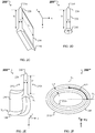
- Figure 2B illustrates an example of such light guide-based luminaire module 200* configured to output light on a single side of the light guide 230.
- the luminaire module 200* is referred to as a single-sided luminaire module.
- the single-sided luminaire module 200* is elongated along the y-axis like the luminaire module 200 shown in Figure 2A .
- the single-sided luminaire module 200* includes a mount 212 and LEEs 210 disposed on a surface of the mount 212 along the y-axis to emit light in a first angular range.
- the single-sided luminaire module 200* further includes an optical coupler 220 arranged and configured to redirect the light emitted by the LEEs 210 in the first angular range into a second angular range 125 that has a divergence smaller than the divergence of the first angular range at least in the x-z cross-section.
- the single-sided luminaire module 200* includes a light guide 230 to guide the light redirected by the optical coupler 220 in the second angular range 125 from a first end 231 of the light guide to a second end 232 of the light guide. Additionally, the single-sided luminaire module 200* includes a single-sided extractor (denoted 240') to receive the light guided by the light guide 230.
- the single-sided extractor 240' includes a redirecting surface 244 to redirect the light received from the light guide 230 into a third angular range 138' - like described for luminaire module 200 with reference to Figure 2A - and an output surface 248 to output the light redirected by the redirecting surface 244 in the third angular range 138' into a fourth angular range 142'.
- a light intensity profile of the single-sided luminaire module 200* is represented in Figure 1B as a single output lobe 145a.
- the single output lobe 145a corresponds to light output by the single-sided luminaire module 200* in the fourth angular range 142'.
- Figure 2C shows an embodiment 200' of the luminaire module 200 that also is elongated along an axis (e.g., y-axis) perpendicular to the forward direction (e.g., along the z-axis.)
- a length L of the light guide 230 along the elongated dimension of the luminaire module 200' can be 2', 4' or 8', for instance.
- a thickness T of the light guide 230 orthogonal to the elongated dimension L is chosen to be a fraction of the distance D traveled by the guided light from the receiving end to the opposing end of the light guide 230.
- T 0.05D, 0.1D or 0.2D
- light from multiple, point-like LEEs 210 - distributed along the elongated dimension L - that is edge-coupled into the light guide 230 at the receiving end can efficiently mix and become uniform (quasi-continuous) along the y-axis by the time it propagates to the opposing end.
- Figure 2D shows a luminaire module 200" that has (e.g., continuous or discrete) rotational symmetry about the forward direction (e.g., z-axis.)
- a diameter T of the light guide 230 is a fraction of the distance D traveled by the guided light from the receiving end to the opposing end of the light guide 230.
- FIGS 2E and 2F show a perspective view and a bottom view, respectively, of a luminaire module 200'" for which the light guide 230 has two opposing side surfaces 232a, 232b that form a closed cylinder shell of thickness T.
- the x-y cross-section of the cylinder shell formed by the opposing side surfaces 232a, 232b is oval.
- the x-y cross-section of the cylinder shell can be circular or can have other shapes.
- Some implementations of the example luminaire module 200"' may include a specular reflective coating on the side surface 232a of the light guide 230.
- T 0.05D, 0.1D or 0.2D
- light from multiple, point-like LEEs 210 - distributed around the z-axis along an elliptical path of length L - that is edge-coupled into the light guide 230 at the receiving end can efficiently mix and become uniform (quasi-continuous) along such an elliptical path by the time it propagates to the opposing end.
- the luminaire module 200 includes a light guide 230 to guide (translate) light from the exit aperture of the optical couplers 220 to the input end 231' of the optical extractor 240.
- Figure 2G illustrates an example of such "hollow" luminaire module 200-h that includes LEEs 210, one or more corresponding optical couplers 220 (like the luminaire module 200) and an optical extractor (simplified relative to the optical extractor 240 of the luminaire module 200) that uses only a redirecting surface 243 to extract - to the ambient environment - the light provided by the optical couplers 220.
- the hollow luminaire module 200-h is elongated along the y-axis like the luminaire module 200 shown in Figure 2A .
- the hollow luminaire module 200-h includes a mount 212 (having a normal along the z-axis) such that the LEEs 210 are disposed on a surface of the mount 212 along the y-axis to emit light in a first angular range along the z-axis.
- the optical couplers 220 are arranged and configured to redirect the light emitted by the LEEs 210 in the first angular range into a second angular range 125 that has a divergence smaller than the divergence of the first angular range at least in the x-z cross-section.
- the redirecting surface 243 is spaced apart from an exit aperture of the optical couplers 220 by a distance D and includes two reflecting surfaces arranged to form a v-groove with an apex pointing toward the optical couplers 220.
- the distance D is selected based on a divergence of the second angular range 225 and of a transverse dimension (along the x-axis) of the redirecting surface 243, such that all light provided by the optical couplers in the second angular range 225 impinges on the redirecting surface 243.
- the redirecting surface 243 redirects some of the light received from the optical couplers 220 into a third angular range 138' and another portion of the redirecting surface 243 redirects the remaining light received from the optical couplers 220 into a fourth angular range 138.
- the redirecting surface 243 is semitransparent. In this manner, a fraction of the light received from the optical couplers 220 in angular range 225 is transmitted (leaks) through the redirecting surface 243 in a fifth angular range 225'.
- a prevalent propagation direction for the fifth angular range 225' is in the forward direction (along the z-axis.)
- a light intensity profile of the hollow luminaire module 200-h can be represented similar to the one shown in Figure 1B as first 145a and second 145b output lobes, and optionally as an additional third output lobe 145c.
- the first output lobe 145a corresponds to light output by the hollow luminaire module 200-h in the third angular range 138'
- the second output lobe 145b corresponds to light output by the hollow luminaire module 200-h in the fourth angular range 138
- the third output lobe 145c corresponds to light output by the hollow luminaire module 200-h in the fifth angular range 225'.
- Figure 2H is a cross-section of an optical coupler 220-a that can be used in the luminaire modules 200, 200*, 200', 200", 200'" or 200-h, for example, to receive light emitted by a light source 210-a.
- the optical coupler 220-a is configured to redirect the received light along an optical axis 102-a of the optical coupler 220-a. It can be configured to do so using only TIR.
- the shape of the side surfaces of a compact sized optical coupler that can rely only on TIR is described in detail below.
- an emission direction 106-a of the light source 210-a - representing a prevalent propagation direction of the light emitted by the light source 210-a - is parallel to the z-axis; equivalently, an angle ⁇ between the emission direction 106-a and the z-axis is zero.
- the optical axis 102-a of the optical coupler 220-a is centered on an exit aperture 225-a of the optical coupler 220-a and also is parallel to the z-axis.
- the optical axis 102-a coincides with the optical axis of the luminaire module.
- a width of the light source 210-a along a direction orthogonal to the optical coupler' optical axis 102-a (e.g., along the x-axis) is 1-unit length.
- the light source 210-a can be an extended light source (e.g., emitting light uniformly from each surface element of the light source 210-a) or one or more LEEs 210 that are part of an LED die, for example.
- the LEEs 210 can include multiple (e.g., LED) emitters, such as an array of emitters in a single package, or an array of emitters disposed on a substrate having a normal 106-a.
- the light source 210-a is represented by segment OM, where the point O is the origin of a Cartesian coordinate system.
- the optical coupler 220-a includes one or more solid pieces of transparent material (e.g., glass or a transparent organic plastic, such as polycarbonate or acrylic).
- An input aperture of the optical coupler 220-a is optically coupled with the light source 210-a.
- a width of the input aperture matches the width of the light source 210-a along the x-axis normalized to 1-unit length like the value of the width of the light source 210-a.
- the exit aperture 225-a of the optical coupler 220-a is optically coupled to the input end of a light guide 230-a.
- the optical coupler 220-a and light guide 230-a can be coupled by using a material that substantially matches the refractive index of the material forming the optical coupler 220-a or the light guide 230-a, or both.
- the optical coupler 220-a can be affixed to the light guide 230-a using an index matching fluid, grease, or adhesive.
- the optical coupler 220-a is fused to the light guide 230-a or they are integrally formed from a single piece of material.
- redirected light output by the optical coupler 220-a through the exit aperture 225-a is guided by the light guide 230-a to an optical extractor coupled at an opposing end of the light guide 230-a.
- redirected light output by the optical coupler 220-a through the exit aperture 225-a is provided to an optical extractor spaced apart from the optical coupler 220-a by a distance D (not shown in Figure 2H ).
- the exit aperture 225-a is represented by segment NP.
- the optical coupler 220-a includes curved side surfaces 224-a, 224'-a that are shaped such the light emitted from any point of the light source 210-a is incident on the curved side surfaces 224-a, 224'-a at angles that exceed a critical angle ⁇ c.
- the angle ⁇ satisfies 0 ⁇ ⁇ ⁇ ⁇ C
- each of equations (1) and (2) describes a curve known as an equiangular spiral (also called a logarithmic spiral), which is a compact shape that can effectuate the TIR condition.
- the sectional profile of the curved side surface 224'-a given by equation (2) - and represented by curve OP - is the mirror inverse of the sectional profile of the curved side surface 224-a given by equation (1) - and represented by curve MN.
- the side surfaces can be shaped based on a notional critical angle that is slightly enlarged from the nominal critical angle associated with the nominal properties of the materials employed in the fabrication of the optical coupler.
- the curved side surfaces 224-a, 224'-a may be continuously rotationally symmetric about the optical axis 102-a of the optical coupler 220-a (like in the luminaire module 200" illustrated in Figure 2D ) or have translational symmetry along an axis perpendicular to the sectional plane of Figure 2H , e.g., along the y-axis, (like in the luminaire modules 200, 200* or 200' illustrated in Figures 2A-2C .)
- Equations (1) and (2) can be used to determine a length (along the optical axis 102-a, e.g., the z-axis) of the optical coupler 220-a and a width (along the x-axis) of the exit aperture 225-a.
- the length of the optical coupler 220-a is given by a distance between the optical source 210-a (segment OM) and the exit aperture 225-a (segment NP). Additionally, the width of the exit aperture 225-a is equivalent to a length of segment NP.
- the length of the optical coupler 220-a and the width of the exit aperture 225-a increase with decreasing refractive index.
- the length of the optical coupler 220-a is about 1.3 unit-lengths
- the width of the exit aperture 225-a is about 1.8 unit-lengths.
- Luminaire modules like the ones described in this section - in which source light injection is parallel to the device's optical axis - can be modified to obtain luminaire modules in which source light injection is non-parallel to the devices' optical axis, as described in the following section.
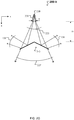
- Figure 3 shows examples of illumination devices 200-b, 200-c, 200-d and 200e in which source light injection is non-parallel to an optical axis of the devices.
- Figure 3 also illustrates - for comparison - an example of illumination device 200-a, similar to the luminaire module 200 or 200' described above in connection with respective Figures 2A or 2C , in which source light injection is parallel to an optical axis of the device.
- the optical axis of each of the devices 200-a, 200-b, 200-c, 200-d and 200e is the z-axis.
- Each illumination device 200-j where j is in the set ⁇ a, b, c, d, e ⁇ , includes a light source 210-j and one or more optical couplers 220-j.
- the light source 210-j is oriented relative the optical axis of the illumination device 200-j such that an emission direction 106-j of the light source 210-j is different for each illumination device 200-j.
- the emission direction 106-j represents a prevalent propagation direction of the light emitted by the light source 210-j.
- the light source 210-j is elongated orthogonally relative the optical axis of the illumination device 200-j, e.g., with a longitudinal dimension L along the y-axis, as illustrated in Figures 2A or 2C .
- L can be 1', 2' or 4', for instance.
- the illumination device can have another elongated configuration, as illustrated in Figures 2E-2F .
- a single optical coupler 220-j also is elongated in the same manner as the light source 210-j, e.g., along the y-axis, or multiple optical couplers 220-j are distributed along the longitudinal dimension L of the light source 210-j.
- the light source 210-j can have a non-elongated configuration, e.g., with rotational symmetry around the z-axis, as illustrated in Figure 2D .
- the optical couplers 220-j redirect, using TIR only, the light received from the light source 210-j under the emission direction 106-j and provides the redirected light along the optical axis (e.g., the z-axis) of the illumination device 200-j.
- the optical couplers 220-j are referred to as TIR optical couplers 220-j.
- the illumination device 200-j also includes a light guide 230-j and an optical extractor 240-j, where j is in the set ⁇ a, b, c, d, e ⁇ .
- the light guide 230-j and the extractor 240-j also are elongated along the y-axis with the longitudinal dimension L, as illustrated in Figures 2A or 2C .
- the light guide 230-j guides the light - provided by the TIR optical couplers 220-j at an input end of the light guide 230-j - from the input end to an opposing end along the optical axis of the illumination device 200-j, e.g., the z-axis.
- the optical extractor 240-j is coupled with the light guide 230-j at the opposing end to receive the guided light.
- the optical extractor 240-j outputs most of the light received from the light guide 230-j to an ambient environment along a first backward direction that has a component orthogonal to the optical axis of the illumination device 200-j and as second backward direction that has a component (i) orthogonal to the optical axis of the illumination device 200-j and (ii) opposing the orthogonal component of the first backward direction.
- the light output by the optical extractor 240-j along the first backward direction corresponds to the first output lobe 145a of the far field intensity profile shown in Figure 1B
- the light output by the optical extractor 240-j along the second backward direction corresponds to the second output lobe 145b.
- the optical extractor 240-j transmits a fraction of the light received from the light guide 230-j to the ambient environment along the forward direction.
- the light output by the optical extractor 240-j in the forward direction corresponds to the third output lobe 145c.
- the emission direction 106-a is parallel to the optical axis of the illumination device 200-a.
- Such parallel source light injection associated with a combination of light source 210-a and TIR optical coupler 220-a of the illumination device 200-a is described above in connection with Figure 2H .
- the emission direction 106-a is oblique to the optical axis of the illumination device 200-j.
- the emission direction 106-e is orthogonal to the optical axis of the illumination device 200-e.
- Example 2 Oblique light injection under an angle less than a critical angle
- Figure 4 is a cross-section of a TIR optical coupler 220-b used in the illumination device 200-b to receive light emitted by a light source 210-b and to redirect the received light along an optical axis 102-b of the optical coupler 220-b using only TIR.
- an emission direction 106-b of the light source 210-b - representing a prevalent propagation direction of the light emitted by the light source 210-b - forms a tilt angle ⁇ with the optical axis 102-b.
- the optical axis 102-b of the optical coupler 220-b (which coincides with an optical axis of the illumination device 200-b) is centered on an exit aperture 225-b of the optical coupler 220-b and is parallel to the z-axis.
- the light source 210-b is represented by segment OM that has a length of 1-unit length, where the point O is the origin of a Cartesian coordinate system.
- An input aperture of the optical coupler 220-b is optically coupled with the light source 210-b. In this example, a width and orientation of the input aperture matches respective width and orientation of the light source 210-b.
- the exit aperture 225-b of the optical coupler 220-b is optically coupled to the input end of a light guide 230-b as described above in connection with Figure 3 .
- the optical coupler 220-b can be part of a luminaire module without light guide, similar to the luminaire module 200-h, redirected light output by the optical coupler 220-b through the exit aperture 225-b is provided to an optical extractor spaced apart from the optical coupler 220-b by a distance D (not shown in Figure 4 ).
- the exit aperture 225-b is represented by segment NP.
- the optical coupler 220-b includes a curved side surface 224-b and a composite side surface 223-b that are shaped such the light emitted from any point of the light source 210-b is incident on the curved side surface 224-a and the composite side surface 223-b at angles that are at or exceed the critical angle ⁇ C .
- all light emitted by the light source 210-b is redirected by the optical coupler 220-b via TIR towards the exit aperture 225-b.
- the composite side surface 223-b includes a curved portion 224'-b and a flat portion 226-b.
- the flat portion 226-b is aligned with the optical axis 102-b.
- the curved side surface 224-b is represented by curve MM
- the curved portion 224'-b of the composite side surface 223-b is represented by curve OQ, where the point O is the origin of the Cartesian coordinate system
- the flat portion 226-b of the composite side surface 223-b is represented by segment QP parallel with the z-axis.
- the point Q of the composite side surface 223-b separates the curved portion 224'-b from the flat portion 226-b.
- the point Q - with Cartesian coordinates (x Q , z Q ) - also is part of the flat portion 226-b of the composite side surface 223-b.
- any point R 3 of the flat portion 226-b of the composite side surface 223-b has an x-coordinate equal to x Q - the x-coordinate of the point Q.
- the sectional profile of the composite side surface 223-b including the curved portion 224'-b given by equation (2) - and represented by curve OQ - and the flat portion 226-b - and represented by segment QP - is not the mirror inverse of the sectional profile of the curved side surface 224-b given by equation (1) - and represented by curve MN.
- the curved portion OQ 224'-b is a mirror inverse of only a portion of the curved portion 224-b with respect to 106-b.
- the curved side surface 224-b and the composite side surface 223-b may have translational symmetry along an axis perpendicular to the sectional plane of Figure 4 , e.g., along the y-axis, (like in the luminaire modules 200, 200* or 200' illustrated in Figures 2A-2C .)
- the above calculations can be used to determine a length (along the optical axis 102-b, e.g., the z-axis) of the optical coupler 220-b and a width (along the x-axis) of the exit aperture 225-b.
- the length of the optical coupler 220-b is given by a maximum distance between a point of the curved side surface 224-b (curve MN) and the exit aperture 225-b (segment NP). Additionally, the width of the exit aperture 225-b is equivalent to a length of segment NP.
- the length of the optical coupler 220-b and the width of the exit aperture 225-b increase with decreasing refractive index.
- n 1.5
- the length of the optical coupler 220-b is about 2.2 unit-lengths
- the width of the exit aperture 225-b is about 2.2 unit-lengths.
- FIGS 5-7 are respective cross-sections of TIR optical couplers 220-j used in the illumination devices 200-j, where j is in the set ⁇ c, d, e ⁇ , to receive light emitted by a light source 210-j and to redirect the received light along an optical axis 102-j of the optical coupler 220-j using only TIR.
- an emission direction 106-j of the light source 210-j - representing a prevalent propagation direction of the light emitted by the light source 210-j - forms a tilt angle ⁇ j with the optical axis 102-j.
- the optical axis 102-j of the optical coupler 220-j (which coincides with an optical axis of the illumination device 200-j) is centered on an exit aperture 225-j of the optical coupler 220-j and is parallel to the z-axis.
- a transparent, solid material e.g., glass or a transparent organic plastic, such as polycarbonate or acrylic
- a transparent, solid material e.g., glass or a transparent organic plastic, such as polycarbonate or acrylic
- a transparent, solid material e.g., glass or a transparent organic plastic, such as polycarbonate or acrylic
- the light source 210-j where j is in the set ⁇ c, d, e ⁇ , can be implemented by tilting the light source 210-a - described above in connection with Figure 2H - by the tilt angle ⁇ j ⁇ ⁇ C around an axis orthogonal on both the optical axis 102-j and the emission direction 106-j, e.g., around the y-axis.
- ⁇ c ⁇ C in the example illustrated in Figure 5
- ⁇ d 2 ⁇ C in the example illustrated in Figure 6
- ⁇ e 90° in the example illustrated in Figure 7 .
- the light source 210-j is represented by segment OM that has a length of 1-unit length, where the point O is the origin of a Cartesian coordinate system.
- An input aperture of the optical coupler 220-j is optically coupled with the light source 210-j.
- a width and orientation of the input aperture matches respective width and orientation of the light source 210-j.
- the exit aperture 225-j of the optical coupler 220-j is optically coupled to the input end of a light guide 230-j as described above in connection with Figure 3 .
- the optical coupler 220-j is part of a luminaire module without light guide, similar to the luminaire module 200-h, redirected light output by the optical coupler 220-j through the exit aperture 225-j is provided to an optical extractor spaced apart from the optical coupler 220-j by a distance D (not shown in Figures 5-7 ).
- the exit apertures 225-j are represented by corresponding segments NP.
- the optical coupler 220-j includes a curved side surface 224-j and a flat side surface 226-j that are shaped such the light emitted from any point of the light source 210-j is incident on the curved side surface 224-j and the flat side surface 226-j at angles that exceed the critical angle ⁇ C .
- the flat side surface 226-j is aligned with the optical axis 102-j. For the examples illustrated in Figures 5-7 , all light emitted by the light source 210-j is redirected by the optical coupler 220-j via TIR towards the exit aperture 225-j.
- the curved side surface 224-j is represented by curve MN and the flat side surface 226-j is represented by segment OP parallel with the z-axis, where the point O is the origin of the Cartesian coordinate system.
- any point R 1 of the curved side surface 224-j, where j is in the set ⁇ c, d, e ⁇ , - for which a segment OR 1 is inclined by an angle ⁇ relative to the segment OM (which in turn is tilted from the x-axis by the tilt angle ⁇ j) - is separated from the point O of the light source 210-j by a distance OR 1 ( ⁇ ) given by Equation (1).
- the angle ⁇ satisfies 0 ⁇ ⁇ ⁇ ⁇ C + ⁇ j.
- the tilt angle ⁇ e 90°
- the angle ⁇ satisfies 0 ⁇ ⁇ ⁇ ⁇ C + 90°
- any point R 3 of the flat side surface 226-j, where j is in the set ⁇ c, d, e ⁇ , has an x-coordinate equal to x O 0 - the x-coordinate of the origin point O.
- the sectional profile of the flat side surface 226-j - and represented by segment OP - is not the mirror inverse of the sectional profile of the curved side surface 224-j given by equation (1) - and represented by curve MN.
- the curved side surface 224-b and the composite side surface 223-b may have translational symmetry along an axis perpendicular to the sectional planes shown in Figures 5-7 , e.g., along the y-axis, (like in the luminaire modules 200, 200* or 200' illustrated in Figures 2A-2C .)
- the above calculations can be used to determine a length (along the optical axis 102-j, e.g., the z-axis) of the optical coupler 220-j and a width (along the x-axis) of the exit aperture 225-j, where j is in the set ⁇ c, d, e ⁇ .
- the length of the optical coupler 220-j is given by a maximum distance between a point of the curved side surface 224-j (curve MN) and the exit aperture 225-j (segment NP). Additionally, the width of the exit aperture 225-j is equivalent to a length of segment NP.
- the length of the optical coupler 220-j and the width of the exit aperture 225-j increase with decreasing refractive index.
- the length of the optical coupler 220-c is about 3.3 unit-lengths
- the width of the exit aperture 225-c is about 2.8 unit-lengths.
- the length of the optical coupler 220-d is about 5.8 unit-lengths
- the width of the exit aperture 225-d is about 5.2 unit-lengths.
- the length of the optical coupler 220-e is about 6.9 unit-lengths, and the width of the exit aperture 225-e is about 5.8 unit-lengths.
- Figure 8 shows a graph 800 that summarizes results of calculations described above in connection with Figures 2H , 4 , 5 , 6 and 7 .
- the graph 800 represents the determined widths (along the x-axis) of the exit apertures 225-j, where j is in the set ⁇ c, d, e ⁇ , of optical couplers 220-j used, for example, in the illumination devices 200-j illustrated in Figure 3 .
- Figure 3 illustrates embodiments of illumination devices 200-j, where j is in the set ⁇ a, b, c, d, e ⁇ , with a coupler 220-j and light source 210-j arrangements that can provide different locations and orientations for the LEEs of the light source. Such different arrangements may be exploited for thermal purposes, direct contact coupling, resilience to placement tolerances between LEEs and coupler 220-j/light guide 230-j and/or other aspects, for example.
- the LEEs of the light source 210-j may be placed on a substrate or directly on the coupler 220-j, or the light guide 230-j, for example.
- the coupler 220-j and the light guide 230-j can be integrally formed and as such considered one component which is referred to herein as coupler or light guide as the case may be.
- An emission direction 106-j of the light source 210-j can be oriented parallel (like in Figures 2H and 3 ), perpendicular (like in Figures 3 and 7 ) to the optical axis 102-j of the optical coupler 220-j or at an oblique angle (like in Figures 3-6 .)
- a corner of the optical coupler 220-j, where j is in the set ⁇ b, c, d, e ⁇ , or the light guide 230-j may have a beveled flat edge for abutting flat LEEs or an edge with suitable indentations for receiving packaged LEEs with dome lenses, for example.
- An immersion substance such as silicone or other curable or non-curable immersion substance may be applied to reduce air gaps between LEEs and the coupler 220-j/light guide 230
- a coupler 220-j can be created with either a solid cross section or a hollow metallic reflector cross section that can intercept the rays of light from the LEEs of the light source 210-j and introduce them into the elongated light guide 230-j such that their angular range at the junction between the coupler 220-j and the light guide 230-j is such that substantially all of the light will propagate through the light guide 230-j via total internal reflection until it reaches the extractor 240-j.
- a hollow coupler may have a shape different from a solid coupler 220-j. The efficiency of the disclosed technologies relies on the relative size of the light source 210-j and the dimensions of the coupler 220-j.
Claims (15)
- Beleuchtungsvorrichtung (200-b; 200-c; 200-d), umfassend:eine Lichtquelle (210-b; 210-c; 210-d), die dafür konfiguriert ist, im Betrieb Licht in einem Emissionswinkelbereich zu emittieren, wobei eine vorherrschende Fortpflanzungsrichtung des emittierten Lichts (106-b; 106-c; 106-d) im Emissionswinkelbereich von einer Richtung einer optischen Achse (102-c) der Beleuchtungsvorrichtung verschieden ist; undeinen Optokoppler (220-b; 220-c; 220-d), der ein transparentes Material umfasst, wobei der Optokoppler eine Eintrittsöffnung, die in einer ersten Ebene angeordnet ist, eine Austrittsöffnung (225-b; 225-c; 225-d), die in einer zweiten Ebene angeordnet ist, wobei die zweite Ebene die erste Ebene in einem spitzen Winkel schneidet, und eine erste Seitenfläche (224-b; 224-c; 224-d) und eine zweite Seitenfläche (223-b; 226-c; 226-d), die zwischen der Eintrittsöffnung und der Austrittsöffnung (225-b; 225-c; 225-d) angeordnet sind, aufweist, wobei die zweite Ebene senkrecht zur optischen Achse (102-c) der Beleuchtungsvorrichtung ausgerichtet ist,wobei der Optokoppler (220-b; 220-c; 220-d) durch die Eintrittsöffnung von der Lichtquelle (210-b; 210-c; 210-d) das Licht empfängt, das im Emissionswinkelbereich emittiert wird;wobei die erste Seitenfläche (224-b; 224-c; 224-d) und die zweite Seitenfläche (223-b; 226-c; 226-d) das empfangene Licht über eine interne Totalreflexion (TIR) zur Austrittsöffnung (225-b; 225-c; 225-d) umlenken,wobei die zweite Seitenfläche (223-b; 226-c; 226-d) einen flachen Abschnitt umfasst, der der Austrittsöffnung (225-b; 225-c; 225-d) benachbart und entlang der optischen Achse (102-c) der Beleuchtungsvorrichtung (200-b; 200-c; 200-d) ausgerichtet ist und wobei die erste Seitenfläche (224-b; 224-c; 224-d) einen gekrümmten Abschnitt beinhaltet, undwobei das umgelenkte Licht durch die Austrittsöffnung in einem umgelenkten Winkelbereich ausgegeben wird,wobei die Beleuchtungsvorrichtung ferner umfasst:einen Lichtleiter (230-b; 230-c; 230-d), der ein empfangendes Ende und ein gegenüberliegendes Ende umfasst, die entlang der optischen Achse (102-c) der Beleuchtungsvorrichtung (200-b; 200-c; 200-d) angeordnet sind, wobei das empfangende Ende so eingerichtet ist, dass es das vom Optokoppler (220-b; 220-c; 220-d) ausgegebene Licht empfängt, wobei der Lichtleiter (230-b; 230-c; 230-d) dafür konfiguriert ist, das am empfangenden Ende empfangene Licht in einer Vorwärtsrichtung zum gegenüberliegenden Ende zu leiten; undeinen optischen Extraktor (220-b; 220-c; 220-d), der sich am gegenüberliegenden Ende befindet und dafür konfiguriert ist, das geleitete Licht in eine umliegende Umgebung als Ausgabelicht auszugeben.
- Beleuchtungsvorrichtung nach Anspruch 1, wobei eine numerische Apertur des Lichtleiters (230-b; 230-c; 230-d) derart beschaffen ist, dass das vom Optokoppler (220-b; 220-c; 220-d) im umgelenkten Winkelbereich empfangene Licht über TIR durch den Lichtleiter geleitet werden kann.
- Beleuchtungsvorrichtung nach Anspruch 1 oder 2, wobei der optische Extraktor (240-b; 240-c; 240-d) mindestens eine Umlenkfläche (243; 242; 244) aufweist, wobei die mindestens eine Umlenkfläche (243) des optischen Extraktors (240-b; 240-c; 240-d) so eingerichtet und geformt ist, dass sie mindestens einen Teil des geleiteten Lichts in eine Richtung reflektiert, die eine zur Vorwärtsrichtung orthogonale Komponente aufweist.
- Beleuchtungsvorrichtung nach Anspruch 1 oder 2, wobei der optische Extraktor (230-b; 230-c; 230-d) eine erste Umlenkfläche (242), die so eingerichtet und geformt ist, dass sie mindestens einen Teil des geleiteten Lichts in eine Richtung reflektiert, die eine zur Vorwärtsrichtung orthogonale Komponente aufweist, und eine zweite Umlenkfläche (244) aufweist, die so eingerichtet und geformt ist, dass sie mindestens einen Teil des geleiteten Lichts in eine zweite Richtung reflektiert, die eine zur Vorwärtsrichtung orthogonale und zur orthogonalen Komponente der ersten Richtung antiparallele Komponente aufweist.
- Beleuchtungsvorrichtung nach Anspruch 1, wobei der optische Extraktor auf der optischen Achse der Beleuchtungsvorrichtung angeordnet und von der Austrittsöffnung des Optokopplers durch einen Trennabstand beabstandet ist,
wobei eine Kombination (i) des Trennabstands und (ii) der numerischen Apertur des optischen Extraktors so beschaffen ist, dass das gesamte vom Optokoppler ausgegebene Licht auf den optischen Extraktor auftrifft, und wobei der optische Extraktor dafür konfiguriert ist, das darauf auftreffende Licht als Ausgabelicht in eine umliegende Umgebung in rückwärtigen Richtungen auszugeben, die einer vorherrschenden Fortpflanzungsrichtung des vom Optokoppler ausgegebenen Lichts entgegengerichtet sind. - Beleuchtungsvorrichtung nach Anspruch 5, wobei der optische Extraktor mindestens eine Umlenkfläche aufweist, wobei die mindestens eine Umlenkfläche des optischen Extraktors so eingerichtet und geformt ist, dass sie mindestens einen Teil des darauf auftreffenden Lichts in einer rückwärtigen Richtung reflektiert, die eine zur vorherrschenden Fortpflanzungsrichtung des vom Optokoppler ausgegebenen Lichts orthogonale Komponente aufweist.
- Beleuchtungsvorrichtung nach Anspruch 5, wobei der optische Extraktor eine erste Umlenkfläche, die so eingerichtet und geformt ist, dass sie mindestens einen Teil des darauf auftreffenden Lichts in eine erste Richtung reflektiert, die eine zur vorherrschenden Fortpflanzungsrichtung des vom Optokoppler ausgegebenen Lichts orthogonale Komponente aufweist, und eine zweite Umlenkfläche aufweist, die so eingerichtet und geformt ist, dass sie mindestens einen Teil des darauf auftreffenden Lichts in eine zweite Richtung reflektiert, die eine zur vorherrschenden Fortpflanzungsrichtung des vom Optokoppler ausgegebenen Lichts orthogonale und zur orthogonalen Komponente der ersten Richtung antiparallele Komponente aufweist.
- Beleuchtungsvorrichtung nach Anspruch 1, wobei der spitze Winkel gleich oder größer als ein kritischer TIR-Winkel ist.
- Beleuchtungsvorrichtung nach Anspruch 8, wobei die erste Seitenfläche (224-b; 224-c; 224-d) eine logarithmische Spirale ist, die vom spitzen Winkel und dem kritischen TIR-Winkel abhängt.
- Beleuchtungsvorrichtung nach Anspruch 9, wobei die logarithmische Spirale nach Gleichung (1) berechnet wird.
- Beleuchtungsvorrichtung nach Anspruch 1, wobei jede von der ersten Seitenfläche (224-b; 224-c; 224-d) und der zweiten Seitenfläche (223-b; 226-c; 226-d) sich in einer Richtung erstreckt, die zur optischen Achse (102-c) orthogonal ist.
- Beleuchtungsvorrichtung nach Anspruch 1, wobei die erste Seitenfläche (224-b; 224-c; 224-d) sich entlang einer Richtung erstreckt, die zur optischen Achse (102-c) orthogonal ist.
- Beleuchtungsvorrichtung nach Anspruch 1, wobei die zweite Seitenfläche (223-b; 226-c; 226-d) sich entlang einer Richtung erstreckt, die zur optischen Achse (102-c) orthogonal ist.
- Beleuchtungsvorrichtung nach Anspruch 1, wobei die Lichtquelle (210) einen LED-Chip umfasst.
- Beleuchtungsvorrichtung nach Anspruch 1, wobei der Optokoppler (220-b; 220-c; 220-d) so gestaltet ist, dass er den Winkelbereich des Lichts, das in den Lichtleiter (230-b; 230-c; 230-d) eintritt, beschränkt, so dass mindestens eine wesentliche Menge des Lichts, vorzugsweise 95% oder mehr des Lichts, im Lichtleiter, der an den Flächen des Lichtleiters eine TIR erfährt, optisch in räumliche Moden gekoppelt wird.
Priority Applications (1)
| Application Number | Priority Date | Filing Date | Title |
|---|---|---|---|
| EP18163938.6A EP3422059A1 (de) | 2013-07-18 | 2014-07-18 | Beleuchtungsvorrichtung mit nicht zur optischen achse der vorrichtung paralleler quellenlichteinspeisung |
Applications Claiming Priority (2)
| Application Number | Priority Date | Filing Date | Title |
|---|---|---|---|
| US201361856009P | 2013-07-18 | 2013-07-18 | |
| EP14752463.1A EP2867710B1 (de) | 2013-07-18 | 2014-07-18 | Beleuchtungsvorrichtung mit nicht zur optischen achse der vorrichtung paralleler quellenlichteinspeisung |
Related Parent Applications (2)
| Application Number | Title | Priority Date | Filing Date |
|---|---|---|---|
| EP14752463.1A Division EP2867710B1 (de) | 2013-07-18 | 2014-07-18 | Beleuchtungsvorrichtung mit nicht zur optischen achse der vorrichtung paralleler quellenlichteinspeisung |
| EP14752463.1A Division-Into EP2867710B1 (de) | 2013-07-18 | 2014-07-18 | Beleuchtungsvorrichtung mit nicht zur optischen achse der vorrichtung paralleler quellenlichteinspeisung |
Related Child Applications (1)
| Application Number | Title | Priority Date | Filing Date |
|---|---|---|---|
| EP18163938.6A Division EP3422059A1 (de) | 2013-07-18 | 2014-07-18 | Beleuchtungsvorrichtung mit nicht zur optischen achse der vorrichtung paralleler quellenlichteinspeisung |
Publications (2)
| Publication Number | Publication Date |
|---|---|
| EP3081846A1 EP3081846A1 (de) | 2016-10-19 |
| EP3081846B1 true EP3081846B1 (de) | 2018-03-28 |
Family
ID=51299007
Family Applications (6)
| Application Number | Title | Priority Date | Filing Date |
|---|---|---|---|
| EP16159648.1A Active EP3081846B1 (de) | 2013-07-18 | 2014-07-18 | Beleuchtungsvorrichtung mit nicht zur optischen achse der vorrichtung paralleler quellenlichteinspeisung |
| EP18163938.6A Pending EP3422059A1 (de) | 2013-07-18 | 2014-07-18 | Beleuchtungsvorrichtung mit nicht zur optischen achse der vorrichtung paralleler quellenlichteinspeisung |
| EP14752463.1A Active EP2867710B1 (de) | 2013-07-18 | 2014-07-18 | Beleuchtungsvorrichtung mit nicht zur optischen achse der vorrichtung paralleler quellenlichteinspeisung |
| EP17180485.9A Active EP3273145B1 (de) | 2013-07-18 | 2014-07-18 | Leuchtmodul mit mehreren lichtleiterelementen |
| EP14752461.5A Active EP3044502B1 (de) | 2013-07-18 | 2014-07-18 | Beleuchtungsvorrichtung mit einem lichtleiter mit porösen seitenflächen |
| EP14748402.6A Active EP3022483B1 (de) | 2013-07-18 | 2014-07-18 | Leuchtmodul mit mehreren lichtleiterelementen |
Family Applications After (5)
| Application Number | Title | Priority Date | Filing Date |
|---|---|---|---|
| EP18163938.6A Pending EP3422059A1 (de) | 2013-07-18 | 2014-07-18 | Beleuchtungsvorrichtung mit nicht zur optischen achse der vorrichtung paralleler quellenlichteinspeisung |
| EP14752463.1A Active EP2867710B1 (de) | 2013-07-18 | 2014-07-18 | Beleuchtungsvorrichtung mit nicht zur optischen achse der vorrichtung paralleler quellenlichteinspeisung |
| EP17180485.9A Active EP3273145B1 (de) | 2013-07-18 | 2014-07-18 | Leuchtmodul mit mehreren lichtleiterelementen |
| EP14752461.5A Active EP3044502B1 (de) | 2013-07-18 | 2014-07-18 | Beleuchtungsvorrichtung mit einem lichtleiter mit porösen seitenflächen |
| EP14748402.6A Active EP3022483B1 (de) | 2013-07-18 | 2014-07-18 | Leuchtmodul mit mehreren lichtleiterelementen |
Country Status (4)
| Country | Link |
|---|---|
| US (7) | US9335462B2 (de) |
| EP (6) | EP3081846B1 (de) |
| CN (2) | CN105659027B (de) |
| WO (3) | WO2015010076A1 (de) |
Families Citing this family (25)
| Publication number | Priority date | Publication date | Assignee | Title |
|---|---|---|---|---|
| JP5831404B2 (ja) * | 2012-08-30 | 2015-12-09 | ヤマハ株式会社 | 中継装置およびスピーカ装置 |
| US20160208999A1 (en) * | 2015-01-20 | 2016-07-21 | Pavel Jurik | Light collection system for an led luminaire |
| US10055946B2 (en) * | 2015-01-28 | 2018-08-21 | Embertec Pty Ltd | Energy informatics display device and method |
| USD776665S1 (en) * | 2015-02-05 | 2017-01-17 | Neonode Inc. | Light guide frame |
| USD776666S1 (en) * | 2015-02-05 | 2017-01-17 | Neonode Inc. | Curved light guide frame |
| US10386571B1 (en) * | 2015-02-26 | 2019-08-20 | Cooper Technologies Company | Apparatus for coupling light into lightguides |
| JP6590275B2 (ja) * | 2015-06-25 | 2019-10-16 | パナソニックIpマネジメント株式会社 | 照明器具 |
| KR102479097B1 (ko) * | 2015-08-27 | 2022-12-20 | 삼성디스플레이 주식회사 | 표시장치 |
| US9823411B2 (en) * | 2015-09-25 | 2017-11-21 | Snaptrack Inc. | Etendue-preserving light coupling system having light output aperture smaller than light input aperture |
| USD810348S1 (en) | 2016-02-26 | 2018-02-13 | Cooper Technologies Company | Dual lightguide light fixture |
| JP6741989B2 (ja) * | 2016-07-14 | 2020-08-19 | パナソニックIpマネジメント株式会社 | 照明装置 |
| WO2018029042A1 (en) | 2016-08-10 | 2018-02-15 | Philips Lighting Holding B.V. | Indirect luminaire |
| US10935713B2 (en) | 2017-06-27 | 2021-03-02 | 3M Innovative Properties Company | Unitary lightguide |
| WO2019004832A1 (en) * | 2017-06-30 | 2019-01-03 | Orga Holding B.V. | OPTICAL ELEMENT FOR WIND TURNING MARKING |
| CZ309726B6 (cs) | 2017-11-01 | 2023-08-23 | PO LIGHTING CZECH s.r.o | Světlovodivý optický systém |
| EP3737888A1 (de) | 2018-01-10 | 2020-11-18 | Quarkstar LLC | Leuchten zur räumlichen dimmung |
| WO2019157501A1 (en) * | 2018-02-12 | 2019-08-15 | Quarkstar Llc | Luminaires for spatial dimming |
| WO2019173543A1 (en) | 2018-03-06 | 2019-09-12 | Quarkstar Llc | Luminaire and lighting system providing directional light output |
| US20210381675A1 (en) * | 2018-10-04 | 2021-12-09 | Quarkstar Llc | Compact illumination devices and compact illumination devices with spatially controllable light emission |
| US10962201B2 (en) * | 2018-10-26 | 2021-03-30 | Signify Holding B.V. | Luminaire with electrochromic film reflector |
| CA3197284A1 (en) * | 2019-04-30 | 2020-11-05 | Leia Inc. | Light source, multiview backlight, and method with a bifurcated emission pattern |
| US11209153B2 (en) * | 2019-11-26 | 2021-12-28 | M3 Innovation, LLC | Bi-directional gender changing rotary connection for luminaire |
| CN111121621B (zh) * | 2019-12-24 | 2021-04-02 | 北京理工大学 | 大口径膜基衍射光学系统主镜分块镜位置误差分析方法 |
| US11209590B1 (en) | 2020-10-09 | 2021-12-28 | RAB Lighting Inc. | Edge-lit lighting systems and methods |
| US11919443B1 (en) | 2023-02-23 | 2024-03-05 | Valeo Vision | Light guide |
Family Cites Families (255)
| Publication number | Priority date | Publication date | Assignee | Title |
|---|---|---|---|---|
| US2194841A (en) | 1938-12-21 | 1940-03-26 | Grand Rapids Store Equip Co | Reflector |
| US2626120A (en) | 1950-10-23 | 1953-01-20 | Frederick C Baker | Suspension means for vertical shafts |
| US3442568A (en) * | 1965-11-22 | 1969-05-06 | American Optical Corp | Light-modulating device |
| DE10006410A1 (de) | 2000-02-14 | 2001-08-16 | Zumtobel Staff Gmbh | Leuchte |
| DE2133719C3 (de) | 1971-07-07 | 1978-08-24 | Original Hanau Quarzlampen Gmbh, 6450 Hanau | Operationsleuchte |
| US3836767A (en) | 1973-02-26 | 1974-09-17 | Moldcast Mfg Co | Lighting fixtures |
| US4240692A (en) | 1975-12-17 | 1980-12-23 | The University Of Chicago | Energy transmission |
| US4112483A (en) | 1976-07-28 | 1978-09-05 | Optical Coating Laboratory, Inc. | Lighting fixture and method using multiple reflections |
| DE7918876U1 (de) | 1979-06-30 | 1980-01-17 | Lohmann-Werke Gmbh & Co, 4800 Bielefeld | Vorrichtung zur hoehenverstellbaren aufhaengung eines mit leuchten, strahlern o.dgl. ausgestatteten rahmens |
| US4271408A (en) | 1978-10-17 | 1981-06-02 | Stanley Electric Co., Ltd. | Colored-light emitting display |
| US4254456A (en) | 1980-02-27 | 1981-03-03 | General Electric Company | Luminaire for assembly line |
| US4435743A (en) * | 1981-06-22 | 1984-03-06 | Plumly George W | Edge lighted sign |
| FR2514105A1 (fr) | 1981-10-05 | 1983-04-08 | Cibie Projecteurs | Projecteur a conduit de lumiere pour vehicules automobiles |
| US4576436A (en) | 1983-01-31 | 1986-03-18 | Maurice Daniel | Light distribution and collection assemblies and methods |
| US4947292A (en) * | 1988-11-08 | 1990-08-07 | Vlah John A | Lighting system |
| US5075827A (en) | 1990-10-31 | 1991-12-24 | Smith David H | Indirect light fixture amplification reflector system |
| US5134550A (en) | 1991-06-28 | 1992-07-28 | Young Richard A | Indirect lighting fixture |
| US5289356A (en) | 1991-07-19 | 1994-02-22 | Nioptics Corporation | Nonimaging optical illumination system |
| US5436805A (en) | 1992-10-29 | 1995-07-25 | Hughes Aircraft Company | Thermally insulated distributed light network from a central light source |
| US5438485A (en) | 1993-01-07 | 1995-08-01 | Ford Motor Company | Illuminator for use with a remote light source |
| CA2134902C (en) * | 1994-04-07 | 2000-05-16 | Friedrich Bertignoll | Light diffusing apparatus |
| IT1268610B1 (it) | 1994-09-30 | 1997-03-06 | Carello Spa | Sistema di illuminazione a guide di luce atto a realizzare un dispositivo di illuminazione sottile |
| US5810463A (en) | 1994-11-28 | 1998-09-22 | Nikon Corporation | Illumination device |
| JP3437309B2 (ja) | 1995-02-23 | 2003-08-18 | キヤノン株式会社 | 撮影用照明装置 |
| JPH08321918A (ja) | 1995-03-22 | 1996-12-03 | Canon Inc | 導光体、該導光体を有する照明装置及び該照明装置を有する情報処理装置 |
| JP2767235B2 (ja) * | 1995-06-09 | 1998-06-18 | 株式会社川口光学産業 | 環状光線拡がり角制御光学装置 |
| US5613751A (en) | 1995-06-27 | 1997-03-25 | Lumitex, Inc. | Light emitting panel assemblies |
| US5754828A (en) | 1995-07-31 | 1998-05-19 | Microsoft Corporation | System and method for positional control device data source selection |
| DE19610138C2 (de) * | 1996-03-15 | 2000-07-13 | Daimler Chrysler Aerospace | Leselampensystem für ein Passagierflugzeug |
| FR2751398B1 (fr) | 1996-07-16 | 1998-08-28 | Thomson Csf | Dispositif d'eclairage et application a l'eclairage d'un ecran transmissif |
| US5988836A (en) | 1996-07-31 | 1999-11-23 | Swarens; Ralph W. | Recessed indirect fluorescent light fixture with flexible reflector |
| US5868489A (en) | 1997-02-28 | 1999-02-09 | Fuller; Robert J. | Transparent electrical fixture |
| US6441943B1 (en) | 1997-04-02 | 2002-08-27 | Gentex Corporation | Indicators and illuminators using a semiconductor radiation emitter package |
| US6273577B1 (en) | 1997-10-31 | 2001-08-14 | Sanyo Electric Co., Ltd. | Light guide plate, surface light source using the light guide plate, and liquid crystal display using the surface light source |
| DE19840475A1 (de) | 1998-09-04 | 2000-03-30 | Armin Hopp | Beleuchtungsapparatur |
| FR2784739B1 (fr) | 1998-10-19 | 2004-12-17 | 3Sa | Dispositif d'eclairage destine a etre place en hauteur |
| US6241369B1 (en) | 1998-11-20 | 2001-06-05 | Cooper Technologies Company | Quick mount fixture |
| DE19917401A1 (de) | 1999-04-16 | 2000-10-26 | Hauke Haller | Beleuchtungskörper |
| JP4015421B2 (ja) | 1999-07-21 | 2007-11-28 | テレダイン ライティング アンド ディスプレイ プロダクツ, インコーポレイテッド | 照明装置 |
| US6234643B1 (en) | 1999-09-01 | 2001-05-22 | Joseph F. Lichon, Jr. | Lay-in/recessed lighting fixture having direct/indirect reflectors |
| US6350041B1 (en) | 1999-12-03 | 2002-02-26 | Cree Lighting Company | High output radial dispersing lamp using a solid state light source |
| US6505953B1 (en) | 2000-04-06 | 2003-01-14 | Genlyte Thomas Group Llc | Luminaire optical system |
| US6543911B1 (en) | 2000-05-08 | 2003-04-08 | Farlight Llc | Highly efficient luminaire having optical transformer providing precalculated angular intensity distribution and method therefore |
| JP2002075025A (ja) | 2000-08-25 | 2002-03-15 | Stanley Electric Co Ltd | 車両用led灯具 |
| WO2002050590A1 (en) | 2000-12-21 | 2002-06-27 | Led Products, Inc. | Light conduit with radial light ejecting structure |
| US7083315B2 (en) | 2001-03-26 | 2006-08-01 | Siemens Airfield Solutions | Elevated airfield runway and taxiway edge-lights utilizing light emitting diodes |
| US6540373B2 (en) | 2001-03-29 | 2003-04-01 | Bendrix L. Bailey | Lighting system |
| US6598998B2 (en) | 2001-05-04 | 2003-07-29 | Lumileds Lighting, U.S., Llc | Side emitting light emitting device |
| WO2002097324A1 (en) * | 2001-06-01 | 2002-12-05 | Lumileds Lighting U.S., Llc | Compact illumination system and display device |
| US6784603B2 (en) | 2001-07-20 | 2004-08-31 | Teledyne Lighting And Display Products, Inc. | Fluorescent lighting apparatus |
| CN1464953A (zh) | 2001-08-09 | 2003-12-31 | 松下电器产业株式会社 | Led照明装置和卡型led照明光源 |
| US7949668B2 (en) | 2001-08-20 | 2011-05-24 | Pardalis, Inc. | Common point authoring system for the complex sharing of hierarchically authored data objects in a distribution chain |
| DE20114561U1 (de) | 2001-09-04 | 2003-01-23 | Ceag Sicherheitstechnik Gmbh | Scheibenleuchte |
| US6834979B1 (en) | 2001-10-18 | 2004-12-28 | Ilight Technologies, Inc. | Illumination device for simulating neon lighting with reflector |
| US6527420B1 (en) | 2001-12-06 | 2003-03-04 | Prokia Technology Co., Ltd. | Illuminating module for a display apparatus |
| US6851834B2 (en) | 2001-12-21 | 2005-02-08 | Joseph A. Leysath | Light emitting diode lamp having parabolic reflector and diffuser |
| US6769785B1 (en) | 2002-03-14 | 2004-08-03 | Acuity Brands, Inc. | Edge connectable lighting fixture assembly |
| AUPS119302A0 (en) | 2002-03-20 | 2002-04-18 | Haines, Christopher Alan | A lighting fixture including two reflectors |
| US6826336B2 (en) * | 2002-05-22 | 2004-11-30 | The Boeing Company | Fiber optic LED illuminator |
| US8100552B2 (en) | 2002-07-12 | 2012-01-24 | Yechezkal Evan Spero | Multiple light-source illuminating system |
| JP2004047351A (ja) | 2002-07-15 | 2004-02-12 | Koito Mfg Co Ltd | 車両用灯具 |
| JP4094366B2 (ja) | 2002-07-24 | 2008-06-04 | 株式会社小糸製作所 | 車両用灯具 |
| US6910783B2 (en) | 2002-10-04 | 2005-06-28 | Lumitex, Inc. | Transparent light emitting members and method of manufacture |
| US6802628B2 (en) | 2002-10-18 | 2004-10-12 | Heng Huang Kuo | Vertically downward type back-light module |
| US6786619B2 (en) | 2002-10-25 | 2004-09-07 | Acuity Brands, Inc. | Reflector/refractor light control luminaire |
| EP1418459A1 (de) | 2002-11-08 | 2004-05-12 | 3M Innovative Properties Company | Optisches Element mit kuboktaedrischem Polyeder als Strahlteiler oder Lichtstreuer |
| US7063449B2 (en) | 2002-11-21 | 2006-06-20 | Element Labs, Inc. | Light emitting diode (LED) picture element |
| JP4170084B2 (ja) | 2002-12-04 | 2008-10-22 | 三菱電機株式会社 | 面状光源装置及び表示装置 |
| US7182480B2 (en) | 2003-03-05 | 2007-02-27 | Tir Systems Ltd. | System and method for manipulating illumination created by an array of light emitting devices |
| TW595723U (en) | 2003-03-06 | 2004-06-21 | Taiwan Nano Electro Opt Tech | Adjusting device for brightness and darkness area of point source |
| JP4049260B2 (ja) * | 2003-03-11 | 2008-02-20 | 株式会社小糸製作所 | 車両用灯具 |
| US7275840B2 (en) | 2003-03-17 | 2007-10-02 | Koninklijke Philips Electronics, N.V. | Luminaire |
| JP4085377B2 (ja) * | 2003-03-27 | 2008-05-14 | ミネベア株式会社 | 面状照明装置 |
| US7021797B2 (en) | 2003-05-13 | 2006-04-04 | Light Prescriptions Innovators, Llc | Optical device for repositioning and redistributing an LED's light |
| US8075147B2 (en) | 2003-05-13 | 2011-12-13 | Light Prescriptions Innovators, Llc | Optical device for LED-based lamp |
| KR100611972B1 (ko) * | 2003-06-10 | 2006-08-11 | 삼성전자주식회사 | 소형광원모듈 및 이를 채용한 투사형 화상표시장치 |
| CN100370311C (zh) * | 2003-06-10 | 2008-02-20 | 三星电子株式会社 | 小型led模块和采用该模块的投影显示器 |
| US20040257803A1 (en) | 2003-06-23 | 2004-12-23 | Brilliant Ideas And Design, Llc | Ceiling light illuminated display |
| US7163305B2 (en) | 2003-06-25 | 2007-01-16 | Gemtron Corporation | Illuminated shelf |
| US20070201234A1 (en) | 2003-07-21 | 2007-08-30 | Clemens Ottermann | Luminous element |
| DE10336162B4 (de) | 2003-08-07 | 2009-05-28 | Odelo Gmbh | Beleuchtungseinheit mit Lichtquelle und Lichtleitkörper |
| US20050083713A1 (en) * | 2003-10-16 | 2005-04-21 | Boks Herbert Jan K. | Programmable light source for edge-lit displays |
| JP2005158362A (ja) | 2003-11-21 | 2005-06-16 | Stanley Electric Co Ltd | 車両用灯具 |
| JP4442216B2 (ja) | 2003-12-19 | 2010-03-31 | 豊田合成株式会社 | Ledランプ装置 |
| JP4300123B2 (ja) | 2004-01-13 | 2009-07-22 | スタンレー電気株式会社 | 導光体を用いたled灯具 |
| EP1711739A4 (de) | 2004-01-28 | 2008-07-23 | Tir Technology Lp | Direkt zu sehende leuchte |
| WO2005078338A1 (en) | 2004-02-17 | 2005-08-25 | Kelly William M | A utility lamp |
| US20050185416A1 (en) | 2004-02-24 | 2005-08-25 | Eastman Kodak Company | Brightness enhancement film using light concentrator array |
| JP4646973B2 (ja) | 2004-03-12 | 2011-03-09 | ハネウェル・インターナショナル・インコーポレーテッド | 照明器具 |
| US6971781B2 (en) | 2004-03-18 | 2005-12-06 | The Boeing Company | Remote source lighting |
| US7207698B2 (en) | 2004-03-30 | 2007-04-24 | Irwin Kotovsky | Method and apparatus for lighting involving reflectors |
| US7724440B2 (en) | 2004-04-23 | 2010-05-25 | Light Prescriptions Innovators, Llc | Combining outputs of different light sources |
| EP1738107A4 (de) | 2004-04-23 | 2008-12-31 | Light Prescriptions Innovators | Optischer verteiler für lichtemittierende dioden |
| DE102004020122B4 (de) | 2004-04-24 | 2007-06-06 | Diehl Aerospace Gmbh | LED-Röhren-Hybridbeleuchtungseinrichtung |
| KR100601678B1 (ko) * | 2004-05-22 | 2006-07-14 | 삼성전자주식회사 | 화상투사장치 |
| KR100586966B1 (ko) | 2004-05-27 | 2006-06-08 | 삼성전기주식회사 | 수직 발광형 백라이트 모듈 |
| TWI282017B (en) | 2004-05-28 | 2007-06-01 | Epistar Corp | Planar light device |
| US20050270774A1 (en) | 2004-06-03 | 2005-12-08 | Frank Pan | LED illuminating strip unit |
| JP4020397B2 (ja) | 2004-06-14 | 2007-12-12 | 惠次 飯村 | 点光源を用いた面光源 |
| US7182498B2 (en) | 2004-06-30 | 2007-02-27 | 3M Innovative Properties Company | Phosphor based illumination system having a plurality of light guides and an interference reflector |
| US7204631B2 (en) | 2004-06-30 | 2007-04-17 | 3M Innovative Properties Company | Phosphor based illumination system having a plurality of light guides and an interference reflector |
| US20060098444A1 (en) | 2004-08-17 | 2006-05-11 | Anthony Petruzzi | Lighting system |
| FR2874993B1 (fr) | 2004-09-07 | 2008-07-18 | Valeo Vision Sa | Dispositif d'eclairage et/ou de signalisation a guide de lumiere |
| US7168839B2 (en) | 2004-09-20 | 2007-01-30 | Visteon Global Technologies, Inc. | LED bulb |
| WO2006033029A1 (en) * | 2004-09-24 | 2006-03-30 | Koninklijke Philips Electronics N.V. | Illumination system |
| TWI249257B (en) | 2004-09-24 | 2006-02-11 | Epistar Corp | Illumination apparatus |
| US8541795B2 (en) | 2004-10-12 | 2013-09-24 | Cree, Inc. | Side-emitting optical coupling device |
| US7331691B2 (en) | 2004-10-29 | 2008-02-19 | Goldeneye, Inc. | Light emitting diode light source with heat transfer means |
| CN101061345A (zh) | 2004-11-17 | 2007-10-24 | 皇家飞利浦电子股份有限公司 | 包含至少一个发光元件的光源和照明设备 |
| TWI317829B (en) | 2004-12-15 | 2009-12-01 | Epistar Corp | Led illumination device and application thereof |
| CN101080659A (zh) | 2004-12-16 | 2007-11-28 | 皇家飞利浦电子股份有限公司 | 具有led阵列和在led中的检测器的反馈控制照明系统 |
| DE102005003367B4 (de) | 2005-01-24 | 2009-05-07 | Odelo Gmbh | Leuchteinheit mit Lichtteiler |
| US7275849B2 (en) * | 2005-02-25 | 2007-10-02 | Visteon Global Technologies, Inc. | LED replacement bulb |
| KR100644684B1 (ko) | 2005-02-26 | 2006-11-14 | 삼성전자주식회사 | 직선형 측 발광기 및 이를 채용한 백라이트 시스템 및 액정표시장치 |
| US7525604B2 (en) * | 2005-03-15 | 2009-04-28 | Naxellent, Llc | Windows with electrically controllable transmission and reflection |
| US7616849B1 (en) | 2005-03-23 | 2009-11-10 | Simon Jerome H | Illuminating devices including uniform light distribution, multiple light sources, and multiple types of light sources |
| DE102005019093B4 (de) * | 2005-03-29 | 2007-02-08 | Fer Fahrzeugelektrik Gmbh | Fahrzeugleuchte mit einem mehrgliedrig gebildeten Lichtleiter |
| DE102005042523A1 (de) | 2005-05-31 | 2006-12-07 | Osram Opto Semiconductors Gmbh | Beleuchtungseinrichtung |
| US7375382B2 (en) | 2005-06-23 | 2008-05-20 | Osram Sylvania, Inc. | Direct optical light guide |
| WO2007002476A2 (en) | 2005-06-28 | 2007-01-04 | Lamina Ceramics, Inc. | Backlight module display with optical coupler and lightguide |
| KR100657322B1 (ko) * | 2005-07-02 | 2006-12-14 | 삼성전자주식회사 | 로컬 3차원 비디오를 구현하기 위한 인코딩/디코딩 방법 및장치 |
| DE102005032650A1 (de) | 2005-07-13 | 2007-02-01 | Hella Kgaa Hueck & Co. | Leuchte für Fahrzeuge |
| US20070047228A1 (en) | 2005-08-27 | 2007-03-01 | 3M Innovative Properties Company | Methods of forming direct-lit backlights having light recycling cavity with concave transflector |
| US8231251B2 (en) | 2005-10-28 | 2012-07-31 | Philips Lumileds Lighting Company Llc | Multiple piece reflective angle transformer |
| US20070280593A1 (en) | 2005-11-04 | 2007-12-06 | Optical Research Associates | High contrast edge-lit signs and images |
| WO2007074933A1 (en) | 2005-12-27 | 2007-07-05 | Showa Denko K.K. | Light guide member, flat light source device, and display device |
| KR20070077275A (ko) | 2006-01-23 | 2007-07-26 | 삼성전자주식회사 | 광 가이드 유닛 및 이를 갖는 백라이트 어셈블리 |
| TWI294023B (en) | 2006-03-17 | 2008-03-01 | Ind Tech Res Inst | Reflective illumination device |
| CN101999059A (zh) | 2006-06-13 | 2011-03-30 | 微阳有限公司 | 一种用于回收光以增加光源亮度的照明系统和方法 |
| EP2035870A2 (de) * | 2006-06-22 | 2009-03-18 | Koninklijke Philips Electronics N.V. | Symmetrische lichtführungsstruktur für ein led-basiertes ambilight |
| JP2009543155A (ja) | 2006-07-10 | 2009-12-03 | コーニンクレッカ フィリップス エレクトロニクス エヌ ヴィ | 非対称取り出し導波路 |
| KR20090048611A (ko) | 2006-07-28 | 2009-05-14 | 티아이알 테크놀로지 엘피 | 에지 방출 소자를 포함하는 광원 |
| EP2052181B1 (de) | 2006-08-09 | 2010-03-31 | Koninklijke Philips Electronics N.V. | Beleuchtungsvorrichtung mit einer lichtquelle und einem lichtleiter |
| DE102006043402B4 (de) | 2006-09-15 | 2019-05-09 | Osram Gmbh | Beleuchtungseinheit mit einem optischen Element |
| DE102006044640A1 (de) * | 2006-09-19 | 2008-03-27 | Schefenacker Vision Systems Germany Gmbh | Leuchteinheit zur Fern- und Abblendlichterzeugung |
| CN101149484A (zh) * | 2006-09-21 | 2008-03-26 | 北京邦鑫伟业技术开发有限公司 | 用于同定型x荧光光谱仪的固定元素道分光器 |
| WO2008042351A2 (en) | 2006-10-02 | 2008-04-10 | Illumitex, Inc. | Led system and method |
| US20100110673A1 (en) | 2006-10-16 | 2010-05-06 | Koninklijke Philips Electronics N.V. | Luminaire with leds |
| EP2087386A1 (de) * | 2006-11-09 | 2009-08-12 | Schott AG | Beleuchtungsvorrichtung |
| TWI326773B (en) | 2006-12-29 | 2010-07-01 | Ind Tech Res Inst | Improved optical fiber and the manufacturing method thereof |
| US7771085B2 (en) | 2007-01-16 | 2010-08-10 | Steven Kim | Circular LED panel light |
| US7386214B1 (en) | 2007-02-01 | 2008-06-10 | The Boeing Company | Homogenizing optical beam combiner |
| US8876348B2 (en) | 2007-02-12 | 2014-11-04 | Fusion Optix, Inc | Light fixture comprising a multi-functional non-imaging opitical component |
| US20080192458A1 (en) | 2007-02-12 | 2008-08-14 | Intematix Corporation | Light emitting diode lighting system |
| US7611271B2 (en) * | 2007-03-19 | 2009-11-03 | 3M Innovative Properties Company | Efficient light injector |
| KR20080088324A (ko) | 2007-03-29 | 2008-10-02 | 삼성전자주식회사 | 키패드 어셈블리 |
| DE102007016923A1 (de) * | 2007-04-05 | 2008-10-09 | Odelo Gmbh | Lichtleitkörper und Leuchteinheit mit Lichtleitkörper |
| WO2008139383A1 (en) * | 2007-05-10 | 2008-11-20 | Koninklijke Philips Electronics N.V. | Lighting device |
| US20080316381A1 (en) * | 2007-06-22 | 2008-12-25 | Chiefway Engineering Co., Ltd. | Light-adjusting film |
| US7872705B2 (en) | 2007-07-29 | 2011-01-18 | Cree, Inc. | LED backlight system for LCD displays |
| US7967477B2 (en) | 2007-09-06 | 2011-06-28 | Philips Lumileds Lighting Company Llc | Compact optical system and lenses for producing uniform collimated light |
| JP5100278B2 (ja) | 2007-09-25 | 2012-12-19 | キヤノン株式会社 | 導光光学系及びそれを用いた原稿照明装置及びそれを用いた画像読取装置 |
| US8434909B2 (en) | 2007-10-09 | 2013-05-07 | Flex Lighting Ii, Llc | Light emitting display with light mixing within a film |
| US7984999B2 (en) | 2007-10-17 | 2011-07-26 | Xicato, Inc. | Illumination device with light emitting diodes and moveable light adjustment member |
| WO2009076125A1 (en) | 2007-12-05 | 2009-06-18 | 3M Innovative Properties Company | Dual lightguide |
| US8147081B2 (en) | 2007-12-26 | 2012-04-03 | Lumination Llc | Directional linear light source |
| US8348489B2 (en) | 2008-01-30 | 2013-01-08 | Qualcomm Mems Technologies, Inc. | Thin illumination system |
| US8721149B2 (en) | 2008-01-30 | 2014-05-13 | Qualcomm Mems Technologies, Inc. | Illumination device having a tapered light guide |
| WO2009105168A2 (en) | 2008-02-15 | 2009-08-27 | Adaptive Lighting Solutions Llc | An led based lighting system providing independently controllable light distribution patterns |
| TW200938913A (en) | 2008-03-13 | 2009-09-16 | Kismart Corp | A flat panel display capable of multi-sided viewings and its back light module |
| US8002446B1 (en) | 2008-06-09 | 2011-08-23 | Koninklijke Philips Electronics N.V. | Virtual direct and indirect suspended lighting fixture |
| CN101608768A (zh) | 2008-06-18 | 2009-12-23 | 富准精密工业(深圳)有限公司 | 发光二极管灯具 |
| JP3144725U (ja) | 2008-06-27 | 2008-09-11 | 株式会社オプトワールド | 発光モジュールの支持装置 |
| FR2934353B1 (fr) * | 2008-07-25 | 2011-03-11 | Valeo Vision Sas | Systeme optique avec fonction d'eclairage a large surface d'emission pour vehicule automobile |
| JP5284194B2 (ja) * | 2008-08-07 | 2013-09-11 | キヤノン株式会社 | プリント配線板およびプリント回路板 |
| US8006453B2 (en) | 2008-08-13 | 2011-08-30 | Anderson Rick David | Hanging display system |
| EP2161494B2 (de) | 2008-09-05 | 2020-04-29 | HELLA GmbH & Co. KGaA | Beleuchtungseinrichtung für ein Kraftfahrzeug |
| WO2010029475A1 (en) | 2008-09-12 | 2010-03-18 | Koninklijke Philips Electronics N.V. | Luminaire and illumination system |
| DE102008047010A1 (de) | 2008-09-12 | 2010-03-18 | Zumtobel Lighting Gmbh | System zur Aufhellung der Decke eines Raumes |
| GB2463913B (en) | 2008-09-29 | 2012-07-04 | Iti Scotland Ltd | Light guide device |
| US8277085B2 (en) | 2008-10-06 | 2012-10-02 | Light Prescriptions Innovators, Llc | Compact LED downlight with cuspated flux-redistribution lens |
| US7837370B2 (en) | 2008-10-10 | 2010-11-23 | Koninklijke Philips Electronics N.V. | Low profile side emission TIR lens for LED |
| CN102177398B (zh) | 2008-10-10 | 2015-01-28 | 高通Mems科技公司 | 分布式照明系统 |
| US8506103B2 (en) | 2008-11-26 | 2013-08-13 | Keiji Iimura | Semiconductor lamp and light bulb type LED lamp |
| WO2010064168A2 (en) | 2008-12-05 | 2010-06-10 | Koninklijke Philips Electronics N.V. | Method and system of controlling illumination characteristics of a plurality of lighting segments |
| DE102008060874A1 (de) | 2008-12-09 | 2010-06-10 | Manfred Grimm | Leuchte |
| US8152352B2 (en) | 2009-01-02 | 2012-04-10 | Rambus International Ltd. | Optic system for light guide with controlled output |
| WO2010079439A1 (en) | 2009-01-09 | 2010-07-15 | Koninklijke Philips Electronics N.V. | Optical element with led, and light source comprising the same |
| US8628220B2 (en) | 2009-01-09 | 2014-01-14 | Koninklijke Philips N.V. | Light source |
| JP5711147B2 (ja) | 2009-01-09 | 2015-04-30 | コーニンクレッカ フィリップス エヌ ヴェ | Led、光ガイド及びリフレクタを備える光源 |
| WO2010083341A2 (en) | 2009-01-14 | 2010-07-22 | Abl Ip Holding, Llc | Luminaire having floating luminous light source |
| CN102348931A (zh) | 2009-03-12 | 2012-02-08 | 皇家飞利浦电子股份有限公司 | 发光设备和灯具 |
| US9228702B2 (en) | 2009-03-23 | 2016-01-05 | Eldolab Holding B.V. | LED lamp comprising light guide including first and second diffusing surfaces |
| BRPI1007104A2 (pt) | 2009-03-31 | 2019-09-24 | Koninl Philips Electronics Nv | dispositivo óptico no campo de iluminação de palco |
| US8783898B2 (en) | 2009-05-01 | 2014-07-22 | Abl Ip Holding Llc | Light emitting devices and applications thereof |
| CA2702685C (en) | 2009-05-01 | 2013-04-30 | Abl Ip Holding, Llc | Light emitting devices and applications thereof |
| FR2947325B1 (fr) * | 2009-06-30 | 2013-08-16 | Valeo Vision | Dispositif optique, notamment pour vehicule automobile |
| US8061867B2 (en) | 2009-08-19 | 2011-11-22 | Lg Innotek Co., Ltd. | Lighting device |
| WO2011021135A1 (en) | 2009-08-19 | 2011-02-24 | Koninklijke Philips Electronics N.V. | A lighting device and a lens suitable for such a lighting device |
| JP5499592B2 (ja) | 2009-09-17 | 2014-05-21 | ソニー株式会社 | ライトガイド、光源装置及び読取装置 |
| US20120155110A1 (en) | 2009-09-23 | 2012-06-21 | Koninklijke Philips Electronics N.V. | Light guide, illumination system, backlighting system and display device |
| CN102043177A (zh) * | 2009-10-13 | 2011-05-04 | 鲁东大学 | 径向对数螺旋位相板 |
| US8042968B2 (en) | 2009-11-10 | 2011-10-25 | Lsi Industries, Inc. | Modular light reflectors and assemblies for luminaire |
| DE102009060219A1 (de) | 2009-11-25 | 2011-05-26 | Sam Schulte Gmbh + Comp. | Leuchte und Wandspiegel mit Leuchte |
| CZ309346B6 (cs) | 2010-11-01 | 2022-09-14 | Varroc Lighting Systems, s.r.o. | Světlovodný modul se seřiditelným osvětlením povrchu obrysu |
| EP2354637B1 (de) | 2010-01-30 | 2020-03-04 | HELLA GmbH & Co. KGaA | Beleuchtungsvorrichtung für Fahrzeuge |
| WO2011103204A2 (en) | 2010-02-17 | 2011-08-25 | Intellilight Corp. | Lighting unit having lighting strips with light emitting elements and a remote luminescent material |
| CA2792869C (en) | 2010-03-11 | 2019-05-14 | Rensselaer Polytechnic Institute | Scattered-photon extraction-based light fixtures |
| CA2794512A1 (en) | 2010-03-26 | 2011-09-29 | David L. Simon | Led light tube with dual sided light distribution |
| US8807799B2 (en) | 2010-06-11 | 2014-08-19 | Intematix Corporation | LED-based lamps |
| CN101922632B (zh) | 2010-07-22 | 2012-12-19 | 鸿富锦精密工业(深圳)有限公司 | Led照明装置 |
| US8534892B2 (en) * | 2010-07-30 | 2013-09-17 | Alcatel Lucent | Controlled flaring light transmission device |
| US9441811B2 (en) | 2010-08-20 | 2016-09-13 | Research Triangle Institute | Lighting devices utilizing optical waveguides and remote light converters, and related methods |
| US20120044675A1 (en) | 2010-08-23 | 2012-02-23 | Energy Focus, Inc. | Elongated LED Lamp |
| TW201102687A (en) | 2010-09-16 | 2011-01-16 | Global Lighting Technologies | A light-guide plate with emitting from it's double sides and method of manufacturing |
| JP5848350B2 (ja) * | 2010-09-21 | 2016-01-27 | フェデラル−モーグル・イグニション・カンパニーFederal−Mogul Ignition Company | Led光モジュール |
| US8702292B2 (en) | 2010-09-22 | 2014-04-22 | Terralux, Inc. | Linear illumination devices having light guides and LED-based illumination modules |
| EP2439564A1 (de) | 2010-10-06 | 2012-04-11 | Koninklijke Philips Electronics N.V. | Lichtemittierende Vorrichtung zum Emittieren von Streulicht |
| US8192051B2 (en) | 2010-11-01 | 2012-06-05 | Quarkstar Llc | Bidirectional LED light sheet |
| FR2967235B1 (fr) | 2010-11-05 | 2014-10-31 | Valeo Vision | Dispositif d'eclairage ou de signalisation, pour vehicule automobile, comportant une nappe de guidage de lumiere. |
| US20120155116A1 (en) | 2010-12-20 | 2012-06-21 | Lunera Lighting Inc. | High efficiency edge-lit light fixture |
| US9103953B2 (en) | 2011-01-03 | 2015-08-11 | Lunera Lighting Inc. | Off-axis illumination LED luminaire |
| DE102011000022B4 (de) * | 2011-01-04 | 2019-06-27 | HELLA GmbH & Co. KGaA | Leuchteinheit für Fahrzeuge mit einem Scheibenkörper vor einem flächigen Lichtleitelement |
| WO2012105314A1 (ja) | 2011-02-04 | 2012-08-09 | コニカミノルタオプト株式会社 | 照明装置 |
| US20120236586A1 (en) | 2011-03-15 | 2012-09-20 | Ching-Chung Wang | Led light guide structure |
| WO2012131560A2 (en) * | 2011-03-28 | 2012-10-04 | Koninklijke Philips Electronics N.V. | Light-output device with movable light-guide system |
| US8469559B2 (en) | 2011-03-28 | 2013-06-25 | Target Brands, Inc. | Edge-lit lighting product |
| DE102011001769A1 (de) | 2011-04-04 | 2012-10-04 | Hella Kgaa Hueck & Co. | Leuchte für ein Fahrzeug |
| WO2012145293A2 (en) * | 2011-04-20 | 2012-10-26 | Rambus Inc. | Lighting assembly |
| US8864360B2 (en) | 2011-05-06 | 2014-10-21 | Rambus Delaware Llc | Lighting assembly |
| JP5547691B2 (ja) | 2011-06-21 | 2014-07-16 | パナソニック株式会社 | 照明構造 |
| DE102011105571A1 (de) | 2011-06-25 | 2012-12-27 | Andreas Hesse | Einfaches System zur Lichteinkopplung von punktförmigen Lichtquellen über die Fläche in flächige Lichtleiter |
| US9081125B2 (en) | 2011-08-08 | 2015-07-14 | Quarkstar Llc | Illumination devices including multiple light emitting elements |
| CN109065676A (zh) | 2011-08-08 | 2018-12-21 | 夸克星有限责任公司 | 包括多个发光元件的照明装置 |
| US8573823B2 (en) * | 2011-08-08 | 2013-11-05 | Quarkstar Llc | Solid-state luminaire |
| JP5087164B1 (ja) * | 2011-08-31 | 2012-11-28 | 株式会社東芝 | バックライト装置および表示装置 |
| US8678605B2 (en) | 2011-10-31 | 2014-03-25 | Abl Ip Holding Llc | Two-component direct-indirect lighting system |
| JP5738742B2 (ja) | 2011-11-09 | 2015-06-24 | 株式会社東芝 | 面光源装置 |
| JP5335945B2 (ja) * | 2011-12-09 | 2013-11-06 | 株式会社エンプラス | 光束制御部材および照明装置 |
| DE102011090197B4 (de) | 2011-12-30 | 2015-06-25 | Automotive Lighting Reutlingen Gmbh | Lichtleiter für eine Kraftfahrzeugbeleuchtungseinrichtung |
| US20130258699A1 (en) | 2012-02-06 | 2013-10-03 | Lumenetix, Inc. | System and method for mixing light emitted from an array having different color light emitting diodes |
| JP5396498B2 (ja) * | 2012-03-02 | 2014-01-22 | 株式会社エス・ケー・ジー | 発光装置 |
| US20130265764A1 (en) | 2012-04-10 | 2013-10-10 | Qualcomm Mems Technologies, Inc. | Lighting device |
| TWI475265B (zh) | 2012-04-20 | 2015-03-01 | Lextar Electronics Corp | 光源模組及其導光裝置 |
| US20130308338A1 (en) * | 2012-05-18 | 2013-11-21 | Uniled Lighting Taiwan Inc. | Led cup lamp with light guide |
| US8764246B2 (en) * | 2012-06-08 | 2014-07-01 | Tyc Brother Industrial Co., Ltd. | Light unit with light guiding device |
| TW201407100A (zh) * | 2012-08-13 | 2014-02-16 | 新世紀光電股份有限公司 | 發光裝置 |
| DE102012107437B4 (de) | 2012-08-14 | 2022-04-28 | HELLA GmbH & Co. KGaA | Leuchtvorrichtung |
| CN104755832B (zh) | 2012-09-13 | 2018-12-21 | 夸克星有限责任公司 | 提供直接和间接照明的照明系统 |
| DE102012220457B4 (de) * | 2012-11-09 | 2023-05-25 | Plastic Omnium Lighting Systems Gmbh | Beleuchtungseinrichtung |
| DE102012112151B4 (de) | 2012-12-12 | 2023-11-16 | HELLA GmbH & Co. KGaA | Kraftfahrzeugrückleuchte mit zumindest einer Schlusslichtfunktion, einer Blinklichtfunktion und einer Bremslichtfunktion, die einen ersten und mindestens einen zweiten Lichtleiter umfasst |
| US9581751B2 (en) | 2013-01-30 | 2017-02-28 | Cree, Inc. | Optical waveguide and lamp including same |
| US9222637B2 (en) | 2013-03-14 | 2015-12-29 | Valeo North America, Inc. | Lightguide with horizontal cutoff and horizontal spread |
| US20150177439A1 (en) | 2013-03-15 | 2015-06-25 | Cree, Inc. | Optical Waveguide Bodies and Luminaires Utilizing Same |
| EP3270041B1 (de) * | 2013-04-19 | 2019-07-10 | Quarkstar LLC | Beleuchtungsvorrichtungen mit einstellbaren optischen elementen |
| TWI472815B (zh) * | 2013-05-07 | 2015-02-11 | Radiant Opto Electronics Corp | Light steering device |
| TWI534391B (zh) * | 2013-05-15 | 2016-05-21 | 國立交通大學 | 光源導引結構及發光裝置 |
| JP6066829B2 (ja) | 2013-05-23 | 2017-01-25 | 三菱電機株式会社 | Led点灯装置および車載用灯具 |
| DE102013211868B4 (de) | 2013-06-21 | 2018-12-27 | Automotive Lighting Reutlingen Gmbh | Lichtleiter für KfZ-Beleuchtungseinrichtung |
| US9798070B2 (en) * | 2013-11-05 | 2017-10-24 | Philips Lighting Holding B.V. | Light emitting device |
| TW201525363A (zh) | 2013-12-18 | 2015-07-01 | Tyc Brother Ind Co Ltd | 集光導光器 |
| CN105765745B (zh) | 2014-01-28 | 2018-10-23 | 飞利浦照明控股有限公司 | 发光设备 |
| US9715056B1 (en) * | 2014-05-30 | 2017-07-25 | Cooper Technologies Company | Lightguide edge optic |
| JP6590275B2 (ja) * | 2015-06-25 | 2019-10-16 | パナソニックIpマネジメント株式会社 | 照明器具 |
| US9823411B2 (en) * | 2015-09-25 | 2017-11-21 | Snaptrack Inc. | Etendue-preserving light coupling system having light output aperture smaller than light input aperture |
-
2014
- 2014-07-18 US US14/422,328 patent/US9335462B2/en active Active
- 2014-07-18 EP EP16159648.1A patent/EP3081846B1/de active Active
- 2014-07-18 US US14/417,787 patent/US9459398B2/en active Active
- 2014-07-18 CN CN201480050761.6A patent/CN105659027B/zh active Active
- 2014-07-18 EP EP18163938.6A patent/EP3422059A1/de active Pending
- 2014-07-18 EP EP14752463.1A patent/EP2867710B1/de active Active
- 2014-07-18 WO PCT/US2014/047279 patent/WO2015010076A1/en active Application Filing
- 2014-07-18 CN CN201810110431.1A patent/CN108180443B/zh active Active
- 2014-07-18 US US14/905,744 patent/US10473847B2/en active Active
- 2014-07-18 WO PCT/US2014/047285 patent/WO2015010080A1/en active Application Filing
- 2014-07-18 WO PCT/US2014/047295 patent/WO2015010087A1/en active Application Filing
- 2014-07-18 EP EP17180485.9A patent/EP3273145B1/de active Active
- 2014-07-18 EP EP14752461.5A patent/EP3044502B1/de active Active
- 2014-07-18 EP EP14748402.6A patent/EP3022483B1/de active Active
-
2016
- 2016-05-09 US US15/150,300 patent/US10132988B2/en active Active
- 2016-09-30 US US15/283,101 patent/US10288798B2/en active Active
-
2018
- 2018-11-16 US US16/193,577 patent/US10838138B2/en active Active
-
2019
- 2019-05-09 US US16/408,363 patent/US20200103580A1/en not_active Abandoned
Non-Patent Citations (1)
| Title |
|---|
| None * |
Also Published As
| Publication number | Publication date |
|---|---|
| EP3273145B1 (de) | 2019-09-04 |
| US20170038518A1 (en) | 2017-02-09 |
| US20150168626A1 (en) | 2015-06-18 |
| US9459398B2 (en) | 2016-10-04 |
| EP3081846A1 (de) | 2016-10-19 |
| EP3422059A1 (de) | 2019-01-02 |
| US10132988B2 (en) | 2018-11-20 |
| EP3022483B1 (de) | 2017-07-12 |
| EP3273145A1 (de) | 2018-01-24 |
| US9335462B2 (en) | 2016-05-10 |
| US20190324189A1 (en) | 2019-10-24 |
| US20170184779A1 (en) | 2017-06-29 |
| EP3044502A1 (de) | 2016-07-20 |
| CN108180443A (zh) | 2018-06-19 |
| EP3044502B1 (de) | 2020-12-16 |
| WO2015010087A1 (en) | 2015-01-22 |
| CN105659027A (zh) | 2016-06-08 |
| US10288798B2 (en) | 2019-05-14 |
| EP2867710B1 (de) | 2016-06-29 |
| CN105659027B (zh) | 2018-03-13 |
| US20160161656A1 (en) | 2016-06-09 |
| US10838138B2 (en) | 2020-11-17 |
| WO2015010080A1 (en) | 2015-01-22 |
| US10473847B2 (en) | 2019-11-12 |
| EP3022483A1 (de) | 2016-05-25 |
| US20150219836A1 (en) | 2015-08-06 |
| CN108180443B (zh) | 2020-09-15 |
| WO2015010076A1 (en) | 2015-01-22 |
| US20200103580A1 (en) | 2020-04-02 |
| EP2867710A1 (de) | 2015-05-06 |
Similar Documents
| Publication | Publication Date | Title |
|---|---|---|
| EP3081846B1 (de) | Beleuchtungsvorrichtung mit nicht zur optischen achse der vorrichtung paralleler quellenlichteinspeisung | |
| US10495807B2 (en) | Light guide illumination device for direct-indirect illumination | |
| US20230408748A1 (en) | Luminaire having a light guide with cladding | |
| WO2019143973A1 (en) | Lighting system and luminaire with optical fiber coupled light sources |
Legal Events
| Date | Code | Title | Description |
|---|---|---|---|
| PUAI | Public reference made under article 153(3) epc to a published international application that has entered the european phase |
Free format text: ORIGINAL CODE: 0009012 |
|
| 17P | Request for examination filed |
Effective date: 20160310 |
|
| AC | Divisional application: reference to earlier application |
Ref document number: 2867710 Country of ref document: EP Kind code of ref document: P |
|
| AK | Designated contracting states |
Kind code of ref document: A1 Designated state(s): AL AT BE BG CH CY CZ DE DK EE ES FI FR GB GR HR HU IE IS IT LI LT LU LV MC MK MT NL NO PL PT RO RS SE SI SK SM TR |
|
| 17Q | First examination report despatched |
Effective date: 20161006 |
|
| RAP1 | Party data changed (applicant data changed or rights of an application transferred) |
Owner name: QUARKSTAR LLC |
|
| STAA | Information on the status of an ep patent application or granted ep patent |
Free format text: STATUS: EXAMINATION IS IN PROGRESS |
|
| RIC1 | Information provided on ipc code assigned before grant |
Ipc: F21V 8/00 20060101ALI20170710BHEP Ipc: F21V 7/00 20060101ALI20170710BHEP Ipc: G02B 6/00 20060101ALI20170710BHEP Ipc: F21Y 103/10 20160101ALN20170710BHEP Ipc: F21Y 115/10 20160101ALN20170710BHEP Ipc: F21S 8/04 20060101AFI20170710BHEP |
|
| RIC1 | Information provided on ipc code assigned before grant |
Ipc: F21S 8/04 20060101AFI20170725BHEP Ipc: G02B 6/00 20060101ALI20170725BHEP Ipc: F21V 7/00 20060101ALI20170725BHEP Ipc: F21Y 103/10 20160101ALN20170725BHEP Ipc: F21Y 115/10 20160101ALN20170725BHEP Ipc: F21V 8/00 20060101ALI20170725BHEP |
|
| GRAP | Despatch of communication of intention to grant a patent |
Free format text: ORIGINAL CODE: EPIDOSNIGR1 |
|
| STAA | Information on the status of an ep patent application or granted ep patent |
Free format text: STATUS: GRANT OF PATENT IS INTENDED |
|
| INTG | Intention to grant announced |
Effective date: 20170927 |
|
| GRAS | Grant fee paid |
Free format text: ORIGINAL CODE: EPIDOSNIGR3 |
|
| GRAJ | Information related to disapproval of communication of intention to grant by the applicant or resumption of examination proceedings by the epo deleted |
Free format text: ORIGINAL CODE: EPIDOSDIGR1 |
|
| GRAL | Information related to payment of fee for publishing/printing deleted |
Free format text: ORIGINAL CODE: EPIDOSDIGR3 |
|
| STAA | Information on the status of an ep patent application or granted ep patent |
Free format text: STATUS: EXAMINATION IS IN PROGRESS |
|
| GRAR | Information related to intention to grant a patent recorded |
Free format text: ORIGINAL CODE: EPIDOSNIGR71 |
|
| STAA | Information on the status of an ep patent application or granted ep patent |
Free format text: STATUS: GRANT OF PATENT IS INTENDED |
|
| GRAA | (expected) grant |
Free format text: ORIGINAL CODE: 0009210 |
|
| STAA | Information on the status of an ep patent application or granted ep patent |
Free format text: STATUS: THE PATENT HAS BEEN GRANTED |
|
| INTC | Intention to grant announced (deleted) | ||
| RIC1 | Information provided on ipc code assigned before grant |
Ipc: G02B 6/00 20060101ALI20180209BHEP Ipc: F21Y 103/10 20160101ALN20180209BHEP Ipc: F21S 8/04 20060101AFI20180209BHEP Ipc: F21Y 115/10 20160101ALN20180209BHEP Ipc: F21V 7/00 20060101ALI20180209BHEP Ipc: F21V 8/00 20060101ALI20180209BHEP |
|
| AC | Divisional application: reference to earlier application |
Ref document number: 2867710 Country of ref document: EP Kind code of ref document: P |
|
| AK | Designated contracting states |
Kind code of ref document: B1 Designated state(s): AL AT BE BG CH CY CZ DE DK EE ES FI FR GB GR HR HU IE IS IT LI LT LU LV MC MK MT NL NO PL PT RO RS SE SI SK SM TR |
|
| INTG | Intention to grant announced |
Effective date: 20180220 |
|
| REG | Reference to a national code |
Ref country code: GB Ref legal event code: FG4D |
|
| REG | Reference to a national code |
Ref country code: CH Ref legal event code: EP |
|
| REG | Reference to a national code |
Ref country code: AT Ref legal event code: REF Ref document number: 983771 Country of ref document: AT Kind code of ref document: T Effective date: 20180415 |
|
| REG | Reference to a national code |
Ref country code: IE Ref legal event code: FG4D |
|
| REG | Reference to a national code |
Ref country code: DE Ref legal event code: R096 Ref document number: 602014023178 Country of ref document: DE |
|
| REG | Reference to a national code |
Ref country code: FR Ref legal event code: PLFP Year of fee payment: 5 |
|
| PG25 | Lapsed in a contracting state [announced via postgrant information from national office to epo] |
Ref country code: LT Free format text: LAPSE BECAUSE OF FAILURE TO SUBMIT A TRANSLATION OF THE DESCRIPTION OR TO PAY THE FEE WITHIN THE PRESCRIBED TIME-LIMIT Effective date: 20180328 Ref country code: HR Free format text: LAPSE BECAUSE OF FAILURE TO SUBMIT A TRANSLATION OF THE DESCRIPTION OR TO PAY THE FEE WITHIN THE PRESCRIBED TIME-LIMIT Effective date: 20180328 Ref country code: NO Free format text: LAPSE BECAUSE OF FAILURE TO SUBMIT A TRANSLATION OF THE DESCRIPTION OR TO PAY THE FEE WITHIN THE PRESCRIBED TIME-LIMIT Effective date: 20180628 Ref country code: FI Free format text: LAPSE BECAUSE OF FAILURE TO SUBMIT A TRANSLATION OF THE DESCRIPTION OR TO PAY THE FEE WITHIN THE PRESCRIBED TIME-LIMIT Effective date: 20180328 |
|
| REG | Reference to a national code |
Ref country code: NL Ref legal event code: MP Effective date: 20180328 |
|
| REG | Reference to a national code |
Ref country code: LT Ref legal event code: MG4D |
|
| PG25 | Lapsed in a contracting state [announced via postgrant information from national office to epo] |
Ref country code: RS Free format text: LAPSE BECAUSE OF FAILURE TO SUBMIT A TRANSLATION OF THE DESCRIPTION OR TO PAY THE FEE WITHIN THE PRESCRIBED TIME-LIMIT Effective date: 20180328 Ref country code: SE Free format text: LAPSE BECAUSE OF FAILURE TO SUBMIT A TRANSLATION OF THE DESCRIPTION OR TO PAY THE FEE WITHIN THE PRESCRIBED TIME-LIMIT Effective date: 20180328 Ref country code: LV Free format text: LAPSE BECAUSE OF FAILURE TO SUBMIT A TRANSLATION OF THE DESCRIPTION OR TO PAY THE FEE WITHIN THE PRESCRIBED TIME-LIMIT Effective date: 20180328 Ref country code: GR Free format text: LAPSE BECAUSE OF FAILURE TO SUBMIT A TRANSLATION OF THE DESCRIPTION OR TO PAY THE FEE WITHIN THE PRESCRIBED TIME-LIMIT Effective date: 20180629 Ref country code: BG Free format text: LAPSE BECAUSE OF FAILURE TO SUBMIT A TRANSLATION OF THE DESCRIPTION OR TO PAY THE FEE WITHIN THE PRESCRIBED TIME-LIMIT Effective date: 20180628 |
|
| PG25 | Lapsed in a contracting state [announced via postgrant information from national office to epo] |
Ref country code: RO Free format text: LAPSE BECAUSE OF FAILURE TO SUBMIT A TRANSLATION OF THE DESCRIPTION OR TO PAY THE FEE WITHIN THE PRESCRIBED TIME-LIMIT Effective date: 20180328 Ref country code: PL Free format text: LAPSE BECAUSE OF FAILURE TO SUBMIT A TRANSLATION OF THE DESCRIPTION OR TO PAY THE FEE WITHIN THE PRESCRIBED TIME-LIMIT Effective date: 20180328 Ref country code: ES Free format text: LAPSE BECAUSE OF FAILURE TO SUBMIT A TRANSLATION OF THE DESCRIPTION OR TO PAY THE FEE WITHIN THE PRESCRIBED TIME-LIMIT Effective date: 20180328 Ref country code: AL Free format text: LAPSE BECAUSE OF FAILURE TO SUBMIT A TRANSLATION OF THE DESCRIPTION OR TO PAY THE FEE WITHIN THE PRESCRIBED TIME-LIMIT Effective date: 20180328 Ref country code: NL Free format text: LAPSE BECAUSE OF FAILURE TO SUBMIT A TRANSLATION OF THE DESCRIPTION OR TO PAY THE FEE WITHIN THE PRESCRIBED TIME-LIMIT Effective date: 20180328 Ref country code: IT Free format text: LAPSE BECAUSE OF FAILURE TO SUBMIT A TRANSLATION OF THE DESCRIPTION OR TO PAY THE FEE WITHIN THE PRESCRIBED TIME-LIMIT Effective date: 20180328 Ref country code: EE Free format text: LAPSE BECAUSE OF FAILURE TO SUBMIT A TRANSLATION OF THE DESCRIPTION OR TO PAY THE FEE WITHIN THE PRESCRIBED TIME-LIMIT Effective date: 20180328 |
|
| PG25 | Lapsed in a contracting state [announced via postgrant information from national office to epo] |
Ref country code: SM Free format text: LAPSE BECAUSE OF FAILURE TO SUBMIT A TRANSLATION OF THE DESCRIPTION OR TO PAY THE FEE WITHIN THE PRESCRIBED TIME-LIMIT Effective date: 20180328 Ref country code: SK Free format text: LAPSE BECAUSE OF FAILURE TO SUBMIT A TRANSLATION OF THE DESCRIPTION OR TO PAY THE FEE WITHIN THE PRESCRIBED TIME-LIMIT Effective date: 20180328 Ref country code: CZ Free format text: LAPSE BECAUSE OF FAILURE TO SUBMIT A TRANSLATION OF THE DESCRIPTION OR TO PAY THE FEE WITHIN THE PRESCRIBED TIME-LIMIT Effective date: 20180328 |
|
| REG | Reference to a national code |
Ref country code: AT Ref legal event code: MK05 Ref document number: 983771 Country of ref document: AT Kind code of ref document: T Effective date: 20180328 |
|
| PG25 | Lapsed in a contracting state [announced via postgrant information from national office to epo] |
Ref country code: PT Free format text: LAPSE BECAUSE OF FAILURE TO SUBMIT A TRANSLATION OF THE DESCRIPTION OR TO PAY THE FEE WITHIN THE PRESCRIBED TIME-LIMIT Effective date: 20180730 |
|
| REG | Reference to a national code |
Ref country code: DE Ref legal event code: R097 Ref document number: 602014023178 Country of ref document: DE |
|
| PG25 | Lapsed in a contracting state [announced via postgrant information from national office to epo] |
Ref country code: AT Free format text: LAPSE BECAUSE OF FAILURE TO SUBMIT A TRANSLATION OF THE DESCRIPTION OR TO PAY THE FEE WITHIN THE PRESCRIBED TIME-LIMIT Effective date: 20180328 Ref country code: DK Free format text: LAPSE BECAUSE OF FAILURE TO SUBMIT A TRANSLATION OF THE DESCRIPTION OR TO PAY THE FEE WITHIN THE PRESCRIBED TIME-LIMIT Effective date: 20180328 |
|
| PLBE | No opposition filed within time limit |
Free format text: ORIGINAL CODE: 0009261 |
|
| STAA | Information on the status of an ep patent application or granted ep patent |
Free format text: STATUS: NO OPPOSITION FILED WITHIN TIME LIMIT |
|
| REG | Reference to a national code |
Ref country code: CH Ref legal event code: PL |
|
| 26N | No opposition filed |
Effective date: 20190103 |
|
| PG25 | Lapsed in a contracting state [announced via postgrant information from national office to epo] |
Ref country code: MC Free format text: LAPSE BECAUSE OF FAILURE TO SUBMIT A TRANSLATION OF THE DESCRIPTION OR TO PAY THE FEE WITHIN THE PRESCRIBED TIME-LIMIT Effective date: 20180328 Ref country code: LU Free format text: LAPSE BECAUSE OF NON-PAYMENT OF DUE FEES Effective date: 20180718 |
|
| REG | Reference to a national code |
Ref country code: BE Ref legal event code: MM Effective date: 20180731 |
|
| REG | Reference to a national code |
Ref country code: IE Ref legal event code: MM4A |
|
| PG25 | Lapsed in a contracting state [announced via postgrant information from national office to epo] |
Ref country code: LI Free format text: LAPSE BECAUSE OF NON-PAYMENT OF DUE FEES Effective date: 20180731 Ref country code: IE Free format text: LAPSE BECAUSE OF NON-PAYMENT OF DUE FEES Effective date: 20180718 Ref country code: CH Free format text: LAPSE BECAUSE OF NON-PAYMENT OF DUE FEES Effective date: 20180731 |
|
| PG25 | Lapsed in a contracting state [announced via postgrant information from national office to epo] |
Ref country code: BE Free format text: LAPSE BECAUSE OF NON-PAYMENT OF DUE FEES Effective date: 20180731 Ref country code: SI Free format text: LAPSE BECAUSE OF FAILURE TO SUBMIT A TRANSLATION OF THE DESCRIPTION OR TO PAY THE FEE WITHIN THE PRESCRIBED TIME-LIMIT Effective date: 20180328 |
|
| PG25 | Lapsed in a contracting state [announced via postgrant information from national office to epo] |
Ref country code: MT Free format text: LAPSE BECAUSE OF NON-PAYMENT OF DUE FEES Effective date: 20180718 |
|
| PG25 | Lapsed in a contracting state [announced via postgrant information from national office to epo] |
Ref country code: TR Free format text: LAPSE BECAUSE OF FAILURE TO SUBMIT A TRANSLATION OF THE DESCRIPTION OR TO PAY THE FEE WITHIN THE PRESCRIBED TIME-LIMIT Effective date: 20180328 |
|
| PG25 | Lapsed in a contracting state [announced via postgrant information from national office to epo] |
Ref country code: HU Free format text: LAPSE BECAUSE OF FAILURE TO SUBMIT A TRANSLATION OF THE DESCRIPTION OR TO PAY THE FEE WITHIN THE PRESCRIBED TIME-LIMIT; INVALID AB INITIO Effective date: 20140718 Ref country code: MK Free format text: LAPSE BECAUSE OF NON-PAYMENT OF DUE FEES Effective date: 20180328 Ref country code: CY Free format text: LAPSE BECAUSE OF FAILURE TO SUBMIT A TRANSLATION OF THE DESCRIPTION OR TO PAY THE FEE WITHIN THE PRESCRIBED TIME-LIMIT Effective date: 20180328 |
|
| PG25 | Lapsed in a contracting state [announced via postgrant information from national office to epo] |
Ref country code: IS Free format text: LAPSE BECAUSE OF FAILURE TO SUBMIT A TRANSLATION OF THE DESCRIPTION OR TO PAY THE FEE WITHIN THE PRESCRIBED TIME-LIMIT Effective date: 20180728 |
|
| PGFP | Annual fee paid to national office [announced via postgrant information from national office to epo] |
Ref country code: GB Payment date: 20230727 Year of fee payment: 10 |
|
| PGFP | Annual fee paid to national office [announced via postgrant information from national office to epo] |
Ref country code: FR Payment date: 20230725 Year of fee payment: 10 Ref country code: DE Payment date: 20230727 Year of fee payment: 10 |