WO2012105314A1 - 照明装置 - Google Patents
照明装置 Download PDFInfo
- Publication number
- WO2012105314A1 WO2012105314A1 PCT/JP2012/050893 JP2012050893W WO2012105314A1 WO 2012105314 A1 WO2012105314 A1 WO 2012105314A1 JP 2012050893 W JP2012050893 W JP 2012050893W WO 2012105314 A1 WO2012105314 A1 WO 2012105314A1
- Authority
- WO
- WIPO (PCT)
- Prior art keywords
- light
- light source
- illumination
- incident
- emitted
- Prior art date
Links
Images


Classifications
-
- F—MECHANICAL ENGINEERING; LIGHTING; HEATING; WEAPONS; BLASTING
- F21—LIGHTING
- F21V—FUNCTIONAL FEATURES OR DETAILS OF LIGHTING DEVICES OR SYSTEMS THEREOF; STRUCTURAL COMBINATIONS OF LIGHTING DEVICES WITH OTHER ARTICLES, NOT OTHERWISE PROVIDED FOR
- F21V7/00—Reflectors for light sources
- F21V7/0091—Reflectors for light sources using total internal reflection
-
- F—MECHANICAL ENGINEERING; LIGHTING; HEATING; WEAPONS; BLASTING
- F21—LIGHTING
- F21S—NON-PORTABLE LIGHTING DEVICES; SYSTEMS THEREOF; VEHICLE LIGHTING DEVICES SPECIALLY ADAPTED FOR VEHICLE EXTERIORS
- F21S4/00—Lighting devices or systems using a string or strip of light sources
- F21S4/20—Lighting devices or systems using a string or strip of light sources with light sources held by or within elongate supports
-
- F—MECHANICAL ENGINEERING; LIGHTING; HEATING; WEAPONS; BLASTING
- F21—LIGHTING
- F21S—NON-PORTABLE LIGHTING DEVICES; SYSTEMS THEREOF; VEHICLE LIGHTING DEVICES SPECIALLY ADAPTED FOR VEHICLE EXTERIORS
- F21S8/00—Lighting devices intended for fixed installation
- F21S8/08—Lighting devices intended for fixed installation with a standard
-
- F—MECHANICAL ENGINEERING; LIGHTING; HEATING; WEAPONS; BLASTING
- F21—LIGHTING
- F21V—FUNCTIONAL FEATURES OR DETAILS OF LIGHTING DEVICES OR SYSTEMS THEREOF; STRUCTURAL COMBINATIONS OF LIGHTING DEVICES WITH OTHER ARTICLES, NOT OTHERWISE PROVIDED FOR
- F21V2200/00—Use of light guides, e.g. fibre optic devices, in lighting devices or systems
- F21V2200/40—Use of light guides, e.g. fibre optic devices, in lighting devices or systems of hollow light guides
-
- F—MECHANICAL ENGINEERING; LIGHTING; HEATING; WEAPONS; BLASTING
- F21—LIGHTING
- F21Y—INDEXING SCHEME ASSOCIATED WITH SUBCLASSES F21K, F21L, F21S and F21V, RELATING TO THE FORM OR THE KIND OF THE LIGHT SOURCES OR OF THE COLOUR OF THE LIGHT EMITTED
- F21Y2103/00—Elongate light sources, e.g. fluorescent tubes
- F21Y2103/10—Elongate light sources, e.g. fluorescent tubes comprising a linear array of point-like light-generating elements
-
- F—MECHANICAL ENGINEERING; LIGHTING; HEATING; WEAPONS; BLASTING
- F21—LIGHTING
- F21Y—INDEXING SCHEME ASSOCIATED WITH SUBCLASSES F21K, F21L, F21S and F21V, RELATING TO THE FORM OR THE KIND OF THE LIGHT SOURCES OR OF THE COLOUR OF THE LIGHT EMITTED
- F21Y2115/00—Light-generating elements of semiconductor light sources
- F21Y2115/10—Light-emitting diodes [LED]
-
- G—PHYSICS
- G02—OPTICS
- G02B—OPTICAL ELEMENTS, SYSTEMS OR APPARATUS
- G02B6/00—Light guides; Structural details of arrangements comprising light guides and other optical elements, e.g. couplings
- G02B6/0001—Light guides; Structural details of arrangements comprising light guides and other optical elements, e.g. couplings specially adapted for lighting devices or systems
- G02B6/0005—Light guides; Structural details of arrangements comprising light guides and other optical elements, e.g. couplings specially adapted for lighting devices or systems the light guides being of the fibre type
- G02B6/001—Light guides; Structural details of arrangements comprising light guides and other optical elements, e.g. couplings specially adapted for lighting devices or systems the light guides being of the fibre type the light being emitted along at least a portion of the lateral surface of the fibre
-
- G—PHYSICS
- G02—OPTICS
- G02B—OPTICAL ELEMENTS, SYSTEMS OR APPARATUS
- G02B6/00—Light guides; Structural details of arrangements comprising light guides and other optical elements, e.g. couplings
- G02B6/0001—Light guides; Structural details of arrangements comprising light guides and other optical elements, e.g. couplings specially adapted for lighting devices or systems
- G02B6/0011—Light guides; Structural details of arrangements comprising light guides and other optical elements, e.g. couplings specially adapted for lighting devices or systems the light guides being planar or of plate-like form
- G02B6/0013—Means for improving the coupling-in of light from the light source into the light guide
- G02B6/0015—Means for improving the coupling-in of light from the light source into the light guide provided on the surface of the light guide or in the bulk of it
- G02B6/002—Means for improving the coupling-in of light from the light source into the light guide provided on the surface of the light guide or in the bulk of it by shaping at least a portion of the light guide, e.g. with collimating, focussing or diverging surfaces
-
- G—PHYSICS
- G02—OPTICS
- G02B—OPTICAL ELEMENTS, SYSTEMS OR APPARATUS
- G02B6/00—Light guides; Structural details of arrangements comprising light guides and other optical elements, e.g. couplings
- G02B6/0001—Light guides; Structural details of arrangements comprising light guides and other optical elements, e.g. couplings specially adapted for lighting devices or systems
- G02B6/0011—Light guides; Structural details of arrangements comprising light guides and other optical elements, e.g. couplings specially adapted for lighting devices or systems the light guides being planar or of plate-like form
- G02B6/0033—Means for improving the coupling-out of light from the light guide
- G02B6/0035—Means for improving the coupling-out of light from the light guide provided on the surface of the light guide or in the bulk of it
- G02B6/0045—Means for improving the coupling-out of light from the light guide provided on the surface of the light guide or in the bulk of it by shaping at least a portion of the light guide
-
- G—PHYSICS
- G02—OPTICS
- G02B—OPTICAL ELEMENTS, SYSTEMS OR APPARATUS
- G02B6/00—Light guides; Structural details of arrangements comprising light guides and other optical elements, e.g. couplings
- G02B6/0001—Light guides; Structural details of arrangements comprising light guides and other optical elements, e.g. couplings specially adapted for lighting devices or systems
- G02B6/0011—Light guides; Structural details of arrangements comprising light guides and other optical elements, e.g. couplings specially adapted for lighting devices or systems the light guides being planar or of plate-like form
- G02B6/0033—Means for improving the coupling-out of light from the light guide
- G02B6/005—Means for improving the coupling-out of light from the light guide provided by one optical element, or plurality thereof, placed on the light output side of the light guide
- G02B6/0055—Reflecting element, sheet or layer
-
- G—PHYSICS
- G02—OPTICS
- G02B—OPTICAL ELEMENTS, SYSTEMS OR APPARATUS
- G02B6/00—Light guides; Structural details of arrangements comprising light guides and other optical elements, e.g. couplings
- G02B6/0001—Light guides; Structural details of arrangements comprising light guides and other optical elements, e.g. couplings specially adapted for lighting devices or systems
- G02B6/0096—Light guides; Structural details of arrangements comprising light guides and other optical elements, e.g. couplings specially adapted for lighting devices or systems the lights guides being of the hollow type
Definitions
- the present invention relates to an illuminating device, for example, an illuminating device that is disposed in a showcase or the like and is suitable for illuminating a product displayed in the showcase.
- Fluorescent lamps have been widely used to illuminate products placed in showcases and displayed in showcases.
- Fluorescent lamps are generally used as illumination by converting electric energy into visible radiation, infrared radiation, and ultraviolet radiation and emitting visible light.
- heat loss occurs, there is a problem that not only the fluorescent lamp itself but also the displayed product is heated by the radiant heat from the fluorescent lamp, and the light source of the lighting device for the showcase is not necessarily preferable. That's not true.
- LEDs Light Emitting Diodes
- the blue LED chip was developed, a white LED light source that emits white light by combining the blue LED chip and a phosphor that is excited by light from the LED chip and emits excitation light of a predetermined wavelength, A white LED light source that synthesizes white light using three primary color LED chips of a blue LED chip, a green LED chip, and a red LED chip has been developed.
- an LED illumination device provided with this white LED light source is used as the illumination device.
- a lighting device for a display shelf such as a showcase
- a showcase that already has LED lighting that illuminates the display room from above is already available. It has been proposed (see, for example, Patent Document 1).
- the lighting device unit becomes larger or the thickness becomes thicker, which causes a problem of deterioration in design.
- the present invention has been made in view of the above circumstances, and an object of the present invention is to provide an illuminating device that has a desired light distribution characteristic and is capable of highly efficient illumination even with a compact configuration. .
- the present invention provides a light source, an incident portion that receives light emitted from the light source, and a first light that branches and guides light incident on the incident portion in two different directions.
- An illuminating device that includes a second optical path and first and second emitting portions that emit branched and guided light and has an illumination optical system having a T-shaped cross section, and simultaneously illuminates two different directions
- the illumination optical system includes a first reflecting unit disposed in proximity to the incident unit and a second reflecting unit disposed to face the incident unit, the first and second emitting units.
- Illumination light can be configured with a high-efficiency illumination device having desired directivity characteristics and light distribution characteristics. For example, by superimposing the directivity characteristics of two light beams, it is possible to realize an illuminating device that can efficiently illuminate only a necessary region even when a light source having a large divergence angle is used. Therefore, even if it is a compact structure, the illuminating device which has a desired light distribution characteristic and can perform highly efficient illumination can be obtained.
- the present invention provides the illumination device having the above-described configuration, wherein the illumination optical system includes a third reflection unit that faces the second reflection unit, and the third reflection unit receives light from the second reflection unit and again receives the light. The light is reflected toward the second reflecting portion and then emitted from the emitting portion.
- the illumination optical system includes a third reflection unit that faces the second reflection unit, and the third reflection unit receives light from the second reflection unit and again receives the light. The light is reflected toward the second reflecting portion and then emitted from the emitting portion.
- the present invention is characterized in that the illumination device having the above-described configuration is provided with a light beam branching portion that branches light emitted from the light source into light directed to the first and second emission portions. According to this configuration, the illumination light emitted from the light source can be efficiently branched into illumination light for the first emission part and the second emission part having an optical path directed in substantially opposite directions.
- the present invention is characterized in that, in the illumination device having the above-described configuration, the light beam branching portion is disposed at a position facing the light source of the second reflecting portion, and is configured by a substantially V-shaped convex reflecting surface. According to this configuration, the light that is emitted from the light source, incident from the incident portion, and directly reaches the second reflecting portion without being reflected by the first reflecting portion or the third reflecting portion is reflected by the V-shaped convex reflecting surface. The specific direction can be efficiently illuminated by reflecting the light toward the first emission part side and the second emission part side.
- this invention is an illuminating device of the said structure,
- the said illumination optical system is the 3rd surface which becomes the incident surface in which the light radiate
- a light guide having a surface. According to this configuration, by disposing the light guide in the optical path, the illumination light can be controlled by refraction on each surface of the light guide, so that a higher performance and higher efficiency illumination device can be realized.
- a light beam branching portion is formed by providing a refractive surface having a substantially V-shaped cross section at a position of the incident surface facing the light source.
- the third surface is inclined by 1 to 30 degrees from a parallel position with respect to the second surface, and the distance between the second surface and the third surface increases as the distance from the light source increases. Is characterized by gradually narrowing. According to this configuration, the illumination light emitted from the emission surface can be obtained by giving the inclination of the third surface substantially parallel to the second surface and the thickness decreasing from the light source toward the tip of the emission surface. The light can be emitted at an angle along the second surface, and a wide area can be efficiently illuminated even if the width of the illumination optical system is narrow.
- the third surface is inclined by 50 to 80 degrees from a parallel position with respect to the second surface, and the distance between the second surface and the third surface increases as the distance from the light source increases. Is characterized by narrowing. According to this configuration, by setting the inclination of the third surface to an angle close to the vertical direction of the second surface, the illumination light emitted from the emission surface can be illuminated with high efficiency in the direction close to the second surface. Can do.
- the second reflecting portion may include a diffusing portion that reflects the incident light while diffusing the incident light in a predetermined angle range at a portion that reflects the reflected light toward the emitting portion. It is characterized by being. According to this configuration, since the light diffused in the predetermined angle range by the second reflecting portion is emitted from the emission surface, it is possible to emit illumination light with improved illuminance unevenness and color unevenness. In addition, since the diffusing unit is provided in a portion close to the emitting unit, the illumination light can be efficiently guided to the vicinity of the emitting unit.
- the second surface includes a diffusing portion that reflects the incident light while diffusing the incident light in a predetermined angle range at a portion that reflects the reflected light toward the emission surface. It is characterized by that. According to this configuration, even if an illumination optical system including a light guide having a diffusing portion on the reflection surface is used, the light diffused in a predetermined angle range is emitted from the emission surface, so that uneven illuminance and uneven color are reduced. Improved illumination light can be emitted.
- the present invention is characterized in that, in the illumination device configured as described above, the second reflecting portion is an inclined surface that reflects incident light while diffusing it in a predetermined angle range. According to this configuration, since the light distribution control angle can be expanded by inclining the second reflecting portion, an illuminating device that can efficiently illuminate a necessary region can be realized.
- the illumination optical system includes a plurality of the light sources arranged in parallel in the longitudinal direction of the T-shaped section at a predetermined interval, and has a long emission portion along the longitudinal direction. It is a feature. According to this configuration, it is possible to illuminate widely in the longitudinal direction of the illumination optical system with high illuminance using a plurality of light sources. In addition, since it has an optical path that guides light while repeatedly reflecting, even if the arrangement pitch of multiple light sources arranged side by side is wide, it can reduce illumination unevenness in the longitudinal direction and illuminate uniformly. Therefore, the cost can be reduced.
- the present invention is characterized in that the light source is a point light source in the illumination device having the above-described configuration.
- the point light source here refers to a light source in which, for example, the size of the light emitting surface for emitting light in the horizontal direction is sufficiently small compared to the size of the illumination optical system. With this size, the specific direction can be efficiently illuminated.
- the present invention is characterized in that the point light source is an LED light source in the illumination device having the above configuration. According to this configuration, a highly efficient lighting device can be realized using an LED light source with high illuminance, low power consumption, and low heat generation.
- the present invention is characterized in that, in the illumination device having the above configuration, the LED light source is disposed in a V-groove portion having a substantially V-shaped cross section formed on the incident surface. According to this structure, even if it uses LED light source with a big emission angle by arrange
- the present invention is characterized in that, in the illumination device configured as described above, the light source is a light source including a light emitting surface extending in a direction perpendicular to the T-shaped cross section.
- the light source is a light source including a light emitting surface extending in a direction perpendicular to the T-shaped cross section.
- the present invention is characterized in that in the illumination device having the above-described configuration, the illumination device is mounted on a tip portion of a plate-like body and illuminates both sides of the plate-like body. According to this configuration, a compact illumination device that can efficiently illuminate specific directions on both sides of the plate-like body can be realized.
- the present invention is characterized in that, in the illumination device having the above-described configuration, the plate-like body is a shelf board, and the top and bottom of the shelf board are illuminated simultaneously. According to this structure, it can attach to the front-end
- the illumination optical system having a T-shaped cross section, the first light reflected by the first reflecting portion and the second reflecting portion and the second reflecting portion without passing through the first reflecting portion. Since the illumination light combined with the second light reflected by the light is emitted from the first and second emission parts, respectively, high-efficiency illumination having desired directivity characteristics and light distribution characteristics is possible. Become. Therefore, even if it is a compact structure, the illuminating device which has a desired light distribution characteristic and can perform highly efficient illumination can be obtained.
- the light source is described as a point light source, but a light source other than the point light source, for example, a planar light source or a linear light source may be used.
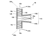
- 1A includes a point light source 2 and two optical paths that branch and guide light emitted from the point light source 2 in two different directions and have a T-shaped cross section.
- the illumination optical system 10A is provided. Therefore, the illumination optical system 10A includes an incident portion 1Aa that receives light emitted from the point light source 2, and a first optical path that branches and guides the light incident on the incident portion 1Aa in two different directions.
- the illumination optical system 10A includes a first reflecting portion 11A disposed close to the incident portion 1Aa, and a second reflecting portion 12A disposed opposite to the incident portion 1Aa.
- the first reflecting portion 11A and the first reflecting portion 11A Illumination light in which the first light reflected by the second reflecting portion 12A and the second light reflected by the second reflecting portion 12A without passing through the first reflecting portion 11A are combined. It injects from two injection parts.
- the first and second light beams are incident from the incident portion 1Aa, reflected at least once by the first reflecting portion 11A, and then reflected at least once by the second reflecting portion 12A.
- Illumination light can be configured with a luminous flux having a high efficiency, and a highly efficient illumination device having desired directivity characteristics and light distribution characteristics can be realized.
- the illuminating device that can efficiently illuminate only a necessary region even when the point light source 2 having a large divergence angle is used. Therefore, even if it is a compact structure, the illuminating device which has a desired light distribution characteristic and can perform highly efficient illumination can be obtained.
- a third reflecting portion 13A is provided opposite to the second reflecting portion 12A, and the third reflecting portion 13A receives light from the second reflecting portion 12A and reflects it again toward the second reflecting portion 12A, and then exits.
- the optical path length can be further increased, and the emitting part can be provided at a position where a desired part is illuminated. Therefore, it is possible to realize an illumination device that can efficiently illuminate a necessary area.
- the point light source 2 is, for example, an LED light source, and is a white LED light source that emits white light by combining a blue LED chip and a phosphor that is excited by light from the LED chip and emits excitation light of a predetermined wavelength.
- the illumination optical system 10A can be applied as an optical path of an illumination device that emits white light.
- the size of the white LED light source for example, a size of about 0.6 mm ⁇ 1.2 mm is widely used.
- the first light reflected by the second reflecting portion 12A without passing through the first reflecting portion 11A is indicated by a solid line in the drawing from the first emitting portion 1Ad.
- the second light emitted in the arrow DAa direction (optical path A) and reflected by the first reflecting portion 11A and the second reflecting portion 12A is emitted from the first emitting portion 1Ad in the arrow DBa direction indicated by the broken line in the drawing. (Optical path B).
- the optical path B includes the first reflecting portion 11A that functions only in the optical path B in addition to the optical path common to the optical path A. Therefore, by controlling the inclination and length of the first reflecting portion 11A, the directivity at the emitting portion is set. Characteristics and light distribution characteristics can be controlled independently of the optical path A.
- the light beam passing through the optical path A and the light beam passing through the optical path B are overlapped by controlling to emit in substantially the same direction as in the optical path A and the optical path B emitted from the first emitting unit 1Ad shown in the figure.
- the intensity of the illumination light can be increased and the desired direction can be efficiently illuminated.
- an illumination optical system capable of efficiently illuminating a desired direction can be configured.
- the illuminating device 1B of 2nd embodiment is demonstrated using FIG.
- This illuminating device 1B is also configured to include a point light source 2 and an illumination optical system 10B having a substantially T-shaped cross section, and an incident portion 1Ba that receives light emitted from the point light source 2 and the incident light.
- a first optical path 1Bb and a second optical path 1Bc for branching and guiding the light incident on the part 1Ba in two different directions; a first exit part 1Bd for emitting the branched and guided light;
- the first reflecting portion 11B is inclined so that the light path A and the light path B are emitted in different directions, and lighting having two different light distribution centers of gravity from one point light source is enabled. It is an example.
- the light distribution angle of the illumination light emitted from the emission unit can be controlled by inclining the first upper reflection surface 11Ba and the first lower reflection surface 11Bb. For example, it is possible to change the light distribution angle by inclining so that the distance between them becomes narrower as the distance from the light source increases.
- the first light reflected by the second reflecting portion 12B without passing through the first reflecting portion 11B is solid line in the figure from the first emitting portion 1Bd.
- the second light emitted in the direction of the arrow DAb indicated by (optical path Ab) and reflected by the first reflecting portion 11B and the second reflecting portion 12B is emitted from the first emitting portion 1Bd in the direction of the arrow DBb indicated by the broken line in the figure. (Optical path Bb).
- the illuminating device 1B which branches and guides the light inject
- the inclination of the first reflecting portion 11B that reflects the light emitted from the point light source 2 and the second reflecting portion 12B that is provided in a close position surrounding the point light source 2 arranged in the incident portion It is possible to control the light distribution characteristics by changing the inclination of the emitting portion which changes depending on the length of the third reflecting portion 13B and the length of the third reflecting portion 13B.
- the illumination device that guides the light emitted from the point light source 2 to two different exit surfaces via the optical path having a T-shaped cross section has been described above. It is also possible to form using Next, an illumination device having an illumination optical system provided with a light guide will be described.
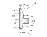
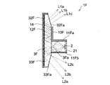
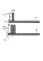
- FIG. 3 shows an illuminating device 1C according to a third embodiment using the light guide 3C.
- the light guide 3C has at least an incident surface on which light emitted from the point light source is incident, a second surface serving as a reflecting portion, and a third surface serving as an emitting portion.
- the light guide 3C is preferably applied to, for example, an illuminating device that is attached to the tip of a shelf and illuminates the top and bottom of the shelf at the same time, and splits the light emitted from one point light source 2 in two different directions. And guiding it. In this way, since the products displayed on the shelf are illuminated from two directions, upper and lower, it is difficult to produce a shadow, and the object surface can be illuminated uniformly.
- a light guide 3C includes an incident portion 31C, a first light guide portion 32C (corresponding to a first optical path), and a second light guide portion 33C (corresponding to a second optical path).
- the cross section is T-shaped, which is emitted in the direction, and is made of, for example, a translucent member (PMMA: acrylic) having a refractive index of about 1.5. Therefore, the total reflection angle is about 42 degrees.
- a first reflector 11C (a general term that combines the first upper reflector 11Ca and the first lower reflector 11Cb) is provided to hold the incident portion 31C corresponding to the T-shaped shaft section.
- the LED substrate 21 on which the LED light source constituting the shaped light source 2 is mounted is fixed.
- the light guide 3C, the first reflecting plate 11C, and the LED substrate 21 are long members whose longitudinal direction is the direction penetrating the drawing, and a plurality of point light sources 2 made of LED light sources are arranged in parallel in the longitudinal direction. The configuration is
- the incident portion 31C has a V-groove incident surface on the surface facing the point light source 2, and the first incident surface 31Ca and the second incident surface 31Cb that diverge the light beam in two different directions are in a V-groove shape.
- a light splitting portion is formed by providing a refractive surface having a substantially V-shaped cross section at a position facing the point light source 2 on the incident surface.
- the LED light source 2 is an LED light source
- the LED light source is disposed in a V-groove portion having a substantially V-shaped cross section formed on the incident surface. As described above, by arranging the LED light source in the V-groove portion, even if an LED light source having a large emission angle is used, it can be efficiently incident on the optical path, and a highly efficient illumination device can be realized. .
- the second reflecting plate 12C is attached to the surface (second surface) side facing the incident portion 31C
- the third reflecting plate 13C is attached to the back surface portion at a position facing the second reflecting plate 12C.
- the body part constituting the first light guide part 32C of the light guide 3C is sandwiched between the second reflector 12C and the third reflector 13C. That is, the second reflecting plate 12C and the third reflecting plate 13C are members that define the first optical path.
- the light guide 3C is composed of a transparent body having a refractive index of 1 or more as described above. In this embodiment, it is made of PMMA having a refractive index of about 1.5. However, a light guide made of a material other than this may be used, and a transparent resin such as a glass material or acrylic or polycarbonate other than PMMA may be used depending on the application. It may be used.
- the light guided through the light guide is totally reflected on the light guide surface when the total reflection condition is satisfied according to the refractive index of the light guide 3C.
- the light is reflected and does not satisfy the total reflection condition, it once exits the light guide 3C, is reflected by the reflecting plate surface, returns to the light guide again, and is guided to the exit surface.
- the intersection angle between the first incident surface 31Ca and the second incident surface 31Cb forming the light beam branching portion of the V-shaped cross section is, for example, 120 degrees. This crossing angle is set in the range of 90 to 150 degrees depending on the light emitting surface size and light emitting angle of the point light source 2, the thickness of the light guide 3C, the emission direction of the illumination light, and the like.
- the light emitted from the point light source 2 through this light beam branching portion is refracted from the straight traveling direction on the entrance surface having a V-shaped cross section, and in two different directions (for example, upward and downward) with respect to the straight traveling direction. The light is branched to the outgoing light and guided through the light guide toward the exit surface.
- the light beam L1 is emitted from the point light source 2, refracted by the first incident surface 31Ca, reaches the second surface without hitting the first upper reflection plate 11Ca, and is reflected by the second reflection plate 12C outside the second surface. After that, the light is repeatedly reflected from the third reflecting plate 13C, guided to the first exit surface 32Ca, refracted and emitted.
- the light beam L2 is emitted from the point light source 2, refracted by the second incident surface 31Cb, reaches the second surface without hitting the first lower reflecting plate 11Cb, and is reflected by the second reflecting plate 12C outside the second surface. After that, the light is guided to the second exit surface 33Ca, which is the lower exit surface, and is refracted and emitted.
- the light beam L3 is emitted from the point light source 2, refracted by the second incident surface 31Cb, totally reflected by the first lower reflecting plate 11Cb, and reaches the second surface. Thereafter, the light is guided to the first exit surface 32Ca by the behavior substantially the same as that of the light beam L1, and is refracted and emitted.
- the light beam L4 is emitted from the point light source 2, is refracted by the first incident surface 31Ca, is totally reflected by the first upper reflection plate 11Ca, and reaches the second surface. Thereafter, the light is guided to the second exit surface 33Ca by the behavior substantially the same as that of the light beam L3, and is refracted and emitted.
- the light emitted from the point light source 2 can be used efficiently as illumination light without waste, and is bright with high efficiency.
- An illumination device can be realized. The same applies to the behavior of the light rays L2 and L4.
- the light beams L1 and L3 and the light beams L2 and L4 are controlled to have similar light distribution characteristics. However, by controlling the light distribution characteristics in completely different directions, illumination is performed in a wider range. It is also possible to use a lighting device.
- the first emission surface 32Ca that is the upper emission surface is inclined at a predetermined angle, for example, about 20 degrees with respect to the second surface to which the second reflecting plate 12C is attached. Due to this inclination, most of the illumination light reaching the first exit surface 32Ca is refracted and emitted from the traveling direction further upward.
- the inclination angle of the first emission surface 32Ca is preferably inclined from the parallel position by a predetermined angle, for example, about 1 to 30 degrees, preferably 15 to 20 degrees.
- interval of a 2nd surface and a 3rd surface (injection surface) becomes narrow gradually as it leaves
- the third surface is emitted from the emission surface by giving the inclination of the third surface substantially parallel to the second surface and a thickness that decreases from the light source toward the tip of the emission surface. Illumination light can be emitted at an angle along the second surface, and a wide area can be efficiently illuminated even if the width of the illumination optical system is narrow.
- the second exit surface 33Ca which is the lower exit surface, is inclined at a predetermined angle, for example, 10 degrees, with respect to the second surface to which the second reflector 12C is attached. Due to this inclination, most of the illumination light that has reached the second exit surface 33Ca is emitted as illumination light having a light distribution center on the rear side of the upper illumination.
- the upper illumination is required to illuminate a wide range.
- the lower side illumination often illuminates the upper part of the object placed on the shelf below the shelf to which the illumination device is attached, and therefore often has a distance from the object to be illuminated. Therefore, by tilting the light distribution center of the lower illumination to the rear side, it becomes possible to illuminate the objects arranged to the back of the shelf board from the upper side. In other words, the object surface can be illuminated from the front and simultaneously from the top to the back, so that products placed on the shelf can be easily observed.
- the inner surface of the second reflecting plate 12C attached to the second surface is preferably a reflecting surface having a diffusing characteristic, and for example, a metal cover whose inner surface is painted white may be used.
- the degree of diffusion is desirably set to, for example, Gaussian scattering and a diffusion angle ⁇ of about 10 to 30 degrees. If the diffusion angle is too large, the illumination light diverges over a wide angle, which not only illuminates a useless area and lowers the illumination efficiency, but also moves toward the object observer (for example, product purchaser) and observes the object. In some cases, the illumination light may be unnecessary.
- the second surface of the light guide 3C to which the second reflector 12C is attached is also a diffusion surface.
- the surface can be diffused by providing fine irregularities on the surface of the light guide 3C.
- the degree of diffusion be the same as that of the diffusion surface provided on the inner surface of the second reflecting plate 12C.
- the diffusing portion 14 having a predetermined diffusion characteristic on the second surface side, the light diffused and reflected in a predetermined angle range is guided to the emission surface, and illumination light with reduced color unevenness and illuminance unevenness is emitted. It becomes possible to do.
- the second surface is provided with a diffusing portion 14 that reflects the incident light while diffusing the incident light in a predetermined angle range at a portion that reflects the reflected light toward the exit surface.
- a flat portion may be provided on the upper end surface 32Cb of the light guide 3C and covered with the extended surface of the second reflecting plate 12C. If it is such a structure, when this illuminating device 1C is used as an illuminating device for a shelf, even if illumination light is emitted upward from an illuminating device arranged below the observer's viewpoint, This is preferable because the observer is not dazzled and can be easily observed.
- a planar portion may be provided on the lower end surface 33Cb of the light guide 3C, and the illumination light may be emitted downward.
- the upper front surface of the object may not be illuminated with high quality only by illumination light emitted toward the rear. Therefore, as in the present embodiment, the lower stage can be illuminated with higher quality by emitting the illumination light in the direction directly below.
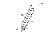
- the illumination device 1C is, for example, long as shown in FIG. 4, and has a configuration in which a plurality of point light sources 2 are arranged in parallel in the longitudinal direction. Further, the cross section is substantially T-shaped, and the length is, for example, about the width of the shelf board to be mounted.
- an LED substrate 21 having a length about the width of the shelf board is provided, and a plurality of LED light sources serving as the point light sources 2 are mounted thereon at a predetermined pitch.
- the shelf width may be configured to be divided into a plurality of substrates and electrically connected to each other.
- the LED light source installation interval may be set to a length of about the height of the second reflecting plate 12C (the height of the second surface of the light guide 3C).
- the light emitted from the adjacent light sources is mixed if the distance is shorter than the optical path length from the point light source 2 to the light emitted from the exit surface. If the interval between the point light sources 2 is widened, the number of the point light sources 2 to be installed can be reduced and the cost can be reduced.
- the length is shorter than the optical path length of the illumination light, for example, the height of the second reflector 12C as in this embodiment. It is preferable that the interval is.
- the cross section is T-shaped, the optical path length from the light source to the exit surface is longer than the width (thickness) of the illumination unit. Therefore, even if the size of the illumination unit is set to be thin in the vertical direction, the installation interval of the point light sources 2 can be set wide, which is advantageous for cost reduction.
- both sides of the illumination unit are covered with the side cover 15 so that illumination light is not emitted outward from the left and right end faces of the light guide 3C.
- the inner surface of the side cover 15 is a reflecting surface, and the illumination light that has reached the side cover 15 is returned again into the light guide 3C, reflected by one of the reflecting surfaces, and then emitted as illumination light from the exit surface.
- the illumination optical system 10C according to the present embodiment formed by the light guide 3C has a plurality of point light sources 2 arranged in parallel at a predetermined interval in the longitudinal direction of the T-section, and is long along the longitudinal direction. It has a small injection part. Therefore, it is possible to illuminate widely in the longitudinal direction of the illumination optical system with high illuminance using a plurality of point light sources 2. In addition, since it has an optical path that guides light while being repeatedly reflected, even if the arrangement pitch of a plurality of point light sources 2 arranged side by side is wide, it is possible to uniformly illuminate with reduced uneven illuminance in the longitudinal direction. Since the installation quantity of the shape light source may be small, the cost can be reduced.
- the illumination optical system described above is asymmetric in the vertical direction. Further, only the upper side has a back reflecting surface (third reflecting plate 13C), and a long optical path from the light source to the exit surface is secured.
- the light emitted from the illumination optical system can be efficiently guided to the illumination target by fixing the rear reflection surface to the shelf so that the rear surface of the rear reflection surface is in contact with the end surface of the shelf.
- the illuminating device 1C which includes the point light source 2 and the light guide 3C and is attached to the tip of the shelf, controls the light distribution of the point light source 2 to be bright and efficiently uniform in a desired specific direction. It is possible to illuminate, and it becomes possible to favorably illuminate a product displayed in a showcase having a plurality of shelf boards above and below.
- an LED light source with high luminance may be used for the LED light source that is the point light source 2, or more LED light sources may be installed.
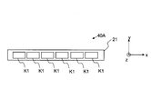
- 14A and 14B show a light source 40A that is an example of a light source 40 in which a plurality of LED light sources K1, which are white light sources, are densely arranged.
- 14A is a top view of the light source 40A
- FIG. 14B is a side view of the light source 40A.
- the LED light source K1 includes a phosphor 42 that converts blue light 43 into yellow light 44 with a predetermined conversion efficiency on a blue LED 41 having a light emission center 41a that emits blue light 43. A part of the blue light 43 is converted into yellow light 44 and the rest is emitted from the LED light source K1, so that the blue light 43 and the yellow light 44 are mixed to form white light.
- the phosphor 42 is formed so as to cover the entire upper part of the blue LED 41. Therefore, when the LED light sources K1 are arranged densely as shown in FIG. 14A, the phosphor 42 portions appear to be arranged continuously even though the light emission centers 41a of the blue LEDs 41 are arranged discretely. Since white light is emitted from the phosphor 42 portion, it looks as if it is a light source having a light emitting surface extending in the direction in which the LED light sources K1 are arranged (X direction in the figure).
- such a light source is a linear light source or a linearly long surface light source (XY plane). Therefore, in the present invention, it can be said that a light source having a light emitting surface extending in a direction perpendicular to the T-shaped cross section may be used instead of the row of the point light sources 2.
- the length in the direction (Y direction in the drawing) between the two reflecting surfaces forming the first reflecting portion 11A (see FIG. 1) is preferably as small as possible. In the case of a point light source, it goes without saying that the smaller the length in the direction between the two reflecting surfaces, the better.
- the point light source here refers to a light source in which, for example, the vertical and horizontal sizes of the light emitting surface for emitting light in the horizontal direction are sufficiently small compared to the size of the illumination optical system.
- it refers to a light source in which the length of a point light source in the direction is sufficiently small (for example, one third) with respect to the length in the direction between two reflecting surfaces forming the first reflecting portion 11A. With this size, the specific direction can be efficiently illuminated.
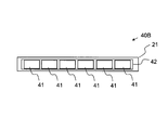
- FIGS. 15A and 15B there is a light source 40B shown in FIGS. 15A and 15B, for example.
- 15A is a top view of the light source 40B
- FIG. 15B is a side view of the light source 40B.
- the light source 40 ⁇ / b> B includes a substrate 21, a plurality of blue LEDs 41 mounted on the substrate 21, and a phosphor 42 that covers the plurality of blue LEDs 41.
- a wiring pattern for supplying power to the blue LED 41 is formed on the substrate 21, one electrode of the blue LED 41 is in contact with the wiring pattern, and the other electrode is wire bonded from the wiring pattern. Has been.
- Blue LED 41 is supplied with electric power and emits blue light 43 from the light emitting surface. As the blue light 43 travels through the phosphor 42, it is converted into yellow light 44 with a conversion efficiency in accordance with the characteristics of the phosphor 42. The light emitted from the phosphor 42 becomes white light by appropriately mixing the blue light 43 and the yellow light 44, and the light source 40B emits white light.
- FIG. 16 shows an example of an illuminating device 1C provided with such a light source 40 (40A, 40B) and a light guide 3C.
- a light source 40 40A, 40B
- a thin-line cold cathode tube 40A, 40B
- FIG. 17 shows a modification of the illuminating device 1C provided with such a light source 50 in FIG.
- the illuminating device 1C shown in FIG. 17 has a light source 50 made of a cold cathode tube mounted on a light guide 3C.
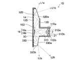
- FIG. 5 shows an illuminating device 1D according to a fourth embodiment in which the light splitting portion 16 having a V-shaped cross section is provided on the second surface of the light guide and the second reflecting plate. That is, this is an example in which the light guide 3D including the light beam branching portion 16 forms the illumination optical system 10D. Since the configuration other than the light beam branching portion 16 is the same as that of the lighting device 1C described above, it will not be described in detail.
- the light beam branching portion 16 has a substantially V-shaped cross section in which the first branch surface 16a and the second branch surface 16b intersect at a predetermined angle, and the light reflected by the first branch surface 16a is passed through the first light guide portion 32D.
- the light guided to the first exit surface 32Da and reflected by the second branch surface 16b is guided to the second exit surface 33Da via the second light guide 33D.
- a light guide 3D having a V-shaped concave portion on the second surface is used, and a second reflecting plate 12D having a V-shaped convex portion that matches the concave portion is used. It has a configuration that was.
- the light path length from when the light emitted from the light source substantially in the front direction reciprocates between the opposing second reflector and the light source member and is emitted from the emission section. Increases the temperature of the lighting device. Further, there is a high possibility that the light is emitted in an unnecessary direction, and the light use efficiency is also reduced.
- the light is emitted from the point light source 2, is incident from the second incident surface 31Db, is reflected by the first lower reflecting plate 11Db, reaches the second surface, and is reflected by the second reflecting plate 12D outside the second surface.
- the light beam L1a is repeatedly reflected from the third reflecting plate 13D, guided to the first exit surface 32Da, refracted and emitted from the point light source 2, and is incident from the first incident surface 31Da.
- the second surface as it is and reflected by the second reflecting plate 12D outside the second surface it is repeatedly reflected from the third reflecting plate 13D and guided to the first exit surface 32Da and refracted.
- the emitted light beam L1b After reaching the second surface as it is and reflected by the second reflecting plate 12D outside the second surface, it is repeatedly reflected from the third reflecting plate 13D and guided to the first exit surface 32Da and refracted.
- the emitted light beam L1b Further, light rays L2a and L2b whose light distribution is controlled in
- the reflecting surface other than the light beam branching portion 16 is a diffusing surface in the same manner as the lighting device 1C described above.
- a roughened diffusing portion 14 is provided in a portion close to the exit surface.
- the luminous flux branching portion 16 is used as a mirror surface, and all the light is favorably reflected and guided until reaching the diffusing portion 14, thereby enabling more efficient light distribution control of the illumination light. .
- FIG. 6 shows an illumination device 1E according to the fifth embodiment.
- This illuminating device 1E is an example in which both the upper side and the lower side of the bending point 17 facing the point light source 2 of the reflecting surface arranged facing the point light source 2 are inclined outward. It is the structure provided with the 2nd reflecting plate 12E which forms the light guide 3E in which the 2nd surface was bent, and the reflective surface which bent. Further, this bending point 17 becomes a light beam branching portion.
- this reflection surface that is, the second reflection plate 12F (second reflection portion) is an inclined surface that reflects incident light while diffusing it in a predetermined angle range.
- the light distribution control angle can be expanded by inclining the second reflecting portion, so that an illumination device capable of efficiently illuminating a necessary region can be realized.
- the first upper reflecting plate 11Ea and the first lower reflecting plate 11Eb in the vicinity of the light source, and the incident portion 31E of the light guide 3E are inclined so that the distance increases as the distance from the light source increases. Thereby, out of the light emitted from the light source, the light beam emitted in the normal direction with high emission intensity can be efficiently guided to the optical path branched in the vertical direction.
- the light is emitted from the point light source 2, is incident from the second incident surface 31Eb, is reflected by the first lower reflecting plate 11Eb, reaches the second surface, and is reflected by the second reflecting plate 12E outside the second surface. Thereafter, the light beam L1a is repeatedly reflected from the third reflecting plate 13E, guided to the first exit surface 32Ea, refracted upward, and emitted from the point light source 2, and the first entrance surface 31Ea. From the second reflection plate 12E outside the second surface, and then repeatedly reflected between the third reflection plate 13E and led to the first exit surface 32Ea, And a light beam L1b that is refracted and emitted downward. Further, light rays L2a and L2b whose light distribution is controlled in a predetermined direction are emitted from the lower side.
- the reflecting portion is provided with an inclined reflecting surface that is widened as the distance from the light source increases, the light reflected by the inclined reflecting surface is controlled in a direction in which the reflection angle decreases, From the upper and lower emission surfaces, the illumination light is controlled so as to irradiate more rearward in the horizontal direction. Thereby, each of upper side illumination and lower side illumination can illuminate a wider range.
- the above-described light guide 3 (3C, 3D, 3E) has been described as a T-shaped light guide having a cross section having an incident portion, a first light guide, and a second light guide.
- a plate-shaped light guide may be provided in the illumination optical system, and such a configuration example will be described with reference to FIGS.
- FIG. 7 shows a lighting device 1F of the sixth embodiment.
- This illuminating device 1F is an example in which a plate-shaped light guide 3F is disposed in a T-shaped illumination optical system, and a first surface on which light emitted from the point light source 2 is incident becomes an incident surface 3Fa.
- the upper side of the plate shape is the first light guide portion 32F and the lower side is the second light guide portion 33F.
- the light emitted from the point light source 2 located away from the incident surface 3Fa is reflected by the first lower reflecting plate 11Fb, and then reflected by the second reflecting plate 12F and the third reflecting plate 13F of the first light guide portion 32F.
- the light beams L2a and L2c that are reflected by the first upper reflection plate 11Fa and then reflected and emitted by the second reflection plate 12F of the first light guide portion 32F are directly emitted. It includes a light beam L2b that is emitted toward the second reflecting plate 12F, reflected by the second reflecting plate 12F, and emitted.
- the installation position of the point light source 2, the first vertical reflector, the second and third reflectors constituting the T-shaped illumination optical system, and Illumination light having desired light distribution characteristics can be realized by the inclination angle of the exit surface.
- the lighting device 1F described above uses the plate-shaped light guide 3F, the light guide has a simple light guide structure, and the cost can be reduced while controlling the light distribution of the illumination light.
- FIG. 8 shows a lighting device 1G of the seventh embodiment.
- This illuminating device 1G is an example in which a plate-shaped light guide 3G is disposed in a T-section illumination optical system.
- the light guide 3G is an example in which the first incident surface 31Ga and the second incident surface 31Gb which are light beam branching portions are provided on the incident surface of the sixth embodiment described above, and the light emitted from the point light source 2 Is efficiently branched into upper and lower light guides.
- the light guide 3G includes a first incident surface 31Ga intersecting a V-shaped cross section, an incident surface 3Ga formed with a second incident surface 31Gb, a plate-shaped first light guide portion 32G, and a second light guide portion. 33G. Then, the light is emitted from the point light source 2 from the upper first emission portion 32Ga, reflected by the first lower reflection plate 11Gb, and repeatedly reflected by the second reflection plate 12G and the third reflection plate 13G of the first light guide portion 32G.
- the light L1a emitted and the light L1b incident from the first incident surface 31Ga and repeatedly reflected by the second reflecting plate 12G and the third reflecting plate 13G to be emitted are controlled at a predetermined angle. Light is emitted.
- the light is emitted from the point light source 2, reflected by the first upper reflection plate 11Ga, and reflected and emitted by the second reflection plate 12G of the first light guide portion 32G.
- Illumination light whose light distribution is controlled at a predetermined angle, such as the light beam L2a and the light beam L2b incident from the second incident surface 31Gb and reflected by the second reflecting plate 12G, is emitted.
- the above-described diffusion portion 14 is provided on the reflection surface of the second reflecting plate 12G and the reflection surface of the light guide 3G, and the diffusion portion 14 diffuses and reflects within a predetermined angle range. It is possible to realize illumination light with improved color unevenness and illuminance unevenness by guiding the emitted light to the exit surface and refracting the exit surface at a predetermined angle.
- the lighting device 1G described above also uses the plate-shaped light guide 3G, it has a simple light guide structure and can realize an inexpensive and highly efficient lighting device.
- a light beam branching portion can be provided and can be branched in two different directions. Eighth and ninth embodiments provided with this light beam branching section will be described with reference to FIGS.
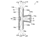
- the illuminating device 1H of the eighth embodiment shown in FIG. 9 has an illuminating optical system composed of only a reflecting surface without using a light guide. Further, a light beam branching portion 16 is formed on the second reflecting plate 12H.
- the light that has reached the first branch surface 16a is guided to the upper first light guide portion 1Hb, and the light that has reached the second branch surface 16b is the lower side. Is guided to the second light guide portion 1Hc.
- the light is emitted from the point light source 2 and reaches the first branch surface 16a as it is, is reflected toward the third reflecting plate 13H, and is emitted from the light source L1a emitted from the emission unit 1Hd or the point light source 2. Then, the light reaches the first branching surface 16a as it is, and is further reflected as it is toward the emitting portion 1Hd and is emitted by the light beam L1b, the first upper reflecting plate 11Ha, and the first lower reflecting plate 11Hb to be reflected to the second reflecting plate.
- the light beam L1c is emitted from the emitting portion 1Hd, and the light beam L1d is repeatedly reflected and emitted between the second reflecting plate 12H and the third reflecting plate 13H. Further, light rays L2a, L2b, L2c, L2d and the like whose light distribution is controlled so as to diffuse into a predetermined range are emitted from the lower emission portion 1He.
- the above-described diffusing portion 14 is provided on the reflecting surface of the second reflecting plate 12H, and light diffused and reflected by the diffusing portion 14 in a predetermined angle range from the emitting surface by a predetermined angle. By diffusing and emitting in the range, it is possible to realize illumination light with improved illuminance unevenness.
- the second reflecting portion (second reflecting plate 12H) is provided with a diffusing portion that reflects the incident light while diffusing the incident light in a predetermined angle range at a portion that reflects the reflected light toward the emitting portion.
- a diffusing portion that reflects the incident light while diffusing the incident light in a predetermined angle range at a portion that reflects the reflected light toward the emitting portion.
- the light distribution angle of the illumination light emitted from the emission part can be controlled by inclining the first upper reflector 11Ha and the first lower reflector 11Hb.
- the light distribution angle of the illumination light emitted from the emission unit can be controlled to be smaller than when arranged in parallel. it can.
- a light guide may be provided in the optical path of the illumination device 1H.
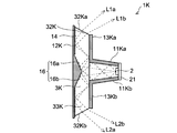
- the illumination device 1K according to the ninth embodiment is provided with a flat light guide 3K.
- first emission surface 32Ka, second emission surface 33Ka are inclined at a predetermined angle (for example, 50 degrees) with respect to the second reflecting plate 12K so that the emitted illumination light approaches the light source. Can be refracted.
- the exit surface (third surface) is inclined by 50 to 80 degrees from the parallel position with respect to the second surface (reflecting surface: second reflecting plate 12K), and the second surface and the third surface as the distance from the light source increases.
- the light is emitted from the point light source 2, reflected by the first upper reflecting plate 11Ka and the first lower reflecting plate 11Kb, reaches the first branch surface 16a, is reflected toward the third upper reflecting plate 13Ka, and further After returning to the second surface and being reflected by the second reflecting plate 12K outside the second surface, the light beam L1a emitted from the second emission surface 32Ka or the point light source 2 and emitted as it is to the first branch surface 16a. , And a light beam L1b that is repeatedly reflected and emitted between the third upper reflecting plate 13Ka and the second reflecting plate 12K. Further, light rays L2a, L2b and the like whose light distribution is controlled so as to be refracted at a predetermined angle and emitted from the lower second emission surface 33Ka are emitted.
- the light distribution angle of the emitted illumination light can be controlled by inclining the first upper reflector 11Ka and the first lower reflector 11Kb. For example, if the distance between each other is increased as the distance from the light source is increased, the light distribution angle of the illumination light emitted from the emission unit can be controlled to be larger than when arranged in parallel. it can.
- the lighting device 1K By mounting and using the lighting device 1K having the above-described configuration on a plate-like body, for example, the tip of a shelf board, it is possible to realize an illumination apparatus that effectively illuminates the vicinity of a desired portion of an object placed on the shelf board. .
- an illumination device effective for illuminating the tip end region of the shelf board can be realized.
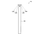
- the lighting device 1K can be used by being mounted on a plate-like body other than the shelf board.
- the both side regions of the partition wall can be effectively used. Can be illuminated. Therefore, an embodiment in which the lighting device 1K is mounted on the upper part of the partition wall will be described with reference to FIGS. 11A and 11B.
- the lighting device 1K is used by being mounted on the upper part of the partition wall 5A. Moreover, it is set as the structure which accommodates LED board 21 carrying the 1st upper reflecting plate 11Ka, the 1st lower reflecting plate 11Kb, and the point light source 2 in the accommodation recessed part 5Aa formed in the upper part of the partition wall 5A. That is, the projection of the lighting device 1K is fitted and held.
- the width of the lighting device 1K is approximately the same as the thickness of the partition wall 5A, and the illumination light is emitted obliquely downward from the inclined emission surfaces on both sides of the light guide 3K.
- light beams L3a and L3b whose light distribution is controlled in advance so as to be emitted toward the predetermined region are emitted on the left side of the partition wall 5A, and the predetermined region on the right side in advance.
- Light rays L4a and L4b whose light distribution is controlled so as to be emitted toward the light source are emitted.
- the emission direction of the illumination light can be defined in advance by the configuration of the illumination optical system, so that it is possible to realize a highly efficient illumination device by suppressing unnecessary light without emitting in an unnecessary direction.
- the point light sources 2 are arranged in a direction perpendicular to the paper surface at intervals wider than the thickness of the partition wall 5A. As described above, it is possible to effectively and efficiently illuminate the predetermined regions on both sides of the plate-like body (partition wall 5A) using the lighting device 1K according to the present embodiment.
- FIG. 12A shows a state in which the lighting device 1C is attached to the tip of the shelf board 5B, and illumination light whose light distribution is controlled at a predetermined angle is emitted to both the upper side and the lower side of the shelf board 5B.
- 1C of illuminating devices are attached to the front-end
- FIG. Further, the front of the product M1 placed on the shelf board 5B is supported by a guard body 8 having an upper guard rod 8a and a lower guard rod 8b fixed to the support member 7 to prevent the product M1 from falling. is doing.
- the light emitted from the point light source 2 is guided through the light guide 3C while being reflected by the second reflecting plate 12C and the third reflecting plate 13C of the light guide 3C, and is specified from the upper exit surface. It includes light rays L1a, L1b, and L1c whose light distribution is controlled in the direction. Further, light rays L2a, L2b, L2c, L2d and the like whose light distribution is controlled in a specific direction are emitted from the lower emission surface. At this time, it is good also as a structure which reflects a part of light (for example, light ray L2b) via the reflective surface 6a.
- the guard body 8 may be a plate-shaped guard plate made of a transparent resin plate. However, if the guard plate is used, the guard plate is disposed between the lighting device and the product, so that the illumination light is transmitted to the guard plate. The amount of light that is reflected on the surface of the product and illuminates the product is reduced. In addition, if the reflected light enters the eyes of the observer, it becomes dazzling and obstructs the observation of the product.
- the product M1 can be efficiently illuminated without the illumination light being blocked by the guard bar.
- the guard rod is preferably made of a material having a low reflectance and a large diffusion property. This is because if the reflectance of the guard rod is high, the illumination light is reflected and obstructs the observation of the product M1.
- the cross-sectional shape of the guard rod is preferably circular, and if it is circular, the illumination light diffused and reflected by the guard rod can be spread over a wider range and controlled so as not to hinder product observation.
- the shadow contrast of the guard rod projected on the product surface can be lowered, and higher-quality illumination can be realized. it can.
- the lower guard bar 8b is disposed in the vicinity of the tip of the shelf board 5B in order to regulate the position of the product M1, and the upper guard bar 8a is disposed in front of the lower guard bar 8b as long as the product M1 does not fall even if tilted. Thus, a certain interval can be secured from the product M1 whose position is regulated by the lower guard rod 8b.
- the illumination device according to the present embodiment that can illuminate two different directions can be suitably used for a showcase including a plurality of shelves.
- the lighting device 1C1 is mounted on the upper shelf plate 5C, and the lighting device 1C2 is mounted on the lower shelf plate 5D.
- the front surface of the product M1a placed on the shelf board 5C is illuminated by the light beam L11a emitted from the lighting device 1C1 attached to the upper shelf board 5C, and the light beam L21a emitted downward is used to illuminate the shelf board.
- the upper part of the product M2a placed on 5D is illuminated.
- the front of the product M2a placed on the shelf board 5D is illuminated by the light beam L12a emitted from the lighting device 1C2 mounted on the lower shelf board 5D, and the lower shelf is illuminated by the light beam L22a emitted downward. Illuminate the top of another product placed on the board.
- the upper and lower sides of the shelf can be illuminated at the same time using a single light source, so even a showcase displaying tall products on multiple shelf plates It is preferable because the upper part is effectively illuminated to facilitate observation.
- point light source 2 Although it was set as the embodiment using the chip-type LED light source as the point light source 2, other point light sources may be used, for example, a lens-mounted or bullet-type LED light source may be used.
- the incident light is incident from the incident part and reflected at least once by the first reflecting part.
- the illumination light can be constituted by a light beam having two types of optical paths, and a highly efficient illumination device having desired directivity characteristics and light distribution characteristics can be realized. For example, by superimposing the directivity characteristics of two light beams, it is possible to realize an illuminating device that can efficiently illuminate only a necessary region even when a point light source having a large divergence angle is used.
- the illumination device according to the present invention by using the illumination device according to the present invention, a compact illumination device that can efficiently illuminate a specific direction on both sides of the plate-like body can be realized. Therefore, even if it is a compact structure, the illuminating device which has a desired light distribution characteristic and can perform highly efficient illumination can be obtained.
- the illumination light can be controlled by refraction on each surface of the light guide, so that a higher performance and higher efficiency illumination device can be realized.
- the illuminating device according to the present invention can be suitably applied to an illuminating device for illuminating a tall product placed on a multistage showcase having a plurality of shelf boards on the upper and lower sides.
- 1A-1K Illumination device 2 Point light source (light source, LED light source) 3C to 3G Light guide 5A Partition wall 5B Shelf 10A to 10D Illumination optical system 11, 11A to 11H Incident surface 12 Reflecting surface 12Aa to 12Ha First reflecting surface 12Ab to 12Hb Second reflecting surface 13 Ejecting surface 14 Diffusing portion L1, L1a to L1d rays L2, L2a to L2d rays
Landscapes
- Engineering & Computer Science (AREA)
- General Engineering & Computer Science (AREA)
- Planar Illumination Modules (AREA)
- Freezers Or Refrigerated Showcases (AREA)
- Non-Portable Lighting Devices Or Systems Thereof (AREA)
Abstract
コンパクトな構成であっても、所望の配光特性を有し高効率な照明が可能な照明装置を得るために、光源(点状光源2)と、該光源から出射される光を入射する入射部と、該入射部に入射された光を異なる二方向に分岐して導光する第一、第二光学経路と、分岐され導光された光を射出する第一、第二射出部とを備えて断面がT型とされる照明光学系を有し、異なる二方向を同時に照明する照明装置1A~1Kであって、第一、第二射出部から、第一反射部および第二反射部で反射された第一の光と、第一反射部を介さずに第二反射部で反射された第二の光とが合成された照明光をそれぞれ射出する構成とした。
Description
本発明は、照明装置に関し、例えば、ショーケース等に配設され、ショーケースに陳列される商品の照明に好適な照明装置に関する。
従来から、ショーケースに配設され、ショーケースに陳列された商品を照明するものとして、蛍光灯が広く用いられている。蛍光灯は、一般に電気エネルギーを可視放射、赤外放射、紫外放射に変換し、可視光線を放射することで、照明として用いるものである。その際、熱損失が生じるため、蛍光灯自体のみならず、当該蛍光灯による輻射熱によって、陳列された商品が加熱されるという問題があり、ショーケース用の照明装置の光源としては、必ずしも好ましいものとはいえない。
近年、発光効率の向上や発光量の増加と共に、寿命が長く消費電力が小さくて、環境にやさしいとされるLED(Light Emitting Diode:発光ダイオード)を用いた照明装置が実用化されつつある。また、青色LEDチップが開発されて以来、この青色LEDチップと、このLEDチップからの光に励起されて所定波長の励起光を発光する蛍光体と、を組み合わせて白色発光する白色LED光源や、青色LEDチップと緑色LEDチップと赤色LEDチップとの三原色のLEDチップを用いて白色光を合成する白色LED光源が開発されている。
そのために、照明装置として、この白色LED光源を配設したLED照明装置が用いられている。特に、ショーケースなどの陳列棚の照明装置として、消費電力が小さく、発熱も小さいLED光源を用いることが模索されており、例えば、陳列室内を上方から照明するLED照明を設けたショーケースが既に提案されている(例えば、特許文献1参照)。
また、陳列棚の先端に設けられたプライスレール内にLED光源を配設して、光源の手前側に設けた反射板を介して棚の上下を照射するとしたショーケースが既に提案されている(例えば、特許文献2参照)。
ところで、特許文献1に記載されたショーケースのように、棚の上部から下部に向けて照明する方法では、棚板の水平面照度値は大きくなるが垂直面照度値は小さくなり、その結果、消費者が商品選択を行う際に手がかりとなる商品の正面が比較的暗くなってしまう。また、上方からの照明によって影が生じてしまい、見たい商品パッケージが見え難くなってしまう問題がある。
また、特許文献2に記載されたショーケースのように、一つのLED光源で棚の上下を同時に照明する構成では、少ない光源数で効率よく照明できるため、ある程度の照度を確保しながら光源の部品点数を抑えることができコスト削減図ることができる。しかし、棚の手前側に設置した反射板からの反射光により、商品の照明を行っているため、光源から射出された光の向きを変えて商品を照明しているのみであり、積極的に照明光の指向性制御や配光制御を行うことができない。
従って、牛乳パックや飲料ボトルなど背の高い商品を棚に陳列した際には、上側からの照明光も下側からの照明光も、綺麗な商標やロゴが印刷された商品中程当りに届き難くなり、消費者の視覚に訴えて購買意欲を喚起させる効果が小さくなる虞が生じる。
また、広範囲を照明するために反射板を大きくすると、照明装置ユニットが大きくなってしまったり、厚みが厚くなってしまったりして、意匠性が悪化して問題となる。
本発明は、上記の事情に鑑みてなされたものであって、コンパクトな構成であっても、所望の配光特性を有し高効率な照明が可能な照明装置を提供することを目的とする。
上記目的を達成するために本発明は、光源と、該光源から出射される光を入射する入射部と、該入射部に入射された光を異なる二方向に分岐して導光する第一、第二光学経路と、分岐され導光された光を射出する第一、第二射出部とを備えて断面がT型とされる照明光学系を有し、異なる二方向を同時に照明する照明装置であって、前記照明光学系は、前記入射部に近接配置された第一反射部と、当該入射部に対向して配置される第二反射部とを備え、前記第一、第二射出部から、前記第一反射部および前記第二反射部で反射された第一の光と、前記第一反射部を介さずに前記第二反射部で反射された第二の光とが合成された照明光をそれぞれ射出することを特徴としている。
上記の構成によると、断面がT型形状の照明光学系を用いることで、入射部より入射され第一反射部で少なくとも1度反射した後第二反射部で少なくとも一度反射され第一、第二射出部へ導かれる光束と、入射部より入射され第一反射部で反射することなく第二反射部で反射され第一、第二射出部へ導かれる光束と、の二種類の光路を有する光束で照明光を構成することができ、所望の指向特性、配光特性を有する高効率な照明装置を実現することが可能となる。例えば、二つの光束の指向特性を重ねることにより、発散角の大きな光源を用いても、必要な領域のみを効率的に照明可能な照明装置を実現することができる。そのために、コンパクトな構成であっても、所望の配光特性を有し高効率な照明が可能な照明装置を得ることができる。
また本発明は上記構成の照明装置において、前記照明光学系は、前記第二反射部に対向する第三反射部を備え、この第三反射部が前記第二反射部から光を受けて再び前記第二反射部に向けて反射し、それから、前記射出部から射出することを特徴としている。この構成によると、さらに光路長を長くすることができ、所望の部位を照明する位置に射出部を設けることが可能になる。そのために、必要な領域を効率的に照明可能な照明装置を実現することができる。
また本発明は上記構成の照明装置において、前記光源から出射される光を、前記第一、第二射出部に向かう光に分岐する光束分岐部を設けたことを特徴としている。この構成によると、光源から射出された照明光を、略反対方向に向かう光路を有する第一射出部と第二射出部への照明光に効率的に分岐することができる。
また本発明は上記構成の照明装置において、前記光束分岐部は、前記第二反射部の前記光源に対向する位置に配置され、略V型の凸反射面から構成されることを特徴としている。この構成によると、光源から射出され入射部から入射し、第一反射部または第三反射部で反射されることなく、直接第二反射部に到達する光を、V型の凸反射面で、第一射出部側および第二射出部側へ反射させることにより、特定方向を効率的に照明することができる。
また本発明は上記構成の照明装置において、前記照明光学系は、前記光源から出射される光が入射する入射面と、前記第二反射部に沿う第二面と、前記射出部となる第三面とを有する導光体を備えていることを特徴としている。この構成によると、光路中に導光体を配設することにより、導光体の各面における屈折により照明光を制御可能となるので、より高性能で高効率の照明装置を実現できる。
また本発明は上記構成の照明装置において、前記入射面の前記光源に対向する位置に、略V型断面の屈折面を設けて光束分岐部を形成したことを特徴としている。この構成によると、光源が射出する照明光を、直接受けて異なる二方向に分岐するので、それぞれの射出部に効率的に導光することができる。
また本発明は上記構成の照明装置において、前記第三面は、前記第二面に対して平行位置から1~30度傾斜しており、光源から離れるに従って第二面と第三面との間隔が徐々に狭くなっていることを特徴としている。この構成によると、第三面の傾きを第二面に略平行で、且つ、光源から射出面先端に向かうに従って厚みが減少するような傾きを持たせることにより、射出面から射出する照明光を第二面に沿った角度で射出することができ、照明光学系の幅が狭くても広範囲を効率的に照明することができる。
また本発明は上記構成の照明装置において、前記第三面は、前記第二面に対して平行位置から50~80度傾斜しており、光源から離れるに従って第二面と第三面との間隔が狭くなっていることを特徴としている。この構成によると、第三面の傾きを第二面の垂直方向に近い角度に設定することにより、射出面から射出する照明光を、第二面と垂直に近い方向を高効率に照明することができる。
また本発明は上記構成の照明装置において、前記第二反射部は、前記射出部に向けて反射光を反射する部位に、入射した光を所定角度範囲に拡散しながら反射する拡散部を設けていることを特徴としている。この構成によると、第二反射部により所定角度範囲に拡散された光が射出面から射出されるので、照度ムラや色ムラを改善した照明光を射出することができる。また、射出部に近接した部位に拡散部を設けているので、照明光を効率的に射出近傍まで導光することができる。
また本発明は上記構成の照明装置において、前記第二面は、前記射出面に向けて反射光を反射する部位に、入射した光を所定角度範囲に拡散しながら反射する拡散部を設けていることを特徴としている。この構成によると、反射面に拡散部を設けた導光体を備えた照明光学系を用いても、所定角度範囲に拡散された光が射出面から射出されるので、照度ムラや色ムラを改善した照明光を射出することができる。
また本発明は上記構成の照明装置において、前記第二反射部は、入射した光を所定角度範囲に拡散しながら反射する傾斜面とされることを特徴としている。この構成によると、第二反射部を傾斜させることにより、配光制御角度を拡大できるので、必要な領域を効率的に照明可能な照明装置を実現することができる。
また本発明は上記構成の照明装置において、前記照明光学系は、断面T型の長手方向に前記光源を所定間隔で複数並設し、この長手方向に沿って長寸の射出部を有することを特徴としている。この構成によると、複数の光源を用いて高照度で照明光学系の長手方向に広く照明が可能である。また、繰り返し反射しながら導光する光学経路を有するので、複数並設する光源の配置ピッチが広くても、長手方向の照度ムラを低減して一様に照明することができ、光源の設置数量が少なくてよいので、コストダウンが可能となる。
また本発明は上記構成の照明装置において、前記光源は点状光源であることを特徴としている。ここでいう点状光源とは、照明光学系の大きさと比較して、例えば光を水平方向に射出する発光面の上下左右のサイズが共に十分小さい光源をいう。かかる大きさにすることで、特定方向を効率的に照明することができる。
また本発明は上記構成の照明装置において、前記点状光源はLED光源からなることを特徴としている。この構成によると、高照度で、消費電力が小さく、発熱も小さいLED光源を用いて、高効率の照明装置を実現することができる。
また本発明は上記構成の照明装置において、前記LED光源は、前記入射面に形成した略V型断面のV溝部に配置されることを特徴としている。この構成によると、V溝部に配置することで、射出角度の大きなLED光源を用いても、光学経路中に効率的に入射することができ、高効率の照明装置を実現することができる。
また本発明は上記構成の照明装置において、前記光源は、前記T型の断面に垂直な方向に延在する発光面を備える光源であることを特徴としている。この構成によると、複数の点状光源を用いたい場合に、このように、T型の断面に垂直な方向に延在する発光面を備える光源を用いることで、一つの光源の採用で済むので、組付け調整が容易で、コストも安いというメリットを有する。
また本発明は上記構成の照明装置において、前記照明装置は板状体の先端部に装着され、当該板状体の両側をそれぞれ照明することを特徴としている。この構成によると、板状体の両側の特定方向を効率的に照明できるコンパクトな照明装置を実現することができる。
また本発明は上記構成の照明装置において、前記板状体は棚板であって、該棚板の上下を同時に照明することを特徴としている。この構成によると、ショーケースの棚板の先端に取り付けて、棚板の上下の商品側を広範囲に効率的に照明することができる。
本発明によれば、断面がT型形状の照明光学系を用いて、第一反射部および第二反射部で反射された第一の光と、第一反射部を介さずに第二反射部で反射された第二の光とが合成された照明光を、第一、第二射出部からそれぞれ射出する構成としたので、所望の指向特性、配光特性を有する高効率な照明が可能となる。そのためにコンパクトな構成であっても、所望の配光特性を有し高効率な照明が可能な照明装置を得ることができる。
以下に本発明の実施形態を図面を参照して説明する。また、同一構成部材については同一の符号を用い、詳細な説明は適宜省略する。
〈第一実施形態〉
まず、図1を用いて本発明に係る照明装置の第一実施形態例について説明する。なお、以下の説明においては、説明の簡素化のために、光源は点状光源であるとして説明するが、点状光源以外の光源、例えば、面状光源や線状光源を用いてもよい。図1に示す照明装置1Aは、点状光源2と、この点状光源2から出射される光を異なる二方向に分岐して導光する二つの光学経路を備えて断面がT型とされる照明光学系10Aを備えた構成とされる。そのため、この照明光学系10Aは、点状光源2から出射される光を入射する入射部1Aaと、該入射部1Aaに入射された光を異なる二方向に分岐して導光する第一光学経路1Ab、第二光学経路1Ac、と、分岐され導光された光を射出する第一射出部1Ad、第二射出部1Aeを備えている。
まず、図1を用いて本発明に係る照明装置の第一実施形態例について説明する。なお、以下の説明においては、説明の簡素化のために、光源は点状光源であるとして説明するが、点状光源以外の光源、例えば、面状光源や線状光源を用いてもよい。図1に示す照明装置1Aは、点状光源2と、この点状光源2から出射される光を異なる二方向に分岐して導光する二つの光学経路を備えて断面がT型とされる照明光学系10Aを備えた構成とされる。そのため、この照明光学系10Aは、点状光源2から出射される光を入射する入射部1Aaと、該入射部1Aaに入射された光を異なる二方向に分岐して導光する第一光学経路1Ab、第二光学経路1Ac、と、分岐され導光された光を射出する第一射出部1Ad、第二射出部1Aeを備えている。
また、この照明光学系10Aは、入射部1Aaに近接配置された第一反射部11Aと、該入射部1Aaに対向して配置される第二反射部12Aとを備え、第一反射部11Aおよび第二反射部12Aで反射された第一の光と、第一反射部11Aを介さずに第二反射部12Aで反射された第二の光とが合成された照明光を、第一、第二の射出部から、それぞれ射出する。
そのために、断面がT型形状の照明光学系10Aを用いることで、入射部1Aaより入射され第一反射部11Aで少なくとも一度反射した後第二反射部12Aで少なくとも一度反射され第一、第二射出部へ導かれる光束と、入射部1Aaより入射され第一反射部11Aで反射することなく第二反射部12Aで反射され第一、第二射出部へ導かれる光束と、の二種類の光路を有する光束で照明光を構成することができ、所望の指向特性、配光特性を有する高効率な照明装置を実現することが可能となる。例えば、二つの光束の指向特性を重ねることにより、発散角の大きな点状光源2を用いても、必要な領域のみを効率的に照明可能な照明装置を実現することができる。そのために、コンパクトな構成であっても、所望の配光特性を有し高効率な照明が可能な照明装置を得ることができる。
また、第二反射部12Aに対向する第三反射部13Aを備え、この第三反射部13Aが第二反射部12Aから光を受けて再び第二反射部12Aに向けて反射し、それから、射出部から射出することで、さらに光路長を長くすることができ、所望の部位を照明する位置に射出部を設けることが可能になる。そのために、必要な領域を効率的に照明可能な照明装置を実現することができる。
点状光源2は、例えばLED光源であって、青色LEDチップと、このLEDチップからの光に励起されて所定波長の励起光を発光する蛍光体と、を組み合わせて白色発光する白色LED光源を用いることで、この照明光学系10Aを白色発光する照明装置の光学経路として適用することができる。かかる白色LED光源の大きさとしては、例えば、0.6mm×1.2mm程度のものが汎用されている。
LED光源からなる点状光源2が射出する光のうち、第一反射部11Aを介さずに第二反射部12Aで反射された第一の光は第一射出部1Adから図中の実線で示す矢印DAa方向に射出され(光路A)、第一反射部11Aおよび第二反射部12Aで反射された第二の光は第一射出部1Adから図中の破線に示す矢印DBa方向に射出される(光路B)。
光路Bは、光路Aと共通の光路の他に、光路Bのみに機能する第一反射部11Aを含むので、第一反射部11Aの傾きや長さを制御することで、射出部での指向性や配光特性を光路Aと独立に制御することができる。
例えば、図中に示す第一射出部1Adから射出する光路Aと光路Bのように、ほぼ同じ方向に射出するように制御して、光路Aを通る光束と光路Bを通る光束とを重ね合わせることで、照明光の強度を高くして、所望の方向を効率的に照明可能となる。
そのために、発散角の大きな点状光源を用いた場合でも、所望の方向を効率的に照明可能な照明光学系を構成することができる。
〈第二実施形態〉
次に、図2を用いて第二実施形態の照明装置1Bについて説明する。この照明装置1Bも、点状光源2と、断面がほぼT型とされる照明光学系10Bを備えた構成とされ、点状光源2から出射される光を入射する入射部1Baと、該入射部1Baに入射された光を異なる二方向に分岐して導光する第一光学経路1Bb、第二光学経路1Bc、と、分岐され導光された光を射出する第一射出部1Bd、第二射出部1Beとを備えて,異なる二方向を同時に照明する照明装置である。
次に、図2を用いて第二実施形態の照明装置1Bについて説明する。この照明装置1Bも、点状光源2と、断面がほぼT型とされる照明光学系10Bを備えた構成とされ、点状光源2から出射される光を入射する入射部1Baと、該入射部1Baに入射された光を異なる二方向に分岐して導光する第一光学経路1Bb、第二光学経路1Bc、と、分岐され導光された光を射出する第一射出部1Bd、第二射出部1Beとを備えて,異なる二方向を同時に照明する照明装置である。
ただし、第一反射部11Bを傾斜させて、光路Aと光路Bが異なる方向に射出するように構成した点が異なり、一つの点状光源から異なる二つの配光重心を有する照明を可能にした例である。例えば、第一上反射面11Baと第一下反射面11Bbを傾斜させることで、射出部から射出される照明光の配光角度を制御できる。例えば、互いの間隔が光源から遠ざかるに従って狭くなるように傾斜させることで、配光角度を変えることができる。
すなわち、LED光源からなる点状光源2が射出する光のうち、第一反射部11Bを介さずに第二反射部12Bで反射された第一の光は第一射出部1Bdから図中の実線で示す矢印DAb方向に射出され(光路Ab)、第一反射部11Bおよび第二反射部12Bで反射された第二の光は第一射出部1Bdから図中の破線に示す矢印DBb方向に射出される(光路Bb)。
上記の構成であれば、入射部1Baに設置する点状光源2から射出された光を図の上下に分岐して導光し、それぞれ広範囲に照射する照明装置1Bとなる。
このように、入射部に配置される点状光源2を囲む近接した位置に設けられ、点状光源2から射出された光を反射する第一反射部11Bの傾斜、および、第二反射部12Bの長さと第三反射部13Bの長さにより変化する射出部の傾きなどを変化させて、配光特性を制御することが可能である。
以上、断面T型の光学経路を介して、点状光源2が射出する光を異なる二つの射出面に導光する照明装置について説明したが、この光学経路を、透光性を有する導光体を用いて形成することも可能である。次に、導光体を備えた照明光学系を有する照明装置について説明する。
〈第三実施形態〉
図3に導光体3Cを用いた第三実施形態の照明装置1Cを示す。
図3に導光体3Cを用いた第三実施形態の照明装置1Cを示す。
導光体3Cは、点状光源から出射される光が入射する入射面と、反射部となる第二面と、射出部となる第三面とを少なくとも有する。また、この導光体3Cは、例えば、棚板の先端に取り付けて、棚の上下を同時に照明する照明装置に好適に適用され、一つの点状光源2が射出する光を異なる二方向に分岐して導光している。このように、棚に陳列した商品を上下の二方向から照明するので、影ができ難く、物体表面を均一に照明可能である。
本実施形態に係る導光体3Cは、入射部31Cと第一導光部32C(第一光学経路に相当)と第二導光部33C(第二光学経路に相当)とを備えて異なる二方向に射出する断面T型とされ、例えば、屈折率が約1.5の透光性部材(PMMA:アクリル)製からなる。そのために、全反射角は約42度となる。
断面T型の軸部に相当する入射部31Cを保持する第一反射板11C(第一上反射板11Caと第一下反射板11Cbを合わせた総称)を設け、この第一反射板11Cに点状光源2を構成するLED光源を搭載するLED基板21を固定する。導光体3C、第一反射板11C、および、LED基板21は、図面を貫通する方向を長手方向とする長尺部材とされ、LED光源からなる点状光源2が長手方向に複数並設された構成とされる。
入射部31Cは、点状光源2に対向する面にV溝状の入射面を備えており、異なる二方向に光束を分岐する第一入射面31Caと第二入射面31CbとがV溝状に交差している。すなわち、入射面の点状光源2に対向する位置に、略V型断面の屈折面を設けて光束分岐部を形成している。このような構成であれば、点状光源2が射出する光を、直接受けて異なる二方向に分岐するので、それぞれの射出部(第一射出面32Ca、第二射出面33Ca)に効率的に導光することができて好ましい。
点状光源2がLED光源であれば、このLED光源は、入射面に形成した略V型断面のV溝部に配置されることになる。このように、LED光源をV溝部に配置することで、射出角度の大きなLED光源を用いても、光学経路中に効率的に入射することができ、高効率の照明装置を実現することができる。
また、入射部31Cに対向する面(第二面)側に第二反射板12Cを取り付け、この第二反射板12Cと対向する位置にある背面部に第三反射板13Cを取り付けていて、この第二反射板12Cと第三反射板13Cとで、導光体3Cの第一導光部32Cを構成する胴体部を挟持する。すなわち、第二反射板12Cと第三反射板13Cは、第一光学経路を規定する部材となる。
導光体3Cは前述したように屈折率1以上の透明体で構成される。本実施形態では、屈折率が約1.5のPMMA製としたが、これ以外の材質からなる導光体でもよく、用途に応じて、ガラス材料、PMMA以外のアクリルやポリカなどの透明樹脂を用いてもよい。
導光体3Cと全ての反射板の間は空気層であり、導光体中を導光する光は、導光体3Cの屈折率に応じ、全反射条件を満足する場合は、導光体面で全反射し、全反射条件を満足しない場合は、一旦導光体3Cから出た後、反射板面で反射し、再び導光体中に戻り、射出面に至るまで導光される。
V型断面の光束分岐部を形成する第一入射面31Caと第二入射面31Cbの交差角度は例えば120度である。この交差角度は、点状光源2の発光面サイズや発光角、導光体3Cの厚み、照明光の射出方向などにより、90~150度の範囲で設定される。この光束分岐部を介して、点状光源2から射出された光は、断面V型の入射面で、直進方向から屈折され、直進方向に対し、異なる二方向に(例えば、上側と下側に向かう光に)分岐され、導光体中を射出面に向かって導光される。
また、図中に、照明光の主な光線を破線で示す。光線L1は、点状光源2から射出し、第一入射面31Caで屈折し、第一上反射板11Caに当らず第二面に到達し、第二面外側の第二反射板12Cで反射された後、第三反射板13Cとの間で繰り返し反射して第一射出面32Caに導かれ、屈折して射出される。
光線L2は、点状光源2から射出し、第二入射面31Cbで屈折し、第一下反射板11Cbに当らず第二面に到達し、第二面外側の第二反射板12Cで反射された後、下側射出面となる第二射出面33Caに導かれ、屈折して射出される。
光線L3は、点状光源2から射出し、第二入射面31Cbで屈折し、第一下反射板11Cbで全反射して第二面に到達する。その後、光線L1と略同様の振る舞いにより第一射出面32Caに導かれ、屈折して射出される。
光線L4は、点状光源2から射出し、第一入射面31Caで屈折し、第一上反射板11Caで全反射して第二面に到達する。その後、光線L3と略同様の振る舞いにより第二射出面33Caに導かれ、屈折して射出される。
そのために、第一上反射板11Caと第一下反射板11Cbの間隔および長さを最適に設定することにより、光線L1と同様の振る舞いをする光束と、光線L3と同様の振る舞いをする光束の配光特性が、共に所望の照明光配光特性となるように制御することにより、点状光源2から射出された光を無駄なく、効率的に照明光として用いることができ、高効率の明るい照明装置を実現することができる。光線L2と光線L4の振る舞いについても同様である。
本実施形態では、光線L1とL3、光線L2とL4が、同様の配光特性を有するように制御したが、全く異なる方向の配光特性を持つように制御することにより、より広範囲に照明する照明装置とすることも可能である。
また、例えば、上側射出面である第一射出面32Caは、第二反射板12Cを取り付ける第二面に対して所定角度、例えば約20度傾いている。この傾きにより、第一射出面32Caに到達した照明光の多くは進行方向から、より上方に向かって屈折され射出される。
上記したように、この第一射出面32Caの傾斜角度は、第二面に対して平行位置から所定角度、例えば1~30度程度、好ましくは15~20度傾斜していることが好ましい。また、光源から離れるに従って第二面と第三面(射出面)との間隔が徐々に狭くなっていることが好ましい。このような構成であれば、第三面の傾きを第二面に略平行で、且つ、光源から射出面先端に向かうに従って厚みが減少するような傾きを持たせることにより、射出面から射出する照明光を第二面に沿った角度で射出することができ、照明光学系の幅が狭くても広範囲を効率的に照明することができる。
また、下側射出面である第二射出面33Caは、第二反射板12Cを取り付ける第二面に対して所定角度、例えば10度傾いている。この傾きにより、第二射出面33Caに到達した照明光の多くは、上方照明よりも、より後ろ側に配光中心を有する照明光として射出される。
上側照明は、射出面近くに被照明物体の面が配置されることが多いため、広範囲に照明することが求められる。一方、下側照明は、照明装置が取り付けられる棚板の一段下の棚板に載置された物体の上部を照明するため、被照明物体と距離があることが多い。そのために、下側照明の配光中心を後ろ側に傾けることにより、棚板の奥まで並べられた物体を上側から照明することが可能となる。すなわち、物体表面を正面から照明すると同時に、上方から奥の方まで照明でき、棚に載置された商品などを容易に観察できる。
また、第二面に取り付ける第二反射板12Cの内面は、拡散特性を有する反射面であることが好ましく、例えば、金属製カバーの内面を白塗装したものを用いるとよい。この拡散度合いは、例えばガウス散乱、拡散角度σが10~30度程度に設定されることが望ましい。拡散角度が大きすぎると、照明光が広角度に発散してしまい、無駄な領域まで照明し照明効率が下がるだけでなく、物体の観察者(例えば、商品の購入者)側へ向かい、物体観察を邪魔するような不要な照明光となる場合もある。
第二反射板12Cを取り付ける導光体3Cの第二面も拡散面であることが好ましい。例えば、導光体3Cの表面に細かな凹凸を設けることにより拡散面化することができる。また、この拡散度合いも、上記した第二反射板12Cの内面に設ける拡散面と同程度の拡散特性であることが望ましい。
上側射出面および下側射出面からの照明光は、その多くが射出面で屈折する。従って、導光体材料の色分散度合いにより、照明光に色ムラが生じることがある。また、一度射出面に当っても全反射して第二面側に異なる角度で向かい、再度第二面および第二反射板12Cで反射されて射出面から射出する光束も存在する。射出面での全反射回数の違いにより、射出面からの射出方向が異なるため、照度ムラが生じる。この際に、第二反射板12C内面と導光体3の第二面を拡散面化することにより、これらの色ムラや照度ムラを改善し、より均一な高品位な照明装置を実現することができる。
すなわち、第二面側に所定の拡散特性を有する拡散部14を設けることで、所定の角度範囲に拡散され反射された光を射出面に導き、色ムラや照度ムラを低減した照明光を射出することが可能となる。このように、第二面は、射出面に向けて反射光を反射する部位に、入射した光を所定角度範囲に拡散しながら反射する拡散部14を設けていることが好ましい。このような構成であれば、反射面に拡散部を設けた導光体を備えた照明光学系を用いても、所定角度範囲に拡散された光が射出面から射出されるので、照度ムラや色ムラを改善した照明光を射出することができる。
また、導光体3Cの上端面32Cbに平面部が設けられ、第二反射板12Cの延長面で覆われていてもよい。このような構成であれば、この照明装置1Cを棚板の照明装置として用いたとき、観察者の視点よりも下方に配置される照明装置から、照明光が上側に向かって射出されても、観察者がまぶしくならず、容易に観察することができて好ましい。
また、導光体3Cの下端面33Cbに平面部が設けられ、照明光を下側にも射出する構成とされていてもよい。例えば、棚板の先端位置が下段に従って手前に配置される棚の場合には、後方に向けて射出される照明光のみでは、物体の上前面を高品位に照明することができないことがある。そのために、本実施形態のように、下方の直下方向にも照明光を射出することにより、下段をより高品位に照明することができる。
照明装置1Cは、例えば、図4に示すように、長尺とされ、長手方向に複数の点状光源2を並設した構成とされる。また、その断面は略T型であって、その長さは、例えば、装着する棚板の幅程度の長さである。
そのために、棚板の全幅を均一に照明するために、棚板の幅程度の長さのLED基板21を設け、この上に点状光源2となるLED光源を所定ピッチで複数個搭載している。ただし、棚幅が広い場合は、複数の基板に分け、それぞれを電気的に接続する構成としてもよい。また、このLED光源の設置間隔は、第二反射板12Cの高さ(導光体3Cの第二面の高さ)程度の長さに設定されておればよい。
これは、点状光源2から発光して射出面から射出されるまでの光路長よりも短い間隔であれば、隣り合う光源同士の射出光が混ざり合うからである。点状光源2の間隔を広く取ると、点状光源2の設置数量を減らすことができコストダウンできる。
しかし、設置間隔が広くなればなるほど、長手方向の照度ムラができ易くなるため、照明光の光路長よりも短い長さ、例えば、本実施形態のように、第二反射板12Cの高さ程度の間隔であることが好ましい。
また、本実施形態では、断面T型としているため、光源から射出面に至る光路長は、照明ユニットの幅(厚さ)よりも長くなる。従って、照明ユニットのサイズを上下方向に薄型に設定しても、点状光源2の設置間隔を広く設定することが可能となり、コストダウン化に有利な構成である。
照明ユニットの両サイドは、サイドカバー15で覆われ、導光体3Cの左右両端面から外側に照明光が射出されないことが好ましい。また、サイドカバー15の内面は反射面とされ、サイドカバー15に到達した照明光は再度導光体3C内に戻され、いずれかの反射面で反射した後、射出面から照明光として射出される。
このように、導光体3Cにより形成される本実施形態に係る照明光学系10Cは、断面T型の長手方向に点状光源2を所定間隔で複数並設し、この長手方向に沿って長寸の射出部を有する。そのために、複数の点状光源2を用いて高照度で照明光学系の長手方向に広く照明が可能である。また、繰り返し反射しながら導光する光学経路を有するので、複数並設する点状光源2の配置ピッチが広くても、長手方向の照度ムラを低減して一様に照明することができ、点状光源の設置数量が少なくてよいので、コストダウンが可能となる。
上記した照明光学系は、上下方向に非対称である。また、上側のみに背面反射面(第三反射板13C)を有し、光源から射出面までの光路を長く確保している。この背面反射面の後方が、棚板の端面に接するように棚板に固定することにより、照明光学系から射出する光を、効率的に照明対象物に導くことができる。
そのために、点状光源2と導光体3Cを備え、棚板の先端に装着される照明装置1Cは、点状光源2の光を配光制御して所望の特定方向に明るく効率よく均一に照明することができて、上下に複数段の棚板を有するショーケースに陳列された商品を良好に照明することが可能となる。
なお、この照明装置1Cを、より高い照度にするには、点状光源2であるLED光源に高い輝度のLED光源を用いるか、または、より多くのLED光源を設置すればよい。図14A、14Bに白色光源であるLED光源K1を密に複数個並べてなる光源40の一例である光源40Aを示す。図14Aは光源40Aの上面図であり、図14Bは光源40Aの側面図である。
LED光源K1は、青色光43を発する発光中心41aを備える青色LED41上に、青色光43を所定の変換効率で黄色光44に変換する蛍光体42を有してなる。青色光43は一部が黄色光44に変換され、残りはLED光源K1を出射するので、青色光43と黄色光44とが混じり合うことで白色光が形成される。
蛍光体42は、青色LED41の上部全体を覆うように形成される。そのため、LED光源K1を図14Aのように密に配置すると、青色LED41の発光中心41aは離散的に配置されていても、蛍光体42部分は連続して配置されているように見える。蛍光体42部分から白色光が出射されるので、LED光源K1を配列する方向(図ではX方向)に延在する発光面を備える光源であるかのように見えることとなる。
かかる光源は線状光源であるということもできるし、線状に長い面光源(XY面)であるとも言える。このことから、本発明においては、点状光源2の列に替えて、T字型の断面に垂直な方向に延在する発光面を備える光源を用いてもよいと言える。かかる光源における第一反射部11A(図1参照)をなす二つの反射面の間の方向(図ではY方向)の長さは小さいほど好ましい。なお、点状光源の場合も、二つの反射面の間の方向の長さは小さいほど好ましいことは言うまでもない。
すなわち、ここでいう点状光源とは、照明光学系の大きさと比較して、例えば光を水平方向に射出する発光面の上下左右のサイズが共に十分小さい光源をいう。例えば、第一反射部11Aをなす二つの反射面の間の方向の長さに対して、点状光源のその方向の長さが十分小さい(例えば3分の1)光源を言う。かかる大きさにすることで、特定方向を効率的に照明することができる。
点状光源であるLEDを配列する方向に延在する発光面を備える光源の他の例としては、例えば図15A、15Bに示す光源40Bがある。図15Aは光源40Bの上面図、図15Bは光源40Bの側面図である。この光源40Bは、基板21と、基板21の上に実装された複数の青色LED41と、複数の青色LED41を覆う蛍光体42とを備えている。基板21上には、青色LED41に電力を供給するための配線パターンが形成されており、青色LED41の一方の電極はその配線パターン上に接触しており、他方の電極へは配線パターンからワイヤボンディングされている。
青色LED41は電力の供給を受けて、発光面から青色光43を発光する。青色光43は、蛍光体42内を進行するにあたり、その蛍光体42の特性に応じた変換効率で黄色光44に変換される。蛍光体42を出射する光は青色光43と黄色光44とが適度に混じることで白色光になり、光源40Bは白色光を出射することとなる。
図16は、かかる光源40(40A、40B)と導光体3Cを備えた照明装置1Cの一例を示す。また、かかる光源40に相当する他の例としては細線状の冷陰極管がある。かかる光源50を備えた照明装置1Cの変形例を図17に示す。図17に示す照明装置1Cは、導光体3Cに冷陰極管からなる光源50が実装されてなる。
次に、点状光源2が射出する光を確実に分岐させる光束分岐部を備えた照明装置について、図5および図6を用いて説明する。
〈第四実施形態〉
図5には、導光体の第二面および第二反射板にV型断面を有する光束分岐部16を備えた第四実施形態の照明装置1Dを示している。すなわち、光束分岐部16を備えた導光体3Dが照明光学系10Dを形成している例である。この光束分岐部16以外の構成は、前述した照明装置1Cと同様であるので詳述しない。
図5には、導光体の第二面および第二反射板にV型断面を有する光束分岐部16を備えた第四実施形態の照明装置1Dを示している。すなわち、光束分岐部16を備えた導光体3Dが照明光学系10Dを形成している例である。この光束分岐部16以外の構成は、前述した照明装置1Cと同様であるので詳述しない。
光束分岐部16は、第一分岐面16aと第二分岐面16bとが所定角度で交差した略V型断面とされ、第一分岐面16aで反射した光を第一導光部32Dを介して第一射出面32Daに導き、第二分岐面16bで反射した光を第二導光部33Dを介して第二射出面33Daに導く。
また、この光束分岐部16を設けるために、第二面にV形状の凹部を備えた導光体3Dとし、この凹部に合致する断面V型の凸部を備えた第二反射板12Dを用いた構成としている。このような光束分岐部16を備えていない状態では、光源から略正面方向に射出された光は、対向する第二反射板と光源部材間を往復し、射出部から射出されるまでの光路長が長くなるため、照明装置の温度上昇の原因となる。また、不要な方向に射出する可能性が高くなり、光利用効率も低下してしまう。
このように、光束分岐部16を追加することにより、上側および下側の射出面から射出する照明光の配光重心をさらに上方または下方に向けることが可能になり、より広範囲を効率的に照明することができる。そのために、背の高い商品を陳列するために間隔が広くなった棚板でも、商品を視認し易い方向に照明光を射出して、均一に照明することが可能となる。
例えば、点状光源2から射出し、第二入射面31Dbから入射し、第一下反射板11Dbで反射して第二面に到達し、第二面外側の第二反射板12Dで反射された後、第三反射板13Dとの間で繰り返し反射して第一射出面32Daに導かれ、屈折して射出される光線L1aと、点状光源2から射出し、第一入射面31Daから入射し、そのまま第二面に到達し、第二面外側の第二反射板12Dで反射された後、第三反射板13Dとの間で繰り返し反射して第一射出面32Daに導かれ、屈折して射出される光線L1bとを有する。また、下側からも所定方向に配光制御された光線L2a、L2bが射出される。
また、この光束分岐部16以外の反射面は前述した照明装置1Cと同様に拡散面化されていることが好ましい。例えば、射出面に近接した部位に粗面化された拡散部14を設ける構成とする。さらに、この光束分岐部16を鏡面として、拡散部14に至るまでは全ての光を良好に反射して導光することで、より効率的に照明光の配光制御を行うことが可能となる。
〈第五実施形態〉
図6に第五実施形態の照明装置1Eを示す。この照明装置1Eは、点状光源2に対向して配置される反射面の、点状光源2に対向する屈曲点17の上側と下側を共に外側に向けて傾斜させた例であって、第二面が屈曲した導光体3Eと屈曲した反射面を形成する第二反射板12Eを備えた構成である。また、この屈曲点17が光束分岐部となる。
図6に第五実施形態の照明装置1Eを示す。この照明装置1Eは、点状光源2に対向して配置される反射面の、点状光源2に対向する屈曲点17の上側と下側を共に外側に向けて傾斜させた例であって、第二面が屈曲した導光体3Eと屈曲した反射面を形成する第二反射板12Eを備えた構成である。また、この屈曲点17が光束分岐部となる。
このように、反射面全体を射出部まで傾けることにより、導光される光の進行方向が、反射を繰り返す毎に徐々に広がって行き、最終的に射出される照明光の上下方向の広がり角を大きく確保することができる。
そのために、この反射面すなわち第二反射板12F(第二反射部)は、入射した光を所定角度範囲に拡散しながら反射する傾斜面とされる。このような構成であれば、第二反射部を傾斜させることにより、配光制御角度を拡大できるので、必要な領域を効率的に照明可能な照明装置を実現することができて好ましい。
また、光源近傍の第一上反射板11Eaと第一下反射板11Eb、および、導光体3Eの入射部31Eは、光源から離れるに従って間隔が広がるように傾斜している。これにより、光源から射出される光のうち、発光強度の高い法線方向に射出される光束を効率的に上下方向に分岐される光路に導くことができる。
例えば、点状光源2から射出し、第二入射面31Ebから入射し、第一下反射板11Ebで反射して第二面に到達し、第二面外側の第二反射板12Eで反射された後、第三反射板13Eとの間で繰り返し反射して第一射出面32Eaに導かれ、より上向きに屈折して射出される光線L1aと、点状光源2から射出し、第一入射面31Eaから入射し、そのまま第二面に到達し、第二面外側の第二反射板12Eで反射された後、第三反射板13Eとの間で繰り返し反射して第一射出面32Eaに導かれ、より下向きに屈折して射出される光線L1bとを有する。また、下側からも所定方向に配光制御された光線L2a、L2bが射出される。
このように、入射部に光源から離れるに従って間隔が広がるように傾斜した反射面を設けた構成であれば、この傾斜した反射面で反射した光は、その反射角度が小さくなる方向に制御され、上下の射出面から、それぞれ水平方向に近い、より後方を照射する照明光に制御される。これにより、上側照明、下側照明のそれぞれが、より広い範囲を照明することが可能となる。
上記した導光体3(3C、3D、3E)は、いずれも、入射部と第一導光部と第二導光部とを備える断面T型の導光体として説明したが、断面T型の照明光学系に板状の導光体を配設してもよく、このような構成例について図7、図8を用いて説明する。
〈第六実施形態〉
図7に第六実施形態の照明装置1Fを示す。この照明装置1Fは、断面T型の照明光学系に板状の導光体3Fを配設した例であって、点状光源2が射出する光が入射する第一面が入射面3Faとなる。また、板状の上側が第一導光部32Fとなり下側が第二導光部33Fとなる。
図7に第六実施形態の照明装置1Fを示す。この照明装置1Fは、断面T型の照明光学系に板状の導光体3Fを配設した例であって、点状光源2が射出する光が入射する第一面が入射面3Faとなる。また、板状の上側が第一導光部32Fとなり下側が第二導光部33Fとなる。
入射面3Faから離れた位置にある点状光源2から射出された光は、第一下反射板11Fbで反射した後、第一導光部32Fの第二反射板12Fと第三反射板13Fで繰り返し反射して第一射出部32Faから射出される光線L1a、L1bや、直接第二反射板12Fに向けて射出され、その後第三反射板13Fとの間で繰り返し反射して第一射出部32Faから射出される光線L1cを含む。また、下側の第二射出部33Faからは、第一上反射板11Faで反射した後、第一導光部32Fの第二反射板12Fで反射して射出される光線L2a、L2cや、直接第二反射板12Fに向けて射出され、この第二反射板12Fで反射して射出される光線L2bを含む。
上記した光線L1a~c、L2a~c、のように、点状光源2の設置位置や、断面T型の照明光学系を構成する第一上下反射板や第二、第三反射板、および、射出面の傾斜角度などにより、所望の配光特性を有する照明光を実現することができる。
上記した照明装置1Fは、板状の導光体3Fを用いるので、シンプルな導光体構成となり、照明光の配光制御をしながらコストダウンが可能となる。
〈第七実施形態〉
図8に第七実施形態の照明装置1Gを示す。この照明装置1Gは、断面T型の照明光学系に板状の導光体3Gを配設した例である。また、この導光体3Gは前述した第六実施形態の入射面に光束分岐部となる第一入射面31Gaと第二入射面31Gbを設けた例であって、点状光源2が射出する光を上下の導光部に効率的に分岐するように構成されている。
図8に第七実施形態の照明装置1Gを示す。この照明装置1Gは、断面T型の照明光学系に板状の導光体3Gを配設した例である。また、この導光体3Gは前述した第六実施形態の入射面に光束分岐部となる第一入射面31Gaと第二入射面31Gbを設けた例であって、点状光源2が射出する光を上下の導光部に効率的に分岐するように構成されている。
そのために、導光体3Gは、断面V型に交差する第一入射面31Gaと第二入射面31Gbが形成された入射面3Gaと、板状の第一導光部32Gと第二導光部33Gを有する。そして、上側の第一射出部32Gaから、点状光源2から射出され、第一下反射板11Gbで反射し、第一導光部32Gの第二反射板12Gと第三反射板13Gで繰り返し反射して射出される光線L1aや、第一入射面31Gaから入射し、第二反射板12Gと第三反射板13Gで繰り返し反射して射出される光線L1bなどの所定角度に配光制御された照明光が射出される。
また、下側の第二射出部33Gaからは、点状光源2から射出され、第一上反射板11Gaで反射し、第一導光部32Gの第二反射板12Gで反射して射出される光線L2aや、第二入射面31Gbから入射し、第二反射板12Gで反射して射出される光線L2bなどの所定角度に配光制御された照明光が射出される。
また、第二反射板12Gの反射面や導光体3Gの反射面には、前述した拡散部14が設けられていることが好ましく、この拡散部14により、所定の角度範囲に拡散され反射された光を射出面に導き、射出面から所定角度に屈折して射出することで、色ムラや照度ムラを改善した照明光を実現することが可能となる。
上記した照明装置1Gも、板状の導光体3Gを用いるので、シンプルな導光体構成となり、安価で、且つ、高効率の照明装置を実現できる。
また、導光体を用いない照明光学系であっても、光束分岐部を設けて、異なる二方向に良好に分岐させることができる。この光束分岐部を設けた第八、第九実施形態について図9および図10を用いて説明する。
〈第八実施形態〉
図9に示す第八実施形態の照明装置1Hは、導光体を用いずに反射面のみで構成された照明光学系を有する。また、第二反射板12Hに光束分岐部16を形成している。
図9に示す第八実施形態の照明装置1Hは、導光体を用いずに反射面のみで構成された照明光学系を有する。また、第二反射板12Hに光束分岐部16を形成している。
そのために、点状光源2から射出された光のうち、第一分岐面16aに到達した光は上側の第一導光部1Hbに導光され、第二分岐面16bに到達した光は下側の第二導光部1Hcに導光される。
例えば、点状光源2から射出されてそのまま第一分岐面16aに到達し、第三反射板13Hに向けて反射されて、射出部1Hdから射出される光線L1aや、点状光源2から射出されてそのまま第一分岐面16aに到達し、さらにそのまま射出部1Hdに向けて反射されて射出される光線L1bや、第一上反射板11Ha、第一下反射板11Hbで反射して第二反射板12Hに到達して反射された後、射出部1Hdから射出される光線L1cや、第二反射板12Hと第三反射板13Hの間で繰り返し反射して射出される光線L1dなどを有する。また、下側の射出部1Heからも所定範囲に拡散するように配光制御された光線L2a、L2b、L2c、L2dなどが射出される。
また、第二反射板12Hの反射面には、前述した拡散部14が設けられていることが好ましく、この拡散部14により、所定の角度範囲に拡散され反射された光を射出面から所定角度範囲に拡散して射出することで、照度ムラを改善した照明光を実現することが可能となる。
このように、第二反射部(第二反射板12H)は、射出部に向けて反射光を反射する部位に、入射した光を所定角度範囲に拡散しながら反射する拡散部を設けていることが好ましい。このような構成であれば、第二反射部により所定角度範囲に拡散された光が射出面から射出されるので、照度ムラを改善した照明光を射出することができる。また、射出部に近接した部位に拡散部を設けているので、照明光を効率的に射出近傍まで導光することができる。
また、第一上反射板11Ha、第一下反射板11Hbを傾斜させることで、射出部から射出される照明光の配光角度を制御できる。例えば、互いの間隔が光源から遠ざかるに従って狭くなるように傾斜させると、射出部から射出される照明光の配光角度を、平行に配置したときと比較して、小さくなるように制御することができる。
〈第九実施形態〉
また、照明装置1Hの光路中に導光体を配設してもよく、例えば、図10に示すように、平板状の導光体3Kを設置した第九実施形態の照明装置1Kとする。
また、照明装置1Hの光路中に導光体を配設してもよく、例えば、図10に示すように、平板状の導光体3Kを設置した第九実施形態の照明装置1Kとする。
この構成であれば、上下の射出面から所定角度に屈折した光を射出するので、照明光の配光角度をさらに制御可能となる。また、上下の射出面(第一射出面32Ka、第二射出面33Ka)を第二反射板12Kに対して所定角度(例えば、50度)傾けて、射出される照明光を光源に近づく方向に屈折させることができる。
このように、射出面(第三面)は、第二面(反射面:第二反射板12K)に対して平行位置から50~80度傾斜し、光源から離れるに従って第二面と第三面との間隔が狭くなっていてもよい。このような構成であれば、第三面の傾きを第二面の垂直方向に近い角度に設定することにより、射出面から射出する照明光を、第二面と垂直に近い方向を高効率に照明することができる。
例えば、点状光源2から射出され、第一上反射板11Ka、第一下反射板11Kbで反射して第一分岐面16aに到達し、第三上反射板13Kaに向けて反射されて、さらに第二面に戻され、第二面外側の第二反射板12Kで反射された後、第二射出面32Kaから射出される光線L1aや、点状光源2から射出されてそのまま第一分岐面16aに到達し、第三上反射板13Kaと第二反射板12Kの間で繰り返し反射して射出される光線L1bなどを有する。また、下側の第二射出面33Kaからも所定角度に屈折して射出するように配光制御された光線L2a、L2bなどが射出される。
また、第一上反射板11Ka、第一下反射板11Kbを傾斜させることで、射出される照明光の配光角度を制御できる。例えば、互いの間隔が光源から遠ざかるに従って広くなるように傾斜させると、射出部から射出される照明光の配光角度を、平行に配置したときと比較して、大きくなるように制御することができる。
上記した構成の照明装置1Kを板状体、例えば棚板の先端に装着して用いることで、棚板に載置した物体の所望部位付近を効果的に照明する照明装置を実現することができる。例えば、棚板の先端部領域を照明するのに有効な照明装置を実現できる。
また、この照明装置1Kを棚板以外の板状体に装着して使用することも可能であって、例えば、仕切り壁の上部にこの照明装置Gを取り付けることで、仕切り壁の両側領域を効果的に照明可能となる。そのため、照明装置1Kを仕切り壁の上部に装着した実施形態について図11A、図11Bを用いて説明する。
〈第十実施形態〉
図11Aに示すように、この第十実施形態では、照明装置1Kを、仕切り壁5Aの上部に装着して用いている。また、仕切り壁5Aの上部に形成した収納凹部5Aaに第一上反射板11Ka、第一下反射板11Kb、および、点状光源2を搭載したLED基板21を収納する構成としている。すなわち、照明装置1Kの突起部を嵌合させて保持している。また、照明装置1Kの幅は、仕切り壁5Aの厚みと同程度とされていて、導光体3Kの両側の傾斜した射出面から斜め下方に向けて照明光を射出する。
図11Aに示すように、この第十実施形態では、照明装置1Kを、仕切り壁5Aの上部に装着して用いている。また、仕切り壁5Aの上部に形成した収納凹部5Aaに第一上反射板11Ka、第一下反射板11Kb、および、点状光源2を搭載したLED基板21を収納する構成としている。すなわち、照明装置1Kの突起部を嵌合させて保持している。また、照明装置1Kの幅は、仕切り壁5Aの厚みと同程度とされていて、導光体3Kの両側の傾斜した射出面から斜め下方に向けて照明光を射出する。
そのために、図11Bに示すように、仕切り壁5Aの向かって左側に、予め所定領域に向けて射出するように配光制御された光線L3a、L3bが射出され、向かって右側に、予め所定領域に向けて射出するように配光制御された光線L4a、L4bが射出される。
照明光の射出方向は、照明光学系の構成により予め規定することができるので、不要な方向に射出せず無駄な光を抑制して高効率の照明装置を実現することができる。また、点状光源2は、紙面の垂直方向に、仕切り壁5Aの厚みよりも広い間隔で配置されている。このように、本実施形態に係る照明装置1Kを用いて板状体(仕切り壁5A)の両側の所定領域を効果的に、また、効率よく照明することが可能となる。
次に、本実施形態に係る照明装置をショーケースの棚板の先端部に装着して用いた例について、図12A、図12B、および図13を用いてさらに説明する。
図12Aには、照明装置1Cを棚板5Bの先端に装着して、この棚板5Bの上側と下側の両方に所定角度に配光制御された照明光を射出している状態を示している。また、棚板5Bの先端部に取付部材6を用いて照明装置1Cを取り付ける。また、棚板5B上に載置する商品M1の前方を、支持部材7に固定した、上ガード棒8aと下ガード棒8bを備えるガード体8を用いて支持して、商品M1の落下を防止している。
点状光源2から射出される光は、導光体3Cの第二反射版12Cと第三反射板13Cとにより反射されながら導光体3C内を導光して上側の射出面から所定の特定方向に配光制御された光線L1a、L1b、L1cを含む。また、下側の射出面から、特定方向に配光制御された光線L2a、L2b、L2c、L2dなどが射出される。このときに、一部の光(例えば、光線L2b)を反射面6aを介して反射させる構成としてもよい。
ガード体8は、透明樹脂板からなる板状のガード板であってもよいが、ガード板を用いると、照明装置と商品との間にガード板が配置されるので、照明光は、ガード板の表面で反射し商品を照明する光量が少なくなる。また、反射した光が観察者の目に入ると、まぶしくなって商品の観察を妨げてしまう。
本実施形態のように、棒状のガード体(ガード棒)を用いると、照明光がガード棒により遮られることなく、効率的に商品M1を照明することができる。また、ガード棒は、反射率が低く、拡散特性の大きな材料で構成されることが好ましい。ガード棒の反射率が高いと、照明光が反射して商品M1の観察を妨げるからである。
また、拡散特性が低い場合も、照明光のガード棒における反射光が観察者の目に入ったときに商品観察の妨げになる。ガード棒の断面形状は円形であることが好ましく、円形であれば、ガード棒で拡散反射される照明光をより広範囲に広げ、商品観察の妨げにならないように制御することが可能となる。
さらに、図12Bに示すように、上ガード棒8aを前方にずらして配置すると、商品表面に投影されるガード棒の影のコントラストを低くすることができ、より高品位な照明を実現することができる。
下ガード棒8bは商品M1の位置を規制するために棚板5Bの先端近傍に配置し、商品M1が傾いても落ちない範囲で、上ガード棒8aを下ガード棒8bよりも前方に配置することにより、下ガード棒8bで位置を規制された商品M1から一定の間隔を確保することができる。
また、異なる二方向を照明可能な本実施形態に係る照明装置は、複数段の棚板を備えるショーケースに好適に用いることができる。
例えば、図13に示すように、上側の棚板5Cに照明装置1C1を装着し、下側の棚板5Dに照明装置1C2を装着する。
この構成であれば、上側の棚板5Cに装着した照明装置1C1が射出する光線L11aにより、棚板5Cに載置した商品M1aの前面を照明すると共に、下向きに射出する光線L21aにより、棚板5Dに載置した商品M2aの上部を照明する。また、下側の棚板5Dに装着した照明装置1C2が射出する光線L12aにより、棚板5Dに載置した商品M2aの前面を照明し、下向きに射出する光線L22aにより、この下の段の棚板に載置された別の商品の上部を照明する。
このように、一つの光源を用いて、棚板の上側と下側を同時に照明できるので、複数段の棚板に背の高い商品を陳列しているショーケースであっても、商品の前面と上部を効果的に照明して観察容易となって好ましい。
なお、点状光源2としてチップ型のLED光源を用いた実施形態例としたが、その他の点状光源であってもよく、例えば、レンズ付きや砲弾型のLED光源を用いてもよい。
上記したように、本発明に係る照明装置によれば、断面がT型形状の照明光学系を用いることで、入射部より入射され第一反射部で少なくとも1度反射した後第二反射部で少なくとも一度反射され第一、第二射出部へ導かれる光束と、入射部より入射され第一反射部で反射することなく第二反射部で反射され第一、第二射出部へ導かれる光束と、の二種類の光路を有する光束で照明光を構成することができ、所望の指向特性、配光特性を有する高効率な照明装置を実現することが可能となる。例えば、二つの光束の指向特性を重ねることにより、発散角の大きな点状光源を用いても、必要な領域のみを効率的に照明可能な照明装置を実現することができる。
すなわち、本発明に係る照明装置を用いることで、板状体の両側の特定方向を効率的に照明できるコンパクトな照明装置を実現することができる。そのために、コンパクトな構成であっても、所望の配光特性を有し高効率な照明が可能な照明装置を得ることができる。
また、光路中に導光体を配設することにより、導光体の各面における屈折により照明光を制御可能となるので、より高性能で高効率の照明装置を実現できる。
そのために、本発明に係る照明装置は、上下に複数の棚板を備える多段式のショーケースに載置する背の高い商品を照明するための照明装置に好適に適用することができる。
1A~1K 照明装置
2 点状光源(光源、LED光源)
3C~3G 導光体
5A 仕切り壁
5B 棚板
10A~10D 照明光学系
11、11A~11H 入射面
12 反射面
12Aa~12Ha 第一反射面
12Ab~12Hb 第二反射面
13 射出面
14 拡散部
L1、L1a~L1d 光線
L2、L2a~L2d 光線
2 点状光源(光源、LED光源)
3C~3G 導光体
5A 仕切り壁
5B 棚板
10A~10D 照明光学系
11、11A~11H 入射面
12 反射面
12Aa~12Ha 第一反射面
12Ab~12Hb 第二反射面
13 射出面
14 拡散部
L1、L1a~L1d 光線
L2、L2a~L2d 光線
Claims (18)
- 光源と、該光源から出射される光を入射する入射部と、該入射部に入射された光を異なる二方向に分岐して導光する第一、第二光学経路と、分岐され導光された光を射出する第一、第二射出部とを備えて断面がT型とされる照明光学系を有し、異なる二方向を同時に照明する照明装置であって、
前記照明光学系は、前記入射部に近接配置された第一反射部と、当該入射部に対向して配置される第二反射部とを備え、
前記第一、第二射出部から、前記第一反射部および前記第二反射部で反射された第一の光と、前記第一反射部を介さずに前記第二反射部で反射された第二の光とが合成された照明光をそれぞれ射出することを特徴とする照明装置。 - 前記照明光学系は、前記第二反射部に対向する第三反射部を備え、この第三反射部が前記第二反射部から光を受けて再び前記第二反射部に向けて反射し、それから、前記射出部から射出することを特徴とする請求項1に記載の照明装置。
- 前記光源から出射される光を、前記第一、第二射出部に向かう光に分岐する光束分岐部を設けたことを特徴とする請求項1または2に記載の照明装置。
- 前記光束分岐部は、前記第二反射部の前記点状光源に対向する位置に配置され、略V型の凸反射面から構成されることを特徴とする請求項3に記載の照明装置。
- 前記照明光学系は、前記光源から出射される光が入射する入射面と、前記第二反射部に沿う第二面と、前記射出部となる第三面とを有する導光体を備えていることを特徴とする請求項1から4のいずれかに記載の照明装置。
- 前記入射面の前記光源に対向する位置に、略V型断面の屈折面を設けて光束分岐部を形成したことを特徴とする請求項5に記載の照明装置。
- 前記第三面は、前記第二面に対して平行位置から1~30度傾斜しており、光源から離れるに従って第二面と第三面との間隔が徐々に狭くなっていることを特徴とする請求項5または6に記載の照明装置。
- 前記第三面は、前記第二面に対して平行位置から50~80度傾斜しており、光源から離れるに従って第二面と第三面との間隔が狭くなっていることを特徴とする請求項5または6に記載の照明装置。
- 前記第二反射部は、前記射出部に向けて反射光を反射する部位に、入射した光を所定角度範囲に拡散しながら反射する拡散部を設けていることを特徴とする請求項1から8のいずれかに記載の照明装置。
- 前記第二面は、前記射出面に向けて反射光を反射する部位に、入射した光を所定角度範囲に拡散しながら反射する拡散部を設けていることを特徴とする請求項5から8のいずれかに記載の照明装置。
- 前記第二反射部は、入射した光を所定角度範囲に拡散しながら反射する傾斜面とされることを特徴とする請求項1から10のいずれかに記載の照明装置。
- 前記照明光学系は、断面T型の長手方向に前記光源を所定間隔で複数並設し、この長手方向に沿って長寸の射出部を有することを特徴とする請求項1から11のいずれかに記載の照明装置。
- 前記光源は点状光源であることを特徴とする請求項1から12のいずれかに記載の照明装置。
- 前記点状光源はLED光源からなることを特徴とする請求項13に記載の照明装置。
- 前記LED光源は、前記入射面に形成した略V型断面のV溝部に配置されることを特徴とする請求項14に記載の照明装置。
- 前記光源は、前記T型の断面に垂直な方向に延在する発光面を備える光源であることを特徴とする請求項1から15のいずれかに記載の照明装置。
- 前記照明装置は板状体の先端部に装着され、当該板状体の両側をそれぞれ照明することを特徴とする請求項1から16のいずれかに記載の照明装置。
- 前記板状体は棚板であって、該棚板の上下を同時に照明することを特徴とする請求項17に記載の照明装置。
Priority Applications (2)
| Application Number | Priority Date | Filing Date | Title |
|---|---|---|---|
| JP2012555785A JP5768821B2 (ja) | 2011-02-04 | 2012-01-18 | 照明装置 |
| CN2012800072314A CN103348183A (zh) | 2011-02-04 | 2012-01-18 | 照明装置 |
Applications Claiming Priority (2)
| Application Number | Priority Date | Filing Date | Title |
|---|---|---|---|
| JP2011-023387 | 2011-02-04 | ||
| JP2011023387 | 2011-02-04 |
Publications (1)
| Publication Number | Publication Date |
|---|---|
| WO2012105314A1 true WO2012105314A1 (ja) | 2012-08-09 |
Family
ID=46602534
Family Applications (1)
| Application Number | Title | Priority Date | Filing Date |
|---|---|---|---|
| PCT/JP2012/050893 WO2012105314A1 (ja) | 2011-02-04 | 2012-01-18 | 照明装置 |
Country Status (3)
| Country | Link |
|---|---|
| JP (1) | JP5768821B2 (ja) |
| CN (1) | CN103348183A (ja) |
| WO (1) | WO2012105314A1 (ja) |
Cited By (11)
| Publication number | Priority date | Publication date | Assignee | Title |
|---|---|---|---|---|
| JP2012161474A (ja) * | 2011-02-07 | 2012-08-30 | Fukushima Industries Corp | ショーケースの照明装置およびショーケース |
| US20140153256A1 (en) * | 2011-04-08 | 2014-06-05 | 3M Innovation Properties Company | Light duct tee extractor |
| FR3005138A1 (fr) * | 2013-04-30 | 2014-10-31 | Automotive Lighting Rear Lamps France | Dispositif d'eclairage a led avec systeme diffuseur et effet 3d |
| WO2016073878A1 (en) * | 2014-11-07 | 2016-05-12 | Quarkstar Llc | Stack lighter luminaire |
| CN105765291A (zh) * | 2013-09-17 | 2016-07-13 | 夸克星有限责任公司 | 用于直接-间接照明的光导照明装置 |
| JP2016170883A (ja) * | 2015-03-11 | 2016-09-23 | 三菱電機株式会社 | 面光源装置および液晶表示装置 |
| US9846272B2 (en) | 2012-09-13 | 2017-12-19 | Quarkstar Llc | Illumination systems providing direct and indirect illumination |
| EP3339727A1 (en) * | 2016-12-22 | 2018-06-27 | Self Electronics Co., Ltd. | An led strip light for shelf signboards |
| US10288798B2 (en) | 2013-07-18 | 2019-05-14 | Quarkstar Llc | Illumination device in which source light injection is non-parallel to device's optical axis |
| US10520663B2 (en) | 2013-02-08 | 2019-12-31 | Quarkstar Llc | Illumination system based on active and passive illumination devices |
| US10823905B2 (en) | 2011-08-08 | 2020-11-03 | Quarkstar Llc | Illumination devices including multiple light emitting elements |
Families Citing this family (2)
| Publication number | Priority date | Publication date | Assignee | Title |
|---|---|---|---|---|
| EP3084294A1 (en) * | 2013-12-19 | 2016-10-26 | 3M Innovative Properties Company | Modular distribution system |
| CN107965704B (zh) * | 2017-12-20 | 2023-09-29 | 欧普照明股份有限公司 | 照明装置及照明系统 |
Citations (6)
| Publication number | Priority date | Publication date | Assignee | Title |
|---|---|---|---|---|
| JPS5379560A (en) * | 1976-12-24 | 1978-07-14 | Oki Electric Ind Co Ltd | Optical branching guide |
| JPH04240382A (ja) * | 1991-01-23 | 1992-08-27 | Sanyo Electric Co Ltd | ショ−ケ−ス |
| JP2003312393A (ja) * | 2002-04-24 | 2003-11-06 | Toyota Motor Corp | ステアリング通信システム |
| JP2006198020A (ja) * | 2005-01-18 | 2006-08-03 | Matsushita Electric Works Ltd | 収納棚 |
| JP2008055060A (ja) * | 2006-09-01 | 2008-03-13 | Sun Wave Ind Co Ltd | 収納家具 |
| JP2008277189A (ja) * | 2007-05-01 | 2008-11-13 | Sharp Corp | 線状光源装置およびその製造方法 |
-
2012
- 2012-01-18 WO PCT/JP2012/050893 patent/WO2012105314A1/ja active Application Filing
- 2012-01-18 JP JP2012555785A patent/JP5768821B2/ja not_active Expired - Fee Related
- 2012-01-18 CN CN2012800072314A patent/CN103348183A/zh active Pending
Patent Citations (6)
| Publication number | Priority date | Publication date | Assignee | Title |
|---|---|---|---|---|
| JPS5379560A (en) * | 1976-12-24 | 1978-07-14 | Oki Electric Ind Co Ltd | Optical branching guide |
| JPH04240382A (ja) * | 1991-01-23 | 1992-08-27 | Sanyo Electric Co Ltd | ショ−ケ−ス |
| JP2003312393A (ja) * | 2002-04-24 | 2003-11-06 | Toyota Motor Corp | ステアリング通信システム |
| JP2006198020A (ja) * | 2005-01-18 | 2006-08-03 | Matsushita Electric Works Ltd | 収納棚 |
| JP2008055060A (ja) * | 2006-09-01 | 2008-03-13 | Sun Wave Ind Co Ltd | 収納家具 |
| JP2008277189A (ja) * | 2007-05-01 | 2008-11-13 | Sharp Corp | 線状光源装置およびその製造方法 |
Cited By (25)
| Publication number | Priority date | Publication date | Assignee | Title |
|---|---|---|---|---|
| JP2012161474A (ja) * | 2011-02-07 | 2012-08-30 | Fukushima Industries Corp | ショーケースの照明装置およびショーケース |
| US20140153256A1 (en) * | 2011-04-08 | 2014-06-05 | 3M Innovation Properties Company | Light duct tee extractor |
| US9353930B2 (en) * | 2011-04-08 | 2016-05-31 | 3M Innovative Properties Company | Light duct tee extractor |
| US10823905B2 (en) | 2011-08-08 | 2020-11-03 | Quarkstar Llc | Illumination devices including multiple light emitting elements |
| US10859758B2 (en) | 2011-08-08 | 2020-12-08 | Quarkstar Llc | Illumination devices including multiple light emitting elements |
| US11703631B2 (en) | 2011-08-08 | 2023-07-18 | Quarkstar Llc | Illumination devices including multiple light emitting elements |
| US9846272B2 (en) | 2012-09-13 | 2017-12-19 | Quarkstar Llc | Illumination systems providing direct and indirect illumination |
| US10520663B2 (en) | 2013-02-08 | 2019-12-31 | Quarkstar Llc | Illumination system based on active and passive illumination devices |
| FR3005138A1 (fr) * | 2013-04-30 | 2014-10-31 | Automotive Lighting Rear Lamps France | Dispositif d'eclairage a led avec systeme diffuseur et effet 3d |
| WO2014177816A1 (fr) * | 2013-04-30 | 2014-11-06 | Automotive Lighting Rear Lamps France | Dispositif d'éclairage à led avec système diffuseur et effet 3d |
| US10288798B2 (en) | 2013-07-18 | 2019-05-14 | Quarkstar Llc | Illumination device in which source light injection is non-parallel to device's optical axis |
| US10094969B2 (en) | 2013-09-17 | 2018-10-09 | Quarkstar Llc | Illumination device for direct-indirect illumination |
| US11150400B2 (en) | 2013-09-17 | 2021-10-19 | Quarkstar Llc | Illumination device for direct-indirect illumination |
| US11693174B2 (en) | 2013-09-17 | 2023-07-04 | Quarkstar Llc | Illumination device for direct-indirect illumination |
| US9891371B2 (en) | 2013-09-17 | 2018-02-13 | Quarkstar Llc | Light guide illumination device for direct-indirect illumination |
| CN105765291B (zh) * | 2013-09-17 | 2019-09-06 | 夸克星有限责任公司 | 用于直接-间接照明的光导照明装置 |
| US10495807B2 (en) | 2013-09-17 | 2019-12-03 | Quarkstar Llc | Light guide illumination device for direct-indirect illumination |
| CN105765291A (zh) * | 2013-09-17 | 2016-07-13 | 夸克星有限责任公司 | 用于直接-间接照明的光导照明装置 |
| US9664839B2 (en) | 2013-09-17 | 2017-05-30 | Quarkstar Llc | Illumination device for direct-indirect illumination |
| US9557030B2 (en) | 2013-09-17 | 2017-01-31 | Quarkstar Llc | Light guide illumination device for direct-indirect illumination |
| US10545276B2 (en) | 2014-11-07 | 2020-01-28 | Quarkstar Llc | Stack lighter luminaire |
| US10551547B2 (en) | 2014-11-07 | 2020-02-04 | Quarkstar Llc | Troffer luminaire |
| WO2016073878A1 (en) * | 2014-11-07 | 2016-05-12 | Quarkstar Llc | Stack lighter luminaire |
| JP2016170883A (ja) * | 2015-03-11 | 2016-09-23 | 三菱電機株式会社 | 面光源装置および液晶表示装置 |
| EP3339727A1 (en) * | 2016-12-22 | 2018-06-27 | Self Electronics Co., Ltd. | An led strip light for shelf signboards |
Also Published As
| Publication number | Publication date |
|---|---|
| CN103348183A (zh) | 2013-10-09 |
| JPWO2012105314A1 (ja) | 2014-07-03 |
| JP5768821B2 (ja) | 2015-08-26 |
Similar Documents
| Publication | Publication Date | Title |
|---|---|---|
| JP5768821B2 (ja) | 照明装置 | |
| JP5794295B2 (ja) | 照明装置、棚板ユニット、およびショーケース | |
| US8231259B2 (en) | Luminaire having separate lamps for direct lighting and indirect lighting | |
| JP6061479B2 (ja) | 照明装置 | |
| US9291320B2 (en) | Consolidated troffer | |
| CN103582833B (zh) | 照明器 | |
| WO2013035788A1 (ja) | 照明装置および照明スタンド | |
| US9395478B2 (en) | Blade of light luminaire | |
| WO2012165191A1 (ja) | 照明装置、この照明装置を備えた棚板ユニットおよびショーケース | |
| JP2010224089A (ja) | プリズム | |
| WO2012165190A1 (ja) | 照明装置、この照明装置を備えた棚板ユニットおよびショーケース | |
| US10948162B2 (en) | Optics for aisle lighting | |
| JP2014099343A (ja) | 照明装置及びショーケース | |
| WO2012105315A1 (ja) | 棚板用導光素子および照明装置 | |
| JP5588217B2 (ja) | 照明装置 | |
| US20100109576A1 (en) | General illumination system and an illuminaire | |
| JP3154755U (ja) | 間接照明装置 | |
| JPWO2013141020A1 (ja) | 導光板、照明装置及び照明スタンド | |
| US20110110079A1 (en) | Light guide illumination device | |
| JP2014056787A (ja) | 照明装置 | |
| JP2012165877A (ja) | 棚板照明装置およびこの棚板照明装置を備えたショーケース | |
| CN105221981B (zh) | 渐变亮度的发光二极管照明装置 | |
| JP4688717B2 (ja) | 照明装置 | |
| JP4671977B2 (ja) | 照明装置および自動販売機 | |
| WO2014120671A1 (en) | Consolidated troffer |
Legal Events
| Date | Code | Title | Description |
|---|---|---|---|
| 121 | Ep: the epo has been informed by wipo that ep was designated in this application |
Ref document number: 12741622 Country of ref document: EP Kind code of ref document: A1 |
|
| ENP | Entry into the national phase |
Ref document number: 2012555785 Country of ref document: JP Kind code of ref document: A |
|
| NENP | Non-entry into the national phase |
Ref country code: DE |
|
| 122 | Ep: pct application non-entry in european phase |
Ref document number: 12741622 Country of ref document: EP Kind code of ref document: A1 |