EP3079236B1 - Verdichter - Google Patents
Verdichter Download PDFInfo
- Publication number
- EP3079236B1 EP3079236B1 EP14868338.6A EP14868338A EP3079236B1 EP 3079236 B1 EP3079236 B1 EP 3079236B1 EP 14868338 A EP14868338 A EP 14868338A EP 3079236 B1 EP3079236 B1 EP 3079236B1
- Authority
- EP
- European Patent Office
- Prior art keywords
- insulator
- casing
- insulation sheet
- stator
- peripheral surface
- Prior art date
- Legal status (The legal status is an assumption and is not a legal conclusion. Google has not performed a legal analysis and makes no representation as to the accuracy of the status listed.)
- Active
Links
Images





Classifications
-
- H—ELECTRICITY
- H02—GENERATION; CONVERSION OR DISTRIBUTION OF ELECTRIC POWER
- H02K—DYNAMO-ELECTRIC MACHINES
- H02K3/00—Details of windings
- H02K3/32—Windings characterised by the shape, form or construction of the insulation
- H02K3/34—Windings characterised by the shape, form or construction of the insulation between conductors or between conductor and core, e.g. slot insulation
- H02K3/345—Windings characterised by the shape, form or construction of the insulation between conductors or between conductor and core, e.g. slot insulation between conductor and core, e.g. slot insulation
-
- H—ELECTRICITY
- H02—GENERATION; CONVERSION OR DISTRIBUTION OF ELECTRIC POWER
- H02K—DYNAMO-ELECTRIC MACHINES
- H02K3/00—Details of windings
- H02K3/32—Windings characterised by the shape, form or construction of the insulation
- H02K3/38—Windings characterised by the shape, form or construction of the insulation around winding heads, equalising connectors, or connections thereto
-
- F—MECHANICAL ENGINEERING; LIGHTING; HEATING; WEAPONS; BLASTING
- F04—POSITIVE - DISPLACEMENT MACHINES FOR LIQUIDS; PUMPS FOR LIQUIDS OR ELASTIC FLUIDS
- F04C—ROTARY-PISTON, OR OSCILLATING-PISTON, POSITIVE-DISPLACEMENT MACHINES FOR LIQUIDS; ROTARY-PISTON, OR OSCILLATING-PISTON, POSITIVE-DISPLACEMENT PUMPS
- F04C18/00—Rotary-piston pumps specially adapted for elastic fluids
-
- F—MECHANICAL ENGINEERING; LIGHTING; HEATING; WEAPONS; BLASTING
- F04—POSITIVE - DISPLACEMENT MACHINES FOR LIQUIDS; PUMPS FOR LIQUIDS OR ELASTIC FLUIDS
- F04C—ROTARY-PISTON, OR OSCILLATING-PISTON, POSITIVE-DISPLACEMENT MACHINES FOR LIQUIDS; ROTARY-PISTON, OR OSCILLATING-PISTON, POSITIVE-DISPLACEMENT PUMPS
- F04C29/00—Component parts, details or accessories of pumps or pumping installations, not provided for in groups F04C18/00 - F04C28/00
- F04C29/0042—Driving elements, brakes, couplings, transmissions specially adapted for pumps
- F04C29/005—Means for transmitting movement from the prime mover to driven parts of the pump, e.g. clutches, couplings, transmissions
- F04C29/0057—Means for transmitting movement from the prime mover to driven parts of the pump, e.g. clutches, couplings, transmissions for eccentric movement
-
- F—MECHANICAL ENGINEERING; LIGHTING; HEATING; WEAPONS; BLASTING
- F04—POSITIVE - DISPLACEMENT MACHINES FOR LIQUIDS; PUMPS FOR LIQUIDS OR ELASTIC FLUIDS
- F04C—ROTARY-PISTON, OR OSCILLATING-PISTON, POSITIVE-DISPLACEMENT MACHINES FOR LIQUIDS; ROTARY-PISTON, OR OSCILLATING-PISTON, POSITIVE-DISPLACEMENT PUMPS
- F04C29/00—Component parts, details or accessories of pumps or pumping installations, not provided for in groups F04C18/00 - F04C28/00
- F04C29/0042—Driving elements, brakes, couplings, transmissions specially adapted for pumps
- F04C29/0085—Prime movers
-
- H—ELECTRICITY
- H02—GENERATION; CONVERSION OR DISTRIBUTION OF ELECTRIC POWER
- H02K—DYNAMO-ELECTRIC MACHINES
- H02K3/00—Details of windings
- H02K3/46—Fastening of windings on the stator or rotor structure
- H02K3/52—Fastening salient pole windings or connections thereto
- H02K3/521—Fastening salient pole windings or connections thereto applicable to stators only
- H02K3/522—Fastening salient pole windings or connections thereto applicable to stators only for generally annular cores with salient poles
-
- H—ELECTRICITY
- H02—GENERATION; CONVERSION OR DISTRIBUTION OF ELECTRIC POWER
- H02K—DYNAMO-ELECTRIC MACHINES
- H02K7/00—Arrangements for handling mechanical energy structurally associated with dynamo-electric machines, e.g. structural association with mechanical driving motors or auxiliary dynamo-electric machines
- H02K7/14—Structural association with mechanical loads, e.g. with hand-held machine tools or fans
-
- F—MECHANICAL ENGINEERING; LIGHTING; HEATING; WEAPONS; BLASTING
- F04—POSITIVE - DISPLACEMENT MACHINES FOR LIQUIDS; PUMPS FOR LIQUIDS OR ELASTIC FLUIDS
- F04C—ROTARY-PISTON, OR OSCILLATING-PISTON, POSITIVE-DISPLACEMENT MACHINES FOR LIQUIDS; ROTARY-PISTON, OR OSCILLATING-PISTON, POSITIVE-DISPLACEMENT PUMPS
- F04C2210/00—Fluid
- F04C2210/26—Refrigerants with particular properties, e.g. HFC-134a
-
- F—MECHANICAL ENGINEERING; LIGHTING; HEATING; WEAPONS; BLASTING
- F04—POSITIVE - DISPLACEMENT MACHINES FOR LIQUIDS; PUMPS FOR LIQUIDS OR ELASTIC FLUIDS
- F04C—ROTARY-PISTON, OR OSCILLATING-PISTON, POSITIVE-DISPLACEMENT MACHINES FOR LIQUIDS; ROTARY-PISTON, OR OSCILLATING-PISTON, POSITIVE-DISPLACEMENT PUMPS
- F04C2230/00—Manufacture
- F04C2230/20—Manufacture essentially without removing material
- F04C2230/23—Manufacture essentially without removing material by permanently joining parts together
- F04C2230/231—Manufacture essentially without removing material by permanently joining parts together by welding
-
- F—MECHANICAL ENGINEERING; LIGHTING; HEATING; WEAPONS; BLASTING
- F04—POSITIVE - DISPLACEMENT MACHINES FOR LIQUIDS; PUMPS FOR LIQUIDS OR ELASTIC FLUIDS
- F04C—ROTARY-PISTON, OR OSCILLATING-PISTON, POSITIVE-DISPLACEMENT MACHINES FOR LIQUIDS; ROTARY-PISTON, OR OSCILLATING-PISTON, POSITIVE-DISPLACEMENT PUMPS
- F04C2240/00—Components
- F04C2240/30—Casings or housings
-
- F—MECHANICAL ENGINEERING; LIGHTING; HEATING; WEAPONS; BLASTING
- F04—POSITIVE - DISPLACEMENT MACHINES FOR LIQUIDS; PUMPS FOR LIQUIDS OR ELASTIC FLUIDS
- F04C—ROTARY-PISTON, OR OSCILLATING-PISTON, POSITIVE-DISPLACEMENT MACHINES FOR LIQUIDS; ROTARY-PISTON, OR OSCILLATING-PISTON, POSITIVE-DISPLACEMENT PUMPS
- F04C2240/00—Components
- F04C2240/40—Electric motor
-
- H—ELECTRICITY
- H02—GENERATION; CONVERSION OR DISTRIBUTION OF ELECTRIC POWER
- H02K—DYNAMO-ELECTRIC MACHINES
- H02K2203/00—Specific aspects not provided for in the other groups of this subclass relating to the windings
- H02K2203/06—Machines characterised by the wiring leads, i.e. conducting wires for connecting the winding terminations
-
- H—ELECTRICITY
- H02—GENERATION; CONVERSION OR DISTRIBUTION OF ELECTRIC POWER
- H02K—DYNAMO-ELECTRIC MACHINES
- H02K3/00—Details of windings
- H02K3/32—Windings characterised by the shape, form or construction of the insulation
- H02K3/325—Windings characterised by the shape, form or construction of the insulation for windings on salient poles, such as claw-shaped poles
Definitions
- the present invention relates to a compressor.
- Compressors comprising concentrated-winding motors have been made increasingly more compact in the prior art.
- an insulation distance which is the distance between crossover wires of windings of the motor and a casing of a compressor. Therefore, in cases when the thickness of a back yoke, which is a toric portion on an outer side of a stator of the motor, is reduced, it is difficult to make the compressor more compact while ensuring the efficiency of the motor.
- Patent Document 1 Japanese Laid-open Patent Application No. 2002-44892 discloses a compressor in which crossover wires are arranged above a coil of a motor, the crossover wires being secured to the motor by a binding cord or the like.
- Patent Document 2 Japanese Laid-open Patent Application No. H05-146106 discloses a compressor in which crossover wires are arranged above a coil of a motor, the coil and the crossover wires being stabilized with a resin and secured to the motor.
- the temperature of the resin readily rises during operation, which tends to adversely impact performance of the compressor.
- a compressor according to the preamble of independent claims 1, 3, 4 and 5 is already known from JP2012196086 , which discloses a compressor comprising a casing; a compression mechanism arranged inside the casing; and a motor arranged inside the casing, the motor driving the compression mechanism, the motor being a concentrated-winding motor having a stator that has a plurality of teeth, and an insulator adjacent to the stator, windings being wound about the teeth with the insulator interposed therebetween, the outer peripheral surface of the insulator being in contact with crossover wires of the windings.
- JP2009077477 discloses to arrange, between coil ends and a motor case, a cylindrical insulation sheet provided with tabs on an end thereof.
- the tabs are configured to disposed between an annular step which is formed on an inner surface of the motor case and is perpendicular to the axis direction of the electric motor, and an end surface of the stator core.
- the purpose of the present invention is to provide a compressor that can be made more compact while ensuring the efficiency of a motor.
- a compressor according to the preamble of claim 1, which comprises an insulation sheet arranged between the outer peripheral surface of the insulator and the inner peripheral surface of the casing and also between the casing and the crossover wires are positioned between the insulation sheet and the outer peripheral surface of the insulator, wherein the insulation sheet is tubular in shape, and wherein the insulation sheet has tabs sandwiched between the stator and the insulator.
- the insulation sheet is tubular in shape, and has tabs protruding from a lower end of the tubular shape. Inserting the tabs of the insulation sheet between the stator and the insulator makes it possible to secure the insulation sheet to the motor. Accordingly, in the compressor the insulation sheet can readily be secured to the motor.
- the insulation sheet is molded from a heat-shrinkable material.
- the insulation sheet is tubular in shape, and is molded from a material that shrinks under heating. Heating and shrinking the tubular insulation sheet after arranging the insulation sheet by insertion into the gap between the insulator and the casing makes it possible to bond the insulation sheet to the insulator. Accordingly, the insulation sheet can readily be secured to the motor.
- a compressor according to the preamble of claim 3 which comprises an insulation sheet arranged between the outer peripheral surface of the insulator and the inner peripheral surface of the casing and also between the casing and the crossover wires are positioned between the insulation sheet and the outer peripheral surface of the insulator, wherein the insulation sheet has an annular part sandwiched between the stator and the insulator across the entire circumference of the stator.
- the insulation sheet has, e.g., an annular part and projecting parts protruding outward from the annular part. Inserting the annular part of the insulation sheet between the stator and the insulator makes it possible to secure the insulation sheet to the motor.
- the projecting parts are positioned between the crossover wires and the casing. Accordingly, in the compressor according to the fifth aspect of the present invention, the insulation sheet can readily be secured to the motor.
- a compressor which comprises an insulation sheet arranged between the outer peripheral surface of the insulator and the inner peripheral surface of the casing and also between the casing and the crossover wires are positioned between the insulation sheet and the outer peripheral surface of the insulator, wherein the insulator has a protruding part protruding toward the casing.
- the insulation sheet is arranged between the insulator and the casing, and also between the stator and the protruding part.
- the insulation sheet is positioned between the insulator and the casing.
- the insulation sheet is positioned below the protruding part of the insulator and above an upper-end surface of the stator.
- the protruding part of the insulator prevents the insulation sheet from falling out of the gap between the insulator and the casing. Accordingly, in the compressor according to the sixth aspect of the present invention, it is possible to prevent the insulation sheet from separating from the motor.
- a compressor according to the preamble of claim 5 which further comprises an insulation sheet arranged between the outer peripheral surface of the insulator and the inner peripheral surface of the casing and also between the casing and the crossover wires are positioned between the insulation sheet and the outer peripheral surface of the insulator and a sheet-securing member arranged between the insulator and the casing.
- the insulation sheet is arranged between the stator and the sheet-securing member.
- the insulation sheet is positioned below the sheet-securing member and above an upper-end surface of the stator.
- the sheet-securing member prevents the insulation sheet from falling out of the gap between the insulator and the casing. Accordingly, in the compressor it is possible to prevent the insulation sheet from separating from the motor.
- the insulation sheet can readily be secured to the motor.
- the compressor according to an example which does not form part of the invention but is useful for understanding the present invention is described with reference to the drawings.
- the compressor according to the present example is a rotary compressor.
- the rotary compressor is a compressor in which a piston is caused to rotate eccentrically inside a cylinder, and the volume of the space inside the cylinder is caused to vary, whereby a refrigerant circulating in a refrigerant circuit is compressed.
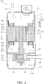
- FIG. 1 is a longitudinal cross-sectional view of a rotary compressor 101 according to the present example.
- the rotary compressor 101 primarily comprises a casing 10, a compression mechanism 15, a drive motor 16, a crankshaft 17, an intake tube 19, and a discharge tube 20.
- a casing 10 primarily comprises a casing 10, a compression mechanism 15, a drive motor 16, a crankshaft 17, an intake tube 19, and a discharge tube 20.
- Each of the constitutional elements of the rotary compressor 101 is described below.
- the casing 10 has a substantially tubular barrel casing part 11, a bowl-shaped upper wall part 12 hermetically welded to an upper-end part of the barrel casing part 11, and a bowl-shaped bottom wall part 13 hermetically welded to a lower-end part of the barrel casing part 11.
- the casing 10 is molded from a rigid material that does not readily deform or break when the pressure and temperature on the inner part and outer part of the casing 10 change.
- the casing 10 is arranged such that the axial direction of the substantially tubular shape of the barrel casing part 11 runs vertically.
- the bottom part of the casing 10 is provided with an oil reservoir part 10a in which a lubricating oil is accumulated.
- the lubricating oil is a refrigerating oil used in order to lubricate sliding parts inside the rotary compressor 101.
- the casing 10 primarily accommodates a compression mechanism 15, a drive motor 16 disposed above the compression mechanism 15, and a crankshaft 17 disposed along the vertical direction.
- the compression mechanism 15 and the drive motor 16 are linked via the crankshaft 17.
- the intake tube 19 and the discharge tube 20 are hermetically joined to the casing 10.
- the compression mechanism 15 is primarily configured from a front head 23, a cylinder 24, a rear head 25, and a piston 21.
- the front head 23, the cylinder 24, and the rear head 25 are integrally fastened by laser welding.
- the space above the compression mechanism 15 is a high-pressure space S1 into which refrigerant compressed by the compression mechanism 15 is discharged.
- the compression mechanism 15 has a compression chamber 40, which is a space surrounded by the front head 23, the cylinder 24, and the rear head 25.
- the compression chamber 40 is partitioned by the piston 21 into an intake chamber communicating with the intake tube 19 and a discharge chamber communicating with the high-pressure space S1.
- the piston 21 is fitted onto an eccentric shaft part 17a of the crankshaft 17. Due to axial rotation of the crankshaft 17, the piston 21 performs an orbiting motion in the compression chamber 40 about the rotational axis of the crankshaft 17. The orbiting motion of the piston 21 causes the volumes of the intake chamber and discharge chamber constituting the compression chamber 40 to vary.
- the drive motor 16 is a brushless DC motor accommodated inside the casing 10 and arranged above the compression mechanism 15.
- the drive motor 16 is primarily configured from a stator 51 secured to an inner peripheral surface of the casing 10, and a rotor 52 rotatably accommodated on the inner side of the stator 51 with an air gap provided therebetween.
- the drive motor 16 is a three-phase motor having six concentrated-winding coils, and furthermore is an adjustable-speed motor driven by an inverter control. The configuration of the drive motor 16 is described in detail later.
- the crankshaft 17 is disposed such that the central axis thereof runs vertically.
- the crankshaft 17 has an eccentric shaft part 17a.
- the eccentric shaft part 17a of the crankshaft 17 is linked to the piston 21 of the compression mechanism 15.
- the end part on the vertical-direction upper side of the crankshaft 17 is linked to the rotor 52 of the drive motor 16.
- the crankshaft 17 is rotatably supported by the front head 23 and the rear head 25.
- the intake tube 19 passes through the barrel casing part 11 of the casing 10.
- the end part of the intake tube 19 that is inside the casing 10 is fitted into the compression mechanism 15.
- the end part of the intake tube 19 that is outside the casing 10 is connected to the refrigerant circuit.
- the intake tube 19 is a tube for supplying refrigerant from the refrigerant circuit to the compression mechanism 15. (1-6) Discharge tube
- the discharge tube 20 passes through the upper wall part 12 of the casing 10.
- the end part of the discharge tube 20 that is inside the casing 10 is positioned above the drive motor 16 in the high-pressure space S1.
- the end part of the discharge tube 20 that is outside the casing 10 is connected to the refrigerant circuit.
- the discharge tube 20 is a tube for supplying refrigerant compressed by the compression mechanism 15 to the refrigerant circuit.
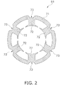
- FIG. 2 is a cross-sectional view of the stator 51, taken along line segment II-II in FIG. 1 .
- FIG. 3 is a top view of the stator 51 of the drive motor 16.
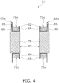
- FIG. 4 is a cross-sectional view, taken along line segment IV-IV in FIG. 3 .
- the stator 51 has a stator core 61, and a pair of insulators 62, 63 attached to the two vertical-direction end surfaces of the stator core 61, as shown in FIG. 4 .
- the insulator 62 is attached to the upper-side end surface of the stator core 61, and the insulator 63 is attached to the lower-side end surface of the stator core 61.
- the stator core 61 is secured to the casing 10. Specifically, the outer peripheral surface of the stator core 61 is welded to the inner peripheral surface of the casing 10. Three weld locations are provided to each of the two vertical-direction end parts of the stator core 61. The weld locations may be suitably determined in accordance with the weight and natural frequency of the stator core 61, and other such factors.
- the stator core 61 may be secured to the casing 10 by press-fitting and shrink-fitting.
- the stator core 61 has a tubular part 71, and six teeth 72, as shown in FIG. 2 .
- Each of the teeth 72 protrudes from the inner peripheral surface of the tubular part 71 radially inward from the tubular part 71.
- the radial direction of the tubular part 71 falls within a horizontal plane orthogonal to the vertical direction.
- the six teeth 72 are disposed at equal intervals along a circumferential direction of the tubular part 71.
- the six teeth 72 are disposed at positions having six-fold symmetry about a central axis of the tubular part 71.
- Each of the core cuts 73 is a groove forming a cutout along the central axis of the tubular part 71, from an upper-end surface of the tubular part 71 to a lower-end surface of the tubular part 71.
- Each of the core cuts 73 is positioned radially outside the tubular part 71, as viewed from the teeth 72.
- the six core cuts 73 are disposed at equal intervals along the circumferential direction of the tubular part 71.
- the six core cuts 73 are disposed at positions having six-fold symmetry about the central axis of the tubular part 71.
- Conducting wires are wound about the teeth 72 of the stator core 61, as well as the insulator 62, as shown in FIGS. 3 and 4 .
- a coil 72a is thereby formed on each of the teeth 72 of the stator core 61.
- the conducting wires wound about the teeth 72 and the insulator 62 are referred to below as "windings 64.”
- the windings 64 are wound separately about each of the teeth 72.
- the coils 72a are concentrated-winding coils.
- the windings 64 of each of the teeth 72 are connected to each other via crossover wires 65.
- Inter-coil spaces S2 are formed between every two adjacent coils 72a. Windings (not shown) corresponding to neutral points of the coils 72a are accommodated in insulation caps, and are inserted into the inter-coil spaces S2, which are the spaces between every two adjacent coils 72a.
- FIG. 5 is a top view of the insulator 62 attached to the upper-side end surface of the stator coil 61.
- the insulator 62 is an insulating body attached to the two vertical-direction end surfaces of the stator coil 61.
- the insulator 62 is molded from, e.g., a liquid crystal polymer (LCP), polybutylene terephthalate (PBT), polyphenylene sulfide (PPS), a polyimide, a polyester, or another highly heat-resistant resin.
- LCP liquid crystal polymer
- PBT polybutylene terephthalate
- PPS polyphenylene sulfide
- the insulator 62 has an annular part 62a and six projecting parts 62b, as shown in FIG. 5 .
- the annular part 62a is in contact with the upper-end surface of the tubular part 71 of the stator core 61.
- the projecting parts 62b protrude from an inner peripheral surface of the annular part 62a radially inward from the annular part 62a.
- Each of the projecting parts 62b is in contact with the upper-end surface of the teeth 72 of the stator core 61.
- the insulator 62 insulates the stator core 61 and the windings 64 of the coils 72a. The description given above can also be applied to the insulator 63 attached to the lower-side end surface of the stator core 61.
- FIG. 6 is an enlarged view of the insulator 62 shown in FIG. 4 .
- FIG. 6 also shows the barrel casing part 11 of the casing 10.
- an outer peripheral surface 62d of the insulator 62 is in contact with the crossover wires 65.
- An insulation sheet 66 is arranged between the outer peripheral surface 62d of the insulator 62 and an inner peripheral surface 11a of the barrel casing part 11.
- the crossover wires 65 are positioned between the insulation sheet 66 and the outer peripheral surface 62d of the insulator 62.
- the insulation sheet 66 is arranged between the crossover wires 65 and the casing 10, preventing electrical connection between the crossover wires 65 and the casing 10.
- FIG. 3 shows the crossover wires 65 and the insulation sheet 66 as hatched regions.
- FIG. 7 is an outline view of the insulation sheet 66 of the compressor 101.
- the insulation sheet 66 is tubular in shape.
- the material constituting the insulation sheet 66 is an insulating body made of resin, etc.
- the insulation sheet 66 is produced by forming a rectangular resin film into a rounded configuration and molding the film into a tubular shape.
- the resin film is, e.g., 0.1-1.0 mm thick.
- the diameter of the tubular shape of the insulation sheet 66 is set between the diameter of the outer peripheral surface 62d of the insulator 62 and the diameter of the inner peripheral surface 11a of the barrel casing part 11.
- the insulation sheet 66 is arranged between the casing 10 and the insulator 62 attached to the upper-side end surface of the stator core 61; however, in cases in which the crossover wires 65 are arranged below the stator core 61, the insulation sheet 66 may be arranged between the casing 10 and the insulator 63 attached to the lower-side end surface of the stator core 61.
- the rotor 52 is linked to the crankshaft 17, which passes vertically through the rotational center of the rotor 52.
- the rotor 52 is connected to the compression mechanism 15 with the crankshaft 17 interposed therebetween.
- the rotor 52 has a rotor core 52a configured from a plurality of metal plates that are stacked in the vertical direction, and a plurality of magnets 52b embedded in the rotor core 52a, as shown in FIG. 1 .
- the magnets 52b are disposed at equal intervals along the circumferential direction of the rotor core 52a.
- Driving of the drive motor 16 causes the rotor 52 to rotate and the crankshaft 17 to axially rotate. Due to the axial rotation of the crankshaft 17, the piston 21 of the compression mechanism 15 performs an orbiting motion in the compression chamber 40 about the rotational axis of the crankshaft 17.
- the orbiting motion of the piston 21 causes the volumes of the intake chamber and discharge chamber constituting the compression chamber 40 to vary.
- a low-pressure gas refrigerant is thereby taken into the intake chamber of the compression chamber 40 from the intake tube 19.
- the volume of the intake chamber is reduced by the orbiting motion of the piston 21; as a result, the refrigerant is compressed, and the intake chamber becomes a discharge chamber.
- the compressed, high-pressure gas refrigerant is discharged from the discharge chamber into the high-pressure space S1.
- the discharged compressed refrigerant passes vertically upward through the air gap, which is the space between the stator 51 and the rotor 52.
- the compressed refrigerant is then discharged outside the casing 10 from the discharge tube 20.
- the refrigerant compressed by the rotary compressor 101 is, e.g., R410A, R22, R32, or carbon dioxide.
- the lubricating oil that has accumulated in the oil reservoir part 10a at the bottom of the casing 10 is supplied to sliding parts of the compression mechanism 15, etc.
- the lubricating oil supplied to the sliding parts of the compression mechanism 15 flows into the compression chamber 40.
- the lubricating oil is formed into fine oil droplets that are mixed into the refrigerant gas. Therefore, the compressed refrigerant discharged from the compression mechanism 15 includes the lubricating oil.
- Some of the lubricating oil included in the compressed refrigerant separates from the refrigerant due to centrifugal force or the like caused by the flow of the refrigerant in the high-pressure space S1 above the drive motor 16, and adheres to the inner peripheral surface of the casing 10.
- the lubricating oil that has adhered to the inner peripheral surface of the casing 10 descends along the inner peripheral surface of the casing 10, and reaches a position at the height of the upper surface of the stator 51 of the drive motor 16.
- the lubricating oil then descends through the core cuts 73 of the stator core 61.
- the lubricating oil that has descended through the core cuts 73 finally returns to the oil reservoir part 10a.
- the rotary compressor 101 comprises the drive motor 16 having the concentrated-winding coils.
- the windings 64 of each of the coils 72a are connected to each other via the crossover wires 65.
- the crossover wires 65 are arranged so as to be wound about the insulator 62, which is positioned above the stator 51, while in contact with the outer peripheral surface 62d of the insulator 62.
- the insulation sheet 66 is arranged between the crossover wires 65 and the barrel casing part 11 of the casing 10.
- the tubular insulation sheet 66 is arranged by insertion between the outer peripheral surface 62d of the insulator 62 and the inner peripheral surface 11a of the barrel casing part 11.
- the insulation sheet 66 is an insulation member for preventing electrical connection between the crossover wires 65 and the casing 10.
- the distance between the crossover wires 65 and the casing 10 must be set equal to or greater than a legally stipulated distance, in order to suitably insulate the crossover wires 65 and the casing 10 from each other. In such a case, it is difficult to reduce the thickness of a back yoke, which is a toric portion on the outer side of the stator 51.
- the rotary compressor 101 arranging the insulation sheet 66 between the crossover wires 65 and the casing 10 makes it possible to reduce the distance between the crossover wires 65 and the casing 10. This makes it possible to reduce the thickness of the back yoke of the stator 51, and to make the drive motor 16 more compact.
- using the insulation sheet 66 makes it possible to make the rotary compressor 101 more compact. Even when the insulation sheet 66 is molded from a thin insulation member, and the temperature of the insulation sheet 66 rises during operation of the rotary compressor 101, the insulation sheet 66 does not have a large quantity of heat. Therefore, the insulation sheet 66 exerts substantially no adverse effect on the operation of the drive motor 16. Accordingly, the rotary compressor 101 can be made more compact without reducing the efficiency of the drive motor 16.
- the insulation sheet 66 has a tubular shape having only a side surface, as shown in FIG. 7 . Therefore, inserting the insulation sheet 66 into the gap between the outer peripheral surface 62d of the insulator 62 and the inner peripheral surface 11a of the barrel casing part 11 from above the insulator 62 makes it possible to arrange the insulation sheet 66 between the crossover wires 65 and the casing 10. Accordingly, since the insulation sheet 66 can readily be arranged, the rotary compressor 101 can be made more compact simply.
- the insulation sheet 66 is preferably molded from a heat-shrinkable material. Specifically, the insulation sheet 66 is preferably molded from an insulating body having heat-shrinkage properties. In this case, heating and shrinking the tubular insulation sheet 66 after arranging the insulation sheet 66 by insertion between the crossover wires 65 and the casing 10 makes it possible to secure the insulation sheet 66 to the insulator 62. Accordingly, using the heat-shrinkable insulation sheet 66 makes it possible to readily secure the insulation sheet 66 to the drive motor 16.
- the insulation sheet 66 has a tubular shape having only a side surface, as shown in FIG. 7 .
- FIG. 8 is an outline view of the insulation sheet 66 according to an embodiment of the present invention as a present modification of the present example.
- the insulation sheet 66 may be tubular in shape, and may have tabs 66a protruding from a lower end of the tubular shape.
- the tabs 66a of the insulation sheet 66 are portions sandwiched between the stator 51 and the insulator 62.
- FIG. 9 is a view that, in the present modification, corresponds to FIG. 6 .
- FIG. 9 shows the insulation sheet 66 having the tabs 66a sandwiched between an upper-end surface of the stator 51 and a bottom surface of the insulator 62.
- the insulation sheet 66 is arranged between the crossover wires 65 and the casing 10 while the tabs 66a of the insulation sheet 66 are inserted between the stator 51 and the insulator 62. Because the tabs 66a of the insulation sheet 66 are sandwiched between the stator 51 and the insulator 62, the tabs 66a prevent the insulation sheet 66 from separating from the stator 51. Accordingly, in the present modification, providing the tabs 66a to the insulation sheet 66 makes it possible to readily secure the insulation sheet 66 to the drive motor 16.
- the insulation sheet 66 has a tubular shape having only a side surface, as shown in FIG. 7 .
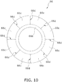
- FIG. 10 is an outline view of the insulation sheet 66 according to the present modification. As shown in FIG. 10 , the insulation sheet 66 may have an annular part 66b sandwiched between the stator 51 and the insulator 62 along the entire circumference of the stator 51.
- FIG. 10 is a development view of the insulation sheet 66 before the insulation sheet 66 is attached to the stator 51.
- the insulation sheet 66 has the annular part 66b, and a plurality of projecting parts 66c protruding outward from the annular part 66b. As shown in FIG.
- the projecting parts 66c may be formed by creating notches 66d along the radial direction of the annular part 66b, the notches being created in regions on the outer side of the annular part 66b.
- the notches 66d are provided at equal intervals along the circumferential direction of the annular part 66b.
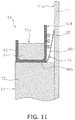
- FIG. 11 is a view that, in the present modification, corresponds to FIG. 6 .
- FIG. 11 shows the insulation sheet 66 having an annular part 66b sandwiched between an upper-end surface of the stator 51 and a bottom surface of the insulator 62.
- the projecting parts 66c of the insulation sheet 66 are arranged between the crossover wires 65 and the casing 10 while the annular part 66b of the insulation sheet 66 is inserted between the stator 51 and the insulator 62, as shown in FIG. 11 .
- the projecting parts 66c of the insulation sheet 66 are positioned between the crossover wires 65 and the casing 10.
- the projecting parts 66c stand upright with respect to the annular part 66b. Because the annular part 66b of the insulation sheet 66 is sandwiched between the stator 51 and the insulator 62, the annular part 66b prevents the insulation sheet 66 from separating from the stator 51. Accordingly, in the present modification, providing the annular part 66b and the projecting parts 66c to the insulation sheet 66 makes it possible to readily secure the insulation sheet 66 to the drive motor 16.
- the insulation sheet 66 it is not necessary to form the notches 66d in the insulation sheet 66. Even in such a case, it is possible to secure the insulation sheet 66 to the drive motor 16 such that the annular part 66b is sandwiched between the stator 51 and the insulator 62, and such that the projecting parts 66c are arranged between the crossover wires 65 and the casing 10.
- the insulation sheet 66 is arranged between the insulator 62 and the barrel casing part 11 of the casing 10.
- FIG. 12 is a view that, in the present modification, corresponds to FIG. 6 .
- the insulator 62 may have a protruding part 62e protruding toward the inner peripheral surface 11a of the barrel casing part 11.
- the insulation sheet 66 is arranged between the insulator 62 and the barrel casing part 11, and also between the stator 51 and the protruding part 62e.
- the insulation sheet 66 is arranged between the insulator 62 and the barrel casing part 11. As shown in FIG. 12 , the insulation sheet 66 is arranged below the protruding part 62e of the insulator 62, and above the upper-end surface of the stator 51. The protruding part 62e of the insulator 62 prevents the insulation sheet 66 from falling out of the gap between the insulator 62 and the barrel casing part 11. Accordingly, in the present modification, the insulation sheet 66 can be effectively prevented from separating from the drive motor 16.
- the insulation sheet 66 is arranged between the insulator 62 and the barrel casing part 11 of the casing 10.
- FIG. 13 is a view that, in the present modification, corresponds to FIG. 6 .
- a sheet-securing member 62f may be arranged between the insulator 62 and the barrel casing part 11.
- the sheet-securing member 62f is independent from the insulator 62.
- the sheet-securing member 62f may be capable of being attached to the insulator 62.
- the insulation sheet 66 is arranged between the insulator 62 and the barrel casing part 11, and also between the stator 51 and the sheet-securing member 62f.
- the insulation sheet 66 is arranged between the insulator 62 and the barrel casing part 11. As shown in FIG. 13 , the insulation sheet 66 is arranged below the sheet-securing member 62f and above the upper-end surface of the stator 51. The sheet-securing member 62f prevents the insulation sheet 66 from falling out of the gap between the insulator 62 and the barrel casing part 11. Accordingly, in the present modification, the insulation sheet 66 can be effectively prevented from separating from the drive motor 16.
- the insulation sheet 66 is configured from a single sheet; however, the insulation sheet 66 may instead be configured from a plurality of sheets.
- the insulation sheet 66 may be arranged such that a plurality of film-form insulation members constituting the insulation sheet 66 are inserted into a gap between the crossover wires 65 and the casing 10 from above the insulator 62, and the crossover wires 65 are insulated from the casing 10 through the entirety of the gap.
- the rotary compressor 101 is used as a compressor comprising the drive motor 16 in which the insulation sheet 66 is arranged between the crossover wires 65 and the casing 10; however, a scroll compressor and a reciprocating compressor, etc., may be used instead.
- the drive motor 16 has concentrated-winding coils; however, distributed-winding coils in which coil windings are wound across a plurality of the teeth 72 may be used instead.
- the compressor according to the present invention can be made more compact while ensuring the efficiency of the motor.
Landscapes
- Engineering & Computer Science (AREA)
- Power Engineering (AREA)
- Mechanical Engineering (AREA)
- General Engineering & Computer Science (AREA)
- Insulation, Fastening Of Motor, Generator Windings (AREA)
- Compressor (AREA)
- Applications Or Details Of Rotary Compressors (AREA)
Claims (5)
- Verdichter (101), mit:einem Gehäuse (10);einem Verdichtungsmechanismus (15), der innerhalb des Gehäuses angeordnet ist; undeinem Motor (16), der innerhalb des Gehäuses angeordnet ist, wobei der Motor den Verdichtungsmechanismus antreibt, wobei der Motor ein Motor mit konzentrierter Wicklung ist, der einen Stator (51), der eine Vielzahl von Zähnen (72) aufweist, und einen Isolierkörper (62) benachbart zum Stator aufweist, wobei Wicklungen (64) mit dem dazwischen angeordneten Isolierkörper um die Zähne gewickelt sind, wobei die Außenumfangsfläche (62d) des Isolierkörpers mit Kreuzungsdrähten (65) der Wicklungen in Kontakt steht;gekennzeichnet durcheine Isolationslage (66), die zwischen der Außenumfangsfläche des Isolierkörpers und der Innenumfangsfläche (11a) des Gehäuses und außerdem zwischen dem Gehäuse und den Kreuzungsdrähten angeordnet ist, so dass die Kreuzungsdrähte zwischen der Isolationslage und der Außenumfangsfläche des Isolierkörpers angeordnet sind;wobeidie Isolationslage in ihrer Form röhrenförmig ist; unddie Isolationslage Zungen (66a) aufweist, die zwischen dem Stator und dem Isolierkörper eingelegt sind.
- Verdichter nach Anspruch 1, wobei
die Isolationslage aus einem wärmeschrumpfbaren Material geformt ist. - Verdichter (101), mit:einem Gehäuse (10);einem Verdichtungsmechanismus (15), der innerhalb des Gehäuses angeordnet ist; undeinem Motor (16), der innerhalb des Gehäuses angeordnet ist, wobei der Motor den Verdichtungsmechanismus antreibt,wobei der Motor ein Motor mit konzentrierter Wicklung ist,der einen Stator (51), der eine Vielzahl von Zähnen (72) aufweist, und einen Isolierkörper (62) benachbart zum Stator aufweist, wobei Wicklungen (64) mit dem dazwischen angeordneten Isolierkörper um die Zähne gewickelt sind,wobei die Außenumfangsfläche (62d) des Isolierkörpers mit Kreuzungsdrähten (65) der Wicklungen in Kontakt steht;gekennzeichnet durcheine Isolationslage (66), die zwischen der Außenumfangsfläche des Isolierkörpers und der Innenumfangsfläche (11a) des Gehäuses und außerdem zwischen dem Gehäuse und den Kreuzungsdrähten angeordnet ist, so dass die Kreuzungsdrähte zwischen der Isolationslage undder Außenumfangsfläche des Isolierkörpers angeordnet sind;wobeidie Isolationslage einen ringförmigen Teil (66b) aufweist,der zwischen dem Stator und dem Isolierkörper über den gesamten Umfang des Stator eingelegt ist.
- Verdichter (101), mit:einem Gehäuse (10);einem Verdichtungsmechanismus (15), der innerhalb des Gehäuses angeordnet ist; undeinem Motor (16), der innerhalb des Gehäuses angeordnet ist, wobei der Motor den Verdichtungsmechanismus antreibt, wobei der Motor ein Motor mit konzentrierter Wicklung ist, der einen Stator (51), der eine Vielzahl von Zähnen (72) aufweist, und einen Isolierkörper (62) benachbart zum Stator aufweist, wobei Wicklungen (64) mit dem dazwischen angeordneten Isolierkörper um die Zähne gewickelt sind,wobei die Außenumfangsfläche (62d) des Isolierkörpers mit Kreuzungsdrähten (65) der Wicklungen in Kontakt steht;gekennzeichnet durcheine Isolationslage (66), die zwischen der Außenumfangsfläche des Isolierkörpers und der Innenumfangsfläche (11a) des Gehäuses und außerdem zwischen dem Gehäuse und den Kreuzungsdrähten angeordnet ist, so dass die Kreuzungsdrähte zwischen der Isolationslage undder Außenumfangsfläche des Isolierkörpers angeordnet sind;wobeider Isolierkörper einen vorstehenden Teil (62e) aufweist,der zum Gehäuse vorsteht; unddie Isolationslage auch zwischen dem Stator und dem vorstehenden Teil angeordnet ist.
- Verdichter (101), mit:einem Gehäuse (10);einem Verdichtungsmechanismus (15), der innerhalb des Gehäuses angeordnet ist; undeinem Motor (16), der innerhalb des Gehäuses angeordnet ist, wobei der Motor den Verdichtungsmechanismus antreibt, wobei der Motor ein Motor mit konzentrierter Wicklung ist, der einen Stator (51), der eine Vielzahl von Zähnen (72) aufweist, und einen Isolierkörper (62) benachbart zum Stator aufweist, wobei Wicklungen (64) mit dem dazwischen angeordneten Isolierkörper um die Zähne gewickelt sind, wobei die Außenumfangsfläche (62d) des Isolierkörpers mit Kreuzungsdrähten (65) der Wicklungen in Kontakt steht;gekennzeichnet durcheine Isolationslage (66), die zwischen derAußenumfangsfläche des Isolierkörpers und der Innenumfangsfläche (11a) des Gehäuses und außerdem zwischen dem Gehäuse und den Kreuzungsdrähten angeordnet ist, so dass die Kreuzungsdrähte zwischen der Isolationslage undder Außenumfangsfläche des Isolierkörpers angeordnet sind;undein Lagensicherungselement (62f), das zwischen dem Isolierkörper und dem Gehäuse angeordnet ist;wobeidie Isolationslage auch zwischen dem Stator und dem Lagensicherungselement angeordnet ist.
Applications Claiming Priority (2)
| Application Number | Priority Date | Filing Date | Title |
|---|---|---|---|
| JP2013249160A JP5831533B2 (ja) | 2013-12-02 | 2013-12-02 | 圧縮機 |
| PCT/JP2014/081838 WO2015083687A1 (ja) | 2013-12-02 | 2014-12-02 | 圧縮機 |
Publications (3)
| Publication Number | Publication Date |
|---|---|
| EP3079236A1 EP3079236A1 (de) | 2016-10-12 |
| EP3079236A4 EP3079236A4 (de) | 2017-02-01 |
| EP3079236B1 true EP3079236B1 (de) | 2018-03-07 |
Family
ID=53273449
Family Applications (1)
| Application Number | Title | Priority Date | Filing Date |
|---|---|---|---|
| EP14868338.6A Active EP3079236B1 (de) | 2013-12-02 | 2014-12-02 | Verdichter |
Country Status (9)
| Country | Link |
|---|---|
| US (1) | US9608490B2 (de) |
| EP (1) | EP3079236B1 (de) |
| JP (1) | JP5831533B2 (de) |
| CN (1) | CN105993114B (de) |
| BR (1) | BR112016012145B1 (de) |
| ES (1) | ES2672008T3 (de) |
| MX (1) | MX351459B (de) |
| MY (1) | MY164325A (de) |
| WO (1) | WO2015083687A1 (de) |
Families Citing this family (7)
| Publication number | Priority date | Publication date | Assignee | Title |
|---|---|---|---|---|
| JP5831533B2 (ja) | 2013-12-02 | 2015-12-09 | ダイキン工業株式会社 | 圧縮機 |
| JP2015226330A (ja) * | 2014-05-26 | 2015-12-14 | 日立アプライアンス株式会社 | ポンプ駆動用モータとそれを用いたポンプ装置 |
| JP6849326B2 (ja) * | 2016-06-20 | 2021-03-24 | マブチモーター株式会社 | ステータ及びモータ |
| JP2020188640A (ja) * | 2019-05-17 | 2020-11-19 | パナソニックIpマネジメント株式会社 | 冷凍サイクル装置 |
| JP6844676B1 (ja) * | 2019-11-29 | 2021-03-17 | ダイキン工業株式会社 | スクロール圧縮機 |
| CN112701832B (zh) * | 2020-11-12 | 2022-07-19 | 奇瑞新能源汽车股份有限公司 | 定子绝缘罩、电机定子及电机 |
| CN114795658B (zh) * | 2022-03-11 | 2023-05-16 | 河北医科大学第二医院 | 一种带有负压装置的vsd贴 |
Family Cites Families (13)
| Publication number | Priority date | Publication date | Assignee | Title |
|---|---|---|---|---|
| JP2875666B2 (ja) | 1991-11-18 | 1999-03-31 | 松下精工株式会社 | 樹脂モールドモータの固定子 |
| JPH11178264A (ja) * | 1997-12-10 | 1999-07-02 | Fuji Electric Co Ltd | 低圧電気機械用の電機子巻線 |
| DE19902837C1 (de) * | 1999-01-20 | 2000-08-10 | Siemens Ag | Rotierende elektrische Maschine mit permanenterregtem Rotor |
| JP2002044892A (ja) | 2000-07-27 | 2002-02-08 | Matsushita Electric Ind Co Ltd | 電動機およびそれを搭載した電動圧縮機 |
| US6445095B1 (en) * | 2001-01-11 | 2002-09-03 | Ford Global Technologies, Inc. | Electric machine with laminated cooling rings |
| JP4270307B2 (ja) * | 2007-06-25 | 2009-05-27 | トヨタ自動車株式会社 | 渡り線モジュール |
| JP5214934B2 (ja) * | 2007-09-19 | 2013-06-19 | 株式会社小松製作所 | 電動モータ |
| JP4957614B2 (ja) * | 2008-03-28 | 2012-06-20 | ダイキン工業株式会社 | ステータ、モータおよび圧縮機 |
| JP5273448B2 (ja) * | 2008-06-17 | 2013-08-28 | 日本電産株式会社 | モータ |
| CN201323475Y (zh) * | 2009-03-06 | 2009-10-07 | 黄石艾博科技发展有限公司 | 带外保护绝缘圈的定子 |
| JP2012196086A (ja) * | 2011-03-17 | 2012-10-11 | Daikin Ind Ltd | ステータ、モータ、圧縮機、および、ステータの組立方法 |
| JP5607708B2 (ja) * | 2012-12-04 | 2014-10-15 | ファナック株式会社 | 電動機の固定子 |
| JP5831533B2 (ja) | 2013-12-02 | 2015-12-09 | ダイキン工業株式会社 | 圧縮機 |
-
2013
- 2013-12-02 JP JP2013249160A patent/JP5831533B2/ja active Active
-
2014
- 2014-12-02 ES ES14868338.6T patent/ES2672008T3/es active Active
- 2014-12-02 CN CN201480065368.4A patent/CN105993114B/zh active Active
- 2014-12-02 MY MYPI2016701937A patent/MY164325A/en unknown
- 2014-12-02 BR BR112016012145-7A patent/BR112016012145B1/pt active IP Right Grant
- 2014-12-02 WO PCT/JP2014/081838 patent/WO2015083687A1/ja not_active Ceased
- 2014-12-02 US US15/100,576 patent/US9608490B2/en not_active Expired - Fee Related
- 2014-12-02 MX MX2016006881A patent/MX351459B/es active IP Right Grant
- 2014-12-02 EP EP14868338.6A patent/EP3079236B1/de active Active
Non-Patent Citations (1)
| Title |
|---|
| None * |
Also Published As
| Publication number | Publication date |
|---|---|
| BR112016012145B1 (pt) | 2021-12-28 |
| CN105993114B (zh) | 2017-09-19 |
| BR112016012145A2 (pt) | 2017-08-08 |
| CN105993114A (zh) | 2016-10-05 |
| JP5831533B2 (ja) | 2015-12-09 |
| US9608490B2 (en) | 2017-03-28 |
| JP2015107019A (ja) | 2015-06-08 |
| WO2015083687A1 (ja) | 2015-06-11 |
| MX2016006881A (es) | 2016-12-15 |
| EP3079236A4 (de) | 2017-02-01 |
| US20160315517A1 (en) | 2016-10-27 |
| EP3079236A1 (de) | 2016-10-12 |
| MX351459B (es) | 2017-10-16 |
| MY164325A (en) | 2017-12-15 |
| ES2672008T3 (es) | 2018-06-12 |
Similar Documents
| Publication | Publication Date | Title |
|---|---|---|
| EP3079236A1 (de) | Verdichter | |
| CN103573578B (zh) | 电动压缩机 | |
| EP2112749B1 (de) | Motorbetriebener Verdichter | |
| US7772736B2 (en) | Permanent magnet synchronous motor, rotor of the same, and compressor using the same | |
| US20150188377A1 (en) | Compressor, motor included therein, and method for manufacturing the motor | |
| CN102301568B (zh) | 定子、电动机以及压缩机 | |
| CN120049645A (zh) | 电动机、压缩机以及空调 | |
| CN101494399A (zh) | 马达及具备该马达的马达一体型泵 | |
| US20090079292A1 (en) | Interphase insulating sheet of rotating electric machine, method for manufacturing interphase insulating sheet, and electric compressor | |
| US9853514B2 (en) | Interphase insulating sheets with voids at annular portions for rotating electric machine, rotating electric machine, and electric compressor for vehicle | |
| CN101617458A (zh) | 电动机和压缩机 | |
| JP7285097B2 (ja) | オープン巻線型モーター、圧縮機、および冷凍サイクル装置 | |
| CN101981784A (zh) | 定子、电动机及压缩机 | |
| EP3220514B1 (de) | Stator und motor | |
| JP2016217291A (ja) | 電動コンプレッサ及びその製造方法 | |
| JP2013243822A (ja) | ステータおよび圧縮機 | |
| CN111512522A (zh) | 电动压缩机 | |
| JP2016073137A (ja) | ステータおよびモータ | |
| EP4064527A1 (de) | Motor, verdichter und kühlzyklusvorrichtung | |
| JP2003324880A (ja) | 電動機及び圧縮機 | |
| JP2010246338A (ja) | 固定子、モータ及び圧縮機 | |
| KR20140070383A (ko) | 알루미늄 권선을 구비한 단상 유도 모터를 가진 스크롤 압축기 | |
| KR101987737B1 (ko) | 전동 압축기 | |
| JP5211713B2 (ja) | ステータ、モータおよび圧縮機 | |
| JP2018011394A (ja) | インシュレータ、および、インシュレータの製造方法 |
Legal Events
| Date | Code | Title | Description |
|---|---|---|---|
| PUAI | Public reference made under article 153(3) epc to a published international application that has entered the european phase |
Free format text: ORIGINAL CODE: 0009012 |
|
| 17P | Request for examination filed |
Effective date: 20160623 |
|
| AK | Designated contracting states |
Kind code of ref document: A1 Designated state(s): AL AT BE BG CH CY CZ DE DK EE ES FI FR GB GR HR HU IE IS IT LI LT LU LV MC MK MT NL NO PL PT RO RS SE SI SK SM TR |
|
| AX | Request for extension of the european patent |
Extension state: BA ME |
|
| A4 | Supplementary search report drawn up and despatched |
Effective date: 20170105 |
|
| RIC1 | Information provided on ipc code assigned before grant |
Ipc: H02K 3/38 20060101AFI20161223BHEP Ipc: H02K 3/52 20060101ALI20161223BHEP |
|
| DAX | Request for extension of the european patent (deleted) | ||
| GRAP | Despatch of communication of intention to grant a patent |
Free format text: ORIGINAL CODE: EPIDOSNIGR1 |
|
| STAA | Information on the status of an ep patent application or granted ep patent |
Free format text: STATUS: GRANT OF PATENT IS INTENDED |
|
| INTG | Intention to grant announced |
Effective date: 20170929 |
|
| RIN1 | Information on inventor provided before grant (corrected) |
Inventor name: AOTA, KEIJI Inventor name: ISHIZAKI, AKINOBU |
|
| GRAS | Grant fee paid |
Free format text: ORIGINAL CODE: EPIDOSNIGR3 |
|
| GRAA | (expected) grant |
Free format text: ORIGINAL CODE: 0009210 |
|
| STAA | Information on the status of an ep patent application or granted ep patent |
Free format text: STATUS: THE PATENT HAS BEEN GRANTED |
|
| AK | Designated contracting states |
Kind code of ref document: B1 Designated state(s): AL AT BE BG CH CY CZ DE DK EE ES FI FR GB GR HR HU IE IS IT LI LT LU LV MC MK MT NL NO PL PT RO RS SE SI SK SM TR |
|
| REG | Reference to a national code |
Ref country code: GB Ref legal event code: FG4D |
|
| REG | Reference to a national code |
Ref country code: CH Ref legal event code: EP Ref country code: AT Ref legal event code: REF Ref document number: 977542 Country of ref document: AT Kind code of ref document: T Effective date: 20180315 |
|
| REG | Reference to a national code |
Ref country code: IE Ref legal event code: FG4D |
|
| REG | Reference to a national code |
Ref country code: DE Ref legal event code: R096 Ref document number: 602014022211 Country of ref document: DE |
|
| REG | Reference to a national code |
Ref country code: ES Ref legal event code: FG2A Ref document number: 2672008 Country of ref document: ES Kind code of ref document: T3 Effective date: 20180612 |
|
| REG | Reference to a national code |
Ref country code: NL Ref legal event code: MP Effective date: 20180307 |
|
| REG | Reference to a national code |
Ref country code: LT Ref legal event code: MG4D |
|
| PG25 | Lapsed in a contracting state [announced via postgrant information from national office to epo] |
Ref country code: NO Free format text: LAPSE BECAUSE OF FAILURE TO SUBMIT A TRANSLATION OF THE DESCRIPTION OR TO PAY THE FEE WITHIN THE PRESCRIBED TIME-LIMIT Effective date: 20180607 Ref country code: HR Free format text: LAPSE BECAUSE OF FAILURE TO SUBMIT A TRANSLATION OF THE DESCRIPTION OR TO PAY THE FEE WITHIN THE PRESCRIBED TIME-LIMIT Effective date: 20180307 Ref country code: LT Free format text: LAPSE BECAUSE OF FAILURE TO SUBMIT A TRANSLATION OF THE DESCRIPTION OR TO PAY THE FEE WITHIN THE PRESCRIBED TIME-LIMIT Effective date: 20180307 Ref country code: CY Free format text: LAPSE BECAUSE OF FAILURE TO SUBMIT A TRANSLATION OF THE DESCRIPTION OR TO PAY THE FEE WITHIN THE PRESCRIBED TIME-LIMIT Effective date: 20180307 Ref country code: FI Free format text: LAPSE BECAUSE OF FAILURE TO SUBMIT A TRANSLATION OF THE DESCRIPTION OR TO PAY THE FEE WITHIN THE PRESCRIBED TIME-LIMIT Effective date: 20180307 |
|
| REG | Reference to a national code |
Ref country code: AT Ref legal event code: MK05 Ref document number: 977542 Country of ref document: AT Kind code of ref document: T Effective date: 20180307 |
|
| PG25 | Lapsed in a contracting state [announced via postgrant information from national office to epo] |
Ref country code: BG Free format text: LAPSE BECAUSE OF FAILURE TO SUBMIT A TRANSLATION OF THE DESCRIPTION OR TO PAY THE FEE WITHIN THE PRESCRIBED TIME-LIMIT Effective date: 20180607 Ref country code: GR Free format text: LAPSE BECAUSE OF FAILURE TO SUBMIT A TRANSLATION OF THE DESCRIPTION OR TO PAY THE FEE WITHIN THE PRESCRIBED TIME-LIMIT Effective date: 20180608 Ref country code: SE Free format text: LAPSE BECAUSE OF FAILURE TO SUBMIT A TRANSLATION OF THE DESCRIPTION OR TO PAY THE FEE WITHIN THE PRESCRIBED TIME-LIMIT Effective date: 20180307 Ref country code: LV Free format text: LAPSE BECAUSE OF FAILURE TO SUBMIT A TRANSLATION OF THE DESCRIPTION OR TO PAY THE FEE WITHIN THE PRESCRIBED TIME-LIMIT Effective date: 20180307 Ref country code: RS Free format text: LAPSE BECAUSE OF FAILURE TO SUBMIT A TRANSLATION OF THE DESCRIPTION OR TO PAY THE FEE WITHIN THE PRESCRIBED TIME-LIMIT Effective date: 20180307 |
|
| PG25 | Lapsed in a contracting state [announced via postgrant information from national office to epo] |
Ref country code: PL Free format text: LAPSE BECAUSE OF FAILURE TO SUBMIT A TRANSLATION OF THE DESCRIPTION OR TO PAY THE FEE WITHIN THE PRESCRIBED TIME-LIMIT Effective date: 20180307 Ref country code: EE Free format text: LAPSE BECAUSE OF FAILURE TO SUBMIT A TRANSLATION OF THE DESCRIPTION OR TO PAY THE FEE WITHIN THE PRESCRIBED TIME-LIMIT Effective date: 20180307 Ref country code: AL Free format text: LAPSE BECAUSE OF FAILURE TO SUBMIT A TRANSLATION OF THE DESCRIPTION OR TO PAY THE FEE WITHIN THE PRESCRIBED TIME-LIMIT Effective date: 20180307 Ref country code: RO Free format text: LAPSE BECAUSE OF FAILURE TO SUBMIT A TRANSLATION OF THE DESCRIPTION OR TO PAY THE FEE WITHIN THE PRESCRIBED TIME-LIMIT Effective date: 20180307 Ref country code: NL Free format text: LAPSE BECAUSE OF FAILURE TO SUBMIT A TRANSLATION OF THE DESCRIPTION OR TO PAY THE FEE WITHIN THE PRESCRIBED TIME-LIMIT Effective date: 20180307 |
|
| PG25 | Lapsed in a contracting state [announced via postgrant information from national office to epo] |
Ref country code: AT Free format text: LAPSE BECAUSE OF FAILURE TO SUBMIT A TRANSLATION OF THE DESCRIPTION OR TO PAY THE FEE WITHIN THE PRESCRIBED TIME-LIMIT Effective date: 20180307 Ref country code: CZ Free format text: LAPSE BECAUSE OF FAILURE TO SUBMIT A TRANSLATION OF THE DESCRIPTION OR TO PAY THE FEE WITHIN THE PRESCRIBED TIME-LIMIT Effective date: 20180307 Ref country code: SK Free format text: LAPSE BECAUSE OF FAILURE TO SUBMIT A TRANSLATION OF THE DESCRIPTION OR TO PAY THE FEE WITHIN THE PRESCRIBED TIME-LIMIT Effective date: 20180307 Ref country code: SM Free format text: LAPSE BECAUSE OF FAILURE TO SUBMIT A TRANSLATION OF THE DESCRIPTION OR TO PAY THE FEE WITHIN THE PRESCRIBED TIME-LIMIT Effective date: 20180307 |
|
| REG | Reference to a national code |
Ref country code: DE Ref legal event code: R097 Ref document number: 602014022211 Country of ref document: DE |
|
| PG25 | Lapsed in a contracting state [announced via postgrant information from national office to epo] |
Ref country code: PT Free format text: LAPSE BECAUSE OF FAILURE TO SUBMIT A TRANSLATION OF THE DESCRIPTION OR TO PAY THE FEE WITHIN THE PRESCRIBED TIME-LIMIT Effective date: 20180709 |
|
| PLBE | No opposition filed within time limit |
Free format text: ORIGINAL CODE: 0009261 |
|
| STAA | Information on the status of an ep patent application or granted ep patent |
Free format text: STATUS: NO OPPOSITION FILED WITHIN TIME LIMIT |
|
| PG25 | Lapsed in a contracting state [announced via postgrant information from national office to epo] |
Ref country code: DK Free format text: LAPSE BECAUSE OF FAILURE TO SUBMIT A TRANSLATION OF THE DESCRIPTION OR TO PAY THE FEE WITHIN THE PRESCRIBED TIME-LIMIT Effective date: 20180307 |
|
| 26N | No opposition filed |
Effective date: 20181210 |
|
| PG25 | Lapsed in a contracting state [announced via postgrant information from national office to epo] |
Ref country code: SI Free format text: LAPSE BECAUSE OF FAILURE TO SUBMIT A TRANSLATION OF THE DESCRIPTION OR TO PAY THE FEE WITHIN THE PRESCRIBED TIME-LIMIT Effective date: 20180307 |
|
| REG | Reference to a national code |
Ref country code: CH Ref legal event code: PL |
|
| PG25 | Lapsed in a contracting state [announced via postgrant information from national office to epo] |
Ref country code: LU Free format text: LAPSE BECAUSE OF NON-PAYMENT OF DUE FEES Effective date: 20181202 Ref country code: MC Free format text: LAPSE BECAUSE OF FAILURE TO SUBMIT A TRANSLATION OF THE DESCRIPTION OR TO PAY THE FEE WITHIN THE PRESCRIBED TIME-LIMIT Effective date: 20180307 |
|
| REG | Reference to a national code |
Ref country code: IE Ref legal event code: MM4A |
|
| REG | Reference to a national code |
Ref country code: BE Ref legal event code: MM Effective date: 20181231 |
|
| PG25 | Lapsed in a contracting state [announced via postgrant information from national office to epo] |
Ref country code: IE Free format text: LAPSE BECAUSE OF NON-PAYMENT OF DUE FEES Effective date: 20181202 |
|
| PG25 | Lapsed in a contracting state [announced via postgrant information from national office to epo] |
Ref country code: BE Free format text: LAPSE BECAUSE OF NON-PAYMENT OF DUE FEES Effective date: 20181231 |
|
| PG25 | Lapsed in a contracting state [announced via postgrant information from national office to epo] |
Ref country code: LI Free format text: LAPSE BECAUSE OF NON-PAYMENT OF DUE FEES Effective date: 20181231 Ref country code: CH Free format text: LAPSE BECAUSE OF NON-PAYMENT OF DUE FEES Effective date: 20181231 |
|
| PG25 | Lapsed in a contracting state [announced via postgrant information from national office to epo] |
Ref country code: MT Free format text: LAPSE BECAUSE OF NON-PAYMENT OF DUE FEES Effective date: 20181202 |
|
| PG25 | Lapsed in a contracting state [announced via postgrant information from national office to epo] |
Ref country code: TR Free format text: LAPSE BECAUSE OF FAILURE TO SUBMIT A TRANSLATION OF THE DESCRIPTION OR TO PAY THE FEE WITHIN THE PRESCRIBED TIME-LIMIT Effective date: 20180307 |
|
| PG25 | Lapsed in a contracting state [announced via postgrant information from national office to epo] |
Ref country code: MK Free format text: LAPSE BECAUSE OF NON-PAYMENT OF DUE FEES Effective date: 20180307 Ref country code: HU Free format text: LAPSE BECAUSE OF FAILURE TO SUBMIT A TRANSLATION OF THE DESCRIPTION OR TO PAY THE FEE WITHIN THE PRESCRIBED TIME-LIMIT; INVALID AB INITIO Effective date: 20141202 |
|
| PG25 | Lapsed in a contracting state [announced via postgrant information from national office to epo] |
Ref country code: IS Free format text: LAPSE BECAUSE OF FAILURE TO SUBMIT A TRANSLATION OF THE DESCRIPTION OR TO PAY THE FEE WITHIN THE PRESCRIBED TIME-LIMIT Effective date: 20180707 |
|
| P01 | Opt-out of the competence of the unified patent court (upc) registered |
Effective date: 20230525 |
|
| PGFP | Annual fee paid to national office [announced via postgrant information from national office to epo] |
Ref country code: DE Payment date: 20251028 Year of fee payment: 12 |
|
| PGFP | Annual fee paid to national office [announced via postgrant information from national office to epo] |
Ref country code: GB Payment date: 20251030 Year of fee payment: 12 |
|
| PGFP | Annual fee paid to national office [announced via postgrant information from national office to epo] |
Ref country code: IT Payment date: 20251121 Year of fee payment: 12 |
|
| PGFP | Annual fee paid to national office [announced via postgrant information from national office to epo] |
Ref country code: FR Payment date: 20251117 Year of fee payment: 12 |
|
| PGFP | Annual fee paid to national office [announced via postgrant information from national office to epo] |
Ref country code: ES Payment date: 20260108 Year of fee payment: 12 |