EP3073591B1 - Bougie d'allumage - Google Patents
Bougie d'allumage Download PDFInfo
- Publication number
- EP3073591B1 EP3073591B1 EP14863887.7A EP14863887A EP3073591B1 EP 3073591 B1 EP3073591 B1 EP 3073591B1 EP 14863887 A EP14863887 A EP 14863887A EP 3073591 B1 EP3073591 B1 EP 3073591B1
- Authority
- EP
- European Patent Office
- Prior art keywords
- tip
- surface layer
- front surface
- body portion
- main body
- Prior art date
- Legal status (The legal status is an assumption and is not a legal conclusion. Google has not performed a legal analysis and makes no representation as to the accuracy of the status listed.)
- Active
Links
- 239000002344 surface layer Substances 0.000 claims description 175
- 239000000203 mixture Substances 0.000 claims description 61
- 230000002093 peripheral effect Effects 0.000 claims description 28
- 238000002844 melting Methods 0.000 claims description 23
- 239000000470 constituent Substances 0.000 claims description 21
- 230000008018 melting Effects 0.000 claims description 19
- 230000003628 erosive effect Effects 0.000 description 70
- 230000002159 abnormal effect Effects 0.000 description 69
- 229910052751 metal Inorganic materials 0.000 description 59
- 239000002184 metal Substances 0.000 description 58
- 239000000463 material Substances 0.000 description 51
- 238000007747 plating Methods 0.000 description 37
- 238000000034 method Methods 0.000 description 36
- 239000012212 insulator Substances 0.000 description 33
- 238000012360 testing method Methods 0.000 description 33
- 239000011162 core material Substances 0.000 description 29
- 238000003466 welding Methods 0.000 description 29
- 239000010410 layer Substances 0.000 description 25
- QVGXLLKOCUKJST-UHFFFAOYSA-N atomic oxygen Chemical compound [O] QVGXLLKOCUKJST-UHFFFAOYSA-N 0.000 description 24
- 229910052760 oxygen Inorganic materials 0.000 description 24
- 239000001301 oxygen Substances 0.000 description 24
- 238000009792 diffusion process Methods 0.000 description 22
- 239000007789 gas Substances 0.000 description 19
- 238000002485 combustion reaction Methods 0.000 description 18
- 238000004519 manufacturing process Methods 0.000 description 17
- 230000003647 oxidation Effects 0.000 description 16
- 238000007254 oxidation reaction Methods 0.000 description 16
- 230000002829 reductive effect Effects 0.000 description 15
- 239000000843 powder Substances 0.000 description 13
- 238000009760 electrical discharge machining Methods 0.000 description 12
- 238000010438 heat treatment Methods 0.000 description 11
- 230000008569 process Effects 0.000 description 11
- 229910000990 Ni alloy Inorganic materials 0.000 description 10
- 230000000694 effects Effects 0.000 description 10
- 239000000446 fuel Substances 0.000 description 10
- 238000004458 analytical method Methods 0.000 description 8
- 238000011156 evaluation Methods 0.000 description 7
- 239000012535 impurity Substances 0.000 description 7
- 230000009467 reduction Effects 0.000 description 7
- 230000008859 change Effects 0.000 description 6
- 238000010494 dissociation reaction Methods 0.000 description 6
- 230000005593 dissociations Effects 0.000 description 6
- 238000005491 wire drawing Methods 0.000 description 6
- 238000009713 electroplating Methods 0.000 description 5
- 230000004927 fusion Effects 0.000 description 5
- 238000002347 injection Methods 0.000 description 5
- 239000007924 injection Substances 0.000 description 5
- 238000012856 packing Methods 0.000 description 5
- 229910000575 Ir alloy Inorganic materials 0.000 description 4
- 229910001260 Pt alloy Inorganic materials 0.000 description 4
- 229910018967 Pt—Rh Inorganic materials 0.000 description 4
- 229910045601 alloy Inorganic materials 0.000 description 4
- 239000000956 alloy Substances 0.000 description 4
- 229910052782 aluminium Inorganic materials 0.000 description 4
- 238000005229 chemical vapour deposition Methods 0.000 description 4
- 230000007423 decrease Effects 0.000 description 4
- 239000010970 precious metal Substances 0.000 description 4
- 239000002994 raw material Substances 0.000 description 4
- 229910052710 silicon Inorganic materials 0.000 description 4
- 229910052802 copper Inorganic materials 0.000 description 3
- 238000002788 crimping Methods 0.000 description 3
- 229910052741 iridium Inorganic materials 0.000 description 3
- 229910052742 iron Inorganic materials 0.000 description 3
- 238000005259 measurement Methods 0.000 description 3
- 230000007246 mechanism Effects 0.000 description 3
- 239000002923 metal particle Substances 0.000 description 3
- 230000001590 oxidative effect Effects 0.000 description 3
- 230000036961 partial effect Effects 0.000 description 3
- 239000002245 particle Substances 0.000 description 3
- 238000005240 physical vapour deposition Methods 0.000 description 3
- 229910052697 platinum Inorganic materials 0.000 description 3
- 238000005245 sintering Methods 0.000 description 3
- 238000004544 sputter deposition Methods 0.000 description 3
- 229910020598 Co Fe Inorganic materials 0.000 description 2
- 229910000881 Cu alloy Inorganic materials 0.000 description 2
- 229910001209 Low-carbon steel Inorganic materials 0.000 description 2
- 230000002411 adverse Effects 0.000 description 2
- 238000005275 alloying Methods 0.000 description 2
- 239000000919 ceramic Substances 0.000 description 2
- 238000007772 electroless plating Methods 0.000 description 2
- 238000004453 electron probe microanalysis Methods 0.000 description 2
- 238000004993 emission spectroscopy Methods 0.000 description 2
- 238000001125 extrusion Methods 0.000 description 2
- 238000005242 forging Methods 0.000 description 2
- 239000011521 glass Substances 0.000 description 2
- 229910052737 gold Inorganic materials 0.000 description 2
- 238000005098 hot rolling Methods 0.000 description 2
- 238000007733 ion plating Methods 0.000 description 2
- 239000007769 metal material Substances 0.000 description 2
- 238000012986 modification Methods 0.000 description 2
- 230000004048 modification Effects 0.000 description 2
- 239000002244 precipitate Substances 0.000 description 2
- 229910052709 silver Inorganic materials 0.000 description 2
- 239000000126 substance Substances 0.000 description 2
- 239000000454 talc Substances 0.000 description 2
- 229910052623 talc Inorganic materials 0.000 description 2
- 229910001316 Ag alloy Inorganic materials 0.000 description 1
- 229910000831 Steel Inorganic materials 0.000 description 1
- 230000001133 acceleration Effects 0.000 description 1
- 238000009825 accumulation Methods 0.000 description 1
- PNEYBMLMFCGWSK-UHFFFAOYSA-N aluminium oxide Inorganic materials [O-2].[O-2].[O-2].[Al+3].[Al+3] PNEYBMLMFCGWSK-UHFFFAOYSA-N 0.000 description 1
- 230000015572 biosynthetic process Effects 0.000 description 1
- ZCDOYSPFYFSLEW-UHFFFAOYSA-N chromate(2-) Chemical compound [O-][Cr]([O-])(=O)=O ZCDOYSPFYFSLEW-UHFFFAOYSA-N 0.000 description 1
- 230000007797 corrosion Effects 0.000 description 1
- 238000005260 corrosion Methods 0.000 description 1
- 238000005520 cutting process Methods 0.000 description 1
- 238000000151 deposition Methods 0.000 description 1
- 230000006866 deterioration Effects 0.000 description 1
- 230000002542 deteriorative effect Effects 0.000 description 1
- 239000006185 dispersion Substances 0.000 description 1
- 238000006073 displacement reaction Methods 0.000 description 1
- 238000011049 filling Methods 0.000 description 1
- 229910052735 hafnium Inorganic materials 0.000 description 1
- 229910001026 inconel Inorganic materials 0.000 description 1
- 238000007737 ion beam deposition Methods 0.000 description 1
- 238000000608 laser ablation Methods 0.000 description 1
- 238000004518 low pressure chemical vapour deposition Methods 0.000 description 1
- 229910052748 manganese Inorganic materials 0.000 description 1
- 229910001092 metal group alloy Inorganic materials 0.000 description 1
- 238000002488 metal-organic chemical vapour deposition Methods 0.000 description 1
- 238000002156 mixing Methods 0.000 description 1
- 238000001451 molecular beam epitaxy Methods 0.000 description 1
- 229910052750 molybdenum Inorganic materials 0.000 description 1
- 229910052759 nickel Inorganic materials 0.000 description 1
- 229910052758 niobium Inorganic materials 0.000 description 1
- 229910052755 nonmetal Inorganic materials 0.000 description 1
- 229910052698 phosphorus Inorganic materials 0.000 description 1
- 238000000623 plasma-assisted chemical vapour deposition Methods 0.000 description 1
- 229910000923 precious metal alloy Inorganic materials 0.000 description 1
- 238000003825 pressing Methods 0.000 description 1
- 239000011253 protective coating Substances 0.000 description 1
- 230000001681 protective effect Effects 0.000 description 1
- 230000001105 regulatory effect Effects 0.000 description 1
- 229910052702 rhenium Inorganic materials 0.000 description 1
- 229910052703 rhodium Inorganic materials 0.000 description 1
- 229910052707 ruthenium Inorganic materials 0.000 description 1
- 239000010959 steel Substances 0.000 description 1
- 229910052715 tantalum Inorganic materials 0.000 description 1
- 229910052721 tungsten Inorganic materials 0.000 description 1
- 238000001771 vacuum deposition Methods 0.000 description 1
Images


Classifications
-
- H—ELECTRICITY
- H01—ELECTRIC ELEMENTS
- H01T—SPARK GAPS; OVERVOLTAGE ARRESTERS USING SPARK GAPS; SPARKING PLUGS; CORONA DEVICES; GENERATING IONS TO BE INTRODUCED INTO NON-ENCLOSED GASES
- H01T13/00—Sparking plugs
- H01T13/20—Sparking plugs characterised by features of the electrodes or insulation
- H01T13/39—Selection of materials for electrodes
-
- B—PERFORMING OPERATIONS; TRANSPORTING
- B32—LAYERED PRODUCTS
- B32B—LAYERED PRODUCTS, i.e. PRODUCTS BUILT-UP OF STRATA OF FLAT OR NON-FLAT, e.g. CELLULAR OR HONEYCOMB, FORM
- B32B15/00—Layered products comprising a layer of metal
- B32B15/01—Layered products comprising a layer of metal all layers being exclusively metallic
- B32B15/018—Layered products comprising a layer of metal all layers being exclusively metallic one layer being formed of a noble metal or a noble metal alloy
-
- C—CHEMISTRY; METALLURGY
- C22—METALLURGY; FERROUS OR NON-FERROUS ALLOYS; TREATMENT OF ALLOYS OR NON-FERROUS METALS
- C22C—ALLOYS
- C22C19/00—Alloys based on nickel or cobalt
- C22C19/03—Alloys based on nickel or cobalt based on nickel
-
- C—CHEMISTRY; METALLURGY
- C22—METALLURGY; FERROUS OR NON-FERROUS ALLOYS; TREATMENT OF ALLOYS OR NON-FERROUS METALS
- C22C—ALLOYS
- C22C19/00—Alloys based on nickel or cobalt
- C22C19/03—Alloys based on nickel or cobalt based on nickel
- C22C19/05—Alloys based on nickel or cobalt based on nickel with chromium
- C22C19/058—Alloys based on nickel or cobalt based on nickel with chromium without Mo and W
-
- C—CHEMISTRY; METALLURGY
- C22—METALLURGY; FERROUS OR NON-FERROUS ALLOYS; TREATMENT OF ALLOYS OR NON-FERROUS METALS
- C22C—ALLOYS
- C22C5/00—Alloys based on noble metals
- C22C5/04—Alloys based on a platinum group metal
Definitions
- This invention relates to a spark plug.
- This invention especially relates to the spark plug that includes a tip on at least one of a center electrode and a ground electrode.
- a spark plug is used to ignite an internal combustion engine such as a vehicle engine.
- the spark plug includes a tubular metal shell, a tubular insulator, a center electrode, and a ground electrode.
- the insulator is arranged in an inner hole of this metal shell.
- the center electrode is arranged at the inner hole on a distal end side of the insulator.
- One end of the ground electrode is bonded to the distal end side of the metal shell.
- a spark discharge gap is provided between the other end of the ground electrode and the center electrode.
- the spark plug is spark-discharged at the spark discharge gap, which is formed between the distal end portion of the center electrode and the distal end portion of the ground electrode, in a combustion chamber of the internal combustion engine.
- the spark plug burns a fuel filled up in the combustion chamber.
- a Ni alloy or a similar material is generally used as a material forming the center electrode and the ground electrode.
- the Ni alloy is slightly inferior to a precious metal alloy whose main constituent is a precious metal such as Pt and Ir.
- the Ni alloy is preferably used as the material forming the ground electrode and the center electrode.
- the material forming the tips As the material forming the tips, a material whose main constituent is a precious metal excellent in the oxidation resistance and spark erosion resistance is often used.
- the material includes Ir, an Ir alloy, a Pt alloy, or a similar material.
- a tip that includes a protective coating layer or a similar layer at a surface of a core material whose main constituent is Ir (for example, see JP-A-2004-31300 and JP-A-2012-38733 ).
- the direct-injection gasoline engine directly injects a fuel around a plug in a fuel chamber.
- the lean burn engine decreases a mixing ratio of the fuel to the air to allow burning under high oxygen concentration atmosphere.
- Such engine requires a spark plug to have oxidation resistance. Accordingly, as a material that forms tips, which are formed at a center electrode and a ground electrode, a Pt alloy, which is known for excellent oxidation resistance, has been considered to ensure providing durability more than an Ir alloy, which is known for excellent spark erosion resistance. In particular, a Pt-Rh alloy, which is formed by containing Rh to Pt, where the oxidation resistance and the spark erosion resistance are improved has been considered as preferable.
- JP-A-2002-359050 discloses abnormal erosion occurred in the Ir alloy.
- the abnormal erosion at the side surface of the tip made of the Pt-Rh alloy differs from the abnormal erosion of JP-A-2002-359050 in a mechanism of the erosion.
- the precious metal tip containing Ir and 20 mass% of Rh, which is disclosed in JP-A-2002-359050 "generates abnormal erosion in the form along arc hollowing an outer peripheral side surface other than a discharge surface of a discharge portion" (paragraph number 0005).
- the tip made of the Pt-Rh alloy generates the abnormal erosion in the form of like the one entire side surface of tip dissipating.
- US-A1-2007/0236123 discloses a spark plug according to the preamble of claim 1 including a protective material to prevent corrosion of the base material of the electrodes.
- An object of this invention is to provide a spark plug featuring excellent durability.
- the spark plug includes a tip on at least one of a center electrode and a ground electrode.
- the spark plug with excellent durability can be achieved by reducing abnormal erosion of the tip.
- the invention provides a spark plug as defined by the appended claims.
- a tip disposed at least at one of a center electrode and a ground electrode is at least disposed at an outer peripheral surface (may also be referred to as a side surface) in a radial direction of an axial line.
- the axial line extends in a direction from a center of a main body portion to a gap among a surface of a main body portion having the composition.
- the tip includes a front surface layer.
- the front surface layer contains Ni of 8 mass% or more and has a thickness of 2 ⁇ m or more.
- the spark plug Even if the spark plug is used in a combustion chamber at a high temperature and high oxygen concentration, intake air gas is likely to directly hit a surface of the tip, and the tip is placed under conditions where the oxygen concentration and a temperature at periphery of the tip widely change, by reducing abnormal erosion at a side surface of the tip, the spark plug featuring excellent durability can be provided.
- Fig. 1 shows a spark plug of a spark plug of one embodiment according to this invention.
- Fig. 1 is a partial cross-sectional overall explanatory view of a spark plug 1 of the spark plug of one embodiment according to this invention.
- Fig. 1 describes a lower side of the paper, that is, a side where a ground electrode, which will be described later, is disposed as a distal end direction of an axial line O and an upper side of the paper as a rear end direction of the axial line O.
- This spark plug 1 includes an approximately cylindrical-shaped insulator 3, an approximately rod-shaped center electrode 4, a terminal metal fitting 5, a connecting portion 6, an approximately cylindrical-shaped metal shell 7, and a ground electrode 8.
- the insulator 3 has an axial hole 2 extending in the axial line O direction.
- the center electrode 4 is disposed at the distal end side in the axial hole 2.
- the terminal metal fitting 5 is disposed at the rear end side in the axial hole 2.
- the connecting portion 6 electrically connects the center electrode 4 and the terminal metal fitting 5 in the axial hole 2.
- the metal shell 7 holds the insulator 3.
- the one end portion of the ground electrode 8 is bonded to the distal end portion of the metal shell 7.
- the other end portion of the ground electrode 8 is disposed so as to be opposed to the center electrode 4 via the gap G.
- the ground electrode 8 has a tip 9 at a side surface at the distal end portion.
- the insulator 3 has the axial hole 2 extending in the axial line O direction and has the approximately cylindrical shape.
- the insulator 3 includes a rear end body portion 11, a large-diameter portion 12, a front end body portion 13, and an insulator nose portion 14.
- the rear end body portion 11 houses the terminal metal fitting 5 and insulates the terminal metal fitting 5 and the metal shell 7.
- the large-diameter portion 12 projects radially outward at the distal end side with respect to this rear end body portion.
- the front end body portion 13 houses the connecting portion 6 at the distal end side of this large-diameter portion 12.
- the front end body portion 13 has a smaller outer diameter than the large-diameter portion 12.
- the insulator nose portion 14 houses the center electrode 4 at the distal end side of this front end body portion 13.
- the insulator nose portion 14 has a smaller outer diameter and internal diameter than the front end body portion 13.
- Inner peripheral surfaces of the front end body portion 13 and the insulator nose portion 14 are connected via a shelf portion 15.
- a collar portion 16, which will be described later, of the center electrode 4 is disposed so as to be in contact with this shelf portion 15, securing the center electrode 4 to the inside of the axial hole 2.
- Outer peripheral surfaces of the front end body portion 13 and the insulator nose portion 14 are connected via a step part 17.
- a tapered portion 18, which will be described later, of the metal shell 7 is in contact with this step part 17 via a plate packing 19, securing the insulator 3 to the metal shell 7.
- the insulator 3 is secured to the metal shell 7 with the end portion of the insulator 3 in the distal end direction projected from the front end surface of the metal shell 7.
- the insulator 3 is preferably made of a material featuring mechanical strength, thermal strength, and electrical strength. As such material, for example, a ceramic sintered material mainly containing alumina can be listed.
- the axial hole 2 of the insulator 3 internally includes the center electrode 4 at the distal end side and the terminal metal fitting 5 at the rear end side. Between the center electrode 4 and the terminal metal fitting 5, the connecting portion 6 is disposed.
- the connecting portion 6 secures the center electrode 4 and the terminal metal fitting 5 to the inside of the axial hole 2 and electrically connects the center electrode 4 and the terminal metal fitting 5.
- the connecting portion 6 is formed of a resistor 21, a first seal body 22, and a second seal body 23.
- the resistor 21 is arranged to reduce propagation noise.
- the first seal body 22 is disposed between this resistor 21 and the center electrode 4.
- the second seal body 23 is disposed between this resistor 21 and the terminal metal fitting 5.
- the resistor 21 is formed by sintering a composition containing glass powder, non-metal conductive powder, metal powder, or similar powder. A resistance value of the resistor 21 is usually at 100 ⁇ or more.
- the first seal body 22 and the second seal body 23 are formed by sintering a composition containing the glass powder, the metal powder, or similar powder. A resistance value of the first seal body 22 and the second seal body 23 is usually 100 m ⁇ or less.
- the connecting portion 6 of this embodiment is formed of the resistor 21, the first seal body 22, and the second seal body 23. However, the connecting portion 6 may also be formed of at least one of the resistor 21, the first seal body 22, and the second seal body 23.
- the metal shell 7 has the approximately cylindrical shape.
- the metal shell 7 is formed so as to hold the insulator 3 by internally mounting the insulator 3.
- a screw portion 24 is formed at the outer peripheral surface of the metal shell 7 in the distal end direction. Using this screw portion 24, the spark plug 1 is mounted to a cylinder head (not shown) of the internal combustion engine.
- the metal shell 7 has a flange-shaped gas seal portion 25 at the rear end side of the screw portion 24.
- the metal shell 7 has a tool engagement portion 26 at the rear end side of the gas seal portion 25 and a crimping portion 27 at the rear end side of the tool engagement portion 26.
- the tool engagement portion 26 engages a tool such as a spanner and a wrench.
- ring-shaped packings 28 and 29 and a talc 30 are disposed, thus securing the insulator 3 to the metal shell 7.
- the distal end side of the inner peripheral surface of the screw portion 24 is disposed to have a space to the insulator nose portion 14.
- the tapered portion 18 and the step part 17 of the insulator 3 are in contact via the annular plate packing 19.
- the tapered portion 18 radially expands in a taper shape at the rear end side of a projection portion 32 projecting radially inward.
- the metal shell 7 can be made of a conductive steel material, for example, low-carbon steel.
- the terminal metal fitting 5 is a terminal nut to apply a voltage for spark discharge between the center electrode 4 and the ground electrode 8 from the outside to the center electrode 4.
- the terminal metal fitting 5 is inserted into the axial hole 2 with a part of the terminal metal fitting 5 exposed from the rear end side of the insulator 3 and is secured with the second seal body 23.
- the terminal metal fitting 5 can be made of a metallic material such as low-carbon steel.
- the center electrode 4 has a rear end portion 34 and a rod-shaped portion 35.
- the rear end portion 34 is in contact with the connecting portion 6.
- the rod-shaped portion 35 extends from the rear end portion 34 to the distal end side.
- the rear end portion 34 has the collar portion 16 projecting radially outward.
- the collar portion 16 is disposed in contact with the shelf portion 15 of the insulator 3. Further, between the inner peripheral surface of the axial hole 2 and the outer peripheral surface of the rear end portion 34, the first seal body 22 is filled up. Accordingly, the center electrode 4 is secured to the inside of the axial hole 2 of the insulator 3 with the distal end of the center electrode 4 projecting from the front end surface of the insulator 3, thus insulated and held to the metal shell 7.
- the rear end portion 34 and the rod-shaped portion 35 in the center electrode 4 can be made of a known material used for the center electrode 4 such as the Ni alloy.
- the center electrode 4 may be formed of an outer layer and a core portion.
- the outer layer is made of the Ni alloy or a similar material.
- the core portion is made of a material having coefficient of thermal conductivity higher than the Ni alloy.
- the core portion is formed so as to be concentrically embedded into an axial center portion at the inside of this outer layer.
- the material forming the core portion for example, Cu, a Cu alloy, Ag, an Ag alloy, and pure Ni can be listed.
- the ground electrode 8 is, for example, formed into an approximately prism shape.
- the one end portion of the ground electrode 8 is bonded to the distal end portion of the metal shell 7 and is flexed into an approximately L shape in mid-course.
- the other end portion of the ground electrode 8 is formed so as to be opposed to the distal end portion of the center electrode 4 via the gap G.
- the ground electrode 8 can be made of a known material used for the ground electrode 8, such as the Ni alloy. Similar to the center electrode 4, at an axis core portion of the ground electrode, the core portion made of the material having higher coefficient of thermal conductivity than the Ni alloy may be disposed.
- the tip 9 has a columnar shape in this embodiment and is disposed at only the ground electrode 8.
- the shape of the tip 9 is not especially limited.
- the tip 9 may be disposed only at the center electrode 4, or may be disposed at both the ground electrode 8 and the center electrode 4. It is only necessary that at least one of the tips, which are disposed at the ground electrode 8 and the center electrode 4, is formed of the tip made of the material having properties, which will be described later.
- the other tip may be made of the known material used as the tip.
- the tip 9 is bonded to the surface of the ground electrode 8 opposed to the center electrode 4 by an appropriate method such as a laser beam welding and a resistance welding.
- the gap G of the spark plug 1 of this embodiment is the shortest distance between the tip 9 disposed at the ground electrode 8 and the center electrode 4.
- This gap G is usually set to 0.3 to 1.5 mm.
- a spark plug 101 where side surfaces of a tip 309 disposed at a center electrode 104 and front end surfaces of tips 109 and 209 disposed at ground electrodes 108 and 208 are opposed.
- the shortest distance between the respective opposed surfaces where the tip 309 disposed at the center electrode 104 is opposed to the tip 109 disposed at the distal end portion of the ground electrode 108 becomes a gap G'. The spark discharge occurs at this gap G'.
- the tip 9 of this embodiment includes a main body portion 41 and a front surface layer 42.
- the front surface layer 42 is disposed at a side peripheral surface of this main body portion 41, that is, an outer peripheral surface (may also be referred to as the side surface) in the radial direction of an axial line A extending in a direction from the center of the main body portion 41 to the gap G.
- the composition of the main body portion 41 is Pt as a main constituent and 5 mass% or more of Rh and 0 mass% or more to less than 8 mass% of Ni.
- the composition of the main body portion 41 is preferably Pt as the main constituent and 5 mass% or more to 45 mass% or less of Rh and 0 mass% or more to 7 mass% or less of Ni.
- the composition of the main body portion 41 is more preferably Pt as the main constituent and 5 mass% or more to 45 mass% or less of Rh and 0 mass% or more to 1 mass% or less of Ni.
- the "main constituent” means a constituent whose mass proportion is the most among the constituents contained in the main body portion 41.
- the main body portion 41 whose composition is within the range features excellent spark erosion resistance and oxidation resistance.
- the tip 9 made of the Pt alloy has been considered to have excellent spark erosion resistance and oxidation resistance.
- the spark plug is operated in the combustion chamber at the high temperature and high oxygen concentration for long time, the intake air gas is likely to directly hit the surface of the tip 9, and the tip 9 is placed under the conditions where the oxygen concentration and the temperature at periphery of the tip 9 widely change. This sometimes caused a phenomenon (the abnormal erosion) of dissipation of a specific site of the tip 9 (for example, the side surface of the tip 9).
- the phenomenon of dissipation of this tip 9 occurs at the site of the tip 9 where the intake air gas is likely to directly hit but does not occur at the site facing the side with an exhaust valve.
- This phenomenon differs from spark erosion where a discharge surface of the tip 9 dissipates due to spark discharge.
- This phenomenon also differs from simple oxidative consumption where oxidation of the tip 9 dissipates a part of the entire surface of the tip 9. Accordingly, the phenomenon, which differs from the spark erosion and the oxidative consumption, where the specific site of the tip 9 dissipates is referred to as the "abnormal erosion.”
- the abnormal erosion is especially likely to occur in the tip 9 whose content proportion of Rh of 5 mass% or more and content proportion of Ni of less than 8 mass%, in particular, 7 mass% or less among the tips 9 made of the Pt alloy.
- the tip 9 whose composition is within the range features excellent spark erosion resistance and oxidation resistance. Accordingly, as long as the abnormal erosion can be reduced, the spark plug featuring good durability can be provided. Therefore, the inventors have devised that disposing the front surface layer 42, which will be described later, at least at the surface where the abnormal erosion is likely to occur among the surface of the main body portion 41 with the composition to reduce the abnormal erosion. Thus, the inventors have arrived at the present invention.
- the front surface layer 42 contains Ni of 8 mass% or more, and the thickness of the front surface layer 42 is 2 ⁇ m or more.
- the front surface layer 42 contains Ni of 40 mass% or more, and the thickness of the front surface layer 42 is 2 ⁇ m or more.
- Rh contained in the main body portion 41 is less likely to oxidize. As a result, the abnormal erosion is less likely to occur in the tip 9.
- the content proportion of Ni being less than 8 mass% fails to sufficiently form a film of a Ni oxide, being likely to generate the abnormal erosion.
- the thickness of the front surface layer 42 being less than 2 ⁇ m fails to form a fine film regardless of the composition. This fails to obtain an effect of reducing the abnormal erosion brought by disposing the front surface layer 42 at the surface of the main body portion 41.
- the thickness of the front surface layer 42 being less than 2 ⁇ m mutually diffuses elements of the main body portion 41 and the front surface layer 42 with an elapse of operating time of the spark plug 1. This declines the effect of reducing the abnormal erosion brought by the front surface layer 42.
- the reason that disposing the front surface layer 42 at least at a part of the surface of the main body portion 41 allows reducing the abnormal erosion is probably because of the following.
- the abnormal erosion occurs by a mechanism such as the following.
- the intake air gas directly hits the surface of the tip from the intake charge mixture valve side. Accordingly, the intake air gas is likely to accumulate at the spot.
- the oxygen concentration locally increases, the temperature rapidly drops at the same time. Afterwards, burning rapidly increases the temperature and reduces the oxygen concentration at the same time. Under the environment of the tip being placed, such changes in atmosphere are repeated.
- dissociation pressure of oxygen of Rh oxide is at a region where a cycle of oxidation and reduction is likely to occur compared with dissociation pressure of oxygen of Pt and Ni oxide. Accordingly, under the oxidative atmosphere where the oxygen concentration is high and the temperature is comparatively low, the Rh oxidizes and forms an Rh oxide. Afterwards, under reductive atmosphere where the oxygen concentration is lower and the temperature is comparatively high, the Rh oxide is reduced and forms metal Rh. In this manner, the formation of the Rh oxide and the reduction to the metal Rh are repeated at the surface of the tip.
- Rh oxide and the metal Rh differ in the volume.
- the oxidation of the metal Rh forms the Rh oxide and increases the volume.
- the reduction of the Rh oxide forms the metal Rh and decreases the volume.
- repeated oxidations and reductions at the surface of the tip form the surface of the tip 9 into a sponge.
- the sponged surface of the tip is likely to peel off and drop, generating the phenomenon called abnormal erosion.
- the reasons that pure Pt tip and an Ir alloy tip do not generate such phenomenon are as follows. The Pt originally has extremely high dissociation pressure of oxygen.
- the front surface layer 42 that contains Ni more than the main body portion 41 is disposed at least at a part of the surface of the main body portion 41 containing Pt and Rh. Since the Ni oxide has low dissociation pressure of oxygen compared with that of the Rh oxide, the Ni oxide is likely to oxidize and is less likely to be reduced. Accordingly, a Ni oxide film is formed at the surface of the tip 9. That is, even if the tip 9 is placed under the environment where the Rh oxidizes and is reduced, the Ni oxidizes and is left to form the Ni oxide, being less likely to be reduced.
- Covering the surface of the tip 9 with the Ni oxide film sets the oxygen concentration near the surface of the main body portion 41 to equal to or less than the dissociation pressure where the Rh oxidizes, thus the Rh is less likely to oxidize.
- Disposing the front surface layer 42 at the surface of the main body portion 41 thus causes the oxidation and reduction of Rh to be less likely to occur at the surface of the main body portion 41. This prevents the surface of the tip 9 from being the sponge, ensuring reducing the abnormal erosion.
- the Ni is often the main constituent of the ground electrode 8 and the center electrode 4. Accordingly, welding the tip 9 and the ground electrode 8 or the center electrode 4 is likely to cause diffusion between a formed fusion portion 43 and the front surface layer 42. Accordingly, the front surface layer 42 is less likely to peel off at a boundary between the fusion portion 43 and the front surface layer 42. This provides the effect of reducing the abnormal erosion brought by the front surface layer 42 over a long period of time.
- the front surface layer 42 preferably contains a metal element having a face-centered cubic structure identical to the Pt. Among such metal elements, it is especially preferable that the front surface layer 42 contains the metal element that is completely solidified with the Pt. As such element, Pt can be listed. That is, the front surface layer 42 preferably contains the Pt as an element other than the Ni. When the front surface layer 42 is the metal element having the face-centered cubic structure and contains the metal element completely solidified with the Pt, a precipitate is less likely to be formed at the inside of the front surface layer 42. Furthermore, by the mutual diffusion of the elements between the main body portion 41 and the front surface layer 42, the volume does not widely change.
- the front surface layer 42 preferably has the content proportion of an element having higher melting point than that of the Rh being less than 30 mass% with respect to the total mass of the front surface layer 42, more preferably 10 mass% or less, and the most preferably 1 mass% or less.
- elements having higher melting point than that of the Rh for example, W, Mo, Ta, Nb, Hf, Ir, Ru, and Re can be listed. These elements are likely to be fragile by alloying with the Ni. Compared with the Pt and the Rh, these elements have low dissociation pressure of oxygen, being likely to oxidize inside the front surface layer 42.
- the content proportion of the elements having lower melting point than Ni is preferable to be less than 10 mass% to the total mass of the front surface layer 42, and the most preferable not to contain such elements.
- the elements having lower melting point than Ni for example, Fe, Al, Si, Co, Cu, Au, and Ag can be listed. Since these elements have low melting point, the smaller the content proportion of these elements in the front surface layer 42, deterioration of the spark erosion resistance of the front surface layer 42 can be reduced.
- the composition of the main body portion 41 be Pt as the main constituent, Rh of 5 mass% or more, Ni of 0 mass% or more to less than 8 mass%, and the composition of the front surface layer 42 be Ni of 8 mass% or more.
- the main body portion 41 and the front surface layer 42 each may be the content proportion smaller than 5 mass% and may contain inevitable impurities.
- the inevitable impurities in the main body portion 41 for example, Al, Si, Fe, and Cu can be listed.
- the inevitable impurities in the front surface layer 42 for example, Al, Si, Mn, and P can be listed. The smaller content proportion of these inevitable impurities is preferred.
- the inevitable impurities may be contained within the range of ensuring solving the problem of this invention. Assuming the total mass of the above-described constituents as 100 pts.mass, the proportion of one kind of the above-described inevitable impurities may be 0.1 pts.mass or less and the total proportion of the all kinds of contained inevitable impurities may be 0.2 pts.mass or less.
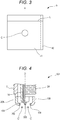
- the content proportion of each constituent in the main body portion 41 and the front surface layer 42 can be obtained as follows. First, the tip 9 is cut across the cross section including the axial line A to expose the cut cross section. As shown in Fig. 3 , the composition of the main body portion 41 is found as follows. Wavelength Dispersive X-ray Spectrometer (WDS) analysis is performed on the proximity of the center at the cut cross section with an EPMA to measure a mass composition at each measurement position.
- WDS Wavelength Dispersive X-ray Spectrometer
- a point passing through a center of a line segment from the end portion to the end portion of the cut cross section in the axial line A direction and being the center of the line segment from the end portion to the end portion of the cut cross section in the direction perpendicular to the axial line A is assumed as a center point C.
- An analysis value at a region of a spot diameter of 100 ⁇ m at this center point C is regarded as the composition of the main body portion 41.
- the composition at the measurement point can be obtained as the composition of the front surface layer 42 by analyzing the region of the spot diameter of 1 ⁇ m at the position inside 2 ⁇ m from the end portion of the cut cross section.
- the thickness of the front surface layer 42 can be obtained as follows. Elementary analysis is conducted on a line segment L, which is in the direction perpendicular to the axial line A, at intervals of 1 ⁇ m. At the measured points from the end portion to the other end of the line segment L, the length of a part where the content proportion of Ni is 8 mass% or more is the thickness. The front surface layer 42 at the thickness of 20 ⁇ m or more may be analyzed at intervals of 10 ⁇ m. The front surface layer 42 is disposed at the surface of the main body portion 41. Accordingly, the point at which the content proportion of Ni is 8 mass% or more is usually present at a constant length from one end to the other end on the line segment L. The elementary analysis on a plurality of the any given line segments L in the direction perpendicular to the axial line A allows obtaining the thickness at any given position at the side surface of the tip 9.
- the front surface layer 42 be at least disposed at a site where the intake air gas is likely to directly hit among the entire surface of the main body portion 41, or may be disposed at the entire surface of the main body portion 41.
- the site where the intake air gas is likely to directly hit is as follows.
- the site for the tip 9 to be bonded to both the center electrode 4 and the ground electrode 8 is also a side peripheral surface of the main body portion 41, namely, an outer peripheral surface of the main body portion 41 in the radial direction of the axial line A.
- the site for the tip 309 joined to the center electrode 104 is the entire surface other than the surface joined to the center electrode 104.
- the sites for the tips 109 and 209 joined to the ground electrodes 108 and 208 are the surfaces facing the distal end side of an axial line O' among the side peripheral surfaces of the main body portion.
- the front surface layer 42 may be disposed at the entire surface of the main body portion 41. However, the front surface layer 42 is preferably not disposed at the surface joined to the ground electrode 8. That is, the following is preferred.
- the resistance welding, the laser beam welding, or the laser beam welding after performing the resistance welding is performed on the surface where the main body portion 41 is exposed at the tip 9 to the ground electrode 8.
- the surface and the ground electrode 8 are bonded to form the ground electrode 8 having the tip 9.
- the intake air gas does not directly hit the surface of the tip 9 joined to the ground electrode 8; therefore, the abnormal erosion does not occur in the surface. Accordingly, even with the front surface layer 42, the effect of the present invention of the application cannot be obtained.
- the tip 9, the ground electrode 8, and a similar component melt.
- the melted particles possibly disperse and accumulate at the periphery of the bonding portion. This possibly fails to maintain the quality of the spark plug, resulting in a manufacturing failure.
- at least a part of the surface of the tip 9 bonded to the ground electrode 8 is preferably formed of the main body portion 41.
- the entire surface of the surface is especially preferable to be formed of only the main body portion 41.
- a total content proportion of Ni and the elements having lower melting point than Ni to the total mass of the region is preferable to be more than 0 mass% to 7 mass% or less.
- a region T 1 at the tip 9 is the region T 1 of the distal end portion of the column-shaped tip 9 at the thickness of 0.2 mm.
- the region T 1 has a disk-shaped body.
- the region T 1 includes the main body portion 41 and the front surface layer 42.
- the region in the range of thickness 0.2 mm from the front end surface of the tip 9 includes the fusion portion 43, which is formed when welding the tip 9 to the ground electrode 8, the region includes the main body portion 41, the front surface layer 42, and the fusion portion 43.
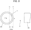
- the gaps G' are formed between side surfaces of the tip 309, which is disposed at the center electrode 104, and front end surfaces of the tips 109 and 209, which are disposed at the ground electrodes 108 and 208.
- a region T 2 in the tip 309 disposed at the center electrode 104 is the region T 2 included between a tangent F 1 and a second tangent F 2 .
- the tangent F 1 is on a point E.
- the point E is the closest from the tip 109, which is disposed at the ground electrode 108, viewed from the distal end side of the tip 309 in the axial line O' direction.
- the second tangent F 2 moves from the tangent F 1 toward the opposite side from the side that the gap G' is positioned by 0.2 mm.
- the region T 2 has an arc-cutout-pillar-shaped body.
- elements having lower melting point than Ni for example, Fe, Al, Si, Co, Cu, Au, and Ag can be listed.
- the total content proportion of the Ni and the elements having lower melting point than Ni in the regions T 1 and T 2 is within the range, this allows providing the spark plug that reduces the abnormal erosion and features excellent wear resistance.
- Ni and the elements having lower melting point than Ni are mainly contained in the front surface layer 42. Accordingly, the total content proportion of Ni and the elements having lower melting point than Ni in the regions T 1 and T 2 shows a volume occupied by the front surface layer 42 at the regions T 1 and T 2 to some extent.
- the thickness of the front surface layer 42 is only necessary to be 2 ⁇ m or more.
- the upper limit value of the thickness may be set appropriately in a range that can achieve the problem of this invention, for example, equal to or less than the diameter of the main body portion 41.
- the thicker the front surface layer 42 is the more the abnormal erosion can be reduced. Meanwhile, the thicker the front surface layer 42 is, the smaller the volume of the main body portion is, adversely deteriorating the wear resistance. Accordingly, designing the total content proportion of Ni and the elements having lower melting point than Ni in the regions T 1 and T 2 within the range can provide the spark plug that reduces the abnormal erosion and features excellent wear resistance.
- the total content proportion of Ni and the elements having lower melting point than Ni at the regions in the tip can be measured as follows. First, the tip is cut at the position of 0.2 mm from the front end surface of the tip forming the gap toward the opposite side from the side that the gap G is positioned. After dissolving the disk-shaped body at the distal end side of the cut tip, chemical analysis (ICP emission spectrometry) can measure the mass proportion of the elements.
- ICP emission spectrometry chemical analysis
- the tip 9 has a columnar shape in this embodiment.
- the shape of the tip 9 is not especially limited.
- an appropriate shape such as an elliptic cylinder shape, a prismatic shape, and a plate shape can be employed.
- the tip projects from the surface of the ground electrode by 0.15 mm or more.
- At least a part of a curvature radius R of an outline of the cut cross section obtained by cutting at the cross section perpendicular to the axial line A of the tip at any given position of the tip disposed at the ground electrode at 0.15 mm or more from the surface of the ground electrode to the direction perpendicular to the surface is 0.33 mm or more. That is, when observing the cut cross section, at the outer peripheral surface in contact with the atmosphere, the part at the curvature radius R of 0.33 mm or more is present.
- the tip 9 meeting the conditions (1) and (2) for example, a column-shaped tip at a radius of 0.33 mm or more and a height of 0.15 mm or more can be listed. Not only in the case where the tip 9 is disposed at the ground electrode 8 but also in the case where the tip 9 is disposed at the center electrode, the tip meeting both conditions (1) and (2) can further obtain the effect. When the tip projects from the surface of the ground electrode by 0.6mm or more, the abnormal erosion is further likely to occur, allowing obtaining the effect of this invention.
- the tip may include a diffusion layer between the main body portion and the front surface layer as a modification. Performing heat treatment on the tip with the front surface layer at the surface of the main body portion mutually diffuses the elements between the main body portion and the front surface layer.
- the diffusion layer is a layer thus formed. Accordingly, the diffusion layer has a gradient structure where the composition gradually changes from the composition of the main body portion to the composition of a front surface portion of the front surface layer.
- the tip with such gradient structure provides good adhesion property between the main body portion and the front surface layer. This is less likely to peel the front surface layer from the main body portion, providing an effect of reducing the abnormal erosion brought by the front surface layer over a long period of time.
- the thickness of the diffusion layer is preferably at least 2 ⁇ m or more.
- too thick diffusion layer promotes alloying the main body portion and the front surface layer. This declines coefficient of thermal conductivity, and the spark erosion is likely to occur. Therefore, the thickness of the diffusion layer is preferable to be less than 200 ⁇ m.
- the thickness of the diffusion layer is within the range, this provides good adhesion property between the main body portion and the front surface layer while ensuring the spark erosion resistance, causing the front surface layer to be less likely to peel off from the main body portion.
- the thickness of the diffusion layer can be obtained similar to the case of obtaining the thickness of the front surface layer. That is, as shown in Fig.
- the elementary analysis is conducted on the any given line segment L, which is in the direction perpendicular to the axial line A at the cut cross section of the tip.
- the length on the line segment L in the region where the content proportion of Ni gradually fluctuates can be obtained as the thickness of the diffusion layer.
- the content proportion of Ni gradually fluctuates, however, in most cases, the content proportion of Ni decreases from the front surface layer of large content proportion of Ni to the main body portion of small content proportion of Ni.
- the content proportion of Ni possibly increases from the surface to the center of the tip. Even in this case, as long as the content proportion is within the range of this invention, the effect of reducing the abnormal erosion can be obtained.
- the spark plug 1 is, for example, manufactured as follows. First, for the tip 9, a core material, which becomes the main body portion 41, is manufactured. Forming the front surface layer 42 at the surface of this core material manufactures the spark plug 1.
- the core material which becomes the main body portion 41
- metal constituents are combined such that the content proportion of each constituent becomes within the above-described range, thus raw material powder is prepared.
- Arc melting is performed on this raw material powder to form an ingot.
- This ingot is hot forged to form a rod material.
- this rod material is groove-rolled by several times, and if necessary, swaging is performed.
- the round rod material with a circular cross section is formed.
- This round rod material is cut to a predetermined length.
- the front surface layer is formed at the surface of this round rod material.
- the round rod material with this front surface layer formed is cut to the desired length as the tip 9.
- the tip 9 with the front surface layer 42 at the surface of the main body portion 41 is manufactured.
- the shape of the core material which will be the main body portion 41, is not limited to the columnar shape.
- the wire drawing treatment is performed on the ingot with a quadrangular die to process the ingot into a square log.
- the square log is cut to the predetermined length so as to form the square log into, for example, a square bar shape.
- the method for forming the front surface layer 42 at the surface of the core material is not specifically limited.
- an electrolytic plating process, an electroless plating process, a chemical vapor deposition method, a physical vapor deposition method, bonding a material of different kind (a clad metal material) where a cylindrical rod material is pasted on the core material and processed, or a similar method can be listed.
- the electrolytic plating process or the electroless plating process forms the front surface layer 42 at the surface of the core material
- a composition, a current value, and a voltage value of a plating bath, a heat treatment condition, or a similar condition is regulated, and the plating process is performed.
- Platings with different compositions may be consecutively formed at the surface of the core material to be a multilayer structure.
- CVD chemical vapor deposition method
- MOCVD MOCVD
- PECVD PECVD
- LPCVD normal pressure CVD
- CCVD or a similar method
- PVD physical vapor deposition method
- various sputtering methods such as a DC sputtering and a high frequency sputtering
- various ion plating methods such as a high-frequency ion plating, a molecular beam epitaxy method, a laser ablation method, an ionized cluster beam deposition method, an ion beam deposition method, or a similar method
- various sputtering methods such as a DC sputtering and a high frequency sputtering
- various ion plating methods such as a high-frequency ion plating
- a molecular beam epitaxy method such as a laser ablation method, an ionized cluster beam deposition method, an ion beam deposition method, or a similar method
- the following can be listed.
- One method is to form the front surface layer 42 at the entire surface of the core material, and then to cut the core material with the front surface layer 42 vertical to the axial line of this core material.
- Another method is to form the front surface layer 42 at the entire surface of the core material and to, for example, partially cut and chop off the front surface layer 42 for removal.
- the tip where the main body portion is exposed at any site of the tip is manufactured.
- the tip 9 in this invention may perform a heat treatment manufacturing process in addition to the manufacturing process to form the diffusion layer, which is formed by mutual diffusion of the elements in the main body portion 41 and the front surface layer 42.
- the heat treatment manufacturing process is performed as follows. After forming the front surface layer 42 at the surface of the core material, for example, the front surface layer 42 is maintained at a temperature of 600 to 1300°C for 0 to 10 hours. Maintaining for 0 hours means a temperature fall immediately after a temperature rise.
- the heating method is not especially limited. The heating may be performed by an atmospheric control with an electric furnace, or the heating may be performed with a burner.
- the heat treatment manufacturing process may be performed by several times.
- the tip may be manufactured by the method similar to the tip 9 to be bonded to the ground electrode 8.
- the tip may be manufactured by the conventionally-known method.
- the center electrode 4 and the ground electrode 8 for example, using a vacuum melting furnace, a hot metal alloy with a desired composition is prepared. The wire drawing treatment or a similar treatment is performed on this hot metal to appropriately adjust the hot metal to the predetermined shape and predetermined dimensions.
- the center electrode 4 and the ground electrode 8 can be fabricated. Assume the case where the center electrode 4 is formed of the outer layer and the core portion, which is disposed so as to be embedded into the axial center portion of this outer layer.
- an inner material made of the Cu alloy, which exhibits higher coefficient of thermal conductivity than an outer material, or a similar material is inserted into the outer material made of the Ni alloy or a similar material formed into a cup.
- the center electrode 4 with the core portion at the inside of the outer layer is formed.
- the ground electrode 8 also may be formed of the outer layer and the core portion similar to the center electrode 4.
- the inner material is inserted into the outer material formed into the cup, and the plastic work such as the extrusion process is performed. Then, the member on which the plastic work is performed to have an approximately prismatic shape can be the ground electrode 8.
- the one end portion of the ground electrode 8 is bonded by electrical resistance welding, laser beam welding, or a similar welding.
- Zn plating or Ni plating is performed on the metal shell 7 to which the ground electrode 8 is bonded.
- trivalent chromate treatment may be performed. The plating performed on the ground electrode may be peeled.
- the tip 9 fabricated as described above is melted and fixed to the ground electrode 8 by, for example, the resistance welding and/or the laser beam welding.
- the tip 9 is installed at the predetermined position of the ground electrode 8 and the resistance welding is performed while pressing the tip 9.
- the tip 9 is installed at the predetermined position of the ground electrode 8.
- laser beam is irradiated on a contact portion of the tip 9 and the ground electrode 8 from a direction parallel to the contact surface of the tip 9 and the ground electrode 8 partially or across the whole circumference. After performing the resistance welding, the laser beam welding may be performed.
- the tip 9 and the ground electrode 8 melt, possibly resulting in dispersion and accumulation of the melted particles to the periphery of the bonding portion. This fails to maintain the quality of the spark plug, possibly resulting in a manufacturing failure.
- the front surface layer 42 is not disposed at the surface of the tip 9 to be bonded to the ground electrode 9 and the main body portion 41 is exposed at the tip 9, when bonding the tip 9 to the ground electrode 8, this allows preventing the melted particles from the tip 9 and the ground electrode 8 from dispersing. This also allows reducing a count of the spark plug resulting in manufacturing failure.
- the tip 9 is preferable whose main body portion is exposed at the surface of the tip 9 to be bonded to the ground electrode 8.
- the tip can be bonded by the method similar to bonding the tip 9 to the ground electrode 8.
- the insulator 3 is fabricated by sintering ceramic or a similar material into a predetermined shape.
- the center electrode 4 is disposed to be inserted into the axial hole 2 of this insulator 3.
- the composition forming the first seal body 22, the composition forming the resistor 21, and the composition forming the second seal body 23 are pre-compressed into the axial hole 2 in this order for filling the axial hole 2.
- the compositions are compressed and heated.
- the compositions are sintered, forming the resistor 21, the first seal body 22, and the second seal body 23.
- the insulator 3 to which this center electrode 4 or a similar member is secured is assembled. Finally, the distal end portion of the ground electrode 8 is bent toward the center electrode 4 side such that the one end of the ground electrode 8 is opposed to the distal end portion of the center electrode 4, thus manufacturing the spark plug 1.
- the spark plug 1 according to the present invention is used as an ignition plug for the internal combustion engine for vehicles, for example, a gasoline engine.
- the spark plug 1 has a screw hole at a head (not shown), which defines and forms the combustion chamber of the internal combustion engine.
- the screw portion 24 is screwed with the screw hole to secure the spark plug 1 to the predetermined position.
- the spark plug 1 according to this invention is also applicable to any internal combustion engine. Even if the spark plug 1 according to the present invention is used in the combustion chamber at a high temperature and high oxygen concentration, the tip is placed under conditions where the intake air gas is likely to directly hit the surface of the tip, and oxygen concentration and the temperature at the periphery of the tip widely change, the spark plug 1 can reduce the abnormal erosion at the side surface of the tip. Accordingly, the spark plug 1 is, for example, particularly suitable for the internal combustion engine such as a direct-injection gasoline engine operated in the lean burn state.
- the spark plug 1 is not limited to the above-described embodiments, and various modifications can be performed within the range which can achieve the object of the invention.
- the front end surface of the center electrode 4 and the front end surface of the tip 9, which is disposed at the ground electrode 8 are opposed via the gap G in the axial line O direction.
- the side surfaces of the tip 309, which is disposed at the center electrode 104, and the front end surfaces of the tips 109 and 209, which are disposed at the ground electrodes 108 and 208 may be disposed to be opposed via the gap G' in the radial direction of the center electrode.
- the ground electrodes, which are opposed to the side surfaces of the tip 309 disposed at the center electrode may be disposed by a single or plural.
- the tip with front surface layer which has the front surface layer, was manufactured as follows. A core material, which became the main body portion, was manufactured. Then, by the electrolytic plating process or bonding the material of different kind (the clad metal), the front surface layer was formed at the surface of this core material.
- the core material was obtained as follows. Raw material powders with a predetermined composition were combined, and arc melting was performed on the powder to form an ingot. Hot forging, hot rolling, and hot swaging were performed on this ingot. Furthermore, the wire drawing treatment was performed to form a round rod material at the diameter of 0.35 mm and a predetermined length. At the side peripheral surface of this round rod material, the electrolytic plating process formed a front surface layer with the predetermined composition. Thereafter, the round rod material was cut to a predetermined length, thus obtaining the tip with front surface layer.
- the tip with front surface layer includes the column-shaped main body portion at the diameter of 0.35 mm and the height of 0.6 mm.
- the tip with front surface layer includes the front surface layer at the side peripheral surface of the main body portion.
- the core material was obtained as follows. Raw material powders with a predetermined composition were combined, and arc melting was performed on the powder to form an ingot. Hot forging, hot rolling, and hot swaging were performed on this ingot. Furthermore, the wire drawing treatment was performed to form a round rod material at a predetermined length. To the side peripheral surface of this round rod material, a cylindrical material equivalent to the front surface layer with the predetermined composition was bonded, and the wire drawing treatment was performed. Thereafter, the round rod material was cut to a predetermined length, thus obtaining the tip with front surface layer.
- the tip with front surface layer includes the column-shaped main body portion at the diameter of 0.35 mm and the height of 0.6 mm.
- the tip with front surface layer includes the front surface layer at the side peripheral surface of the main body portion.
- the front surface layer was formed at the surface of the main body portion by any of the methods as well, when performing the heat treatment on the tip as necessary after forming the front surface layer, the elements diffused between the main body portion and the front surface layer, thus forming the diffusion layer. Accordingly, the diameter of the main body portion became less than 0.35 mm.
- the tip without front surface layer was formed as follows similar to the core material for the tip with front surface layer.
- the round rod material at the diameter of 0.35 mm was formed. This round rod material was cut to a predetermined length, thus forming the column-shaped tip without front surface layer at the diameter of 0.35 mm and the height of 0.6 mm.
- the heat treatment manufacturing process was performed on a part of the obtained tip with front surface layer.
- the heat treatment manufacturing process maintained the tip with front surface layer at a predetermined temperature within a range of 600 to 1300°C in the electric furnace for predetermined hours within a range of 0 to 10 hours.
- the diffusion layer was formed between the main body portion and the front surface layer.
- the resistance welding was performed on the obtained tip without front surface layer and the tip with front surface layer (may be referred to as the tip) to a ground electrode formed of an inconel 601. Then, the tip and the ground electrode were bonded by the laser beam welding. Thus, the spark plug specimen with the structure shown in Fig. 1 was manufactured.
- the diameter of the main body portion was changed to 0.7 mm, and the thickness of the front surface layer and the compositions of the main body portion and the front surface layer were changed. Otherwise, the spark plug specimens were manufactured similar to the test numbers 1 to 59.
- the main body portion contains Pt as the main constituent and Rh of 10%.
- the elements other than Ni in the front surface layer were fabricated so as to be only the elements contained in the main body portion.
- the radius of the tips was changed. Otherwise, the spark plug specimens were manufactured similar to the test numbers 9 and 19. Together with this, for "Evaluation for Abnormal Erosion", which will be described later, as a sample used for measuring an abnormal erosion start time t 1 at the use of the tip without front surface layer, the spark plug specimens with the tip without front surface layer having the radius identical as the test numbers 82 to 90 were fabricated.
- Mass compositions of the compositions of the tips were measured by WDS analysis with an EPMA (JXA-8500F manufactured by JEOL Ltd.).
- the tip was cut off at the plane including the axial line A of the tip.
- the mass composition near the center of this cut cross section was measured (acceleration voltage: 20kV, spot diameter: 100 ⁇ m).
- the spot diameter was set to 1 ⁇ m.
- the mass composition was measured on the any given two line segments L, which are in the direction perpendicular to the axial line A at the cut cross section at intervals of 1 ⁇ m.
- the mass composition was measured from the end portion toward the other end of the two line segments L. Then, the length of the part where the content proportion of Ni becomes 8 mass% or more was obtained. Arithmetic mean values of these values are shown as the thickness of the front surface layer in Table 1. If the surface Ni content proportion was less than 8 mass%, as the thickness of the front surface layer, the mass composition was measured from the end portion toward the other end of the line segment L. Then, the length of the part where the content proportion of Ni became 80% of the surface Ni content proportion was regarded as the thickness of the front surface layer. The mass composition was measured from the end portion toward the other end of the line segment L. When the part where the content proportion of Ni gradually fluctuates is 2 ⁇ m or more, it is determined that the diffusion layer was present.
- the tip was cut at the position of 0.2 mm from the surface of the tip forming the gap G to the opposite side from the side that the gap G is positioned. Disk-shaped bodies at the distal end side of the tips were dissolved by a required quantity. After that, the chemical analysis (ICP emission spectrometry) measured the mass proportion of Ni and the elements having lower melting point than Ni. The measurement results are shown in Table 3.
- the manufactured spark plug specimen was mounted to an engine with supercharger for testing (initial spark discharge voltage: 20 kV or more, a displacement: 660 cc, and three cylinders).
- the ground electrode was adjusted to a position of not disturbing a flow of the intake air gas such that the intake air gas was likely to directly hit the tip disposed at the ground electrode.
- the durability test was conducted at an Air/Fuel ratio (air/fuel) of 11.3, at full throttle with a state of an engine revolution of 6000 rpm maintained, and the engine was operated for 100 hours.
- a measured temperature at a position of 1 mm from a distal end of a ground electrode base material with a thermocouple was 950°C.
- An abnormal erosion start time t 1 is time when using the tip without front surface layer.
- An abnormal erosion start time t 2 is time when using the tip with front surface layer that has the front surface layer at the surface of the main body portion with the identical composition as the tip without front surface layer.
- a ratio of the abnormal erosion start time t 2 to the abnormal erosion start time t 1 (t 2 /t 1 ) was calculated.
- the abnormal erosion was evaluated in accordance with the following criteria. The results are shown in Tables 1 and 2.
- the length of the gap G was measured before and after the durability test. An increased amount of the gap G before and after the durability test was calculated. An increased proportion of gap of an amount of increased gap H 2 when using the tip with front surface layer with respect to an amount of increased gap H 1 when using the tip without front surface layer: ⁇ (H 2 - H 1 )/H 1 ⁇ ⁇ 100 was calculated. The wear resistance was evaluated in accordance with the following criteria. The results are shown in Table 3.
- the radius of the column-shaped tip was changed. Otherwise, the evaluation was conducted similar to the "Evaluation for Abnormal Erosion" using the spark plug specimen with the tip similar to the test numbers 9 and 19.
- the start time of abnormal erosion t 2 of the tips with front surface layer of test numbers 82 to 90 as shown in Table 5 and the start time of abnormal erosion t 1 of the tips without front surface layer with the identical radius were measured, and the ratio (t 2 /t 1 ) was calculated. The abnormal erosion was evaluated from the calculated values.
- the abnormal erosion did not occur in the tips of test numbers 1 to 6 with the composition outside the range of the composition of the main body portion in the present invention. Accordingly, it was found that the abnormal erosion occurred at the tip with a specific composition. As shown in Table 1, compared with the tip without front surface layer, which did not have the front surface layer, the tip with front surface layer that had the front surface layer containing Ni of 8 mass% or more and at the thickness of 2 ⁇ m or more reduced the abnormal erosion. On the other hand, the tip with front surface layer that had the front surface layer not meeting any one of the conditions of the content proportion of Ni being 8 mass% or more and the thickness of 2 ⁇ m or more did not reduce the abnormal erosion.
- the tips of test numbers 14, 29, 30, 52, 53, and 54 generated fine cracks at a boundary part between the main body portion and the front surface layer.
- the tips of the test numbers 34, 55, 56, and 57 generated further larger cracks at the boundary part between the main body portion and the front surface layer.
- the tip of the test number 58 generated larger cracks at the boundary part between the main body portion 41 and the front surface layer 42.
- the tip of the test number 20 with the front surface layer containing Ni of 100% reduced the abnormal erosion.
- the tip of the test number 59 with the front surface layer containing Ag of 100% did not reduce the abnormal erosion. This found that disposing the front surface layer containing Ni allows reducing the abnormal erosion.
- the tip of the test number 10 where the front surface layer was disposed at only the side peripheral surface of the main body portion exhibited low spatter ratio. Accordingly, the tip with the front surface layer at only the side peripheral surface of the main body portion can reduce the manufacturing failure during manufacturing of the spark plug.
Landscapes
- Chemical & Material Sciences (AREA)
- Engineering & Computer Science (AREA)
- Materials Engineering (AREA)
- Mechanical Engineering (AREA)
- Metallurgy (AREA)
- Organic Chemistry (AREA)
- Spark Plugs (AREA)
- Ignition Installations For Internal Combustion Engines (AREA)
Claims (5)
- Bougie d'allumage (1, 101) comprenant :une électrode centrale (4, 104) ; etune électrode de masse (8, 108) disposée créant un espace (G, G') avec l'électrode centrale (4, 104), dans laquelleau moins l'une de l'électrode centrale (4, 104) et de l'électrode de masse (8, 108) comprend une pointe (9, 109, 209, 309) formant l'espace (G, G'),la pointe (9, 109, 209, 309) comprenant une partie de corps principal (41) et une couche de surface latérale périphérique externe (42), une composition de la partie de corps principal (41) étant du Pt en tant que constituant principal et du Ni de 0 % en masse ou plus à moins de 8 % en masse, la couche de surface latérale périphérique externe (42) étant disposée au moins sur une surface radialement à l'extérieur d'une ligne axiale (A) s'étendant dans une direction allant du centre de la partie de corps principal (41) à l'espace (G, G'), la couche de surface latérale périphérique externe (42) contenant du Ni de 8 % en masse ou plus et ayant une épaisseur de 2 µm ou plus ; caractérisé en ce que :la composition de la partie de corps principal (41) étant également Rh de 5 % en masse ou plus ; etdans une région (T1, T2) ayant une épaisseur de 0,2 mm à partir d'une surface de la pointe (9, 109, 209, 309) formant l'espace (G, G') à un côté opposé à un côté sur lequel l'espace (G, G') est positionné, une proportion de teneur totale en Ni et un élément ayant un point de fusion inférieur à celui du Ni pour une masse totale de la région (T1, T2) est de 7 % en masse ou moins.
- Bougie d'allumage (1, 101) selon la revendication 1, dans laquelle une composition de la partie de corps principal (41) est le Ni de 0 % en masse ou plus à 1 % en masse ou moins.
- Bougie d'allumage (1, 101) selon la revendication 1 ou 2, dans laquelle la couche de surface latérale périphérique externe (42) contient du Ni de 40 % en masse ou plus et a une épaisseur de 2 µm ou plus.
- Bougie d'allumage (1, 101) selon l'une quelconque des revendications 1 à 3, dans laquelle
l'électrode centrale (4, 104) comprenant la pointe (9, 109, 209, 309) ou l'électrode de masse (8, 108) comprenant la pointe (9, 109, 209, 309) est formée en collant une surface où la partie de corps principal (41) est exposée au niveau de la pointe (9, 109, 209, 309) à l'électrode centrale (4, 104) ou l'électrode de masse (8, 108). - Bougie d'allumage (1, 101) selon l'une quelconque des revendications 1 à 4, dans laquelle
lorsque la pointe (9, 109, 209, 309) fait saillie à partir de l'électrode de masse (8, 108) de 0,15 mm ou plus, à toute position donnée de la pointe (9, 109, 209, 309) faisant saillie de 0,15 mm ou plus, la surface latérale périphérique extérieure en contact avec une atmosphère a une partie avec un rayon de courbure (R) de 0,33 mm ou plus.
Applications Claiming Priority (2)
| Application Number | Priority Date | Filing Date | Title |
|---|---|---|---|
| JP2013239616A JP5815649B2 (ja) | 2013-11-20 | 2013-11-20 | スパークプラグ |
| PCT/JP2014/004649 WO2015075855A1 (fr) | 2013-11-20 | 2014-09-10 | Bougie d'allumage |
Publications (3)
| Publication Number | Publication Date |
|---|---|
| EP3073591A1 EP3073591A1 (fr) | 2016-09-28 |
| EP3073591A4 EP3073591A4 (fr) | 2017-10-18 |
| EP3073591B1 true EP3073591B1 (fr) | 2020-08-05 |
Family
ID=53179153
Family Applications (1)
| Application Number | Title | Priority Date | Filing Date |
|---|---|---|---|
| EP14863887.7A Active EP3073591B1 (fr) | 2013-11-20 | 2014-09-10 | Bougie d'allumage |
Country Status (6)
| Country | Link |
|---|---|
| US (1) | US9948068B2 (fr) |
| EP (1) | EP3073591B1 (fr) |
| JP (1) | JP5815649B2 (fr) |
| KR (1) | KR101875295B1 (fr) |
| CN (1) | CN105745798B (fr) |
| WO (1) | WO2015075855A1 (fr) |
Families Citing this family (3)
| Publication number | Priority date | Publication date | Assignee | Title |
|---|---|---|---|---|
| JP6604869B2 (ja) * | 2016-02-19 | 2019-11-13 | 石福金属興業株式会社 | 白金パラジウムロジウム合金 |
| JP6637452B2 (ja) * | 2017-01-25 | 2020-01-29 | 日本特殊陶業株式会社 | スパークプラグ |
| JP6745319B2 (ja) * | 2018-11-09 | 2020-08-26 | 日本特殊陶業株式会社 | スパークプラグ |
Citations (1)
| Publication number | Priority date | Publication date | Assignee | Title |
|---|---|---|---|---|
| US20070222350A1 (en) * | 2006-03-24 | 2007-09-27 | Federal-Mogul World Wide, Inc. | Spark plug |
Family Cites Families (23)
| Publication number | Priority date | Publication date | Assignee | Title |
|---|---|---|---|---|
| JPS60130081A (ja) | 1983-12-15 | 1985-07-11 | 日本特殊陶業株式会社 | スパ−クプラグ |
| JP2805322B2 (ja) | 1989-03-02 | 1998-09-30 | 日本特殊陶業株式会社 | 内燃機関用スパークプラグ |
| JPH03101086A (ja) | 1989-09-14 | 1991-04-25 | Ngk Spark Plug Co Ltd | 内燃機関用スパークプラグ |
| DE3941649A1 (de) * | 1989-12-16 | 1991-06-20 | Bosch Gmbh Robert | Verfahren zur herstellung von elektroden fuer zuendkerzen sowie zuendkerzen-elektroden |
| JP2847681B2 (ja) * | 1991-12-03 | 1999-01-20 | 日本特殊陶業株式会社 | スパークプラグの中心電極の製造方法 |
| DE69311173T2 (de) * | 1992-03-19 | 1997-12-04 | Philips Electronics Nv | Zeilenausgangstransformator |
| JPH05343156A (ja) | 1992-06-11 | 1993-12-24 | Tanaka Kikinzoku Kogyo Kk | 白金被覆イリジウム材料 |
| JP2853108B2 (ja) * | 1992-06-17 | 1999-02-03 | 日本特殊陶業 株式会社 | スパークプラグ |
| US6528929B1 (en) * | 1998-11-11 | 2003-03-04 | Ngk Spark Plug Co., Ltd. | Spark plug with iridium-based alloy chip |
| JP4291540B2 (ja) | 2001-03-28 | 2009-07-08 | 日本特殊陶業株式会社 | スパークプラグ |
| JP2004031300A (ja) | 2002-05-10 | 2004-01-29 | Ngk Spark Plug Co Ltd | スパークプラグ |
| JP4368100B2 (ja) | 2002-10-01 | 2009-11-18 | 日本特殊陶業株式会社 | スパークプラグ |
| JP3902756B2 (ja) | 2002-10-31 | 2007-04-11 | 日本特殊陶業株式会社 | スパークプラグ |
| EP1677400B1 (fr) | 2004-12-28 | 2019-01-23 | Ngk Spark Plug Co., Ltd | Bougie d'allumage |
| JP4944433B2 (ja) | 2004-12-28 | 2012-05-30 | 日本特殊陶業株式会社 | スパークプラグ |
| JP4616033B2 (ja) | 2005-02-21 | 2011-01-19 | 株式会社フルヤ金属 | スパークプラグ用電極チップ |
| US7569979B2 (en) | 2006-04-07 | 2009-08-04 | Federal-Mogul World Wide, Inc. | Spark plug having spark portion provided with a base material and a protective material |
| EP2234226B1 (fr) | 2008-01-10 | 2018-03-28 | NGK Spark Plug Co., Ltd. | Bougie d'allumage pour moteur à combustion interne et son procédé de fabrication |
| JP5226838B2 (ja) * | 2011-08-04 | 2013-07-03 | 日本特殊陶業株式会社 | スパークプラグ |
| JP5249393B2 (ja) | 2011-09-13 | 2013-07-31 | 田中貴金属工業株式会社 | スパークプラグ用の貴金属合金チップ及びその製造方法 |
| WO2013063092A1 (fr) * | 2011-10-24 | 2013-05-02 | Federal-Mogul Ignition Company | Electrode de bougie d'allumage et procédé de fabrication de bougie d'allumage |
| US9028289B2 (en) * | 2011-12-13 | 2015-05-12 | Federal-Mogul Ignition Company | Electron beam welded electrode for industrial spark plugs |
| CN103138161B (zh) | 2012-11-01 | 2017-03-01 | 昆明富尔诺林科技发展有限公司 | 用于火花塞的贵金属合金复合材料电极及其制造方法 |
-
2013
- 2013-11-20 JP JP2013239616A patent/JP5815649B2/ja active Active
-
2014
- 2014-09-10 EP EP14863887.7A patent/EP3073591B1/fr active Active
- 2014-09-10 US US15/036,572 patent/US9948068B2/en active Active
- 2014-09-10 KR KR1020167012654A patent/KR101875295B1/ko active IP Right Grant
- 2014-09-10 WO PCT/JP2014/004649 patent/WO2015075855A1/fr active Application Filing
- 2014-09-10 CN CN201480063619.5A patent/CN105745798B/zh active Active
Patent Citations (1)
| Publication number | Priority date | Publication date | Assignee | Title |
|---|---|---|---|---|
| US20070222350A1 (en) * | 2006-03-24 | 2007-09-27 | Federal-Mogul World Wide, Inc. | Spark plug |
Also Published As
| Publication number | Publication date |
|---|---|
| US9948068B2 (en) | 2018-04-17 |
| US20160294164A1 (en) | 2016-10-06 |
| KR101875295B1 (ko) | 2018-07-05 |
| CN105745798B (zh) | 2017-09-26 |
| JP2015099721A (ja) | 2015-05-28 |
| WO2015075855A1 (fr) | 2015-05-28 |
| CN105745798A (zh) | 2016-07-06 |
| EP3073591A1 (fr) | 2016-09-28 |
| JP5815649B2 (ja) | 2015-11-17 |
| KR20160071447A (ko) | 2016-06-21 |
| EP3073591A4 (fr) | 2017-10-18 |
Similar Documents
| Publication | Publication Date | Title |
|---|---|---|
| EP3306762B1 (fr) | Bougie d'allumage | |
| EP2234226B1 (fr) | Bougie d'allumage pour moteur à combustion interne et son procédé de fabrication | |
| KR101513325B1 (ko) | 내연 엔진용 스파크 플러그 | |
| EP3355423B1 (fr) | Bougie d'allumage | |
| US10312669B2 (en) | Spark plug | |
| EP2738892B1 (fr) | Bougie d'allumage | |
| EP3073591B1 (fr) | Bougie d'allumage | |
| EP3193415B1 (fr) | Bougie d'allumage | |
| EP2579401B1 (fr) | Bougie d'allumage | |
| JP6061307B2 (ja) | スパークプラグ | |
| WO2021161845A1 (fr) | Pastille de métal précieux pour bougie d'allumage, électrode pour bougie d'allumage et bougie d'allumage | |
| EP3068000B1 (fr) | Bougie d'allumage |
Legal Events
| Date | Code | Title | Description |
|---|---|---|---|
| PUAI | Public reference made under article 153(3) epc to a published international application that has entered the european phase |
Free format text: ORIGINAL CODE: 0009012 |
|
| 17P | Request for examination filed |
Effective date: 20160413 |
|
| AK | Designated contracting states |
Kind code of ref document: A1 Designated state(s): AL AT BE BG CH CY CZ DE DK EE ES FI FR GB GR HR HU IE IS IT LI LT LU LV MC MK MT NL NO PL PT RO RS SE SI SK SM TR |
|
| AX | Request for extension of the european patent |
Extension state: BA ME |
|
| DAX | Request for extension of the european patent (deleted) | ||
| A4 | Supplementary search report drawn up and despatched |
Effective date: 20170915 |
|
| RIC1 | Information provided on ipc code assigned before grant |
Ipc: F02P 13/00 20060101ALI20170911BHEP Ipc: C22C 5/04 20060101ALI20170911BHEP Ipc: C22C 19/03 20060101ALI20170911BHEP Ipc: H01T 13/39 20060101AFI20170911BHEP |
|
| STAA | Information on the status of an ep patent application or granted ep patent |
Free format text: STATUS: EXAMINATION IS IN PROGRESS |
|
| 17Q | First examination report despatched |
Effective date: 20190529 |
|
| GRAP | Despatch of communication of intention to grant a patent |
Free format text: ORIGINAL CODE: EPIDOSNIGR1 |
|
| STAA | Information on the status of an ep patent application or granted ep patent |
Free format text: STATUS: GRANT OF PATENT IS INTENDED |
|
| INTG | Intention to grant announced |
Effective date: 20200511 |
|
| RAP1 | Party data changed (applicant data changed or rights of an application transferred) |
Owner name: NGK SPARK PLUG CO., LTD. |
|
| GRAS | Grant fee paid |
Free format text: ORIGINAL CODE: EPIDOSNIGR3 |
|
| GRAA | (expected) grant |
Free format text: ORIGINAL CODE: 0009210 |
|
| STAA | Information on the status of an ep patent application or granted ep patent |
Free format text: STATUS: THE PATENT HAS BEEN GRANTED |
|
| AK | Designated contracting states |
Kind code of ref document: B1 Designated state(s): AL AT BE BG CH CY CZ DE DK EE ES FI FR GB GR HR HU IE IS IT LI LT LU LV MC MK MT NL NO PL PT RO RS SE SI SK SM TR |
|
| REG | Reference to a national code |
Ref country code: GB Ref legal event code: FG4D |
|
| REG | Reference to a national code |
Ref country code: CH Ref legal event code: EP |
|
| REG | Reference to a national code |
Ref country code: AT Ref legal event code: REF Ref document number: 1300055 Country of ref document: AT Kind code of ref document: T Effective date: 20200815 |
|
| REG | Reference to a national code |
Ref country code: DE Ref legal event code: R096 Ref document number: 602014068729 Country of ref document: DE |
|
| REG | Reference to a national code |
Ref country code: IE Ref legal event code: FG4D |
|
| REG | Reference to a national code |
Ref country code: LT Ref legal event code: MG4D |
|
| REG | Reference to a national code |
Ref country code: NL Ref legal event code: MP Effective date: 20200805 |
|
| REG | Reference to a national code |
Ref country code: AT Ref legal event code: MK05 Ref document number: 1300055 Country of ref document: AT Kind code of ref document: T Effective date: 20200805 |
|
| PG25 | Lapsed in a contracting state [announced via postgrant information from national office to epo] |
Ref country code: FI Free format text: LAPSE BECAUSE OF FAILURE TO SUBMIT A TRANSLATION OF THE DESCRIPTION OR TO PAY THE FEE WITHIN THE PRESCRIBED TIME-LIMIT Effective date: 20200805 Ref country code: AT Free format text: LAPSE BECAUSE OF FAILURE TO SUBMIT A TRANSLATION OF THE DESCRIPTION OR TO PAY THE FEE WITHIN THE PRESCRIBED TIME-LIMIT Effective date: 20200805 Ref country code: GR Free format text: LAPSE BECAUSE OF FAILURE TO SUBMIT A TRANSLATION OF THE DESCRIPTION OR TO PAY THE FEE WITHIN THE PRESCRIBED TIME-LIMIT Effective date: 20201106 Ref country code: NO Free format text: LAPSE BECAUSE OF FAILURE TO SUBMIT A TRANSLATION OF THE DESCRIPTION OR TO PAY THE FEE WITHIN THE PRESCRIBED TIME-LIMIT Effective date: 20201105 Ref country code: ES Free format text: LAPSE BECAUSE OF FAILURE TO SUBMIT A TRANSLATION OF THE DESCRIPTION OR TO PAY THE FEE WITHIN THE PRESCRIBED TIME-LIMIT Effective date: 20200805 Ref country code: BG Free format text: LAPSE BECAUSE OF FAILURE TO SUBMIT A TRANSLATION OF THE DESCRIPTION OR TO PAY THE FEE WITHIN THE PRESCRIBED TIME-LIMIT Effective date: 20201105 Ref country code: SE Free format text: LAPSE BECAUSE OF FAILURE TO SUBMIT A TRANSLATION OF THE DESCRIPTION OR TO PAY THE FEE WITHIN THE PRESCRIBED TIME-LIMIT Effective date: 20200805 Ref country code: LT Free format text: LAPSE BECAUSE OF FAILURE TO SUBMIT A TRANSLATION OF THE DESCRIPTION OR TO PAY THE FEE WITHIN THE PRESCRIBED TIME-LIMIT Effective date: 20200805 Ref country code: HR Free format text: LAPSE BECAUSE OF FAILURE TO SUBMIT A TRANSLATION OF THE DESCRIPTION OR TO PAY THE FEE WITHIN THE PRESCRIBED TIME-LIMIT Effective date: 20200805 Ref country code: PT Free format text: LAPSE BECAUSE OF FAILURE TO SUBMIT A TRANSLATION OF THE DESCRIPTION OR TO PAY THE FEE WITHIN THE PRESCRIBED TIME-LIMIT Effective date: 20201207 |
|
| PG25 | Lapsed in a contracting state [announced via postgrant information from national office to epo] |
Ref country code: LV Free format text: LAPSE BECAUSE OF FAILURE TO SUBMIT A TRANSLATION OF THE DESCRIPTION OR TO PAY THE FEE WITHIN THE PRESCRIBED TIME-LIMIT Effective date: 20200805 Ref country code: PL Free format text: LAPSE BECAUSE OF FAILURE TO SUBMIT A TRANSLATION OF THE DESCRIPTION OR TO PAY THE FEE WITHIN THE PRESCRIBED TIME-LIMIT Effective date: 20200805 Ref country code: NL Free format text: LAPSE BECAUSE OF FAILURE TO SUBMIT A TRANSLATION OF THE DESCRIPTION OR TO PAY THE FEE WITHIN THE PRESCRIBED TIME-LIMIT Effective date: 20200805 Ref country code: RS Free format text: LAPSE BECAUSE OF FAILURE TO SUBMIT A TRANSLATION OF THE DESCRIPTION OR TO PAY THE FEE WITHIN THE PRESCRIBED TIME-LIMIT Effective date: 20200805 Ref country code: IS Free format text: LAPSE BECAUSE OF FAILURE TO SUBMIT A TRANSLATION OF THE DESCRIPTION OR TO PAY THE FEE WITHIN THE PRESCRIBED TIME-LIMIT Effective date: 20201205 |
|
| PG25 | Lapsed in a contracting state [announced via postgrant information from national office to epo] |
Ref country code: SM Free format text: LAPSE BECAUSE OF FAILURE TO SUBMIT A TRANSLATION OF THE DESCRIPTION OR TO PAY THE FEE WITHIN THE PRESCRIBED TIME-LIMIT Effective date: 20200805 Ref country code: RO Free format text: LAPSE BECAUSE OF FAILURE TO SUBMIT A TRANSLATION OF THE DESCRIPTION OR TO PAY THE FEE WITHIN THE PRESCRIBED TIME-LIMIT Effective date: 20200805 Ref country code: EE Free format text: LAPSE BECAUSE OF FAILURE TO SUBMIT A TRANSLATION OF THE DESCRIPTION OR TO PAY THE FEE WITHIN THE PRESCRIBED TIME-LIMIT Effective date: 20200805 Ref country code: CZ Free format text: LAPSE BECAUSE OF FAILURE TO SUBMIT A TRANSLATION OF THE DESCRIPTION OR TO PAY THE FEE WITHIN THE PRESCRIBED TIME-LIMIT Effective date: 20200805 Ref country code: DK Free format text: LAPSE BECAUSE OF FAILURE TO SUBMIT A TRANSLATION OF THE DESCRIPTION OR TO PAY THE FEE WITHIN THE PRESCRIBED TIME-LIMIT Effective date: 20200805 |
|
| REG | Reference to a national code |
Ref country code: CH Ref legal event code: PL |
|
| REG | Reference to a national code |
Ref country code: DE Ref legal event code: R097 Ref document number: 602014068729 Country of ref document: DE |
|
| PG25 | Lapsed in a contracting state [announced via postgrant information from national office to epo] |
Ref country code: MC Free format text: LAPSE BECAUSE OF FAILURE TO SUBMIT A TRANSLATION OF THE DESCRIPTION OR TO PAY THE FEE WITHIN THE PRESCRIBED TIME-LIMIT Effective date: 20200805 Ref country code: AL Free format text: LAPSE BECAUSE OF FAILURE TO SUBMIT A TRANSLATION OF THE DESCRIPTION OR TO PAY THE FEE WITHIN THE PRESCRIBED TIME-LIMIT Effective date: 20200805 |
|
| PLBE | No opposition filed within time limit |
Free format text: ORIGINAL CODE: 0009261 |
|
| STAA | Information on the status of an ep patent application or granted ep patent |
Free format text: STATUS: NO OPPOSITION FILED WITHIN TIME LIMIT |
|
| REG | Reference to a national code |
Ref country code: BE Ref legal event code: MM Effective date: 20200930 |
|
| PG25 | Lapsed in a contracting state [announced via postgrant information from national office to epo] |
Ref country code: SK Free format text: LAPSE BECAUSE OF FAILURE TO SUBMIT A TRANSLATION OF THE DESCRIPTION OR TO PAY THE FEE WITHIN THE PRESCRIBED TIME-LIMIT Effective date: 20200805 Ref country code: LU Free format text: LAPSE BECAUSE OF NON-PAYMENT OF DUE FEES Effective date: 20200910 |
|
| 26N | No opposition filed |
Effective date: 20210507 |
|
| GBPC | Gb: european patent ceased through non-payment of renewal fee |
Effective date: 20201105 |
|
| PG25 | Lapsed in a contracting state [announced via postgrant information from national office to epo] |
Ref country code: IT Free format text: LAPSE BECAUSE OF FAILURE TO SUBMIT A TRANSLATION OF THE DESCRIPTION OR TO PAY THE FEE WITHIN THE PRESCRIBED TIME-LIMIT Effective date: 20200805 Ref country code: FR Free format text: LAPSE BECAUSE OF NON-PAYMENT OF DUE FEES Effective date: 20201005 |
|
| PG25 | Lapsed in a contracting state [announced via postgrant information from national office to epo] |
Ref country code: IE Free format text: LAPSE BECAUSE OF NON-PAYMENT OF DUE FEES Effective date: 20200910 Ref country code: LI Free format text: LAPSE BECAUSE OF NON-PAYMENT OF DUE FEES Effective date: 20200930 Ref country code: SI Free format text: LAPSE BECAUSE OF FAILURE TO SUBMIT A TRANSLATION OF THE DESCRIPTION OR TO PAY THE FEE WITHIN THE PRESCRIBED TIME-LIMIT Effective date: 20200805 Ref country code: CH Free format text: LAPSE BECAUSE OF NON-PAYMENT OF DUE FEES Effective date: 20200930 Ref country code: BE Free format text: LAPSE BECAUSE OF NON-PAYMENT OF DUE FEES Effective date: 20200930 |
|
| PG25 | Lapsed in a contracting state [announced via postgrant information from national office to epo] |
Ref country code: GB Free format text: LAPSE BECAUSE OF NON-PAYMENT OF DUE FEES Effective date: 20201105 |
|
| PG25 | Lapsed in a contracting state [announced via postgrant information from national office to epo] |
Ref country code: IS Free format text: LAPSE BECAUSE OF FAILURE TO SUBMIT A TRANSLATION OF THE DESCRIPTION OR TO PAY THE FEE WITHIN THE PRESCRIBED TIME-LIMIT Effective date: 20201205 Ref country code: TR Free format text: LAPSE BECAUSE OF FAILURE TO SUBMIT A TRANSLATION OF THE DESCRIPTION OR TO PAY THE FEE WITHIN THE PRESCRIBED TIME-LIMIT Effective date: 20200805 Ref country code: MT Free format text: LAPSE BECAUSE OF FAILURE TO SUBMIT A TRANSLATION OF THE DESCRIPTION OR TO PAY THE FEE WITHIN THE PRESCRIBED TIME-LIMIT Effective date: 20200805 Ref country code: CY Free format text: LAPSE BECAUSE OF FAILURE TO SUBMIT A TRANSLATION OF THE DESCRIPTION OR TO PAY THE FEE WITHIN THE PRESCRIBED TIME-LIMIT Effective date: 20200805 |
|
| PG25 | Lapsed in a contracting state [announced via postgrant information from national office to epo] |
Ref country code: MK Free format text: LAPSE BECAUSE OF FAILURE TO SUBMIT A TRANSLATION OF THE DESCRIPTION OR TO PAY THE FEE WITHIN THE PRESCRIBED TIME-LIMIT Effective date: 20200805 |
|
| P01 | Opt-out of the competence of the unified patent court (upc) registered |
Effective date: 20230512 |
|
| REG | Reference to a national code |
Ref country code: DE Ref legal event code: R081 Ref document number: 602014068729 Country of ref document: DE Owner name: NITERRA CO., LTD., NAGOYA-SHI, JP Free format text: FORMER OWNER: NGK SPARK PLUG CO., LTD., NAGOYA-SHI, AICHI-KEN, JP |
|
| PGFP | Annual fee paid to national office [announced via postgrant information from national office to epo] |
Ref country code: DE Payment date: 20240730 Year of fee payment: 11 |