EP3072653B1 - Method of manufacturing a building panel - Google Patents
Method of manufacturing a building panel Download PDFInfo
- Publication number
- EP3072653B1 EP3072653B1 EP16163285.6A EP16163285A EP3072653B1 EP 3072653 B1 EP3072653 B1 EP 3072653B1 EP 16163285 A EP16163285 A EP 16163285A EP 3072653 B1 EP3072653 B1 EP 3072653B1
- Authority
- EP
- European Patent Office
- Prior art keywords
- fibres
- surface layer
- layer
- core
- wood
- Prior art date
- Legal status (The legal status is an assumption and is not a legal conclusion. Google has not performed a legal analysis and makes no representation as to the accuracy of the status listed.)
- Active
Links
- 238000004519 manufacturing process Methods 0.000 title claims description 81
- 239000002344 surface layer Substances 0.000 claims description 206
- 239000002245 particle Substances 0.000 claims description 135
- PNEYBMLMFCGWSK-UHFFFAOYSA-N Alumina Chemical compound [O-2].[O-2].[O-2].[Al+3].[Al+3] PNEYBMLMFCGWSK-UHFFFAOYSA-N 0.000 claims description 106
- 229920002522 Wood fibre Polymers 0.000 claims description 97
- 239000011230 binding agent Substances 0.000 claims description 85
- 238000003825 pressing Methods 0.000 claims description 79
- 238000000034 method Methods 0.000 claims description 73
- 239000000049 pigment Substances 0.000 claims description 47
- 239000000203 mixture Substances 0.000 claims description 45
- 239000000843 powder Substances 0.000 claims description 25
- 229920001187 thermosetting polymer Polymers 0.000 claims description 20
- 238000007639 printing Methods 0.000 claims description 16
- 239000000025 natural resin Substances 0.000 claims description 14
- 238000003754 machining Methods 0.000 claims description 10
- 229920005989 resin Polymers 0.000 claims description 10
- 239000011347 resin Substances 0.000 claims description 10
- 238000002156 mixing Methods 0.000 claims description 7
- 229920005992 thermoplastic resin Polymers 0.000 claims 1
- 239000010410 layer Substances 0.000 description 156
- 239000011162 core material Substances 0.000 description 130
- 239000000463 material Substances 0.000 description 74
- 239000000123 paper Substances 0.000 description 52
- 239000000835 fiber Substances 0.000 description 51
- 239000002023 wood Substances 0.000 description 40
- 238000009408 flooring Methods 0.000 description 38
- 230000000694 effects Effects 0.000 description 37
- 239000007799 cork Substances 0.000 description 35
- 229920000877 Melamine resin Polymers 0.000 description 32
- 238000004049 embossing Methods 0.000 description 23
- 239000011159 matrix material Substances 0.000 description 19
- 239000004640 Melamine resin Substances 0.000 description 18
- 239000004575 stone Substances 0.000 description 15
- 239000007788 liquid Substances 0.000 description 14
- 230000008901 benefit Effects 0.000 description 13
- 239000002025 wood fiber Substances 0.000 description 13
- 239000012792 core layer Substances 0.000 description 11
- JDSHMPZPIAZGSV-UHFFFAOYSA-N melamine Chemical group NC1=NC(N)=NC(N)=N1 JDSHMPZPIAZGSV-UHFFFAOYSA-N 0.000 description 10
- WSFSSNUMVMOOMR-UHFFFAOYSA-N Formaldehyde Chemical compound O=C WSFSSNUMVMOOMR-UHFFFAOYSA-N 0.000 description 9
- 239000003973 paint Substances 0.000 description 9
- 239000004033 plastic Substances 0.000 description 9
- 229920003023 plastic Polymers 0.000 description 9
- 230000008569 process Effects 0.000 description 9
- 238000005299 abrasion Methods 0.000 description 8
- 229910003460 diamond Inorganic materials 0.000 description 8
- 239000010432 diamond Substances 0.000 description 8
- 239000011888 foil Substances 0.000 description 7
- 238000005470 impregnation Methods 0.000 description 7
- 239000007787 solid Substances 0.000 description 7
- 210000002105 tongue Anatomy 0.000 description 7
- VYPSYNLAJGMNEJ-UHFFFAOYSA-N Silicium dioxide Chemical compound O=[Si]=O VYPSYNLAJGMNEJ-UHFFFAOYSA-N 0.000 description 6
- 229910000831 Steel Inorganic materials 0.000 description 6
- 238000005516 engineering process Methods 0.000 description 6
- 238000009434 installation Methods 0.000 description 6
- 239000002994 raw material Substances 0.000 description 6
- 239000010959 steel Substances 0.000 description 6
- 239000003365 glass fiber Substances 0.000 description 5
- 239000000126 substance Substances 0.000 description 5
- 239000003086 colorant Substances 0.000 description 4
- 238000001035 drying Methods 0.000 description 4
- 239000000428 dust Substances 0.000 description 4
- 229910052500 inorganic mineral Inorganic materials 0.000 description 4
- 238000003475 lamination Methods 0.000 description 4
- 238000003698 laser cutting Methods 0.000 description 4
- 229920005610 lignin Polymers 0.000 description 4
- 239000011707 mineral Substances 0.000 description 4
- 235000010755 mineral Nutrition 0.000 description 4
- 238000007873 sieving Methods 0.000 description 4
- 229920001169 thermoplastic Polymers 0.000 description 4
- 239000004416 thermosoftening plastic Substances 0.000 description 4
- 239000002699 waste material Substances 0.000 description 4
- UPMLOUAZCHDJJD-UHFFFAOYSA-N 4,4'-Diphenylmethane Diisocyanate Chemical compound C1=CC(N=C=O)=CC=C1CC1=CC=C(N=C=O)C=C1 UPMLOUAZCHDJJD-UHFFFAOYSA-N 0.000 description 3
- 229920003043 Cellulose fiber Polymers 0.000 description 3
- UFHFLCQGNIYNRP-UHFFFAOYSA-N Hydrogen Chemical compound [H][H] UFHFLCQGNIYNRP-UHFFFAOYSA-N 0.000 description 3
- 239000004677 Nylon Substances 0.000 description 3
- 229920001807 Urea-formaldehyde Polymers 0.000 description 3
- -1 ZWSK180 Chemical compound 0.000 description 3
- 238000010521 absorption reaction Methods 0.000 description 3
- 238000004026 adhesive bonding Methods 0.000 description 3
- 125000003178 carboxy group Chemical group [H]OC(*)=O 0.000 description 3
- 239000000919 ceramic Substances 0.000 description 3
- 239000002131 composite material Substances 0.000 description 3
- 238000005520 cutting process Methods 0.000 description 3
- 229920001971 elastomer Polymers 0.000 description 3
- 239000003292 glue Substances 0.000 description 3
- 125000002887 hydroxy group Chemical group [H]O* 0.000 description 3
- 239000004922 lacquer Substances 0.000 description 3
- 229910052751 metal Inorganic materials 0.000 description 3
- 239000002184 metal Substances 0.000 description 3
- 229920001778 nylon Polymers 0.000 description 3
- 238000004806 packaging method and process Methods 0.000 description 3
- 239000011120 plywood Substances 0.000 description 3
- 229920000728 polyester Polymers 0.000 description 3
- 238000000926 separation method Methods 0.000 description 3
- 235000013311 vegetables Nutrition 0.000 description 3
- 244000198134 Agave sisalana Species 0.000 description 2
- 239000004156 Azodicarbonamide Substances 0.000 description 2
- 235000017166 Bambusa arundinacea Nutrition 0.000 description 2
- 235000017491 Bambusa tulda Nutrition 0.000 description 2
- 244000025254 Cannabis sativa Species 0.000 description 2
- 235000012766 Cannabis sativa ssp. sativa var. sativa Nutrition 0.000 description 2
- 235000012765 Cannabis sativa ssp. sativa var. spontanea Nutrition 0.000 description 2
- 240000000491 Corchorus aestuans Species 0.000 description 2
- 235000011777 Corchorus aestuans Nutrition 0.000 description 2
- 235000010862 Corchorus capsularis Nutrition 0.000 description 2
- 240000006240 Linum usitatissimum Species 0.000 description 2
- 235000004431 Linum usitatissimum Nutrition 0.000 description 2
- 244000082204 Phyllostachys viridis Species 0.000 description 2
- 235000015334 Phyllostachys viridis Nutrition 0.000 description 2
- 241000218657 Picea Species 0.000 description 2
- 235000008331 Pinus X rigitaeda Nutrition 0.000 description 2
- 241000018646 Pinus brutia Species 0.000 description 2
- 235000011613 Pinus brutia Nutrition 0.000 description 2
- GZCGUPFRVQAUEE-SLPGGIOYSA-N aldehydo-D-glucose Chemical compound OC[C@@H](O)[C@@H](O)[C@H](O)[C@@H](O)C=O GZCGUPFRVQAUEE-SLPGGIOYSA-N 0.000 description 2
- 229910052782 aluminium Inorganic materials 0.000 description 2
- XAGFODPZIPBFFR-UHFFFAOYSA-N aluminium Chemical compound [Al] XAGFODPZIPBFFR-UHFFFAOYSA-N 0.000 description 2
- XOZUGNYVDXMRKW-AATRIKPKSA-N azodicarbonamide Chemical compound NC(=O)\N=N\C(N)=O XOZUGNYVDXMRKW-AATRIKPKSA-N 0.000 description 2
- 235000019399 azodicarbonamide Nutrition 0.000 description 2
- 239000011425 bamboo Substances 0.000 description 2
- 210000000988 bone and bone Anatomy 0.000 description 2
- 235000009120 camo Nutrition 0.000 description 2
- 230000008859 change Effects 0.000 description 2
- 235000005607 chanvre indien Nutrition 0.000 description 2
- 239000011093 chipboard Substances 0.000 description 2
- 239000011248 coating agent Substances 0.000 description 2
- 239000011247 coating layer Substances 0.000 description 2
- 238000000576 coating method Methods 0.000 description 2
- 238000004040 coloring Methods 0.000 description 2
- 150000001875 compounds Chemical class 0.000 description 2
- 238000010017 direct printing Methods 0.000 description 2
- 239000011094 fiberboard Substances 0.000 description 2
- 238000007667 floating Methods 0.000 description 2
- 239000008187 granular material Substances 0.000 description 2
- 239000011440 grout Substances 0.000 description 2
- 239000011487 hemp Substances 0.000 description 2
- 230000006872 improvement Effects 0.000 description 2
- 239000011256 inorganic filler Substances 0.000 description 2
- 229910003475 inorganic filler Inorganic materials 0.000 description 2
- 239000012948 isocyanate Substances 0.000 description 2
- 150000002513 isocyanates Chemical class 0.000 description 2
- 238000011068 loading method Methods 0.000 description 2
- 238000003801 milling Methods 0.000 description 2
- 239000002105 nanoparticle Substances 0.000 description 2
- TWNQGVIAIRXVLR-UHFFFAOYSA-N oxo(oxoalumanyloxy)alumane Chemical compound O=[Al]O[Al]=O TWNQGVIAIRXVLR-UHFFFAOYSA-N 0.000 description 2
- 230000035515 penetration Effects 0.000 description 2
- 238000011112 process operation Methods 0.000 description 2
- 239000004576 sand Substances 0.000 description 2
- HBMJWWWQQXIZIP-UHFFFAOYSA-N silicon carbide Chemical compound [Si+]#[C-] HBMJWWWQQXIZIP-UHFFFAOYSA-N 0.000 description 2
- 229910010271 silicon carbide Inorganic materials 0.000 description 2
- 239000000377 silicon dioxide Substances 0.000 description 2
- 239000000758 substrate Substances 0.000 description 2
- 230000008961 swelling Effects 0.000 description 2
- XLYOFNOQVPJJNP-UHFFFAOYSA-N water Substances O XLYOFNOQVPJJNP-UHFFFAOYSA-N 0.000 description 2
- KXGFMDJXCMQABM-UHFFFAOYSA-N 2-methoxy-6-methylphenol Chemical compound [CH]OC1=CC=CC([CH])=C1O KXGFMDJXCMQABM-UHFFFAOYSA-N 0.000 description 1
- 229920005824 ACRODUR® 950 L Polymers 0.000 description 1
- 241000208140 Acer Species 0.000 description 1
- 241000609240 Ambelania acida Species 0.000 description 1
- 235000018185 Betula X alpestris Nutrition 0.000 description 1
- 235000018212 Betula X uliginosa Nutrition 0.000 description 1
- 229920000742 Cotton Polymers 0.000 description 1
- 239000004593 Epoxy Substances 0.000 description 1
- JOYRKODLDBILNP-UHFFFAOYSA-N Ethyl urethane Chemical compound CCOC(N)=O JOYRKODLDBILNP-UHFFFAOYSA-N 0.000 description 1
- 244000299507 Gossypium hirsutum Species 0.000 description 1
- 241001250616 Intsia palembanica Species 0.000 description 1
- 241000446313 Lamella Species 0.000 description 1
- 241000218652 Larix Species 0.000 description 1
- 235000005590 Larix decidua Nutrition 0.000 description 1
- 235000019738 Limestone Nutrition 0.000 description 1
- 229920000881 Modified starch Polymers 0.000 description 1
- 239000004368 Modified starch Substances 0.000 description 1
- AFCARXCZXQIEQB-UHFFFAOYSA-N N-[3-oxo-3-(2,4,6,7-tetrahydrotriazolo[4,5-c]pyridin-5-yl)propyl]-2-[[3-(trifluoromethoxy)phenyl]methylamino]pyrimidine-5-carboxamide Chemical compound O=C(CCNC(=O)C=1C=NC(=NC=1)NCC1=CC(=CC=C1)OC(F)(F)F)N1CC2=C(CC1)NN=N2 AFCARXCZXQIEQB-UHFFFAOYSA-N 0.000 description 1
- 239000004965 Silica aerogel Substances 0.000 description 1
- UIIMBOGNXHQVGW-DEQYMQKBSA-M Sodium bicarbonate-14C Chemical compound [Na+].O[14C]([O-])=O UIIMBOGNXHQVGW-DEQYMQKBSA-M 0.000 description 1
- 229930183415 Suberin Natural products 0.000 description 1
- 239000005030 aluminium foil Substances 0.000 description 1
- 239000007864 aqueous solution Substances 0.000 description 1
- 239000010905 bagasse Substances 0.000 description 1
- 230000001413 cellular effect Effects 0.000 description 1
- 229920002678 cellulose Polymers 0.000 description 1
- 239000001913 cellulose Substances 0.000 description 1
- 239000002666 chemical blowing agent Substances 0.000 description 1
- 239000003795 chemical substances by application Substances 0.000 description 1
- 239000004567 concrete Substances 0.000 description 1
- 230000001143 conditioned effect Effects 0.000 description 1
- 238000010924 continuous production Methods 0.000 description 1
- 229910052593 corundum Inorganic materials 0.000 description 1
- 239000003431 cross linking reagent Substances 0.000 description 1
- 239000013078 crystal Substances 0.000 description 1
- CZZYITDELCSZES-UHFFFAOYSA-N diphenylmethane Chemical compound C=1C=CC=CC=1CC1=CC=CC=C1 CZZYITDELCSZES-UHFFFAOYSA-N 0.000 description 1
- 238000009826 distribution Methods 0.000 description 1
- 238000007580 dry-mixing Methods 0.000 description 1
- 230000007613 environmental effect Effects 0.000 description 1
- 239000000284 extract Substances 0.000 description 1
- 238000001125 extrusion Methods 0.000 description 1
- 239000012850 fabricated material Substances 0.000 description 1
- 230000002349 favourable effect Effects 0.000 description 1
- 239000000945 filler Substances 0.000 description 1
- 238000011049 filling Methods 0.000 description 1
- 235000013312 flour Nutrition 0.000 description 1
- 238000005187 foaming Methods 0.000 description 1
- 239000004088 foaming agent Substances 0.000 description 1
- IVJISJACKSSFGE-UHFFFAOYSA-N formaldehyde;1,3,5-triazine-2,4,6-triamine Chemical group O=C.NC1=NC(N)=NC(N)=N1 IVJISJACKSSFGE-UHFFFAOYSA-N 0.000 description 1
- 230000005484 gravity Effects 0.000 description 1
- 239000008240 homogeneous mixture Substances 0.000 description 1
- 238000002347 injection Methods 0.000 description 1
- 239000007924 injection Substances 0.000 description 1
- 238000009413 insulation Methods 0.000 description 1
- JEIPFZHSYJVQDO-UHFFFAOYSA-N iron(III) oxide Inorganic materials O=[Fe]O[Fe]=O JEIPFZHSYJVQDO-UHFFFAOYSA-N 0.000 description 1
- YOBAEOGBNPPUQV-UHFFFAOYSA-N iron;trihydrate Chemical compound O.O.O.[Fe].[Fe] YOBAEOGBNPPUQV-UHFFFAOYSA-N 0.000 description 1
- 230000001788 irregular Effects 0.000 description 1
- IQPQWNKOIGAROB-UHFFFAOYSA-N isocyanate group Chemical group [N-]=C=O IQPQWNKOIGAROB-UHFFFAOYSA-N 0.000 description 1
- 239000002648 laminated material Substances 0.000 description 1
- 238000010030 laminating Methods 0.000 description 1
- 239000006028 limestone Substances 0.000 description 1
- 235000021388 linseed oil Nutrition 0.000 description 1
- 239000000944 linseed oil Substances 0.000 description 1
- 239000000155 melt Substances 0.000 description 1
- 239000004005 microsphere Substances 0.000 description 1
- 102000035118 modified proteins Human genes 0.000 description 1
- 108091005573 modified proteins Proteins 0.000 description 1
- 235000019426 modified starch Nutrition 0.000 description 1
- 238000000465 moulding Methods 0.000 description 1
- OKRNLSUTBJUVKA-UHFFFAOYSA-N n,n,n',n'-Tetrakis(2-hydroxyethyl)adipamide Chemical compound OCCN(CCO)C(=O)CCCCC(=O)N(CCO)CCO OKRNLSUTBJUVKA-UHFFFAOYSA-N 0.000 description 1
- 239000003921 oil Substances 0.000 description 1
- 235000019198 oils Nutrition 0.000 description 1
- 230000003287 optical effect Effects 0.000 description 1
- 229920001568 phenolic resin Polymers 0.000 description 1
- 229920000058 polyacrylate Polymers 0.000 description 1
- 229920001610 polycaprolactone Polymers 0.000 description 1
- 239000004632 polycaprolactone Substances 0.000 description 1
- 239000004417 polycarbonate Substances 0.000 description 1
- 229920000515 polycarbonate Polymers 0.000 description 1
- ODGAOXROABLFNM-UHFFFAOYSA-N polynoxylin Chemical compound O=C.NC(N)=O ODGAOXROABLFNM-UHFFFAOYSA-N 0.000 description 1
- 229920005862 polyol Polymers 0.000 description 1
- 230000001681 protective effect Effects 0.000 description 1
- 238000007789 sealing Methods 0.000 description 1
- 239000003566 sealing material Substances 0.000 description 1
- 238000010008 shearing Methods 0.000 description 1
- 239000002002 slurry Substances 0.000 description 1
- 239000000243 solution Substances 0.000 description 1
- 241000894007 species Species 0.000 description 1
- 239000007921 spray Substances 0.000 description 1
- 238000003892 spreading Methods 0.000 description 1
- 230000007480 spreading Effects 0.000 description 1
- 229920003002 synthetic resin Polymers 0.000 description 1
- 239000000057 synthetic resin Substances 0.000 description 1
- 239000004753 textile Substances 0.000 description 1
- 239000012815 thermoplastic material Substances 0.000 description 1
- 238000010023 transfer printing Methods 0.000 description 1
- 239000012780 transparent material Substances 0.000 description 1
- 238000007514 turning Methods 0.000 description 1
- 239000002966 varnish Substances 0.000 description 1
- 239000001052 yellow pigment Substances 0.000 description 1
- 229910001845 yogo sapphire Inorganic materials 0.000 description 1
Images


Classifications
-
- B—PERFORMING OPERATIONS; TRANSPORTING
- B27—WORKING OR PRESERVING WOOD OR SIMILAR MATERIAL; NAILING OR STAPLING MACHINES IN GENERAL
- B27N—MANUFACTURE BY DRY PROCESSES OF ARTICLES, WITH OR WITHOUT ORGANIC BINDING AGENTS, MADE FROM PARTICLES OR FIBRES CONSISTING OF WOOD OR OTHER LIGNOCELLULOSIC OR LIKE ORGANIC MATERIAL
- B27N3/00—Manufacture of substantially flat articles, e.g. boards, from particles or fibres
-
- B—PERFORMING OPERATIONS; TRANSPORTING
- B27—WORKING OR PRESERVING WOOD OR SIMILAR MATERIAL; NAILING OR STAPLING MACHINES IN GENERAL
- B27N—MANUFACTURE BY DRY PROCESSES OF ARTICLES, WITH OR WITHOUT ORGANIC BINDING AGENTS, MADE FROM PARTICLES OR FIBRES CONSISTING OF WOOD OR OTHER LIGNOCELLULOSIC OR LIKE ORGANIC MATERIAL
- B27N7/00—After-treatment, e.g. reducing swelling or shrinkage, surfacing; Protecting the edges of boards against access of humidity
- B27N7/005—Coating boards, e.g. with a finishing or decorating layer
-
- B—PERFORMING OPERATIONS; TRANSPORTING
- B27—WORKING OR PRESERVING WOOD OR SIMILAR MATERIAL; NAILING OR STAPLING MACHINES IN GENERAL
- B27N—MANUFACTURE BY DRY PROCESSES OF ARTICLES, WITH OR WITHOUT ORGANIC BINDING AGENTS, MADE FROM PARTICLES OR FIBRES CONSISTING OF WOOD OR OTHER LIGNOCELLULOSIC OR LIKE ORGANIC MATERIAL
- B27N3/00—Manufacture of substantially flat articles, e.g. boards, from particles or fibres
- B27N3/06—Making particle boards or fibreboards, with preformed covering layers, the particles or fibres being compressed with the layers to a board in one single pressing operation
-
- B—PERFORMING OPERATIONS; TRANSPORTING
- B30—PRESSES
- B30B—PRESSES IN GENERAL
- B30B15/00—Details of, or accessories for, presses; Auxiliary measures in connection with pressing
- B30B15/06—Platens or press rams
- B30B15/062—Press plates
-
- B—PERFORMING OPERATIONS; TRANSPORTING
- B30—PRESSES
- B30B—PRESSES IN GENERAL
- B30B3/00—Presses characterised by the use of rotary pressing members, e.g. rollers, rings, discs
- B30B3/005—Roll constructions
-
- B—PERFORMING OPERATIONS; TRANSPORTING
- B32—LAYERED PRODUCTS
- B32B—LAYERED PRODUCTS, i.e. PRODUCTS BUILT-UP OF STRATA OF FLAT OR NON-FLAT, e.g. CELLULAR OR HONEYCOMB, FORM
- B32B21/00—Layered products comprising a layer of wood, e.g. wood board, veneer, wood particle board
- B32B21/02—Layered products comprising a layer of wood, e.g. wood board, veneer, wood particle board the layer being formed of fibres, chips, or particles, e.g. MDF, HDF, OSB, chipboard, particle board, hardboard
-
- B—PERFORMING OPERATIONS; TRANSPORTING
- B32—LAYERED PRODUCTS
- B32B—LAYERED PRODUCTS, i.e. PRODUCTS BUILT-UP OF STRATA OF FLAT OR NON-FLAT, e.g. CELLULAR OR HONEYCOMB, FORM
- B32B21/00—Layered products comprising a layer of wood, e.g. wood board, veneer, wood particle board
- B32B21/04—Layered products comprising a layer of wood, e.g. wood board, veneer, wood particle board comprising wood as the main or only constituent of a layer, which is next to another layer of the same or of a different material
- B32B21/06—Layered products comprising a layer of wood, e.g. wood board, veneer, wood particle board comprising wood as the main or only constituent of a layer, which is next to another layer of the same or of a different material of paper or cardboard
-
- B—PERFORMING OPERATIONS; TRANSPORTING
- B32—LAYERED PRODUCTS
- B32B—LAYERED PRODUCTS, i.e. PRODUCTS BUILT-UP OF STRATA OF FLAT OR NON-FLAT, e.g. CELLULAR OR HONEYCOMB, FORM
- B32B21/00—Layered products comprising a layer of wood, e.g. wood board, veneer, wood particle board
- B32B21/10—Next to a fibrous or filamentary layer
-
- B—PERFORMING OPERATIONS; TRANSPORTING
- B32—LAYERED PRODUCTS
- B32B—LAYERED PRODUCTS, i.e. PRODUCTS BUILT-UP OF STRATA OF FLAT OR NON-FLAT, e.g. CELLULAR OR HONEYCOMB, FORM
- B32B21/00—Layered products comprising a layer of wood, e.g. wood board, veneer, wood particle board
- B32B21/13—Layered products comprising a layer of wood, e.g. wood board, veneer, wood particle board all layers being exclusively wood
-
- B—PERFORMING OPERATIONS; TRANSPORTING
- B32—LAYERED PRODUCTS
- B32B—LAYERED PRODUCTS, i.e. PRODUCTS BUILT-UP OF STRATA OF FLAT OR NON-FLAT, e.g. CELLULAR OR HONEYCOMB, FORM
- B32B29/00—Layered products comprising a layer of paper or cardboard
- B32B29/04—Layered products comprising a layer of paper or cardboard next to a particulate layer
-
- B—PERFORMING OPERATIONS; TRANSPORTING
- B32—LAYERED PRODUCTS
- B32B—LAYERED PRODUCTS, i.e. PRODUCTS BUILT-UP OF STRATA OF FLAT OR NON-FLAT, e.g. CELLULAR OR HONEYCOMB, FORM
- B32B3/00—Layered products comprising a layer with external or internal discontinuities or unevennesses, or a layer of non-planar form; Layered products having particular features of form
- B32B3/02—Layered products comprising a layer with external or internal discontinuities or unevennesses, or a layer of non-planar form; Layered products having particular features of form characterised by features of form at particular places, e.g. in edge regions
- B32B3/06—Layered products comprising a layer with external or internal discontinuities or unevennesses, or a layer of non-planar form; Layered products having particular features of form characterised by features of form at particular places, e.g. in edge regions for securing layers together; for attaching the product to another member, e.g. to a support, or to another product, e.g. groove/tongue, interlocking
-
- B—PERFORMING OPERATIONS; TRANSPORTING
- B32—LAYERED PRODUCTS
- B32B—LAYERED PRODUCTS, i.e. PRODUCTS BUILT-UP OF STRATA OF FLAT OR NON-FLAT, e.g. CELLULAR OR HONEYCOMB, FORM
- B32B3/00—Layered products comprising a layer with external or internal discontinuities or unevennesses, or a layer of non-planar form; Layered products having particular features of form
- B32B3/26—Layered products comprising a layer with external or internal discontinuities or unevennesses, or a layer of non-planar form; Layered products having particular features of form characterised by a particular shape of the outline of the cross-section of a continuous layer; characterised by a layer with cavities or internal voids ; characterised by an apertured layer
- B32B3/30—Layered products comprising a layer with external or internal discontinuities or unevennesses, or a layer of non-planar form; Layered products having particular features of form characterised by a particular shape of the outline of the cross-section of a continuous layer; characterised by a layer with cavities or internal voids ; characterised by an apertured layer characterised by a layer formed with recesses or projections, e.g. hollows, grooves, protuberances, ribs
-
- B—PERFORMING OPERATIONS; TRANSPORTING
- B32—LAYERED PRODUCTS
- B32B—LAYERED PRODUCTS, i.e. PRODUCTS BUILT-UP OF STRATA OF FLAT OR NON-FLAT, e.g. CELLULAR OR HONEYCOMB, FORM
- B32B5/00—Layered products characterised by the non- homogeneity or physical structure, i.e. comprising a fibrous, filamentary, particulate or foam layer; Layered products characterised by having a layer differing constitutionally or physically in different parts
- B32B5/22—Layered products characterised by the non- homogeneity or physical structure, i.e. comprising a fibrous, filamentary, particulate or foam layer; Layered products characterised by having a layer differing constitutionally or physically in different parts characterised by the presence of two or more layers which are next to each other and are fibrous, filamentary, formed of particles or foamed
- B32B5/24—Layered products characterised by the non- homogeneity or physical structure, i.e. comprising a fibrous, filamentary, particulate or foam layer; Layered products characterised by having a layer differing constitutionally or physically in different parts characterised by the presence of two or more layers which are next to each other and are fibrous, filamentary, formed of particles or foamed one layer being a fibrous or filamentary layer
- B32B5/26—Layered products characterised by the non- homogeneity or physical structure, i.e. comprising a fibrous, filamentary, particulate or foam layer; Layered products characterised by having a layer differing constitutionally or physically in different parts characterised by the presence of two or more layers which are next to each other and are fibrous, filamentary, formed of particles or foamed one layer being a fibrous or filamentary layer another layer next to it also being fibrous or filamentary
-
- B—PERFORMING OPERATIONS; TRANSPORTING
- B32—LAYERED PRODUCTS
- B32B—LAYERED PRODUCTS, i.e. PRODUCTS BUILT-UP OF STRATA OF FLAT OR NON-FLAT, e.g. CELLULAR OR HONEYCOMB, FORM
- B32B5/00—Layered products characterised by the non- homogeneity or physical structure, i.e. comprising a fibrous, filamentary, particulate or foam layer; Layered products characterised by having a layer differing constitutionally or physically in different parts
- B32B5/22—Layered products characterised by the non- homogeneity or physical structure, i.e. comprising a fibrous, filamentary, particulate or foam layer; Layered products characterised by having a layer differing constitutionally or physically in different parts characterised by the presence of two or more layers which are next to each other and are fibrous, filamentary, formed of particles or foamed
- B32B5/30—Layered products characterised by the non- homogeneity or physical structure, i.e. comprising a fibrous, filamentary, particulate or foam layer; Layered products characterised by having a layer differing constitutionally or physically in different parts characterised by the presence of two or more layers which are next to each other and are fibrous, filamentary, formed of particles or foamed one layer being formed of particles, e.g. chips, granules, powder
-
- B—PERFORMING OPERATIONS; TRANSPORTING
- B32—LAYERED PRODUCTS
- B32B—LAYERED PRODUCTS, i.e. PRODUCTS BUILT-UP OF STRATA OF FLAT OR NON-FLAT, e.g. CELLULAR OR HONEYCOMB, FORM
- B32B7/00—Layered products characterised by the relation between layers; Layered products characterised by the relative orientation of features between layers, or by the relative values of a measurable parameter between layers, i.e. products comprising layers having different physical, chemical or physicochemical properties; Layered products characterised by the interconnection of layers
- B32B7/04—Interconnection of layers
- B32B7/06—Interconnection of layers permitting easy separation
-
- B—PERFORMING OPERATIONS; TRANSPORTING
- B32—LAYERED PRODUCTS
- B32B—LAYERED PRODUCTS, i.e. PRODUCTS BUILT-UP OF STRATA OF FLAT OR NON-FLAT, e.g. CELLULAR OR HONEYCOMB, FORM
- B32B9/00—Layered products comprising a layer of a particular substance not covered by groups B32B11/00 - B32B29/00
- B32B9/02—Layered products comprising a layer of a particular substance not covered by groups B32B11/00 - B32B29/00 comprising animal or vegetable substances, e.g. cork, bamboo, starch
-
- B—PERFORMING OPERATIONS; TRANSPORTING
- B44—DECORATIVE ARTS
- B44C—PRODUCING DECORATIVE EFFECTS; MOSAICS; TARSIA WORK; PAPERHANGING
- B44C5/00—Processes for producing special ornamental bodies
- B44C5/04—Ornamental plaques, e.g. decorative panels, decorative veneers
- B44C5/0469—Ornamental plaques, e.g. decorative panels, decorative veneers comprising a decorative sheet and a core formed by one or more resin impregnated sheets of paper
- B44C5/0476—Ornamental plaques, e.g. decorative panels, decorative veneers comprising a decorative sheet and a core formed by one or more resin impregnated sheets of paper with abrasion resistant properties
-
- B—PERFORMING OPERATIONS; TRANSPORTING
- B44—DECORATIVE ARTS
- B44C—PRODUCING DECORATIVE EFFECTS; MOSAICS; TARSIA WORK; PAPERHANGING
- B44C5/00—Processes for producing special ornamental bodies
- B44C5/04—Ornamental plaques, e.g. decorative panels, decorative veneers
- B44C5/0469—Ornamental plaques, e.g. decorative panels, decorative veneers comprising a decorative sheet and a core formed by one or more resin impregnated sheets of paper
- B44C5/0484—Ornamental plaques, e.g. decorative panels, decorative veneers comprising a decorative sheet and a core formed by one or more resin impregnated sheets of paper containing metallic elements
-
- B—PERFORMING OPERATIONS; TRANSPORTING
- B44—DECORATIVE ARTS
- B44C—PRODUCING DECORATIVE EFFECTS; MOSAICS; TARSIA WORK; PAPERHANGING
- B44C5/00—Processes for producing special ornamental bodies
- B44C5/04—Ornamental plaques, e.g. decorative panels, decorative veneers
- B44C5/0469—Ornamental plaques, e.g. decorative panels, decorative veneers comprising a decorative sheet and a core formed by one or more resin impregnated sheets of paper
- B44C5/0492—Ornamental plaques, e.g. decorative panels, decorative veneers comprising a decorative sheet and a core formed by one or more resin impregnated sheets of paper containing wooden elements
-
- E—FIXED CONSTRUCTIONS
- E04—BUILDING
- E04F—FINISHING WORK ON BUILDINGS, e.g. STAIRS, FLOORS
- E04F15/00—Flooring
- E04F15/02—Flooring or floor layers composed of a number of similar elements
- E04F15/10—Flooring or floor layers composed of a number of similar elements of other materials, e.g. fibrous or chipped materials, organic plastics, magnesite tiles, hardboard, or with a top layer of other materials
- E04F15/102—Flooring or floor layers composed of a number of similar elements of other materials, e.g. fibrous or chipped materials, organic plastics, magnesite tiles, hardboard, or with a top layer of other materials of fibrous or chipped materials, e.g. bonded with synthetic resins
-
- E—FIXED CONSTRUCTIONS
- E04—BUILDING
- E04F—FINISHING WORK ON BUILDINGS, e.g. STAIRS, FLOORS
- E04F15/00—Flooring
- E04F15/02—Flooring or floor layers composed of a number of similar elements
- E04F15/10—Flooring or floor layers composed of a number of similar elements of other materials, e.g. fibrous or chipped materials, organic plastics, magnesite tiles, hardboard, or with a top layer of other materials
- E04F15/107—Flooring or floor layers composed of a number of similar elements of other materials, e.g. fibrous or chipped materials, organic plastics, magnesite tiles, hardboard, or with a top layer of other materials composed of several layers, e.g. sandwich panels
-
- B—PERFORMING OPERATIONS; TRANSPORTING
- B32—LAYERED PRODUCTS
- B32B—LAYERED PRODUCTS, i.e. PRODUCTS BUILT-UP OF STRATA OF FLAT OR NON-FLAT, e.g. CELLULAR OR HONEYCOMB, FORM
- B32B2255/00—Coating on the layer surface
- B32B2255/08—Coating on the layer surface on wood layer
-
- B—PERFORMING OPERATIONS; TRANSPORTING
- B32—LAYERED PRODUCTS
- B32B—LAYERED PRODUCTS, i.e. PRODUCTS BUILT-UP OF STRATA OF FLAT OR NON-FLAT, e.g. CELLULAR OR HONEYCOMB, FORM
- B32B2260/00—Layered product comprising an impregnated, embedded, or bonded layer wherein the layer comprises an impregnation, embedding, or binder material
- B32B2260/02—Composition of the impregnated, bonded or embedded layer
- B32B2260/021—Fibrous or filamentary layer
-
- B—PERFORMING OPERATIONS; TRANSPORTING
- B32—LAYERED PRODUCTS
- B32B—LAYERED PRODUCTS, i.e. PRODUCTS BUILT-UP OF STRATA OF FLAT OR NON-FLAT, e.g. CELLULAR OR HONEYCOMB, FORM
- B32B2260/00—Layered product comprising an impregnated, embedded, or bonded layer wherein the layer comprises an impregnation, embedding, or binder material
- B32B2260/02—Composition of the impregnated, bonded or embedded layer
- B32B2260/025—Particulate layer
-
- B—PERFORMING OPERATIONS; TRANSPORTING
- B32—LAYERED PRODUCTS
- B32B—LAYERED PRODUCTS, i.e. PRODUCTS BUILT-UP OF STRATA OF FLAT OR NON-FLAT, e.g. CELLULAR OR HONEYCOMB, FORM
- B32B2260/00—Layered product comprising an impregnated, embedded, or bonded layer wherein the layer comprises an impregnation, embedding, or binder material
- B32B2260/02—Composition of the impregnated, bonded or embedded layer
- B32B2260/028—Paper layer
-
- B—PERFORMING OPERATIONS; TRANSPORTING
- B32—LAYERED PRODUCTS
- B32B—LAYERED PRODUCTS, i.e. PRODUCTS BUILT-UP OF STRATA OF FLAT OR NON-FLAT, e.g. CELLULAR OR HONEYCOMB, FORM
- B32B2260/00—Layered product comprising an impregnated, embedded, or bonded layer wherein the layer comprises an impregnation, embedding, or binder material
- B32B2260/04—Impregnation, embedding, or binder material
- B32B2260/046—Synthetic resin
-
- B—PERFORMING OPERATIONS; TRANSPORTING
- B32—LAYERED PRODUCTS
- B32B—LAYERED PRODUCTS, i.e. PRODUCTS BUILT-UP OF STRATA OF FLAT OR NON-FLAT, e.g. CELLULAR OR HONEYCOMB, FORM
- B32B2262/00—Composition or structural features of fibres which form a fibrous or filamentary layer or are present as additives
- B32B2262/06—Vegetal fibres
- B32B2262/062—Cellulose fibres, e.g. cotton
- B32B2262/067—Wood fibres
-
- B—PERFORMING OPERATIONS; TRANSPORTING
- B32—LAYERED PRODUCTS
- B32B—LAYERED PRODUCTS, i.e. PRODUCTS BUILT-UP OF STRATA OF FLAT OR NON-FLAT, e.g. CELLULAR OR HONEYCOMB, FORM
- B32B2262/00—Composition or structural features of fibres which form a fibrous or filamentary layer or are present as additives
- B32B2262/10—Inorganic fibres
-
- B—PERFORMING OPERATIONS; TRANSPORTING
- B32—LAYERED PRODUCTS
- B32B—LAYERED PRODUCTS, i.e. PRODUCTS BUILT-UP OF STRATA OF FLAT OR NON-FLAT, e.g. CELLULAR OR HONEYCOMB, FORM
- B32B2264/00—Composition or properties of particles which form a particulate layer or are present as additives
- B32B2264/02—Synthetic macromolecular particles
-
- B—PERFORMING OPERATIONS; TRANSPORTING
- B32—LAYERED PRODUCTS
- B32B—LAYERED PRODUCTS, i.e. PRODUCTS BUILT-UP OF STRATA OF FLAT OR NON-FLAT, e.g. CELLULAR OR HONEYCOMB, FORM
- B32B2264/00—Composition or properties of particles which form a particulate layer or are present as additives
- B32B2264/10—Inorganic particles
- B32B2264/107—Ceramic
- B32B2264/108—Carbon, e.g. graphite particles
-
- B—PERFORMING OPERATIONS; TRANSPORTING
- B32—LAYERED PRODUCTS
- B32B—LAYERED PRODUCTS, i.e. PRODUCTS BUILT-UP OF STRATA OF FLAT OR NON-FLAT, e.g. CELLULAR OR HONEYCOMB, FORM
- B32B2307/00—Properties of the layers or laminate
- B32B2307/40—Properties of the layers or laminate having particular optical properties
- B32B2307/402—Coloured
- B32B2307/4026—Coloured within the layer by addition of a colorant, e.g. pigments, dyes
-
- B—PERFORMING OPERATIONS; TRANSPORTING
- B32—LAYERED PRODUCTS
- B32B—LAYERED PRODUCTS, i.e. PRODUCTS BUILT-UP OF STRATA OF FLAT OR NON-FLAT, e.g. CELLULAR OR HONEYCOMB, FORM
- B32B2307/00—Properties of the layers or laminate
- B32B2307/50—Properties of the layers or laminate having particular mechanical properties
- B32B2307/554—Wear resistance
-
- B—PERFORMING OPERATIONS; TRANSPORTING
- B32—LAYERED PRODUCTS
- B32B—LAYERED PRODUCTS, i.e. PRODUCTS BUILT-UP OF STRATA OF FLAT OR NON-FLAT, e.g. CELLULAR OR HONEYCOMB, FORM
- B32B2307/00—Properties of the layers or laminate
- B32B2307/50—Properties of the layers or laminate having particular mechanical properties
- B32B2307/558—Impact strength, toughness
-
- B—PERFORMING OPERATIONS; TRANSPORTING
- B32—LAYERED PRODUCTS
- B32B—LAYERED PRODUCTS, i.e. PRODUCTS BUILT-UP OF STRATA OF FLAT OR NON-FLAT, e.g. CELLULAR OR HONEYCOMB, FORM
- B32B2307/00—Properties of the layers or laminate
- B32B2307/70—Other properties
- B32B2307/75—Printability
-
- B—PERFORMING OPERATIONS; TRANSPORTING
- B32—LAYERED PRODUCTS
- B32B—LAYERED PRODUCTS, i.e. PRODUCTS BUILT-UP OF STRATA OF FLAT OR NON-FLAT, e.g. CELLULAR OR HONEYCOMB, FORM
- B32B2419/00—Buildings or parts thereof
-
- B—PERFORMING OPERATIONS; TRANSPORTING
- B32—LAYERED PRODUCTS
- B32B—LAYERED PRODUCTS, i.e. PRODUCTS BUILT-UP OF STRATA OF FLAT OR NON-FLAT, e.g. CELLULAR OR HONEYCOMB, FORM
- B32B2471/00—Floor coverings
-
- B—PERFORMING OPERATIONS; TRANSPORTING
- B32—LAYERED PRODUCTS
- B32B—LAYERED PRODUCTS, i.e. PRODUCTS BUILT-UP OF STRATA OF FLAT OR NON-FLAT, e.g. CELLULAR OR HONEYCOMB, FORM
- B32B2479/00—Furniture
-
- B—PERFORMING OPERATIONS; TRANSPORTING
- B32—LAYERED PRODUCTS
- B32B—LAYERED PRODUCTS, i.e. PRODUCTS BUILT-UP OF STRATA OF FLAT OR NON-FLAT, e.g. CELLULAR OR HONEYCOMB, FORM
- B32B2607/00—Walls, panels
-
- E—FIXED CONSTRUCTIONS
- E04—BUILDING
- E04F—FINISHING WORK ON BUILDINGS, e.g. STAIRS, FLOORS
- E04F2201/00—Joining sheets or plates or panels
- E04F2201/01—Joining sheets, plates or panels with edges in abutting relationship
- E04F2201/0138—Joining sheets, plates or panels with edges in abutting relationship by moving the sheets, plates or panels perpendicular to the main plane
-
- E—FIXED CONSTRUCTIONS
- E04—BUILDING
- E04F—FINISHING WORK ON BUILDINGS, e.g. STAIRS, FLOORS
- E04F2201/00—Joining sheets or plates or panels
- E04F2201/01—Joining sheets, plates or panels with edges in abutting relationship
- E04F2201/0153—Joining sheets, plates or panels with edges in abutting relationship by rotating the sheets, plates or panels around an axis which is parallel to the abutting edges, possibly combined with a sliding movement
-
- E—FIXED CONSTRUCTIONS
- E04—BUILDING
- E04F—FINISHING WORK ON BUILDINGS, e.g. STAIRS, FLOORS
- E04F2201/00—Joining sheets or plates or panels
- E04F2201/05—Separate connectors or inserts, e.g. pegs, pins, keys or strips
- E04F2201/0523—Separate tongues; Interlocking keys, e.g. joining mouldings of circular, square or rectangular shape
- E04F2201/0541—Separate tongues; Interlocking keys, e.g. joining mouldings of circular, square or rectangular shape adapted to be moved along the joint edge
-
- Y—GENERAL TAGGING OF NEW TECHNOLOGICAL DEVELOPMENTS; GENERAL TAGGING OF CROSS-SECTIONAL TECHNOLOGIES SPANNING OVER SEVERAL SECTIONS OF THE IPC; TECHNICAL SUBJECTS COVERED BY FORMER USPC CROSS-REFERENCE ART COLLECTIONS [XRACs] AND DIGESTS
- Y10—TECHNICAL SUBJECTS COVERED BY FORMER USPC
- Y10T—TECHNICAL SUBJECTS COVERED BY FORMER US CLASSIFICATION
- Y10T428/00—Stock material or miscellaneous articles
- Y10T428/249921—Web or sheet containing structurally defined element or component
- Y10T428/249924—Noninterengaged fiber-containing paper-free web or sheet which is not of specified porosity
- Y10T428/249925—Fiber-containing wood product [e.g., hardboard, lumber, or wood board, etc.]
Definitions
- the disclosure generally relates to the field of fibre-based panels with wear resistant surfaces for building panels, preferably floor panels.
- the disclosure relates to building panels with such wear resistance surface and to production methods to produce such panels.
- the invention is directed to a method of manufacturing a building panel.
- the present disclosure is particularly suitable for use in floating floors, which are formed of floor panels with a wood fibre core and a decorative wear resistant surface.
- the following description of technique, problems of known systems and objects and features of the invention will therefore, as a non-restrictive example, be aimed above all at this field of application and in particular at floorings which are similar to traditional floating wood fibre based laminate floorings.
- the disclosure does not exclude floors that are glued down to a sub floor.
- the disclosure can be used as a panel or as a surface layer, which is for example glued to a core.
- the disclosure can also be used in applications as for example wall panels, ceilings, and furniture components and similar. It is even possible to produce components that could for example replace metal or plastic components generally used in the industry, for example automotive components. Such components could be produced with an advanced shape and properties. Wear resistance, impact resistance, friction and cost structure could be comparable or better than for other conventional materials.
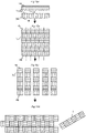
- Wood fibre based direct pressed laminated flooring usually comprises a core of a 6-12 mm fibre board, a 0.2 mm thick upper decorative surface layer of laminate and a 0.1-0.2 mm thick lower balancing layer of laminate, plastic, paper or like material.
- a laminate surface generally comprise two paper sheets, a 0.1 mm thick printed decorative paper and a transparent 0.05-0.1 mm thick overlay paper applied over the decorative paper and intended to protect the decorative paper from abrasion.
- the print on the decorative non-transparent paper is only some 0.01 mm thick.
- the transparent overlay which is made of refined ⁇ -cellulose fibres, comprises small hard and transparent aluminium oxide particles. The refined fibres are rather long, about 2-5 mm and this gives the overlay paper the required strength. In order to obtain the transparency, all natural resins that are present in the virgin wood fibres, have been removed and the aluminium oxide particles are applies as a very thin layer over the decorative paper.
- the surface layer of a laminate floor is characterized in that the decorative and wear properties are generally obtained with two separate layers one over the other.
- the printed decorative paper and the overlay are impregnated with melamine resin and laminated to a wood fibre based core under heat and pressure.
- the small aluminium oxide particles could have a size in the range of 20 - 100 microns.
- the particles could be incorporated in the surface layer in several ways. For example they could be incorporated in the pulp during the manufacturing of the overlay paper. They could also be sprinkled on the wet lacquer during impregnation procedure of the overlay or incorporated in the lacquer used for impregnation of the overlay.
- the wear layer could also be produced without a cellulose overlay.
- melamine resin and aluminium oxide particles are applied as a lacquered layer directly on the decorative paper with similar methods as described above.
- Such a wear layer is generally referred to as liquid overlay.
- the most common core material used in laminate floorings is fibreboard with high density and good stability usually called HDF - High Density Fibreboard. Sometimes also MDF - Medium Density Fibreboard - is used as core. Other core materials such as particleboard are also used.
- HDF is produced as follows: Roundwood such as for example pine, larch or spruce are reduced to wood chips and then broken down into fibres in a refiner. The fibres are thereafter mixed with a binder and then subjected to high pressure and temperature to form a board.
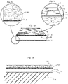
- the visible surface of the installed floor panel is called “front side”, while the opposite side of the floor panel, facing the sub floor, is called “rear side”.
- the sheet-shaped material that comprises the major part of a panel and provides the panel with the required stability is called “core”.
- core When the core is coated with a surface layer closest to the front side and preferably also a balancing layer closest to the rear side, it forms a semi-manufacture, which is called “floor board” or “floor element” in the case where the semi-manufacture, in a subsequent operation, is divided into a plurality of floor elements.
- floor board or “floor element”
- the floor elements are machined along their edges so as to obtain their final shape with the joint system, they are called “floor panels”.
- surface layer are meant all layers which give the panel its decorative properties and its wear resistance and which are applied to the core closest to the front side covering preferably the entire front side of the floorboard.
- decorative surface layer is meant a layer, which is mainly intended to give the floor its decorative appearance.
- Weight layer relates to a layer, which is mainly adapted to improve the durability of the front side.
- horizontal plane is meant a plane, which extends parallel to the outer part of the surface layer.
- horizontal plane is meant parallel to the horizontal plane and by “vertically” is meant perpendicularly to the horizontal plane.
- up is meant towards the front side and by “down” towards the rear side.
- the wear resistant transparent layer which is used in many floors, especially laminate floors, is generally placed on top of a decorative printed paper or on top of a decorative printed surface that is applied to a wood fibre based core.
- the decorative layer will be destroyed when the thin and transparent protective wear layer has been worn out.
- Linoleum is a well-known floor covering which is made from solidified linseed oil in combination with wood flour, cork dust, limestone and colour pigments. It has a solid surface layer that combines decorative features and wear resistance. This floor has however several disadvantage. The impact and wear resistance is low and it is difficult to create advanced designs. The production cost is also rather high.
- Laminate floorings have many good properties and are more cost efficient to produce than many other floor types such as wood floorings and stone floor. Many improvements have been made since the floor was invented in March 1977. The production is however still very capital intensive and comprises many steps such as:
- Laminate floorings could be produced with very advanced designs where a printed pattern is coordinated with an embossed structure of the surface.
- the embossing is made during lamination when the surface is pressed against a steel sheet with an embossed structure. This requires that the steel sheet and the printed paper are positioned accurately in a pre-determined position. Special cameras must be used to obtain the positioning and uncontrolled swelling of the decorative paper during impregnation creates major problems.
- the depth of the embossing is limited by the paper that could be damaged when the embossing is made with sharp edges or to a depth, which exceeds a few tenths of a millimetre.
- Embossed surfaces similar to a rough stone surface or a hand scraped wood surface or deep grooves that could be used to make bevels in a panel are not possible to make with the present pressing technology and with a reasonable cost structure maintaining the present technical properties and design.
- Wood fibre based floorings similar to laminate floorings and direct printed floorings could capture a considerable larger market share if the wear and impact resistance could be increased, if one or several production steps could be eliminated and if more attractive designs could be obtained.
- document DE 202 14 532 U1 can be mentioned.
- This document discloses a cover plate for building interiors, in particular, for covering floors, walls or ceilings.
- the cover plate comprises a core of MDF or HDF and a surface layer of a non-woven mat consisting of renewable raw materials, especially hemp, flax, oil linen, jute, sisal and the like.
- an overlay can be formed by scattering of a melamine resin powder with anti-abrasive particles over the non-woven mat.
- GB 984,170 discloses a method of making a chipboard having a smooth surface.
- a chipboard manufactured in accordance with the disclosed method in GB 984,170 has a surface which is prepared to have a design printed directly thereon.
- EP 1 690 603 discloses a method for applying a liquid synthetic resin-fibre mixture to a derived timber board, wherein the fibres are mixed into a liquid synthetic resin.
- EP 1 584 378 discloses a method to coat a substrate with a melamine-formaldehyde resin, wherein a layer of powderous melamine-formaldehyde resin is applied on a substrate and melted by IR- or NIR-radiation, and pressing the laminate in a laminating press.
- US 5,422,170 discloses a method of manufacturing wood based panels, wherein wood fibres are mixed with inorganic filler or inorganic cellular material. An organic binder or an aqueous solution thereof is applied evenly over the mixture of wood fibre and inorganic filler. The resulting dry mixture of wood fibres and binder is scattered on a hot press platen to form a surface layer. A further dry mixture of wood fibres and binder is scattered on the surface layer to form a core layer. A further dry mixture is scattered on the core to form a second surface layer. The three layered preformed material is then hot pressed to give an integrally formed wood based panel. The panel may contain pigments.
- US 3,673,020 discloses a process for the manufacture of particle boards utilising a dry organic binder, wherein sawdust having a particle sixe below 1 mm is mixed with a quantity of binding agent ranging between 5% and 15% of the weight of the dry sawdust.
- An overall objective of embodiments of the disclosure is to provide a building panel, preferably a floor panel, which has better properties and/or cost structure than the known building panels.
- a first objective of embodiments of the disclosure is to provide a fibre based panel, preferably a floor panel, with a wear layer, which has a higher wear resistance and preferably also a higher impact resistance than the present wood fibre based floorings.
- a second objective of embodiments of the disclosure is to provide a fibre based flooring and a production method to produce such flooring wherein the floor panel is produced in a more cost effective way than the known floor types and where one of several production steps are made in a more cost effective way or completely eliminated.
- a third objective of embodiments of the disclosure is to provide a fibre based floor with new attractive design features which preferably could be combined with high wear resistance and cost effective production.
- a fourth objective of embodiments of the disclosure is to provide core materials and surface layers or combination of surface layer and core which could be used to make panels, preferably floor panels, with more favourable cost structure and/or design and/or properties such as wear, impact and sound.
- a building panel comprising a surface layer and a core, which comprises wood fibres.
- the surface layer comprises a substantially homogenous mix of wood fibres, comprising natural resins, a binder and wear resistant particles.
- Embodiments of the disclosure offer several advantages over known technology and especially over conventional laminate floorings.
- the wear resistant particles are preferably aluminium oxide particles.
- Other suitable materials are for example silica or silicon carbide. In general all materials with a hardness of Rockwell C hardness HRC of 70 or more could be used.
- Embodiments of the disclosure offer the advantage that the wear resistant surface layer which is a homogonous mix and not separate layers, could be made much thicker and a wear resistance, which is 5 - 10 times better than in the present laminate floors could be reached. It is possible to make a wear resistant surface layer where abrasion of the surface will only reduce the thickness with for example 0.10 mm for each 10,000 revolutions. 50,000 revolutions will only decrease the thickness with about 0.5 mm and the wear resistance and the decorative properties will be maintained.
- the wear resistant particles are preferably aluminium oxide and the binder is preferably a synthetic thermosetting resin such as for example a melamine resin.
- Decorative effect could be obtained with wood fibres, other types of fibres and/or decorative wear resistant particles only.
- the decorative effects are however in the most preferable embodiments obtained by colour pigments that are applied into the homogenous surface layer.
- Wood fibres in the surface layer comprising natural resins, for example lignin, could be of the same type as used in HDF or particleboard. They are therefore opaque and not transparent as in an overlay paper sheet. The raw material price for such fibres is much lower than for ⁇ -cellulose fibres where the natural resins have been removed in the production process in order to obtain transparency.
- a particularly preferred embodiment is a floor panel comprising a surface layer and a wood fibre based HDF or particleboard core.
- the surface layer comprises a substantially homogenous mix of wood fibres, comprising natural resins and of the same type as used in HDF or particleboard, a binder of a synthetic thermosetting resin, aluminium oxide particles and colour pigments.
- the surface layer could comprise of for example about 25% (weight) aluminium oxide, about 25% wood fibres, about 25% melamine formaldehyde resin and about 25% colour pigments.
- the surface layer could have a thickness, which is for example in the range of 0.1 mm - 3 mm or even more. Other combinations are of course also possible.
- the melamine part could vary for example between 10 - 35%.
- the content of the colour pigments could be very low for example only about 0.1-5%.
- Wear resistant particles could be in the same range and could for example vary from a few percent to 35% and even higher.
- the mixture should be adapted to the desired properties and cost structures.
- the binders contribute in general to give the surface a high impact and moisture resistance but they are rather costly. Some wear resistant particles are also rather costly. Wood fibres and other fibres are in general rather cheap, especially if they are derived from recycled material.
- the wear resistant particles for example aluminium oxide, give only a very limited contribution to the impact resistance in a laminate floor since they are only applied as a very thin layer (0.1 mm) and the content is generally only about 10 - 30 gram/m2.
- the disclosure gives however the possibility to use much more particles in the solid homogenous surface layer and such particles could also increase the impact resistance of the floor considerably.
- the wear resistant particles are preferably distributed at random and fixed in the surface layer by fibres and binders that surround them. It could be mentioned as a non restricted example that a 0.5 - 1.0 mm surface layer according to the disclosure could comprise for example 100 - 400 gram/m2 of wear resistant particles and even higher. It is obvious that there is no lower limit and even rather small amounts could be sufficient in some applications if such particles are incorporated at least partly into the fibre structure.
- a wear resistant and decorative surface layer could be formed in several alternative ways. It is possible to produce a strong surface layer with small amounts of wear resistant particles by for example increasing the content of the binder and /or incorporating fibres, preferably wear resistant fibres that could be used to replace a part of the wear resistant particles. Plastic fibres, for example nylon fibres or mineral fibres such as glass fibres, could improve the wear resistance considerably in a homogenous surface layer material.
- a building panel comprising a surface layer connected to a core, which comprises wood fibres.
- the surface layer which gives the panel decorative effects and wear resistance, is a homogenous layer comprising parts of fibres, colour pigments, a binder and wear resistant particles.
- the wood fibres in the surface layer are according to this second aspect completely or partly replaced with other fibres.
- Preferable embodiments comprises fibres such as vegetable fibres for example jute, linen, flax, cotton, hemp, bamboo, bagasse and sisal and such fibres could be mixed with wear resistant particle, for example aluminium oxide, to create a vegetable fibre based wear resistant surface layer.
- Plastic fibres for example nylon fibres or mineral fibres such as glass fibres could also be used in specific preferred embodiments. All fibres mentioned above could be mixed together for example wood/bamboo, nylon/glass fibres etc. Ceramic bubbles could be mixed with fibers in order to for example increase the thermal insulation and acoustical absorption. Such particles could also be non-flammable.
- Wood fibres in the core could also partly or completely be replaced with plastic fibres, mineral fibres or vegetable fibres in the same way as described above for the surface layer.
- thermosetting binders are preferred but thermoplastic binders could also be used. It is preferred to have the same type of binder in the core and the surface in all embodiments of this disclosure but combinations are not excluded for example a thermosetting binder in the core and a thermoplastic binder in the surface layer or the opposite.
- a surface layer which comprises wear resistant particles with high density, for example aluminium oxide, and where such particles are distributed over a substantial thickness of the surface layer, for example 0.2 - 1.0 mm, as described above could have a density which is higher than the present laminate surfaces, especially if such a layer also comprises a high degree of binders.
- Such surface layer could have a density of 1500-2000 kg/m2 or even higher and the impact resistance could be considerable higher than in traditional laminate floorings where aluminium oxide is only used in very thin well defined overlays with a thickness below 0.10 mm.
- the density could be lower but should preferably not be lower than 1000kg/m3.
- Sufficient impact resistance could be obtained with a high density surface layer even with a rather soft core material such as MDF or particleboard.
- the high density could also give the floor a sound and feeling, which is similar to a real stone floor.
- the core could also be produced with high density especially if small compact fibres are mixed with a high amount of binders and pressed under high pressure. It is obvious that all preferred embodiments of the first aspect could be combined with the preferred embodiment of the second aspect. This means for example that the same pressure, pressing times, binders, fibres, wear resistant particles, material compositions etc could be used.
- a production method comprising the steps of:
- This production method could be used to produce all embodiments of the disclosure.
- the production method is in a preferred embodiment based on a surface layer comprising wood fibres, aluminium oxide and a thermosetting resin wherein the surface layer is formed and connected to a HDF core or a particle board core in a pressing operation such that it forms a floor board.
- This preferred production method comprises the following steps:
- a separate balancing layer of for example impregnated paper could preferably also be applied on the rear side of the core during the pressing.
- Colour pigments are provided to create an attractive design. Decorative effect could be obtained with different fibres or wear resistant particles only. Aluminium oxide could for example be produced in different colours.
- the binder is preferably a melamine-formaldehyde or urea-formaldehyde or phenol- formaldehyde resin or combinations of these resins.
- the pressure is preferably about 300N - 800N/cm2 and the temperature could be 120-220 degrees C.
- the pressing time could vary for example from 20 seconds to 5 minutes. It is possible to use very short pressing times, for example about 10 seconds or shorter, especially in embodiments where a rather thin fibre layer is applied on an HDF core before pressing.
- Thermoplastic binders such as PVC, PE, PP, etc could also be used. Other possibilities are for example natural resins such as sugar or lignin.
- the production method could preferably comprise an intermediate pressing step where the fibres are partly compressed but not cured. Printing or application of decorative materials could be made between the intermediate and the final pressing.
- Decorative features could also be applied after the curing.
- Laser could for example be used to engrave the surface and decorative grooves could be made such that surface material is removed to a lower part of the surface, which comprises a layer with a different colour or design than the upper surface portion. Further heat and pressure could be applied to change the colour or to create further embossing of the surface.
- Laser could also be used prior to final pressing in order to create decorative patterns and effects such as dark lines or spots that for example are used to copy wood or stone.
- the method could be used to produce a whole floorboard.
- the method could also be used to produce an upper and/or lower layer, which is applied on a known fibreboard or particleboard core, preferably a HDF core.
- the method could also be used to produce individual floor elements and even the finished floor panels where the edges and even parts or the whole locking system could be formed during pressing.
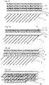
- the whole panel is made in a continuous production line where fibres, binders, colour pigments and wear resistant particles or fibres are applied in preferably at least three layers with different material compositions in order to form a panel with a core and a surface layer.
- a preferred embodiment not presently claimed where the surface layer and the core are integrally formed, continuously or discontinuously, in substantially the same pressing operation is referred to as "integrally formed panel" or IFP.
- the lower layer or part could be a balancing layer comprising substantially wood fibres and binders only, which are adapted to balance the surface layer.
- the balancing layer could also be applied as a separate pre fabricated material that could be fused to the core during pressing.
- the middle layer or middle part is preferably a core layer comprising wood fibres and binders only and the upper layer is a surface layer comprising wood fibres, colour pigments and wear resistant particles or chemicals.
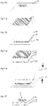
- the layers are preferably applied and transported on a conveyor belt and optionally pre-pressed from an initial thickness of for example 30-50 mm to an intermediate thickness of for example 10-20 mm.
- a decorative pattern could than be applied in line on the pre-pressed surface with for example an ink jet digital device which allows the ink to penetrate into the pre pressed surface.
- the board is finally pressed under heat and pressure to a thickness of for example 4-10 mm in preferably a continuous pressing operation at the end of the production line where optionally a sanding of the lower balancing layer could be made in order to obtain an accurate thickness if necessary.
- An IFP panel could also be produced in a production line comprising a discontinuous press of the conventional type generally used in laminate floor production.
- the core, the surface layer and preferably also the balancing layer are formed and connected to each other in the discontinuous press.
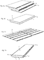
- the production as presently claimed is made in a two-step process where the production steps to obtain a core and a surface layer are performed in two separate operations.
- This production method is referred to as "surface on core” production or SOC.
- a core of a wood fibre based board such as for example HDF, MDF, particleboard, OSB, plywood and similar sheet materials could be produced in the conventional way.
- a lower and/or upper layer, comprising the surface layer and optionally also the balancing layer, is thereafter applied to the core with scattering equipment and this could be integrated with the steps that give the surface its decorative properties.
- a separate balance layer could be applied in a separate production step.
- the core with preferably the upper and lower layers is thereafter pressed in a continuous or discontinuous press such that the upper surface layer and optionally even the balancing layer are cured and laminated to the pre-fabricated core.
- All types of wood fibre based boards could be used for the core and the method is very suitable even for soft core materials and core materials with rough surface portions.
- the decorative surface layer could fill up irregular surface portions in the core and reinforce the core such that an impact resistant panel is obtained with any kind of decorative surface structures. This decorative surface is not affected by the core surface as in traditional laminate and wood veneer floorings.
- the core material and an upper surface layer or lower balancing layer could according to an unclaimed alternative also be produced separately in three production steps and the separate layers could be connected to the core by for example gluing.
- a separate wood fibre or fibre layer which could be used primarily as a surface layer but of course also as a balancing layer, hereafter referred to as "separate surface layer” or SSL, could be produced continuously or discontinuous in thickness of for example 0.3 - 2 mm.
- Such a surface layer could be used to replace laminate sheets, wood veneer or wood layers in laminate and wood floorings with for example a core of HDF, MDF, particle board, plywood, lamella wood core and similar.
- the surface layer could have a high density and impact resistance even if it is combined with rather soft core materials.
- IFP Fibre Composite Floor
- SOC SOC
- SSL SSL
- a floor is in this application generally referred to as a Fibre Composite Floor or FCF.
- FCF Fibre Composite Floor
- It could be produced as described above with continuous or discontinuous presses and the production steps could be combined in parts.
- a pre curing and a final curing with various intermediate steps are also possible to use.
- the decorative properties could be obtained in several ways.
- the surface is in one embodiment made decorative by colour pigments, which preferably are mixed into wood fibres.
- the whole panel could be coloured.
- colour pigments in powder form are mixed with fibres, example wood fibres, and binder in powder form and small wear resistant particles in the upper layer.
- a printed pattern could be provided on the basic colour.
- the printing should be made preferably before the final pressing and curing operation and this will allow the print to penetrate deep into the upper fibre layer.
- the print could be applied in such a way that it extends a considerable distance, for example 0.1-1.0 mm, into the upper fibre layer after pressing. Vacuum could be used to facilitate and to guide the penetration of the print into the basic fibres.
- Such a print could create very accurate copies of stone and wood products and it will maintain its pattern even when the surface layer has been worn down considerably.
- a very durable, decorative and wear resistant surface could be created in a very cost effective way. Fine and well-distributed fibres in the surface layer make it possible to create very distinct and accurate wear resistant printed patterns.
- the decorative effects could also be obtained with rather soft separate materials, for example different types of fibres, chips or particles of wood, textiles, plastic, cork, and similar which optionally could be mixed with colour pigments and applied by for example scattering or extrusion as a protruding pattern on the basic fibre surface before the final pressing.
- Fibres could also be used to improve mechanical properties.
- Mineral fibres such as for example glass fibres could increase the strength and flexibility and improve resistance against heat and fire.
- Natural fibres could also have a positive impact on the properties. Variations in the fibre orientations could be used to increase the decorative effects.
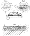
- Separate materials applied on the basic surface will after pressing penetrate into the basic surface fibres. The penetration could be controlled very accurately. A hard material composition will penetrate deep into the softer basic fibres. A softer separate material will be more compressed and distributed over a larger surface area.
- the separate materials should preferably have a different size and/or structure and/or orientation and/or optical effects than the basic fibres and they will automatically create a perfect fit between a desired pattern and a surface structure. The design effects could be even more pronounced if the separate materials have different wear resistance than the basic fibre structure.
- the surface could be brushed and the different fibre structures will be more visible as in real wood or stone floors. A similar effect could be obtained if the printing paint comprises wear resistant particles, which are applied locally during the printing process.
- the surface could comprise particles that could swell, expand or shrink after pressing and thereby create an uneven or embossed surface. All these design effects could be maintained when the surface is subject to considerable wear during a long period of time since they extend deep into the surface layer. Repetition effects of a printed pattern could be avoided.
- Special hard wear resistant and decorative non wood fibre based materials could also be incorporated into the surface for example synthetic diamond powder or diamond particles preferably with a size of 0.01-0.10 mm. Such diamond particles could also increase the wear resistance and improve friction properties of the floor.
- Other alternatives are metal powder or flakes, stone powder, ceramic powder or particles, sand and other similar known decorative materials.
- Nano particles could also be incorporated and this could for example be used to give the surface improved properties related to glossiness, cleanability, UV stability, friction, wear resistance etc.
- the invention does not exclude additional transparent or non-transparent layers, coating or similar over the basic fibre structure.
- the design effects could also be used independently in a fibre panel that does not comprise wear resistant particles or colour pigments. In this case the wear resistance could be created with wood fibres and binders only.
- Special decorative effects and mechanical properties could be obtained with a surface layer comprising fibres of different wood types or combinations of two or more wood species for example any combination of oak, ash, maple, beach, pine, spruce, birch, merbau or similar. These different wood fibres could also be coloured, heat-treated or modified in similar ways before they are applied as a surface layer.
- Advanced decorative effects could be obtained with fibres and decorative particles that could be applied and positioned electrostatically. This method makes it possible for example to position and orient wood fibres and to create a structure similar to a wood veneer. Gravity and airflows could also be used to distribute fibres and particles in a controlled way.
- Cork material in the form of small particles or dust could also be used to partly or , in contradiction to the claimed invention, completely replace wood fibers in all embodiments of the disclosure
- cork could be used as a surface or backing layer in a floorboard.
- the layers could be made from granules of cork that are glued or they could be in the form of a cork veneer.
- the cork is used mainly to reduce sound but also for decorative purposes.
- cork granules could be mixed into for example concrete in order to obtain low thermal conductivity, low density or good energy absorption.
- cork dust could be mixed with a binder, preferably a synthetic thermosetting binder, and wear resistant particles to form a surface layer in a floorboard.
- a building panel comprising a surface layer and a core, which comprises wood fibres or cork particles.
- the surface layer comprises a substantially homogenous mix of cork particles, a synthetic binder and wear resistant particles.
- the core could be a traditional wood fibre based core, for example HDF or similar or it could be a core comprising partly or completely cork particles and a binder, preferably a thermosetting binder. Colour pigments could be included.
- a particularly preferred embodiment is a floor panel comprising a surface layer and a core, which comprises wood fibres or cork particles.
- the surface layer comprises a substantially homogenous mix of cork particles, comprising natural resins, a synthetic thermosetting binder and wear resistant particles of aluminium oxide.
- the density of the cork surface layer is preferably 800 - 1400 kg/m3 and the density of the core could be 600 - 1000/m3.
- Embodiments of the disclosure offer the advantage that the surface layer could be made more flexible and softer than in traditional laminate floorings and this could be combined with a maintained or even improved wear and impact resistance. This could also result in a more attractive sound level and lower thermal conductivity. The result could be a more silent and warmer floor.
- a floor panel comprising cork particles could be produced according to the same three basic embodiments, IFP, SOC and SSL as described above.
- the principles of the disclosure could also be used to produce a core comprising cork that could be used to replace a traditional wood fibre based core for example a HDF panel.
- cork chips with a size of 2-5 mm could be glued together with very low pressure to panel with a density that does not exceed 300kg/m3. It is not known however that very small cork particles, for example smaller than 1.0 mm, could be mixed with a thermosetting binder and pressed together with high pressure to form a high-density panel that could for example be used as a core material in a floor panel.
- a building panel comprising small cork particles and a thermosetting binder that are pressed together to a panel with a density exceeding 600 kg/m3.
- a cork particle based core could be used together with a surface layer comprising cork particles or a surface layer according to the first and second aspects of the disclosure but it could also be used as a core in a floor with traditional surface layers.
- a cork core or surface layer could have properties, for example moisture resistance, shearing strength, density and impact resistance similar to or even better than normal HDF material and it is possible to form a strong and a high quality locking system in the cork core edge.
- the flexibility of the cork particles makes it possible to reach a high impact resistance.
- the properties are mainly achieved by mixing a thermosetting resin, for example melamine in powder form with small cork particles, preferably with a size of a few tenths of a millimetre or even smaller down to some hundredths of a millimetre, which are thereafter pressed with a pressure of about 300 - 400 N/cm2 and a temperature of 140 - 180 degrees C.
- the cork core could be used in combination with known surface materials such as laminate, resilient surfaces, fibre based surfaces, wood, wood veneer, linoleum, cork veneer, wall to wall carpets and similar.
- surface materials such as laminate, resilient surfaces, fibre based surfaces, wood, wood veneer, linoleum, cork veneer, wall to wall carpets and similar.
- a thin surface layer for example a wood veneer could be applied, prior to pressing, on a sub layer comprising cork particles and binders. Pressing could take place against a press plate, which could create a deep embossing, or deep grooves.
- the thin surface layer will be formed and laminated to the sub layer.
- the thin surface layer will not be damaged since the cork particles will be compressed and formed according to the structure of the press plate.
- This forming technology could also be used in a panel where the sub layer comprises wood firers or other type of fibres that could be formed by pressing.
- a combination core or panel could also be produced with different layers that comprise only cork particles or wood fibre particles or a mixture of wood fibres and cork particles.
- a dry process where the different materials and mixtures of different materials such as fibres, wear resistant particles, binders and colour pigments are distributed and scattered in a dry form.
- a liquid or semi liquid process where for instance the binder is mixed into the fibres or particles in liquid form is however not excluded. Scattering could be made with several stations comprising embossed or engraved rollers and brushes that could apply one or several layers of preferably dry materials.
- All embodiments with and without wear resistant particles could be used to make panels, which could be applied vertically on a wall as wall panels in interior or exterior applications.
- Such panels could have a mechanical locking system on long edges that is possible to lock with angling and on short edges a locking system with for example a flexible tongue that allows vertical folding as described in for example WO 2006/043893 .
- Figure 1a shows a laminated floor panel 1 according to known technology comprising a surface layer 5, a core 6 and a balancing layer 7.
- Figure 1c shows the surface layer 5. It has an upper wear layer 13 of a transparent material with great wearing strength.
- a wear layer comprises generally a transparent paper (overlay) impregnated with melamine resin and with aluminium oxide particles 12 added. Aluminium oxide particles are generally positioned in the lower part of the overlay in order to protect the press plates from wear during pressing.
- a decorative layer 10, comprising of paper with a printed pattern 11 is impregnated with melamine resin and placed under this transparent wear layer 13.
- the wear layer 13 and the decorative layer 10 are laminated to the core, generally a fibre based core such as HDF, under pressure and heat to an about 0.2 mm thick surface layer 5.
- Figure 1b shows the balancing layer 7 that generally also is a melamineimpregnated paper. This balancing layer keeps the floor panel flat when humidity varies over time.
- the transparent wear layer is generally 0.05 - 0.10 mm thick. The decorative printed pattern 11 will be destroyed when the wear layer is worn out.
- Figure 1d shows in detail the upper surface part of a conventional laminate floor as explained above.
- the aluminium oxide particles 12, which are transparent, are included in the pulp during the production of the transparent overlay 13.
- Figure 2a shows a known surface layer with multiple overlays 13 that have a coordinated print on the lower side in order to improve wear properties.
- the layers are also in this surface layer placed over a decorative layer 10.
- Figure 2b shows a known overlay, which generally is semi transparent, coloured with colour pigments 15 and placed on a decorative layer 10.
- All overlays are made of refined ⁇ -cellulose fibres.
- all natural resins that are present in the virgin wood fibres have been removed.
- the known surface in a laminate floor is in all embodiments made up of well-defined paper layers with constant thickness. Separate layers are used to accomplish the decorative properties and the wear properties. The total thickness of all wear resistant layers does not exceed 0.2 mm.
- Figure 2c shows a known direct print on a HDF panel.
- a base colour 16 comprising colour pigments 15 is applied on a core 6.
- a print 11 is applied on the base colour and protected against wear by a transparent varnish 18 and in some applications even with a top coating layer 17 that could comprise aluminium oxide.
- Such a surface layer is colour based and no fibres are used.
- Figure 2d shows a known coloured HDF panel where colour pigments are 15 are included in the core.
- the surface is covered with a transparent top coating layer 17. The wear and impact resistance of such a panel is low.
- Figure 3a shows a floor panel 1 according to one embodiment of the disclosure.
- a panel 1 is provided with a wood fibre based core 6, a homogenous non-transparent decorative surface layer 5 and preferably a balancing layer 7.
- the panel 1 is integrally formed in a production process where the surface layer, the core and the balancing layer are formed in the same pressing operation.
- Figure 3b shows the surface layer 5. It comprises a mixture of wood fibres 14, small hard wear resistant particles 12, 12' and a binder 19.
- the wood fibres are unrefined, of the same type as used in HDF and particleboard and they comprise natural resins such as lignin.
- the wear resistant particles (12,12') are preferably aluminium oxide particles.
- Other suitable materials are for example silica or silicon carbide.
- Diamond crystals or powder could also be added into the surface layer. In general all materials with a hardness of Rockwell C hardness HRC of 70 or more could be used and they do not have to be transparent. A mixture of two or more materials could be used.
- the connection 34 between the core 6 and the surface layer 5 is not a distinct layer, as can be seen in Figure 3b due to the fact that fibres of the two layers are mixed are fused together. This gives a very strong connection between the core and the surface layer.
- the surface layer comprises preferably also colour pigments 15 or other decorative materials or chemicals.
- Embodiments of the disclosure offer the advantage that the wear resistant surface layer 5 could be made much thicker than in the known floor panels.
- the thickness of the wear resistant and decorative surface layer could vary from for example 0.1-0.2 mm to for example 2-4 mm or even more. Wear resistance with maintained decorative properties could be extremely high, for example in the region of 100,000 revolutions and more in a surface layer that is about 1.0 mm thick.
- Such a panel could be used as a floor panel but also as a component in a machine, car etc. where a high wear resistance is required and complex injection moulded or extruded components could be formed which also could be reinforced with for example glass fibres.
- the surface layer comprises a vertical portion P with a first upper horizontal plane H1, located in the upper part of the surface layer that comprises a first wear resistant particle 12. It has a second intermediate horizontal plane H2, located under the first wear resistant particle 12 that comprises wood fibres with natural resins. It has a third lower horizontal plane H3, located under the second horizontal plane H2 that also comprises a second wear resistant particle 12.
- the fibres and wear resistant particles could preferably be mixed with colour pigments. Such an embodiment will give a very wear resistant surface layer that will maintain its decorative properties. The surface will be undamaged when the abrasion has removed the first upper fibres to the second horizontal plane H2. Only about 0.1 mm of the surface will be removed.
- the abrasion will then remove material to the second horizontal plane H2 and the surface will still maintain its decorative properties.
- the abrasion must remove materials to the third horizontal plane and only then, provided that there are no further horizontal planes comprising wear resistant particles or colour pigments, will the surface change its decorative properties.
- the surface layer could comprise many horizontal planes adjacent to each other and located at different distances from the front side of the panel, for example 0.1 mm, 0.2 mm, 0.3 mm, 0.4 mm, 0.5 mm etc and they could comprise wear resistant particles or wood fibres.
- Embodiments of the disclosure offer the advantage that a wear resistance, which is considerably better, for example 5-10 times better than in the present laminate floors, could be reached.
- Abrasion of the surface will only reduce the thickness of the surface layer.
- the wear resistance and the decorative properties will be completely or essentially maintained or changed in a controlled and pre determined way.
- a preferable binder is melamine or urea formaldehyde resin. Any other binder, preferably synthetic thermosetting resins, could be used.
- Figure 3c show that a balancing layer 7 comprising preferably wood fibres 14' and a binder could be provided on the lower side of the floor panel.
- the fibres, the binder and also the pressing temperature should be adapted in an appropriate way to balance the surface layer and to keep the panel flat.
- the balancing layer 7 is preferably pressed with a higher temperature for example 5-20 degrees higher than the surface layer 5
- the surface layer could comprise of for example 25% (weight) aluminium oxide, 25% wood fibres, 25% melamine resin and 25% colour pigments.
- the surface layer could have a thickness, which is for example in the range of 0.1 mm - 3 mm or even more. The most preferable thickness is 0.5 - 1.5 mm.
- Figure 3d show a panel where the surface layer 5 has been formed on a core 6 that has been produced in a prior separate operation according to the SOC principle.
- the connection 34 could be very strong since binders 19 from the surface layer 5 penetrate into the upper part of the core 6, especially if the core is HDF or a wood based panel such as for example particleboard.
- the binders 19 in the surface layer 5 could be specially adapted to penetrate and reinforce the upper parts of the core in order to for example increase the moisture resistance. Different binders or binder contents could be used in the upper and lower parts of the surface layer 5.
- FIGS 4a, 4b and 5a schematically show preferred production methods, which could be used to produce a fibre based panel.
- the methods are described schematically and with the surface layer as the upper layer. It is obvious that the production could take place with the surface layer as a lower layer.
- Figure 4a shows production of a panel, preferably a floor panel according to the preferred IFP principle.
- a scattering station is used to apply a first layer 7, comprising the balancing layer, on a conveyor 20.
- a second layer 6 comprising the core layer is applied on the balancing layer in the same way.
- These two layers comprise preferably wood fibres and a binder only.
- a third layer, the surface layer 5, is applied by the scattering station on the core layer 6.
- the surface layer 5 comprises preferably wood fibres, a binder and wear resistant particles.
- the surface layer 5 comprises preferably also a colour pigment that gives the surface layer a basic colour.
- the production method could preferably comprise an intermediate pressing step, where the wood fibres are partly compressed with a roller 21 or with continuous pressing equipment or a similar device.
- the fibres are preferably not cured, at least not completely, at this intermediate production step.
- the scattering station 60 could comprise several scattering units 60a, 60b, 60c, one for each material composition.
- An advanced production line could comprise up to ten scattering units and even more.
- Printing, colouring and similar design effects on the surface with for example an ink jet printer 22 or similar production equipment that gives the surface layer 5 decorative features could be used in line with the production of the floorboard.
- Printing is preferably made on a pre pressed surface prior to the final pressing.
- a scattering station could also be used after the pre pressing in order to for example apply additional decorative particles.
- a second pre pressing and even further applications of decorative materials could be made prior to the final pressing.
- the pre pressed layers are after printing, if such production step is used, pressed under heat and pressure and the fibres and the wear resistant particles are bonded together with the binder, which cures under heat and pressure.
- a panel with a hard and decorative surface layer is obtained.
- Continuous pressing is preferred but discontinuous presses with one or several openings could also be used.
- Pressing could take place against an embossed pressure matrix such as a steel belt 23, an embossed sheet or a paper-based embossed matrix in order to create an embossed surface that optionally could be coordinated with the surface design.
- High quality coordinated design and embossing could be obtained with an integrated pressing and design method which is not used in the flooring industry since all such design features are based on two separate steps of printing and pressing.
- an integrated pressing and design "stamp” method could be used whereby an embossed pressure matrix comprising protrusions, which are covered with a selected paint, for example with a rubber roller that applies the paint only on the protrusions and not on the matrix parts located at lower portions between the protrusions, could be used.
- a selected paint for example with a rubber roller that applies the paint only on the protrusions and not on the matrix parts located at lower portions between the protrusions
- the "stamp” method is described more in detail in Figures 16a-e .
- the paint and the pressing could be chosen such that the paint penetrates into the fibre structure during the initial part of the press cycle.
- the same method could be used to apply other materials than paint for example special fibres or particles on protrusions located on a pressing matrix and to apply them into deeper structures than the top parts of the surface.
- the binding agent is preferably a melamine- formaldehyde resin.
- the pressure is preferably about 300N-800N/cm2 and the temperature could be 120-220 degrees C.
- the pressing time could vary for example from 20 seconds to 5 minutes depending on the production speed, panel thickness, binders etc.
- the density of the floorboard is preferably 700-1000 kg/m3. It is possible to produce very moisture and impact resistant floorboards with a density of 1000-1500 kg/m3.
- the surface layer may comprise or consist of wood fibers that are essentially smaller than 1 mm.
- the surface layer may comprise or consist of wood fibers in powder form that are essentially smaller than 0.5 mm.
- the surface layer comprises preferably or consists of fibres in wood powder form with particles, which are in the range of about 0.1-0.3 mm or even smaller.
- the fibre particles in the core part could be 0.1-1.0 mm or even larger.
- a particularly high quality surface layer 5 could be achieved if the wood fibres, which are mixed with the binder, colour pigments and wear resistant particles, are already pre coated and fully or partly pre cured with a binder, for example a melamine or urea formaldehyde resin, or pressed and than separated mechanically into wood fibre powder or wood fibre chips which are preferably smaller and more compact than the original wood fibres.
- a binder for example a melamine or urea formaldehyde resin
- Such a fibre composition is especially well suited to be mixed with wear resistant particles and could create a compact and well-defined base for the printing operation.
- the wear resistant particles could be evenly spread over the whole surface layer and a high wear and scratch resistance could be reached.
- Such coated fibres could be obtained from recycled HDF or HDF based laminate floorings, which could be mechanically cut and separated to small wood fibre chips and/or wood fibres.
- the chips and fibres could be used in all layers (5, 6, 7) even if they comprise aluminium oxide or small melamine/paper flakes.
- the wood fibres could also be separated from the melamine and paper particles and used as melamine coated fibres in the surface 5 and/or in the core 6 and/or the balancing layer 7.
- FIG. 4b shows substantially the same production method, which in this preferred embodiment is used to produce a SOC panel.
- a balancing layer 7 is applied on a conveyor.
- the balancing layer could be a wood fibre based layer as described above or a traditional balancing paper used in conventional laminate flooring production.
- a pre fabricated core 6, for example a HDF or a particleboard or any other type of board is placed over the balancing layer.
- a surface layer 5 is applied with a scattering station 60 on the core, according to the same method as described above, and the upper and lower layers are connected to the core in a press such that a panel is formed with a surface layer 5, a core 6 and a balancing layer 7.
- the balancing layer 7 could be decorative and could comprise wear resistant particles.
- a panel according to the disclosure could have a surface layer 5 and 5' on each side.
- Such surface layers could preferably have different designs and this will reduce the number of articles that have to be transported and stored.
- Embodiments of the disclosure are very suitable for such double-sided panels since the cost for providing the rear side with a decorative layer is very limited.
- Mechanical locking systems could be adapted to allow locking of such panels preferably with horizontal or vertical snapping.
- Figure 5a shows the SSL principle where a panel is formed which could be used as a separate surface layer.
- the production equipment is in this case used in the same basic way as in the other two methods described above.
- the main difference is that the floorboard 3 is a surface layer 5 with preferably a thickness of about 0.5 - 3 mm.
- This surface layer could be connected, preferably with glue, to any type of core material.
- Decorative features could be obtained in many alternative ways.
- the surface could comprise substantially only wood fibres and wear resistant particles.
- a design with one basic colour only could be sufficient and in such a case colour pigments are mixed with the wood fibres and no intermediate pre pressing is needed in order to form a base structure for further design steps.
- Pre pressing could however be used for other purposes as will be explained in the text below.
- Figure 5b shows that a decorative pattern could be obtained by mixing fibres with different colours 30, 31 and/or different fibre structures, fibre sizes, fibre types etc.
- Figure 5c shows an ink jet spray head 24 that could be used to apply a print 32 or a pattern similar to a print on a preferably pre pressed surface.
- the ink penetrates into the fibres prior to pressing and could be positioned deep into the cured surface after pressing.
- Ink or colour particles could be applied for example with a depth under the upper part of the surface of 0.1 -1.0 mm or even more.
- the ink should preferable penetrate to a level below the upper wear resistant particles.
- Figure 6a shows that for example an extruder 25 with an extruding head 26 could apply separate extruded fibres 33, with a different colour and/or structure and/or density and/or wear resistant properties, on the basic fibre layer.
- the extrude fibres are preferably mixed with a binder and optionally also with wear resistant particles.
- Figure 6b shows that the separate fibres 33 could be pressed and bonded into the surface layer 5.
- Figure 6c shows that the separate fibres 35 could be applied with a lower wear resistance then the basic fibre surface. The surface could be brushed and this will remove a part of the upper surface of the separate fibres 35 and a decorative groove will be obtained. This will give a perfect match between the structure and the coloured design.
- Figure 6d shows that other separate materials such as flakes 36 of wood, metal, plastic etc. could be used to give the surface decorative properties and these separate materials could be pressed into the basic wood fibre surface.
- Figure 6e shows that pressing a matrix to the surface could create grooves, bevels, grout lines and similar. Such embossing could be made much deeper than in traditional laminate floorings where the paper will be damaged. Embossing with a depth of for example 1-2 mm or even more could easily be obtained.
- Figure 6f shows that a surface design could be obtained with for example wood fibres, preferably essentially individual fibres or clusters of individual fibres that are located in patterns on the surface. They could be applied in several layers, which are coordinated such that they build up a material layer similar to real wood.
- Figure 7a shows a panel according to an embodiment of the disclosure. It comprises a surface layer 5 which is produced according to an embodiment of the disclosure and which is glued or laminated to a known core material 6. A balancing layer 7 is applied at the rear side as shown in Figure 7b .
- the floorboard 3 is produced according to the IFP, SOC or SSL principles described above.
- Figures 7c shows the floor board after it has been cut into several floor elements 2.
- Figure 7d show floor elements, which have been formed to a floor panel 1 with mechanical locking systems 4, 4' at the long edges. A mechanical locking system is generally also formed on the short edges. All known locking systems allowing locking with angling, horizontal and vertical snapping, side push etc could be used.
- the floor panels could however also have rather simple locking systems or only straight edges similar to tiles and stone and they could be glue down to the sub floor.
- Figure 8a shows a panel according to an embodiment of the disclosure that could be produced with the same basic equipment that is generally used in conventional laminate floor production.
- the panel comprises a surface layer 5, a HDF core 6 and a balancing layer 7.
- the surface layer is preferably in a powder form such that it could be scattered as a thin layer and formed to for example a 0.1 -0.5 surface layer on a pre fabricated fibre based core, preferably a 6-8 mm HDF core.
- the binder could be adapted such that pressing could be made in conventional continuous or discontinuous direct lamination presses with pressing times, temperature and pressure similar to the parameters used today.
- the thickness of the surface layer could vary but it is preferred that the final thickness of the surface layer exceeds the depth of the embossing or at least that these parameters are essentially in the same range.
- Recycled HDF fibres from the cutting and machining of the edges could be used in the surface layer.
- Figure 8b shows floor panels 1, 1' with a mechanical locking system comprising a strip 46 with a locking element 48 that cooperates with a locking grove 44 and locks the panels 1, 1' horizontally.
- the locking system comprises also a tongue 40 that cooperates with a tongue grove 49 and locks the panels 1, 1' vertically.
- a flexible sealing material 50 could be applied during production or during installation between two edges in order to create a decorative effect and/or to prevent moisture to penetrate into the joint.
- a thermoplastic material could be incorporated into the fibres during production and could be machined to an edge sealing that is integrated into one or both adjacent edges.
- edges could be made in the conventional way with large rotating diamond tools.
- the upper edges which in some embodiments could be extremely wear resistant, could be formed with high quality diamond tools that break and separate the wear resistant particles from the wood fibre matrix.
- laser or carving with diamond tools could be used.
- a preferable embodiment is a combination of laser and carving where straight cuts and preferable the top edges are formed with laser while U-formed grooves, cavities and rounded parts preferably in the softer core material under the surface layer are formed with carving.
- a laser beam could also be used to seal the edges, preferably the upper part of the edges, with heat.
- Laser cutting is especially suitable to form edges or grooves with a rough structure that looks similar to a rough stone or tile edge.
- Such rough edges could be formed with a laser cutting head having a beam with a focus position and/or focus distance and/or beam geometry that varies along an edge when for example a part of a panel edge is displaced in relation to the laser cutting head.
- Such edges are not possible to form with conventional cutting tools. All these methods and embodiments could also be used in traditional laminate and wood floorings.
- Figure 8c shows floor panels with a combination core that for example could comprise of a surface layer 5, a core layer 6a comprising for example cork particles bonded together according to an embodiment of the disclosure, a wood fibre based core comprising wood fibres and a balancing layer that for example comprises cork particles. All layers could have different densities.
- Figure 8d show that an essentially horizontally extending groove 52 could be formed with for example carving, conventional machining or laser cutting, in the core under the surface layer.
- An essentially vertical cut 51 could be formed in the surface layer in the same way and an upper surface could be removed with limited machining and tool wear. Rough bevels could be formed in an edge in similar ways.
- Figure 9a,b show a scattering station 60 which could be used to distribute dry materials in layers. Fibres, wear resistant particles, binders in powder form and colour pigments in powder form could for example be mixed and applied into a container 55 that is in contact with an engraved roller 53. This roller 53 brings during rotation the mixed material 56 into contact with a brush roller 54 and the material 56 is applied on a conveyor belt 20 or on another layer or board material
- the direction of the material flow could effect the position of the particles as can be seen from Figure 9a where larger and heavier material are applied under lighter particles and Figure 9b where the opposite takes place.
- This separation of particles in different layers is obtained by the brush roller 54 that causes the heavier particles to be distributed further away than lighter particles that falls more vertically towards the conveyor belt 20.
- Hard wear resistant particles create high abrasion on steel plates during production. This problem could be avoided if one of several of the below mention methods are used.
- the upper layer could comprise melamine powder and essential flat aluminium oxide particles.
- a very thin upper layer for example only fibres and binders, which does not comprise aluminium oxide particles, could be applied over a wear resistant layer. This thin layer will disappear shortly after installation. The decorative effects will however be maintained due to the solid structure of the surface layer.
- the upper part of the surface layer could comprise a thin layer, which comprises of for example essentially only melamine.
- Wear resistant particles in the upper part of the surface layer could be extremely small and have a nano particle size.
- Thin wood veneers could be combined with a fibre layer in order to produce a surface layer that has a similar appearance as thicker and more solid wood surface layers.
- a wood veneer could also be formed and connect to a wood fibre based core in the same production step that is used to form the core. This method could reduce costs and eliminate production steps according to the overall objective of an embodiment of the disclosure.
- Figures 10a-c show how a thin surface layer 5, preferably a wood veneer layer with a thickness of for example 0.3-1.0 mm, could be formed with deep structures that give an appearance similar to solid wood.
- Figure 10a shows how a floorboard could be produced.
- a thin surface layer 5 is applied on a sub layer 6b comprising for example cork 6a or wood fibres mixed with a binder, preferably a thermosetting binder.
- the sub layer 6b is applied on for example a wood fibre based core, preferably a HDF core.
- Other core materials could be used such as particleboard, plywood, plastic materials, non-woven impregnated materials of natural fibres etc.
- a balancing layer 7 could also be applied to the core 6.
- Figure 10b show how the core and the layers are pressed together with an embossed pressure matrix 23.
- This pressing forms the sub layer 6b and the surface layer 5, which are cured and connected to each other under heat and pressure.
- Very deep embossing could be obtained and a rough surface similar to hand scraped solid wood could be created with a thin wood veneer.
- the sub layer could be used to improve the properties of the surface layer, for example sound absorption and impact resistance.
- This method could also be used to apply a wood veneer directly on a core according to the IFP principle or it could also be used in a traditional HDF production line. HDF is formed and the wood veneer is laminated to the core in the same production step. This method gives cost savings, since sanding of HDF and gluing of the veneer could be avoided.
- a floor panel with a very wear resistant surface layer could be difficult to cut with an ordinary saw. It is preferred that the floor panel is cut from the rear side where a groove 39 could be made up to the lower part of the surface layer 5 as shown in Figure 6f .
- the floor panel can than be bended and split or broken apart.
- Individual floor elements 2 or floor panels 1 could also be produced and parts of the locking system could for example be formed in the pressing operation.
- Tile and stone shaped products could also be produced as individual products without any locking systems and they could be formed at the rear side with preglued layers such that they could be easier to install in the traditional way by attaching them to the sub floor.
- Mechanical locking system could also be used to facilitate glue down installation in the conventional way.
- a rear side could be produced with a rough structure or a specially adapted structure, which facilitates the gluing.
- Figure 11a shows a panel with two separate surface layers 5, 5' with preferably different design or structure.
- Decorative grooves 8 could be formed to a depth such that the lower surface layer 5' is visible, as shown in Figure 11b . Very accurate and attractive design effects could be obtained.
- Fibres 14 of different colour and structure, preferably mixed with binders 19 and/or colour pigments 15 and/or wear resistant particles 12, could be applied on well defined surface portions.
- Fibres of different colour or structures could also be used to form decorative portions on the surface in varies ways for example by separate extruders that apply fibres in well defined surface portions separated by thin walls which are removed before pressing or that consist of materials that could be included in the surface, preferably in a production with the panel surface pointing downwards during the pressing.
- Figures 12a-e show in several steps how a panel according to a preferred SOC principle is formed in a discontinuous pressing operation and problems related to such production.
- a pre-fabricated core 6 of for example HDF is placed on a prefabricated balancing layer 7 as shown in Figure 12a ,b.
- a surface layer 5 comprising wood fibres, binders and color pigments, preferably in dry form, is placed on the core with a scattering or dust spreading equipment as shown in Figure 12c .
- the core with the surface layer and the balancing layer is pressed in a discontinuous press as shown in Figure 12d and formed to a floorboard as shown in Figure 12e.
- Figures 12c and 12d show that the soft surface layer 5 comprises prior to final pressing a lot of air 45 that must be evacuated when the upper 37 and lower 37' press tables are closed. This could create an air flow 45 that displaces the soft surface material in an uncontrolled way. This problem could be solved in different ways for example by a pre pressing of the surface layer prior to the final pressing or by applying vacuum that extracts the excess air. Vacuum could be applied on the rear side of the core and used in combination with for example a matrix or release paper on the surface. A HDF core has sufficient porosity to allow vacuum, applied on the rear side, to affect the surface on the front side. Liquid resins or water sprayed over the fibres could also be used to stabilize the surface layer.
- FIGs 13a-k show embodiments of double-sided floor panels with surface layers 5, 5' on both sides and with locking systems which allow installations of such panels with vertical ( FIG. 13a, 13d ) snapping, angling ( FIG. 13g,h ) and horizontal snapping ( FIG. 13i ).
- the locking systems has in the shown embodiments separate flexible tongues 9 or locking elements 9a, which facilitate an easy snapping with, low snapping resistance. Similar one piece locking systems could also be used.
- Known locking systems have been adjusted such that both the front sides and the rear sides of adjacent panels have edge surface portions 38, 38' that could be locked to each other with preferably a tight fit. It is an advantage if both sides of the floor panel could be used, provided that the extra cost for the second surface layer is limited as could be the case with a floor panel according to the disclosure.
- Figures 14a-14e shows a method, which could be used to produce floor panels with very advanced surface designs even in a case where the basic original floorboard has a rather simple surface design.
- This "combi panel" method is particularly suitable for composite floorings according to embodiments of the disclosure but it could also be used in other floor panels with preferably a surface design based on printing, colouring, or other artificial designs which are used in for example laminate floorings, linoleum and resilient floorings.
- the method comprises production steps where a first 3 and second 3' original floorboard with different designs or structures, Figure 14a , are cut into first type of floor elements 2, 2', Figure 14b .
- the first type of floor elements is connected to a combi floorboard 3a that comprise at least one floor element of the first and second original floorboards, Figure 14c .
- the combi floorboard 3a is cut to a second type of combi floor elements 2a which comprises surface portions of the first and second original floorboards ( Figure 14d ) and formed to a combi floor panel 1, Figure 14e , with preferably mechanical locking systems at the edges.
- the first type of floor elements 2, 2' is preferably connected to each other with a mechanical locking system in order to form a combi floorboard 3a.
- a conventional tongue and groove could also be used.
- the method offers the advantages that a wide range of very advanced combi floor panels 1 could be produced from a limited range of rather simple original floorboards 3, 3'.
- the need for various types of press plates will be reduced.
- a broad range of for example laminate floorings could be produced with a limited range of decorative papers.
- FIGs 15a-15d show that the combi panel method could be used to produce extremely advanced decorative effects in a cost effective way.
- a combi floorboard 3a of a first type could be produced as described above and could be connected with a combi floorboard of a second type 3a', produced in the same way but with a different floor element combination or design.
- the combi floorboards 3a, 3a' of the first and second type could be connected to a new combi floorboard 3b as shown in Figure 15b and cut into new combi floor elements 2b as shown in Figure 15c .
- Such new combi floor element 2b could have surface portions from two or three or four or more original floorboards.
- the long edges of the combi floor elements could be formed and connected with locking systems 4a,4b that could be used as locking systems on the short edges in the combi floor panel 1 as shown in Figure 14f.
- This will decrease the production cost since no final machining of the short edges will be needed in order to form a locking system and all combi floor elements could be of the same size.
- Special locking systems could also be made that could be used to form more advanced locking systems on the short edges in a final machining process, for example a locking system with a flexible tongue allowing vertical locking.
- the final machining could be very simple and limited to simple horizontal or vertical grooves.
- Figures 16a-e show a preferable method to create a surface layer with an in register embossed surface (EIR), especially in a composite flooring according to embodiments of this disclosure.
- An embossed pressure matrix 23 is provided preferably as a sheet, structured paper, a roller and similar with a surface that comprises embossed protrusions 29 as shown in Figure 16a .
- a decorative material for example paint or coloured fibres or similar is applied on the protrusions 29 with an application device for example a rubber roller 28 or similar.
- a surface layer 5 comprising uncured fibres and binders is provided as shown in Figure 16c and the pressure matrix 23 is pressed against the surface layer 5, as shown in Figure 16d .
- the decorative material 29 will be positioned at the lowest surface portions and a perfect in register embossing will be obtained as shown in Figure 16e .
- This method is very suitable for all types of surfaces where decorative parts could be included in the surface during the final forming and curing of the surface in a pressing operation. Paint could be used that during pressing penetrates into the basic fibre structure.
- the first example is related to an integrally formed panel (IFP) with a total thickness of 8-10 mm, a surface layer of about 1 mm and a balancing layer of about 1 mm.
- IFP integrally formed panel
- the resulting product has a decorative surface texture achieved through an embossed paper.
- the wood fibers are dried to a moisture content suited for the process, for example 5-8%.
- a sieving operation is used to separate and classify the fibers into fibers suited for further processing and to fibers that need to be mechanically milled in order to reduce the size further.
- the fiber fractions with large fibers are milled to a useful size and recirculated to the sieving operation.
- Raw materials are mixed to compositions suitable for the different layers, such as the surface layer, the core, and the balancing layer, using mechanical dry mixing technology ensuring a homogenous mixture.
- the different compositions are stored in separate containers.
- the surface layer of the IFP product is based on a mixture of Melamine resin (e.g., Kauramine 773, BASF, Germany), Aluminum Oxide (e.g., ZWSK180,maschineacher, Austria), colour pigments for example a black pigment (e.g., Bone Black, Alfort & Cronholm, Sweden) and wood fiber (e.g., production waste from laminate floor profiling) sieved to a fiber size smaller than 150 ⁇ m.
- Melamine resin e.g., Kauramine 773, BASF, Germany
- Aluminum Oxide e.g., ZWSK180,maschinenholm, Austria
- colour pigments for example a black pigment (e.g., Bone Black, Alfort & Cronholm, Sweden)
- wood fiber e.g., production waste from laminate floor profiling
- the core layer of the panel is based on a mixture of Melamine resin (e.g., Kauramine 773, BASF, Germany) and wood fiber (e.g., production waste from laminate floor profiling) milled to a fiber size in the range of 150 to 600 ⁇ m.
- Melamine resin e.g., Kauramine 773, BASF, Germany
- wood fiber e.g., production waste from laminate floor profiling
- composition was used in the following proportions:
- the balancing layer of the panel is based on a mixture of Melamine resin (e.g., Kauramine 773, BASF, Germany), Yellow pigment (e.g., Yellow Ochre, Alfort & Cronholm, Sweden) and wood fiber (e.g., production waste from laminate floor profiling) sieved to a fiber size smaller than 150 ⁇ m.
- Melamine resin e.g., Kauramine 773, BASF, Germany
- Yellow pigment e.g., Yellow Ochre, Alfort & Cronholm, Sweden
- wood fiber e.g., production waste from laminate floor profiling
- composition was used in the following proportions:
- the panel is produced with the decorative surface layer downwards.
- the initial step of scattering is to position a surface texture material such as embossing paper 23 (e.g., Sappi, US) on a thin aluminum plate as shown in Figure 17a .
- embossing paper 23 e.g., Sappi, US
- top layer material 5 is then scattered on the embossing paper 23 using the scattering equipment shown in Figure 9a . This is shown in Figure 17b .
- the core layer material 6 is scattered on the top layer 5 as shown in Figure 17c .
- the balancing layer 7 is scattered on the core layer 6 as shown in Figure 17d and covered with a release paper.
- the aluminum plate carrying the scattered layers is loaded into a press.
- the scattered layers are pressed with an upper 37 and lower 37' press table in the press, as shown in Figure 17e , with a pressure of 40 kg/cm2.
- the press is heated from both sides to 160° C and held for two minutes.
- the laminated material is cooled to 40° C prior to opening the press.
- the resulting product that in this embodiment is a floor board 3, is shown in Figure 17f .
- the floor board is shown with the decorative surface layer 5 upwards.
- the floorboard is cut to floor elements and machined to floor panels with mechanical locking systems at the edges.
- the finished product could preferably be conditioned to a suitable climate prior to packaging and shipping.
- the process description below is related to a surface on core panel (SOC) where a surface layer is produced on a separate pre-fabricated core.
- SOC surface on core panel
- the panel has in this preferred embodiment a decorative surface layer of about 0.4 mm and the total thickness is about 8 mm.
- Drying and moisture control, sieving, milling and mixing operations are substantially the same as for the IFP panel described above.
- the surface layer of the product is based on a mixture of Melamine resin (e.g., Kauramine 773, BASF, Germany), Aluminum Oxide (e.g., ZWSK180,maschineacher, Austria), Black pigment (e.g., Bone Black, Alfort & Cronholm, Sweden) and wood fiber (e.g., production waste from laminate floor profiling) sieved to a fiber size smaller than 150 ⁇ m.
- Melamine resin e.g., Kauramine 773, BASF, Germany
- Aluminum Oxide e.g., ZWSK180,maschinenholm, Austria
- Black pigment e.g., Bone Black, Alfort & Cronholm, Sweden
- wood fiber e.g., production waste from laminate floor profiling
- composition for the surface layer was as follows: Surface layer composition. Material Amount (g/m2) Wood fiber 130 Melamine resin -773 130 Pigment 130 Aluminium oxide 130
- the product is produced having the decorative surface layer upwards.
- the initial step of scattering is to position a core material (7.8 mm Varioboard (High Density Fiberboard (HDF)), Wiwood, Sweden) under the scattering device shown in Figure 9a .
- a core material (7.8 mm Varioboard (High Density Fiberboard (HDF)), Wiwood, Sweden) under the scattering device shown in Figure 9a .
- the surface layer material is then scattered on the HDF.
- the HDF carrying the scattered surface layer is positioned on top of a backing paper (e.g., Melamine resin impregnated 200 g/m2 paper, DKB, Germany) that is carried by a release foil. Also the scattered layer is covered by a release foil.
- a backing paper e.g., Melamine resin impregnated 200 g/m2 paper, DKB, Germany
- the scattered layer is covered by a release foil. The materials are loaded into a press.
- the press is closed to a pressure of 40 kg/cm2.
- the press is pre heated from both sides to about 180° C and held for twenty (20) seconds.
- the described SOC production method makes it possible to create a surface layer in a floor panel which is about four times more wear resistant than a conventional laminate flooring. Impact resistance is also better.
- the pressing time is substantially the same, which means that the pressing capacity and cost is substantially the same for both products.
- the raw material cost for the surface layer in a SOC panel is however lower even in embodiments where the surface layer comprises more aluminium oxide and colour pigment than in a traditional laminate floor panel.
- the main cost advantage is the fact that no surface papers has to be produced, printed and impregnated.
- the fibres in the surface layer are as described above preferably recycled fibres from the cutting and machining of the edges.
- the fibre content in the surface of the SOC panel in the described example above is about 5% of the total fibre content and this is substantially the same amount as the amount of fibres that will be obtained from the edge machining. This means that the fibre cost could be almost zero.
- Conventional laminate flooring production gives a considerable amount of excess fibres and such fibres could be used in the surface, core and balancing layer of a floor panel according to the disclosure.
- a particleboard core that is generally less costly than HDF could be used to reduce the production cost further.
- the binders could for example comprise formaldehyde free binders, which are regarded as more environmental friendly than traditional binders used in laminate floorings.
- a preferable formaldehyde free synthetic binder is a liquid or dry thermosetting binder such as for example carboxy or hydroxy functional polyester with suitable cross-linking agent.
- An example of such is the combination of the carboxy functional polyester Uralac P880 (DSM, NE) and the curing agent Primid XL-552.
- Another synthetic thermosetting binder that can be used is functionalized polyacrylates.
- Suitable fictionalization is for example carboxylic that can be paired with epoxy and/or hydroxy functionalities.
- An example of the combination of hydroxy and carboxy fictionalization is found in for example Acrodur 950L made by BASF (DE).
- the binder ratio, pressing time and pressure are substantially the same as for a melamine formaldehyde resin.
- Other formaldehyde free thermosetting binders which could be used, are based on urethane chemistry such as with the combination of polyol compounds based on polyester, polycarbonate, polycaprolactone or polyacylate chemistry with isocyanate functional compounds including basic isocyanates such as diphenylmethane diisocyante (MDI).
- MDI diphenylmethane diisocyante
- the use of crude MDI (pMDI) can also be used without further addition of compounds including isocyanate reactive groups.
- Chemical foaming agents such as sodium bicarbonate, together with a binder, could for example be used in order to decrease the density and/or to increase the thickness after pressing to make decorative effects.
- Other similar exothermic or endothermic chemical blowing agents are azoisobutyronitrile (AIBN) and azodicarbonamide (ADC).
- AIBN azoisobutyronitrile
- ADC azodicarbonamide
- Gas or liquids could also be used to facilitate foaming as for example possible through the addition of liquid filled plastic microspheres such as Expancel ® .
- Lower density could also be achieved by the introduction of low density fillers such as silica aerogels, for example Cabosil.
- the pressing operation which preferably is a dry process could alternatively be replaced by a liquid process where a powder slurry or a paste comprising wood fibres, binders, preferably synthetic thermosetting binders and wear resistant particles, preferably aluminium oxide, could be used for continuous or discontinuous mold filling with low or high pressure such that a floor panel with for example bevelled edges and preferably a locking system could be formed.
- a powder slurry or a paste comprising wood fibres, binders, preferably synthetic thermosetting binders and wear resistant particles, preferably aluminium oxide
- Printing using the "stamp” method could be replaced with a "vibration" method. If the panel for example is produced with its front side downwards against a matrix, a vibration step could be added after the first surface layer is scattered on the matrix. The vibration could be used to position the scattered material- comprising for example particles of a certain colour or scratch resistance- into the deepest spots of the matrix. This means that those deepest parts on the matrix will be on the highest surface points of the final panel.
- a "perfect” coordination between a design and an embossing, generally referred to embossing in register (EIR), could be achieved. Additional decorative layers may be applied on the matrix such that they comprise upper parts on the matrix and lower parts on the panel surface.
- Digital or direct printing could for example be used to apply a print indirectly on the panel surface for example prior or during the curing of the surface.
- a "transfer" print could be provided on a carrier such as an aluminium foil or a press plate or a structured paper. The print could be transferred from the carrier to the panel surface prior to pressing or during pressing.
- the printing device could for example be placed on the upper side in a continuous press and the print could be in register with the embossing of the steel belt.
- Such transfer printing may also be accomplished by first applying a colour on the structured foil with e.g., a roller, removing the colour with a scraper from the outer parts of the structured foil and then adding a new colour with e.g., a rubber roller on these outer parts.
- Colour pigments and other decorative or non-decorative materials could be included in the surface and could give different design effects when subjected to different heat and/or pressure. This means that decorative effects could also be obtained by using varying heat on the press plate surface to create different decor colours with the same base materials.
- the structure of the pressing matrix could be used to create different pressures and this could also give different designs in the low and high spots on the surface.
- An increased pressure could be obtained locally by applying more material on some surface portions than on other adjacent portions.
- Increased density in specific portions that preferably constitutes edge portions in the final floor panel could also be made in a similar way. This could be used to form a strong locking system and to improve moisture resistance. This means that the density profile could very along a horizontal plane in the surface or in the core.
- the panel comprises a surface with protruding portions and lower parts wherein the protruding surface portions comprise different material compositions than the lower parts.
- a printed foil could be used that melts into the top layer during the pressing operation.
- Such foil could be combined with additional wear resistant particles or design particles, chemicals for water resistance impregnation or special chemicals to create a glossy surface.
- Decorative particles such as colour flakes or fibres could be used to produce stone replicas with a 3D "printing" effect.
- Thermo plastic particles with colour pigments that completely or partly will melt during the pressing operation could also be used in the surface layer and different viscosity of the particles in heated condition could be used to control the decorative effects created by the decorative particles.
- the structure paper/foil could be coated with liquid melamine mixed with Al 2 O 3 and dried.
- a print could be applied to this dried surface and transferred to an upper preferably wear resistant fibre surface, when the panel is cured in the press.
- This method could also be used to increase scratch resistance in conventional laminate floorings.
- Random colour distribution can be achieved with airbrush technique and be programmed and/or created with "random generator”.
- Double sided panels could also be produced with flexible tongues or separate material that is applied on the edges during installation such that all panels could be locked against any other panel with any of the two sides as a surface side.
Description
- The disclosure generally relates to the field of fibre-based panels with wear resistant surfaces for building panels, preferably floor panels. The disclosure relates to building panels with such wear resistance surface and to production methods to produce such panels. The invention is directed to a method of manufacturing a building panel.
- The present disclosure is particularly suitable for use in floating floors, which are formed of floor panels with a wood fibre core and a decorative wear resistant surface. The following description of technique, problems of known systems and objects and features of the invention will therefore, as a non-restrictive example, be aimed above all at this field of application and in particular at floorings which are similar to traditional floating wood fibre based laminate floorings. The disclosure does not exclude floors that are glued down to a sub floor.
- It should be emphasized that the disclosure can be used as a panel or as a surface layer, which is for example glued to a core. The disclosure can also be used in applications as for example wall panels, ceilings, and furniture components and similar. It is even possible to produce components that could for example replace metal or plastic components generally used in the industry, for example automotive components. Such components could be produced with an advanced shape and properties. Wear resistance, impact resistance, friction and cost structure could be comparable or better than for other conventional materials.
- Wood fibre based direct pressed laminated flooring usually comprises a core of a 6-12 mm fibre board, a 0.2 mm thick upper decorative surface layer of laminate and a 0.1-0.2 mm thick lower balancing layer of laminate, plastic, paper or like material.
- A laminate surface generally comprise two paper sheets, a 0.1 mm thick printed decorative paper and a transparent 0.05-0.1 mm thick overlay paper applied over the decorative paper and intended to protect the decorative paper from abrasion. The print on the decorative non-transparent paper is only some 0.01 mm thick. The transparent overlay, which is made of refined α-cellulose fibres, comprises small hard and transparent aluminium oxide particles. The refined fibres are rather long, about 2-5 mm and this gives the overlay paper the required strength. In order to obtain the transparency, all natural resins that are present in the virgin wood fibres, have been removed and the aluminium oxide particles are applies as a very thin layer over the decorative paper. The surface layer of a laminate floor is characterized in that the decorative and wear properties are generally obtained with two separate layers one over the other.
- The printed decorative paper and the overlay are impregnated with melamine resin and laminated to a wood fibre based core under heat and pressure.
- The small aluminium oxide particles could have a size in the range of 20 - 100 microns. The particles could be incorporated in the surface layer in several ways. For example they could be incorporated in the pulp during the manufacturing of the overlay paper. They could also be sprinkled on the wet lacquer during impregnation procedure of the overlay or incorporated in the lacquer used for impregnation of the overlay.
- The wear layer could also be produced without a cellulose overlay. In such a case melamine resin and aluminium oxide particles are applied as a lacquered layer directly on the decorative paper with similar methods as described above. Such a wear layer is generally referred to as liquid overlay.
- With this production method a very wear resistance surface could be obtained and this type of surface is mainly used in laminate floorings but it could also be used in furniture components and similar applications. High quality laminate floorings have a wear resistance of 4000-6000 revolutions, which corresponds to the abrasion classes AC4 and AC5 measured with a Taber Abraser according to ISO-standard.
- It is also known that the wear resistance of a lacquered wood surface could be improved considerably by incorporating aluminium oxide particles in the transparent lacquer covering the wood surface.
- The most common core material used in laminate floorings is fibreboard with high density and good stability usually called HDF - High Density Fibreboard. Sometimes also MDF - Medium Density Fibreboard - is used as core. Other core materials such as particleboard are also used.
- HDF is produced as follows: Roundwood such as for example pine, larch or spruce are reduced to wood chips and then broken down into fibres in a refiner. The fibres are thereafter mixed with a binder and then subjected to high pressure and temperature to form a board.
- In the following text, the visible surface of the installed floor panel is called "front side", while the opposite side of the floor panel, facing the sub floor, is called "rear side". The sheet-shaped material that comprises the major part of a panel and provides the panel with the required stability is called "core". When the core is coated with a surface layer closest to the front side and preferably also a balancing layer closest to the rear side, it forms a semi-manufacture, which is called "floor board" or "floor element" in the case where the semi-manufacture, in a subsequent operation, is divided into a plurality of floor elements. When the floor elements are machined along their edges so as to obtain their final shape with the joint system, they are called "floor panels". By "surface layer" are meant all layers which give the panel its decorative properties and its wear resistance and which are applied to the core closest to the front side covering preferably the entire front side of the floorboard. By "decorative surface layer" is meant a layer, which is mainly intended to give the floor its decorative appearance. "Wear layer" relates to a layer, which is mainly adapted to improve the durability of the front side.
- By "horizontal plane" is meant a plane, which extends parallel to the outer part of the surface layer. By "horizontally" is meant parallel to the horizontal plane and by "vertically" is meant perpendicularly to the horizontal plane. By "up" is meant towards the front side and by "down" towards the rear side.
- The wear resistant transparent layer which is used in many floors, especially laminate floors, is generally placed on top of a decorative printed paper or on top of a decorative printed surface that is applied to a wood fibre based core. The decorative layer will be destroyed when the thin and transparent protective wear layer has been worn out.
- The wear resistance of such floors is in many applications, primarily in shops, hotels, restaurants and similar areas not sufficient. The major reason is that people walk on the floor with sand under their shoes. The decorative layer of a laminate floor is often destroyed in a rather short period if time especially around entrance areas or other areas of heavy traffic and wear such as corridors. Laminate floors cannot reach the same wear resistance as stone floors or a floor made of ceramic tiles.
- Linoleum is a well-known floor covering which is made from solidified linseed oil in combination with wood flour, cork dust, limestone and colour pigments. It has a solid surface layer that combines decorative features and wear resistance. This floor has however several disadvantage. The impact and wear resistance is low and it is difficult to create advanced designs. The production cost is also rather high.
- Several methods have been used to increase the wear resistance of a laminate floor and they are all based on the principle to include more wear resistant particles such as aluminium oxide in the upper transparent layers over the printed paper or the printed design. The major disadvantage of this method is that the printed design becomes less clear since such thick overlay creates a grey layer, which is not completely transparent.
- It is also known that several transparent overlays could be pressed over the decorative paper to form a wear resistant surface layer and that such multi overlays also could have a printed pattern on their lower side. The designs could be coordinated such that when an upper layer is worn out, a lower transparent layer will protect the printed pattern. Due to uncontrolled swelling of the overlay during impregnation it is very difficult to create an attractive and wear resistant surface layer. Another disadvantage is that such multi layer overlays also give a grey and less distinct design pattern, create more tension and a surface, which is more sensitive to humidity changes.
- Laminate floorings have many good properties and are more cost efficient to produce than many other floor types such as wood floorings and stone floor. Many improvements have been made since the floor was invented in March 1977. The production is however still very capital intensive and comprises many steps such as:
- 1. Production of HDF.
- 2. Sanding of HDF in order to create an even surface.
- 3. Production of decorative papers.
- 4. Printing of decorative papers.
- 5. Production of overlays.
- 6. Impregnation of decorative papers.
- 7. Impregnation of overlays.
- 8. Pressing of decorative papers and overlay to a HDF core and forming a floorboard.
- 9. Dividing the floorboard into individual floor elements.
- 10. Machining the edges of the floor panels to form locking systems.
- It would be a major advantage if some of these production steps could be eliminated.
- It is known that the printed paper in a laminate floor panel could be replaced with digital or direct printing on the surface of the HDF core. The quality of such direct printed floorings is however still inferior to the print of the traditional decorative paper used in laminate floorings and no major cost improvement has been reached yet. The printed layer is protected with a traditional overlay or a coating with a transparent wear resistant layer. The wear resistance and impact resistance is generally inferior to traditional laminate floorings.
- Laminate floorings could be produced with very advanced designs where a printed pattern is coordinated with an embossed structure of the surface. The embossing is made during lamination when the surface is pressed against a steel sheet with an embossed structure. This requires that the steel sheet and the printed paper are positioned accurately in a pre-determined position. Special cameras must be used to obtain the positioning and uncontrolled swelling of the decorative paper during impregnation creates major problems. The depth of the embossing is limited by the paper that could be damaged when the embossing is made with sharp edges or to a depth, which exceeds a few tenths of a millimetre. Embossed surfaces similar to a rough stone surface or a hand scraped wood surface or deep grooves that could be used to make bevels in a panel are not possible to make with the present pressing technology and with a reasonable cost structure maintaining the present technical properties and design.
- Wood fibre based floorings similar to laminate floorings and direct printed floorings could capture a considerable larger market share if the wear and impact resistance could be increased, if one or several production steps could be eliminated and if more attractive designs could be obtained.
- In this connection, document
DE 202 14 532 U1 can be mentioned. This document discloses a cover plate for building interiors, in particular, for covering floors, walls or ceilings. The cover plate comprises a core of MDF or HDF and a surface layer of a non-woven mat consisting of renewable raw materials, especially hemp, flax, oil linen, jute, sisal and the like. According to the document, an overlay can be formed by scattering of a melamine resin powder with anti-abrasive particles over the non-woven mat. -
GB 984,170 GB 984,170 -
EP 1 690 603 -
EP 1 584 378 -
US 5,422,170 discloses a method of manufacturing wood based panels, wherein wood fibres are mixed with inorganic filler or inorganic cellular material. An organic binder or an aqueous solution thereof is applied evenly over the mixture of wood fibre and inorganic filler. The resulting dry mixture of wood fibres and binder is scattered on a hot press platen to form a surface layer. A further dry mixture of wood fibres and binder is scattered on the surface layer to form a core layer. A further dry mixture is scattered on the core to form a second surface layer. The three layered preformed material is then hot pressed to give an integrally formed wood based panel. The panel may contain pigments. -
US 3,673,020 discloses a process for the manufacture of particle boards utilising a dry organic binder, wherein sawdust having a particle sixe below 1 mm is mixed with a quantity of binding agent ranging between 5% and 15% of the weight of the dry sawdust. - An overall objective of embodiments of the disclosure is to provide a building panel, preferably a floor panel, which has better properties and/or cost structure than the known building panels.
- A first objective of embodiments of the disclosure is to provide a fibre based panel, preferably a floor panel, with a wear layer, which has a higher wear resistance and preferably also a higher impact resistance than the present wood fibre based floorings.
- A second objective of embodiments of the disclosure is to provide a fibre based flooring and a production method to produce such flooring wherein the floor panel is produced in a more cost effective way than the known floor types and where one of several production steps are made in a more cost effective way or completely eliminated.
- A third objective of embodiments of the disclosure is to provide a fibre based floor with new attractive design features which preferably could be combined with high wear resistance and cost effective production.
- A fourth objective of embodiments of the disclosure is to provide core materials and surface layers or combination of surface layer and core which could be used to make panels, preferably floor panels, with more favourable cost structure and/or design and/or properties such as wear, impact and sound.
- In the following, different aspects of the disclosure are referred to. The invention is only defined by the appended claims. The invention is based on a surface on core (SOC) process disclosed in relation with the third aspect of the disclosure, the further aspects, alternatives and embodiments supporting the understanding of the invention.
- According to a first aspect of the disclosure a building panel is provided comprising a surface layer and a core, which comprises wood fibres. The surface layer comprises a substantially homogenous mix of wood fibres, comprising natural resins, a binder and wear resistant particles.
- Embodiments of the disclosure offer several advantages over known technology and especially over conventional laminate floorings.
- The wear resistant surface layer, which is a homogonous mix, could be made much thicker and a wear resistance is achieved, which is considerably higher
- New and very advanced decorative effects could be obtained with deep embossing and by separate decorative materials, which could be incorporated into the homogenous surface layer and coordinated with the embossing.
- An increased impact resistance could be reached with a homogenous surface layer, which is thicker and has a higher density.
- The homogenous surface layer could comprise particles that have a positive impact on sound and moisture properties.
- Production costs could be reduced since cheaper materials could be used and several production steps could be eliminated.
- The wear resistant particles are preferably aluminium oxide particles. Other suitable materials are for example silica or silicon carbide. In general all materials with a hardness of Rockwell C hardness HRC of 70 or more could be used.
- Embodiments of the disclosure offer the advantage that the wear resistant surface layer which is a homogonous mix and not separate layers, could be made much thicker and a wear resistance, which is 5 - 10 times better than in the present laminate floors could be reached. It is possible to make a wear resistant surface layer where abrasion of the surface will only reduce the thickness with for example 0.10 mm for each 10,000 revolutions. 50,000 revolutions will only decrease the thickness with about 0.5 mm and the wear resistance and the decorative properties will be maintained. The wear resistant particles are preferably aluminium oxide and the binder is preferably a synthetic thermosetting resin such as for example a melamine resin.
- Decorative effect could be obtained with wood fibres, other types of fibres and/or decorative wear resistant particles only. The decorative effects are however in the most preferable embodiments obtained by colour pigments that are applied into the homogenous surface layer.
- Wood fibres in the surface layer comprising natural resins, for example lignin, could be of the same type as used in HDF or particleboard. They are therefore opaque and not transparent as in an overlay paper sheet. The raw material price for such fibres is much lower than for α-cellulose fibres where the natural resins have been removed in the production process in order to obtain transparency.
- A particularly preferred embodiment is a floor panel comprising a surface layer and a wood fibre based HDF or particleboard core. The surface layer comprises a substantially homogenous mix of wood fibres, comprising natural resins and of the same type as used in HDF or particleboard, a binder of a synthetic thermosetting resin, aluminium oxide particles and colour pigments.
- It could be mentioned as a non-restricting example that the surface layer could comprise of for example about 25% (weight) aluminium oxide, about 25% wood fibres, about 25% melamine formaldehyde resin and about 25% colour pigments.
- The surface layer could have a thickness, which is for example in the range of 0.1 mm - 3 mm or even more. Other combinations are of course also possible. The melamine part could vary for example between 10 - 35%. The content of the colour pigments could be very low for example only about 0.1-5%. Wear resistant particles could be in the same range and could for example vary from a few percent to 35% and even higher. The mixture should be adapted to the desired properties and cost structures. The binders contribute in general to give the surface a high impact and moisture resistance but they are rather costly. Some wear resistant particles are also rather costly. Wood fibres and other fibres are in general rather cheap, especially if they are derived from recycled material.
- The wear resistant particles, for example aluminium oxide, give only a very limited contribution to the impact resistance in a laminate floor since they are only applied as a very thin layer (0.1 mm) and the content is generally only about 10 - 30 gram/m2. The disclosure gives however the possibility to use much more particles in the solid homogenous surface layer and such particles could also increase the impact resistance of the floor considerably. The wear resistant particles are preferably distributed at random and fixed in the surface layer by fibres and binders that surround them. It could be mentioned as a non restricted example that a 0.5 - 1.0 mm surface layer according to the disclosure could comprise for example 100 - 400 gram/m2 of wear resistant particles and even higher. It is obvious that there is no lower limit and even rather small amounts could be sufficient in some applications if such particles are incorporated at least partly into the fibre structure.
- A wear resistant and decorative surface layer could be formed in several alternative ways. It is possible to produce a strong surface layer with small amounts of wear resistant particles by for example increasing the content of the binder and /or incorporating fibres, preferably wear resistant fibres that could be used to replace a part of the wear resistant particles. Plastic fibres, for example nylon fibres or mineral fibres such as glass fibres, could improve the wear resistance considerably in a homogenous surface layer material.
- According to a second aspect of the disclosure a building panel is provided comprising a surface layer connected to a core, which comprises wood fibres.
- The surface layer, which gives the panel decorative effects and wear resistance, is a homogenous layer comprising parts of fibres, colour pigments, a binder and wear resistant particles.
- The wood fibres in the surface layer are according to this second aspect completely or partly replaced with other fibres. Preferable embodiments comprises fibres such as vegetable fibres for example jute, linen, flax, cotton, hemp, bamboo, bagasse and sisal and such fibres could be mixed with wear resistant particle, for example aluminium oxide, to create a vegetable fibre based wear resistant surface layer. Plastic fibres, for example nylon fibres or mineral fibres such as glass fibres could also be used in specific preferred embodiments. All fibres mentioned above could be mixed together for example wood/bamboo, nylon/glass fibres etc. Ceramic bubbles could be mixed with fibers in order to for example increase the thermal insulation and acoustical absorption. Such particles could also be non-flammable.
- Wood fibres in the core could also partly or completely be replaced with plastic fibres, mineral fibres or vegetable fibres in the same way as described above for the surface layer.
- Thermosetting binders are preferred but thermoplastic binders could also be used. It is preferred to have the same type of binder in the core and the surface in all embodiments of this disclosure but combinations are not excluded for example a thermosetting binder in the core and a thermoplastic binder in the surface layer or the opposite.
- A surface layer which comprises wear resistant particles with high density, for example aluminium oxide, and where such particles are distributed over a substantial thickness of the surface layer, for example 0.2 - 1.0 mm, as described above could have a density which is higher than the present laminate surfaces, especially if such a layer also comprises a high degree of binders. Such surface layer could have a density of 1500-2000 kg/m2 or even higher and the impact resistance could be considerable higher than in traditional laminate floorings where aluminium oxide is only used in very thin well defined overlays with a thickness below 0.10 mm. The density could be lower but should preferably not be lower than 1000kg/m3. Sufficient impact resistance could be obtained with a high density surface layer even with a rather soft core material such as MDF or particleboard. The high density could also give the floor a sound and feeling, which is similar to a real stone floor.
- The core could also be produced with high density especially if small compact fibres are mixed with a high amount of binders and pressed under high pressure. It is obvious that all preferred embodiments of the first aspect could be combined with the preferred embodiment of the second aspect. This means for example that the same pressure, pressing times, binders, fibres, wear resistant particles, material compositions etc could be used.
- According to a third aspect of the disclosure a production method is provided comprising the steps of:
- 1. Mixing particles comprising fibres or fibres with binders, colour pigments and wear resistant particles.
- 2. Bringing the particles or the fibres, the colour pigments, the binders and the small wear resistant particles under high pressure and temperature and forming them to a building panel.
- This production method could be used to produce all embodiments of the disclosure.
- Based on this, the invention as defined in the claims comprises the steps of:
- 1. Mixing fibres with a binder in powder form, colour pigments in powder form and small wear resistant particles to obtain a mix.
- 2. Distributing and scattering the mix in a dry form on a core comprising a wood fibre based board.
- 3. Bringing the mix and the core under high pressure and temperature and forming them to a building panel, the mix forming the surface layer of the building panel.
- The production method is in a preferred embodiment based on a surface layer comprising wood fibres, aluminium oxide and a thermosetting resin wherein the surface layer is formed and connected to a HDF core or a particle board core in a pressing operation such that it forms a floor board. This preferred production method comprises the following steps:
- 1. Wood is reduced to chips and then broken down into wood fibres.
- 2. The wood fibres are mixed with a synthetic thermosetting resin, colour pigments and aluminium oxide particles.
- 3. The wood fibres, the colour pigments, the aluminium oxide particles and the synthetic thermosetting resin are applied on a surface of a HDF or particleboard core and subjected to high pressure and temperature and formed to a homogenous and solid surface layer on the core such that a floor board is formed.
- A separate balancing layer of for example impregnated paper could preferably also be applied on the rear side of the core during the pressing.
- Colour pigments are provided to create an attractive design. Decorative effect could be obtained with different fibres or wear resistant particles only. Aluminium oxide could for example be produced in different colours.
- Seven of the ten production steps (2-8 above) could be eliminated since paper is not used and lamination is not required. Printing could be made in line with the production of the floorboard. The binder is preferably a melamine-formaldehyde or urea-formaldehyde or phenol- formaldehyde resin or combinations of these resins. The pressure is preferably about 300N - 800N/cm2 and the temperature could be 120-220 degrees C. The pressing time could vary for example from 20 seconds to 5 minutes. It is possible to use very short pressing times, for example about 10 seconds or shorter, especially in embodiments where a rather thin fibre layer is applied on an HDF core before pressing. Thermoplastic binders such as PVC, PE, PP, etc could also be used. Other possibilities are for example natural resins such as sugar or lignin.
- The production method could preferably comprise an intermediate pressing step where the fibres are partly compressed but not cured. Printing or application of decorative materials could be made between the intermediate and the final pressing.
- Decorative features could also be applied after the curing. Laser could for example be used to engrave the surface and decorative grooves could be made such that surface material is removed to a lower part of the surface, which comprises a layer with a different colour or design than the upper surface portion. Further heat and pressure could be applied to change the colour or to create further embossing of the surface.
- Laser could also be used prior to final pressing in order to create decorative patterns and effects such as dark lines or spots that for example are used to copy wood or stone.
- The method could be used to produce a whole floorboard. The method could also be used to produce an upper and/or lower layer, which is applied on a known fibreboard or particleboard core, preferably a HDF core. The method could also be used to produce individual floor elements and even the finished floor panels where the edges and even parts or the whole locking system could be formed during pressing.
- According to one embodiment not presently claimed, the whole panel is made in a continuous production line where fibres, binders, colour pigments and wear resistant particles or fibres are applied in preferably at least three layers with different material compositions in order to form a panel with a core and a surface layer. A preferred embodiment not presently claimed where the surface layer and the core are integrally formed, continuously or discontinuously, in substantially the same pressing operation is referred to as "integrally formed panel" or IFP. The lower layer or part could be a balancing layer comprising substantially wood fibres and binders only, which are adapted to balance the surface layer. The balancing layer could also be applied as a separate pre fabricated material that could be fused to the core during pressing. It could also be used as a carrier for the fibres when they are transported into a press. The middle layer or middle part is preferably a core layer comprising wood fibres and binders only and the upper layer is a surface layer comprising wood fibres, colour pigments and wear resistant particles or chemicals.
- The layers are preferably applied and transported on a conveyor belt and optionally pre-pressed from an initial thickness of for example 30-50 mm to an intermediate thickness of for example 10-20 mm. A decorative pattern could than be applied in line on the pre-pressed surface with for example an ink jet digital device which allows the ink to penetrate into the pre pressed surface. The board is finally pressed under heat and pressure to a thickness of for example 4-10 mm in preferably a continuous pressing operation at the end of the production line where optionally a sanding of the lower balancing layer could be made in order to obtain an accurate thickness if necessary.
- An IFP panel could also be produced in a production line comprising a discontinuous press of the conventional type generally used in laminate floor production. The core, the surface layer and preferably also the balancing layer are formed and connected to each other in the discontinuous press.
- The production as presently claimed is made in a two-step process where the production steps to obtain a core and a surface layer are performed in two separate operations. This production method is referred to as "surface on core" production or SOC. A core of a wood fibre based board such as for example HDF, MDF, particleboard, OSB, plywood and similar sheet materials could be produced in the conventional way. A lower and/or upper layer, comprising the surface layer and optionally also the balancing layer, is thereafter applied to the core with scattering equipment and this could be integrated with the steps that give the surface its decorative properties. A separate balance layer could be applied in a separate production step. The core with preferably the upper and lower layers is thereafter pressed in a continuous or discontinuous press such that the upper surface layer and optionally even the balancing layer are cured and laminated to the pre-fabricated core. All types of wood fibre based boards could be used for the core and the method is very suitable even for soft core materials and core materials with rough surface portions. The decorative surface layer could fill up irregular surface portions in the core and reinforce the core such that an impact resistant panel is obtained with any kind of decorative surface structures. This decorative surface is not affected by the core surface as in traditional laminate and wood veneer floorings.
- The core material and an upper surface layer or lower balancing layer could according to an unclaimed alternative also be produced separately in three production steps and the separate layers could be connected to the core by for example gluing.
- A separate wood fibre or fibre layer, which could be used primarily as a surface layer but of course also as a balancing layer, hereafter referred to as "separate surface layer" or SSL, could be produced continuously or discontinuous in thickness of for example 0.3 - 2 mm. Such a surface layer could be used to replace laminate sheets, wood veneer or wood layers in laminate and wood floorings with for example a core of HDF, MDF, particle board, plywood, lamella wood core and similar. The surface layer could have a high density and impact resistance even if it is combined with rather soft core materials.
- All these three basic embodiments, IFP, SOC and SSL could be used to produce a floor according to the disclosure. Such floor is in this application generally referred to as a Fibre Composite Floor or FCF. It could be produced as described above with continuous or discontinuous presses and the production steps could be combined in parts. It is for example possible to produce the core and the surface layer or the core and the balancing layer in a integrally formed operation similar to IFP and to apply a balancing layer or surface layer in a separate production step similar to SOC. A pre curing and a final curing with various intermediate steps are also possible to use.
- The decorative properties could be obtained in several ways. The surface is in one embodiment made decorative by colour pigments, which preferably are mixed into wood fibres. The whole panel could be coloured. According to the invention colour pigments in powder form are mixed with fibres, example wood fibres, and binder in powder form and small wear resistant particles in the upper layer. A printed pattern could be provided on the basic colour. The printing should be made preferably before the final pressing and curing operation and this will allow the print to penetrate deep into the upper fibre layer. The print could be applied in such a way that it extends a considerable distance, for example 0.1-1.0 mm, into the upper fibre layer after pressing. Vacuum could be used to facilitate and to guide the penetration of the print into the basic fibres. Such a print could create very accurate copies of stone and wood products and it will maintain its pattern even when the surface layer has been worn down considerably. A very durable, decorative and wear resistant surface could be created in a very cost effective way. Fine and well-distributed fibres in the surface layer make it possible to create very distinct and accurate wear resistant printed patterns.
- The decorative effects could also be obtained with rather soft separate materials, for example different types of fibres, chips or particles of wood, textiles, plastic, cork, and similar which optionally could be mixed with colour pigments and applied by for example scattering or extrusion as a protruding pattern on the basic fibre surface before the final pressing.
- Fibres could also be used to improve mechanical properties. Mineral fibres such as for example glass fibres could increase the strength and flexibility and improve resistance against heat and fire. Natural fibres could also have a positive impact on the properties. Variations in the fibre orientations could be used to increase the decorative effects.
- Separate materials applied on the basic surface will after pressing penetrate into the basic surface fibres. The penetration could be controlled very accurately. A hard material composition will penetrate deep into the softer basic fibres. A softer separate material will be more compressed and distributed over a larger surface area. The separate materials should preferably have a different size and/or structure and/or orientation and/or optical effects than the basic fibres and they will automatically create a perfect fit between a desired pattern and a surface structure. The design effects could be even more pronounced if the separate materials have different wear resistance than the basic fibre structure. The surface could be brushed and the different fibre structures will be more visible as in real wood or stone floors. A similar effect could be obtained if the printing paint comprises wear resistant particles, which are applied locally during the printing process. The surface could comprise particles that could swell, expand or shrink after pressing and thereby create an uneven or embossed surface. All these design effects could be maintained when the surface is subject to considerable wear during a long period of time since they extend deep into the surface layer. Repetition effects of a printed pattern could be avoided.
- Special hard wear resistant and decorative non wood fibre based materials could also be incorporated into the surface for example synthetic diamond powder or diamond particles preferably with a size of 0.01-0.10 mm. Such diamond particles could also increase the wear resistance and improve friction properties of the floor. Other alternatives are metal powder or flakes, stone powder, ceramic powder or particles, sand and other similar known decorative materials.
- Nano particles could also be incorporated and this could for example be used to give the surface improved properties related to glossiness, cleanability, UV stability, friction, wear resistance etc.
- Traditional methods where the surface is pressed against an embossed steel sheet or belt or a paper matrix in order to create decorative effects could also be used. The advantage is that the embossing could be made much deeper that in traditional laminate floorings since there is no paper that could be damaged during lamination. Grout lines, grooves and bevels at the edges or in the main surface parts could be made and such structures could have the same or different design type as the main surface. The grooves could be partly or completely filled with separate materials as described above.
- All these design effects could be combined. The invention does not exclude additional transparent or non-transparent layers, coating or similar over the basic fibre structure. The design effects could also be used independently in a fibre panel that does not comprise wear resistant particles or colour pigments. In this case the wear resistance could be created with wood fibres and binders only.
- All these design effects are preferably created, contrary to the known technology, by methods where prints and colours penetrate deep into a preferably pre formed semi finished surface layer or where separate decorative materials are incorporated into or applied on the main surface layer.
- It is also possible, according to embodiments of the disclosure, to create a very glossy surface similar to present laminated or lacquered surfaces. The disclosure offers the advantages that such surface could be polished or brushed in a further production step to an even more attractive surface or it could be polished several times after installation with for example brushes comprising hard particles for example diamond powder. The original glossy surface could be recreated even after several years of hard wear.
- Special decorative effects and mechanical properties could be obtained with a surface layer comprising fibres of different wood types or combinations of two or more wood species for example any combination of oak, ash, maple, beach, pine, spruce, birch, merbau or similar. These different wood fibres could also be coloured, heat-treated or modified in similar ways before they are applied as a surface layer.
- Advanced decorative effects could be obtained with fibres and decorative particles that could be applied and positioned electrostatically. This method makes it possible for example to position and orient wood fibres and to create a structure similar to a wood veneer. Gravity and airflows could also be used to distribute fibres and particles in a controlled way.
- Cork material in the form of small particles or dust could also be used to partly or , in contradiction to the claimed invention, completely replace wood fibers in all embodiments of the disclosure
- It is known that cork could be used as a surface or backing layer in a floorboard. The layers could be made from granules of cork that are glued or they could be in the form of a cork veneer. The cork is used mainly to reduce sound but also for decorative purposes. It is also known that cork granules could be mixed into for example concrete in order to obtain low thermal conductivity, low density or good energy absorption. It is not known that cork dust could be mixed with a binder, preferably a synthetic thermosetting binder, and wear resistant particles to form a surface layer in a floorboard.
- According to a fourth aspect of the disclosure a building panel is provided comprising a surface layer and a core, which comprises wood fibres or cork particles. The surface layer comprises a substantially homogenous mix of cork particles, a synthetic binder and wear resistant particles.
- The core could be a traditional wood fibre based core, for example HDF or similar or it could be a core comprising partly or completely cork particles and a binder, preferably a thermosetting binder. Colour pigments could be included.
- A particularly preferred embodiment is a floor panel comprising a surface layer and a core, which comprises wood fibres or cork particles. The surface layer comprises a substantially homogenous mix of cork particles, comprising natural resins, a synthetic thermosetting binder and wear resistant particles of aluminium oxide.
- The density of the cork surface layer is preferably 800 - 1400 kg/m3 and the density of the core could be 600 - 1000/m3.
- Embodiments of the disclosure offer the advantage that the surface layer could be made more flexible and softer than in traditional laminate floorings and this could be combined with a maintained or even improved wear and impact resistance. This could also result in a more attractive sound level and lower thermal conductivity. The result could be a more silent and warmer floor.
- A floor panel comprising cork particles could be produced according to the same three basic embodiments, IFP, SOC and SSL as described above.
- The principles of the disclosure could also be used to produce a core comprising cork that could be used to replace a traditional wood fibre based core for example a HDF panel.
- It is known that cork chips with a size of 2-5 mm could be glued together with very low pressure to panel with a density that does not exceed 300kg/m3. It is not known however that very small cork particles, for example smaller than 1.0 mm, could be mixed with a thermosetting binder and pressed together with high pressure to form a high-density panel that could for example be used as a core material in a floor panel.
- According to a fifth aspect of the disclosure a building panel is provided comprising small cork particles and a thermosetting binder that are pressed together to a panel with a density exceeding 600 kg/m3. Such a cork particle based core could be used together with a surface layer comprising cork particles or a surface layer according to the first and second aspects of the disclosure but it could also be used as a core in a floor with traditional surface layers.
- A cork core or surface layer could have properties, for example moisture resistance, shearing strength, density and impact resistance similar to or even better than normal HDF material and it is possible to form a strong and a high quality locking system in the cork core edge. The flexibility of the cork particles makes it possible to reach a high impact resistance. The properties are mainly achieved by mixing a thermosetting resin, for example melamine in powder form with small cork particles, preferably with a size of a few tenths of a millimetre or even smaller down to some hundredths of a millimetre, which are thereafter pressed with a pressure of about 300 - 400 N/cm2 and a temperature of 140 - 180 degrees C.
- The cork core could be used in combination with known surface materials such as laminate, resilient surfaces, fibre based surfaces, wood, wood veneer, linoleum, cork veneer, wall to wall carpets and similar. Several advantages could be reached. A thin surface layer, for example a wood veneer could be applied, prior to pressing, on a sub layer comprising cork particles and binders. Pressing could take place against a press plate, which could create a deep embossing, or deep grooves. The thin surface layer will be formed and laminated to the sub layer. The thin surface layer will not be damaged since the cork particles will be compressed and formed according to the structure of the press plate. This forming technology could also be used in a panel where the sub layer comprises wood firers or other type of fibres that could be formed by pressing.
- A combination core or panel could also be produced with different layers that comprise only cork particles or wood fibre particles or a mixture of wood fibres and cork particles.
- It is preferred in all embodiments to use a dry process where the different materials and mixtures of different materials such as fibres, wear resistant particles, binders and colour pigments are distributed and scattered in a dry form. A liquid or semi liquid process where for instance the binder is mixed into the fibres or particles in liquid form is however not excluded. Scattering could be made with several stations comprising embossed or engraved rollers and brushes that could apply one or several layers of preferably dry materials.
- All embodiments with and without wear resistant particles could be used to make panels, which could be applied vertically on a wall as wall panels in interior or exterior applications. Such panels could have a mechanical locking system on long edges that is possible to lock with angling and on short edges a locking system with for example a flexible tongue that allows vertical folding as described in for example
WO 2006/043893 . - The disclosure will in the following be described in connection to preferred embodiments and in greater detail with reference to the appended exemplary drawings, wherein
- Figs 1a-1d
- illustrate a conventional laminate floor panel;
- Figs 2a-d
- Illustrate surface layers in conventional floor panels;
- Figs 3a-d
- Illustrate a floor panel according to an embodiment of the disclosure;
- Figs 4a-4b
- illustrate production methods according to a preferred embodiment of the disclosure;
- Figs 5a-5c
- illustrate a production method according to a preferred embodiment of the disclosure and methods to create a decorative surface;
- Figs 6a-6f
- illustrate preferred methods to create decorative effect;
- Figs 7a-7d
- illustrate a floor panel and methods to produce an edge portion;
- Figs 8a-8d
- illustrate a panel surface and a method to form such surfaces;
- Figs 9a-b
- illustrate a scattering station;
- Figs 10a-c
- illustrate a method to form a surface layer;
- Figs 11a-c
- illustrate methods to create decorative effect on the surface layer;
- Figs 12a-e
- illustrate discontinuous pressing and forming of a surface layer on a prefabricated core;
- Figs 13a-k
- illustrate locking of a floor panel with a decorative surface on front and rear side;
- Figs 14a-e
- illustrate a method to create advanced patterns in floor panels made from floorboards with different designs;
- Figs 15a-d
- illustrate preferred embodiments of floor panels made from floorboards with different designs;
- Figs 16a-e
- illustrate a method to obtain in register embossing of a surface layer; and
- Figs 17a-f
- illustrate in detail an example of a preferred embodiment of an integrally formed panel.
-
Figure 1a shows alaminated floor panel 1 according to known technology comprising asurface layer 5, acore 6 and abalancing layer 7. -
Figure 1c shows thesurface layer 5. It has anupper wear layer 13 of a transparent material with great wearing strength. Such a wear layer comprises generally a transparent paper (overlay) impregnated with melamine resin and withaluminium oxide particles 12 added. Aluminium oxide particles are generally positioned in the lower part of the overlay in order to protect the press plates from wear during pressing. Adecorative layer 10, comprising of paper with a printedpattern 11 is impregnated with melamine resin and placed under thistransparent wear layer 13. Thewear layer 13 and thedecorative layer 10 are laminated to the core, generally a fibre based core such as HDF, under pressure and heat to an about 0.2 mmthick surface layer 5. -
Figure 1b shows thebalancing layer 7 that generally also is a melamineimpregnated paper. This balancing layer keeps the floor panel flat when humidity varies over time. The transparent wear layer is generally 0.05 - 0.10 mm thick. The decorative printedpattern 11 will be destroyed when the wear layer is worn out. -
Figure 1d shows in detail the upper surface part of a conventional laminate floor as explained above. Thealuminium oxide particles 12, which are transparent, are included in the pulp during the production of thetransparent overlay 13. -
Figure 2a shows a known surface layer withmultiple overlays 13 that have a coordinated print on the lower side in order to improve wear properties. The layers are also in this surface layer placed over adecorative layer 10. -
Figure 2b shows a known overlay, which generally is semi transparent, coloured withcolour pigments 15 and placed on adecorative layer 10. - All overlays are made of refined α-cellulose fibres. In order to obtain the transparency, all natural resins that are present in the virgin wood fibres have been removed. The known surface in a laminate floor is in all embodiments made up of well-defined paper layers with constant thickness. Separate layers are used to accomplish the decorative properties and the wear properties. The total thickness of all wear resistant layers does not exceed 0.2 mm. There is a clear distinction between the refined and expensive fibres that are used in the upper surface layers and the non-refined low cost wood fibres that are used in the core.
-
Figure 2c shows a known direct print on a HDF panel. Abase colour 16 comprising colour pigments 15 is applied on acore 6. Aprint 11 is applied on the base colour and protected against wear by atransparent varnish 18 and in some applications even with atop coating layer 17 that could comprise aluminium oxide. Such a surface layer is colour based and no fibres are used. -
Figure 2d shows a known coloured HDF panel where colour pigments are 15 are included in the core. The surface is covered with a transparenttop coating layer 17. The wear and impact resistance of such a panel is low. -
Figure 3a shows afloor panel 1 according to one embodiment of the disclosure. - A
panel 1 is provided with a wood fibre basedcore 6, a homogenous non-transparentdecorative surface layer 5 and preferably abalancing layer 7. Thepanel 1 is integrally formed in a production process where the surface layer, the core and the balancing layer are formed in the same pressing operation. -
Figure 3b shows thesurface layer 5. It comprises a mixture ofwood fibres 14, small hard wearresistant particles 12, 12' and abinder 19. Preferably the wood fibres are unrefined, of the same type as used in HDF and particleboard and they comprise natural resins such as lignin. The wear resistant particles (12,12') are preferably aluminium oxide particles. Other suitable materials are for example silica or silicon carbide. Diamond crystals or powder, could also be added into the surface layer. In general all materials with a hardness of Rockwell C hardness HRC of 70 or more could be used and they do not have to be transparent. A mixture of two or more materials could be used. Theconnection 34 between thecore 6 and thesurface layer 5 is not a distinct layer, as can be seen inFigure 3b due to the fact that fibres of the two layers are mixed are fused together. This gives a very strong connection between the core and the surface layer. - The surface layer comprises preferably also colour pigments 15 or other decorative materials or chemicals.
- Embodiments of the disclosure offer the advantage that the wear
resistant surface layer 5 could be made much thicker than in the known floor panels. The thickness of the wear resistant and decorative surface layer could vary from for example 0.1-0.2 mm to for example 2-4 mm or even more. Wear resistance with maintained decorative properties could be extremely high, for example in the region of 100,000 revolutions and more in a surface layer that is about 1.0 mm thick. - Such a panel could be used as a floor panel but also as a component in a machine, car etc. where a high wear resistance is required and complex injection moulded or extruded components could be formed which also could be reinforced with for example glass fibres.
- The surface layer according to a preferred embodiment of the disclosure comprises a vertical portion P with a first upper horizontal plane H1, located in the upper part of the surface layer that comprises a first wear
resistant particle 12. It has a second intermediate horizontal plane H2, located under the first wearresistant particle 12 that comprises wood fibres with natural resins. It has a third lower horizontal plane H3, located under the second horizontal plane H2 that also comprises a second wearresistant particle 12. The fibres and wear resistant particles could preferably be mixed with colour pigments. Such an embodiment will give a very wear resistant surface layer that will maintain its decorative properties. The surface will be undamaged when the abrasion has removed the first upper fibres to the second horizontal plane H2. Only about 0.1 mm of the surface will be removed. The abrasion will then remove material to the second horizontal plane H2 and the surface will still maintain its decorative properties. The abrasion must remove materials to the third horizontal plane and only then, provided that there are no further horizontal planes comprising wear resistant particles or colour pigments, will the surface change its decorative properties. The surface layer could comprise many horizontal planes adjacent to each other and located at different distances from the front side of the panel, for example 0.1 mm, 0.2 mm, 0.3 mm, 0.4 mm, 0.5 mm etc and they could comprise wear resistant particles or wood fibres. Embodiments of the disclosure offer the advantage that a wear resistance, which is considerably better, for example 5-10 times better than in the present laminate floors, could be reached. Abrasion of the surface will only reduce the thickness of the surface layer. The wear resistance and the decorative properties will be completely or essentially maintained or changed in a controlled and pre determined way. - A preferable binder is melamine or urea formaldehyde resin. Any other binder, preferably synthetic thermosetting resins, could be used.
-
Figure 3c show that abalancing layer 7 comprising preferably wood fibres 14' and a binder could be provided on the lower side of the floor panel. The fibres, the binder and also the pressing temperature should be adapted in an appropriate way to balance the surface layer and to keep the panel flat. Thebalancing layer 7 is preferably pressed with a higher temperature for example 5-20 degrees higher than thesurface layer 5 - It could be mentioned as a non-restricting example that the surface layer could comprise of for example 25% (weight) aluminium oxide, 25% wood fibres, 25% melamine resin and 25% colour pigments. The surface layer could have a thickness, which is for example in the range of 0.1 mm - 3 mm or even more. The most preferable thickness is 0.5 - 1.5 mm.
-
Figure 3d show a panel where thesurface layer 5 has been formed on acore 6 that has been produced in a prior separate operation according to the SOC principle. There is adistinct connection 34 between thecore 6 and thesurface layer 5. Theconnection 34 could be very strong sincebinders 19 from thesurface layer 5 penetrate into the upper part of thecore 6, especially if the core is HDF or a wood based panel such as for example particleboard. Thebinders 19 in thesurface layer 5 could be specially adapted to penetrate and reinforce the upper parts of the core in order to for example increase the moisture resistance. Different binders or binder contents could be used in the upper and lower parts of thesurface layer 5. -
Figures 4a, 4b and5a schematically show preferred production methods, which could be used to produce a fibre based panel. The methods are described schematically and with the surface layer as the upper layer. It is obvious that the production could take place with the surface layer as a lower layer. -
Figure 4a shows production of a panel, preferably a floor panel according to the preferred IFP principle. A scattering station is used to apply afirst layer 7, comprising the balancing layer, on aconveyor 20. Asecond layer 6 comprising the core layer is applied on the balancing layer in the same way. These two layers comprise preferably wood fibres and a binder only. A third layer, thesurface layer 5, is applied by the scattering station on thecore layer 6. Thesurface layer 5 comprises preferably wood fibres, a binder and wear resistant particles. Thesurface layer 5 comprises preferably also a colour pigment that gives the surface layer a basic colour. The production method could preferably comprise an intermediate pressing step, where the wood fibres are partly compressed with aroller 21 or with continuous pressing equipment or a similar device. The fibres are preferably not cured, at least not completely, at this intermediate production step. - The
scattering station 60 could compriseseveral scattering units - Printing, colouring and similar design effects on the surface with for example an
ink jet printer 22 or similar production equipment that gives thesurface layer 5 decorative features could be used in line with the production of the floorboard. Printing is preferably made on a pre pressed surface prior to the final pressing. - A scattering station could also be used after the pre pressing in order to for example apply additional decorative particles. A second pre pressing and even further applications of decorative materials could be made prior to the final pressing.
- The pre pressed layers are after printing, if such production step is used, pressed under heat and pressure and the fibres and the wear resistant particles are bonded together with the binder, which cures under heat and pressure. A panel with a hard and decorative surface layer is obtained.
- Continuous pressing is preferred but discontinuous presses with one or several openings could also be used.
- Pressing could take place against an embossed pressure matrix such as a
steel belt 23, an embossed sheet or a paper-based embossed matrix in order to create an embossed surface that optionally could be coordinated with the surface design. High quality coordinated design and embossing could be obtained with an integrated pressing and design method which is not used in the flooring industry since all such design features are based on two separate steps of printing and pressing. - According to embodiments of the disclosure an integrated pressing and design "stamp" method could be used whereby an embossed pressure matrix comprising protrusions, which are covered with a selected paint, for example with a rubber roller that applies the paint only on the protrusions and not on the matrix parts located at lower portions between the protrusions, could be used. During pressing, it is possible to apply the selected paint only in the sections of the surface that are pressed below the top parts of the surface layer and a perfect coordinated design and structure could be obtained. The "stamp" method is described more in detail in
Figures 16a-e . The paint and the pressing could be chosen such that the paint penetrates into the fibre structure during the initial part of the press cycle. The same method could be used to apply other materials than paint for example special fibres or particles on protrusions located on a pressing matrix and to apply them into deeper structures than the top parts of the surface. - The binding agent is preferably a melamine- formaldehyde resin. The pressure is preferably about 300N-800N/cm2 and the temperature could be 120-220 degrees C. The pressing time could vary for example from 20 seconds to 5 minutes depending on the production speed, panel thickness, binders etc. The density of the floorboard is preferably 700-1000 kg/m3. It is possible to produce very moisture and impact resistant floorboards with a density of 1000-1500 kg/m3. The surface layer may comprise or consist of wood fibers that are essentially smaller than 1 mm. The surface layer may comprise or consist of wood fibers in powder form that are essentially smaller than 0.5 mm. The surface layer comprises preferably or consists of fibres in wood powder form with particles, which are in the range of about 0.1-0.3 mm or even smaller. The fibre particles in the core part could be 0.1-1.0 mm or even larger.
- A particularly high
quality surface layer 5 could be achieved if the wood fibres, which are mixed with the binder, colour pigments and wear resistant particles, are already pre coated and fully or partly pre cured with a binder, for example a melamine or urea formaldehyde resin, or pressed and than separated mechanically into wood fibre powder or wood fibre chips which are preferably smaller and more compact than the original wood fibres. Such a fibre composition is especially well suited to be mixed with wear resistant particles and could create a compact and well-defined base for the printing operation. The wear resistant particles could be evenly spread over the whole surface layer and a high wear and scratch resistance could be reached. Such coated fibres could be obtained from recycled HDF or HDF based laminate floorings, which could be mechanically cut and separated to small wood fibre chips and/or wood fibres. - The chips and fibres could be used in all layers (5, 6, 7) even if they comprise aluminium oxide or small melamine/paper flakes. The wood fibres could also be separated from the melamine and paper particles and used as melamine coated fibres in the
surface 5 and/or in thecore 6 and/or thebalancing layer 7. -
Figure 4b shows substantially the same production method, which in this preferred embodiment is used to produce a SOC panel. Abalancing layer 7 is applied on a conveyor. The balancing layer could be a wood fibre based layer as described above or a traditional balancing paper used in conventional laminate flooring production. A pre fabricatedcore 6, for example a HDF or a particleboard or any other type of board is placed over the balancing layer. Asurface layer 5 is applied with ascattering station 60 on the core, according to the same method as described above, and the upper and lower layers are connected to the core in a press such that a panel is formed with asurface layer 5, acore 6 and abalancing layer 7. - The
balancing layer 7 could be decorative and could comprise wear resistant particles. This means that a panel according to the disclosure could have asurface layer 5 and 5' on each side. Such surface layers could preferably have different designs and this will reduce the number of articles that have to be transported and stored. Embodiments of the disclosure are very suitable for such double-sided panels since the cost for providing the rear side with a decorative layer is very limited. Mechanical locking systems could be adapted to allow locking of such panels preferably with horizontal or vertical snapping. -
Figure 5a shows the SSL principle where a panel is formed which could be used as a separate surface layer. The production equipment is in this case used in the same basic way as in the other two methods described above. The main difference is that thefloorboard 3 is asurface layer 5 with preferably a thickness of about 0.5 - 3 mm. This surface layer could be connected, preferably with glue, to any type of core material. - Decorative features could be obtained in many alternative ways. In the most basic embodiment the surface could comprise substantially only wood fibres and wear resistant particles. A design with one basic colour only could be sufficient and in such a case colour pigments are mixed with the wood fibres and no intermediate pre pressing is needed in order to form a base structure for further design steps. Pre pressing could however be used for other purposes as will be explained in the text below.
-
Figure 5b shows that a decorative pattern could be obtained by mixing fibres withdifferent colours -
Figure 5c shows an inkjet spray head 24 that could be used to apply aprint 32 or a pattern similar to a print on a preferably pre pressed surface. The ink penetrates into the fibres prior to pressing and could be positioned deep into the cured surface after pressing. Ink or colour particles could be applied for example with a depth under the upper part of the surface of 0.1 -1.0 mm or even more. The ink should preferable penetrate to a level below the upper wear resistant particles. -
Figure 6a shows that for example anextruder 25 with an extrudinghead 26 could apply separateextruded fibres 33, with a different colour and/or structure and/or density and/or wear resistant properties, on the basic fibre layer. The extrude fibres are preferably mixed with a binder and optionally also with wear resistant particles. -
Figure 6b shows that theseparate fibres 33 could be pressed and bonded into thesurface layer 5. -
Figure 6c shows that theseparate fibres 35 could be applied with a lower wear resistance then the basic fibre surface. The surface could be brushed and this will remove a part of the upper surface of theseparate fibres 35 and a decorative groove will be obtained. This will give a perfect match between the structure and the coloured design. -
Figure 6d shows that other separate materials such asflakes 36 of wood, metal, plastic etc. could be used to give the surface decorative properties and these separate materials could be pressed into the basic wood fibre surface. -
Figure 6e shows that pressing a matrix to the surface could create grooves, bevels, grout lines and similar. Such embossing could be made much deeper than in traditional laminate floorings where the paper will be damaged. Embossing with a depth of for example 1-2 mm or even more could easily be obtained. -
Figure 6f shows that a surface design could be obtained with for example wood fibres, preferably essentially individual fibres or clusters of individual fibres that are located in patterns on the surface. They could be applied in several layers, which are coordinated such that they build up a material layer similar to real wood. - All the above described methods to create design effects could be used in IFP, SOC and SLL embodiments with or without a pre-pressing operation.
-
Figure 7a shows a panel according to an embodiment of the disclosure. It comprises asurface layer 5 which is produced according to an embodiment of the disclosure and which is glued or laminated to a knowncore material 6. Abalancing layer 7 is applied at the rear side as shown inFigure 7b . Thefloorboard 3 is produced according to the IFP, SOC or SSL principles described above.Figures 7c shows the floor board after it has been cut intoseveral floor elements 2.Figure 7d show floor elements, which have been formed to afloor panel 1 withmechanical locking systems 4, 4' at the long edges. A mechanical locking system is generally also formed on the short edges. All known locking systems allowing locking with angling, horizontal and vertical snapping, side push etc could be used. The floor panels could however also have rather simple locking systems or only straight edges similar to tiles and stone and they could be glue down to the sub floor. -
Figure 8a shows a panel according to an embodiment of the disclosure that could be produced with the same basic equipment that is generally used in conventional laminate floor production. The panel comprises asurface layer 5, aHDF core 6 and abalancing layer 7. The surface layer is preferably in a powder form such that it could be scattered as a thin layer and formed to for example a 0.1 -0.5 surface layer on a pre fabricated fibre based core, preferably a 6-8 mm HDF core. The binder could be adapted such that pressing could be made in conventional continuous or discontinuous direct lamination presses with pressing times, temperature and pressure similar to the parameters used today. The thickness of the surface layer could vary but it is preferred that the final thickness of the surface layer exceeds the depth of the embossing or at least that these parameters are essentially in the same range. Recycled HDF fibres from the cutting and machining of the edges could be used in the surface layer. -
Figure 8b showsfloor panels 1, 1' with a mechanical locking system comprising astrip 46 with a lockingelement 48 that cooperates with a lockinggrove 44 and locks thepanels 1, 1' horizontally. The locking system comprises also atongue 40 that cooperates with atongue grove 49 and locks thepanels 1, 1' vertically. Aflexible sealing material 50 could be applied during production or during installation between two edges in order to create a decorative effect and/or to prevent moisture to penetrate into the joint. A thermoplastic material could be incorporated into the fibres during production and could be machined to an edge sealing that is integrated into one or both adjacent edges. - The forming of the edges could be made in the conventional way with large rotating diamond tools. The upper edges, which in some embodiments could be extremely wear resistant, could be formed with high quality diamond tools that break and separate the wear resistant particles from the wood fibre matrix. As an alternative laser or carving with diamond tools could be used. A preferable embodiment is a combination of laser and carving where straight cuts and preferable the top edges are formed with laser while U-formed grooves, cavities and rounded parts preferably in the softer core material under the surface layer are formed with carving. A laser beam could also be used to seal the edges, preferably the upper part of the edges, with heat.
- Laser cutting is especially suitable to form edges or grooves with a rough structure that looks similar to a rough stone or tile edge. Such rough edges could be formed with a laser cutting head having a beam with a focus position and/or focus distance and/or beam geometry that varies along an edge when for example a part of a panel edge is displaced in relation to the laser cutting head. Such edges are not possible to form with conventional cutting tools. All these methods and embodiments could also be used in traditional laminate and wood floorings.
-
Figure 8c shows floor panels with a combination core that for example could comprise of asurface layer 5, acore layer 6a comprising for example cork particles bonded together according to an embodiment of the disclosure, a wood fibre based core comprising wood fibres and a balancing layer that for example comprises cork particles. All layers could have different densities. -
Figure 8d show that an essentially horizontally extendinggroove 52 could be formed with for example carving, conventional machining or laser cutting, in the core under the surface layer. An essentiallyvertical cut 51 could be formed in the surface layer in the same way and an upper surface could be removed with limited machining and tool wear. Rough bevels could be formed in an edge in similar ways. -
Figure 9a,b show ascattering station 60 which could be used to distribute dry materials in layers. Fibres, wear resistant particles, binders in powder form and colour pigments in powder form could for example be mixed and applied into acontainer 55 that is in contact with an engravedroller 53. Thisroller 53 brings during rotation the mixed material 56 into contact with abrush roller 54 and the material 56 is applied on aconveyor belt 20 or on another layer or board material - The direction of the material flow could effect the position of the particles as can be seen from
Figure 9a where larger and heavier material are applied under lighter particles andFigure 9b where the opposite takes place. This separation of particles in different layers is obtained by thebrush roller 54 that causes the heavier particles to be distributed further away than lighter particles that falls more vertically towards theconveyor belt 20. - Hard wear resistant particles create high abrasion on steel plates during production. This problem could be avoided if one of several of the below mention methods are used.
- The upper layer could comprise melamine powder and essential flat aluminium oxide particles.
- A very thin upper layer, for example only fibres and binders, which does not comprise aluminium oxide particles, could be applied over a wear resistant layer. This thin layer will disappear shortly after installation. The decorative effects will however be maintained due to the solid structure of the surface layer.
- The upper part of the surface layer could comprise a thin layer, which comprises of for example essentially only melamine.
- Wear resistant particles in the upper part of the surface layer could be extremely small and have a nano particle size.
- Thin wood veneers could be combined with a fibre layer in order to produce a surface layer that has a similar appearance as thicker and more solid wood surface layers. A wood veneer could also be formed and connect to a wood fibre based core in the same production step that is used to form the core. This method could reduce costs and eliminate production steps according to the overall objective of an embodiment of the disclosure.
-
Figures 10a-c show how athin surface layer 5, preferably a wood veneer layer with a thickness of for example 0.3-1.0 mm, could be formed with deep structures that give an appearance similar to solid wood.Figure 10a shows how a floorboard could be produced. Athin surface layer 5 is applied on asub layer 6b comprising forexample cork 6a or wood fibres mixed with a binder, preferably a thermosetting binder. Thesub layer 6b is applied on for example a wood fibre based core, preferably a HDF core. Other core materials could be used such as particleboard, plywood, plastic materials, non-woven impregnated materials of natural fibres etc. Abalancing layer 7 could also be applied to thecore 6.Figure 10b show how the core and the layers are pressed together with anembossed pressure matrix 23. This pressing forms thesub layer 6b and thesurface layer 5, which are cured and connected to each other under heat and pressure. Very deep embossing could be obtained and a rough surface similar to hand scraped solid wood could be created with a thin wood veneer. The sub layer could be used to improve the properties of the surface layer, for example sound absorption and impact resistance. This method could also be used to apply a wood veneer directly on a core according to the IFP principle or it could also be used in a traditional HDF production line. HDF is formed and the wood veneer is laminated to the core in the same production step. This method gives cost savings, since sanding of HDF and gluing of the veneer could be avoided. - All of the above described embodiments could be used individually or in combinations.
- A floor panel with a very wear resistant surface layer according to an embodiment the disclosure could be difficult to cut with an ordinary saw. It is preferred that the floor panel is cut from the rear side where a
groove 39 could be made up to the lower part of thesurface layer 5 as shown inFigure 6f . The floor panel can than be bended and split or broken apart. -
Individual floor elements 2 orfloor panels 1 could also be produced and parts of the locking system could for example be formed in the pressing operation. Tile and stone shaped products could also be produced as individual products without any locking systems and they could be formed at the rear side with preglued layers such that they could be easier to install in the traditional way by attaching them to the sub floor. Mechanical locking system could also be used to facilitate glue down installation in the conventional way. A rear side could be produced with a rough structure or a specially adapted structure, which facilitates the gluing. - In order to simplify production and decrease tool wear, special softer fibres or material without wear resistant particles could be applied locally in the surface where separation of the floor board into floor panels will be made and where part if the locking system will be formed. Pre formed grooves on the rear side could also facilitate separation.
-
Figure 11a shows a panel with twoseparate surface layers 5, 5' with preferably different design or structure.Decorative grooves 8 could be formed to a depth such that the lower surface layer 5' is visible, as shown inFigure 11b . Very accurate and attractive design effects could be obtained. - Scattering through a pattern form or
schablon 27 as shown inFigure 11c could be used to create decorative effects.Fibres 14 of different colour and structure, preferably mixed withbinders 19 and/or colour pigments 15 and/or wearresistant particles 12, could be applied on well defined surface portions. - Fibres of different colour or structures could also be used to form decorative portions on the surface in varies ways for example by separate extruders that apply fibres in well defined surface portions separated by thin walls which are removed before pressing or that consist of materials that could be included in the surface, preferably in a production with the panel surface pointing downwards during the pressing.
-
Figures 12a-e show in several steps how a panel according to a preferred SOC principle is formed in a discontinuous pressing operation and problems related to such production. Apre-fabricated core 6 of for example HDF is placed on aprefabricated balancing layer 7 as shown inFigure 12a ,b. Asurface layer 5 comprising wood fibres, binders and color pigments, preferably in dry form, is placed on the core with a scattering or dust spreading equipment as shown inFigure 12c . The core with the surface layer and the balancing layer is pressed in a discontinuous press as shown inFigure 12d and formed to a floorboard as shown inFigure 12e. Figures 12c and 12d show that thesoft surface layer 5 comprises prior to final pressing a lot ofair 45 that must be evacuated when the upper 37 and lower 37' press tables are closed. This could create anair flow 45 that displaces the soft surface material in an uncontrolled way. This problem could be solved in different ways for example by a pre pressing of the surface layer prior to the final pressing or by applying vacuum that extracts the excess air. Vacuum could be applied on the rear side of the core and used in combination with for example a matrix or release paper on the surface. A HDF core has sufficient porosity to allow vacuum, applied on the rear side, to affect the surface on the front side. Liquid resins or water sprayed over the fibres could also be used to stabilize the surface layer. -
Figures 13a-k show embodiments of double-sided floor panels withsurface layers 5, 5' on both sides and with locking systems which allow installations of such panels with vertical (FIG. 13a, 13d ) snapping, angling (FIG. 13g,h ) and horizontal snapping (FIG. 13i ). The locking systems has in the shown embodiments separateflexible tongues 9 or lockingelements 9a, which facilitate an easy snapping with, low snapping resistance. Similar one piece locking systems could also be used. Known locking systems have been adjusted such that both the front sides and the rear sides of adjacent panels haveedge surface portions 38, 38' that could be locked to each other with preferably a tight fit. It is an advantage if both sides of the floor panel could be used, provided that the extra cost for the second surface layer is limited as could be the case with a floor panel according to the disclosure. -
Figures 14a-14e shows a method, which could be used to produce floor panels with very advanced surface designs even in a case where the basic original floorboard has a rather simple surface design. This "combi panel" method is particularly suitable for composite floorings according to embodiments of the disclosure but it could also be used in other floor panels with preferably a surface design based on printing, colouring, or other artificial designs which are used in for example laminate floorings, linoleum and resilient floorings. - The method comprises production steps where a first 3 and second 3' original floorboard with different designs or structures,
Figure 14a , are cut into first type offloor elements 2, 2',Figure 14b . The first type of floor elements is connected to acombi floorboard 3a that comprise at least one floor element of the first and second original floorboards,Figure 14c . Thecombi floorboard 3a is cut to a second type ofcombi floor elements 2a which comprises surface portions of the first and second original floorboards (Figure 14d ) and formed to acombi floor panel 1,Figure 14e , with preferably mechanical locking systems at the edges. The first type offloor elements 2, 2' is preferably connected to each other with a mechanical locking system in order to form acombi floorboard 3a. A conventional tongue and groove could also be used. The method offers the advantages that a wide range of very advancedcombi floor panels 1 could be produced from a limited range of rather simpleoriginal floorboards 3, 3'. The need for various types of press plates will be reduced. A broad range of for example laminate floorings could be produced with a limited range of decorative papers. -
Figures 15a-15d show that the combi panel method could be used to produce extremely advanced decorative effects in a cost effective way. Acombi floorboard 3a of a first type could be produced as described above and could be connected with a combi floorboard of asecond type 3a', produced in the same way but with a different floor element combination or design. Thecombi floorboards new combi floorboard 3b as shown inFigure 15b and cut into new combi floor elements 2b as shown inFigure 15c . Such new combi floor element 2b could have surface portions from two or three or four or more original floorboards. The combination effects are almost unlimited even in the case when a few original floorboards are used to form combi floor elements with different sizes that are combined into combi floorboards. Floor elements with decorative grooves could increase the decorative effects. Turning of the original embossing direction will increase the decorative combinations further. Even a combination of for example black and white original floorboard makes it possible to create advanced decorative effects if combi floor elements of different sizes and preferably with decorative grooves are used. - The long edges of the combi floor elements, as shown in
Figure 14c could be formed and connected with lockingsystems combi floor panel 1 as shown in Figure 14f. This will decrease the production cost since no final machining of the short edges will be needed in order to form a locking system and all combi floor elements could be of the same size. Special locking systems could also be made that could be used to form more advanced locking systems on the short edges in a final machining process, for example a locking system with a flexible tongue allowing vertical locking. The final machining could be very simple and limited to simple horizontal or vertical grooves. -
Figures 16a-e show a preferable method to create a surface layer with an in register embossed surface (EIR), especially in a composite flooring according to embodiments of this disclosure. Anembossed pressure matrix 23 is provided preferably as a sheet, structured paper, a roller and similar with a surface that comprises embossedprotrusions 29 as shown inFigure 16a . A decorative material for example paint or coloured fibres or similar is applied on theprotrusions 29 with an application device for example arubber roller 28 or similar. Asurface layer 5 comprising uncured fibres and binders is provided as shown inFigure 16c and thepressure matrix 23 is pressed against thesurface layer 5, as shown inFigure 16d . Thedecorative material 29 will be positioned at the lowest surface portions and a perfect in register embossing will be obtained as shown inFigure 16e . - This method is very suitable for all types of surfaces where decorative parts could be included in the surface during the final forming and curing of the surface in a pressing operation. Paint could be used that during pressing penetrates into the basic fibre structure.
- The description below and the
Figures 17a-17f are intended to show explanatory embodiments of some process variations that have been explored within the scope of this disclosure. - The first example is related to an integrally formed panel (IFP) with a total thickness of 8-10 mm, a surface layer of about 1 mm and a balancing layer of about 1 mm.
- In the present case the resulting product has a decorative surface texture achieved through an embossed paper.
- The following raw materials are used:
- Melamine resin in powder form
- Aluminium oxide in powder form 70-110 microns
- Colour pigment
- Wood fibres of HDF/MDF panels, mechanically separated, comprising natural resins
- Process operations:
- The wood fibers are dried to a moisture content suited for the process, for example 5-8%.
- A sieving operation is used to separate and classify the fibers into fibers suited for further processing and to fibers that need to be mechanically milled in order to reduce the size further.
- The fiber fractions with large fibers are milled to a useful size and recirculated to the sieving operation.
- Raw materials are mixed to compositions suitable for the different layers, such as the surface layer, the core, and the balancing layer, using mechanical dry mixing technology ensuring a homogenous mixture. The different compositions are stored in separate containers.
- The surface layer of the IFP product is based on a mixture of Melamine resin (e.g., Kauramine 773, BASF, Germany), Aluminum Oxide (e.g., ZWSK180, Treibacher, Austria), colour pigments for example a black pigment (e.g., Bone Black, Alfort & Cronholm, Sweden) and wood fiber (e.g., production waste from laminate floor profiling) sieved to a fiber size smaller than 150 µm.
- In this explanatory embodiment the following proportions were used:
-
Material Amount (g/m2) Wood fiber 670 Melamine resin 670 Pigment 80 Aluminium oxide 670 - The core layer of the panel is based on a mixture of Melamine resin (e.g., Kauramine 773, BASF, Germany) and wood fiber (e.g., production waste from laminate floor profiling) milled to a fiber size in the range of 150 to 600 µm.
- The composition was used in the following proportions:
-
Material Amount (g/m2) Wood fiber 6700 Melamine resin -773 670 - The balancing layer of the panel is based on a mixture of Melamine resin (e.g., Kauramine 773, BASF, Germany), Yellow pigment (e.g., Yellow Ochre, Alfort & Cronholm, Sweden) and wood fiber (e.g., production waste from laminate floor profiling) sieved to a fiber size smaller than 150 µm.
- The composition was used in the following proportions:
-
Material Amount (g/m2) Wood fiber 670 Melamine resin -773 670 Pigment 80 - The panel is produced with the decorative surface layer downwards. Hence, the initial step of scattering is to position a surface texture material such as embossing paper 23 (e.g., Sappi, US) on a thin aluminum plate as shown in
Figure 17a . - The
top layer material 5 is then scattered on the embossingpaper 23 using the scattering equipment shown inFigure 9a . This is shown inFigure 17b . - The
core layer material 6 is scattered on thetop layer 5 as shown inFigure 17c . - The
balancing layer 7 is scattered on thecore layer 6 as shown inFigure 17d and covered with a release paper. - The aluminum plate carrying the scattered layers is loaded into a press.
- The scattered layers are pressed with an upper 37 and lower 37' press table in the press, as shown in
Figure 17e , with a pressure of 40 kg/cm2. The press is heated from both sides to 160° C and held for two minutes. The laminated material is cooled to 40° C prior to opening the press. - When the press is opened the laminated panel is lifted out of the press and the embossing paper and the release film are removed. The resulting product, that in this embodiment is a
floor board 3, is shown inFigure 17f . The floor board is shown with thedecorative surface layer 5 upwards. - The floorboard is cut to floor elements and machined to floor panels with mechanical locking systems at the edges. The finished product could preferably be conditioned to a suitable climate prior to packaging and shipping.
- The process description below is related to a surface on core panel (SOC) where a surface layer is produced on a separate pre-fabricated core. The panel has in this preferred embodiment a decorative surface layer of about 0.4 mm and the total thickness is about 8 mm.
- The following raw materials are used:
- Melamine resin in powder form
- Aluminium oxide
- Pigments
- Wood fibers
- High Density Fiber Board (HDF) as a core
- Backing paper as balancing layer
- Process operations:
Drying and moisture control, sieving, milling and mixing operations are substantially the same as for the IFP panel described above. - The surface layer of the product is based on a mixture of Melamine resin (e.g., Kauramine 773, BASF, Germany), Aluminum Oxide (e.g., ZWSK180, Treibacher, Austria), Black pigment (e.g., Bone Black, Alfort & Cronholm, Sweden) and wood fiber (e.g., production waste from laminate floor profiling) sieved to a fiber size smaller than 150 µm.
- The composition for the surface layer was as follows:
Surface layer composition.Material Amount (g/m2) Wood fiber 130 Melamine resin -773 130 Pigment 130 Aluminium oxide 130 - The product is produced having the decorative surface layer upwards. Hence, the initial step of scattering is to position a core material (7.8 mm Varioboard (High Density Fiberboard (HDF)), Wiwood, Sweden) under the scattering device shown in
Figure 9a . - The surface layer material is then scattered on the HDF.
- The HDF carrying the scattered surface layer is positioned on top of a backing paper (e.g., Melamine resin impregnated 200 g/m2 paper, DKB, Germany) that is carried by a release foil. Also the scattered layer is covered by a release foil. The materials are loaded into a press.
- The press is closed to a pressure of 40 kg/cm2. The press is pre heated from both sides to about 180° C and held for twenty (20) seconds.
- When the press is opened in hot condition the laminated product is lifted out of the press and the release films are removed. The product is left to cool to ambient temperature.
- Sawing, profiling, packaging etc. is made in the same way as for the IFP panel.
- The described SOC production method makes it possible to create a surface layer in a floor panel which is about four times more wear resistant than a conventional laminate flooring. Impact resistance is also better. The pressing time is substantially the same, which means that the pressing capacity and cost is substantially the same for both products. The raw material cost for the surface layer in a SOC panel is however lower even in embodiments where the surface layer comprises more aluminium oxide and colour pigment than in a traditional laminate floor panel. The main cost advantage is the fact that no surface papers has to be produced, printed and impregnated.
- The fibres in the surface layer are as described above preferably recycled fibres from the cutting and machining of the edges. The fibre content in the surface of the SOC panel in the described example above is about 5% of the total fibre content and this is substantially the same amount as the amount of fibres that will be obtained from the edge machining. This means that the fibre cost could be almost zero. Conventional laminate flooring production gives a considerable amount of excess fibres and such fibres could be used in the surface, core and balancing layer of a floor panel according to the disclosure.
- A particleboard core that is generally less costly than HDF could be used to reduce the production cost further.
- The present invention is not limited to the described embodiments and Figures.
- The binders could for example comprise formaldehyde free binders, which are regarded as more environmental friendly than traditional binders used in laminate floorings. A preferable formaldehyde free synthetic binder is a liquid or dry thermosetting binder such as for example carboxy or hydroxy functional polyester with suitable cross-linking agent. An example of such is the combination of the carboxy functional polyester Uralac P880 (DSM, NE) and the curing agent Primid XL-552. Another synthetic thermosetting binder that can be used is functionalized polyacrylates. Suitable fictionalization is for example carboxylic that can be paired with epoxy and/or hydroxy functionalities. An example of the combination of hydroxy and carboxy fictionalization is found in for example Acrodur 950L made by BASF (DE). The binder ratio, pressing time and pressure are substantially the same as for a melamine formaldehyde resin. Other formaldehyde free thermosetting binders, which could be used, are based on urethane chemistry such as with the combination of polyol compounds based on polyester, polycarbonate, polycaprolactone or polyacylate chemistry with isocyanate functional compounds including basic isocyanates such as diphenylmethane diisocyante (MDI). The use of crude MDI (pMDI) can also be used without further addition of compounds including isocyanate reactive groups.
- It is also possible to obtain an environmentally friendly "green" product by using natural resins as a binder for example lignin, suberin, modified starch or modified proteins or other similar natural resins.
- Chemical foaming agents such as sodium bicarbonate, together with a binder, could for example be used in order to decrease the density and/or to increase the thickness after pressing to make decorative effects. Other similar exothermic or endothermic chemical blowing agents are azoisobutyronitrile (AIBN) and azodicarbonamide (ADC). Gas or liquids could also be used to facilitate foaming as for example possible through the addition of liquid filled plastic microspheres such as Expancel®.
- Lower density could also be achieved by the introduction of low density fillers such as silica aerogels, for example Cabosil.
- The pressing operation which preferably is a dry process could alternatively be replaced by a liquid process where a powder slurry or a paste comprising wood fibres, binders, preferably synthetic thermosetting binders and wear resistant particles, preferably aluminium oxide, could be used for continuous or discontinuous mold filling with low or high pressure such that a floor panel with for example bevelled edges and preferably a locking system could be formed. Such a production method is more complicated and more costly than the embodiments described above, but could be used in special applications such as for example wear resistant base moldings.
- Printing using the "stamp" method could be replaced with a "vibration" method. If the panel for example is produced with its front side downwards against a matrix, a vibration step could be added after the first surface layer is scattered on the matrix. The vibration could be used to position the scattered material- comprising for example particles of a certain colour or scratch resistance- into the deepest spots of the matrix. This means that those deepest parts on the matrix will be on the highest surface points of the final panel. A "perfect" coordination between a design and an embossing, generally referred to embossing in register (EIR), could be achieved. Additional decorative layers may be applied on the matrix such that they comprise upper parts on the matrix and lower parts on the panel surface.
- Digital or direct printing could for example be used to apply a print indirectly on the panel surface for example prior or during the curing of the surface. A "transfer" print could be provided on a carrier such as an aluminium foil or a press plate or a structured paper. The print could be transferred from the carrier to the panel surface prior to pressing or during pressing. The printing device could for example be placed on the upper side in a continuous press and the print could be in register with the embossing of the steel belt. Such transfer printing, may also be accomplished by first applying a colour on the structured foil with e.g., a roller, removing the colour with a scraper from the outer parts of the structured foil and then adding a new colour with e.g., a rubber roller on these outer parts.
- If an original product, for example stone, is copied both in relation to colour and embossing a "perfect" reproduction could be obtained with the above methods. Density and wear resistance could be adapted such that the reproduced panel feels and performs like a real stone.
- Colour pigments and other decorative or non-decorative materials could be included in the surface and could give different design effects when subjected to different heat and/or pressure. This means that decorative effects could also be obtained by using varying heat on the press plate surface to create different decor colours with the same base materials. The structure of the pressing matrix could be used to create different pressures and this could also give different designs in the low and high spots on the surface. An increased pressure could be obtained locally by applying more material on some surface portions than on other adjacent portions. Increased density in specific portions that preferably constitutes edge portions in the final floor panel could also be made in a similar way. This could be used to form a strong locking system and to improve moisture resistance. This means that the density profile could very along a horizontal plane in the surface or in the core. An increased amount of wear resistant particles and/or binders could be applied on the protruding surface portions in order to increase wear resistance, impact resistance or to create decorative effects. This embodiment of the disclosure is characterized in that the panel comprises a surface with protruding portions and lower parts wherein the protruding surface portions comprise different material compositions than the lower parts.
- A printed foil could be used that melts into the top layer during the pressing operation. Such foil could be combined with additional wear resistant particles or design particles, chemicals for water resistance impregnation or special chemicals to create a glossy surface.
- Decorative particles such as colour flakes or fibres could be used to produce stone replicas with a 3D "printing" effect. Thermo plastic particles with colour pigments that completely or partly will melt during the pressing operation could also be used in the surface layer and different viscosity of the particles in heated condition could be used to control the decorative effects created by the decorative particles.
- Special problems could occur when a core of for example HDF is placed on a scattered fibre layer that comprises a backing layer or a surface layer. The air flow of the core, when it is lowered downwards towards the fibre layer, will blow away fibres, especially if the aim is to shorten the pressing cycle as much as possible. The same problem occurs if the press table is closed against an upper uncured fibre layer. Such problems could be solved by applying liquids on the fibres, for example liquid binders or similar. Another solution is to use a special vacuum equipment to place the board material on the scattered fibre structure in order to evacuate excess air. A vacuum gripper could be used with the same properties as a vacuum table often used when thin board materials has to be machined. Perforated backing material could also be used in order to stabilize the balancing layer, the core and the surface layer during the infeed into a press. Vacuum could be used to completely or partly replace pre-pressing prior to final pressing.
- To improve wear resistance, the structure paper/foil could be coated with liquid melamine mixed with Al2O3 and dried. A print could be applied to this dried surface and transferred to an upper preferably wear resistant fibre surface, when the panel is cured in the press. Several advantages could be obtained:
- a) grooves in the upper decorative part, extending to a lower part with different design, could be made in order to create decorative groove portions.
- b) a design could be created that could be varied during the lifetime of the product when parts of the surface is worn down, similar to wear of a natural stone.
- This method could also be used to increase scratch resistance in conventional laminate floorings.
- Random colour distribution can be achieved with airbrush technique and be programmed and/or created with "random generator".
- Double sided panels could also be produced with flexible tongues or separate material that is applied on the edges during installation such that all panels could be locked against any other panel with any of the two sides as a surface side.
- Using an overlay with wear resistant particles is not excluded and this could increase the wear resistance.
Claims (12)
- A method of manufacturing a building panel (1) comprising a core and a surface layer, the method comprising the steps of:• mixing fibres (14) with a binder (19) in powder form, colour pigments (15) in powder form and small wear resistant particles (12) to obtain a mix,• distributing and scattering the mix in a dry form on a core (6) comprising a wood fibre based board;• bringing the mix and the core under high pressure and temperature and forming them to a building panel, the mix forming the surface layer of the building panel.
- The method as claimed in claim 1, wherein the panel is a floor panel.
- The method as claimed in claim 1 or 2, wherein the fibres (14) are wood fibres.
- The method as claimed in claim 3, wherein the wood fibres comprise natural resins.
- The method as claimed in any one of the claims 1 - 4, wherein the binder (19) is a thermoplastic resin.
- The method as claimed in any one of the claims 1-4, wherein the binder (19) is a thermosetting resin.
- The method as claimed in any one of the claims 1-6, wherein the small wear resistant particles (12) comprise aluminium oxide.
- The method as claimed in claim 1, wherein the mix is applied on the wood fibre based board in powder form.
- The method as claimed in any one of claims 1-8, wherein the method further comprises a pre pressing prior to the final pressing.
- The method as claimed in any one of claims 1-9, wherein the method further comprises a printing operation prior to the final pressing.
- The method as claimed in any one of claim 1-10, wherein the method comprises a machining operation comprising forming the building panel to a floor panel (1) with mechanical locking systems (4, 4') at opposite edges.
- The method as claimed in any one of claim 3-11, wherein the wood fibres (14), the binder (19), the colour pigments (15) and the wear resistant (12) particles are in dry form.
Priority Applications (1)
| Application Number | Priority Date | Filing Date | Title |
|---|---|---|---|
| HRP20220825TT HRP20220825T3 (en) | 2007-11-19 | 2008-11-13 | Method of manufacturing a building panel |
Applications Claiming Priority (6)
| Application Number | Priority Date | Filing Date | Title |
|---|---|---|---|
| US99647307P | 2007-11-19 | 2007-11-19 | |
| SE0702555 | 2007-11-19 | ||
| US4293808P | 2008-04-07 | 2008-04-07 | |
| SE0800776 | 2008-04-07 | ||
| PCT/EP2008/065489 WO2009065769A2 (en) | 2007-11-19 | 2008-11-13 | Fibre based panels with a wear resistance surface |
| EP08851752.9A EP2242625B1 (en) | 2007-11-19 | 2008-11-13 | Fibre based panels with a wear resistance surface |
Related Parent Applications (2)
| Application Number | Title | Priority Date | Filing Date |
|---|---|---|---|
| EP08851752.9A Division-Into EP2242625B1 (en) | 2007-11-19 | 2008-11-13 | Fibre based panels with a wear resistance surface |
| EP08851752.9A Division EP2242625B1 (en) | 2007-11-19 | 2008-11-13 | Fibre based panels with a wear resistance surface |
Publications (2)
| Publication Number | Publication Date |
|---|---|
| EP3072653A1 EP3072653A1 (en) | 2016-09-28 |
| EP3072653B1 true EP3072653B1 (en) | 2022-06-08 |
Family
ID=40351649
Family Applications (2)
| Application Number | Title | Priority Date | Filing Date |
|---|---|---|---|
| EP08851752.9A Active EP2242625B1 (en) | 2007-11-19 | 2008-11-13 | Fibre based panels with a wear resistance surface |
| EP16163285.6A Active EP3072653B1 (en) | 2007-11-19 | 2008-11-13 | Method of manufacturing a building panel |
Family Applications Before (1)
| Application Number | Title | Priority Date | Filing Date |
|---|---|---|---|
| EP08851752.9A Active EP2242625B1 (en) | 2007-11-19 | 2008-11-13 | Fibre based panels with a wear resistance surface |
Country Status (18)
| Country | Link |
|---|---|
| US (1) | US8431054B2 (en) |
| EP (2) | EP2242625B1 (en) |
| JP (1) | JP5595924B2 (en) |
| KR (1) | KR101510148B1 (en) |
| CN (5) | CN104002356B (en) |
| BR (1) | BRPI0819634B1 (en) |
| CA (3) | CA2927473C (en) |
| DE (1) | DE202008018477U1 (en) |
| DK (1) | DK2242625T3 (en) |
| ES (2) | ES2923868T3 (en) |
| HR (1) | HRP20220825T3 (en) |
| HU (1) | HUE031185T2 (en) |
| MY (1) | MY161042A (en) |
| NZ (1) | NZ586169A (en) |
| PL (2) | PL3072653T3 (en) |
| RU (1) | RU2483867C2 (en) |
| SG (1) | SG186004A1 (en) |
| WO (1) | WO2009065769A2 (en) |
Families Citing this family (199)
| Publication number | Priority date | Publication date | Assignee | Title |
|---|---|---|---|---|
| US8028486B2 (en) | 2001-07-27 | 2011-10-04 | Valinge Innovation Ab | Floor panel with sealing means |
| SE525661C2 (en) | 2002-03-20 | 2005-03-29 | Vaelinge Innovation Ab | Floor boards decorative joint portion making system, has surface layer with underlying layer such that adjoining edge with surface has underlying layer parallel to horizontal plane |
| US20040206036A1 (en) | 2003-02-24 | 2004-10-21 | Valinge Aluminium Ab | Floorboard and method for manufacturing thereof |
| SE527570C2 (en) * | 2004-10-05 | 2006-04-11 | Vaelinge Innovation Ab | Device and method for surface treatment of sheet-shaped material and floor board |
| US7454875B2 (en) | 2004-10-22 | 2008-11-25 | Valinge Aluminium Ab | Mechanical locking system for floor panels |
| US8215078B2 (en) * | 2005-02-15 | 2012-07-10 | Välinge Innovation Belgium BVBA | Building panel with compressed edges and method of making same |
| SE530653C2 (en) | 2006-01-12 | 2008-07-29 | Vaelinge Innovation Ab | Moisture-proof floor board and floor with an elastic surface layer including a decorative groove |
| EP1991608A4 (en) * | 2006-02-23 | 2011-07-20 | Robert N Clausi | Highly filled composite materials |
| US8323016B2 (en) * | 2006-09-15 | 2012-12-04 | Valinge Innovation Belgium Bvba | Device and method for compressing an edge of a building panel and a building panel with compressed edges |
| US9783996B2 (en) * | 2007-11-19 | 2017-10-10 | Valinge Innovation Ab | Fibre based panels with a wear resistance surface |
| EP2212071B8 (en) | 2007-11-19 | 2013-07-17 | Välinge Innovation AB | Recycling of laminate floorings |
| DK2242625T3 (en) | 2007-11-19 | 2016-08-22 | Vaelinge Innovation Ab | Fiber-based panels with a wear resistant surface |
| US8419877B2 (en) | 2008-04-07 | 2013-04-16 | Ceraloc Innovation Belgium Bvba | Wood fibre based panels with a thin surface layer |
| US11235565B2 (en) | 2008-04-07 | 2022-02-01 | Valinge Innovation Ab | Wood fibre based panels with a thin surface layer |
| EP2226201B1 (en) * | 2009-03-04 | 2012-11-21 | Flooring Technologies Ltd. | Method and assembly for producing a wood fibre board |
| BE1018696A3 (en) * | 2009-03-12 | 2011-07-05 | Flooring Ind Ltd Sarl | METHOD FOR MANUFACTURING PANELS AND PANELS OBTAINED HEREBY |
| US9963609B2 (en) | 2009-03-23 | 2018-05-08 | Valinge Photocatalytic Ab | Production of titania nanoparticle colloidal suspensions with maintained crystallinity by using a bead mill with micrometer sized beads |
| DE102009018488A1 (en) * | 2009-04-22 | 2010-10-28 | Hamberger Industriewerke Gmbh | Panel and method of making a panel |
| EP2676795B1 (en) * | 2009-06-17 | 2018-09-05 | Välinge Innovation AB | Method for manufacturing a panel and panel manufactured by said method. |
| US8365499B2 (en) | 2009-09-04 | 2013-02-05 | Valinge Innovation Ab | Resilient floor |
| US11725395B2 (en) | 2009-09-04 | 2023-08-15 | Välinge Innovation AB | Resilient floor |
| US8316594B2 (en) * | 2009-10-07 | 2012-11-27 | Moulure Alexandria Moulding Inc. | Stair tread assembly and method |
| EP3623543A1 (en) | 2009-12-17 | 2020-03-18 | Välinge Innovation AB | Floorboards |
| RU2570035C2 (en) * | 2010-01-15 | 2015-12-10 | Велинге Инновейшн Аб, | Structure made at heating and pressure |
| CA2785783C (en) | 2010-01-15 | 2019-08-20 | Ceraloc Innovation Belgium Bvba | Bright colored surface layer |
| EP2523805B1 (en) * | 2010-01-15 | 2018-01-24 | Välinge Innovation AB | Fibre based panels with a decorative wear resistance surface |
| CN102781668A (en) * | 2010-01-15 | 2012-11-14 | 塞拉洛克创新比利时股份有限公司 | Fibre based panels with a decorative wear resistance surface |
| BR112012017934B1 (en) | 2010-01-29 | 2021-08-17 | Vãlinge Photocatalytic Ab | METHOD OF MANUFACTURING A SHEET THAT INCLUDES PHOTOCATALYTIC NANOPARTICLES, LAMINATED PLATE AND LAMINATED PANEL |
| DK2363299T3 (en) | 2010-03-05 | 2013-01-28 | Spanolux N V Div Balterio | Process for making a floorboard |
| CN106042755A (en) * | 2010-04-13 | 2016-10-26 | 瓦林格创新股份有限公司 | Digitally injected designs in powder surfaces |
| US8480841B2 (en) | 2010-04-13 | 2013-07-09 | Ceralog Innovation Belgium BVBA | Powder overlay |
| US10899166B2 (en) | 2010-04-13 | 2021-01-26 | Valinge Innovation Ab | Digitally injected designs in powder surfaces |
| PL3351383T3 (en) * | 2010-04-13 | 2022-04-19 | Välinge Innovation AB | Method of manufacturing a floor panel |
| BR112012025923B1 (en) | 2010-04-15 | 2019-08-27 | Spanolux N V Div Balterio | floor panel assembly, floor panel and locking element |
| BE1019331A5 (en) | 2010-05-10 | 2012-06-05 | Flooring Ind Ltd Sarl | FLOOR PANEL AND METHODS FOR MANUFACTURING FLOOR PANELS. |
| DE102010020962B4 (en) | 2010-05-19 | 2018-08-16 | Fritz Egger Gmbh & Co. Og | Floor panel with a wear layer comprising a cork layer |
| US20110293904A1 (en) * | 2010-05-27 | 2011-12-01 | Pergo AG | Method for manufacturing a surface element |
| CN102892591A (en) * | 2010-05-31 | 2013-01-23 | 塞拉洛克创新比利时股份有限公司 | A method of manufacturing a decorative floor panel comprising a dry powder layer |
| US10315219B2 (en) | 2010-05-31 | 2019-06-11 | Valinge Innovation Ab | Method of manufacturing a panel |
| US8806832B2 (en) | 2011-03-18 | 2014-08-19 | Inotec Global Limited | Vertical joint system and associated surface covering system |
| CN103459165B (en) | 2011-04-12 | 2017-02-15 | 瓦林格创新股份有限公司 | Method of manufacturing layer |
| CA2832038C (en) | 2011-04-12 | 2019-05-07 | Valinge Innovation Ab | A powder mix and a method for producing a building panel |
| ES2805332T3 (en) | 2011-04-12 | 2021-02-11 | Vaelinge Innovation Ab | Manufacturing method of a building panel |
| RU2591466C2 (en) * | 2011-04-12 | 2016-07-20 | Велинге Инновейшн Аб | Balancing layer on powder base |
| UA109938C2 (en) | 2011-05-06 | 2015-10-26 | MECHANICAL LOCKING SYSTEM FOR CONSTRUCTION PANELS | |
| US20120308774A1 (en) * | 2011-05-13 | 2012-12-06 | Ceraloc Innovation Belgium Bvba | Method of producing a powder layer or a granular layer |
| DE102011105527A1 (en) * | 2011-06-24 | 2012-12-27 | Armstrong DLW GmbH | Printed fabric based on linoleum or corkment |
| UA114715C2 (en) | 2011-07-05 | 2017-07-25 | Сералок Інновейшн Аб | Mechanical locking of floor panels with a glued tongue |
| WO2013006125A1 (en) | 2011-07-05 | 2013-01-10 | Välinge Photocatalytic Ab | Coated wood products and method of producing coated wood products |
| US9725912B2 (en) | 2011-07-11 | 2017-08-08 | Ceraloc Innovation Ab | Mechanical locking system for floor panels |
| US8650826B2 (en) | 2011-07-19 | 2014-02-18 | Valinge Flooring Technology Ab | Mechanical locking system for floor panels |
| US20130025216A1 (en) * | 2011-07-26 | 2013-01-31 | Gip International, Ltd | Laminate flooring product with enhanced visual and tribological properties |
| CN108790314A (en) | 2011-08-05 | 2018-11-13 | 上海延锋金桥汽车饰件系统有限公司 | Interior trim with the natural products based on plant assembles parts |
| US8857126B2 (en) | 2011-08-15 | 2014-10-14 | Valinge Flooring Technology Ab | Mechanical locking system for floor panels |
| US8763340B2 (en) | 2011-08-15 | 2014-07-01 | Valinge Flooring Technology Ab | Mechanical locking system for floor panels |
| US8769905B2 (en) | 2011-08-15 | 2014-07-08 | Valinge Flooring Technology Ab | Mechanical locking system for floor panels |
| CN103732407B (en) * | 2011-08-26 | 2018-08-24 | 塞拉洛克创新股份有限公司 | Plate application |
| MY175339A (en) | 2011-08-29 | 2020-06-19 | Valinge Flooring Tech Ab | Mechanical locking system for floor panels |
| CN102970837A (en) * | 2011-08-31 | 2013-03-13 | 华硕电脑股份有限公司 | Rigid reinforced composite material and manufacturing method thereof |
| UA112659C2 (en) * | 2011-09-09 | 2016-10-10 | Сералок Інновейшн Аб | FORMATION OF THE PANEL |
| EP3792058B8 (en) * | 2011-10-21 | 2023-11-22 | Lignum Technologies AG | Laminate panel without backing paper |
| DK2907655T3 (en) * | 2011-10-31 | 2017-11-06 | Wpt Gmbh | Elastic floor covering |
| BE1020453A3 (en) * | 2011-12-01 | 2013-10-01 | Unilin Bvba | FURNITURE AND METHOD FOR MANUFACTURING FURNITURE. |
| US9890539B2 (en) * | 2012-01-20 | 2018-02-13 | Michael T. Tuttle | Wall covering system of self-adhering wood panels |
| US8935899B2 (en) | 2012-02-02 | 2015-01-20 | Valinge Innovation Ab | Lamella core and a method for producing it |
| US8920876B2 (en) | 2012-03-19 | 2014-12-30 | Valinge Innovation Ab | Method for producing a building panel |
| WO2013139681A1 (en) * | 2012-03-19 | 2013-09-26 | Välinge Innovation AB | Method for producing a building panel |
| JP2015520009A (en) | 2012-03-20 | 2015-07-16 | ベーリンゲ、フォトカタリティック、アクチボラグVaelinge Photocatalytic Ab | Photocatalytic composition comprising titanium dioxide and anti-light graying additive |
| US8596013B2 (en) | 2012-04-04 | 2013-12-03 | Valinge Innovation Ab | Building panel with a mechanical locking system |
| US9216541B2 (en) | 2012-04-04 | 2015-12-22 | Valinge Innovation Ab | Method for producing a mechanical locking system for building panels |
| US8875464B2 (en) * | 2012-04-26 | 2014-11-04 | Valinge Innovation Ab | Building panels of solid wood |
| US10369837B2 (en) | 2012-04-30 | 2019-08-06 | Valinge Innovation Ab | Method for forming a decorative design on an element of a wood-based material |
| KR20150027168A (en) | 2012-05-30 | 2015-03-11 | 마그마 플로어링 엘엘씨 | Polymeric composites, resulting panels, and method for producing the same |
| BE1020722A3 (en) * | 2012-06-01 | 2014-04-01 | Unilin Bvba | PANEL FOR FORMING A FLOOR COVERING AND METHOD FOR MANUFACTURING SUCH PANELS. |
| US9140010B2 (en) | 2012-07-02 | 2015-09-22 | Valinge Flooring Technology Ab | Panel forming |
| PL2877649T3 (en) * | 2012-07-02 | 2019-08-30 | Ceraloc Innovation Ab | A building panels with reduced weight and material content |
| US20140007533A1 (en) * | 2012-07-09 | 2014-01-09 | Innovative Energy Inc. | System and method of insulation |
| US10035358B2 (en) | 2012-07-17 | 2018-07-31 | Ceraloc Innovation Ab | Panels with digital embossed in register surface |
| EP3666538B1 (en) * | 2012-07-26 | 2022-03-16 | Ceraloc Innovation AB | Digital printing apparatus |
| US9446602B2 (en) | 2012-07-26 | 2016-09-20 | Ceraloc Innovation Ab | Digital binder printing |
| CN104520080B (en) * | 2012-08-09 | 2017-02-22 | 塞拉洛克创新股份有限公司 | Single layer scattering of powder surfaces |
| US8993049B2 (en) | 2012-08-09 | 2015-03-31 | Valinge Flooring Technology Ab | Single layer scattering of powder surfaces |
| US9156233B2 (en) | 2012-10-22 | 2015-10-13 | Us Floors, Inc. | Engineered waterproof flooring and wall covering planks |
| WO2014066857A1 (en) * | 2012-10-25 | 2014-05-01 | Slimak Karen M | Building panels |
| US9409382B2 (en) | 2012-11-28 | 2016-08-09 | Valinge Innovation Ab | Method of producing a building panel |
| US9375750B2 (en) | 2012-12-21 | 2016-06-28 | Valinge Photocatalytic Ab | Method for coating a building panel and a building panel |
| US9181698B2 (en) | 2013-01-11 | 2015-11-10 | Valinge Innovation Ab | Method of producing a building panel and a building panel |
| KR102180851B1 (en) * | 2013-01-11 | 2020-11-19 | 세라록 이노베이션 에이비 | Dry ink for digital printing |
| GB2538492A (en) | 2015-05-11 | 2016-11-23 | Cook Medical Technologies Llc | Aneurysm treatment assembly |
| ES2848179T3 (en) * | 2013-01-11 | 2021-08-05 | Ceraloc Innovation Ab | Digital printing with binder and powder |
| ES2846001T3 (en) * | 2013-01-11 | 2021-07-28 | Ceraloc Innovation Ab | Dry ink for digital printing |
| US9079212B2 (en) | 2013-01-11 | 2015-07-14 | Floor Iptech Ab | Dry ink for digital printing |
| EP3792065A1 (en) * | 2013-01-11 | 2021-03-17 | Ceraloc Innovation AB | Digital printing with transparent blank ink |
| US10041212B2 (en) | 2013-02-04 | 2018-08-07 | Ceraloc Innovation Ab | Digital overlay |
| US9566607B2 (en) | 2013-03-14 | 2017-02-14 | Illinois Tool Works Inc. | Surface appearance simulation systems and methods |
| HUE047188T2 (en) | 2013-03-25 | 2020-04-28 | Vaelinge Innovation Ab | Floorboards provided with a mechanical locking system and a method to produce such a locking system |
| CA2913290C (en) * | 2013-06-17 | 2021-05-18 | Valinge Innovation Ab | A method of manufacturing a wood-based board and such a wood-based board |
| UA118967C2 (en) | 2013-07-02 | 2019-04-10 | Велінге Інновейшн Аб | A method of manufacturing a building panel and a building panel |
| PL3024669T3 (en) | 2013-07-22 | 2018-12-31 | Akzenta Paneele + Profile Gmbh | Method for producing a decorated wall and floor panel |
| EA033676B1 (en) | 2013-08-27 | 2019-11-15 | Vaelinge Innovation Ab | Method of producing a semi-product for a building panel |
| US9121182B2 (en) * | 2013-09-25 | 2015-09-01 | George Atkinson | Weight room flooring system |
| CN105555882B (en) | 2013-09-25 | 2021-04-27 | 瓦林格光催化股份有限公司 | Method for applying photocatalytic dispersion and method for making plate |
| EP3057806B1 (en) | 2013-10-18 | 2019-12-11 | Välinge Innovation AB | A method of manufacturing a building panel |
| CA2926185C (en) | 2013-10-23 | 2021-11-09 | Floor Iptech Ab | Method of forming a decorative wear resistant layer |
| DE102013113109A1 (en) | 2013-11-27 | 2015-06-11 | Guido Schulte | floorboard |
| DE102013113130B4 (en) | 2013-11-27 | 2022-01-27 | Välinge Innovation AB | Method of manufacturing a floorboard |
| DE102013113125A1 (en) | 2013-11-27 | 2015-05-28 | Guido Schulte | Floor, wall or ceiling panel and method of making the same |
| FR3013633B1 (en) * | 2013-11-28 | 2019-08-02 | Inovame | METHOD FOR MANUFACTURING A COATED PANEL BASED ON A PANEL OF MEDIUM DENSITY FIBERS OR A PANEL OF PARTICLES AND A PANEL OBTAINED |
| CA2873565C (en) * | 2013-12-31 | 2018-03-06 | Armstrong World Industries, Inc. | Hybrid flooring product |
| US9765531B2 (en) | 2014-01-08 | 2017-09-19 | George Atkinson | Weight room floor covering |
| HRP20231029T1 (en) * | 2014-01-10 | 2023-12-22 | Välinge Innovation AB | Wood fibre based panel with a surface layer |
| US9994010B2 (en) | 2014-01-24 | 2018-06-12 | Ceraloc Innovation Ab | Digital print with water-based ink on panel surfaces |
| CN105960332B (en) | 2014-01-31 | 2018-05-11 | 塞拉洛克创新股份有限公司 | The method of press figure image and the water-based ink for the digital printing in substrate in the substrate being attached on plate |
| PL3323628T3 (en) | 2014-02-25 | 2022-10-10 | Akzenta Paneele + Profile Gmbh | Method for producing decorative panels |
| CA2940112C (en) | 2014-03-24 | 2023-01-03 | Ivc N.V. | A set of mutually lockable panels |
| US9260870B2 (en) | 2014-03-24 | 2016-02-16 | Ivc N.V. | Set of mutually lockable panels |
| EP3760438A1 (en) | 2014-03-31 | 2021-01-06 | Ceraloc Innovation AB | Method to produce composite boards and panels |
| CH709448A1 (en) * | 2014-03-31 | 2015-10-15 | Proverum Ag | A method for processing a useful surface of a floor covering. |
| RU2553797C1 (en) * | 2014-04-29 | 2015-06-20 | Федеральное государственное бюджетное образовательное учреждение высшего профессионального образования "Казанский национальный исследовательский технологический университет" (ФГБОУ ВПО "КНИТУ") | Batten |
| EP2942208A1 (en) * | 2014-05-09 | 2015-11-11 | Akzenta Paneele + Profile GmbH | Method for producing a decorated wall or floor panel |
| KR102475315B1 (en) * | 2014-05-09 | 2022-12-06 | 뵈린게 이노베이션 에이비이 | Mechanical locking system for building panels |
| WO2015174909A1 (en) * | 2014-05-12 | 2015-11-19 | Välinge Innovation AB | A method of producing a veneered element and such a veneered element |
| HRP20230506T1 (en) * | 2014-07-16 | 2023-08-04 | Välinge Innovation AB | Method to produce a thermoplastic wear resistant foil |
| CN107206620B (en) * | 2014-11-06 | 2019-12-31 | 地板技术有限公司 | Wood material plate, in particular in the form of a wood-plastic composite, and method for the production thereof |
| DE102014016867B3 (en) * | 2014-11-14 | 2015-09-17 | Siempelkamp Maschinen- Und Anlagenbau Gmbh | Apparatus and method for the treatment of scatterable good |
| US9650792B2 (en) * | 2014-12-23 | 2017-05-16 | Afi Licensing Llc | Interlocking floor panels and floor system |
| JP6879917B2 (en) | 2015-01-14 | 2021-06-02 | ベーリンゲ、イノベイション、アクチボラグVaelinge Innovation Ab | How to manufacture abrasion resistant layers with various glosses |
| EP3245251A4 (en) | 2015-01-18 | 2018-10-31 | Magma Flooring LLC | Polymeric substrates with an improved thermal expansion coefficient and a method for producing the same |
| CN104647561B (en) * | 2015-03-23 | 2016-08-24 | 南京林业大学 | High area density fibre board and manufacture method thereof |
| WO2016187532A1 (en) | 2015-05-20 | 2016-11-24 | Magma Flooring LLC | Poly(vinyl chloride) substrates and method for producing the same |
| US11313123B2 (en) | 2015-06-16 | 2022-04-26 | Valinge Innovation Ab | Method of forming a building panel or surface element and such a building panel and surface element |
| BE1023310B1 (en) | 2015-07-02 | 2017-01-31 | Unilin, Bvba | Floor panel and method for manufacturing floor panels. |
| DE102015111106A1 (en) | 2015-07-09 | 2017-01-12 | Guido Schulte | Method for producing a decorative layer and component and method for producing a component |
| DE102015111110A1 (en) | 2015-07-09 | 2017-01-12 | Guido Schulte | Method for producing a decorative layer and component and method for producing a component |
| US10576715B2 (en) | 2015-07-10 | 2020-03-03 | Aladdin Manufacturing Corporation | Flooring board with a thin veneer wood aesthetic and durable surface |
| DE102015112377B4 (en) * | 2015-07-29 | 2018-04-05 | Flooring Technologies Ltd. | A method for producing a wood particle having material plate with reinforced plate portions and a material plate produced by the method |
| ES2749887T3 (en) * | 2015-08-19 | 2020-03-24 | Akzenta Paneele Profile Gmbh | Procedure for the manufacture of a decorated wall or floor panel |
| CN105196391B (en) * | 2015-08-31 | 2017-09-12 | 安徽尧龙竹木制品有限公司 | Brave line bamboo flooring |
| CH711510A1 (en) * | 2015-09-10 | 2017-03-15 | Proverum Ag | <TITLE> Textured cork panel. |
| EP3147303A1 (en) * | 2015-09-25 | 2017-03-29 | Ernesto Monton Martin | Solid surface product comprising aliphatic isocyanate and process for manufacturing thereof |
| WO2017062815A1 (en) | 2015-10-07 | 2017-04-13 | Magma Flooring LLC | Method for producing composite substrates |
| US20170138062A1 (en) * | 2015-11-17 | 2017-05-18 | Wellmade Floor Covering Int'l Inc. | Flooring Plank Fasteners |
| MY193274A (en) | 2015-12-21 | 2022-09-29 | Valinge Innovation Ab | A method to produce a building panel and a semi-finished product |
| ES2704129T3 (en) * | 2016-01-08 | 2019-03-14 | Omya Int Ag | Coated wood-based boards in line |
| EP3199360B1 (en) * | 2016-01-26 | 2022-06-15 | Flooring Industries Limited, SARL | Method for manufacturing paper printable with inkjet for use as a decor paper |
| EP3205496B1 (en) * | 2016-02-11 | 2019-08-21 | SWISS KRONO Tec AG | Composite board made of a wooden material with a central layer made of plywood |
| US10414911B2 (en) | 2016-02-25 | 2019-09-17 | Interfacial Consultants Llc | Highly filled polymeric concentrates |
| US10377065B1 (en) | 2016-03-18 | 2019-08-13 | Boral Ip Holdings (Australia) Pty Limited | Method for producing building panels by making coated foam in situ in a mold |
| US10384466B1 (en) | 2016-03-18 | 2019-08-20 | Boral Ip Holdings (Australia) Pty Limited | Method for applying surface image to composite sheets or panels |
| CN108883647B (en) * | 2016-03-24 | 2021-09-28 | 瓦林格创新股份有限公司 | Method for forming a decoration on a substrate |
| CA3185645A1 (en) | 2016-04-25 | 2017-11-02 | Valinge Innovation Ab | A veneered element and method of producing such a veneered element |
| EP3251829B1 (en) | 2016-05-30 | 2020-07-29 | Guido Schulte | Method for manufacturing a flat decorative element and construction element and method for manufacturing same |
| EP3500428A4 (en) * | 2016-08-18 | 2020-04-15 | Välinge Innovation AB | A method to coat a building panel and such a coated building panel |
| BE1024617B1 (en) * | 2016-10-03 | 2018-05-02 | Ivc Bvba | Floor panel and method for manufacturing a floor panel. |
| US10494537B2 (en) * | 2016-10-19 | 2019-12-03 | Tim Peter Pleyers | Coating on a substrate |
| BE1024734B1 (en) * | 2016-11-10 | 2018-06-19 | Ivc Bvba | FLOOR PANEL AND METHOD FOR MANUFACTURING A FLOOR PANEL |
| EP3559370A1 (en) | 2016-12-23 | 2019-10-30 | Xylo Technologies AG | Panels imitating organic wood planks comprising specially decorated edges |
| KR101916873B1 (en) * | 2017-01-04 | 2018-11-08 | 김유경 | Flooring having groove shaped as boundary line between different types of hardwood patterns and its manufacturing method |
| EP3385046A1 (en) * | 2017-04-07 | 2018-10-10 | Omya International AG | In-line coated decorative wood-based boards |
| TW201842264A (en) | 2017-04-18 | 2018-12-01 | 英商英威達紡織(英國)有限公司 | Easy to install ceramic or stone tile product |
| CN107237470A (en) * | 2017-07-04 | 2017-10-10 | 上海峰塔新材料科技有限公司 | Ceramic powder wall |
| SE543464C2 (en) * | 2017-07-19 | 2021-02-23 | Ikea Supply Ag | Wood particle board |
| KR20200058422A (en) * | 2017-09-29 | 2020-05-27 | 다이니폰 인사츠 가부시키가이샤 | Makeup sheet and makeup plate |
| RU175998U1 (en) * | 2017-10-12 | 2017-12-26 | Общество с ограниченной ответственностью "Торговый Дом Альянс" | LAMINATED FLOOR PANEL |
| US11447657B2 (en) | 2017-12-12 | 2022-09-20 | 3M Innovative Properties Company | Compositions including alpha-alumina particles and methods of their use |
| CN107867109A (en) * | 2017-12-14 | 2018-04-03 | 广东鹏美森木业科技有限公司 | A kind of good toughness and wear-resisting fabrics plank and its preparation technology |
| CN109955341A (en) * | 2017-12-26 | 2019-07-02 | 中山市大自然木业有限公司 | The preparation method of waterproof antiwear wood floors and the waterproof antiwear wood floors of preparation |
| US10981362B2 (en) | 2018-01-11 | 2021-04-20 | Valinge Innovation Ab | Method to produce a veneered element |
| CN111565925B (en) | 2018-01-11 | 2022-06-24 | 瓦林格创新股份有限公司 | Method for producing a surface element and surface element |
| US11752661B2 (en) * | 2018-05-21 | 2023-09-12 | 5R Technologies Sdn. Bhd. | Natural effect panel and method of fabricating the same |
| ES2837473T3 (en) | 2018-06-08 | 2021-06-30 | Flooring Technologies Ltd | Procedure for finishing a construction board |
| NL2021100B1 (en) * | 2018-06-11 | 2019-12-16 | Champion Link Int Corp | Panel suitable for constructing a waterproof floor or wall covering, method for producing a panel |
| DE102018116350A1 (en) * | 2018-07-05 | 2020-01-09 | Böllhoff Verbindungstechnik GmbH | Connecting element for gluing on a component surface as well as manufacturing processes and fastening processes therefor |
| US11149446B2 (en) * | 2018-09-10 | 2021-10-19 | Champion Link International Corporation | Floor panel comprising a ceramic material or a natural stone |
| CN109372252A (en) * | 2018-09-20 | 2019-02-22 | 卢志宣 | A kind of building template |
| CN109249660A (en) * | 2018-09-28 | 2019-01-22 | 成都市荣胜木业有限公司 | A kind of composite board and its manufacturing method |
| BE1027438B1 (en) * | 2019-07-16 | 2021-02-16 | Unilin Bv | Plate material and floor panel based on such plate material |
| CN113260506A (en) | 2019-01-09 | 2021-08-13 | 瓦林格创新股份有限公司 | Method for producing a veneer element and veneer element |
| CN117340942A (en) | 2019-03-05 | 2024-01-05 | 塞拉洛克创新股份有限公司 | Method for forming grooves in a panel element and related panel |
| US11377855B2 (en) | 2019-03-25 | 2022-07-05 | Ceraloc Innovation Ab | Mineral-based panel comprising grooves and a method for forming grooves |
| CN110144064B (en) * | 2019-05-28 | 2021-08-13 | 广东工业大学 | Bio-based reinforcing material, bio-based composite material and preparation method thereof |
| EP4074481A1 (en) * | 2019-07-02 | 2022-10-19 | Flooring Technologies Ltd. | Method of coating a panel-shaped workpiece |
| CN114127377A (en) * | 2019-07-16 | 2022-03-01 | 地板工业有限公司 | Board and floor panel based on such board |
| JP7015857B2 (en) * | 2019-12-18 | 2022-02-03 | 南▲寧▼科天水性科技有限▲責▼任公司 | Wood-based composite board and its manufacturing method |
| MX2022008015A (en) | 2019-12-27 | 2022-07-27 | Ceraloc Innovation Ab | A thermoplastic-based building panel comprising a balancing layer. |
| CA3179366A1 (en) | 2020-04-16 | 2021-10-21 | Valinge Innovation Ab | A method for producing a building element, a pressing device and a method of embossing a wooden surface |
| CA3182370A1 (en) | 2020-05-12 | 2021-11-18 | Valinge Innovation Ab | A mineral-based panel comprising mechanical locking means |
| WO2021251893A1 (en) | 2020-06-12 | 2021-12-16 | Välinge Innovation AB | A building panel comprising mineral-based layer |
| WO2022010408A1 (en) * | 2020-07-09 | 2022-01-13 | Välinge Innovation AB | Glossy printing |
| DE102020134285A1 (en) * | 2020-12-18 | 2022-06-23 | Rheinspan GmbH & Co. KG | Process and plant for the production of a coated chipboard |
| DE102021100373A1 (en) | 2021-01-12 | 2022-07-14 | Guido Schulte | Process for producing a decorative layer and component with such a decorative layer |
| EP4301944A1 (en) * | 2021-03-02 | 2024-01-10 | Louisiana-Pacific Corporation | Insulating radiant barrier factory bonded to cellulosic substrate |
| US20220305761A1 (en) * | 2021-03-23 | 2022-09-29 | CSR Industries Inc. | Acoustic insulating panel using recycled material |
| EP4337832A1 (en) * | 2021-05-12 | 2024-03-20 | Välinge Innovation AB | Building panel and method to produce such a building panel |
| CN115609712A (en) * | 2021-07-15 | 2023-01-17 | 上海国轩木业有限公司 | Manufacturing process of log pattern sheet for environment-friendly floor decoration |
| NO20220456A1 (en) * | 2022-04-22 | 2023-10-23 | Beaulieu Int Group Nv | Method for manufacturing a wood-topped covering panel with a bevelled edge |
| KR102614964B1 (en) * | 2023-06-19 | 2023-12-27 | 강준기 | Flame retardant panel for kitchen furniture using waste fiber |
| KR102614958B1 (en) * | 2023-06-19 | 2023-12-27 | 강준기 | Flame retardant office furniture panel using waste fiber |
| KR102625284B1 (en) * | 2023-06-19 | 2024-01-16 | 강준기 | Flame retardant indoor furniture panel using waste fiber |
Citations (2)
| Publication number | Priority date | Publication date | Assignee | Title |
|---|---|---|---|---|
| DE202004003061U1 (en) * | 2004-02-25 | 2005-07-14 | Kronospan Technical Company Ltd., Engomi | Decorative paper with electrically charged fibers |
| EP1997623A1 (en) * | 2007-05-30 | 2008-12-03 | Flooring Technologies Ltd. | Composite wood board and method for its manufacture |
Family Cites Families (154)
| Publication number | Priority date | Publication date | Assignee | Title |
|---|---|---|---|---|
| CH298894A (en) * | 1951-06-06 | 1954-05-31 | Dodge Cork Company Inc | Two-layer product and process for its manufacture. |
| US2962081A (en) * | 1957-05-20 | 1960-11-29 | Congoleum Nairn Inc | Apparatus for producing decorative composition sheets |
| US3032820A (en) * | 1958-05-27 | 1962-05-08 | Company Wachovia Bank Trust | Method and apparatus for the manufacture of particle board |
| US3135643A (en) * | 1960-05-31 | 1964-06-02 | Gen Electric | Decorative laminates |
| GB984170A (en) | 1962-06-21 | 1965-02-24 | Conway Dolman Ltd | Improvements in or relating to chipboard |
| US3345234A (en) * | 1963-03-21 | 1967-10-03 | Congoleum Nairn Inc | Continuous method for making decorative floor covering |
| GB1043989A (en) * | 1964-09-28 | 1966-09-28 | Head Wrightson & Co Ltd | Improvements in and relating to powdered coatings |
| GB1153886A (en) * | 1965-09-23 | 1969-05-29 | British Iron Steel Research | The Deposition of Powder Coatings on Strip Material |
| US3308013A (en) * | 1965-12-07 | 1967-03-07 | Weyerhaeuser Co | Compressible mat of whole wood fibers and uncured resin as overlay for wood product and process of making same |
| US3484396A (en) | 1966-10-07 | 1969-12-16 | Perstorp Ab | Thermosetting composition comprising amino-formaldehyde resin with cellulosic filler containing a high percent of beta- and gamma-cellulose |
| IL31279A0 (en) | 1967-12-19 | 1969-02-27 | Formica Int | Improvements in or relating to thermoset plastic laminates and to coating compositions for use in the manufacture thereof |
| LU55657A1 (en) * | 1968-03-11 | 1969-10-02 | ||
| US3588282A (en) * | 1969-03-26 | 1971-06-28 | Baker Oil Tools Inc | Fluid shock wave oscillator and fluidic pump |
| JPS564427B1 (en) * | 1970-06-24 | 1981-01-30 | ||
| US3914359A (en) * | 1971-01-04 | 1975-10-21 | Bevan Ass C G | Building or constructional material |
| DE7148789U (en) | 1971-12-24 | 1972-04-20 | Ebert K | CLADDING OR DECORATIVE PANEL |
| DE2254501C2 (en) * | 1972-11-07 | 1974-08-29 | Bison-Werke Baehre Und Greten Gmbh & Co Kg, 3257 Springe | Device for scattering the chips used in the manufacture of chipboard |
| AU8028475A (en) | 1975-04-17 | 1976-10-21 | Tarkett Ab | A method of manufacturing a relief-textured decorative plastics web |
| JPS529062A (en) * | 1975-07-08 | 1977-01-24 | Exxon Research Engineering Co | Threeecolor high pressure decorative plates colored and embossed and method of production thereof |
| US4430375A (en) * | 1977-01-10 | 1984-02-07 | Nevamar Corporation | Abrasion-resistant laminate |
| US4131705A (en) * | 1977-09-06 | 1978-12-26 | International Telephone And Telegraph Corporation | Structural laminate |
| US4313857A (en) * | 1979-04-12 | 1982-02-02 | Blount David H | Broken-down organic lignin-cellulose silicate polymers |
| DE2939828C2 (en) | 1979-10-01 | 1984-05-10 | Saladin AG, Sirnach, Thurgau | Method and device for coating a surface with a powder |
| US4337290A (en) * | 1979-11-16 | 1982-06-29 | General Electric Company | High impact resistant laminate surface for a bowling lane |
| JPS5739948A (en) * | 1980-08-22 | 1982-03-05 | Daiken Trade & Ind Co Ltd | Production of ornamental panel |
| JPS58137472A (en) * | 1982-02-05 | 1983-08-15 | Asahi Tokushu Gohan Kk | Method for manufacturing wooden decorative board |
| US4464872A (en) * | 1982-09-29 | 1984-08-14 | Masonite Corporation | Building panel |
| US4528154A (en) | 1983-06-15 | 1985-07-09 | Atlantic Richfield Company | Preparation of molded lignocellulosic compositions using an emulsifiable polyisocyanate binder and an emulsifiable carboxy functional siloxane internal release agent |
| DE3334921C2 (en) | 1983-09-27 | 1986-10-23 | Metzeler Schaum Gmbh, 8940 Memmingen | Method of making an embossed multilayer board |
| JPS60184163A (en) * | 1984-03-02 | 1985-09-19 | アイン・エンジニアリング株式会社 | Anti-wear woody floor material |
| JPH0326837Y2 (en) * | 1984-11-13 | 1991-06-11 | ||
| US5246765A (en) * | 1985-09-09 | 1993-09-21 | Tarkett Inc. | Decorative inlaid types of sheet materials for commerical use |
| JPH0679843B2 (en) * | 1987-04-01 | 1994-10-12 | 大建工業株式会社 | Abrasion resistant plate and method for producing the same |
| SE467150B (en) | 1988-08-25 | 1992-06-01 | Perstorp Ab | DECORATIVE HEARD PLASTIC LAMINATE WITH EXTREMELY FOREIGN Durability |
| SE468419B (en) | 1990-10-19 | 1993-01-18 | Casco Nobel Ab | POWDER COATING COMPOSITION FOR THE PREPARATION OF PRESSED TREE PRODUCTS, PROCEDURE FOR PREPARING SUCH A COMPOSITION, AND APPLICATION OF SUCH A COMPOSITION |
| US5258216A (en) * | 1990-12-22 | 1993-11-02 | Bayer Aktiengesellschaft | Sheet-like structures capable of intumescence, their production |
| US5466511A (en) | 1991-07-18 | 1995-11-14 | Nevamar Corporation | Coated transfer sheet and laminate produced therefrom |
| SE469326B (en) | 1991-11-05 | 1993-06-21 | Sunds Defibrator Ind Ab | PROCEDURE FOR MANUFACTURING FIBERBOARD |
| DE4310191C2 (en) * | 1992-03-31 | 1999-12-16 | Yamaha Corp | Laminated fibreboard |
| AU4317693A (en) * | 1992-05-26 | 1993-12-30 | Gunter Tesch | Formed body with agglomerated thermoplastic material and/or plastic foil material |
| EP0611340B1 (en) * | 1992-05-26 | 1997-10-22 | Günter TESCH | Wood covering, in particular floor wood covering |
| SE9201982D0 (en) | 1992-06-29 | 1992-06-29 | Perstorp Flooring Ab | CARTRIDGES, PROCEDURES FOR PREPARING THEM AND USING THEREOF |
| US5601930A (en) * | 1994-04-13 | 1997-02-11 | The Mead Corporation | Decor sheet and decorative laminates prepared therefrom |
| JPH08155914A (en) * | 1994-11-28 | 1996-06-18 | Chiyaaji Giken:Kk | Panel with decorative paper adhered to cross-section of wood and manufacture thereof |
| US5569424A (en) * | 1995-03-09 | 1996-10-29 | Amour; William E. | Method and apparatus for recycling waste composite material |
| DE19518188C2 (en) | 1995-05-21 | 1998-06-10 | Rolf Dr Hesch | Process for fiber removal or de-wooding of bast fiber plants |
| US7208225B2 (en) * | 1995-06-30 | 2007-04-24 | Lafarge Platres | Prefabricated plaster board |
| US5855832A (en) * | 1996-06-27 | 1999-01-05 | Clausi; Robert N. | Method of molding powdered plant fiber into high density materials |
| US5925296A (en) * | 1997-01-08 | 1999-07-20 | Leese; Wilbert E. | Manufacture of structural members from solid waste |
| US5942072A (en) * | 1997-04-25 | 1999-08-24 | Mckinnon; Gordon | Process of making a decorative resilient floor covering |
| SE512143C2 (en) * | 1997-05-06 | 2000-01-31 | Perstorp Ab | Decorative laminate manufacture used for floor covering or work tops |
| DE19901628C1 (en) * | 1997-08-14 | 2000-09-07 | Akzenta Paneele & Profile Gmbh | Cladding material is in a sandwich structure of bonded prepared layers with a wear-resistant transparent cover layer with carrier and pattern layers on a board with an underlay |
| CN2314024Y (en) * | 1997-09-23 | 1999-04-14 | 吴传团 | Diamond sand plastic anti-skid wear resistant floor or tile |
| CN2314002Y (en) * | 1997-09-24 | 1999-04-14 | 吴传团 | Plastic anti-skid finished floor and tile |
| JP3332826B2 (en) * | 1997-10-31 | 2002-10-07 | ミサワホーム株式会社 | Wood-like molded article and method for producing the same |
| IT1296755B1 (en) | 1997-11-10 | 1999-07-27 | E T A S R L | PROCEDURE FOR THE DISTRIBUTION OF AN AGGLOMERATING AGENT ON EACH OTHER INCOHERENT PARTICLES. |
| US6468645B1 (en) * | 1998-01-07 | 2002-10-22 | Robert N. Clausi | Molding finely powdered lignocellulosic fibers into high density materials |
| SE514645C2 (en) * | 1998-10-06 | 2001-03-26 | Perstorp Flooring Ab | Floor covering material comprising disc-shaped floor elements intended to be joined by separate joint profiles |
| GB9822019D0 (en) * | 1998-10-09 | 1998-12-02 | Halstead James Ltd | Floor covering material |
| KR100579841B1 (en) * | 1998-12-08 | 2006-05-12 | 주식회사 엘지화학 | Melamine-sheet laminated floor board and method of manufacturing the same |
| JP2000246839A (en) | 1999-02-26 | 2000-09-12 | Toyo Kohan Co Ltd | Printed resin film to be laminated to decorative panel and printed resin film laminated decorative panel |
| CN2381708Y (en) * | 1999-08-05 | 2000-06-07 | 奚平 | Enhanced wide anti-skid laminated floor |
| JP2001105541A (en) * | 1999-10-06 | 2001-04-17 | Dainippon Printing Co Ltd | Abrasion resistant decorative material |
| GB9928554D0 (en) * | 1999-12-02 | 2000-02-02 | Enigma Nv | Production of high added value products from wastes |
| SE516696C2 (en) | 1999-12-23 | 2002-02-12 | Perstorp Flooring Ab | Process for producing surface elements comprising an upper decorative layer as well as surface elements produced according to the method |
| SE517183C2 (en) * | 2000-01-24 | 2002-04-23 | Valinge Aluminium Ab | Locking system for mechanical joining of floorboards, floorboard provided with the locking system and method for making such floorboards |
| AUPQ603900A0 (en) | 2000-03-03 | 2000-03-30 | Wesfi Manufacturing Pty Ltd | Impact resistant substrate particleboard and composite material using same |
| JP4569720B2 (en) | 2000-04-05 | 2010-10-27 | 大日本印刷株式会社 | Cosmetics for flooring |
| PT1289778E (en) | 2000-06-02 | 2005-04-29 | Coveright Surfaces Holding Gmb | LAMINATED COATING WITH PROTECTION OF PRESS DISH AND METHODS OF PRODUCTION THEREOF |
| JP5079955B2 (en) | 2000-09-20 | 2012-11-21 | アクゾ ノーベル ナムローゼ フェンノートシャップ | Mono (hydroxyalkyl) urea and polysaccharide cross-linking system |
| WO2002028796A2 (en) * | 2000-10-04 | 2002-04-11 | James Hardie Research Pty Limited | Fiber cement composite materials using cellulose fibers loaded with inorganic and/or organic substances |
| US6458250B1 (en) | 2000-10-26 | 2002-10-01 | E. I. Du Pont De Nemours And Company | Process for the application of powder coatings to non-metallic substrates |
| EP1209199A1 (en) | 2000-11-23 | 2002-05-29 | Dsm N.V. | Granite-look reinforced laminar product of a thermosetting aminoplast |
| US6803110B2 (en) * | 2001-01-22 | 2004-10-12 | Formica Corporation | Decorative laminate assembly and method for producing same |
| US20020100231A1 (en) * | 2001-01-26 | 2002-08-01 | Miller Robert J. | Textured laminate flooring |
| DE10117807B4 (en) | 2001-04-10 | 2012-07-05 | Glunz Ag | Scattering device and method for applying solid particles |
| JP2003039412A (en) * | 2001-08-03 | 2003-02-13 | Noda Corp | Woody fiber board |
| AU764542B1 (en) * | 2002-02-21 | 2003-08-21 | Sumitomo Forestry Co., Ltd. | Method for preparing modified wooden material |
| SE525661C2 (en) * | 2002-03-20 | 2005-03-29 | Vaelinge Innovation Ab | Floor boards decorative joint portion making system, has surface layer with underlying layer such that adjoining edge with surface has underlying layer parallel to horizontal plane |
| JP2003311718A (en) | 2002-04-26 | 2003-11-05 | Eidai Co Ltd | Method for manufacture of woody fiber board |
| JP2003311717A (en) | 2002-04-26 | 2003-11-05 | Eidai Co Ltd | Woody fiber plate |
| DE10220501B4 (en) | 2002-05-07 | 2005-12-01 | Akzenta Paneele + Profile Gmbh | Direct laminated plate |
| DE20214532U1 (en) * | 2002-09-20 | 2004-02-19 | Hw-Industries Gmbh & Co. Kg | Lining plate for building interiors, in particular, for floors, walls or ceilings incorporates one or two fleece layer in the form of a fleece matting consisting of regrowable raw materials |
| US20040086678A1 (en) * | 2002-11-01 | 2004-05-06 | Chen Hao A. | Surface covering panel |
| AU2003302940A1 (en) * | 2002-12-13 | 2004-07-09 | G-P Gypsum Corporation | Gypsum panel having UV-cured moisture resistant coating |
| CN2734875Y (en) * | 2003-01-24 | 2005-10-19 | 柳州欧维姆机械股份有限公司 | Anchor clamping piece |
| US20040206036A1 (en) * | 2003-02-24 | 2004-10-21 | Valinge Aluminium Ab | Floorboard and method for manufacturing thereof |
| SE0300479L (en) * | 2003-02-24 | 2004-01-27 | Vaelinge Innovation Ab | Floorboard and method of manufacture thereof |
| US7678425B2 (en) * | 2003-03-06 | 2010-03-16 | Flooring Technologies Ltd. | Process for finishing a wooden board and wooden board produced by the process |
| DE10310199B4 (en) | 2003-03-06 | 2007-09-20 | Kronotec Ag | Wood fiber board and process for its production |
| US7022756B2 (en) * | 2003-04-09 | 2006-04-04 | Mill's Pride, Inc. | Method of manufacturing composite board |
| DE10331657B4 (en) | 2003-07-12 | 2005-06-16 | Erlenbach Gmbh | Process for producing a molded part made of foamed plastic and molded part made of foamed plastic |
| BE1016044A5 (en) | 2003-07-14 | 2006-02-07 | Beologic Nv | METHOD FOR MANUFACTURING A FORM BODY AND FORM BODY |
| JP2005034815A (en) | 2003-07-18 | 2005-02-10 | Daiken Trade & Ind Co Ltd | Device of scattering decorative granular material, and method of producing building decorative sheet using the device |
| JP4415213B2 (en) | 2003-08-28 | 2010-02-17 | 大日本印刷株式会社 | Decorative sheet |
| US20050079780A1 (en) * | 2003-10-14 | 2005-04-14 | Rowe Richard E. | Fiber wear layer for resilient flooring and other products |
| WO2005054600A1 (en) | 2003-12-04 | 2005-06-16 | Hamberger Industriewerke Gmbh | Tile |
| JP2005170016A (en) | 2003-12-10 | 2005-06-30 | Gomisho:Kk | Composite laminate and sheet, and its manufacturing process |
| CN101287806A (en) * | 2003-12-18 | 2008-10-15 | Nvf公司 | Printed vulcanized fibre-based product and process for making the same |
| CN2679281Y (en) * | 2003-12-24 | 2005-02-16 | 陈士民 | Composite floor |
| JP4387215B2 (en) | 2004-02-03 | 2009-12-16 | 株式会社クマキ | MDF waste material recycling method and MDF carbide built-in building panel material |
| EP1584378A1 (en) * | 2004-04-08 | 2005-10-12 | DSM IP Assets B.V. | Coated substrate |
| JP4259388B2 (en) | 2004-04-22 | 2009-04-30 | 凸版印刷株式会社 | Decorative sheet, method for producing the same, and flooring |
| FR2870265B1 (en) * | 2004-05-13 | 2006-07-14 | Arjowiggins Soc Par Actions Si | DECORATIVE PAPER AND DECORATIVE LAMINATE COMPRISING THE SAME |
| DE102005002059A1 (en) * | 2005-01-14 | 2006-07-27 | Kronotec Ag | Wood material with dissipative surface |
| US7824757B2 (en) * | 2004-05-28 | 2010-11-02 | Kronotec Ag | Panel made of a wooden material with a surface coating |
| NZ552225A (en) | 2004-06-16 | 2010-08-27 | Sealed Air Corp | Sound modulating laminate for floor tiles |
| US20060024465A1 (en) * | 2004-07-30 | 2006-02-02 | Jean Briere | Laminate flooring members |
| ITMI20041578A1 (en) | 2004-07-30 | 2004-10-30 | Tocchio S R L | METHOD FOR THE REALIZATION OF DECORATIVE AND LAMINATED PAPERS WITH HIGH ABRASION RESISTANCE, IN PARTICULAR FOR FLOORING. |
| CA2572965A1 (en) * | 2004-07-30 | 2006-03-30 | Mannington Mills, Inc. | Flooring products and methods of making the same |
| DE502005002884D1 (en) * | 2004-08-09 | 2008-04-03 | Dakor Melamin Impraegnierungen | Process for producing laminated floor panels with a compensating element, in particular with a counterimpregnate, and device for producing a compensating element |
| FR2873953B1 (en) | 2004-08-09 | 2008-06-06 | Espace Production Internationa | METHOD FOR MANUFACTURING A LAMINATED PANEL WITH INSULATING SUB-LAYER AND THE SAME |
| BE1016216A5 (en) * | 2004-09-24 | 2006-05-02 | Flooring Ind Ltd | FLOOR PANEL AND FLOOR COVERING COMPOSED OF SUCH FLOOR PANELS. |
| US20060070321A1 (en) * | 2004-09-29 | 2006-04-06 | R E P Technologies Ltd. | Fire-resistant panel and method of manufacture |
| SE527570C2 (en) * | 2004-10-05 | 2006-04-11 | Vaelinge Innovation Ab | Device and method for surface treatment of sheet-shaped material and floor board |
| DK1650375T4 (en) * | 2004-10-22 | 2011-02-28 | Vaelinge Innovation Ab | Set of floor panels |
| BRPI0519338A2 (en) * | 2004-12-16 | 2009-01-20 | Flooring Ind Ltd | floor panel and method for manufacturing a floor panel |
| DE102005006599B4 (en) * | 2005-02-11 | 2011-11-24 | Kronotec Ag | Wood-based panel with a surface coating applied at least in sections |
| GB0509824D0 (en) * | 2005-05-13 | 2005-06-22 | Btg Int Ltd | Therapeutic foam |
| DE102005046264B4 (en) * | 2005-09-27 | 2013-10-17 | Kronotec Ag | Method for producing a panel with a surface coating |
| AT503236B1 (en) * | 2005-10-28 | 2009-01-15 | Berger Johann | BOARD OD. DGL., THEIR MANUFACTURE AND USE |
| KR100781932B1 (en) * | 2005-11-28 | 2007-12-04 | 주식회사 엘지화학 | In-line Process for Preparing Wood Plastic Composite Panel with the Appearance and Texture Similar to Natural Lumbers and Apparatus therefore |
| KR100828913B1 (en) * | 2006-01-18 | 2008-05-13 | 주식회사 엘지화학 | Flooring tile producible by continuous process and having three-dimensional effect, and process for preparing the same |
| JP2007268843A (en) | 2006-03-31 | 2007-10-18 | Dainippon Printing Co Ltd | Printed matter |
| DE102006018277B4 (en) | 2006-04-20 | 2008-04-17 | Kronotec Ag | Building board and method for producing a building board |
| DE202006007797U1 (en) * | 2006-05-16 | 2006-08-17 | Rehau Ag + Co. | Extruded profile with wood-like surface, e.g. for window frames, comprises colored polyvinyl chloride with brushed and subsequently sealed surface |
| DE102006024593B4 (en) * | 2006-05-26 | 2010-12-23 | Flooring Technologies Ltd. | floor panel |
| US7918062B2 (en) * | 2006-06-08 | 2011-04-05 | Mannington Mills, Inc. | Methods and systems for decorating bevel and other surfaces of laminated floorings |
| JP2008188826A (en) | 2007-02-02 | 2008-08-21 | General Technology Kk | Three-dimensional printing method and inkjet printing device used therefor |
| ITTO20070103A1 (en) * | 2007-02-09 | 2008-08-10 | Skema S R L | WOODEN PANEL TO BUILD INTERNAL FLOORS OF BUILDINGS |
| KR20070056009A (en) * | 2007-03-16 | 2007-05-31 | 주식회사 엘지화학 | Process of Preparing Wood Plastic Composite Panel with the Appearance and Texture Similar to Natural Lumbers and Apparatus therefore |
| DE102007019978B3 (en) * | 2007-04-27 | 2008-10-23 | Kronotec Ag | Building panel, in particular floor panel, and method for its production |
| JP4450845B2 (en) | 2007-05-17 | 2010-04-14 | 大日本印刷株式会社 | Decorative sheet |
| DE102007038408B4 (en) | 2007-08-14 | 2011-04-21 | Agm Mader Gmbh | Process for producing a shaped body, in particular for the construction or furniture industry, and molding compound for producing a shaped body |
| US9783996B2 (en) * | 2007-11-19 | 2017-10-10 | Valinge Innovation Ab | Fibre based panels with a wear resistance surface |
| DK2242625T3 (en) | 2007-11-19 | 2016-08-22 | Vaelinge Innovation Ab | Fiber-based panels with a wear resistant surface |
| EP2212071B8 (en) * | 2007-11-19 | 2013-07-17 | Välinge Innovation AB | Recycling of laminate floorings |
| JP5236012B2 (en) * | 2007-12-21 | 2013-07-17 | アクゾ ノーベル ナムローゼ フェンノートシャップ | Thermosetting polysaccharide |
| DE102008008808A1 (en) * | 2008-02-12 | 2009-08-13 | Dekor-Kunststoffe Gmbh | Method for producing a scuff-resistant overlay |
| US8419877B2 (en) * | 2008-04-07 | 2013-04-16 | Ceraloc Innovation Belgium Bvba | Wood fibre based panels with a thin surface layer |
| WO2009124704A1 (en) | 2008-04-07 | 2009-10-15 | Välinge Innovation Belgium BVBA | Wood fibre based panels with a thin surface layer |
| DE102008038016A1 (en) * | 2008-08-16 | 2010-02-25 | Knauf Insulation Gmbh | building board |
| EP2226201B1 (en) | 2009-03-04 | 2012-11-21 | Flooring Technologies Ltd. | Method and assembly for producing a wood fibre board |
| EP2676795B1 (en) | 2009-06-17 | 2018-09-05 | Välinge Innovation AB | Method for manufacturing a panel and panel manufactured by said method. |
| US8474208B2 (en) * | 2009-06-22 | 2013-07-02 | Novalis Holdings Limited | Floor panel containing a polymer and cork |
| EP2272667B1 (en) | 2009-07-06 | 2020-02-26 | Välinge Innovation AB | Wood material board and method for its manufacture |
| PL2272668T3 (en) | 2009-07-09 | 2016-11-30 | Wood material board with even surface layer and method for its manufacture | |
| CN102781668A (en) * | 2010-01-15 | 2012-11-14 | 塞拉洛克创新比利时股份有限公司 | Fibre based panels with a decorative wear resistance surface |
| RU2570035C2 (en) * | 2010-01-15 | 2015-12-10 | Велинге Инновейшн Аб, | Structure made at heating and pressure |
| CA2785783C (en) * | 2010-01-15 | 2019-08-20 | Ceraloc Innovation Belgium Bvba | Bright colored surface layer |
| EP2523805B1 (en) * | 2010-01-15 | 2018-01-24 | Välinge Innovation AB | Fibre based panels with a decorative wear resistance surface |
| US10899166B2 (en) * | 2010-04-13 | 2021-01-26 | Valinge Innovation Ab | Digitally injected designs in powder surfaces |
| US8480841B2 (en) * | 2010-04-13 | 2013-07-09 | Ceralog Innovation Belgium BVBA | Powder overlay |
| US10315219B2 (en) * | 2010-05-31 | 2019-06-11 | Valinge Innovation Ab | Method of manufacturing a panel |
-
2008
- 2008-11-13 DK DK08851752.9T patent/DK2242625T3/en active
- 2008-11-13 CN CN201410242341.XA patent/CN104002356B/en active Active
- 2008-11-13 JP JP2010534448A patent/JP5595924B2/en active Active
- 2008-11-13 RU RU2010125230/13A patent/RU2483867C2/en active
- 2008-11-13 ES ES16163285T patent/ES2923868T3/en active Active
- 2008-11-13 CA CA2927473A patent/CA2927473C/en active Active
- 2008-11-13 CN CN201410242412.6A patent/CN104005538A/en active Pending
- 2008-11-13 CN CN201410242457.3A patent/CN104002357A/en active Pending
- 2008-11-13 HR HRP20220825TT patent/HRP20220825T3/en unknown
- 2008-11-13 MY MYPI2010002086A patent/MY161042A/en unknown
- 2008-11-13 PL PL16163285.6T patent/PL3072653T3/en unknown
- 2008-11-13 NZ NZ586169A patent/NZ586169A/en unknown
- 2008-11-13 EP EP08851752.9A patent/EP2242625B1/en active Active
- 2008-11-13 US US12/743,423 patent/US8431054B2/en active Active
- 2008-11-13 KR KR20107013724A patent/KR101510148B1/en active IP Right Grant
- 2008-11-13 WO PCT/EP2008/065489 patent/WO2009065769A2/en active Application Filing
- 2008-11-13 HU HUE08851752A patent/HUE031185T2/en unknown
- 2008-11-13 CA CA3047796A patent/CA3047796C/en active Active
- 2008-11-13 SG SG2012084117A patent/SG186004A1/en unknown
- 2008-11-13 DE DE200820018477 patent/DE202008018477U1/en not_active Expired - Lifetime
- 2008-11-13 EP EP16163285.6A patent/EP3072653B1/en active Active
- 2008-11-13 PL PL08851752T patent/PL2242625T3/en unknown
- 2008-11-13 CN CN201410242437.6A patent/CN104002349B/en active Active
- 2008-11-13 BR BRPI0819634A patent/BRPI0819634B1/en active IP Right Grant
- 2008-11-13 CN CN200880124908.6A patent/CN101909836B/en active Active
- 2008-11-13 CA CA3111863A patent/CA3111863C/en active Active
- 2008-11-13 ES ES08851752.9T patent/ES2585728T3/en active Active
Patent Citations (2)
| Publication number | Priority date | Publication date | Assignee | Title |
|---|---|---|---|---|
| DE202004003061U1 (en) * | 2004-02-25 | 2005-07-14 | Kronospan Technical Company Ltd., Engomi | Decorative paper with electrically charged fibers |
| EP1997623A1 (en) * | 2007-05-30 | 2008-12-03 | Flooring Technologies Ltd. | Composite wood board and method for its manufacture |
Also Published As
Similar Documents
| Publication | Publication Date | Title |
|---|---|---|
| EP3072653B1 (en) | Method of manufacturing a building panel | |
| US20190292796A1 (en) | Fibre based panels with a wear resistance surface | |
| KR102329746B1 (en) | Composite boards and panels | |
| AU2008328030C1 (en) | Fibre based panels with a wear resistance surface |
Legal Events
| Date | Code | Title | Description |
|---|---|---|---|
| REG | Reference to a national code |
Ref country code: HR Ref legal event code: TUEP Ref document number: P20220825T Country of ref document: HR |
|
| PUAI | Public reference made under article 153(3) epc to a published international application that has entered the european phase |
Free format text: ORIGINAL CODE: 0009012 |
|
| 17P | Request for examination filed |
Effective date: 20160331 |
|
| AC | Divisional application: reference to earlier application |
Ref document number: 2242625 Country of ref document: EP Kind code of ref document: P |
|
| AK | Designated contracting states |
Kind code of ref document: A1 Designated state(s): AT BE BG CH CY CZ DE DK EE ES FI FR GB GR HR HU IE IS IT LI LT LU LV MC MT NL NO PL PT RO SE SI SK TR |
|
| RIN1 | Information on inventor provided before grant (corrected) |
Inventor name: LINDGREN, KENT Inventor name: ZIEGLER, GOERAN Inventor name: BOUCKE, EDDY Inventor name: JACOBSSON, JAN Inventor name: PERVAN, DARKO Inventor name: HAKANSSON, NICLAS |
|
| STAA | Information on the status of an ep patent application or granted ep patent |
Free format text: STATUS: EXAMINATION IS IN PROGRESS |
|
| 17Q | First examination report despatched |
Effective date: 20190515 |
|
| STAA | Information on the status of an ep patent application or granted ep patent |
Free format text: STATUS: EXAMINATION IS IN PROGRESS |
|
| RAP3 | Party data changed (applicant data changed or rights of an application transferred) |
Owner name: VAELINGE INNOVATION AB |
|
| GRAP | Despatch of communication of intention to grant a patent |
Free format text: ORIGINAL CODE: EPIDOSNIGR1 |
|
| STAA | Information on the status of an ep patent application or granted ep patent |
Free format text: STATUS: GRANT OF PATENT IS INTENDED |
|
| RIC1 | Information provided on ipc code assigned before grant |
Ipc: E04F 15/10 20060101ALN20211202BHEP Ipc: B27M 3/06 20060101ALN20211202BHEP Ipc: B44F 9/02 20060101ALN20211202BHEP Ipc: B44C 5/04 20060101ALN20211202BHEP Ipc: B27N 7/00 20060101ALN20211202BHEP Ipc: B32B 21/08 20060101ALI20211202BHEP Ipc: B27N 3/06 20060101AFI20211202BHEP |
|
| RIC1 | Information provided on ipc code assigned before grant |
Ipc: E04F 15/10 20060101ALN20211208BHEP Ipc: B27M 3/06 20060101ALN20211208BHEP Ipc: B44F 9/02 20060101ALN20211208BHEP Ipc: B44C 5/04 20060101ALN20211208BHEP Ipc: B27N 7/00 20060101ALN20211208BHEP Ipc: B32B 21/08 20060101ALI20211208BHEP Ipc: B27N 3/06 20060101AFI20211208BHEP |
|
| INTG | Intention to grant announced |
Effective date: 20220105 |
|
| GRAS | Grant fee paid |
Free format text: ORIGINAL CODE: EPIDOSNIGR3 |
|
| GRAA | (expected) grant |
Free format text: ORIGINAL CODE: 0009210 |
|
| STAA | Information on the status of an ep patent application or granted ep patent |
Free format text: STATUS: THE PATENT HAS BEEN GRANTED |
|
| AC | Divisional application: reference to earlier application |
Ref document number: 2242625 Country of ref document: EP Kind code of ref document: P |
|
| AK | Designated contracting states |
Kind code of ref document: B1 Designated state(s): AT BE BG CH CY CZ DE DK EE ES FI FR GB GR HR HU IE IS IT LI LT LU LV MC MT NL NO PL PT RO SE SI SK TR |
|
| REG | Reference to a national code |
Ref country code: GB Ref legal event code: FG4D |
|
| REG | Reference to a national code |
Ref country code: AT Ref legal event code: REF Ref document number: 1496611 Country of ref document: AT Kind code of ref document: T Effective date: 20220615 Ref country code: CH Ref legal event code: EP |
|
| REG | Reference to a national code |
Ref country code: DE Ref legal event code: R096 Ref document number: 602008064525 Country of ref document: DE |
|
| REG | Reference to a national code |
Ref country code: IE Ref legal event code: FG4D |
|
| REG | Reference to a national code |
Ref country code: SE Ref legal event code: TRGR |
|
| REG | Reference to a national code |
Ref country code: LT Ref legal event code: MG9D |
|
| REG | Reference to a national code |
Ref country code: HR Ref legal event code: T1PR Ref document number: P20220825 Country of ref document: HR |
|
| REG | Reference to a national code |
Ref country code: ES Ref legal event code: FG2A Ref document number: 2923868 Country of ref document: ES Kind code of ref document: T3 Effective date: 20221003 |
|
| REG | Reference to a national code |
Ref country code: NL Ref legal event code: MP Effective date: 20220608 |
|
| REG | Reference to a national code |
Ref country code: FR Ref legal event code: PLFP Year of fee payment: 15 |
|
| PG25 | Lapsed in a contracting state [announced via postgrant information from national office to epo] |
Ref country code: NO Free format text: LAPSE BECAUSE OF FAILURE TO SUBMIT A TRANSLATION OF THE DESCRIPTION OR TO PAY THE FEE WITHIN THE PRESCRIBED TIME-LIMIT Effective date: 20220908 Ref country code: LT Free format text: LAPSE BECAUSE OF FAILURE TO SUBMIT A TRANSLATION OF THE DESCRIPTION OR TO PAY THE FEE WITHIN THE PRESCRIBED TIME-LIMIT Effective date: 20220608 Ref country code: GR Free format text: LAPSE BECAUSE OF FAILURE TO SUBMIT A TRANSLATION OF THE DESCRIPTION OR TO PAY THE FEE WITHIN THE PRESCRIBED TIME-LIMIT Effective date: 20220909 Ref country code: FI Free format text: LAPSE BECAUSE OF FAILURE TO SUBMIT A TRANSLATION OF THE DESCRIPTION OR TO PAY THE FEE WITHIN THE PRESCRIBED TIME-LIMIT Effective date: 20220608 Ref country code: BG Free format text: LAPSE BECAUSE OF FAILURE TO SUBMIT A TRANSLATION OF THE DESCRIPTION OR TO PAY THE FEE WITHIN THE PRESCRIBED TIME-LIMIT Effective date: 20220908 |
|
| PG25 | Lapsed in a contracting state [announced via postgrant information from national office to epo] |
Ref country code: LV Free format text: LAPSE BECAUSE OF FAILURE TO SUBMIT A TRANSLATION OF THE DESCRIPTION OR TO PAY THE FEE WITHIN THE PRESCRIBED TIME-LIMIT Effective date: 20220608 |
|
| REG | Reference to a national code |
Ref country code: HR Ref legal event code: ODRP Ref document number: P20220825 Country of ref document: HR Payment date: 20221108 Year of fee payment: 15 |
|
| PG25 | Lapsed in a contracting state [announced via postgrant information from national office to epo] |
Ref country code: NL Free format text: LAPSE BECAUSE OF FAILURE TO SUBMIT A TRANSLATION OF THE DESCRIPTION OR TO PAY THE FEE WITHIN THE PRESCRIBED TIME-LIMIT Effective date: 20220608 |
|
| PG25 | Lapsed in a contracting state [announced via postgrant information from national office to epo] |
Ref country code: SK Free format text: LAPSE BECAUSE OF FAILURE TO SUBMIT A TRANSLATION OF THE DESCRIPTION OR TO PAY THE FEE WITHIN THE PRESCRIBED TIME-LIMIT Effective date: 20220608 Ref country code: RO Free format text: LAPSE BECAUSE OF FAILURE TO SUBMIT A TRANSLATION OF THE DESCRIPTION OR TO PAY THE FEE WITHIN THE PRESCRIBED TIME-LIMIT Effective date: 20220608 Ref country code: PT Free format text: LAPSE BECAUSE OF FAILURE TO SUBMIT A TRANSLATION OF THE DESCRIPTION OR TO PAY THE FEE WITHIN THE PRESCRIBED TIME-LIMIT Effective date: 20221010 Ref country code: EE Free format text: LAPSE BECAUSE OF FAILURE TO SUBMIT A TRANSLATION OF THE DESCRIPTION OR TO PAY THE FEE WITHIN THE PRESCRIBED TIME-LIMIT Effective date: 20220608 Ref country code: CZ Free format text: LAPSE BECAUSE OF FAILURE TO SUBMIT A TRANSLATION OF THE DESCRIPTION OR TO PAY THE FEE WITHIN THE PRESCRIBED TIME-LIMIT Effective date: 20220608 |
|
| PG25 | Lapsed in a contracting state [announced via postgrant information from national office to epo] |
Ref country code: IS Free format text: LAPSE BECAUSE OF FAILURE TO SUBMIT A TRANSLATION OF THE DESCRIPTION OR TO PAY THE FEE WITHIN THE PRESCRIBED TIME-LIMIT Effective date: 20221008 |
|
| PGFP | Annual fee paid to national office [announced via postgrant information from national office to epo] |
Ref country code: PL Payment date: 20221025 Year of fee payment: 15 Ref country code: BE Payment date: 20221020 Year of fee payment: 15 |
|
| REG | Reference to a national code |
Ref country code: DE Ref legal event code: R097 Ref document number: 602008064525 Country of ref document: DE |
|
| PLBE | No opposition filed within time limit |
Free format text: ORIGINAL CODE: 0009261 |
|
| STAA | Information on the status of an ep patent application or granted ep patent |
Free format text: STATUS: NO OPPOSITION FILED WITHIN TIME LIMIT |
|
| PG25 | Lapsed in a contracting state [announced via postgrant information from national office to epo] |
Ref country code: DK Free format text: LAPSE BECAUSE OF FAILURE TO SUBMIT A TRANSLATION OF THE DESCRIPTION OR TO PAY THE FEE WITHIN THE PRESCRIBED TIME-LIMIT Effective date: 20220608 |
|
| 26N | No opposition filed |
Effective date: 20230310 |
|
| PG25 | Lapsed in a contracting state [announced via postgrant information from national office to epo] |
Ref country code: SI Free format text: LAPSE BECAUSE OF FAILURE TO SUBMIT A TRANSLATION OF THE DESCRIPTION OR TO PAY THE FEE WITHIN THE PRESCRIBED TIME-LIMIT Effective date: 20220608 |
|
| P01 | Opt-out of the competence of the unified patent court (upc) registered |
Effective date: 20230522 |
|
| PG25 | Lapsed in a contracting state [announced via postgrant information from national office to epo] |
Ref country code: MC Free format text: LAPSE BECAUSE OF FAILURE TO SUBMIT A TRANSLATION OF THE DESCRIPTION OR TO PAY THE FEE WITHIN THE PRESCRIBED TIME-LIMIT Effective date: 20220608 |
|
| PG25 | Lapsed in a contracting state [announced via postgrant information from national office to epo] |
Ref country code: IE Free format text: LAPSE BECAUSE OF NON-PAYMENT OF DUE FEES Effective date: 20221113 |
|
| REG | Reference to a national code |
Ref country code: HR Ref legal event code: ODRP Ref document number: P20220825 Country of ref document: HR Payment date: 20231026 Year of fee payment: 16 |
|
| PGFP | Annual fee paid to national office [announced via postgrant information from national office to epo] |
Ref country code: LU Payment date: 20231019 Year of fee payment: 16 |
|
| PGFP | Annual fee paid to national office [announced via postgrant information from national office to epo] |
Ref country code: GB Payment date: 20231019 Year of fee payment: 16 |
|
| PGFP | Annual fee paid to national office [announced via postgrant information from national office to epo] |
Ref country code: ES Payment date: 20231201 Year of fee payment: 16 |
|
| PGFP | Annual fee paid to national office [announced via postgrant information from national office to epo] |
Ref country code: TR Payment date: 20231027 Year of fee payment: 16 Ref country code: SE Payment date: 20231020 Year of fee payment: 16 Ref country code: IT Payment date: 20231019 Year of fee payment: 16 Ref country code: HR Payment date: 20231026 Year of fee payment: 16 Ref country code: FR Payment date: 20231020 Year of fee payment: 16 Ref country code: DE Payment date: 20231019 Year of fee payment: 16 Ref country code: CH Payment date: 20231201 Year of fee payment: 16 Ref country code: AT Payment date: 20231023 Year of fee payment: 16 |
|
| PGFP | Annual fee paid to national office [announced via postgrant information from national office to epo] |
Ref country code: PL Payment date: 20231024 Year of fee payment: 16 Ref country code: BE Payment date: 20231019 Year of fee payment: 16 |
|
| PG25 | Lapsed in a contracting state [announced via postgrant information from national office to epo] |
Ref country code: HU Free format text: LAPSE BECAUSE OF FAILURE TO SUBMIT A TRANSLATION OF THE DESCRIPTION OR TO PAY THE FEE WITHIN THE PRESCRIBED TIME-LIMIT; INVALID AB INITIO Effective date: 20081113 |