EP3071336B1 - Dichtungsanordnung für einen behandlungsraum - Google Patents
Dichtungsanordnung für einen behandlungsraum Download PDFInfo
- Publication number
- EP3071336B1 EP3071336B1 EP14808831.3A EP14808831A EP3071336B1 EP 3071336 B1 EP3071336 B1 EP 3071336B1 EP 14808831 A EP14808831 A EP 14808831A EP 3071336 B1 EP3071336 B1 EP 3071336B1
- Authority
- EP
- European Patent Office
- Prior art keywords
- gap
- coupling
- edges
- sealing arrangement
- wall portion
- Prior art date
- Legal status (The legal status is an assumption and is not a legal conclusion. Google has not performed a legal analysis and makes no representation as to the accuracy of the status listed.)
- Active
Links
- 238000007789 sealing Methods 0.000 title claims description 47
- 230000008878 coupling Effects 0.000 claims description 43
- 238000010168 coupling process Methods 0.000 claims description 43
- 238000005859 coupling reaction Methods 0.000 claims description 43
- 230000000295 complement effect Effects 0.000 claims description 9
- 238000010422 painting Methods 0.000 description 19
- 239000007921 spray Substances 0.000 description 7
- 239000003973 paint Substances 0.000 description 5
- 239000012530 fluid Substances 0.000 description 3
- 239000007788 liquid Substances 0.000 description 2
- FGRBYDKOBBBPOI-UHFFFAOYSA-N 10,10-dioxo-2-[4-(N-phenylanilino)phenyl]thioxanthen-9-one Chemical compound O=C1c2ccccc2S(=O)(=O)c2ccc(cc12)-c1ccc(cc1)N(c1ccccc1)c1ccccc1 FGRBYDKOBBBPOI-UHFFFAOYSA-N 0.000 description 1
- 230000002411 adverse Effects 0.000 description 1
- 230000000712 assembly Effects 0.000 description 1
- 238000000429 assembly Methods 0.000 description 1
- 239000000356 contaminant Substances 0.000 description 1
- 238000001035 drying Methods 0.000 description 1
- 239000007789 gas Substances 0.000 description 1
- 239000012535 impurity Substances 0.000 description 1
- 238000012423 maintenance Methods 0.000 description 1
- 238000004519 manufacturing process Methods 0.000 description 1
- 230000000873 masking effect Effects 0.000 description 1
- 239000003595 mist Substances 0.000 description 1
- 230000035699 permeability Effects 0.000 description 1
- 239000000843 powder Substances 0.000 description 1
- 238000002360 preparation method Methods 0.000 description 1
- 230000001681 protective effect Effects 0.000 description 1
- 230000000153 supplemental effect Effects 0.000 description 1
Images


Classifications
-
- B—PERFORMING OPERATIONS; TRANSPORTING
- B05—SPRAYING OR ATOMISING IN GENERAL; APPLYING FLUENT MATERIALS TO SURFACES, IN GENERAL
- B05B—SPRAYING APPARATUS; ATOMISING APPARATUS; NOZZLES
- B05B16/00—Spray booths
- B05B16/40—Construction elements specially adapted therefor, e.g. floors, walls or ceilings
-
- B—PERFORMING OPERATIONS; TRANSPORTING
- B05—SPRAYING OR ATOMISING IN GENERAL; APPLYING FLUENT MATERIALS TO SURFACES, IN GENERAL
- B05B—SPRAYING APPARATUS; ATOMISING APPARATUS; NOZZLES
- B05B12/00—Arrangements for controlling delivery; Arrangements for controlling the spray area
- B05B12/16—Arrangements for controlling delivery; Arrangements for controlling the spray area for controlling the spray area
- B05B12/32—Shielding elements, i.e. elements preventing overspray from reaching areas other than the object to be sprayed
-
- B—PERFORMING OPERATIONS; TRANSPORTING
- B05—SPRAYING OR ATOMISING IN GENERAL; APPLYING FLUENT MATERIALS TO SURFACES, IN GENERAL
- B05B—SPRAYING APPARATUS; ATOMISING APPARATUS; NOZZLES
- B05B13/00—Machines or plants for applying liquids or other fluent materials to surfaces of objects or other work by spraying, not covered by groups B05B1/00 - B05B11/00
- B05B13/02—Means for supporting work; Arrangement or mounting of spray heads; Adaptation or arrangement of means for feeding work
- B05B13/04—Means for supporting work; Arrangement or mounting of spray heads; Adaptation or arrangement of means for feeding work the spray heads being moved during spraying operation
- B05B13/0447—Installation or apparatus for applying liquid or other fluent material to conveyed separate articles
- B05B13/0452—Installation or apparatus for applying liquid or other fluent material to conveyed separate articles the conveyed articles being vehicle bodies
-
- B—PERFORMING OPERATIONS; TRANSPORTING
- B05—SPRAYING OR ATOMISING IN GENERAL; APPLYING FLUENT MATERIALS TO SURFACES, IN GENERAL
- B05B—SPRAYING APPARATUS; ATOMISING APPARATUS; NOZZLES
- B05B16/00—Spray booths
- B05B16/90—Spray booths comprising conveying means for moving objects or other work to be sprayed in and out of the booth, e.g. through the booth
-
- B—PERFORMING OPERATIONS; TRANSPORTING
- B25—HAND TOOLS; PORTABLE POWER-DRIVEN TOOLS; MANIPULATORS
- B25J—MANIPULATORS; CHAMBERS PROVIDED WITH MANIPULATION DEVICES
- B25J11/00—Manipulators not otherwise provided for
- B25J11/0075—Manipulators for painting or coating
-
- B—PERFORMING OPERATIONS; TRANSPORTING
- B25—HAND TOOLS; PORTABLE POWER-DRIVEN TOOLS; MANIPULATORS
- B25J—MANIPULATORS; CHAMBERS PROVIDED WITH MANIPULATION DEVICES
- B25J19/00—Accessories fitted to manipulators, e.g. for monitoring, for viewing; Safety devices combined with or specially adapted for use in connection with manipulators
- B25J19/0075—Means for protecting the manipulator from its environment or vice versa
-
- B—PERFORMING OPERATIONS; TRANSPORTING
- B25—HAND TOOLS; PORTABLE POWER-DRIVEN TOOLS; MANIPULATORS
- B25J—MANIPULATORS; CHAMBERS PROVIDED WITH MANIPULATION DEVICES
- B25J21/00—Chambers provided with manipulation devices
-
- F—MECHANICAL ENGINEERING; LIGHTING; HEATING; WEAPONS; BLASTING
- F16—ENGINEERING ELEMENTS AND UNITS; GENERAL MEASURES FOR PRODUCING AND MAINTAINING EFFECTIVE FUNCTIONING OF MACHINES OR INSTALLATIONS; THERMAL INSULATION IN GENERAL
- F16P—SAFETY DEVICES IN GENERAL; SAFETY DEVICES FOR PRESSES
- F16P1/00—Safety devices independent of the control and operation of any machine
- F16P1/02—Fixed screens or hoods
-
- Y—GENERAL TAGGING OF NEW TECHNOLOGICAL DEVELOPMENTS; GENERAL TAGGING OF CROSS-SECTIONAL TECHNOLOGIES SPANNING OVER SEVERAL SECTIONS OF THE IPC; TECHNICAL SUBJECTS COVERED BY FORMER USPC CROSS-REFERENCE ART COLLECTIONS [XRACs] AND DIGESTS
- Y10—TECHNICAL SUBJECTS COVERED BY FORMER USPC
- Y10S—TECHNICAL SUBJECTS COVERED BY FORMER USPC CROSS-REFERENCE ART COLLECTIONS [XRACs] AND DIGESTS
- Y10S901/00—Robots
- Y10S901/30—End effector
- Y10S901/41—Tool
- Y10S901/43—Spray painting or coating
Definitions
- Such a device is for example in the DE 25 21 506 A1 described.
- a treatment may be, for example, a painting or a drying.
- the walls of the treatment room which in the present case should be understood both side walls and a bottom wall and a ceiling wall, separate the outside atmosphere of the inner atmosphere of the treatment room and prevent in particular escape of optionally applied treatment medium and / or heat from the treatment room.
- the wall with the gap may be such a wall of the treatment room. However, it can also be a wall of a housing of another assembly, which is arranged in the treatment space.
- the wall may belong to the housing of a cover for a guideway on which an application robot is moved.
- the housing then also covers, for example, drive components of this robot to protect it from the influence of the atmosphere of the treatment room.
- the treatment medium can be a treatment liquid, which is the case, for example, when painting objects or during preparation processes for painting.
- gases and vapors can escape from the treatment chamber without further measures, as may be present, for example, in dryers or spray booths.
- spray booths moreover, e.g. Also, liquid or powder mist are kept from the environment of the treatment room.
- the walls of the treatment room should also prevent dirt from entering the treatment room from the outside.
- the device of which at least one component extends through the gap in the wall into the treatment space, can be, for example, a treatment device and, in this case, for example, a multi-axis application robot, as is known per se.
- a robot comprises electrical lines and fluid lines, which are guided as a bundle of cables from the outside into the treatment room to the robot arm and follow this with a movement.
- the robot arm carries at the end, which is located in the interior of the treatment room, an application device, such as a spray gun or a rotary atomizer.
- the robot arm itself may be the one components that extends from outside the treatment room through the gap into the treatment room, while on the other side of the wall the drive components of the robot, for example, including a movable parallel to the wall slide with corresponding motors , is arranged.
- the device of which at least one component extends through the gap in the wall into the treatment space, may for example also be a conveyor. Particular care is taken to ensure that those components of the conveyor from which possibly contaminants can run out, in particular the drive components, are arranged outside the treatment space.
- eligible conveyors In order to carry the articles, eligible conveyors must have a support arm which penetrates the wall of the treatment space and at the end lying in the treatment room, the objects can be attached.
- the gap in the wall of the treatment chamber is present, which runs along the path of movement of the conveyor and is closed except for the separate sealing arrangement.
- the support arm is the above-defined component, which extends from outside the treatment room through the gap in the treatment room and is movable along the gap.
- sealing lips often elastic sealing lips are used, which surround the arm of two opposite sides and where the support arm of the conveyor not is to abut on adjacent longitudinal edges loosely together.
- the sealing arrangement comprises a plurality of juxtaposed, segment-like sealing elements which overlap in the lateral direction and are pivoted about Schenk axes for the passage of a support arm of a conveyor.
- this solution is mechanically very expensive. From the DE 192 49 243 B1 It is known to use instead to seal the support arm of a conveyor elastically deflectable spring blades. But even there, the structural complexity is quite high due to the large number of individual parts.
- the term dense is not necessarily to be understood as meaning a hermetic seal of the adjacent regions.
- the aim is to seal the gap to an acceptable residual permeability, which may vary from plant to plant.
- the outside area can be subjected to an overpressure, so that leakage of atmosphere from the treatment space to the outside through the sealing arrangement is made more difficult.
- Object of the present invention is to provide a device of the type mentioned in such a way that the gap between the two sections of the wall is reliably sealed and the seal assembly low maintenance and reliable is.
- sealing elements are used which, unlike the above-described sealing lips in the sections in which the passage opening is not located, are connected to each other. This prevents unwanted gaps from forming there, as may occur in the case of loosely fitting sealing lips.
- the sealing arrangement preferably comprises a first and a second sliding element with the aid of which the coupling edges can be brought into engagement with one another or separated from one another depending on the direction of movement, the passage opening remaining between the sliding elements.
- the sealing arrangement can advantageously be in the manner of a zipper be educated.
- the coupling edges have mutually complementary tear strips which form a groove / spring system.
- the tear strips each comprise a double groove and a double spring, a high tightness is possible in the sections in which the coupling edges are coupled together.
- the sealing arrangement comprises a sliding body which is arranged in the passage opening and which receives at least one component of the device.
- the movement of the slider and the coupling or Entkoppelvorgang can be coordinated with each other at the coupling edges, it is advantageous if the slider is connected in the direction of movement on both sides with the sliding elements.
- This connection can also be in one piece; in this case, the sliding elements are consequently integrated in the sliding body.
- the slider in the plane of the seal assembly has a lenticular cross-section.
- the coupling edges at a movement of the slider initially away from each other and then again towards each other, whereby the passage opening is generated, which in this case follows the contour of the slider.
- the slider at its the outer edges facing the coupling edges each have a groove in which the coupling edges during a movement of the slider are guided. In this way, a breaking out of the coupling edges in a direction perpendicular to the direction of movement is prevented.
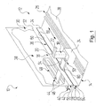
- FIG. 1 10 is a total of a device for treating objects, which includes a treatment room 12.
- the treatment room 12 belongs to a painting booth 14, in which objects are painted and of which only a section is shown.
- a treatment device 16 is arranged, which is formed in the present embodiment by a highly schematically illustrated, multi-axis painting robot 18, as it is known per se.
- the painting robot 18 comprises a robot arm 20, which at its free end carries an application device 22, which may be, for example, a spray gun or a rotary atomizer.
- the robotic arm 20 is disposed on a carriage 24 which can be moved on rails 26 in the treatment space 12 and for this purpose in a known manner drive components leads with you, which are not shown separately here.
- the treatment space 12 is bounded by walls, of which a bottom wall 28 and a vertical side wall 30 can be seen.
- the side wall 30 has a first, in the present embodiment, upper wall portion 32 and a second, in the present embodiment lower wall portion 34 which are separated by a horizontally extending gap 36.
- an outside area 38 outside the treatment room 12 of the spray booth 14 On the side remote from the treatment room 12 side of the side wall 30 is an outside area 38 outside the treatment room 12 of the spray booth 14, from which the painting robot 18 is supplied with resources such as electrical energy, fluid media and the like, the operation of the painting robot 18 and Painting the objects are necessary.
- supply lines are led to the painting robot 18, of which in the FIGS. 3, 4 and 5
- two electrical lines 40 and two fluid lines 42 are provided with reference numerals.
- the lines 40 and 42 are part of a generally designated 44 line bundle of Lackierroboters 18, which may not yet include specially designated additional supply lines.
- the cable bundle 44 extends from the outer region 38 through the gap 36 into the treatment chamber 12 and leads to the painting robot 18.
- the cable bundle 44 comprises in the present embodiment, a tube-like sheath 46, but it can also without such a sheath 46 through the individual lines 40, 42 and other components may be formed, as in the FIGS. 3 to 6 is recognizable.
- the lines 40, 42 are guided by means of a known and movable towing device 48 to the sheath 46.
- the wire bundle 44 can move along the gap 36 and follow the movement of the painting robot 18.
- the rails 26 in the treatment chamber 12 thereby give the painting robot 18 a movement path, on which the latter is moved between a first end position, which in FIG. 1 is shown, and a second end position, in FIG. 2 is shown, can move.
- the line bundle 44 forms a component 50 which extends from outside the treatment space 12 through the gap 36 into the treatment space 12 and is movable along the gap 36.
- a seal assembly 52 is provided which seals the gap 36 in the wall 30 of the treatment space 12 except for a through-hole 54 through which the wire bundle 44 extends and which follows a movement of the wire bundle 44 along the gap 36.
- the sealing arrangement 52 comprises a first sealing element 56 in the form of a first sealing strip 58, which extends at the upper wall section 32 along the gap 36 and has a coupling edge 60 remote from the upper wall section 32.
- the sealing arrangement 52 comprises a second sealing element 62 in the form of a second sealing strip 64, which extends on the second wall portion 34 along the gap 36 and has a second wall portion 34 remote from the coupling edge 66 which is complementary to the coupling edge 60 of the first sealing element 56.
- the line bundle 44 extends through the through opening 54 and the coupling edges 60 and 66 are coupled apart from the through hole 54 with each other.
- the coupling edges 60 and 66 couple in the direction of movement behind the wire bundle 44 with each other and separate in the direction of movement in front of the wire bundle 44 from each other.
- the direction of movement is only in FIG. 1 illustrated as a double arrow.
- a first sliding element 76 and a second sliding element 78 By means of a first sliding element 76 and a second sliding element 78, the coupling edges 66, 66 can be brought into engagement with each other or separated from one another depending on the direction of movement.
- the passage opening 54 for the cable bundle 44 remains between the two sliding elements 76 and 78th
- the seal assembly 52 includes a slider 80 which is disposed in the through hole 54 and receives the wire bundle 44.
- the slider 80 is connected in the direction of movement on both sides with the sliding elements 76 and 78 and has in the plane of the seal assembly 52 has a lenticular cross-section, so that the coupling edges 60, 66 at a movement of the slider 80 initially away from each other and then run towards each other again ,
- the slider 80 is integrally connected to the slide members 76 and 78.
- the slider 80 at its the coupling edges 60 and 66 that is, in the present embodiment
- the tooth rows 68 and 70, facing outer edges 82 each have a groove 84 in which the coupling edges 60, 66 are guided in a movement of the slider 80.
- Such a groove 84 may also be present if the sliding elements 76, 78 are not integrally connected to the sliding body 80.
- a supplemental sealing arrangement 52 is shown in which the rows of teeth 68 and 70 are protected in the treatment space 12 by a covering device 86.
- a cover strip 88, 90 is fastened to each sealing strip 58, 64, which extend respectively over the associated row of teeth 68 and are arranged and dimensioned in such a way that they overlap in the region of the mutually coupled rows of teeth 68, 70.
- the masking tapes 88, 90 may also have sealing properties in addition to the mechanical protective effect and thus additionally contribute to the overall tightness of the sealing arrangement 52.
- FIG. 8 is shown as a further embodiment, a seal assembly 52, in which the coupling edges 60 and 66 each have no row of teeth, but mutually complementary tear strips 92 and 94, which form a groove / spring system.
- the tear strips 92 and 94 are M-shaped in cross-section and thus each have a double groove 96 into which a double spring 98 of the respective other tear strip 92 or 94 can engage.
- the sliding members 76 and 78 fit correspondingly to the tear strips 92, 94.
- the seal arrangement 52 can also have two passage openings 54, through which in each case a line bundle 44 passes.
- FIG. 10 shows, alternatively, two seal assemblies 52 may be present, each with only one through hole 54, which in the in FIG. 10 shown embodiment are located at different height levels.
- the wall has two corresponding column 36.
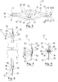
- FIG. 11 illustrates that with the aid of the seal assembly 52, a curve guidance of a component is possible, which extends from the outer region 38 through the gap 36 and the seal assembly 52 into the treatment chamber 12 inside.
- the gap 36 then runs in an arc, which the sealing elements 56 and 62 follow.
- FIG. 11 shown by a conveyor 100, in the schematically illustrated as a compact block drive components 102 are arranged in the outer region 38 and a support arm 104 extends through the gap 36 in the wall 30 and the seal assembly 52 into the treatment chamber 12 inside.
- the sliding body 80 receives this support arm 104 in the passage opening 54.
- the gap 36 can also run in a straight line.
- the support arm 104 At the end of the support arm 104, which is located in the treatment room 12, a not specifically shown fastening means for the objects to be conveyed is attached. With the aid of the conveyor 100, the objects can be conveyed through dip tanks in the treatment space 12 or past painting robots 18, for example.
- the support arm 104 is the component which extends through the through-hole 54 of the seal assembly 52 therethrough, which in turn follows a movement of the support arm 104 along the gap 36.
Landscapes
- Engineering & Computer Science (AREA)
- Mechanical Engineering (AREA)
- Robotics (AREA)
- General Engineering & Computer Science (AREA)
- Automobile Manufacture Line, Endless Track Vehicle, Trailer (AREA)
- Coating Apparatus (AREA)
- Furnace Details (AREA)
- Sealing Devices (AREA)
- Container, Conveyance, Adherence, Positioning, Of Wafer (AREA)
- Packages (AREA)
Description
- Die Erfindung betrifft eine Vorrichtung zum Behandeln von Gegenständen mit
- a) einem Behandlungsraum, bei welchem eine Wand mit einem ersten Wandabschnitt und einem zweiten Wandabschnitt vorhanden ist, zwischen denen ein in der Wand verlaufender Spalt ausgebildet ist;
- b) einer Einrichtung, insbesondere einer Behandlungseinrichtung oder einer Fördereinrichtung, welche wenigstens eine Komponente umfasst, die sich von einem Außenbereich au-ßerhalb des Behandlungsraumes durch den Spalt in den Behandlungsraum hinein erstreckt und entlang des Spaltes bewegbar ist;
- c) einer Dichtungsanordnung, welche den Spalt in der Wand des Behandlungsraumes abgesehen von wenigstens einer Durchgangsöffnung abdichtet, durch welche sich die wenigstens eine Komponente hindurch erstreckt und welche einer Bewegung der wenigstens einen Komponente entlang des Spaltes folgt;
wobei - d) die Dichtungsanordnung umfasst:
- da) ein erstes Dichtelement, welches sich am ersten Wandabschnitt entlang des Spaltes erstreckt und einen vom ersten Wandabschnitt abliegenden Koppelrand aufweist;
- db) ein zweites Dichtelement, welches sich am zweiten Wandabschnitt entlang des Spaltes erstreckt und einen vom zweiten Wandabschnitt abliegenden Koppelrand aufweist, der zum Koppelrand des ersten Dichtelements komplementär ist;
- e) die Dichtungsanordnung derart eingerichtet ist, dass
- ea) die Koppelränder abgesehen von der Durchgangsöffnung miteinander gekoppelt sind;
- eb) die Koppelränder sich beim Bewegen der wenigstens einen Komponente in deren Bewegungsrichtung vor der Durchgangsöffnung voneinander trennen und in Bewegungsrichtung hinter der Durchgangsöffnung miteinander koppeln.
- Eine solche Vorrichtung ist beispielsweise in der
DE 25 21 506 A1 beschrieben. - Für die industrielle Behandlung von Gegenständen, insbesondere von Fahrzeugkarosserien oder von deren Teilen, bei der große Stückzahlen umgesetzt werden müssen, kommen bevorzugt Vorrichtungen dieser Art zum Einsatz, bei denen die Gegenstände mit Hilfe einer Fördereinrichtung kontinuierlich oder diskontinuierlich durch den Behandlungsraum geführt werden. Solche Vorrichtungen haben eine hohe Kapazität und lassen sich gut in eine Fertigungslinie eingliedern. Eine Behandlung kann beispielsweise ein Lackieren oder auch ein Trocknen sein.
- Die Wände des Behandlungsraumes, worunter vorliegend sowohl Seitenwände als auch eine Bodenwand und eine Deckenwand verstanden werden sollen, trennen die Außenatmosphäre von der Innenatmosphäre des Behandlungsraumes und verhindern insbesondere ein Entweichen von gegebenenfalls appliziertem Behandlungsmedium und/oder von Wärme aus dem Behandlungsraum.
- Bei der Wand mit dem Spalt kann es sich um eine solche Wand des Behandlungsraumes handeln. Es kann aber auch eine Wand eines Gehäuses einer sonstigen Baugruppe sein, welche in dem Behandlungsraum angeordnet ist. Beispielsweise kann die Wand zu dem Gehäuse einer Abdeckung für eine Führungsbahn gehören, auf der ein Applikationsroboter verfahren wird. Das Gehäuse deckt dann zum Beispiel auch Antriebskomponenten dieses Roboters ab, um diese vor dem Einfluss der Atmosphäre des Behandlungsraumes zu schützen.
- Bei dem Behandlungsmedium kann es sich um eine Behandlungsflüssigkeit handeln, was beispielsweise beim Lackieren von Gegenständen oder bei Vorbereitungsprozessen für das Lackieren der Fall ist. Grundsätzlich können jedoch ohne weitere Maßnahmen auch Gase und Dämpfe aus dem Behandlungsraum entweichen, wie sie beispielsweise bei Trocknern oder Spritzkabinen vorhanden sein können. In Spritzkabinen sollen darüber hinaus z.B. auch Flüssigkeits- oder Pulvernebel von der Umgebung des Behandlungsraumes abgehalten werden.
- Durch die Wände des Behandlungsraumes soll außerdem auch verhindert werden, dass Schmutz von außen in den Behandlungsraum eindringt.
- Die Einrichtung, von der sich wenigstens eine Komponente durch den Spalt in der Wand in den Behandlungsraum erstreckt, kann beispielsweise eine Behandlungseinrichtung und in diesem Fall zum Beispiel ein mehrachsiger Applikationsroboter sein, wie es an und für sich bekannt ist. Ein solcher Roboter umfasst elektrische Leitungen und Fluidleitungen, die als Leitungsbündel von außen in den Behandlungsraum zum Roboterarm geführt werden und diesem bei einer Bewegung folgen. Der Roboterarm führt an dem Ende, das sich im Inneren des Behandlungsraumes befindet, eine Applikationseinrichtung, beispielsweise eine Spritzpistole oder einen Rotationszerstäuber.
- Gegebenenfalls kann auch der Roboterarm selbst diejenige Komponenten sein, die sich von außerhalb des Behandlungsraumes durch den Spalt in den Behandlungsraum hinein erstreckt, während auf der anderen Seite der Wand die Antriebskomponenten des Roboters, zum Beispiel unter anderem ein parallel zur Wand verfahrbarer Schlitten mit entsprechenden Motoren, angeordnet ist.
- Die Einrichtung, von der sich wenigstens eine Komponenten durch den Spalt in der Wand in den Behandlungsraum erstreckt, kann zum Beispiel auch eine Fördereinrichtung sein. Dabei wird besonders darauf geachtet, dass diejenigen Bauteile des Förderers, von denen möglicherweise Schmutzstoffe ausgehen können, insbesondere die Antriebskomponenten, au-ßerhalb des Behandlungsraumes angeordnet sind. Um die Gegenstände zu tragen, müssen in Betracht kommende Förderer einen Tragarm aufweisen, der die Wand des Behandlungsraumes durchdringt und an dessen im Behandlungsraum liegenden Ende die Gegenstände befestigt werden können. Hierfür ist der Spalt in der Wand des Behandlungsraumes vorhanden, der entlang des Bewegungsweges des Förderers verläuft und abgesehen von der gesonderten Dichtungsanordnung verschlossen wird. Bei einer solchen Fördereinrichtung ist dann also der Tragarm die oben definierte Komponente, die sich von außerhalb des Behandlungsraumes durch den Spalt in den Behandlungsraum hinein erstreckt und entlang des Spaltes bewegbar ist.
- Bei bekannten Vorrichtungen der eingangs genannten Art, bei welchen sich die Dichtungsanordnung entsprechend im Bereich des Tragarmes lokal öffnen kann, werden als Dichtungsanordnungen häufig elastische Dichtlippen verwendet, welche den Tragarm von zwei gegenüberliegenden Seiten umschließen und die dort, wo sich der Tragarm der Fördereinrichtung nicht befindet, an benachbarten Längsrändern lose aneinander anstoßen sollen.
- Die Verlässlichkeit solcher Dichtlippen ist jedoch nicht immer gewährleistet. Insbesondere kommt es vor, dass dort, wo sich der Tragarm nicht befindet, zwischen den Dichtlippen Zwischenräume verbleiben, durch welche unerwünschte Verunreinigungen in den Behandlungsraum hinein oder die Atmosphäre aus dem Behandlungsraum nach außen gelangen können.
- Eine andere derartige Behandlungsvorrichtung ist in der
DE 198 48 946 C2 beschrieben. Bei dieser umfasst die Dichtungsanordnung eine Mehrzahl von nebeneinander angeordneten, segmentartigen Dichtelementen, die sich in seitlicher Richtung überlappen und zur Passage eines Tragarmes einer Fördereinrichtung um Schenkachsen verschwenkt werden. Diese Lösung ist jedoch mechanisch sehr aufwendig. Aus derDE 192 49 243 B1 ist bekannt, stattdessen zur Abdichtung des Tragarmes einer Fördereinrichtung elastisch verbiegbare Federlamellen zu verwenden. Aber auch dort ist der bauliche Aufwand durch die Vielzahl an Einzelteilen recht hoch. - Unter dem Begriff dichten ist vorliegend nicht zwingend eine hermetische Abdichtung der benachbarten Bereiche zu verstehen. Ziel ist es, den Spalt bis auf eine akzeptable Restdurchlässigkeit abzudichten, die von Anlage zu Anlage unterschiedlichen ausfallen kann. Gegebenenfalls kann der Außenbereich mit einem Überdruck beaufschlagt sein, so dass ein Austreten von Atmosphäre des Behandlungsraums nach außen durch die Dichtungsanordnung erschwert ist.
- Aufgabe der vorliegenden Erfindung ist es, eine Vorrichtung der eingangs genannten Art so auszugestalten, dass der Spalt zwischen den beiden Abschnitten der Wand zuverlässig abgedichtet ist und die Dichtungsanordnung wartungsarm und zuverlässig ist.
- Diese Aufgabe wird bei einer Vorrichtung der eingangs genannten Art dadurch gelöst, dass
- f) die Dichtungsanordnung eine Abdeckeinrichtung umfasst, durch welche die Koppelränder im Behandlungsraum geschützt sind;
- g) die Abdeckeinrichtung an jedem Dichtelement ein Abdeckband umfasst, welche sich jeweils über den zugehörigen Koppelrand erstrecken und derart angeordnet und dimensioniert sind, dass sie im Bereich der miteinander gekoppelten Koppelränder überlappen.
- So werden mögliche belastende Einflüsse durch die Atmosphäre im Behandlungsraum gegen die Koppelränder zu verringert.
- Erfindungsgemäß werden folglich Dichtelemente verwendet, die anders als bei den oben erläuterten Dichtlippen in den Abschnitten, in denen sich die Durchgangsöffnung nicht befindet, miteinander verbunden sind. Hierdurch wird verhindert, dass sich dort unerwünschte Spalte bilden können, wie es bei lose aneinander anliegenden Dichtlippen der Fall sein kann.
- Vorzugsweise umfasst die Dichtungsanordnung ein erstes und ein zweites Schiebelement, mit deren Hilfe die Koppelränder abhängig von der Bewegungsrichtung in Eingriff ineinander gebracht oder voneinander getrennt werden können, wobei die Durchgangsöffnung zwischen den Schiebelementen verbleibt.
- Wenn die Koppelränder zueinander komplementäre Zahnreihen aufweisen, die abhängig von der Bewegungsrichtung in Eingriff ineinander bringbar oder voneinander trennbar sind, kann die Dichtungsanordnung vorteilhaft nach Art eines Reißverschlusses ausgebildet sein.
- Alternativ ist es günstig, wenn die Koppelränder zueinander komplementäre Reißstreifen aufweisen, die ein Nut/Federsystem bilden.
- Wenn die Reißstreifen dabei jeweils eine Doppelnut und eine Doppelfeder umfassen, ist in den Abschnitten, in denen die Koppelränder miteinander gekoppelt sind, eine hohe Dichtigkeit möglich.
- Eine sichere Führung der durch den Spalt tretenden Komponente ist gewährleistet, wenn die Dichtungsanordnung einen Gleitkörper umfasst, der in der Durchgangsöffnung angeordnet ist und die wenigstens eine Komponente der Einrichtung aufnimmt.
- Damit die Bewegung des Gleitkörpers und der Koppel- bzw. Entkoppelvorgang bei den Koppelrändern aufeinander abgestimmt erfolgen kann, ist es günstig, wenn der Gleitkörper in Bewegungsrichtung zu beiden Seiten mit den Schiebeelementen verbunden ist. Diese Verbindung kann auch einstückig sein; in diesem Fall sind die Schiebeelemente folglich in den Gleitkörper integriert.
- Vorteilhaft hat der Gleitkörper in der Ebene der Dichtungsanordnung einen linsenförmigen Querschnitt. Auf diese Weise werden die Koppelränder bei einer Bewegung des Gleitkörpers zunächst voneinander weg und dann wieder aufeinander zu geführt, wodurch die Durchgangsöffnung erzeugt wird, die in diesem Fall der Kontur des Gleitkörpers folgt.
- Vorzugsweise weist der Gleitkörper an seinen den Koppelrändern zugewandten Außenrändern jeweils eine Nut auf, in welcher die Koppelränder bei einer Bewegung des Gleitkörpers geführt sind. Auf diese Weise ist ein Ausbrechen der Koppelränder in eine zur Bewegungsrichtung senkrechte Richtung verhindert.
- Nachstehend werden Ausführungsbeispiele der Erfindung anhand der Zeichnungen näher erläutert. In diesen zeigen:
- Figur 1
- perspektivisch einen Ausschnitt einer Lackierkabine mit einer teilweise weggebrochenen Wand, wobei ein Leitungsbündel zur Versorgung eines Lackierroboters durch die Wand und eine Durchgangsöffnung einer Dichtungsanordnung geführt ist, der in der Lackierkabine verfahren werden kann und in einer ersten Endposition auf seinem Bewegungsweg gezeigt ist;
- Figur 2
- eine der
Figur 1 entsprechende perspektivische Ansicht der Lackierkabine mit dem Lackierroboter in seiner zweiten Endposition auf seinem Bewegungsweg; - Figur 3
- eine Draufsicht auf einen Ausschnitt der Dichtungsanordnung im Bereich der Durchgangsöffnung;
- Figur 4
- eine der
Figur 3 entsprechende Draufsicht auf einen Ausschnitt einer abgewandelten Dichtungsanordnung im Bereich der Durchgangsöffnung; - Figur 5
- eine der
Figur 3 entsprechende Draufsicht auf einen Ausschnitt einer nochmals abgewandelten Dichtungsanordnung im Bereich der Durchgangsöffnung; - Figur 6
- einen Schnitt der Dichtungsanordnung von
Figur 5 gemäß der dortigen Schnittlinie VI-VI in größerem Maßstab; - Figur 7
- einen Schnitt der Dichtungsanordnung von
Figur 5 gemäß der dortigen Schnittlinie VII-VII ebenfalls in größerem Maßstab; - Figur 8
- einen der
Figur 7 entsprechenden Schnitt einer nochmals abgewandelten Dichtungsanordnung; - Figur 9
- eine der
Figur 1 entsprechende perspektivische Ansicht der Lackierkabine mit einer Dichtungsanordnung, die für zwei oder mehr Lackierroboter ausgelegt ist, die in Längsrichtung der Lackierkabine hintereinander angeordnet bewegt werden können; - Figur 10
- eine der
Figur 9 entsprechende perspektivische Ansicht der Lackierkabine mit einer nochmals abgewandelten Dichtungsanordnung für zwei oder mehr Lackierroboter; - Figur 11
- eine der
Figur 1 ähnliche perspektivische Ansicht einer Lackierkabine, wobei stark vereinfacht eine mögliche Bogenfahrt am Beispiel einer Fördereinrichtung veranschaulicht ist. - In
Figur 1 ist mit 10 insgesamt eine Vorrichtung zum Behandeln von Gegenständen bezeichnet, welche einen Behandlungsraum 12 umfasst. Beim vorliegenden Ausführungsbeispiel gehört der Behandlungsraum 12 zu einer Lackierkabine 14, in welcher Gegenstände lackiert werden und von welcher lediglich ein Ausschnitt gezeigt ist. - In dem Behandlungsraum 12 ist eine Behandlungseinrichtung 16 angeordnet, die beim vorliegenden Ausführungsbeispiel durch einen stark schematisch dargestellten, mehrachsigen Lackierroboter 18 gebildet ist, wie er an und für sich bekannt ist. Der Lackierroboter 18 umfasst einen Roboterarm 20, der an seinem freien Ende eine Applikationseinrichtung 22 führt, bei der es sich beispielsweise um eine Spritzpistole oder einen Rotationszerstäuber handeln kann.
- Der Roboterarm 20 ist auf einem Schlitten 24 angeordnet, der auf Schienen 26 in dem Behandlungsraum 12 verfahren werden kann und zu diesem Zweck in bekannter Art und Weise Antriebskomponenten mit sich führt, die hier nicht gesondert gezeigt sind.
- Der Behandlungsraum 12 ist durch Wände begrenzt, von denen eine Bodenwand 28 und eine vertikale Seitenwand 30 zu erkennen sind. Die Seitenwand 30 hat einen ersten, beim vorliegenden Ausführungsbeispiel oberen Wandabschnitt 32 und einen zweiten, beim vorliegenden Ausführungsbeispiel unteren Wandabschnitt 34, die durch einen horizontal verlaufenden Spalt 36 voneinander getrennt sind.
- Auf der vom Behandlungsraum 12 abliegenden Seite der Seitenwand 30 befindet sich ein Außenbereich 38 außerhalb des Behandlungsraums 12 der Lackierkabine 14, von dem aus der Lackierroboter 18 mit Betriebsmitteln wie elektrischer Energie, fluiden Medien und dergleichen versorgt wird, die zum Betrieb des Lackierroboters 18 und zum Lackieren der Gegenstände notwendig sind. Hierfür werden Versorgungsleitungen zu dem Lackierroboter 18 geführt, von denen in den
Figuren 3, 4 und5 exemplarisch zwei elektrische Leitungen 40 und zwei Fluidleitungen 42 mit Bezugszeichen versehen sind. - Die Leitungen 40 und 42 sind Teil eines insgesamt mit 44 bezeichneten Leitungsbündels des Lackierroboters 18, welches auch noch nicht eigens bezeichnete weitere Versorgungsleitungen umfassen kann. Das Leitungsbündel 44 erstreckt sich von dem Außenbereich 38 durch den Spalt 36 in den Behandlungsraum 12 hinein und führt zu dem Lackierroboter 18. Das Leitungsbündel 44 umfasst beim vorliegenden Ausführungsbeispiel eine rohrähnliche Hülle 46, es kann jedoch auch ohne eine solche Hülle 46 durch die einzelnen Leitungen 40, 42 und weitere Bauteile gebildet sein, wie es in den
Figuren 3 bis 6 erkennbar ist. Im Außenbereich 38 werden die Leitungen 40, 42 mit Hilfe einer an und für sich bekannten und beweglichen Schleppeinrichtung 48 zu der Hülle 46 geführt. - Das Leitungsbündel 44 kann sich entlang des Spaltes 36 bewegen und der Bewegung des Lackierroboters 18 folgen. Die Schienen 26 im Behandlungsraum 12 geben dem Lackierroboter 18 dabei einen Bewegungsweg vor, auf dem sich dieser zwischen einer ersten Endposition, die in
Figur 1 gezeigt ist, und einer zweiten Endposition, die inFigur 2 gezeigt ist, bewegen kann. - Allgemein ausgedrückt bildet beim vorliegenden Ausführungsbeispiel das Leitungsbündel 44 eine Komponente 50, die sich von außerhalb des Behandlungsraumes 12 durch den Spalt 36 in den Behandlungsraum 12 hinein erstreckt und entlang des Spaltes 36 bewegbar ist.
- Wie eingangs erläutert, soll weitgehend verhindert werden, dass Atmosphäre aus dem Behandlungsraum 12 in den Außenbereich 38 oder aus diesem in den Behandlungsraum 12 gelangt. Aus diesem Grund ist eine Dichtungsanordnung 52 vorhanden, welche den Spalt 36 in der Wand 30 des Behandlungsraumes 12 abgesehen von einer Durchgangsöffnung 54 abdichtet, durch welche sich das Leitungsbündel 44 hindurch erstreckt und welche einer Bewegung des Leitungsbündels 44 entlang des Spaltes 36 folgt.
- Die Dichtungsanordnung 52 umfasst ein erstes Dichtelement 56 in Form eines ersten Dichtbandes 58, welches sich am oberen Wandabschnitt 32 entlang des Spaltes 36 erstreckt und einen vom oberen Wandabschnitt 32 abliegenden Koppelrand 60 aufweist. Außerdem umfasst die Dichtungsanordnung 52 ein zweites Dichtelement 62 in Form eines zweiten Dichtbandes 64, welches sich am zweiten Wandabschnitt 34 entlang des Spaltes 36 erstreckt und einen vom zweiten Wandabschnitt 34 abliegenden Koppelrand 66 aufweist, der zum Koppelrand 60 des ersten Dichtelements 56 komplementär ist.
- Das Leitungsbündel 44 erstreckt sich durch die Durchgangsöffnung 54 und die Koppelränder 60 und 66 sind abgesehen von der Durchgangsöffnung 54 miteinander gekoppelt. Wenn das Leitungsbündel 44 sich im Spalt 36 bewegt, koppeln die Koppelränder 60 und 66 in Bewegungsrichtung hinter dem Leitungsbündel 44 miteinander und trennen sich in Bewegungsrichtung vor dem Leitungsbündel 44 voneinander. Die Bewegungsrichtung ist nur in
Figur 1 als Doppelpfeil veranschaulicht. - Wie in
Figur 3 veranschaulicht, ist dies beim vorliegenden Ausführungsbeispiel dadurch ermöglicht, dass die Koppelränder 60, 66 nach Art eines Reißverschlusses zueinander komplementäre Zahnreihen 68 bzw. 70 mit Zähnen 72 bzw. 74 aufweisen. Mit Hilfe eines ersten Schiebeelements 76 und eines zweiten Schiebeelementes 78 können die Koppelränder 66, 66 abhängig von der Bewegungsrichtung in Eingriff ineinander gebracht oder voneinander getrennt werden. Die Durchgangsöffnung 54 für das Leitungsbündel 44 verbleibt dabei zwischen den beiden Schiebeelementen 76 und 78. - Außerdem umfasst die Dichtungsanordnung 52 einen Gleitkörper 80, der in der Durchgangsöffnung 54 angeordnet ist und das Leitungsbündel 44 aufnimmt. Der Gleitkörper 80 ist in Bewegungsrichtung zu beiden Seiten mit den Schiebeelementen 76 und 78 verbunden und hat in der Ebene der Dichtungsanordnung 52 einen linsenförmigen Querschnitt, so dass die Koppelränder 60, 66 bei einer Bewegung des Gleitkörpers 80 zunächst voneinander weg und dann wieder aufeinander zu laufen.
- Bei einer in
Figur 4 gezeigten Abwandlung ist der Gleitkörper 80 einstückig mit den Schiebelementen 76 und 78 verbunden. Außerdem weist der Gleitkörper 80 an seinen den Koppelrändern 60 und 66, d.h. beim vorliegenden Ausführungsbeispiel den Zahnreihen 68 und 70, zugewandten Außenrändern 82 jeweils eine Nut 84, in welcher die Koppelränder 60, 66 bei einer Bewegung des Gleitkörpers 80 geführt sind. Eine solche Nut 84 kann auch vorhanden sein, wenn die Schiebeelemente 76, 78 nicht einstückig mit dem Gleitkörper 80 verbunden sind. - In den
Figuren 5 bis 7 ist eine ergänzte Dichtanordnung 52 gezeigt, bei der die Zahnreihen 68 und 70 im Behandlungsraum 12 durch eine Abdeckeinrichtung 86 geschützt sind. Hierzu ist an jedem Dichtband 58, 64 ein Abdeckband 88, 90 befestigt, welche sich jeweils über die zugehörige Zahnreihe 68 bzw. erstrecken und derart angeordnet und dimensioniert sind, dass sie im Bereich der miteinander gekoppelten Zahnreihen 68, 70 überlappen. Dies ist in denFiguren 5 und 7 gut zu erkennen. Die Abdeckbänder 88, 90 können neben der mechanischen Schutzwirkung auch dichtende Eigenschaften haben und so zusätzlich zur Gesamtdichtigkeit der Dichtungsanordnung 52 beitragen. - In
Figur 8 ist als weiteres Ausführungsbeispiel eine Dichtungsanordnung 52 gezeigt, bei welcher die Koppelränder 60 und 66 jeweils keine Zahnreihe, sondern zueinander komplementäre Reißstreifen 92 und 94 haben, die ein Nut/Federsystem bilden. Die Reißstreifen 92 und 94 sind im Querschnitt M-förmig und haben so jeweils eine Doppelnut 96, in welche eine Doppelfeder 98 des jeweils anderen Reißstreifens 92 bzw. 94 eingreifen kann. Die Schiebeelement 76 und 78 passen entsprechend zu den Reißstreifen 92, 94. - Bei den nachfolgend erläuterten
Figuren 9 ,10 und11 sind der Einfachheit halber nicht alle oben erläuterten Komponenten mit einem Bezugszeichen versehen. - Wie in
Figur 9 zu erkennen ist, können auch Lackierroboter 18, d.h. also zwei Behandlungseinrichtungen 16, in dem Behandlungsraum 12 angeordnet sein. In diesem Fall kann die Dichtungsanordnung 52 auch zwei Durchgangsöffnungen 54 aufweisen, durch welche jeweils ein Leitungsbündel 44 hindurchtritt. - Wie
Figur 10 zeigt, können alternativ auch zwei Dichtungsanordnungen 52 mit jeweils nur einer Durchgangsöffnung 54 vorhanden sein, die beim inFigur 10 gezeigten Ausführungsbeispiel auf unterschiedlichen Höhenniveaus angesiedelt sind. Dort hat die Wand entsprechend zwei Spalte 36. - In
Figur 11 ist veranschaulicht, dass mit Hilfe der Dichtungsanordnung 52 auch eine Kurvenführung einer Komponente möglich ist, die sich von dem Außenbereich 38 durch den Spalt 36 und die Dichtungsanordnung 52 in den Behandlungsraum 12 hinein erstreckt. Der Spalt 36 verläuft dann in einem Bogen, dem die Dichtelemente 56 und 62 folgen. - Dies ist in
Figur 11 anhand einer Fördereinrichtung 100 gezeigt, bei der schematisch als kompakter Block veranschaulichte Antriebskomponenten 102 im Außenbereich 38 angeordnet sind und sich ein Tragarm 104 durch den Spalt 36 in der Wand 30 und die Dichtungsanordnung 52 hindurch in den Behandlungsraum 12 hinein erstreckt. Der Gleitkörper 80 nimmt diesen Tragarm 104 in der Durchgangsöffnung 54 auf. Bei einer Fördereinrichtung 100 kann der Spalt 36 natürlich auch geradlinig verlaufen. - Am Ende des Tragarmes 104, das sich im Behandlungsraum 12 befindet, ist eine nicht eigens gezeigte Befestigungseinrichtung für die zu fördernden Gegenstände angebracht. Mit Hilfe der Fördereinrichtung 100 können die Gegenstände beispielsweise durch Tauchbecken im Behandlungsraum 12 hindurch oder an Lackierrobotern 18 vorbei gefördert werden. Bei einer derartigen Fördereinrichtung 100 ist der Tragarm 104 diejenige Komponente, die sich durch die Durchgangsöffnung 54 der Dichtungsanordnung 52 hindurch erstreckt, die ihrerseits einer Bewegung des Tragarmes 104 entlang des Spaltes 36 folgt.
Claims (9)
- Vorrichtung zum Behandeln von Gegenständen mita) einem Behandlungsraum (12), bei welchem eine Wand (30) mit einem ersten Wandabschnitt (32) und einem zweiten Wandabschnitt (34) vorhanden ist, zwischen denen ein in der Wand (30) verlaufender Spalt (36) ausgebildet ist;b) einer Einrichtung (16; 100), insbesondere einer Behandlungseinrichtung (16) oder einer Fördereinrichtung (100), welche wenigstens eine Komponente (44; 104) umfasst, die sich von einem Außenbereich (38) außerhalb des Behandlungsraumes (12) durch den Spalt (36) in den Behandlungsraum (12) hinein erstreckt und entlang des Spaltes (36) bewegbar ist;c) einer Dichtungsanordnung (52), welche den Spalt (36) in der Wand (30) des Behandlungsraumes (12) abgesehen von wenigstens einer Durchgangsöffnung (54) abdichtet, durch welche sich die wenigstens eine Komponente (44; 104) hindurch erstreckt und welche einer Bewegung der wenigstens einen Komponente (44; 104) entlang des Spaltes (36) folgt,
wobeid) die Dichtungsanordnung (52) umfasst:da) ein erstes Dichtelement (56), welches sich am ersten Wandabschnitt (32) entlang des Spaltes (36) erstreckt und einen vom ersten Wandabschnitt (32) abliegenden Koppelrand (60) aufweist;db) ein zweites Dichtelement (62), welches sich am zweiten Wandabschnitt (34) entlang des Spaltes (36) erstreckt und einen vom zweiten Wandabschnitt (34) abliegenden Koppelrand (66) aufweist, der zum Koppelrand (60) des ersten Dichtelements (56) komplementär ist;e) die Dichtungsanordnung (52) derart eingerichtet ist, dassea) die Koppelränder (60, 66) abgesehen von der Durchgangsöffnung (54) miteinander gekoppelt sind;eb) die Koppelränder (60, 66) sich beim Bewegen der wenigstens einen Komponente (44; 104) in deren Bewegungsrichtung vor der Durchgangsöffnung (54) voneinander trennen und in Bewegungsrichtung hinter der Durchgangsöffnung (54) miteinander koppeln,dadurch gekennzeichnet, dassf) die Dichtungsanordnung (52) eine Abdeckeinrichtung (86) umfasst, durch welche die Koppelränder (60, 66) im Behandlungsraum (12) geschützt sind.g) die Abdeckeinrichtung (86) an jedem Dichtelement (56, 62) ein Abdeckband (88, 90) umfasst, welche sich jeweils über den zugehörigen Koppelrand (60, 66) erstrecken und derart angeordnet und dimensioniert sind, dass sie im Bereich der miteinander gekoppelten Koppelränder (60, 66) überlappen. - Vorrichtung nach einem der Ansprüche 1, dadurch gekennzeichnet, dass die Dichtungsanordnung (52) ein erstes und ein zweites Schiebelement (76, 78) umfasst, mit deren Hilfe die Koppelränder (60, 66) abhängig von der Bewegungsrichtung in Eingriff ineinander gebracht oder voneinander getrennt werden können, wobei die Durchgangsöffnung (54) zwischen den Schiebelementen (76, 78) verbleibt.
- Vorrichtung nach Anspruch 1 oder 2, dadurch gekennzeichnet, dass die Koppelränder (60, 66) zueinander komplementäre Zahnreihen (68, 70) aufweisen, die abhängig von der Bewegungsrichtung in Eingriff ineinander bringbar oder voneinander trennbar sind.
- Vorrichtung nach Anspruch 1 oder 2, dadurch gekennzeichnet, dass die Koppelränder (60, 66) zueinander komplementäre Reißstreifen (92, 94) aufweisen, die ein Nut/ Federsystem bilden.
- Vorrichtung nach Anspruch 4, dadurch gekennzeichnet, dass die Reißstreifen (92, 94) jeweils eine Doppelnut (96) und eine Doppelfeder (98) umfassen.
- Vorrichtung nach einem der Ansprüche 1 bis 5, dadurch gekennzeichnet, dass die Dichtungsanordnung (52) einen Gleitkörper (80) umfasst, der in der Durchgangsöffnung (54) angeordnet ist und die wenigstens eine Komponente (44; 104) der Einrichtung (16; 100) aufnimmt.
- Vorrichtung nach Anspruch 6 unter Rückbezug auf Anspruch 2, dadurch gekennzeichnet, dass der Gleitkörper (80) in Bewegungsrichtung zu beiden Seiten mit den Schiebeelementen (76, 78) verbunden ist.
- Vorrichtung nach Anspruch 7, dadurch gekennzeichnet, dass der Gleitkörper (80) in der Ebene der Dichtungsanordnung (52) einen linsenförmigen Querschnitt hat.
- Vorrichtung nach einem der Ansprüche 6 bis 8, dadurch gekennzeichnet, dass der Gleitkörper (80) an seinen den Koppelrändern (60, 66) zugewandten Außenrändern (82) jeweils eine Nut (84) aufweist, in welcher die Koppelränder (60, 66) bei einer Bewegung des Gleitkörpers (80) geführt sind.
Applications Claiming Priority (2)
| Application Number | Priority Date | Filing Date | Title |
|---|---|---|---|
| DE102013019231.5A DE102013019231A1 (de) | 2013-11-16 | 2013-11-16 | Vorrichtung zum Behandeln von Gegenständen |
| PCT/EP2014/003059 WO2015070988A2 (de) | 2013-11-16 | 2014-11-14 | Vorrichtung zum behandeln von gegenständen |
Publications (2)
| Publication Number | Publication Date |
|---|---|
| EP3071336A2 EP3071336A2 (de) | 2016-09-28 |
| EP3071336B1 true EP3071336B1 (de) | 2019-07-10 |
Family
ID=52013994
Family Applications (1)
| Application Number | Title | Priority Date | Filing Date |
|---|---|---|---|
| EP14808831.3A Active EP3071336B1 (de) | 2013-11-16 | 2014-11-14 | Dichtungsanordnung für einen behandlungsraum |
Country Status (5)
| Country | Link |
|---|---|
| US (1) | US9956574B2 (de) |
| EP (1) | EP3071336B1 (de) |
| CN (1) | CN105722605B (de) |
| DE (1) | DE102013019231A1 (de) |
| WO (1) | WO2015070988A2 (de) |
Families Citing this family (8)
| Publication number | Priority date | Publication date | Assignee | Title |
|---|---|---|---|---|
| DE102015213008A1 (de) * | 2015-07-10 | 2017-01-12 | Eos Gmbh Electro Optical Systems | Vorrichtung und Verfahren zum Herstellen eines dreidimensionalen Objekts |
| CN107243439B (zh) * | 2017-06-13 | 2018-06-12 | 江苏泓睿德智能科技有限公司 | 一种led点胶封装设备 |
| CN108284015B (zh) * | 2018-03-09 | 2024-01-23 | 上海发那科机器人有限公司 | 一种高防护喷涂轨道 |
| DE102018213499B4 (de) * | 2018-08-10 | 2021-07-08 | Kuka Deutschland Gmbh | Roboterarm mit über wenigstens ein linienförmiges Verbindungselement verbundenen Gehäuseschalen |
| CN109365201B (zh) * | 2018-11-06 | 2024-02-23 | 裕东(中山)机械工程有限公司 | 一种自动枪汇集梁进出槽口采用动密封结构的喷粉室 |
| CN110152931B (zh) * | 2019-06-17 | 2020-10-20 | 安徽宁隆机械科技有限公司 | 一种精铸摆臂表面喷涂装置 |
| CN111299035A (zh) * | 2020-02-20 | 2020-06-19 | 上海航天精密机械研究所 | 瓜瓣类零件表面化学铣切保护胶自动喷涂方法及装置 |
| US11614160B1 (en) * | 2022-03-15 | 2023-03-28 | Honda Motor Co., Ltd. | Shift gate assembly for vehicle including gate seal and method of using same |
Citations (3)
| Publication number | Priority date | Publication date | Assignee | Title |
|---|---|---|---|---|
| DE1883255U (de) * | 1961-11-11 | 1963-11-21 | Hensoldt & Soehne Optische Wer | Schutzvorrichtung fuer massstaebe an werkzeugmaschinen. |
| FR2301197A1 (fr) * | 1975-02-21 | 1976-09-17 | Yoshida Kogyo Kk | Fermeture a glissiere |
| DE2521506A1 (de) * | 1975-03-20 | 1976-10-07 | Paul Thome | Dichte, bewegliche durchfuehrung |
Family Cites Families (21)
| Publication number | Priority date | Publication date | Assignee | Title |
|---|---|---|---|---|
| US3473404A (en) * | 1968-04-23 | 1969-10-21 | Sherwood B Ross | Operating-lever console for a gearshift mechanism or the like |
| US4089270A (en) * | 1976-09-17 | 1978-05-16 | Dahlberg Industries | Personal transporation system |
| DE3023044C2 (de) * | 1980-06-20 | 1982-03-25 | Otto Müller GmbH, 7012 Fellbach | Kabine zur Oberflächenbeschichtung von Gegenständen |
| GB2094395B (en) * | 1981-03-06 | 1985-03-13 | Mitutoyo Mfg Co Ltd | Dust excluding fasteners |
| DE3201058C2 (de) | 1982-01-15 | 1985-08-29 | Reinhard 7310 Plochingen Lipinski | Schutzabdeckung für eine Welle oder Spindel |
| US4689757A (en) * | 1983-01-17 | 1987-08-25 | Vada Systems, Inc. | Machine event processing system |
| DE3636416C1 (en) * | 1986-10-25 | 1988-02-04 | Duerr Gmbh & Co | Sealing apparatus for an overhead conveyor |
| JPH0661375B2 (ja) * | 1986-11-05 | 1994-08-17 | 富市 福田 | ゴルフカ−ト |
| US4964359A (en) * | 1988-12-22 | 1990-10-23 | Emhart Industries, Inc. | Automotive gearshift indicator |
| JPH0721127Y2 (ja) * | 1989-06-22 | 1995-05-17 | ワイケイケイ株式会社 | スライドファスナーの封鎖装置 |
| EP0832829B1 (de) * | 1996-09-23 | 2002-05-02 | Jervis B. Webb International Company | Abdeckung für Förderbahn |
| DE19848946C2 (de) | 1998-10-23 | 2000-08-10 | Eisenmann Kg Maschbau | Pendelförderer |
| US6341565B1 (en) * | 1999-11-15 | 2002-01-29 | Noble Drilling Corporation | Pipe racking system track cover |
| WO2001053000A2 (de) * | 2000-01-21 | 2001-07-26 | Gerd Wurster | Pulverbeschichtungsanlage und beschichtungsverfahren |
| US6615952B2 (en) * | 2000-03-02 | 2003-09-09 | Kabushiki Kaisha Toshiba | Double deck elevator |
| AT411650B (de) * | 2002-01-09 | 2004-04-26 | Koerner Chemieanlagen | Verdrängungskörper |
| DE50212060D1 (de) | 2002-01-23 | 2008-05-21 | Eisenmann Anlagenbau Gmbh & Co | Vorrichtung zur Behandlung von Werkstücken |
| DE10249243B4 (de) * | 2002-01-23 | 2005-06-23 | Eisenmann Maschinenbau Gmbh & Co. Kg | Vorrichtung zur Behandlung von Werkstücken |
| US6928703B2 (en) * | 2002-03-25 | 2005-08-16 | Robin Petravic | Sealed slider adjustment mechanism |
| US6499408B1 (en) * | 2002-04-02 | 2002-12-31 | Robert Kundel, Sr. | Rail support assembly for monorail crane |
| US9004496B2 (en) * | 2011-03-08 | 2015-04-14 | Felton, Inc. | Molded gap seal apparatus with inward pointing fibrillations |
-
2013
- 2013-11-16 DE DE102013019231.5A patent/DE102013019231A1/de not_active Withdrawn
-
2014
- 2014-11-14 US US15/036,866 patent/US9956574B2/en active Active
- 2014-11-14 CN CN201480062397.5A patent/CN105722605B/zh active Active
- 2014-11-14 EP EP14808831.3A patent/EP3071336B1/de active Active
- 2014-11-14 WO PCT/EP2014/003059 patent/WO2015070988A2/de active Application Filing
Patent Citations (3)
| Publication number | Priority date | Publication date | Assignee | Title |
|---|---|---|---|---|
| DE1883255U (de) * | 1961-11-11 | 1963-11-21 | Hensoldt & Soehne Optische Wer | Schutzvorrichtung fuer massstaebe an werkzeugmaschinen. |
| FR2301197A1 (fr) * | 1975-02-21 | 1976-09-17 | Yoshida Kogyo Kk | Fermeture a glissiere |
| DE2521506A1 (de) * | 1975-03-20 | 1976-10-07 | Paul Thome | Dichte, bewegliche durchfuehrung |
Also Published As
| Publication number | Publication date |
|---|---|
| CN105722605A (zh) | 2016-06-29 |
| US9956574B2 (en) | 2018-05-01 |
| EP3071336A2 (de) | 2016-09-28 |
| WO2015070988A2 (de) | 2015-05-21 |
| WO2015070988A3 (de) | 2015-07-09 |
| US20160325303A1 (en) | 2016-11-10 |
| CN105722605B (zh) | 2018-12-28 |
| DE102013019231A1 (de) | 2015-05-21 |
Similar Documents
| Publication | Publication Date | Title |
|---|---|---|
| EP3071336B1 (de) | Dichtungsanordnung für einen behandlungsraum | |
| EP3186013B1 (de) | Vorrichtung zum behandeln von gegenständen | |
| EP1609532A1 (de) | Lackieranlage und zugehöriges Betriebsverfahren | |
| EP3715230A1 (de) | Behandlungsanlage zum behandeln von werkstücken | |
| DE102014211397B4 (de) | Roboter zur Handhabung von Transportgütern und Reinigungseinrichtung hierfür sowie Betriebsverfahren zum Betrieb eines Roboters | |
| EP1784901B2 (de) | Vorrichtung zum beschichten, insbesondere zum lackieren, von gegenständen, insbesondere von fahrzeugkarosserien | |
| DE3601437C2 (de) | Elektrischer Roboter zur Verwendung in Gefahrenzonen | |
| EP2791008B1 (de) | Beschichtungsanlage und entsprechendes betriebsverfahren | |
| EP1784288B1 (de) | Vorrichtung zum beschichten, insbesondere zum lackieren, von gegenständen, insbesondere von fahrzeugkarosserien | |
| EP2427279A2 (de) | Reinigungsanlage für kraftfahrzeugkarosseriebauteile | |
| DE1575424A1 (de) | Vorrichtung zum Verhindern der Ablagerung von Staub auf den Fuehrungsschienen einer Praezisionsapparatur | |
| DE102016003916A1 (de) | Lackierstation und zugehöriges Betriebsverfahren | |
| DE102004030858B3 (de) | Beschichtungsanlage und zugehöriges Betriebsverfahren | |
| DE3023044C2 (de) | Kabine zur Oberflächenbeschichtung von Gegenständen | |
| DE3637580C1 (de) | Vorrichtung zum Absaugen von Fasermaterial | |
| DE19749184B4 (de) | Lötvorrichtung | |
| DE10119906A1 (de) | Farbspritzanlage | |
| DE3634386C2 (de) | ||
| EP1277521A2 (de) | Beschichtungsanlage mit einem Abdeckband für eine Gehäuseöffnung | |
| AT411650B (de) | Verdrängungskörper | |
| EP3003584B1 (de) | Portalvorrichtung zur abschirmung des innenraums eines anlagengehäuses | |
| DE2220191C2 (de) | Einrichtung zur Entstaubung größerer Räume mit starkem Staubanfall | |
| DE10249243A1 (de) | Vorrichtung zur Behandlung von Werkstücken | |
| DE102004027101A1 (de) | Wasserabweisende luftdurchlässige Paneel-Vorrichtung | |
| AT501735B1 (de) | Vorrichtung mit einem relativ zu einem standgehäuse beweglichen werkzeughalter und mit einer am werkzeughalter und am standgehäuse angeschlossenen leitungsführung |
Legal Events
| Date | Code | Title | Description |
|---|---|---|---|
| PUAI | Public reference made under article 153(3) epc to a published international application that has entered the european phase |
Free format text: ORIGINAL CODE: 0009012 |
|
| 17P | Request for examination filed |
Effective date: 20160503 |
|
| AK | Designated contracting states |
Kind code of ref document: A2 Designated state(s): AL AT BE BG CH CY CZ DE DK EE ES FI FR GB GR HR HU IE IS IT LI LT LU LV MC MK MT NL NO PL PT RO RS SE SI SK SM TR |
|
| AX | Request for extension of the european patent |
Extension state: BA ME |
|
| DAX | Request for extension of the european patent (deleted) | ||
| STAA | Information on the status of an ep patent application or granted ep patent |
Free format text: STATUS: EXAMINATION IS IN PROGRESS |
|
| 17Q | First examination report despatched |
Effective date: 20170608 |
|
| REG | Reference to a national code |
Ref country code: DE Ref legal event code: R079 Ref document number: 502014012202 Country of ref document: DE Free format text: PREVIOUS MAIN CLASS: B05B0015120000 Ipc: B05B0013040000 |
|
| RIC1 | Information provided on ipc code assigned before grant |
Ipc: B05B 12/32 20180101ALI20181221BHEP Ipc: B25J 19/00 20060101ALI20181221BHEP Ipc: B25J 11/00 20060101ALI20181221BHEP Ipc: B05B 13/04 20060101AFI20181221BHEP Ipc: F16P 1/02 20060101ALI20181221BHEP Ipc: B25J 21/00 20060101ALI20181221BHEP Ipc: B05B 16/40 20180101ALI20181221BHEP Ipc: B05B 12/16 20180101ALI20181221BHEP Ipc: B05B 16/00 20180101ALI20181221BHEP |
|
| GRAP | Despatch of communication of intention to grant a patent |
Free format text: ORIGINAL CODE: EPIDOSNIGR1 |
|
| STAA | Information on the status of an ep patent application or granted ep patent |
Free format text: STATUS: GRANT OF PATENT IS INTENDED |
|
| INTG | Intention to grant announced |
Effective date: 20190201 |
|
| GRAS | Grant fee paid |
Free format text: ORIGINAL CODE: EPIDOSNIGR3 |
|
| GRAA | (expected) grant |
Free format text: ORIGINAL CODE: 0009210 |
|
| STAA | Information on the status of an ep patent application or granted ep patent |
Free format text: STATUS: THE PATENT HAS BEEN GRANTED |
|
| AK | Designated contracting states |
Kind code of ref document: B1 Designated state(s): AL AT BE BG CH CY CZ DE DK EE ES FI FR GB GR HR HU IE IS IT LI LT LU LV MC MK MT NL NO PL PT RO RS SE SI SK SM TR |
|
| REG | Reference to a national code |
Ref country code: GB Ref legal event code: FG4D Free format text: NOT ENGLISH |
|
| REG | Reference to a national code |
Ref country code: CH Ref legal event code: EP Ref country code: AT Ref legal event code: REF Ref document number: 1152961 Country of ref document: AT Kind code of ref document: T Effective date: 20190715 |
|
| REG | Reference to a national code |
Ref country code: DE Ref legal event code: R096 Ref document number: 502014012202 Country of ref document: DE |
|
| REG | Reference to a national code |
Ref country code: IE Ref legal event code: FG4D Free format text: LANGUAGE OF EP DOCUMENT: GERMAN |
|
| REG | Reference to a national code |
Ref country code: NL Ref legal event code: MP Effective date: 20190710 |
|
| REG | Reference to a national code |
Ref country code: LT Ref legal event code: MG4D |
|
| PG25 | Lapsed in a contracting state [announced via postgrant information from national office to epo] |
Ref country code: BG Free format text: LAPSE BECAUSE OF FAILURE TO SUBMIT A TRANSLATION OF THE DESCRIPTION OR TO PAY THE FEE WITHIN THE PRESCRIBED TIME-LIMIT Effective date: 20191010 Ref country code: NO Free format text: LAPSE BECAUSE OF FAILURE TO SUBMIT A TRANSLATION OF THE DESCRIPTION OR TO PAY THE FEE WITHIN THE PRESCRIBED TIME-LIMIT Effective date: 20191010 Ref country code: FI Free format text: LAPSE BECAUSE OF FAILURE TO SUBMIT A TRANSLATION OF THE DESCRIPTION OR TO PAY THE FEE WITHIN THE PRESCRIBED TIME-LIMIT Effective date: 20190710 Ref country code: LT Free format text: LAPSE BECAUSE OF FAILURE TO SUBMIT A TRANSLATION OF THE DESCRIPTION OR TO PAY THE FEE WITHIN THE PRESCRIBED TIME-LIMIT Effective date: 20190710 Ref country code: PT Free format text: LAPSE BECAUSE OF FAILURE TO SUBMIT A TRANSLATION OF THE DESCRIPTION OR TO PAY THE FEE WITHIN THE PRESCRIBED TIME-LIMIT Effective date: 20191111 Ref country code: NL Free format text: LAPSE BECAUSE OF FAILURE TO SUBMIT A TRANSLATION OF THE DESCRIPTION OR TO PAY THE FEE WITHIN THE PRESCRIBED TIME-LIMIT Effective date: 20190710 Ref country code: SE Free format text: LAPSE BECAUSE OF FAILURE TO SUBMIT A TRANSLATION OF THE DESCRIPTION OR TO PAY THE FEE WITHIN THE PRESCRIBED TIME-LIMIT Effective date: 20190710 Ref country code: HR Free format text: LAPSE BECAUSE OF FAILURE TO SUBMIT A TRANSLATION OF THE DESCRIPTION OR TO PAY THE FEE WITHIN THE PRESCRIBED TIME-LIMIT Effective date: 20190710 |
|
| PG25 | Lapsed in a contracting state [announced via postgrant information from national office to epo] |
Ref country code: AL Free format text: LAPSE BECAUSE OF FAILURE TO SUBMIT A TRANSLATION OF THE DESCRIPTION OR TO PAY THE FEE WITHIN THE PRESCRIBED TIME-LIMIT Effective date: 20190710 Ref country code: LV Free format text: LAPSE BECAUSE OF FAILURE TO SUBMIT A TRANSLATION OF THE DESCRIPTION OR TO PAY THE FEE WITHIN THE PRESCRIBED TIME-LIMIT Effective date: 20190710 Ref country code: RS Free format text: LAPSE BECAUSE OF FAILURE TO SUBMIT A TRANSLATION OF THE DESCRIPTION OR TO PAY THE FEE WITHIN THE PRESCRIBED TIME-LIMIT Effective date: 20190710 Ref country code: GR Free format text: LAPSE BECAUSE OF FAILURE TO SUBMIT A TRANSLATION OF THE DESCRIPTION OR TO PAY THE FEE WITHIN THE PRESCRIBED TIME-LIMIT Effective date: 20191011 Ref country code: IS Free format text: LAPSE BECAUSE OF FAILURE TO SUBMIT A TRANSLATION OF THE DESCRIPTION OR TO PAY THE FEE WITHIN THE PRESCRIBED TIME-LIMIT Effective date: 20191110 Ref country code: ES Free format text: LAPSE BECAUSE OF FAILURE TO SUBMIT A TRANSLATION OF THE DESCRIPTION OR TO PAY THE FEE WITHIN THE PRESCRIBED TIME-LIMIT Effective date: 20190710 |
|
| PG25 | Lapsed in a contracting state [announced via postgrant information from national office to epo] |
Ref country code: TR Free format text: LAPSE BECAUSE OF FAILURE TO SUBMIT A TRANSLATION OF THE DESCRIPTION OR TO PAY THE FEE WITHIN THE PRESCRIBED TIME-LIMIT Effective date: 20190710 |
|
| PG25 | Lapsed in a contracting state [announced via postgrant information from national office to epo] |
Ref country code: DK Free format text: LAPSE BECAUSE OF FAILURE TO SUBMIT A TRANSLATION OF THE DESCRIPTION OR TO PAY THE FEE WITHIN THE PRESCRIBED TIME-LIMIT Effective date: 20190710 Ref country code: EE Free format text: LAPSE BECAUSE OF FAILURE TO SUBMIT A TRANSLATION OF THE DESCRIPTION OR TO PAY THE FEE WITHIN THE PRESCRIBED TIME-LIMIT Effective date: 20190710 Ref country code: PL Free format text: LAPSE BECAUSE OF FAILURE TO SUBMIT A TRANSLATION OF THE DESCRIPTION OR TO PAY THE FEE WITHIN THE PRESCRIBED TIME-LIMIT Effective date: 20190710 Ref country code: RO Free format text: LAPSE BECAUSE OF FAILURE TO SUBMIT A TRANSLATION OF THE DESCRIPTION OR TO PAY THE FEE WITHIN THE PRESCRIBED TIME-LIMIT Effective date: 20190710 |
|
| PG25 | Lapsed in a contracting state [announced via postgrant information from national office to epo] |
Ref country code: CZ Free format text: LAPSE BECAUSE OF FAILURE TO SUBMIT A TRANSLATION OF THE DESCRIPTION OR TO PAY THE FEE WITHIN THE PRESCRIBED TIME-LIMIT Effective date: 20190710 Ref country code: SM Free format text: LAPSE BECAUSE OF FAILURE TO SUBMIT A TRANSLATION OF THE DESCRIPTION OR TO PAY THE FEE WITHIN THE PRESCRIBED TIME-LIMIT Effective date: 20190710 Ref country code: SK Free format text: LAPSE BECAUSE OF FAILURE TO SUBMIT A TRANSLATION OF THE DESCRIPTION OR TO PAY THE FEE WITHIN THE PRESCRIBED TIME-LIMIT Effective date: 20190710 Ref country code: IS Free format text: LAPSE BECAUSE OF FAILURE TO SUBMIT A TRANSLATION OF THE DESCRIPTION OR TO PAY THE FEE WITHIN THE PRESCRIBED TIME-LIMIT Effective date: 20200224 |
|
| REG | Reference to a national code |
Ref country code: DE Ref legal event code: R097 Ref document number: 502014012202 Country of ref document: DE |
|
| REG | Reference to a national code |
Ref country code: CH Ref legal event code: PL |
|
| PLBE | No opposition filed within time limit |
Free format text: ORIGINAL CODE: 0009261 |
|
| STAA | Information on the status of an ep patent application or granted ep patent |
Free format text: STATUS: NO OPPOSITION FILED WITHIN TIME LIMIT |
|
| PG2D | Information on lapse in contracting state deleted |
Ref country code: IS |
|
| PG25 | Lapsed in a contracting state [announced via postgrant information from national office to epo] |
Ref country code: LI Free format text: LAPSE BECAUSE OF NON-PAYMENT OF DUE FEES Effective date: 20191130 Ref country code: CH Free format text: LAPSE BECAUSE OF NON-PAYMENT OF DUE FEES Effective date: 20191130 Ref country code: LU Free format text: LAPSE BECAUSE OF NON-PAYMENT OF DUE FEES Effective date: 20191114 Ref country code: MC Free format text: LAPSE BECAUSE OF FAILURE TO SUBMIT A TRANSLATION OF THE DESCRIPTION OR TO PAY THE FEE WITHIN THE PRESCRIBED TIME-LIMIT Effective date: 20190710 |
|
| 26N | No opposition filed |
Effective date: 20200603 |
|
| REG | Reference to a national code |
Ref country code: BE Ref legal event code: MM Effective date: 20191130 |
|
| PG25 | Lapsed in a contracting state [announced via postgrant information from national office to epo] |
Ref country code: SI Free format text: LAPSE BECAUSE OF FAILURE TO SUBMIT A TRANSLATION OF THE DESCRIPTION OR TO PAY THE FEE WITHIN THE PRESCRIBED TIME-LIMIT Effective date: 20190710 |
|
| GBPC | Gb: european patent ceased through non-payment of renewal fee |
Effective date: 20191114 |
|
| PG25 | Lapsed in a contracting state [announced via postgrant information from national office to epo] |
Ref country code: GB Free format text: LAPSE BECAUSE OF NON-PAYMENT OF DUE FEES Effective date: 20191114 Ref country code: IE Free format text: LAPSE BECAUSE OF NON-PAYMENT OF DUE FEES Effective date: 20191114 |
|
| PG25 | Lapsed in a contracting state [announced via postgrant information from national office to epo] |
Ref country code: BE Free format text: LAPSE BECAUSE OF NON-PAYMENT OF DUE FEES Effective date: 20191130 |
|
| REG | Reference to a national code |
Ref country code: AT Ref legal event code: MM01 Ref document number: 1152961 Country of ref document: AT Kind code of ref document: T Effective date: 20191114 |
|
| PG25 | Lapsed in a contracting state [announced via postgrant information from national office to epo] |
Ref country code: AT Free format text: LAPSE BECAUSE OF NON-PAYMENT OF DUE FEES Effective date: 20191114 |
|
| REG | Reference to a national code |
Ref country code: DE Ref legal event code: R082 Ref document number: 502014012202 Country of ref document: DE Representative=s name: V. BEZOLD & PARTNER PATENTANWAELTE - PARTG MBB, DE Ref country code: DE Ref legal event code: R081 Ref document number: 502014012202 Country of ref document: DE Owner name: DUERR SYSTEMS AG, DE Free format text: FORMER OWNER: EISENMANN SE, 71032 BOEBLINGEN, DE |
|
| PG25 | Lapsed in a contracting state [announced via postgrant information from national office to epo] |
Ref country code: CY Free format text: LAPSE BECAUSE OF FAILURE TO SUBMIT A TRANSLATION OF THE DESCRIPTION OR TO PAY THE FEE WITHIN THE PRESCRIBED TIME-LIMIT Effective date: 20190710 |
|
| PG25 | Lapsed in a contracting state [announced via postgrant information from national office to epo] |
Ref country code: HU Free format text: LAPSE BECAUSE OF FAILURE TO SUBMIT A TRANSLATION OF THE DESCRIPTION OR TO PAY THE FEE WITHIN THE PRESCRIBED TIME-LIMIT; INVALID AB INITIO Effective date: 20141114 Ref country code: MT Free format text: LAPSE BECAUSE OF FAILURE TO SUBMIT A TRANSLATION OF THE DESCRIPTION OR TO PAY THE FEE WITHIN THE PRESCRIBED TIME-LIMIT Effective date: 20190710 |
|
| PG25 | Lapsed in a contracting state [announced via postgrant information from national office to epo] |
Ref country code: MK Free format text: LAPSE BECAUSE OF FAILURE TO SUBMIT A TRANSLATION OF THE DESCRIPTION OR TO PAY THE FEE WITHIN THE PRESCRIBED TIME-LIMIT Effective date: 20190710 |
|
| P01 | Opt-out of the competence of the unified patent court (upc) registered |
Effective date: 20230512 |
|
| PGFP | Annual fee paid to national office [announced via postgrant information from national office to epo] |
Ref country code: IT Payment date: 20231121 Year of fee payment: 10 Ref country code: FR Payment date: 20231120 Year of fee payment: 10 Ref country code: DE Payment date: 20231121 Year of fee payment: 10 |