EP3066408B1 - Système de gestion et procédé permettant de trier des types mixtes de munition - Google Patents
Système de gestion et procédé permettant de trier des types mixtes de munition Download PDFInfo
- Publication number
- EP3066408B1 EP3066408B1 EP14859916.0A EP14859916A EP3066408B1 EP 3066408 B1 EP3066408 B1 EP 3066408B1 EP 14859916 A EP14859916 A EP 14859916A EP 3066408 B1 EP3066408 B1 EP 3066408B1
- Authority
- EP
- European Patent Office
- Prior art keywords
- ammunition
- magazine
- management system
- chain
- feed device
- Prior art date
- Legal status (The legal status is an assumption and is not a legal conclusion. Google has not performed a legal analysis and makes no representation as to the accuracy of the status listed.)
- Active
Links
- 238000000034 method Methods 0.000 title claims description 5
- 230000007246 mechanism Effects 0.000 claims description 29
- 230000001360 synchronised effect Effects 0.000 claims description 10
- 230000008878 coupling Effects 0.000 claims description 8
- 238000010168 coupling process Methods 0.000 claims description 8
- 238000005859 coupling reaction Methods 0.000 claims description 8
- 210000000078 claw Anatomy 0.000 claims description 7
- 238000010304 firing Methods 0.000 claims description 7
- 230000000694 effects Effects 0.000 claims description 4
- 238000013016 damping Methods 0.000 claims description 3
- 230000007423 decrease Effects 0.000 claims description 3
- 230000035939 shock Effects 0.000 claims description 3
- 229910000831 Steel Inorganic materials 0.000 description 1
- XAGFODPZIPBFFR-UHFFFAOYSA-N aluminium Chemical compound [Al] XAGFODPZIPBFFR-UHFFFAOYSA-N 0.000 description 1
- 229910052782 aluminium Inorganic materials 0.000 description 1
- 239000004411 aluminium Substances 0.000 description 1
- 230000001419 dependent effect Effects 0.000 description 1
- 230000001939 inductive effect Effects 0.000 description 1
- 230000007257 malfunction Effects 0.000 description 1
- 238000012544 monitoring process Methods 0.000 description 1
- 230000008521 reorganization Effects 0.000 description 1
- 239000010959 steel Substances 0.000 description 1
Images


Classifications
-
- F—MECHANICAL ENGINEERING; LIGHTING; HEATING; WEAPONS; BLASTING
- F41—WEAPONS
- F41A—FUNCTIONAL FEATURES OR DETAILS COMMON TO BOTH SMALLARMS AND ORDNANCE, e.g. CANNONS; MOUNTINGS FOR SMALLARMS OR ORDNANCE
- F41A9/00—Feeding or loading of ammunition; Magazines; Guiding means for the extracting of cartridges
- F41A9/61—Magazines
- F41A9/64—Magazines for unbelted ammunition
- F41A9/76—Magazines having an endless-chain conveyor
-
- F—MECHANICAL ENGINEERING; LIGHTING; HEATING; WEAPONS; BLASTING
- F41—WEAPONS
- F41A—FUNCTIONAL FEATURES OR DETAILS COMMON TO BOTH SMALLARMS AND ORDNANCE, e.g. CANNONS; MOUNTINGS FOR SMALLARMS OR ORDNANCE
- F41A9/00—Feeding or loading of ammunition; Magazines; Guiding means for the extracting of cartridges
- F41A9/01—Feeding of unbelted ammunition
- F41A9/04—Feeding of unbelted ammunition using endless-chain belts carrying a plurality of ammunition
-
- F—MECHANICAL ENGINEERING; LIGHTING; HEATING; WEAPONS; BLASTING
- F41—WEAPONS
- F41A—FUNCTIONAL FEATURES OR DETAILS COMMON TO BOTH SMALLARMS AND ORDNANCE, e.g. CANNONS; MOUNTINGS FOR SMALLARMS OR ORDNANCE
- F41A9/00—Feeding or loading of ammunition; Magazines; Guiding means for the extracting of cartridges
- F41A9/37—Feeding two or more kinds of ammunition to the same gun; Feeding from two sides
-
- F—MECHANICAL ENGINEERING; LIGHTING; HEATING; WEAPONS; BLASTING
- F41—WEAPONS
- F41A—FUNCTIONAL FEATURES OR DETAILS COMMON TO BOTH SMALLARMS AND ORDNANCE, e.g. CANNONS; MOUNTINGS FOR SMALLARMS OR ORDNANCE
- F41A9/00—Feeding or loading of ammunition; Magazines; Guiding means for the extracting of cartridges
- F41A9/61—Magazines
Definitions
- the present invention relates to an ammunition management system and to a method for sorting and firing mixed ammunition types in an automatic cannon. Included ammunition types can differ in number and type.
- a problem with the said ammunition management systems is the use of a plurality of ammunition magazines and a plurality of feed chains, which makes the systems complex and increases the risk of malfunction, thereby resulting in fire stoppages.
- the object of the present is to solve, inter alia, these problems.
- a principal object of the present invention has been to provide a simple and safe ammunition management system for firing mixed ammunition types in an automatic cannon, having few moving parts, high ammunition transfer speed and high reliability, in which the risk of fire stoppages is low.
- the invention is an ammunition management system according to claim 1. Further embodiments are disclosed in dependent claims 2-7.
- the present invention also comprises a method for sorting mixed ammunition types according to claim 8.
- the invention means that the ammunition management system can choose between several different sorting programs.
- the software of the gun keeps track of different ammunition types and their placement in the ammunition magazine. No manual sorting is required.
- the invention solves the drawbacks which arise where a plurality of ammunition magazines are used in the sorting of different ammunition types.
- the use of just one ammunition magazine offers the advantages, above all, of a more lightweight product which is simpler, faster and has greater reliability.
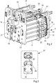
- FIG. 1 shows an ammunition management system 1 according to the invention, disposed in an automatic cannon 2.
- the ammunition management system comprises an ammunition feed mechanism 3, also referred to as an ammunition feed device, and a rotatable ammunition magazine 4 comprising ammunition 5, also referred to as ammunition shot or ammunition unit, wherein the ammunition magazine 4 and ammunition feed mechanism 3 are driven by a common drive device 6.
- the ammunition magazine 4 is rotatably and detachably arranged directly on the breech casing 7 of the automatic cannon 2, below the ammunition feed mechanism 3, via two front rotation shafts 8 and two rear bolts 9.
- ammunition units 5 are fed from the ammunition magazine 4 to the breech casing 7 via the ammunition feed device 3.
- the drive device 6 comprises an electric motor 10 for driving the ammunition magazine 4 and the ammunition feed mechanism 3 via a chain drive mechanism 11 disposed in the front and rear end walls 12, 13 of the ammunition magazine 4, Figure 2 .
- the ammunition management system 1 is arranged such that, when the ammunition magazine 4 rotates anti-clockwise (viewed from the rear from the rear end wall 13), ammunition is fed from the ammunition magazine 4 to the breech casing 7 of the cannon. Clockwise rotation of the ammunition magazine 4 is used for emptying of ammunition 5 and in the sorting of mixed ammunition 5 in the ammunition magazine 4. Adjacent to the chain drive mechanism 11 and the ammunition feed mechanism 3 there is arranged a disengaging device 14, configured as a claw coupling, which makes it possible to rotate the ammunition magazine 4 even when the ammunition feed device 3 is stationary. By alternating between anti-clockwise and clockwise rotation of the ammunition magazine 4, corresponding to feed-in/feed-out of ammunition 5 to/from the ammunition feed device 3, it is possible to sort the ammunition 5 in the ammunition magazine 4 according to a preselected sorting program.
- the ammunition management system 1 comprises, apart from the ammunition magazine 4, the feed mechanism 3, the chain drive mechanism 11 and the disengaging device 14, as well as an angle encoder 15 for registering the relative position of the ammunition 5 in the ammunition magazine 4.
- the ammunition magazine 4 is accessible in a simple and manageable manner, for example in connection with servicing or when the ammunition magazine 4 needs to be emptied quickly, via two rear, releasable bolts 9 and two handles 15, one on either side of the ammunition magazine 4, with which the ammunition magazine 4 can be lowered from a tilted-up position into a tilted-down position.
- a protruding locking shaft coupled to a cardan joint, which has to be released before the ammunition magazine 4 can be lowered.
- the ammunition magazine 4 with ammunition 5, chain drive mechanism 11 and end walls 12, 13 is held together by two beams 17, mounted between the end walls 12, 13, and a centre bracket 27 fitted to the beams 17.
- End walls 12, 13 and the beams 17 are preferably made of aluminium or steel.
- the ammunition magazine 4 is driven by the chain drive mechanism 11 via two separate chains 18 disposed in the front end wall 12 and in the rear end wall 13 respectively.
- the chains 18 are synchronized with one another via a number of drive shafts 19, which distribute the drive force from the electric motor 10 to the chains 18.
- six drive shafts 19 and six chain wheels 20 are used, which ensures that the chains 18 are always synchronized with one another, even if one of the chains 18 is loose.
- the degree of pretension is monitored via graduated scales 24, arranged adjacent to a chain holder 23.
- the ammunition 5 is transported around in the ammunition magazine 4 via/on guide rods 25, which are coupled to the chain drive mechanism 11 via mounting pins 26.
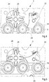
- the star wheels 28, Figure 4 are mechanically synchronized with the chains 18 and will always correspond with the space (distance) between the ammunition 5.
- the primary task of the star wheels 28 is to feed ammunition 5 to and from the ammunition feed device 3 via spring-loaded pawls 29, Figure 4 and Figure 5 respectively.
- the chains 18 rotate clockwise.
- the star wheels 28 press the ammunition 5 against the spring-loaded pawls 29, which guide ammunition 5 out from the ammunition magazine 4 and onwards into the ammunition feed device 3, Fig. 4 .
- a hatch 30 intended for manual loading/unloading of ammunition 5 to/from the ammunition magazine 4.
- ammunition 5 is introduced into the ammunition magazine 4 via the hatch 30 into a position in which the flange 31 of the ammunition casing meets a stop in the end wall 13, whereafter the ammunition unit 5 is pressed down into its intended position with the aid of a spring-loaded hook 32.
- a spring-loaded ejection mechanism 34 is activated, which ejects the ammunition 5, Figure 6a and 6b .
- the ammunition magazine 4 and the ammunition feed device 3 are driven by a drive unit comprising a planetary gear, a servomotor 10 having a built-in absolute angle encoder (internal angle encoder), and a mechanical brake.
- a drive unit comprising a planetary gear, a servomotor 10 having a built-in absolute angle encoder (internal angle encoder), and a mechanical brake.
- the internal encoder in the servomotor 10 is used to monitor the ammunition magazine 4. If a power cut occurs, the mechanical brake will be activated, whereupon the ammunition magazine 4 comes to a halt and is locked. It is nevertheless still possible to release the brake on condition that the power system is engaged, the magazine 4 being manually rotatable with the aid of a hand-operated crankshaft.
- the drive device 6 comprises an electric motor 10 for driving the ammunition magazine 4 and the ammunition feed mechanism 3 via a chain drive mechanism 11 disposed in the front and rear end walls 12, 13 of the ammunition magazine 4.
- the chain mechanism 11 is driven via a front drive shaft 37 on the front end wall 12.
- To the front drive shaft 37 is also fitted a planetary gear 35, to which the drive shaft of the electric motor 10 is connected via a fixed hub 36.
- the hub 36 is mounted with a hexagon socket head screw, which is accessible via the mounting plate.
- the motor 10 has two connections, an X1 connection for mains supply and an X2 connection for signal.
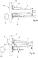
- An external angle encoder 38 is positioned on the front end wall 12 of the ammunition magazine 4, in which it is mounted on one of the drive shafts via a flexible damping device in order to minimize the effect of harmful shocks or vibrations.
- the external encoder 38 is used only to verify that position of the ammunition 5 which is given by the internal encoder in the servomotor 10.
- the movement of the ammunition magazine 4 is synchronized with the star wheel 28 in the chain drive mechanism 11 via three gearwheels in the decoupling device 14.
- the decoupling device 14 is always deactivated.
- the ammunition feed device 3 In order to enable reorganization and shifting of ammunition 5 between different ammunition types 5 in the ammunition magazine 4, the ammunition feed device 3 must be able to be decoupled from the ammunition magazine 4, i.e. the decoupling device 14 must be activated, which is done with the aid of a solenoid, which controls the decoupling device 14.
- the decoupling device 14 comprises a rear movable claw, which is activated once the solenoid has pressed back the claw into its rear position. In the event of a power cut, the decoupling device 14 will remain deactivated due to pre-loaded helical springs which act on the disengaging device 14 such that the movable claw of the decoupling device 14 is kept pressed back in its rear position.
- An inductive sensor 39, Figure 9 directed towards the flange of the movable claw, signals when the claw changes position, i.e. when the decoupling device 14 is activated.
- the ammunition magazine 4 is connected to the ammunition feed device 3 via a coupling shaft 40, Figure 9 , configured with square cross section, which makes it impossible to connect the magazine 4 to the ammunition feed device 3 incorrectly.
- the ammunition magazine 4 In order to remove or lower the ammunition magazine 4, the ammunition magazine 4 must be decoupled from the ammunition feed device 3.
- the decoupling can be realized by connecting an M8-screw to the coupling shaft 40 and subsequently pulling on the coupling shaft 40 such that it comes loose from the cardan joint in the ammunition feed device 3.
Claims (8)
- Système de gestion de munitions (1) destiné à tirer des munitions (5) mixtes dans un canon automatique (2), comprenant un chargeur de munitions (4) rotatif, comprenant des munitions (5), un boîtier de culasse (7) et un dispositif d'alimentation en munitions (3), où
le système de gestion de munitions (1) comprend un dispositif d'entraînement (6) comprenant un moteur électrique (10) pour entraîner le chargeur de munitions (4) et le dispositif d'alimentation en munitions (3) via un mécanisme d'entraînement à chaîne (11) comprenant deux chaînes séparées (18) disposées dans une paroi d'extrémité avant et une paroi d'extrémité arrière (12, 13), respectivement, dans le chargeur de munitions (4), et des roues en étoile (28) synchronisées mécaniquement avec les chaînes (18) pour amener les munitions (5) vers et depuis le dispositif d'alimentation en munitions (3) via des cliquets à ressort (29), lorsque les roues en étoile (28) pressent les munitions (5) vers les cliquets à ressort (29), qui guident les munitions (5) depuis le chargeur de munitions (4) jusqu'au dispositif de munitions (3) ou lorsque les munitions (5) se déplacent dans la direction opposée dans le chargeur de munitions (4), les cliquets à ressort (29) s'ouvrent lorsque les munitions (5) appuient sur les cliquets (29), et le système de gestion de munitions (1) comprend également un dispositif de découplage (14) configuré comme un accouplement à griffes permettant l'enclenchement et la désolidarisation du chargeur de munitions (4) par rapport au dispositif d'alimentation de munitions (3), de sorte que les munitions (5) peuvent être déplacées entre différentes positions dans le chargeur de munitions (4), ladite roue en étoile (28) et le mécanisme d'entraînement à chaîne (11) étant synchronisés lorsque le dispositif de découplage (14) est dans un état désactivé. - Système de gestion de munitions (1) selon la revendication 1,
caractérisé en ce que le chargeur de munitions (4) est disposé de manière rotative sur le côté inférieur du boîtier de culasse (7) dans la direction verticale par l'intermédiaire de deux arbres de rotation avant (8) et de deux boulons arrière (9), et par l'intermédiaire de deux poignées (15), l'une de chaque côté du chargeur de munitions (4), avec lesquelles le chargeur de munitions (4) peut facilement être abaissé d'une position inclinée vers le haut à une position inclinée vers le bas pendant l'entretien ou pendant la vidange du chargeur (4). - Système de gestion de munitions (1) selon la revendication 1,
caractérisé en ce que le chargeur de munitions (4) peut être entraîné par au moins deux chaînes séparées (18), qui sont synchronisées l'une avec l'autre par un système d'arbres d'entraînement (19) et de roues à chaîne (20), lesquels arbres d'entraînement (19) et roues à chaîne (20) répartissent la force d'entraînement entre les chaînes (18) et garantissent que les chaînes (18) sont toujours synchronisées l'une avec l'autre. - Système de gestion de munitions (1) selon la revendication 3,
caractérisé en ce que les chaînes (18) sont réglables manuellement par l'intermédiaire d'un mécanisme de réglage de chaîne (21), comprenant des vis de réglage (22) reliées à des supports de chaîne (23) pouvant être relevés et abaissés sur les parois d'extrémité (12), (13), disposés de telle sorte que, lorsqu'un support de chaîne (23) est réglé vers le haut dans la direction de hauteur, la précontrainte dans la chaîne (18) augmente et, lorsqu'un support de chaîne (23) est réglé vers le bas dans la direction de hauteur, la précontrainte diminue. - Système de gestion de munitions (1) selon la revendication 1,
caractérisé en ce que le chargeur de munitions (4) comprend une trappe (30) pour l'alimentation et l'évacuation manuelles des munitions (5) vers le chargeur de munitions (4). - Système de gestion de munitions (1) selon la revendication 1, caractérisé en ce que le chargeur de munitions (4) comprend un codeur d'angle externe (38), configuré pour vérifier la position des munitions (5) dans le chargeur de munitions (4), dans lequel le codeur d'angle (38) est monté sur l'un des arbres d'entraînement du chargeur de munitions (4) via un dispositif d'amortissement flexible afin de minimiser l'effet de chocs ou de vibrations nuisibles.
- Système de gestion de munitions (1) selon la revendication 1,
caractérisé en ce que le chargeur de munitions (4) est relié au dispositif d'alimentation en munitions (3) par l'intermédiaire d'un arbre d'accouplement (40) configuré avec une section transversale carrée, ce qui rend impossible la connexion du chargeur (4) au dispositif d'alimentation en munitions (3) de manière incorrecte. - Procédé pour trier des munitions mixtes (5) dans un système de gestion de munitions (1) selon l'une quelconque des revendications 1 à 7, comprenant les étapes suivantes :l'alimentation en munitions (5) du chargeur de munitions (4) au dispositif d'alimentation en munitions (3) ;le découplage du chargeur de munitions (4) du dispositif d'alimentation en munitions (3) par l'intermédiaire du dispositif de découplage (14);la rotation du chargeur de munitions (4) dans une nouvelle position;le couplage du chargeur de munitions (4) avec le dispositif d'alimentation en munitions (3); etl'alimentation en munitions (5) à partir du dispositif d'alimentation en munitions (3) dans la nouvelle position dans le chargeur de munitions (4), après que lesdites étapes sont répétées jusqu'à ce que toutes les munitions (5) aient été triées dans leurs positions prédéterminées.
Priority Applications (1)
| Application Number | Priority Date | Filing Date | Title |
|---|---|---|---|
| PL14859916T PL3066408T3 (pl) | 2013-11-07 | 2014-11-03 | System zarządzania amunicją do mieszanych typów amunicji |
Applications Claiming Priority (2)
| Application Number | Priority Date | Filing Date | Title |
|---|---|---|---|
| SE1300692A SE537591C2 (sv) | 2013-11-07 | 2013-11-07 | Ammunitionshanteringssystem och metod för sortering av blandade ammunitionstyper i ett magasin |
| PCT/SE2014/000130 WO2015069167A1 (fr) | 2013-11-07 | 2014-11-03 | Système de gestion et procédé permettant de trier des types de munition mixte |
Publications (3)
| Publication Number | Publication Date |
|---|---|
| EP3066408A1 EP3066408A1 (fr) | 2016-09-14 |
| EP3066408A4 EP3066408A4 (fr) | 2017-03-22 |
| EP3066408B1 true EP3066408B1 (fr) | 2018-09-26 |
Family
ID=53041817
Family Applications (1)
| Application Number | Title | Priority Date | Filing Date |
|---|---|---|---|
| EP14859916.0A Active EP3066408B1 (fr) | 2013-11-07 | 2014-11-03 | Système de gestion et procédé permettant de trier des types mixtes de munition |
Country Status (8)
| Country | Link |
|---|---|
| US (1) | US9841247B2 (fr) |
| EP (1) | EP3066408B1 (fr) |
| KR (1) | KR102193501B1 (fr) |
| CA (1) | CA2931780C (fr) |
| PL (1) | PL3066408T3 (fr) |
| SE (1) | SE537591C2 (fr) |
| SG (1) | SG11201604476QA (fr) |
| WO (1) | WO2015069167A1 (fr) |
Families Citing this family (4)
| Publication number | Priority date | Publication date | Assignee | Title |
|---|---|---|---|---|
| SE541259C2 (sv) | 2016-06-21 | 2019-05-21 | Bae Systems Bofors Ab | System och förfarande för påfyllning av ammunition till ett primärmagasin i en automatkanon |
| CN108016618A (zh) * | 2017-12-28 | 2018-05-11 | 深圳城际快机科技有限公司 | 一种弹药发射装置及系统 |
| CN109029063B (zh) * | 2018-07-16 | 2020-06-09 | 哈尔滨工业大学 | 一种连续发射轻小目标装置 |
| TR2022003390A2 (tr) * | 2022-03-07 | 2022-06-21 | Fnss Savunma Sistemleri Anonim Sirketi | Ayarlanabi̇li̇r di̇key mühi̇mmat yükleme mekani̇zmasi |
Citations (22)
| Publication number | Priority date | Publication date | Assignee | Title |
|---|---|---|---|---|
| US1565836A (en) | 1924-10-01 | 1925-12-15 | Webster Thomas Herbert | Ammunition supply apparatus for gun turrets in which two or more guns are mounted |
| US2642688A (en) | 1950-12-06 | 1953-06-23 | Olin Ind Inc | Magazine-conversion unit for firearms |
| US3153368A (en) | 1957-06-03 | 1964-10-20 | Arthur J Stanton | Ammunition transfer mechanism |
| FR1492352A (fr) | 1965-07-30 | 1967-08-18 | Oerlikon Buehrle Holding Ag | Magasin à munitions |
| FR2404827A1 (fr) | 1977-09-28 | 1979-04-27 | Oerlikon Buehrle Ag | Dispositif d'alimentation en cartouches pour armes a feu automatiques |
| US4318331A (en) | 1979-07-06 | 1982-03-09 | Werkzeugmaschinenfabrik Oerlikon-Buhrle Ag | Automatic ammunition loading apparatus for an armored vehicle |
| FR2524136A1 (fr) | 1982-03-27 | 1983-09-30 | Rheinmetall Gmbh | Mecanisme pour alimenter en munitions une arme a double tube |
| US4450750A (en) | 1981-10-20 | 1984-05-29 | Ares, Inc. | Dual shell feeding apparatus, with shell accumulators, for automatic guns |
| FR2707747A1 (fr) | 1993-07-16 | 1995-01-20 | Ferretti Maurice | Dispositif pour rendre inamovible le chargeur d'une arme. |
| US5440964A (en) | 1994-08-03 | 1995-08-15 | Martin Marietta Corporation | Ammunition magazine drive system |
| EP0694750A1 (fr) | 1994-07-22 | 1996-01-31 | CTA International | Système d'alimentation en munitions pour une arme à feu de petit ou de moyen calibre |
| DE19505349A1 (de) | 1995-02-17 | 1996-08-22 | Kuka Wehrtechnik Gmbh | Verfahren zur Verwaltung von Granaten in einem Munitionsmagazin und Vorrichtung zu dessen Durchführung |
| WO1998025098A1 (fr) | 1996-12-02 | 1998-06-11 | Bofors Ab | Procede de rangement, de transport et de ravitaillement de munitions pour pieces d'artillerie et vehicule de ravitaillement conçu a cet effet |
| US6272967B1 (en) | 1999-06-14 | 2001-08-14 | General Dynamics Armament Systems, Inc. | Modular ammunition storage and retrieval system |
| US20030089583A1 (en) | 2001-11-14 | 2003-05-15 | The Laitram Corporation | Compensation for shaft twist in the drive system of modular conveyor belts |
| WO2004025209A1 (fr) | 2002-09-13 | 2004-03-25 | Denel Ltd | Systeme d'alimentation en munitions |
| WO2009049721A1 (fr) | 2007-10-17 | 2009-04-23 | Rheinmetall Waffe Munition Gmbh | Dispositif de contrôle fonctionnel d'un système d'arme assisté par des détecteurs |
| WO2009049710A1 (fr) | 2007-10-17 | 2009-04-23 | Rheinmetall Waffe Munition Gmbh | Système d'alimentation en munitions |
| FR2925149A1 (fr) | 2007-12-13 | 2009-06-19 | Cta Internat Sa | Magasin d'alimentation semi-automatique en munitions d'une arme |
| WO2012084669A1 (fr) | 2010-12-21 | 2012-06-28 | Robert Bosch Gmbh | Machine-outil à main |
| US20120266748A1 (en) | 2009-10-21 | 2012-10-25 | Bae Systems Bofors Ab | Automatic charge magazine |
| JP2013078818A (ja) | 2011-10-03 | 2013-05-02 | Tohnichi Mfg Co Ltd | 角ドライブとこの角ドライブを備えたトルク機器 |
Family Cites Families (13)
| Publication number | Priority date | Publication date | Assignee | Title |
|---|---|---|---|---|
| US2933981A (en) * | 1953-10-26 | 1960-04-26 | Paul E Anderson | Automatic repeating rocket launcher |
| US3376785A (en) * | 1965-06-30 | 1968-04-09 | Bofors Ab | Installation for loading the launching tubes of a depth-charge launcher |
| US3683743A (en) * | 1969-08-01 | 1972-08-15 | Stoner Eugen Morrison | Linkless cartridge feed system |
| US4434700A (en) * | 1982-01-04 | 1984-03-06 | General Electric Company | Automated ammunition mixer |
| DE3227214A1 (de) * | 1982-07-21 | 1984-01-26 | Rheinmetall GmbH, 4000 Düsseldorf | Trommelmagazin fuer grosskalibrige munition |
| FR2664966A1 (fr) * | 1990-07-20 | 1992-01-24 | Creusot Loire | Dispositif de commande de chargement automatique d'un canon. |
| FR2668253B1 (fr) * | 1990-10-17 | 1994-09-30 | Creusot Loire | Dispositif d'identification et de controle de munition d'une arme a feu a chargement automatique et procede pour sa mise en óoeuvre. |
| DE59200441D1 (de) * | 1991-07-30 | 1994-10-06 | Contraves Ag | Vorrichtung zum Zuführen von Patronen vorwiegend zweier verschiedener Munitionsarten zu einer Gatling-Kanone. |
| DE59202019D1 (de) * | 1991-08-30 | 1995-06-01 | Contraves Ag | Vorrichtung zum Zuführen von Patronen vorwiegend zweier verschiedener Munitionsarten zu einer Gatling-Kanone. |
| NO960164D0 (no) * | 1996-01-15 | 1996-01-15 | Oeyvind Isachsen | System for automatisk bestemmelse av ammunisjonstype |
| IT1399814B1 (it) * | 2010-04-27 | 2013-05-03 | Oto Melara Spa | Metodo e sistema di caricamento e scaricamento di proiettili in un caricatore per armi da fuoco. |
| DE102010016963A1 (de) * | 2010-05-17 | 2011-11-17 | Krauss-Maffei Wegmann Gmbh & Co. Kg | Waffensystem, Verfahren zum Verschießen und Erkennen von Munitionskörpern |
| US20160231074A1 (en) * | 2013-11-22 | 2016-08-11 | Systems And Materials Research Corporation | Selective Ammunition Handling System |
-
2013
- 2013-11-07 SE SE1300692A patent/SE537591C2/sv unknown
-
2014
- 2014-11-03 CA CA2931780A patent/CA2931780C/fr active Active
- 2014-11-03 SG SG11201604476QA patent/SG11201604476QA/en unknown
- 2014-11-03 US US15/101,180 patent/US9841247B2/en active Active
- 2014-11-03 PL PL14859916T patent/PL3066408T3/pl unknown
- 2014-11-03 WO PCT/SE2014/000130 patent/WO2015069167A1/fr active Application Filing
- 2014-11-03 KR KR1020167015037A patent/KR102193501B1/ko active IP Right Grant
- 2014-11-03 EP EP14859916.0A patent/EP3066408B1/fr active Active
Patent Citations (22)
| Publication number | Priority date | Publication date | Assignee | Title |
|---|---|---|---|---|
| US1565836A (en) | 1924-10-01 | 1925-12-15 | Webster Thomas Herbert | Ammunition supply apparatus for gun turrets in which two or more guns are mounted |
| US2642688A (en) | 1950-12-06 | 1953-06-23 | Olin Ind Inc | Magazine-conversion unit for firearms |
| US3153368A (en) | 1957-06-03 | 1964-10-20 | Arthur J Stanton | Ammunition transfer mechanism |
| FR1492352A (fr) | 1965-07-30 | 1967-08-18 | Oerlikon Buehrle Holding Ag | Magasin à munitions |
| FR2404827A1 (fr) | 1977-09-28 | 1979-04-27 | Oerlikon Buehrle Ag | Dispositif d'alimentation en cartouches pour armes a feu automatiques |
| US4318331A (en) | 1979-07-06 | 1982-03-09 | Werkzeugmaschinenfabrik Oerlikon-Buhrle Ag | Automatic ammunition loading apparatus for an armored vehicle |
| US4450750A (en) | 1981-10-20 | 1984-05-29 | Ares, Inc. | Dual shell feeding apparatus, with shell accumulators, for automatic guns |
| FR2524136A1 (fr) | 1982-03-27 | 1983-09-30 | Rheinmetall Gmbh | Mecanisme pour alimenter en munitions une arme a double tube |
| FR2707747A1 (fr) | 1993-07-16 | 1995-01-20 | Ferretti Maurice | Dispositif pour rendre inamovible le chargeur d'une arme. |
| EP0694750A1 (fr) | 1994-07-22 | 1996-01-31 | CTA International | Système d'alimentation en munitions pour une arme à feu de petit ou de moyen calibre |
| US5440964A (en) | 1994-08-03 | 1995-08-15 | Martin Marietta Corporation | Ammunition magazine drive system |
| DE19505349A1 (de) | 1995-02-17 | 1996-08-22 | Kuka Wehrtechnik Gmbh | Verfahren zur Verwaltung von Granaten in einem Munitionsmagazin und Vorrichtung zu dessen Durchführung |
| WO1998025098A1 (fr) | 1996-12-02 | 1998-06-11 | Bofors Ab | Procede de rangement, de transport et de ravitaillement de munitions pour pieces d'artillerie et vehicule de ravitaillement conçu a cet effet |
| US6272967B1 (en) | 1999-06-14 | 2001-08-14 | General Dynamics Armament Systems, Inc. | Modular ammunition storage and retrieval system |
| US20030089583A1 (en) | 2001-11-14 | 2003-05-15 | The Laitram Corporation | Compensation for shaft twist in the drive system of modular conveyor belts |
| WO2004025209A1 (fr) | 2002-09-13 | 2004-03-25 | Denel Ltd | Systeme d'alimentation en munitions |
| WO2009049721A1 (fr) | 2007-10-17 | 2009-04-23 | Rheinmetall Waffe Munition Gmbh | Dispositif de contrôle fonctionnel d'un système d'arme assisté par des détecteurs |
| WO2009049710A1 (fr) | 2007-10-17 | 2009-04-23 | Rheinmetall Waffe Munition Gmbh | Système d'alimentation en munitions |
| FR2925149A1 (fr) | 2007-12-13 | 2009-06-19 | Cta Internat Sa | Magasin d'alimentation semi-automatique en munitions d'une arme |
| US20120266748A1 (en) | 2009-10-21 | 2012-10-25 | Bae Systems Bofors Ab | Automatic charge magazine |
| WO2012084669A1 (fr) | 2010-12-21 | 2012-06-28 | Robert Bosch Gmbh | Machine-outil à main |
| JP2013078818A (ja) | 2011-10-03 | 2013-05-02 | Tohnichi Mfg Co Ltd | 角ドライブとこの角ドライブを備えたトルク機器 |
Non-Patent Citations (1)
| Title |
|---|
| CTA INTERNATIONAL: "40mm CTWS Supporting UK France", 40TH ANNUAL ARMAMENT SYSTEMS GUNS-AMMUNITION-ROCKETS-MISSILES CONFERENCE AND EXHIBITION, 25 April 2005 (2005-04-25) - 28 April 2005 (2005-04-28), pages 59pp, XP055618068 |
Also Published As
| Publication number | Publication date |
|---|---|
| CA2931780C (fr) | 2017-12-19 |
| KR20160090307A (ko) | 2016-07-29 |
| EP3066408A4 (fr) | 2017-03-22 |
| EP3066408A1 (fr) | 2016-09-14 |
| US9841247B2 (en) | 2017-12-12 |
| US20160370136A1 (en) | 2016-12-22 |
| CA2931780A1 (fr) | 2015-05-14 |
| PL3066408T3 (pl) | 2019-02-28 |
| WO2015069167A1 (fr) | 2015-05-14 |
| SG11201604476QA (en) | 2016-07-28 |
| KR102193501B1 (ko) | 2020-12-21 |
| SE537591C2 (sv) | 2015-07-07 |
| SE1300692A1 (sv) | 2015-05-08 |
Similar Documents
| Publication | Publication Date | Title |
|---|---|---|
| EP3066408B1 (fr) | Système de gestion et procédé permettant de trier des types mixtes de munition | |
| US7669512B2 (en) | Ammunition feed system with an automatic clutch | |
| US10066892B1 (en) | Modular automated mortar weapon for mobile applications | |
| EP2491330B1 (fr) | Chargeur à charge automatique | |
| EP3472550B1 (fr) | Système et procédé permettant un transfert réversible d'une munition entre un magasin primaire et un magasin secondaire dans un canon automatique | |
| KR101695173B1 (ko) | 완구용 총기의 탄창용 탄알 자동 공급 장치 | |
| KR102630302B1 (ko) | 회전 플레이트를 구비한 중형 구경 탄약을 공급하기 위한 디바이스 | |
| DE3050016C2 (de) | Zweistufen-Granatenzufuhrgerät mit Granatenzufuhrpfadsteuerung | |
| EP2282157B1 (fr) | Dispositif d'armement télécommandable pour des mitrailleuses dotées d'un élément coulissant d'armement | |
| JPH09323833A (ja) | テーパ状物品の供給装着装置 | |
| EP3607261B1 (fr) | Dispositif pour charger une arme à canon avec des corps de munition | |
| KR20170014529A (ko) | 탄 공급장치를 구비한 사격장 통제시스템 | |
| JPS61143700A (ja) | 外力駆動火砲のための遅延点火の監視装置 | |
| US20220299301A1 (en) | Progressive ammunition press system | |
| RU2498195C1 (ru) | Транспортно-заряжающая машина для самоходного артиллерийского орудия | |
| US548096A (en) | Machine-gun | |
| CN217877322U (zh) | 一种筛选排列供弹装置及玩具枪 | |
| EP1216392B1 (fr) | Systeme de manipulation des munitions | |
| RU2243473C9 (ru) | Салютная пушка | |
| US7581484B1 (en) | Weapon system retention device | |
| PL222386B1 (pl) | Automat ładowania pocisków czołgowych |
Legal Events
| Date | Code | Title | Description |
|---|---|---|---|
| PUAI | Public reference made under article 153(3) epc to a published international application that has entered the european phase |
Free format text: ORIGINAL CODE: 0009012 |
|
| 17P | Request for examination filed |
Effective date: 20160607 |
|
| AK | Designated contracting states |
Kind code of ref document: A1 Designated state(s): AL AT BE BG CH CY CZ DE DK EE ES FI FR GB GR HR HU IE IS IT LI LT LU LV MC MK MT NL NO PL PT RO RS SE SI SK SM TR |
|
| AX | Request for extension of the european patent |
Extension state: BA ME |
|
| DAX | Request for extension of the european patent (deleted) | ||
| A4 | Supplementary search report drawn up and despatched |
Effective date: 20170221 |
|
| RIC1 | Information provided on ipc code assigned before grant |
Ipc: F41A 9/37 20060101ALI20170215BHEP Ipc: F41A 9/76 20060101AFI20170215BHEP Ipc: F41A 9/04 20060101ALI20170215BHEP |
|
| GRAP | Despatch of communication of intention to grant a patent |
Free format text: ORIGINAL CODE: EPIDOSNIGR1 |
|
| STAA | Information on the status of an ep patent application or granted ep patent |
Free format text: STATUS: GRANT OF PATENT IS INTENDED |
|
| INTG | Intention to grant announced |
Effective date: 20180504 |
|
| GRAS | Grant fee paid |
Free format text: ORIGINAL CODE: EPIDOSNIGR3 |
|
| GRAA | (expected) grant |
Free format text: ORIGINAL CODE: 0009210 |
|
| STAA | Information on the status of an ep patent application or granted ep patent |
Free format text: STATUS: THE PATENT HAS BEEN GRANTED |
|
| AK | Designated contracting states |
Kind code of ref document: B1 Designated state(s): AL AT BE BG CH CY CZ DE DK EE ES FI FR GB GR HR HU IE IS IT LI LT LU LV MC MK MT NL NO PL PT RO RS SE SI SK SM TR |
|
| REG | Reference to a national code |
Ref country code: GB Ref legal event code: FG4D |
|
| RIN1 | Information on inventor provided before grant (corrected) |
Inventor name: PALMLOEV, ULF Inventor name: TRULSSON, PER Inventor name: NILSSON, ANDREAS |
|
| REG | Reference to a national code |
Ref country code: CH Ref legal event code: EP |
|
| REG | Reference to a national code |
Ref country code: AT Ref legal event code: REF Ref document number: 1046516 Country of ref document: AT Kind code of ref document: T Effective date: 20181015 |
|
| REG | Reference to a national code |
Ref country code: IE Ref legal event code: FG4D |
|
| REG | Reference to a national code |
Ref country code: DE Ref legal event code: R096 Ref document number: 602014033164 Country of ref document: DE |
|
| REG | Reference to a national code |
Ref country code: NL Ref legal event code: MP Effective date: 20180926 |
|
| PG25 | Lapsed in a contracting state [announced via postgrant information from national office to epo] |
Ref country code: SE Free format text: LAPSE BECAUSE OF FAILURE TO SUBMIT A TRANSLATION OF THE DESCRIPTION OR TO PAY THE FEE WITHIN THE PRESCRIBED TIME-LIMIT Effective date: 20180926 Ref country code: BG Free format text: LAPSE BECAUSE OF FAILURE TO SUBMIT A TRANSLATION OF THE DESCRIPTION OR TO PAY THE FEE WITHIN THE PRESCRIBED TIME-LIMIT Effective date: 20181226 Ref country code: RS Free format text: LAPSE BECAUSE OF FAILURE TO SUBMIT A TRANSLATION OF THE DESCRIPTION OR TO PAY THE FEE WITHIN THE PRESCRIBED TIME-LIMIT Effective date: 20180926 Ref country code: GR Free format text: LAPSE BECAUSE OF FAILURE TO SUBMIT A TRANSLATION OF THE DESCRIPTION OR TO PAY THE FEE WITHIN THE PRESCRIBED TIME-LIMIT Effective date: 20181227 Ref country code: LT Free format text: LAPSE BECAUSE OF FAILURE TO SUBMIT A TRANSLATION OF THE DESCRIPTION OR TO PAY THE FEE WITHIN THE PRESCRIBED TIME-LIMIT Effective date: 20180926 Ref country code: FI Free format text: LAPSE BECAUSE OF FAILURE TO SUBMIT A TRANSLATION OF THE DESCRIPTION OR TO PAY THE FEE WITHIN THE PRESCRIBED TIME-LIMIT Effective date: 20180926 |
|
| REG | Reference to a national code |
Ref country code: LT Ref legal event code: MG4D Ref country code: NO Ref legal event code: T2 Effective date: 20180926 |
|
| PG25 | Lapsed in a contracting state [announced via postgrant information from national office to epo] |
Ref country code: LV Free format text: LAPSE BECAUSE OF FAILURE TO SUBMIT A TRANSLATION OF THE DESCRIPTION OR TO PAY THE FEE WITHIN THE PRESCRIBED TIME-LIMIT Effective date: 20180926 Ref country code: HR Free format text: LAPSE BECAUSE OF FAILURE TO SUBMIT A TRANSLATION OF THE DESCRIPTION OR TO PAY THE FEE WITHIN THE PRESCRIBED TIME-LIMIT Effective date: 20180926 Ref country code: AL Free format text: LAPSE BECAUSE OF FAILURE TO SUBMIT A TRANSLATION OF THE DESCRIPTION OR TO PAY THE FEE WITHIN THE PRESCRIBED TIME-LIMIT Effective date: 20180926 |
|
| PG25 | Lapsed in a contracting state [announced via postgrant information from national office to epo] |
Ref country code: CZ Free format text: LAPSE BECAUSE OF FAILURE TO SUBMIT A TRANSLATION OF THE DESCRIPTION OR TO PAY THE FEE WITHIN THE PRESCRIBED TIME-LIMIT Effective date: 20180926 Ref country code: EE Free format text: LAPSE BECAUSE OF FAILURE TO SUBMIT A TRANSLATION OF THE DESCRIPTION OR TO PAY THE FEE WITHIN THE PRESCRIBED TIME-LIMIT Effective date: 20180926 Ref country code: NL Free format text: LAPSE BECAUSE OF FAILURE TO SUBMIT A TRANSLATION OF THE DESCRIPTION OR TO PAY THE FEE WITHIN THE PRESCRIBED TIME-LIMIT Effective date: 20180926 Ref country code: RO Free format text: LAPSE BECAUSE OF FAILURE TO SUBMIT A TRANSLATION OF THE DESCRIPTION OR TO PAY THE FEE WITHIN THE PRESCRIBED TIME-LIMIT Effective date: 20180926 Ref country code: ES Free format text: LAPSE BECAUSE OF FAILURE TO SUBMIT A TRANSLATION OF THE DESCRIPTION OR TO PAY THE FEE WITHIN THE PRESCRIBED TIME-LIMIT Effective date: 20180926 Ref country code: IS Free format text: LAPSE BECAUSE OF FAILURE TO SUBMIT A TRANSLATION OF THE DESCRIPTION OR TO PAY THE FEE WITHIN THE PRESCRIBED TIME-LIMIT Effective date: 20190126 |
|
| PG25 | Lapsed in a contracting state [announced via postgrant information from national office to epo] |
Ref country code: SK Free format text: LAPSE BECAUSE OF FAILURE TO SUBMIT A TRANSLATION OF THE DESCRIPTION OR TO PAY THE FEE WITHIN THE PRESCRIBED TIME-LIMIT Effective date: 20180926 Ref country code: PT Free format text: LAPSE BECAUSE OF FAILURE TO SUBMIT A TRANSLATION OF THE DESCRIPTION OR TO PAY THE FEE WITHIN THE PRESCRIBED TIME-LIMIT Effective date: 20190126 Ref country code: SM Free format text: LAPSE BECAUSE OF FAILURE TO SUBMIT A TRANSLATION OF THE DESCRIPTION OR TO PAY THE FEE WITHIN THE PRESCRIBED TIME-LIMIT Effective date: 20180926 |
|
| REG | Reference to a national code |
Ref country code: DE Ref legal event code: R026 Ref document number: 602014033164 Country of ref document: DE |
|
| PLBI | Opposition filed |
Free format text: ORIGINAL CODE: 0009260 |
|
| 26 | Opposition filed |
Opponent name: CTA INTERNATIONAL Effective date: 20190620 |
|
| PG25 | Lapsed in a contracting state [announced via postgrant information from national office to epo] |
Ref country code: LU Free format text: LAPSE BECAUSE OF NON-PAYMENT OF DUE FEES Effective date: 20181103 Ref country code: MC Free format text: LAPSE BECAUSE OF FAILURE TO SUBMIT A TRANSLATION OF THE DESCRIPTION OR TO PAY THE FEE WITHIN THE PRESCRIBED TIME-LIMIT Effective date: 20180926 Ref country code: DK Free format text: LAPSE BECAUSE OF FAILURE TO SUBMIT A TRANSLATION OF THE DESCRIPTION OR TO PAY THE FEE WITHIN THE PRESCRIBED TIME-LIMIT Effective date: 20180926 |
|
| PLAX | Notice of opposition and request to file observation + time limit sent |
Free format text: ORIGINAL CODE: EPIDOSNOBS2 |
|
| REG | Reference to a national code |
Ref country code: IE Ref legal event code: MM4A |
|
| PG25 | Lapsed in a contracting state [announced via postgrant information from national office to epo] |
Ref country code: SI Free format text: LAPSE BECAUSE OF FAILURE TO SUBMIT A TRANSLATION OF THE DESCRIPTION OR TO PAY THE FEE WITHIN THE PRESCRIBED TIME-LIMIT Effective date: 20180926 Ref country code: IE Free format text: LAPSE BECAUSE OF NON-PAYMENT OF DUE FEES Effective date: 20181103 |
|
| PLBB | Reply of patent proprietor to notice(s) of opposition received |
Free format text: ORIGINAL CODE: EPIDOSNOBS3 |
|
| PG25 | Lapsed in a contracting state [announced via postgrant information from national office to epo] |
Ref country code: MT Free format text: LAPSE BECAUSE OF NON-PAYMENT OF DUE FEES Effective date: 20181103 |
|
| PG25 | Lapsed in a contracting state [announced via postgrant information from national office to epo] |
Ref country code: MK Free format text: LAPSE BECAUSE OF NON-PAYMENT OF DUE FEES Effective date: 20180926 Ref country code: HU Free format text: LAPSE BECAUSE OF FAILURE TO SUBMIT A TRANSLATION OF THE DESCRIPTION OR TO PAY THE FEE WITHIN THE PRESCRIBED TIME-LIMIT; INVALID AB INITIO Effective date: 20141103 Ref country code: CY Free format text: LAPSE BECAUSE OF FAILURE TO SUBMIT A TRANSLATION OF THE DESCRIPTION OR TO PAY THE FEE WITHIN THE PRESCRIBED TIME-LIMIT Effective date: 20180926 |
|
| REG | Reference to a national code |
Ref country code: DE Ref legal event code: R100 Ref document number: 602014033164 Country of ref document: DE |
|
| PLCK | Communication despatched that opposition was rejected |
Free format text: ORIGINAL CODE: EPIDOSNREJ1 |
|
| PLBN | Opposition rejected |
Free format text: ORIGINAL CODE: 0009273 |
|
| STAA | Information on the status of an ep patent application or granted ep patent |
Free format text: STATUS: OPPOSITION REJECTED |
|
| 27O | Opposition rejected |
Effective date: 20210112 |
|
| REG | Reference to a national code |
Ref country code: AT Ref legal event code: UEP Ref document number: 1046516 Country of ref document: AT Kind code of ref document: T Effective date: 20180926 |
|
| PGFP | Annual fee paid to national office [announced via postgrant information from national office to epo] |
Ref country code: PL Payment date: 20221018 Year of fee payment: 9 Ref country code: BE Payment date: 20221128 Year of fee payment: 9 |
|
| P01 | Opt-out of the competence of the unified patent court (upc) registered |
Effective date: 20230526 |
|
| PGFP | Annual fee paid to national office [announced via postgrant information from national office to epo] |
Ref country code: GB Payment date: 20231127 Year of fee payment: 10 |
|
| PGFP | Annual fee paid to national office [announced via postgrant information from national office to epo] |
Ref country code: TR Payment date: 20231024 Year of fee payment: 10 Ref country code: NO Payment date: 20231129 Year of fee payment: 10 Ref country code: IT Payment date: 20231122 Year of fee payment: 10 Ref country code: FR Payment date: 20231127 Year of fee payment: 10 Ref country code: DE Payment date: 20231129 Year of fee payment: 10 Ref country code: CH Payment date: 20231202 Year of fee payment: 10 Ref country code: AT Payment date: 20231019 Year of fee payment: 10 |
|
| PGFP | Annual fee paid to national office [announced via postgrant information from national office to epo] |
Ref country code: PL Payment date: 20231018 Year of fee payment: 10 Ref country code: BE Payment date: 20231127 Year of fee payment: 10 |