EP3066408B1 - Management system and method for sorting mixed ammunition types - Google Patents
Management system and method for sorting mixed ammunition types Download PDFInfo
- Publication number
- EP3066408B1 EP3066408B1 EP14859916.0A EP14859916A EP3066408B1 EP 3066408 B1 EP3066408 B1 EP 3066408B1 EP 14859916 A EP14859916 A EP 14859916A EP 3066408 B1 EP3066408 B1 EP 3066408B1
- Authority
- EP
- European Patent Office
- Prior art keywords
- ammunition
- magazine
- management system
- chain
- feed device
- Prior art date
- Legal status (The legal status is an assumption and is not a legal conclusion. Google has not performed a legal analysis and makes no representation as to the accuracy of the status listed.)
- Active
Links
- 238000000034 method Methods 0.000 title claims description 5
- 230000007246 mechanism Effects 0.000 claims description 29
- 230000001360 synchronised effect Effects 0.000 claims description 10
- 230000008878 coupling Effects 0.000 claims description 8
- 238000010168 coupling process Methods 0.000 claims description 8
- 238000005859 coupling reaction Methods 0.000 claims description 8
- 210000000078 claw Anatomy 0.000 claims description 7
- 238000010304 firing Methods 0.000 claims description 7
- 230000000694 effects Effects 0.000 claims description 4
- 238000013016 damping Methods 0.000 claims description 3
- 230000007423 decrease Effects 0.000 claims description 3
- 230000035939 shock Effects 0.000 claims description 3
- 229910000831 Steel Inorganic materials 0.000 description 1
- XAGFODPZIPBFFR-UHFFFAOYSA-N aluminium Chemical compound [Al] XAGFODPZIPBFFR-UHFFFAOYSA-N 0.000 description 1
- 229910052782 aluminium Inorganic materials 0.000 description 1
- 239000004411 aluminium Substances 0.000 description 1
- 230000001419 dependent effect Effects 0.000 description 1
- 230000001939 inductive effect Effects 0.000 description 1
- 230000007257 malfunction Effects 0.000 description 1
- 238000012544 monitoring process Methods 0.000 description 1
- 230000008521 reorganization Effects 0.000 description 1
- 239000010959 steel Substances 0.000 description 1
Images


Classifications
-
- F—MECHANICAL ENGINEERING; LIGHTING; HEATING; WEAPONS; BLASTING
- F41—WEAPONS
- F41A—FUNCTIONAL FEATURES OR DETAILS COMMON TO BOTH SMALLARMS AND ORDNANCE, e.g. CANNONS; MOUNTINGS FOR SMALLARMS OR ORDNANCE
- F41A9/00—Feeding or loading of ammunition; Magazines; Guiding means for the extracting of cartridges
- F41A9/61—Magazines
- F41A9/64—Magazines for unbelted ammunition
- F41A9/76—Magazines having an endless-chain conveyor
-
- F—MECHANICAL ENGINEERING; LIGHTING; HEATING; WEAPONS; BLASTING
- F41—WEAPONS
- F41A—FUNCTIONAL FEATURES OR DETAILS COMMON TO BOTH SMALLARMS AND ORDNANCE, e.g. CANNONS; MOUNTINGS FOR SMALLARMS OR ORDNANCE
- F41A9/00—Feeding or loading of ammunition; Magazines; Guiding means for the extracting of cartridges
- F41A9/01—Feeding of unbelted ammunition
- F41A9/04—Feeding of unbelted ammunition using endless-chain belts carrying a plurality of ammunition
-
- F—MECHANICAL ENGINEERING; LIGHTING; HEATING; WEAPONS; BLASTING
- F41—WEAPONS
- F41A—FUNCTIONAL FEATURES OR DETAILS COMMON TO BOTH SMALLARMS AND ORDNANCE, e.g. CANNONS; MOUNTINGS FOR SMALLARMS OR ORDNANCE
- F41A9/00—Feeding or loading of ammunition; Magazines; Guiding means for the extracting of cartridges
- F41A9/37—Feeding two or more kinds of ammunition to the same gun; Feeding from two sides
-
- F—MECHANICAL ENGINEERING; LIGHTING; HEATING; WEAPONS; BLASTING
- F41—WEAPONS
- F41A—FUNCTIONAL FEATURES OR DETAILS COMMON TO BOTH SMALLARMS AND ORDNANCE, e.g. CANNONS; MOUNTINGS FOR SMALLARMS OR ORDNANCE
- F41A9/00—Feeding or loading of ammunition; Magazines; Guiding means for the extracting of cartridges
- F41A9/61—Magazines
Definitions
- the present invention relates to an ammunition management system and to a method for sorting and firing mixed ammunition types in an automatic cannon. Included ammunition types can differ in number and type.
- a problem with the said ammunition management systems is the use of a plurality of ammunition magazines and a plurality of feed chains, which makes the systems complex and increases the risk of malfunction, thereby resulting in fire stoppages.
- the object of the present is to solve, inter alia, these problems.
- a principal object of the present invention has been to provide a simple and safe ammunition management system for firing mixed ammunition types in an automatic cannon, having few moving parts, high ammunition transfer speed and high reliability, in which the risk of fire stoppages is low.
- the invention is an ammunition management system according to claim 1. Further embodiments are disclosed in dependent claims 2-7.
- the present invention also comprises a method for sorting mixed ammunition types according to claim 8.
- the invention means that the ammunition management system can choose between several different sorting programs.
- the software of the gun keeps track of different ammunition types and their placement in the ammunition magazine. No manual sorting is required.
- the invention solves the drawbacks which arise where a plurality of ammunition magazines are used in the sorting of different ammunition types.
- the use of just one ammunition magazine offers the advantages, above all, of a more lightweight product which is simpler, faster and has greater reliability.
- FIG. 1 shows an ammunition management system 1 according to the invention, disposed in an automatic cannon 2.
- the ammunition management system comprises an ammunition feed mechanism 3, also referred to as an ammunition feed device, and a rotatable ammunition magazine 4 comprising ammunition 5, also referred to as ammunition shot or ammunition unit, wherein the ammunition magazine 4 and ammunition feed mechanism 3 are driven by a common drive device 6.
- the ammunition magazine 4 is rotatably and detachably arranged directly on the breech casing 7 of the automatic cannon 2, below the ammunition feed mechanism 3, via two front rotation shafts 8 and two rear bolts 9.
- ammunition units 5 are fed from the ammunition magazine 4 to the breech casing 7 via the ammunition feed device 3.
- the drive device 6 comprises an electric motor 10 for driving the ammunition magazine 4 and the ammunition feed mechanism 3 via a chain drive mechanism 11 disposed in the front and rear end walls 12, 13 of the ammunition magazine 4, Figure 2 .
- the ammunition management system 1 is arranged such that, when the ammunition magazine 4 rotates anti-clockwise (viewed from the rear from the rear end wall 13), ammunition is fed from the ammunition magazine 4 to the breech casing 7 of the cannon. Clockwise rotation of the ammunition magazine 4 is used for emptying of ammunition 5 and in the sorting of mixed ammunition 5 in the ammunition magazine 4. Adjacent to the chain drive mechanism 11 and the ammunition feed mechanism 3 there is arranged a disengaging device 14, configured as a claw coupling, which makes it possible to rotate the ammunition magazine 4 even when the ammunition feed device 3 is stationary. By alternating between anti-clockwise and clockwise rotation of the ammunition magazine 4, corresponding to feed-in/feed-out of ammunition 5 to/from the ammunition feed device 3, it is possible to sort the ammunition 5 in the ammunition magazine 4 according to a preselected sorting program.
- the ammunition management system 1 comprises, apart from the ammunition magazine 4, the feed mechanism 3, the chain drive mechanism 11 and the disengaging device 14, as well as an angle encoder 15 for registering the relative position of the ammunition 5 in the ammunition magazine 4.
- the ammunition magazine 4 is accessible in a simple and manageable manner, for example in connection with servicing or when the ammunition magazine 4 needs to be emptied quickly, via two rear, releasable bolts 9 and two handles 15, one on either side of the ammunition magazine 4, with which the ammunition magazine 4 can be lowered from a tilted-up position into a tilted-down position.
- a protruding locking shaft coupled to a cardan joint, which has to be released before the ammunition magazine 4 can be lowered.
- the ammunition magazine 4 with ammunition 5, chain drive mechanism 11 and end walls 12, 13 is held together by two beams 17, mounted between the end walls 12, 13, and a centre bracket 27 fitted to the beams 17.
- End walls 12, 13 and the beams 17 are preferably made of aluminium or steel.
- the ammunition magazine 4 is driven by the chain drive mechanism 11 via two separate chains 18 disposed in the front end wall 12 and in the rear end wall 13 respectively.
- the chains 18 are synchronized with one another via a number of drive shafts 19, which distribute the drive force from the electric motor 10 to the chains 18.
- six drive shafts 19 and six chain wheels 20 are used, which ensures that the chains 18 are always synchronized with one another, even if one of the chains 18 is loose.
- the degree of pretension is monitored via graduated scales 24, arranged adjacent to a chain holder 23.
- the ammunition 5 is transported around in the ammunition magazine 4 via/on guide rods 25, which are coupled to the chain drive mechanism 11 via mounting pins 26.
- the star wheels 28, Figure 4 are mechanically synchronized with the chains 18 and will always correspond with the space (distance) between the ammunition 5.
- the primary task of the star wheels 28 is to feed ammunition 5 to and from the ammunition feed device 3 via spring-loaded pawls 29, Figure 4 and Figure 5 respectively.
- the chains 18 rotate clockwise.
- the star wheels 28 press the ammunition 5 against the spring-loaded pawls 29, which guide ammunition 5 out from the ammunition magazine 4 and onwards into the ammunition feed device 3, Fig. 4 .
- a hatch 30 intended for manual loading/unloading of ammunition 5 to/from the ammunition magazine 4.
- ammunition 5 is introduced into the ammunition magazine 4 via the hatch 30 into a position in which the flange 31 of the ammunition casing meets a stop in the end wall 13, whereafter the ammunition unit 5 is pressed down into its intended position with the aid of a spring-loaded hook 32.
- a spring-loaded ejection mechanism 34 is activated, which ejects the ammunition 5, Figure 6a and 6b .
- the ammunition magazine 4 and the ammunition feed device 3 are driven by a drive unit comprising a planetary gear, a servomotor 10 having a built-in absolute angle encoder (internal angle encoder), and a mechanical brake.
- a drive unit comprising a planetary gear, a servomotor 10 having a built-in absolute angle encoder (internal angle encoder), and a mechanical brake.
- the internal encoder in the servomotor 10 is used to monitor the ammunition magazine 4. If a power cut occurs, the mechanical brake will be activated, whereupon the ammunition magazine 4 comes to a halt and is locked. It is nevertheless still possible to release the brake on condition that the power system is engaged, the magazine 4 being manually rotatable with the aid of a hand-operated crankshaft.
- the drive device 6 comprises an electric motor 10 for driving the ammunition magazine 4 and the ammunition feed mechanism 3 via a chain drive mechanism 11 disposed in the front and rear end walls 12, 13 of the ammunition magazine 4.
- the chain mechanism 11 is driven via a front drive shaft 37 on the front end wall 12.
- To the front drive shaft 37 is also fitted a planetary gear 35, to which the drive shaft of the electric motor 10 is connected via a fixed hub 36.
- the hub 36 is mounted with a hexagon socket head screw, which is accessible via the mounting plate.
- the motor 10 has two connections, an X1 connection for mains supply and an X2 connection for signal.
- An external angle encoder 38 is positioned on the front end wall 12 of the ammunition magazine 4, in which it is mounted on one of the drive shafts via a flexible damping device in order to minimize the effect of harmful shocks or vibrations.
- the external encoder 38 is used only to verify that position of the ammunition 5 which is given by the internal encoder in the servomotor 10.
- the movement of the ammunition magazine 4 is synchronized with the star wheel 28 in the chain drive mechanism 11 via three gearwheels in the decoupling device 14.
- the decoupling device 14 is always deactivated.
- the ammunition feed device 3 In order to enable reorganization and shifting of ammunition 5 between different ammunition types 5 in the ammunition magazine 4, the ammunition feed device 3 must be able to be decoupled from the ammunition magazine 4, i.e. the decoupling device 14 must be activated, which is done with the aid of a solenoid, which controls the decoupling device 14.
- the decoupling device 14 comprises a rear movable claw, which is activated once the solenoid has pressed back the claw into its rear position. In the event of a power cut, the decoupling device 14 will remain deactivated due to pre-loaded helical springs which act on the disengaging device 14 such that the movable claw of the decoupling device 14 is kept pressed back in its rear position.
- An inductive sensor 39, Figure 9 directed towards the flange of the movable claw, signals when the claw changes position, i.e. when the decoupling device 14 is activated.
- the ammunition magazine 4 is connected to the ammunition feed device 3 via a coupling shaft 40, Figure 9 , configured with square cross section, which makes it impossible to connect the magazine 4 to the ammunition feed device 3 incorrectly.
- the ammunition magazine 4 In order to remove or lower the ammunition magazine 4, the ammunition magazine 4 must be decoupled from the ammunition feed device 3.
- the decoupling can be realized by connecting an M8-screw to the coupling shaft 40 and subsequently pulling on the coupling shaft 40 such that it comes loose from the cardan joint in the ammunition feed device 3.
Description
- The present invention relates to an ammunition management system and to a method for sorting and firing mixed ammunition types in an automatic cannon. Included ammunition types can differ in number and type.
- For present-day ammunition management systems there is a requirement for sorting and firing of mixed ammunition types to proceed quickly, especially in the firing of shots in which shots which are fired in periods following preceding shots are expected to hit the target substantially simultaneously with the previously fired shot or shots.
- Ammunition management systems of the kind stated in the introduction, for firing mixed ammunition types in an automatic cannon, are previously commonly known. Examples of such ammunition management systems are described in documents:
WO 2009/049710 A1 ,WO 2009/049721 A1 andWO 2004025209 A1 . In the stated documents, devices and methods based on sensor-based functions for feeding different types of ammunition shot (M1, M2, M3) from a plurality of different magazines via a plurality of different chains (Z1 - Z3) to an automatic cannon via acommon rotor 2 are described, see, for exampleWO 2009/049721 A1 ,Figure 2 , abstract and description onpage 4.US 6,272,967 provides an ammunition storage and retrieval system for a weapon including a main magazine having a main carrier belt configured to store a plurality of munitions. - A problem with the said ammunition management systems is the use of a plurality of ammunition magazines and a plurality of feed chains, which makes the systems complex and increases the risk of malfunction, thereby resulting in fire stoppages.
- The object of the present is to solve, inter alia, these problems.
- A principal object of the present invention has been to provide a simple and safe ammunition management system for firing mixed ammunition types in an automatic cannon, having few moving parts, high ammunition transfer speed and high reliability, in which the risk of fire stoppages is low.
- This object, as well as other objectives not enumerated here, is satisfactorily met within the scope of that which is stated in the present independent patent claims.
- Thus, according to the present invention, a simple and safe ammunition management system for firing mixed ammunition types in an automatic cannon, having few moving parts and comprising a rotatable ammunition magazine and an ammunition feed device, has been provided.
- The invention is an ammunition management system according to
claim 1. Further embodiments are disclosed in dependent claims 2-7. - According to further aspects of the automatic ammunition management system according to the invention:
- the ammunition magazine is rotatably disposed on the bottom side of the breech casing in the vertical direction via two front rotation shafts and two rear bolts, and via two handles, one on either side of the ammunition magazine, with which the ammunition magazine can easily be lowered from a tilted-up position into a tilted-down position during servicing or during emptying of the magazine,
- the ammunition magazine is driven via at least two separate chains, which are synchronized with one another via a system of drive shafts and chain wheels, which distribute the drive force between the chains and ensure that the chains are always synchronized with one another,
- the chains are manually adjustable via a chain-adjusting mechanism, comprising adjusting screws connected to raisable and lowerable chain holders on the end walls, arranged such that, when a chain holder is adjusted upwards in the height direction, pretension in the chain increases and, when a chain holder is adjusted downwards in the height direction, the pretension decreases,
- the ammunition magazine comprises a hatch for manual feed-in and feed-out of ammunition to the ammunition magazine,
- the ammunition magazine comprises an external angle encoder, configured to verify the position of the ammunition in the ammunition magazine, wherein the angle encoder is mounted on one of the drive shafts of the ammunition magazine via a flexible damping device in order to minimize the effect of harmful shocks or vibrations,
- the ammunition magazine is connected to the ammunition feed device via a coupling shaft configured with square cross section, which makes it impossible to connect the magazine to the ammunition feed device incorrectly.
- The present invention also comprises a method for sorting mixed ammunition types according to
claim 8. - As a result of that which has been proposed above, an advantageous ammunition management system which means a simplified ammunition sorting of mixed ammunition types in an automatic cannon is obtained.
- The invention means that the ammunition management system can choose between several different sorting programs. The software of the gun keeps track of different ammunition types and their placement in the ammunition magazine. No manual sorting is required. The invention solves the drawbacks which arise where a plurality of ammunition magazines are used in the sorting of different ammunition types. The use of just one ammunition magazine offers the advantages, above all, of a more lightweight product which is simpler, faster and has greater reliability.
- A currently proposed embodiment of an ammunition management system which has the characteristics significative of the invention is described below with simultaneous reference to the appended drawings, in which:
-
Figure 1 shows an ammunition management system according to invention, mounted in an automatic cannon, -
Figure 2 shows the ammunition magazine according toFigure 1 , viewed obliquely from the rear, -
Figure 3 shows an enlargement of the ammunition-adjusting mechanism according toFigure 2 , -
Figure 4 shows the relative positions of the star wheels and pawls, disposed in the ammunition management system, in the chain feed mechanism when ammunition is fed from the magazine to the breech casing of the cannon, -
Figure 5 shows the relative positions of the star wheels and pawls, disposed in the ammunition management system, in the chain feed mechanism when ammunition is fed from the breech casing of the cannon to the magazine, -
Figure 6a shows an ammunition feed device, disposed in the ammunition management system, for manual feed-in and feed-out of ammunition to and from the magazine, wherein the said ammunition is shown in fed-in position in the magazine, -
Figure 6b shows the ammunition feed device according toFigure 6a , wherein the ammunition is shown in fed-out position in the magazine, -
Figure 7 shows a drive device, disposed in the ammunition management system, for driving the magazine, -
Figure 8 shows an external angle encoder for monitoring the placement of the ammunition in the magazine, -
Figure 9 shows a decoupling mechanism, disposed in the ammunition management system, for decoupling the magazine from the ammunition feed device in the resorting of ammunition, wherein the decoupling mechanism is shown in the deactivated state, -
Figure 10 shows the decoupling mechanism according toFigure 9 in the activated state. -
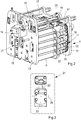
Figure 1 shows anammunition management system 1 according to the invention, disposed in anautomatic cannon 2. The ammunition management system comprises anammunition feed mechanism 3, also referred to as an ammunition feed device, and arotatable ammunition magazine 4 comprisingammunition 5, also referred to as ammunition shot or ammunition unit, wherein theammunition magazine 4 andammunition feed mechanism 3 are driven by acommon drive device 6. - The
ammunition magazine 4 is rotatably and detachably arranged directly on thebreech casing 7 of theautomatic cannon 2, below theammunition feed mechanism 3, via twofront rotation shafts 8 and two rear bolts 9. In therotatable ammunition magazine 4 there is arranged 10 - 50ammunition shots 5, preferably 15ammunition shots 5, ready to be fired from theautomatic cannon 2. When theautomatic cannon 2 is ready to fire,ammunition units 5 are fed from theammunition magazine 4 to thebreech casing 7 via theammunition feed device 3. - The
drive device 6 comprises anelectric motor 10 for driving theammunition magazine 4 and theammunition feed mechanism 3 via achain drive mechanism 11 disposed in the front andrear end walls ammunition magazine 4,Figure 2 . - The
ammunition management system 1 is arranged such that, when theammunition magazine 4 rotates anti-clockwise (viewed from the rear from the rear end wall 13), ammunition is fed from theammunition magazine 4 to thebreech casing 7 of the cannon. Clockwise rotation of theammunition magazine 4 is used for emptying ofammunition 5 and in the sorting of mixedammunition 5 in theammunition magazine 4. Adjacent to thechain drive mechanism 11 and theammunition feed mechanism 3 there is arranged adisengaging device 14, configured as a claw coupling, which makes it possible to rotate theammunition magazine 4 even when theammunition feed device 3 is stationary. By alternating between anti-clockwise and clockwise rotation of theammunition magazine 4, corresponding to feed-in/feed-out ofammunition 5 to/from theammunition feed device 3, it is possible to sort theammunition 5 in theammunition magazine 4 according to a preselected sorting program. - The
ammunition management system 1 comprises, apart from theammunition magazine 4, thefeed mechanism 3, thechain drive mechanism 11 and thedisengaging device 14, as well as anangle encoder 15 for registering the relative position of theammunition 5 in theammunition magazine 4. - The
ammunition magazine 4 is accessible in a simple and manageable manner, for example in connection with servicing or when theammunition magazine 4 needs to be emptied quickly, via two rear, releasable bolts 9 and twohandles 15, one on either side of theammunition magazine 4, with which theammunition magazine 4 can be lowered from a tilted-up position into a tilted-down position. - On the top side of the
ammunition magazine 4 there is arranged a protruding locking shaft coupled to a cardan joint, which has to be released before theammunition magazine 4 can be lowered. - The
ammunition magazine 4 withammunition 5,chain drive mechanism 11 andend walls beams 17, mounted between theend walls centre bracket 27 fitted to thebeams 17.End walls beams 17 are preferably made of aluminium or steel. - The
ammunition magazine 4 is driven by thechain drive mechanism 11 via twoseparate chains 18 disposed in thefront end wall 12 and in therear end wall 13 respectively. Thechains 18 are synchronized with one another via a number ofdrive shafts 19, which distribute the drive force from theelectric motor 10 to thechains 18. In total, sixdrive shafts 19 and sixchain wheels 20 are used, which ensures that thechains 18 are always synchronized with one another, even if one of thechains 18 is loose. There is also the possibility of adjusting thechains 18 manually via a chain-adjusting mechanism 21. The adjustment is made with the aid of adjustingscrews 22 connected to raisable andlowerable chain holders 23 on theend walls chain holder 23 is adjusted downwards in the height direction, the pretension decreases,Figure 3 . The degree of pretension is monitored via graduatedscales 24, arranged adjacent to achain holder 23. - The
ammunition 5 is transported around in theammunition magazine 4 via/onguide rods 25, which are coupled to thechain drive mechanism 11 via mounting pins 26. - The
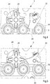
star wheels 28,Figure 4 , are mechanically synchronized with thechains 18 and will always correspond with the space (distance) between theammunition 5. The primary task of thestar wheels 28 is to feedammunition 5 to and from theammunition feed device 3 via spring-loadedpawls 29,Figure 4 and Figure 5 respectively. When theammunition 5 is fed to thebreech casing 7 of the cannon, thechains 18 rotate clockwise. Thestar wheels 28 press theammunition 5 against the spring-loadedpawls 29, which guideammunition 5 out from theammunition magazine 4 and onwards into theammunition feed device 3,Fig. 4 . - When the
ammunition 5 moves in the opposite direction, anti-clockwise, in theammunition magazine 4, the spring-loadedpawls 29 will be opened when theammunition 5 presses on thepawls 29, while theammunition 5, if there is anyammunition 5 in the feed-in position of theammunition feed device 3, can be fed back to a vacant position in theammunition magazine 4 unless thedecoupling device 14 is activated and prevents engagement,Figure 10 . - In the upper right-hand corner of the
rear end wall 13 there is ahatch 30 intended for manual loading/unloading ofammunition 5 to/from theammunition magazine 4. In the case of loading,ammunition 5 is introduced into theammunition magazine 4 via thehatch 30 into a position in which theflange 31 of the ammunition casing meets a stop in theend wall 13, whereafter theammunition unit 5 is pressed down into its intended position with the aid of a spring-loadedhook 32. By pulling on ablack handle 33 on theend wall 13, a spring-loadedejection mechanism 34 is activated, which ejects theammunition 5,Figure 6a and 6b . - The
ammunition magazine 4 and theammunition feed device 3 are driven by a drive unit comprising a planetary gear, aservomotor 10 having a built-in absolute angle encoder (internal angle encoder), and a mechanical brake. - The internal encoder in the
servomotor 10 is used to monitor theammunition magazine 4. If a power cut occurs, the mechanical brake will be activated, whereupon theammunition magazine 4 comes to a halt and is locked. It is nevertheless still possible to release the brake on condition that the power system is engaged, themagazine 4 being manually rotatable with the aid of a hand-operated crankshaft. - The
drive device 6 comprises anelectric motor 10 for driving theammunition magazine 4 and theammunition feed mechanism 3 via achain drive mechanism 11 disposed in the front andrear end walls ammunition magazine 4. Thechain mechanism 11 is driven via afront drive shaft 37 on thefront end wall 12. To thefront drive shaft 37 is also fitted aplanetary gear 35, to which the drive shaft of theelectric motor 10 is connected via afixed hub 36. Thehub 36 is mounted with a hexagon socket head screw, which is accessible via the mounting plate. Themotor 10 has two connections, an X1 connection for mains supply and an X2 connection for signal. - An
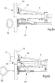
external angle encoder 38 is positioned on thefront end wall 12 of theammunition magazine 4, in which it is mounted on one of the drive shafts via a flexible damping device in order to minimize the effect of harmful shocks or vibrations. Theexternal encoder 38 is used only to verify that position of theammunition 5 which is given by the internal encoder in theservomotor 10. - In loading and unloading of
ammunition 5 to theammunition feed mechanism 3 from theammunition magazine 4, the movement of theammunition magazine 4 is synchronized with thestar wheel 28 in thechain drive mechanism 11 via three gearwheels in thedecoupling device 14. In the stated case, thedecoupling device 14 is always deactivated. - In order to enable reorganization and shifting of
ammunition 5 betweendifferent ammunition types 5 in theammunition magazine 4, theammunition feed device 3 must be able to be decoupled from theammunition magazine 4, i.e. thedecoupling device 14 must be activated, which is done with the aid of a solenoid, which controls thedecoupling device 14. - The
decoupling device 14 comprises a rear movable claw, which is activated once the solenoid has pressed back the claw into its rear position. In the event of a power cut, thedecoupling device 14 will remain deactivated due to pre-loaded helical springs which act on thedisengaging device 14 such that the movable claw of thedecoupling device 14 is kept pressed back in its rear position. Aninductive sensor 39,Figure 9 , directed towards the flange of the movable claw, signals when the claw changes position, i.e. when thedecoupling device 14 is activated. - The
ammunition magazine 4 is connected to theammunition feed device 3 via acoupling shaft 40,Figure 9 , configured with square cross section, which makes it impossible to connect themagazine 4 to theammunition feed device 3 incorrectly. In order to remove or lower theammunition magazine 4, theammunition magazine 4 must be decoupled from theammunition feed device 3. The decoupling can be realized by connecting an M8-screw to thecoupling shaft 40 and subsequently pulling on thecoupling shaft 40 such that it comes loose from the cardan joint in theammunition feed device 3.
Claims (8)
- Ammunition management system (1) for firing mixed ammunition (5) in an automatic cannon (2), comprising a rotatable ammunition magazine (4), comprising ammunition (5), a breech casing (7) and an ammunition feed device (3), wherein the ammunition management system (1) comprises a drive device (6) comprising an electric motor (10) for driving the ammunition magazine (4) and the ammunition feed device (3) via a chain drive mechanism (11) comprising two separate chains (18) disposed in a front and a rear end wall (12, 13), respectively, in the ammunition magazine (4), and star wheels (28) mechanically synchronized with the chains (18) to feed ammunition (5) to and from the ammunition feed device (3) via spring-loaded pawls (29), when the star wheels (28) press the ammunition (5) to the spring-loaded pawls (29), which guide ammunition (5) out from the ammunition magazine (4) and onwards to the ammunition device (3) or when the ammunition (5) moves in the opposite direction in the ammunition magazine (4), the spring-loaded pawls (29) opens when the ammunition (5) presses on the pawls (29), and in that the ammunition management system (1) also comprises a decoupling device (14) configured as a claw coupling for engagement and disengagement of the ammunition magazine (4) with respect to the ammunition feed device (3), so that ammunition (5) is movable between different positions in the ammunition magazine (4), wherein said star wheel (28) and chain drive mechanism (11) are synchronized when the decoupling device (14) is in a deactivated state .
- Ammunition management system (1) according to Claim 1, characterized in that the ammunition magazine (4) is rotatably disposed on the bottom side of the breech casing (7) in the vertical direction via two front rotation shafts (8) and two rear bolts (9), and via two handles (15), one on either side of the ammunition magazine (4), with which the ammunition magazine (4) can easily be lowered from a tilted-up position into a tilted-down position during servicing or during emptying of the magazine (4).
- Ammunition management system (1) according to Claim 1, characterized in that the ammunition magazine (4) is drivable via at least two separate chains (18), which are synchronized with one another via a system of drive shafts (19) and chain wheels (20), which drive shafts (19) and chain wheels (20) distribute the drive force between the chains (18) and ensure that the chains (18) are always synchronized with one another.
- Ammunition management system (1) according to Patent Claim 3, characterized in that the chains (18) are manually adjustable via a chain-adjusting mechanism (21), comprising adjusting screws (22) connected to raisable and lowerable chain holders (23) on the end walls (12), (13), arranged such that, when a chain holder (23) is adjusted upwards in the height direction, pretension in the chain (18) increases and, when a chain holder (23) is adjusted downwards in the height direction, the pretension decreases.
- Ammunition management system (1) according to Patent Claim 1, characterized in that the ammunition magazine (4) comprises a hatch (30) for manual feed-in and feed-out of ammunition (5) to the ammunition magazine (4) .
- Ammunition management system (1) according to Patent Claim 1, characterized in that the ammunition magazine (4) comprises an external angle encoder (38), configured to verify the position of the ammunition (5) in the ammunition magazine (4), wherein the angle encoder (38) is mounted on one of the drive shafts of the ammunition magazine (4) via a flexible damping device in order to minimize the effect of harmful shocks or vibrations.
- Ammunition management system (1) according to Patent Claim 1, characterized in that the ammunition magazine (4) is connected to the ammunition feed device (3) via a coupling shaft (40) configured with square cross section, which makes it impossible to connect the magazine (4) to the ammunition feed device (3) incorrectly.
- Method for sorting mixed ammunition (5) in an ammunition management system (1) according to any of claims 1-7, comprising the following steps:feeding of ammunition (5) from the ammunition magazine (4) to the ammunition feed device (3);decoupling of the ammunition magazine (4) from the ammunition feed device (3) via the decoupling device (14) ;rotation of the ammunition magazine (4) into a new position;coupling of the ammunition magazine (4) with the ammunition feed device (3); andfeeding of ammunition (5) from the ammunition feed device (3) into the new position in the ammunition magazine (4), where after said steps are repeated until all the ammunition (5) has been sorted into its predetermined positions.
Priority Applications (1)
| Application Number | Priority Date | Filing Date | Title |
|---|---|---|---|
| PL14859916T PL3066408T3 (en) | 2013-11-07 | 2014-11-03 | Management system and method for sorting mixed ammunition types |
Applications Claiming Priority (2)
| Application Number | Priority Date | Filing Date | Title |
|---|---|---|---|
| SE1300692A SE537591C2 (en) | 2013-11-07 | 2013-11-07 | Ammunition management system and method for sorting mixed ammunition types in a magazine |
| PCT/SE2014/000130 WO2015069167A1 (en) | 2013-11-07 | 2014-11-03 | Management system and method for sorting mixed ammunition types |
Publications (3)
| Publication Number | Publication Date |
|---|---|
| EP3066408A1 EP3066408A1 (en) | 2016-09-14 |
| EP3066408A4 EP3066408A4 (en) | 2017-03-22 |
| EP3066408B1 true EP3066408B1 (en) | 2018-09-26 |
Family
ID=53041817
Family Applications (1)
| Application Number | Title | Priority Date | Filing Date |
|---|---|---|---|
| EP14859916.0A Active EP3066408B1 (en) | 2013-11-07 | 2014-11-03 | Management system and method for sorting mixed ammunition types |
Country Status (8)
| Country | Link |
|---|---|
| US (1) | US9841247B2 (en) |
| EP (1) | EP3066408B1 (en) |
| KR (1) | KR102193501B1 (en) |
| CA (1) | CA2931780C (en) |
| PL (1) | PL3066408T3 (en) |
| SE (1) | SE537591C2 (en) |
| SG (1) | SG11201604476QA (en) |
| WO (1) | WO2015069167A1 (en) |
Families Citing this family (4)
| Publication number | Priority date | Publication date | Assignee | Title |
|---|---|---|---|---|
| SE541259C2 (en) | 2016-06-21 | 2019-05-21 | Bae Systems Bofors Ab | System and method for loading ammunition to a primary magazine in an automatic gun |
| CN108016618A (en) * | 2017-12-28 | 2018-05-11 | 深圳城际快机科技有限公司 | A kind of ammunition emitter and system |
| CN109029063B (en) * | 2018-07-16 | 2020-06-09 | 哈尔滨工业大学 | Device for continuously emitting light and small targets |
| TR2022003390A2 (en) * | 2022-03-07 | 2022-06-21 | Fnss Savunma Sistemleri Anonim Sirketi | ADJUSTABLE VERTICAL AMMUNITION LOADING MECHANISM |
Citations (22)
| Publication number | Priority date | Publication date | Assignee | Title |
|---|---|---|---|---|
| US1565836A (en) | 1924-10-01 | 1925-12-15 | Webster Thomas Herbert | Ammunition supply apparatus for gun turrets in which two or more guns are mounted |
| US2642688A (en) | 1950-12-06 | 1953-06-23 | Olin Ind Inc | Magazine-conversion unit for firearms |
| US3153368A (en) | 1957-06-03 | 1964-10-20 | Arthur J Stanton | Ammunition transfer mechanism |
| FR1492352A (en) | 1965-07-30 | 1967-08-18 | Oerlikon Buehrle Holding Ag | Ammunition store |
| FR2404827A1 (en) | 1977-09-28 | 1979-04-27 | Oerlikon Buehrle Ag | CARTRIDGE FEEDING DEVICE FOR AUTOMATIC FIREARMS |
| US4318331A (en) | 1979-07-06 | 1982-03-09 | Werkzeugmaschinenfabrik Oerlikon-Buhrle Ag | Automatic ammunition loading apparatus for an armored vehicle |
| FR2524136A1 (en) | 1982-03-27 | 1983-09-30 | Rheinmetall Gmbh | MECHANISM FOR SUPPLYING A DOUBLE-TUBE WEAPON WITH AMMUNITION |
| US4450750A (en) | 1981-10-20 | 1984-05-29 | Ares, Inc. | Dual shell feeding apparatus, with shell accumulators, for automatic guns |
| FR2707747A1 (en) | 1993-07-16 | 1995-01-20 | Ferretti Maurice | Device for making the magazine of a weapon irremovable. |
| US5440964A (en) | 1994-08-03 | 1995-08-15 | Martin Marietta Corporation | Ammunition magazine drive system |
| EP0694750A1 (en) | 1994-07-22 | 1996-01-31 | CTA International | Ammunition feeding system for small or medium calibre arms |
| DE19505349A1 (en) | 1995-02-17 | 1996-08-22 | Kuka Wehrtechnik Gmbh | Shell management system for tank munition magazine |
| WO1998025098A1 (en) | 1996-12-02 | 1998-06-11 | Bofors Ab | Method for stowing, transporting, and resupplying ammunition to artillery guns, and for a resupply vehicle designed for this purpose |
| US6272967B1 (en) | 1999-06-14 | 2001-08-14 | General Dynamics Armament Systems, Inc. | Modular ammunition storage and retrieval system |
| US20030089583A1 (en) | 2001-11-14 | 2003-05-15 | The Laitram Corporation | Compensation for shaft twist in the drive system of modular conveyor belts |
| WO2004025209A1 (en) | 2002-09-13 | 2004-03-25 | Denel Ltd | Ammunition feeding system |
| WO2009049721A1 (en) | 2007-10-17 | 2009-04-23 | Rheinmetall Waffe Munition Gmbh | Sensor-based function control of a weapon system |
| WO2009049710A1 (en) | 2007-10-17 | 2009-04-23 | Rheinmetall Waffe Munition Gmbh | Ammunition feeder |
| FR2925149A1 (en) | 2007-12-13 | 2009-06-19 | Cta Internat Sa | Semi-automatic ammunition feed magazine, has cells arranged along drive train following pitch delimited by spacing of axles of consecutive cells, where drive train drives set of cells in rotation |
| WO2012084669A1 (en) | 2010-12-21 | 2012-06-28 | Robert Bosch Gmbh | Portable power tool |
| US20120266748A1 (en) | 2009-10-21 | 2012-10-25 | Bae Systems Bofors Ab | Automatic charge magazine |
| JP2013078818A (en) | 2011-10-03 | 2013-05-02 | Tohnichi Mfg Co Ltd | Angle drive and torque equipment including the same |
Family Cites Families (13)
| Publication number | Priority date | Publication date | Assignee | Title |
|---|---|---|---|---|
| US2933981A (en) * | 1953-10-26 | 1960-04-26 | Paul E Anderson | Automatic repeating rocket launcher |
| US3376785A (en) * | 1965-06-30 | 1968-04-09 | Bofors Ab | Installation for loading the launching tubes of a depth-charge launcher |
| US3683743A (en) * | 1969-08-01 | 1972-08-15 | Stoner Eugen Morrison | Linkless cartridge feed system |
| US4434700A (en) * | 1982-01-04 | 1984-03-06 | General Electric Company | Automated ammunition mixer |
| DE3227214A1 (en) * | 1982-07-21 | 1984-01-26 | Rheinmetall GmbH, 4000 Düsseldorf | DRUM MAGAZINE FOR LARGE-SCALE AMMUNITION |
| FR2664966A1 (en) * | 1990-07-20 | 1992-01-24 | Creusot Loire | DEVICE FOR CONTROLLING THE AUTOMATIC LOADING OF A CANON. |
| FR2668253B1 (en) * | 1990-10-17 | 1994-09-30 | Creusot Loire | DEVICE FOR IDENTIFYING AND MONITORING THE AMMUNITION OF A SELF-LOADING FIREARMS AND METHOD FOR ITS IMPLEMENTATION. |
| DE59200441D1 (en) * | 1991-07-30 | 1994-10-06 | Contraves Ag | Device for feeding cartridges, mainly two different types of ammunition, to a Gatling gun. |
| EP0529289B1 (en) * | 1991-08-30 | 1995-04-26 | Oerlikon Contraves AG | Device for feeding a gatling gun with two different kinds of ammunition |
| NO960164D0 (en) * | 1996-01-15 | 1996-01-15 | Oeyvind Isachsen | Automatic ammunition type determination system |
| IT1399814B1 (en) * | 2010-04-27 | 2013-05-03 | Oto Melara Spa | METHOD AND SYSTEM OF LOADING AND DOWNLOADING BULLETS IN A MAGAZINE FOR FIREARMS. |
| DE102010016963A1 (en) * | 2010-05-17 | 2011-11-17 | Krauss-Maffei Wegmann Gmbh & Co. Kg | Weapon system, method for firing and detecting ammunition bodies |
| US20160231074A1 (en) * | 2013-11-22 | 2016-08-11 | Systems And Materials Research Corporation | Selective Ammunition Handling System |
-
2013
- 2013-11-07 SE SE1300692A patent/SE537591C2/en unknown
-
2014
- 2014-11-03 CA CA2931780A patent/CA2931780C/en active Active
- 2014-11-03 PL PL14859916T patent/PL3066408T3/en unknown
- 2014-11-03 US US15/101,180 patent/US9841247B2/en active Active
- 2014-11-03 SG SG11201604476QA patent/SG11201604476QA/en unknown
- 2014-11-03 WO PCT/SE2014/000130 patent/WO2015069167A1/en active Application Filing
- 2014-11-03 KR KR1020167015037A patent/KR102193501B1/en active IP Right Grant
- 2014-11-03 EP EP14859916.0A patent/EP3066408B1/en active Active
Patent Citations (22)
| Publication number | Priority date | Publication date | Assignee | Title |
|---|---|---|---|---|
| US1565836A (en) | 1924-10-01 | 1925-12-15 | Webster Thomas Herbert | Ammunition supply apparatus for gun turrets in which two or more guns are mounted |
| US2642688A (en) | 1950-12-06 | 1953-06-23 | Olin Ind Inc | Magazine-conversion unit for firearms |
| US3153368A (en) | 1957-06-03 | 1964-10-20 | Arthur J Stanton | Ammunition transfer mechanism |
| FR1492352A (en) | 1965-07-30 | 1967-08-18 | Oerlikon Buehrle Holding Ag | Ammunition store |
| FR2404827A1 (en) | 1977-09-28 | 1979-04-27 | Oerlikon Buehrle Ag | CARTRIDGE FEEDING DEVICE FOR AUTOMATIC FIREARMS |
| US4318331A (en) | 1979-07-06 | 1982-03-09 | Werkzeugmaschinenfabrik Oerlikon-Buhrle Ag | Automatic ammunition loading apparatus for an armored vehicle |
| US4450750A (en) | 1981-10-20 | 1984-05-29 | Ares, Inc. | Dual shell feeding apparatus, with shell accumulators, for automatic guns |
| FR2524136A1 (en) | 1982-03-27 | 1983-09-30 | Rheinmetall Gmbh | MECHANISM FOR SUPPLYING A DOUBLE-TUBE WEAPON WITH AMMUNITION |
| FR2707747A1 (en) | 1993-07-16 | 1995-01-20 | Ferretti Maurice | Device for making the magazine of a weapon irremovable. |
| EP0694750A1 (en) | 1994-07-22 | 1996-01-31 | CTA International | Ammunition feeding system for small or medium calibre arms |
| US5440964A (en) | 1994-08-03 | 1995-08-15 | Martin Marietta Corporation | Ammunition magazine drive system |
| DE19505349A1 (en) | 1995-02-17 | 1996-08-22 | Kuka Wehrtechnik Gmbh | Shell management system for tank munition magazine |
| WO1998025098A1 (en) | 1996-12-02 | 1998-06-11 | Bofors Ab | Method for stowing, transporting, and resupplying ammunition to artillery guns, and for a resupply vehicle designed for this purpose |
| US6272967B1 (en) | 1999-06-14 | 2001-08-14 | General Dynamics Armament Systems, Inc. | Modular ammunition storage and retrieval system |
| US20030089583A1 (en) | 2001-11-14 | 2003-05-15 | The Laitram Corporation | Compensation for shaft twist in the drive system of modular conveyor belts |
| WO2004025209A1 (en) | 2002-09-13 | 2004-03-25 | Denel Ltd | Ammunition feeding system |
| WO2009049721A1 (en) | 2007-10-17 | 2009-04-23 | Rheinmetall Waffe Munition Gmbh | Sensor-based function control of a weapon system |
| WO2009049710A1 (en) | 2007-10-17 | 2009-04-23 | Rheinmetall Waffe Munition Gmbh | Ammunition feeder |
| FR2925149A1 (en) | 2007-12-13 | 2009-06-19 | Cta Internat Sa | Semi-automatic ammunition feed magazine, has cells arranged along drive train following pitch delimited by spacing of axles of consecutive cells, where drive train drives set of cells in rotation |
| US20120266748A1 (en) | 2009-10-21 | 2012-10-25 | Bae Systems Bofors Ab | Automatic charge magazine |
| WO2012084669A1 (en) | 2010-12-21 | 2012-06-28 | Robert Bosch Gmbh | Portable power tool |
| JP2013078818A (en) | 2011-10-03 | 2013-05-02 | Tohnichi Mfg Co Ltd | Angle drive and torque equipment including the same |
Non-Patent Citations (1)
| Title |
|---|
| CTA INTERNATIONAL: "40mm CTWS Supporting UK France", 40TH ANNUAL ARMAMENT SYSTEMS GUNS-AMMUNITION-ROCKETS-MISSILES CONFERENCE AND EXHIBITION, 25 April 2005 (2005-04-25) - 28 April 2005 (2005-04-28), pages 59pp, XP055618068 |
Also Published As
| Publication number | Publication date |
|---|---|
| KR20160090307A (en) | 2016-07-29 |
| US9841247B2 (en) | 2017-12-12 |
| SG11201604476QA (en) | 2016-07-28 |
| KR102193501B1 (en) | 2020-12-21 |
| SE1300692A1 (en) | 2015-05-08 |
| CA2931780C (en) | 2017-12-19 |
| PL3066408T3 (en) | 2019-02-28 |
| US20160370136A1 (en) | 2016-12-22 |
| CA2931780A1 (en) | 2015-05-14 |
| SE537591C2 (en) | 2015-07-07 |
| EP3066408A1 (en) | 2016-09-14 |
| WO2015069167A1 (en) | 2015-05-14 |
| EP3066408A4 (en) | 2017-03-22 |
Similar Documents
| Publication | Publication Date | Title |
|---|---|---|
| EP3066408B1 (en) | Management system and method for sorting mixed ammunition types | |
| US7669512B2 (en) | Ammunition feed system with an automatic clutch | |
| US10066892B1 (en) | Modular automated mortar weapon for mobile applications | |
| EP2491330B1 (en) | Automatic charge magazine | |
| EP3472550B1 (en) | System and method for the reversible transfer of ammunition between a primary magazine and a secondary magazine in an automatic cannon | |
| KR101695173B1 (en) | Automatic bullet supplying apparatus for magazine of toy gun | |
| KR102630302B1 (en) | Device for feeding medium caliber ammunition with rotating plate | |
| DE3050016C2 (en) | Two stage grenade feeder with grenade feed path control | |
| EP2282157B1 (en) | Remote control cocking device for machine guns with a loading slide | |
| JPH09323833A (en) | Feeding and mounting device for tapered article | |
| EP3607261B1 (en) | Device for loading a barreled weapon with ammunition bodies | |
| KR20170014529A (en) | safety management system for Shooting Ranges with auto-transferring magazine | |
| JPS61143700A (en) | Monitor device for delay ignition for external force drivinggun | |
| US20220299301A1 (en) | Progressive ammunition press system | |
| RU2498195C1 (en) | Loader-transporter for self-propelled artillery-type weapon | |
| US548096A (en) | Machine-gun | |
| CN217877322U (en) | Screening arrangement bullet supply device and toy gun | |
| EP1216392B1 (en) | Ammunition handling system | |
| RU2243473C9 (en) | Salute cannon | |
| US7581484B1 (en) | Weapon system retention device | |
| PL222386B1 (en) | Automatic loading element of tank missiles |
Legal Events
| Date | Code | Title | Description |
|---|---|---|---|
| PUAI | Public reference made under article 153(3) epc to a published international application that has entered the european phase |
Free format text: ORIGINAL CODE: 0009012 |
|
| 17P | Request for examination filed |
Effective date: 20160607 |
|
| AK | Designated contracting states |
Kind code of ref document: A1 Designated state(s): AL AT BE BG CH CY CZ DE DK EE ES FI FR GB GR HR HU IE IS IT LI LT LU LV MC MK MT NL NO PL PT RO RS SE SI SK SM TR |
|
| AX | Request for extension of the european patent |
Extension state: BA ME |
|
| DAX | Request for extension of the european patent (deleted) | ||
| A4 | Supplementary search report drawn up and despatched |
Effective date: 20170221 |
|
| RIC1 | Information provided on ipc code assigned before grant |
Ipc: F41A 9/37 20060101ALI20170215BHEP Ipc: F41A 9/76 20060101AFI20170215BHEP Ipc: F41A 9/04 20060101ALI20170215BHEP |
|
| GRAP | Despatch of communication of intention to grant a patent |
Free format text: ORIGINAL CODE: EPIDOSNIGR1 |
|
| STAA | Information on the status of an ep patent application or granted ep patent |
Free format text: STATUS: GRANT OF PATENT IS INTENDED |
|
| INTG | Intention to grant announced |
Effective date: 20180504 |
|
| GRAS | Grant fee paid |
Free format text: ORIGINAL CODE: EPIDOSNIGR3 |
|
| GRAA | (expected) grant |
Free format text: ORIGINAL CODE: 0009210 |
|
| STAA | Information on the status of an ep patent application or granted ep patent |
Free format text: STATUS: THE PATENT HAS BEEN GRANTED |
|
| AK | Designated contracting states |
Kind code of ref document: B1 Designated state(s): AL AT BE BG CH CY CZ DE DK EE ES FI FR GB GR HR HU IE IS IT LI LT LU LV MC MK MT NL NO PL PT RO RS SE SI SK SM TR |
|
| REG | Reference to a national code |
Ref country code: GB Ref legal event code: FG4D |
|
| RIN1 | Information on inventor provided before grant (corrected) |
Inventor name: PALMLOEV, ULF Inventor name: TRULSSON, PER Inventor name: NILSSON, ANDREAS |
|
| REG | Reference to a national code |
Ref country code: CH Ref legal event code: EP |
|
| REG | Reference to a national code |
Ref country code: AT Ref legal event code: REF Ref document number: 1046516 Country of ref document: AT Kind code of ref document: T Effective date: 20181015 |
|
| REG | Reference to a national code |
Ref country code: IE Ref legal event code: FG4D |
|
| REG | Reference to a national code |
Ref country code: DE Ref legal event code: R096 Ref document number: 602014033164 Country of ref document: DE |
|
| REG | Reference to a national code |
Ref country code: NL Ref legal event code: MP Effective date: 20180926 |
|
| PG25 | Lapsed in a contracting state [announced via postgrant information from national office to epo] |
Ref country code: SE Free format text: LAPSE BECAUSE OF FAILURE TO SUBMIT A TRANSLATION OF THE DESCRIPTION OR TO PAY THE FEE WITHIN THE PRESCRIBED TIME-LIMIT Effective date: 20180926 Ref country code: BG Free format text: LAPSE BECAUSE OF FAILURE TO SUBMIT A TRANSLATION OF THE DESCRIPTION OR TO PAY THE FEE WITHIN THE PRESCRIBED TIME-LIMIT Effective date: 20181226 Ref country code: RS Free format text: LAPSE BECAUSE OF FAILURE TO SUBMIT A TRANSLATION OF THE DESCRIPTION OR TO PAY THE FEE WITHIN THE PRESCRIBED TIME-LIMIT Effective date: 20180926 Ref country code: GR Free format text: LAPSE BECAUSE OF FAILURE TO SUBMIT A TRANSLATION OF THE DESCRIPTION OR TO PAY THE FEE WITHIN THE PRESCRIBED TIME-LIMIT Effective date: 20181227 Ref country code: LT Free format text: LAPSE BECAUSE OF FAILURE TO SUBMIT A TRANSLATION OF THE DESCRIPTION OR TO PAY THE FEE WITHIN THE PRESCRIBED TIME-LIMIT Effective date: 20180926 Ref country code: FI Free format text: LAPSE BECAUSE OF FAILURE TO SUBMIT A TRANSLATION OF THE DESCRIPTION OR TO PAY THE FEE WITHIN THE PRESCRIBED TIME-LIMIT Effective date: 20180926 |
|
| REG | Reference to a national code |
Ref country code: LT Ref legal event code: MG4D Ref country code: NO Ref legal event code: T2 Effective date: 20180926 |
|
| PG25 | Lapsed in a contracting state [announced via postgrant information from national office to epo] |
Ref country code: LV Free format text: LAPSE BECAUSE OF FAILURE TO SUBMIT A TRANSLATION OF THE DESCRIPTION OR TO PAY THE FEE WITHIN THE PRESCRIBED TIME-LIMIT Effective date: 20180926 Ref country code: HR Free format text: LAPSE BECAUSE OF FAILURE TO SUBMIT A TRANSLATION OF THE DESCRIPTION OR TO PAY THE FEE WITHIN THE PRESCRIBED TIME-LIMIT Effective date: 20180926 Ref country code: AL Free format text: LAPSE BECAUSE OF FAILURE TO SUBMIT A TRANSLATION OF THE DESCRIPTION OR TO PAY THE FEE WITHIN THE PRESCRIBED TIME-LIMIT Effective date: 20180926 |
|
| PG25 | Lapsed in a contracting state [announced via postgrant information from national office to epo] |
Ref country code: CZ Free format text: LAPSE BECAUSE OF FAILURE TO SUBMIT A TRANSLATION OF THE DESCRIPTION OR TO PAY THE FEE WITHIN THE PRESCRIBED TIME-LIMIT Effective date: 20180926 Ref country code: EE Free format text: LAPSE BECAUSE OF FAILURE TO SUBMIT A TRANSLATION OF THE DESCRIPTION OR TO PAY THE FEE WITHIN THE PRESCRIBED TIME-LIMIT Effective date: 20180926 Ref country code: NL Free format text: LAPSE BECAUSE OF FAILURE TO SUBMIT A TRANSLATION OF THE DESCRIPTION OR TO PAY THE FEE WITHIN THE PRESCRIBED TIME-LIMIT Effective date: 20180926 Ref country code: RO Free format text: LAPSE BECAUSE OF FAILURE TO SUBMIT A TRANSLATION OF THE DESCRIPTION OR TO PAY THE FEE WITHIN THE PRESCRIBED TIME-LIMIT Effective date: 20180926 Ref country code: ES Free format text: LAPSE BECAUSE OF FAILURE TO SUBMIT A TRANSLATION OF THE DESCRIPTION OR TO PAY THE FEE WITHIN THE PRESCRIBED TIME-LIMIT Effective date: 20180926 Ref country code: IS Free format text: LAPSE BECAUSE OF FAILURE TO SUBMIT A TRANSLATION OF THE DESCRIPTION OR TO PAY THE FEE WITHIN THE PRESCRIBED TIME-LIMIT Effective date: 20190126 |
|
| PG25 | Lapsed in a contracting state [announced via postgrant information from national office to epo] |
Ref country code: SK Free format text: LAPSE BECAUSE OF FAILURE TO SUBMIT A TRANSLATION OF THE DESCRIPTION OR TO PAY THE FEE WITHIN THE PRESCRIBED TIME-LIMIT Effective date: 20180926 Ref country code: PT Free format text: LAPSE BECAUSE OF FAILURE TO SUBMIT A TRANSLATION OF THE DESCRIPTION OR TO PAY THE FEE WITHIN THE PRESCRIBED TIME-LIMIT Effective date: 20190126 Ref country code: SM Free format text: LAPSE BECAUSE OF FAILURE TO SUBMIT A TRANSLATION OF THE DESCRIPTION OR TO PAY THE FEE WITHIN THE PRESCRIBED TIME-LIMIT Effective date: 20180926 |
|
| REG | Reference to a national code |
Ref country code: DE Ref legal event code: R026 Ref document number: 602014033164 Country of ref document: DE |
|
| PLBI | Opposition filed |
Free format text: ORIGINAL CODE: 0009260 |
|
| 26 | Opposition filed |
Opponent name: CTA INTERNATIONAL Effective date: 20190620 |
|
| PG25 | Lapsed in a contracting state [announced via postgrant information from national office to epo] |
Ref country code: LU Free format text: LAPSE BECAUSE OF NON-PAYMENT OF DUE FEES Effective date: 20181103 Ref country code: MC Free format text: LAPSE BECAUSE OF FAILURE TO SUBMIT A TRANSLATION OF THE DESCRIPTION OR TO PAY THE FEE WITHIN THE PRESCRIBED TIME-LIMIT Effective date: 20180926 Ref country code: DK Free format text: LAPSE BECAUSE OF FAILURE TO SUBMIT A TRANSLATION OF THE DESCRIPTION OR TO PAY THE FEE WITHIN THE PRESCRIBED TIME-LIMIT Effective date: 20180926 |
|
| PLAX | Notice of opposition and request to file observation + time limit sent |
Free format text: ORIGINAL CODE: EPIDOSNOBS2 |
|
| REG | Reference to a national code |
Ref country code: IE Ref legal event code: MM4A |
|
| PG25 | Lapsed in a contracting state [announced via postgrant information from national office to epo] |
Ref country code: SI Free format text: LAPSE BECAUSE OF FAILURE TO SUBMIT A TRANSLATION OF THE DESCRIPTION OR TO PAY THE FEE WITHIN THE PRESCRIBED TIME-LIMIT Effective date: 20180926 Ref country code: IE Free format text: LAPSE BECAUSE OF NON-PAYMENT OF DUE FEES Effective date: 20181103 |
|
| PLBB | Reply of patent proprietor to notice(s) of opposition received |
Free format text: ORIGINAL CODE: EPIDOSNOBS3 |
|
| PG25 | Lapsed in a contracting state [announced via postgrant information from national office to epo] |
Ref country code: MT Free format text: LAPSE BECAUSE OF NON-PAYMENT OF DUE FEES Effective date: 20181103 |
|
| PG25 | Lapsed in a contracting state [announced via postgrant information from national office to epo] |
Ref country code: MK Free format text: LAPSE BECAUSE OF NON-PAYMENT OF DUE FEES Effective date: 20180926 Ref country code: HU Free format text: LAPSE BECAUSE OF FAILURE TO SUBMIT A TRANSLATION OF THE DESCRIPTION OR TO PAY THE FEE WITHIN THE PRESCRIBED TIME-LIMIT; INVALID AB INITIO Effective date: 20141103 Ref country code: CY Free format text: LAPSE BECAUSE OF FAILURE TO SUBMIT A TRANSLATION OF THE DESCRIPTION OR TO PAY THE FEE WITHIN THE PRESCRIBED TIME-LIMIT Effective date: 20180926 |
|
| REG | Reference to a national code |
Ref country code: DE Ref legal event code: R100 Ref document number: 602014033164 Country of ref document: DE |
|
| PLCK | Communication despatched that opposition was rejected |
Free format text: ORIGINAL CODE: EPIDOSNREJ1 |
|
| PLBN | Opposition rejected |
Free format text: ORIGINAL CODE: 0009273 |
|
| STAA | Information on the status of an ep patent application or granted ep patent |
Free format text: STATUS: OPPOSITION REJECTED |
|
| 27O | Opposition rejected |
Effective date: 20210112 |
|
| REG | Reference to a national code |
Ref country code: AT Ref legal event code: UEP Ref document number: 1046516 Country of ref document: AT Kind code of ref document: T Effective date: 20180926 |
|
| PGFP | Annual fee paid to national office [announced via postgrant information from national office to epo] |
Ref country code: PL Payment date: 20221018 Year of fee payment: 9 Ref country code: BE Payment date: 20221128 Year of fee payment: 9 |
|
| P01 | Opt-out of the competence of the unified patent court (upc) registered |
Effective date: 20230526 |
|
| PGFP | Annual fee paid to national office [announced via postgrant information from national office to epo] |
Ref country code: GB Payment date: 20231127 Year of fee payment: 10 |
|
| PGFP | Annual fee paid to national office [announced via postgrant information from national office to epo] |
Ref country code: TR Payment date: 20231024 Year of fee payment: 10 Ref country code: NO Payment date: 20231129 Year of fee payment: 10 Ref country code: IT Payment date: 20231122 Year of fee payment: 10 Ref country code: FR Payment date: 20231127 Year of fee payment: 10 Ref country code: DE Payment date: 20231129 Year of fee payment: 10 Ref country code: CH Payment date: 20231202 Year of fee payment: 10 Ref country code: AT Payment date: 20231019 Year of fee payment: 10 |
|
| PGFP | Annual fee paid to national office [announced via postgrant information from national office to epo] |
Ref country code: PL Payment date: 20231018 Year of fee payment: 10 Ref country code: BE Payment date: 20231127 Year of fee payment: 10 |