EP3055590B1 - Shift-by-wire betätigungseinrichtung und verfahren zur auswahl von fahrstufen - Google Patents
Shift-by-wire betätigungseinrichtung und verfahren zur auswahl von fahrstufen Download PDFInfo
- Publication number
- EP3055590B1 EP3055590B1 EP14766436.1A EP14766436A EP3055590B1 EP 3055590 B1 EP3055590 B1 EP 3055590B1 EP 14766436 A EP14766436 A EP 14766436A EP 3055590 B1 EP3055590 B1 EP 3055590B1
- Authority
- EP
- European Patent Office
- Prior art keywords
- signal
- enable
- blocking
- transmission
- information
- Prior art date
- Legal status (The legal status is an assumption and is not a legal conclusion. Google has not performed a legal analysis and makes no representation as to the accuracy of the status listed.)
- Active
Links
Images

Classifications
-
- F—MECHANICAL ENGINEERING; LIGHTING; HEATING; WEAPONS; BLASTING
- F16—ENGINEERING ELEMENTS AND UNITS; GENERAL MEASURES FOR PRODUCING AND MAINTAINING EFFECTIVE FUNCTIONING OF MACHINES OR INSTALLATIONS; THERMAL INSULATION IN GENERAL
- F16H—GEARING
- F16H61/00—Control functions within control units of change-speed- or reversing-gearings for conveying rotary motion ; Control of exclusively fluid gearing, friction gearing, gearings with endless flexible members or other particular types of gearing
- F16H61/22—Locking of the control input devices
-
- B—PERFORMING OPERATIONS; TRANSPORTING
- B60—VEHICLES IN GENERAL
- B60R—VEHICLES, VEHICLE FITTINGS, OR VEHICLE PARTS, NOT OTHERWISE PROVIDED FOR
- B60R25/00—Fittings or systems for preventing or indicating unauthorised use or theft of vehicles
- B60R25/002—Locking of control actuating or transmitting means
- B60R25/003—Locking of control actuating or transmitting means locking of control actuating means
- B60R25/007—Locking of control actuating or transmitting means locking of control actuating means of hand actuated control means
-
- B—PERFORMING OPERATIONS; TRANSPORTING
- B60—VEHICLES IN GENERAL
- B60R—VEHICLES, VEHICLE FITTINGS, OR VEHICLE PARTS, NOT OTHERWISE PROVIDED FOR
- B60R25/00—Fittings or systems for preventing or indicating unauthorised use or theft of vehicles
- B60R25/20—Means to switch the anti-theft system on or off
- B60R25/25—Means to switch the anti-theft system on or off using biometry
- B60R25/252—Fingerprint recognition
-
- F—MECHANICAL ENGINEERING; LIGHTING; HEATING; WEAPONS; BLASTING
- F16—ENGINEERING ELEMENTS AND UNITS; GENERAL MEASURES FOR PRODUCING AND MAINTAINING EFFECTIVE FUNCTIONING OF MACHINES OR INSTALLATIONS; THERMAL INSULATION IN GENERAL
- F16H—GEARING
- F16H59/00—Control inputs to control units of change-speed- or reversing-gearings for conveying rotary motion
- F16H59/02—Selector apparatus
- F16H59/08—Range selector apparatus
- F16H2059/081—Range selector apparatus using knops or discs for rotary range selection
-
- F—MECHANICAL ENGINEERING; LIGHTING; HEATING; WEAPONS; BLASTING
- F16—ENGINEERING ELEMENTS AND UNITS; GENERAL MEASURES FOR PRODUCING AND MAINTAINING EFFECTIVE FUNCTIONING OF MACHINES OR INSTALLATIONS; THERMAL INSULATION IN GENERAL
- F16H—GEARING
- F16H59/00—Control inputs to control units of change-speed- or reversing-gearings for conveying rotary motion
- F16H59/02—Selector apparatus
- F16H59/0278—Constructional features of the selector lever, e.g. grip parts, mounting or manufacturing
-
- F—MECHANICAL ENGINEERING; LIGHTING; HEATING; WEAPONS; BLASTING
- F16—ENGINEERING ELEMENTS AND UNITS; GENERAL MEASURES FOR PRODUCING AND MAINTAINING EFFECTIVE FUNCTIONING OF MACHINES OR INSTALLATIONS; THERMAL INSULATION IN GENERAL
- F16H—GEARING
- F16H61/00—Control functions within control units of change-speed- or reversing-gearings for conveying rotary motion ; Control of exclusively fluid gearing, friction gearing, gearings with endless flexible members or other particular types of gearing
- F16H61/18—Preventing unintentional or unsafe shift, e.g. preventing manual shift from highest gear to reverse gear
Definitions
- the present invention relates to a shift-by-wire actuator and a method for selecting driving levels of a motor vehicle transmission.
- a shift-by-wire actuator is, for example, in the published patent application DE 10 2007 037 706 A1 disclosed.
- the previously known actuating device comprises a translationally movable sliding element for manual switching of the motor vehicle transmission, wherein the sliding element has a grip on which a thumbwheel is provided for the manual selection of driving steps of the motor vehicle transmission.
- the translational displacement property of the sliding element is used for a motor vehicle automatic transmission usual tip alley, while the arranged on the handle knurled wheel for an automatic lane. By means of the knurled wheel, a selection of at least the forward drive or drive D, reverse drive R and neutral or neutral N travel ranges is thus possible.
- the parking brake position P can be engaged via an additional actuator.
- the previously known actuating device further comprises a shift lock device, by means of which an inadvertent selection of one of the speed steps R and D from the parking lock position P is to be prevented.
- a shift lock device by means of which an inadvertent selection of one of the speed steps R and D from the parking lock position P is to be prevented.
- For deactivating the parking lock P or for selecting one of the speed ranges R and D from the Parking lock position P is initially an operation of the brake and a simultaneous actuation of the actuator necessary. Alternatively, it is provided to release the parking brake only by means of the additional parking brake actuator.
- a generic shift-by-wire actuator is from the US 2003/0029261 A1 known.
- the present invention provides an improved shift-by-wire actuator is provided, which meets the ever growing constructive and ergonomic requirements and safety requirements by at least an unintended selection of driving levels, in particular starting from another gear as the parking lock position is reliably prevented.
- the proposed actuating device is provided in particular for a motor vehicle automatic transmission or a motor vehicle automatic transmission.
- the proposed actuating device comprises an actuating field in which at least one scrolling surface for selecting one of the driving steps and a release button, which transmits an enabling signal based on an actuation, are arranged.
- at least the driving steps forward driving mode D, neutral position N and reverse driving mode R can be selected via the scroll surface.
- the driving position parking position P is additionally selectable via the scroll surface.
- at least one other than the aforementioned driving levels can be selected via the scroll surface.
- a scrolling surface is preferably a movable operating surface, which is movable back and forth.
- the scroll surface is formed by a user interface of a scroll wheel rotatable about a rotation axis, wherein the rotatability of the scroll wheel or the user interface is preferably limited or unlimited in at least one direction.
- the scrolling surface is preferably formed by a stationary operating surface, in particular a touch sensor surface, on which an operator of the actuating device for selecting a driving step must slide his finger one or more times backwards or forwards in accordance with a scrolling movement.
- the actuating device is characterized in that the scrolling surface and the release button are coupled to one another via a blocking and release device in such a way that each shift-effective selection of a driving step by means of the scrolling surface activates a release signal by actuating the release button for release by the blocking and releasing device based on the Release signal required.
- the selection is switching-active when the selection of the at least one driving step by means of the scroll surface has a corresponding switching of the motor vehicle transmission result.
- actuating device in contrast to the known prior art, a shift-effective selection of at least one gear from the selectable gear levels locked until receiving an enable signal, whereby accidental operation of a speed selector element and a concomitant selection of other than the current gear can be reliably avoided.
- a release signal by pressing a release button is required in contrast to the prior art first.
- a smaller, space-saving actuator can be provided in departure from conventional actuators by a completely different embodiment of the selector lever, in particular by dispensing with a conventional selector lever rod, which establishes a connection of a freely accessible actuator for the user to the mechanics or electronics for transmitting the selected gear.
- the actuating device further comprises a sensor device, which has at least one signal generator and signal receiver.
- a sensor device which has at least one signal generator and signal receiver.
- more than one signal generator or a signal receiver may be provided, whereby a signal accuracy can be increased.
- the signal generator is coupled to the scroll surface in such a way that an actuation of the scroll surface leads to a signal of the signal transmitter triggered by a signal indicating a selected drive level.
- an actuation of the scroll surface can be detected and an information derived from the actuation of the scroll surface information can be transmitted via a selected gear by means of a signal.
- a conventional electronic sensors can be used.
- a position sensor based on Hall sensors can be used in combination with the preferred scroll wheel, wherein the signal generator, which may be a permanent magnet or electromagnet, is fixedly connected to the scroll wheel.
- the signal generator which may be a permanent magnet or electromagnet
- a conventional electronic touch sensor can be used in combination with the preferred touch sensor surface.
- the selectable speed levels are determined via the scroll surface such that an identification of the selected speed level in response to an operation of the scroll surface is possible.
- the detected and transmitted by the sensor device information about the selected gear causes a selected driving gear corresponding switching of the motor vehicle transmission.
- the information about the selected gear can be done by means of a sensor signal from the sensor device to a transmission control unit, which causes a corresponding switching of the motor vehicle transmission based on the transmitted information with the sensor signal on the selected gear.
- a further control unit or an evaluation unit may be interposed, which first processes the sensor signal or the information transmitted with the sensor signal via the selected drive stage, for example, evaluates it and then transmits it further.
- the blocking and enabling device is arranged to block and release a transmission of a signal having information about a selected driving step, wherein the blocking and enabling device can be transmitted in a transmission path via which the signal with the information about the selected driving state can be transmitted and which of the scrolling surface extends to the motor vehicle transmission, is interposed and blocks the transmission of the signal with the information on the selected gear at least until the release signal.
- the manner of signal transmission can be varied and is not essential to the present invention. It is conceivable, for example, an electrical, inductive or optical signal transmission or a combination thereof with corresponding intermediate interfaces.
- the transmission path preferably comprises at least line and / or air routes, via which at least a transmission of the signal with the information about the selected drive level takes place.
- an air gap is present between the signal transmitter and the signal receiver, via which information originating from the signal generator can be transmitted via the selected drive stage by means of a signal to the signal receiver or can be tapped by the signal receiver.
- a signal line for example an electrical connection line as part of the transmission path for the information about the selected driving position, can also be considered.
- the signal line already starts from the signal generator.
- all devices or devices between the scroll surface and the motor vehicle transmission are preferably encompassed by the transmission path process the signal with the information about the selected drive level such as evaluate, transmit, pass or the like.
- the apparatus may also include or house signal lines as a line for transmitting a signal having the information about the selected gear.
- the blocking and enabling device is set up to block a transmission of a signal with the information about the selected drive stage in a region of the transmission path, which may comprise at least one air and / or line route and / or at least one device or device and release.
- the blocking and releasing means by means of a switching element which interrupts and closes the line, a shielding element, which is introduced into the air route and removable and shields the transmission of the signal with the information on the selected gear or a blocking program for one of the devices Be configured or devices controlling software that allow at least in each case in response to the triggered by an actuation of the release key enable signal transmission of the signal with the information on the selected gear level or release.
- actuating device in contrast to the prior art, a transmission of a signal with a selected gear after selecting the gear until the reception of a release signal is disabled, whereby an unintentional operation of a speed selector element and a concomitant selection of other than the current gear can be reliably avoided.
- an actuation of a release button is first required, whereby the release signal deducted and only based on a transmission of the signal with the information is enabled or possible via the selected gear.
- a smaller, space-saving actuator can be provided.
- the release button is arranged to transmit a blocking signal in response to a further actuation. Furthermore, the blocking and enabling device is set up to block a transmission of the signal with the information on the selected gear stage on or after receipt of the blocking signal until receipt of a subsequent release signal.
- the release key is not continuously operable during gear selection to enable transmission of a signal having information about the selected gear.
- a single actuation of the release button is sufficient to place the actuator in a release state in which at least one transmission of the signal with the information on the selected gear is performed. Only after repeated or renewed actuation of the release button, the actuator is based on the remote from the release button lock signal in a locked state, in which a transmission of the signal is blocked with the information about the selected gear.
- the inhibit and enable device is arranged, in the absence of a blocking signal, to block transmission of the signal with the information on the selected drive level after a predetermined period of time has elapsed after receipt of the enable signal or after the end of actuation of the scroll area for selecting one of the drive levels.
- the locking and releasing device comprises a movable blocking element, which is in an initial state in engagement with a scroll wheel forming scroll wheel for blocking rotational movement of the scroll wheel and is arranged based on the release signal the engagement for releasing the rotational movement of the scroll wheel to solve.
- the locking and releasing device comprises an electromagnetic actuator with a movable locking element forming or supporting retractable and retractable armature which engages in an extended state engagement with the scroll wheel for blocking the rotational movement of the scroll wheel and in a retracted state, the rotational movement of the scroll wheel releases.
- the electromagnetic actuator is in the deenergized state in the de-energized state and in the deenergized retracted state in an energized state which is initiated based on the operation of the release button.
- An energy consumption of the actuator can be kept low compared to a reverse design of the electromagnetic actuator.
- the control of the electromagnetic actuator may preferably be effected via a control device which is coupled to the release button and the electromagnetic actuator.
- the release button may be formed as a pressure switch, the energizing upon actuation of the electromagnetic actuator Circuit closes and opens the circuit in non-operation, whereby the electromagnetic actuator is de-energized.
- the locking and releasing device preferably comprises a mechanism extending from the release button to the movable locking element, which upon actuation of the release button, automatically engages the movable locking element in the non-engaged state, which is in a release state and in the non-operation or release of the release button Engaging state spends.
- a cheaper actuator can be provided.
- the scroll wheel is designed monostable or multistable.
- monostable means such a design of the scroll wheel that the scroll wheel can be moved between two end positions with an idle position therebetween, whereby the scroll wheel automatically returns to the rest position after reaching an end position.
- the respective end positions are assigned, depending on a selected output driving step, to a next driving step adjacent to the order.
- the predetermined order of the driving stages may be P, R, N, D, the last selected starting driving gear being the driving gear N and the respective end positions provided in the opposite rotational direction of the scrolling wheel, the driving wheels R adjacent to the starting driving gear N according to the aforementioned ranking order or D are.
- the actuating device has a control device or is coupled to one which automatically assigns to the respective end positions of the scroll wheel a drive step immediately following the last selected drive step according to a predetermined sequence of the drive steps.
- the actuating device has a locking device coupled to the scroll wheel, which provides one of the selectable speed levels corresponding number of locking positions for the scroll wheel.
- the scroll wheel is infinitely rotatable in at least one of the two opposite directions of rotation.
- the Rastierinnate it may be a usual, equipped with shift-by-wire actuators Rastier pleasing.
- the monostable or multi-stable design of the scroll wheel allows haptic feedback for the user when selecting the appropriate gear.
- the scroll surface and the release button are arranged such that a particular simultaneous operation of these two components by means of only one hand of a user is possible.
- the proposed actuator can be operated in a simple manner.
- the release button is provided for actuation by the thumb and the scroll surface for actuation by another finger, more preferably by the index or middle finger. The operability of the actuator can be further simplified.
- the actuating field comprises a palm rest, which has or forms the release button.
- the release button is disposed in a recess of the palm rest or on a surface of the palm rest.
- the palm rest may preferably comprise a sensor surface which upon contact by the user deposits the corresponding release signal.
- the palm rest itself forms the release button. More preferably, the palm rest itself is designed as a push-button element.
- the release button is formed by a fingerprint sensor for identifying a user of the actuator, wherein the release button is coupled to an identification device, which performs a comparison of a captured via the release button fingerprint with a stored in the identification device or stored fingerprint and if coincident, sends a signal to the inhibit and enable device to enable the transmission of the signal with the information about the selected drive level through the inhibit and enable device.
- that of the release button corresponds to the identification device transmitted fingerprint already a release signal, provided that the detected fingerprint matches the stored fingerprint. Thereby, a switching of the motor vehicle transmission by an unauthorized user can be prevented, whereby the actuator is used in combination with a motor vehicle theft protection.
- the actuating device comprises a display device for displaying at least the selected driving speed.
- the display device is set up in addition to the display of the selectable driving levels, wherein the currently selected driving gear is offset from the selectable driving levels in terms of color or brightness intensity. More preferably, the display device is arranged in the operating field.
- the display device is directly or indirectly connected to the blocking and enabling device in such a way that information about the selected drive level can be displayed via the display device.
- An immediate connection to the lock and release device requires a connection without any further intermediary devices or devices.
- An indirect connection requires at least one intermediary device or device, such as a controller, that processes a signal with the information about the selected drive level.
- a method for selecting driving steps of a motor vehicle transmission by means of a shift-by-wire actuator of the type described above comprises a step of actuating a release button for issuing at least one enable signal to enable a transmission of a signal having information about a selected gear level based on an operation of a scroll surface by means of which a selection of one of the gear levels is feasible in response to its actuation.
- the method comprises a step of selecting a driving step by operating the scrolling surface.
- the method further comprises a step of transmitting the signal with information about the selected gear after selecting the gear.
- the method comprises a subsequent step of disabling transmission of a signal having information about a selected drive stage until receipt of an enable signal.
- the scroll wheel 7 In a multistable embodiment of the scroll wheel 7 this is rotatable in a plurality of detent positions in opposite directions of rotation, wherein the scroll wheel 7 either unlimited freely rotatable or after reaching an extreme according to a speed step sequence drive stage reaches an end position.
- the scroll wheel 7 is coupled to a sensor device (not shown) for detecting a rotational movement of the scroll wheel 7 or the scroll surface 6.
- the detection of the rotational movement of the scroll wheel 7 or the scroll surface 6 can be done in a conventional manner optically, magnetically, in particular Hall sensor based or other commonly known manner.
- a predetermined rotational travel of the scroll wheel 7 or of the scroll surface 6 is in each case assigned to a selectable driving step.
- the scroll wheel 7 can thereby select, for example, one of the drive positions parking position P, reverse drive mode R, neutral position N or drive or forward drive mode D.
- the driving position parking position P is not necessarily selectable by means of an actuation of the scroll surface 6 and the scroll wheel 7.
- the parking position P can be activated and / or deactivated, for example, by means of an additional actuating element.
- the actuating device 1 has a display device 12 in the operating field 4.
- the display device 12 shows on the one hand the selectable speed levels and on the other by color offset to the other speed levels the selected via the scroll surface 6 current gear on.
- the display device 12 may be a lighted by illuminating display unit, for example, an LED display or a programmable display, by means of which a variable, needs-based adjustment of the display is possible.
- the display device 12 does not necessarily have to be arranged in the operating field 4.
- the display device 12 may be provided according to a further preferred embodiment in a fitting in the field of view of a motor vehicle driver. An additional arrangement of a display device for displaying the selectable and selected drive level is also conceivable for the display device 12.
- the palm rest 10 is arranged and fixed to the extent that a user of the actuator his hand or his palm rest comfortably on the palm rest 10 and reach the actuators in the actuating surface 4, so at least the scroll surface 6 and the release button 8 with his fingers and press.
- the palm rest 10 is provided as a replaceable module for the actuating device 1 in order to be able to provide a palm rest adapted to the size of a user's hand with the actuating device 1.
- the scrolling surface 6 and the release button 8 are arranged in the operation field 4 such that the release button 8 is operable by means of a thumb of a user's hand and the scrolling surface 6 by means of a pointing or middle finger of the user's hand.
- the release button 8 has a recess 14 corresponding to the thumb surface, in order to allow a pleasant operating feeling and a pleasant placement of the thumb on the release button.
- a signal-triggering key element 16 is arranged for actuation by the thumb.
- the key element 16 may be, for example, a pushbutton or a sensor key. Upon actuation of the key element 16, a release signal is issued by the release button 8 to a locking and releasing device, which is not shown.
- the locking and releasing device on an electric drive with an extendable and retractable anchor may be, for example, an electromagnetic actuator.
- the armature is extended in a de-energized state of the electric drive and is in the extended state in engagement with the scroll wheel 7 for blocking a rotational movement desselbigen.
- the scroll wheel 7 at least one engagement for the anchor.
- the armature In an energized state of the electric drive, the armature is retracted and releases the rotational movement of the scroll wheel 7.
- the retracted state of the armature is caused by actuation of the release button 8 and the release signal.
- the release button 8 is coupled to the lock and release device such that, based on the release signal issued by the release button 8 after actuation, a circuit of the electric drive for energizing the same is closed.
- the release button 8 may be designed as a switch which is directly connected to the circuit of the electric drive.
- the release button 8 simultaneously forms the blocking and release device. During an operation of the release button 8, the circuit is thus closed, whereas a release of the release button 8 or a non-operation leads to a de-energized state of the electric drive.
- the locking and releasing means may comprise a mechanism capable of transmitting a locking element equivalent to the armature to a disengaged and disengaged engagement state based on an operation of the release button 8.
- a gear mechanism connected to the blocking element or a linkage connected to the blocking element or a combination thereof can be provided.
- the release button 8 can be configured as a push button, the actuation of which acts directly by force transmission of the force acting on the release button 8 actuating force on the mechanism so that the locking element from the locked state in the release state and when not operated again in the blocking state can be brought.
- the release button 8 may be configured as a sensor or touch button, which is connected to a control device, which may be part of the locking and releasing device. Based on an actuation of the release button 8, the control device transmits a signal closing or opening the circuit of the electric drive to a switch arranged in the circuit, which is a component of the blocking and release device.
- the non-illustrated locking and releasing device is coupled to the scroll surface 6 or the scroll wheel 7 or alternatively with a sensor device, not shown, such that at least one switching effective transmission of a signal with information about the selected gear until the release signal Is blocked.
- the sensor device is a Hall sensor-based position sensor system with a permanent magnet or electromagnet as signal transmitter, which is coupled to the scroll surface 6 or the scroll wheel 7, and one or more Hall sensors as signal receiver, for example, stationary are connected to the housing 2.
- the signal generator is stationarily connected to the scroll wheel 7 and is forcibly moved by means of a rotary movement of the scroll wheel 7.
- the signal generator is matched to the signal receiver such that a predetermined magnetic field change by rotational movement of the signal generator corresponds to a predetermined selectable gear.
- the signal receiver transmits upon rotation of the scroll wheel 7 a signal corresponding to the detected magnetic field change, wherein the magnetic field change corresponds to an information about the selected drive stage.
- the signal transmitted by the sensor device can be evaluated by a control device, which causes a switching of the motor vehicle transmission based on the information transmitted with the signal about the selected driving step.
- the blocking and releasing device is connected to a circuit of the signal generator forming electromagnet, which is coupled to the scroll surface 6 and the scroll wheel 7.
- the electrical connection of the electromagnet as a signal generator in or on the scroll wheel 7 or the scroll surface 6 is ensured for example via a sliding contact in a bearing point of the scroll wheel 7.
- the circuit is closed, allowing interaction between the signal generator and the signal receiver to identify a selected gear based on a magnetic field change and a signal based thereon with the information on the selected gear ,
- the release signal is transmitted according to a preferred embodiment for a period corresponding to the duration of the actuation or after actuation of the release button 8.
- the locking and releasing means is arranged, in response to a further actuation of the release button 8, which follows an operation for triggering the release signal, a disable signal for inhibiting the transmission of the signal with the information on the selected drive stage until a to transmit further enable signal.
- the inhibit and enable device is arranged, in the absence of such a blocking signal, to block the transmission of the signal with the information on the selected gear after a predetermined time after receipt of the enable signal. This can be reliably ensured that an unintentional rotation of the scroll surface 6 does not occur after a predetermined time to a switching-effective signal transmission associated with a switching of the motor vehicle transmission.
- FIG. 2 shows a side view of the FIG. 1 shown actuator 1.
- FIG. 2 illustrates an approximate computer mouse-like shape of the actuator 1, which allows convenient storage of a user's hand on the palm rest 10 and a simple and convenient operation of the actuator 1.
- the sensor device, not shown, as well as the locking and releasing device can be arranged to save space in the area below the operating field 4 or on one of the actuating field 4 side facing away from the housing 2 or within the housing 2.
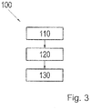
- FIG. 3 shows a flowchart of a method for selecting driving levels of a motor vehicle transmission by means of a shift-by-wire actuator according to a preferred embodiment. The method is illustrated below with reference to the above-described actuator 1.
- the release button 8 is actuated to trigger an enable signal that enables a transmission of a signal with an information effected via a selected gear in the direction of the motor vehicle transmission.
- the lock and release device releases the lock based on the actuation of the release button 8 and the associated enable signal, and permits transmission of a signal having information about a selected drive level.
- a step 120 the selection of the desired gear by pressing the scroll surface 6, whereby a signal with the information about the selected gear is delivered in the direction of the motor vehicle transmission, to cause a corresponding switching of the motor vehicle transmission.
- a step 130 the transmission of a signal with information about a selected drive level is disabled again.
- this can be fixed in place, for example, by opening a circuit which is provided for the power supply of an electric drive to block a rotary movement of the scroll surface 6 or the scroll wheel 7 or an electromagnet, which is fixedly coupled as a signal generator to the scroll surface 6 or the scroll wheel 7 is, or in another derivable from the above-described preferred embodiments manner.
- an unintentional shift-effective selection of a driving step can be prevented by unintentional actuation of the scrolling surface.
Landscapes
- Engineering & Computer Science (AREA)
- General Engineering & Computer Science (AREA)
- Mechanical Engineering (AREA)
- Human Computer Interaction (AREA)
- Mechanical Control Devices (AREA)
- Arrangement Or Mounting Of Control Devices For Change-Speed Gearing (AREA)
- Instrument Panels (AREA)
- Control Of Transmission Device (AREA)
- Lock And Its Accessories (AREA)
- Gear-Shifting Mechanisms (AREA)
Applications Claiming Priority (2)
| Application Number | Priority Date | Filing Date | Title |
|---|---|---|---|
| DE201310220404 DE102013220404A1 (de) | 2013-10-10 | 2013-10-10 | Shift-by-wire Betätigungseinrichtung und Verfahren zur Auswahl von Fahrstufen |
| PCT/EP2014/069241 WO2015051960A1 (de) | 2013-10-10 | 2014-09-10 | Shift-by-wire betätigungseinrichtung und verfahren zur auswahl von fahrstufen |
Publications (2)
| Publication Number | Publication Date |
|---|---|
| EP3055590A1 EP3055590A1 (de) | 2016-08-17 |
| EP3055590B1 true EP3055590B1 (de) | 2017-08-16 |
Family
ID=51542349
Family Applications (1)
| Application Number | Title | Priority Date | Filing Date |
|---|---|---|---|
| EP14766436.1A Active EP3055590B1 (de) | 2013-10-10 | 2014-09-10 | Shift-by-wire betätigungseinrichtung und verfahren zur auswahl von fahrstufen |
Country Status (8)
| Country | Link |
|---|---|
| US (1) | US10352440B2 (enExample) |
| EP (1) | EP3055590B1 (enExample) |
| JP (1) | JP6389878B2 (enExample) |
| KR (1) | KR102305157B1 (enExample) |
| CN (1) | CN105637261B (enExample) |
| DE (1) | DE102013220404A1 (enExample) |
| ES (1) | ES2642833T3 (enExample) |
| WO (1) | WO2015051960A1 (enExample) |
Families Citing this family (18)
| Publication number | Priority date | Publication date | Assignee | Title |
|---|---|---|---|---|
| KR102105842B1 (ko) * | 2014-11-11 | 2020-04-29 | 현대자동차주식회사 | 시연형 전자식 변속레버 및 그 제어방법 |
| KR101755854B1 (ko) * | 2015-10-06 | 2017-07-07 | 현대자동차주식회사 | 전자식 변속시스템 |
| DE102016206579A1 (de) | 2016-04-19 | 2017-10-19 | Volkswagen Aktiengesellschaft | Bedieneinrichtung für ein Kraftfahrzeug zur Auswahl von Fahrstufen des Fahrzeuggetriebes |
| JP6671038B2 (ja) * | 2016-09-26 | 2020-03-25 | パナソニックIpマネジメント株式会社 | 変速機の入力装置 |
| WO2018186028A1 (ja) * | 2017-04-06 | 2018-10-11 | アルプス電気株式会社 | シフト装置 |
| DE102017219049A1 (de) * | 2017-10-25 | 2019-04-25 | Zf Friedrichshafen Ag | Vorrichtung und Verfahren zum Auswählen einer Funktion eines Getriebes für ein Fahrzeug |
| DE102017219587A1 (de) * | 2017-11-03 | 2019-05-09 | Zf Friedrichshafen Ag | Gangwahlschalter für ein Fahrzeug und Verfahren und Vorrichtung zum optischen Hervorheben einer gewählten Fahrstufe |
| CN109849848B (zh) * | 2017-11-30 | 2021-09-17 | 长城汽车股份有限公司 | 车辆防盗方法及系统 |
| CN110094494B (zh) * | 2018-01-31 | 2021-10-26 | 长城汽车股份有限公司 | 换挡器的操作策略和换挡器 |
| JP7156619B2 (ja) * | 2018-07-13 | 2022-10-19 | 株式会社東海理化電機製作所 | シフト装置 |
| CN109253241B (zh) * | 2018-10-24 | 2024-12-03 | 宁波高发汽车控制系统股份有限公司 | 一种电子换挡模块 |
| DE102018218774B3 (de) | 2018-11-02 | 2019-12-19 | Audi Ag | Wählvorrichtung zum Auswählen einer Fahrstufe eines Automatikgetriebes eines Kraftfahrzeugs sowie Kraftfahrzeug |
| DE202019101608U1 (de) * | 2019-03-20 | 2019-09-23 | Igus Gmbh | Systeme zur Positionsbestimmung mit einer Energieführungskette |
| CN111765243B (zh) * | 2019-04-02 | 2022-04-22 | 长城汽车股份有限公司 | 车辆的换挡器以及车辆 |
| CN112081911A (zh) * | 2019-06-14 | 2020-12-15 | 广州汽车集团股份有限公司 | 线控换挡操纵装置及汽车 |
| CN112145665A (zh) * | 2019-06-26 | 2020-12-29 | 广州汽车集团股份有限公司 | 一种线控换挡解锁结构及线控换挡系统 |
| US11746888B2 (en) | 2020-02-19 | 2023-09-05 | Kuster North America, Inc. | Vehicle shifter with scroll component |
| JP7323500B2 (ja) * | 2020-10-15 | 2023-08-08 | トヨタ自動車株式会社 | セレクタユニット |
Family Cites Families (24)
| Publication number | Priority date | Publication date | Assignee | Title |
|---|---|---|---|---|
| JPH0752673A (ja) * | 1993-08-09 | 1995-02-28 | Honda Motor Co Ltd | オートマチック車の操作器 |
| JPH11264459A (ja) * | 1999-02-02 | 1999-09-28 | Tokai Rika Co Ltd | 自動変速機のシフト操作装置 |
| JP3873633B2 (ja) | 2000-03-24 | 2007-01-24 | 日産自動車株式会社 | 車両用状態切り替え装置 |
| US6564661B2 (en) * | 2001-02-01 | 2003-05-20 | Grand Haven Stamped Products, Division Of Jsj Corporation | Storable shifter with electronic gear shift reset |
| DE60128147T2 (de) * | 2001-02-20 | 2008-01-03 | Nissan Motor Co., Ltd., Yokohama | Fahrzeugzustandsschaltvorrichtung |
| DE10208387B4 (de) * | 2001-02-28 | 2014-01-30 | Kabushiki Kaisha Tokai Rika Denki Seisakusho | Gerät zum elektrischen Steuern eines Getriebes eines Fahrzeuges |
| DE10212777B4 (de) * | 2002-03-22 | 2010-07-22 | Audi Ag | Kraftfahrzeug mit einem über ein shift-by-wire-System geschalteten Automatikgetriebe |
| US6927671B2 (en) | 2002-09-03 | 2005-08-09 | Debono Joseph M. | Biometric shifter lock control |
| KR100488740B1 (ko) * | 2003-08-27 | 2005-05-11 | 현대자동차주식회사 | 차량용 시프트 바이 와이어 시스템의 시프팅 장치 |
| DE10348221A1 (de) | 2003-10-10 | 2005-05-04 | Ego Elektro Geraetebau Gmbh | Bedienvorrichtung für ein Fahrzeug |
| JP2005170219A (ja) | 2003-12-10 | 2005-06-30 | Honda Motor Co Ltd | 車両用意志選択決定装置 |
| DE102005017013B4 (de) * | 2005-04-07 | 2009-02-26 | Kässbohrer Geländefahrzeug AG | Steuergriff für eine Handsteuereinheit |
| DE102006010909B4 (de) | 2006-03-09 | 2015-12-31 | Audi Ag | Kraftfahrzeug |
| DE102006019065A1 (de) * | 2006-04-22 | 2007-10-25 | Ident Technology Ag | Eingabeschnittstelle für ein Fahrzeugcockpit |
| JP2008064171A (ja) | 2006-09-06 | 2008-03-21 | Suzuki Motor Corp | シフトバイワイヤ式変速装置 |
| DE102007023281B4 (de) * | 2007-05-18 | 2019-01-10 | Bayerische Motoren Werke Aktiengesellschaft | Vorrichtung zur elektronischen Steuerung einer Sperreinrichtung |
| DE102007037706A1 (de) | 2007-08-09 | 2009-02-19 | Zf Friedrichshafen Ag | Betätigungseinrichtung mit Gangwahlelement und zusätzlicher Schalteinrichtung |
| FR2943160B1 (fr) * | 2009-03-12 | 2011-11-25 | Dura Automotive Systems Sas | Dispositif d'activation d'un ecran tactile |
| DE102009031649B4 (de) * | 2009-07-03 | 2024-05-16 | Volkswagen Ag | Eingabevorrichtung für ein Kraftfahrzeug |
| DE102010028624A1 (de) * | 2010-05-05 | 2011-11-10 | Zf Friedrichshafen Ag | Translatorische Betätigungseinrichtung mit mittelbarer Rastierung |
| KR101610395B1 (ko) | 2010-07-12 | 2016-04-07 | 현대자동차주식회사 | 시프트바이와이어 장치의 에이티레버 마우스 장치 |
| DE102010049087A1 (de) * | 2010-10-21 | 2012-04-26 | Gm Global Technology Operations Llc (N.D.Ges.D. Staates Delaware) | Verfahren zum Beurteilen der Fahreraufmerksamkeit |
| KR20130063159A (ko) * | 2011-12-06 | 2013-06-14 | 현대자동차주식회사 | 시프트 바이 와이어용 자동변속장치 |
| KR20130064916A (ko) * | 2011-12-09 | 2013-06-19 | 현대자동차주식회사 | 시프트 바이 와이어용 변속시스템 |
-
2013
- 2013-10-10 DE DE201310220404 patent/DE102013220404A1/de not_active Withdrawn
-
2014
- 2014-09-10 EP EP14766436.1A patent/EP3055590B1/de active Active
- 2014-09-10 WO PCT/EP2014/069241 patent/WO2015051960A1/de not_active Ceased
- 2014-09-10 JP JP2016521730A patent/JP6389878B2/ja active Active
- 2014-09-10 US US15/027,371 patent/US10352440B2/en active Active
- 2014-09-10 CN CN201480055953.6A patent/CN105637261B/zh not_active Expired - Fee Related
- 2014-09-10 KR KR1020167009415A patent/KR102305157B1/ko not_active Expired - Fee Related
- 2014-09-10 ES ES14766436.1T patent/ES2642833T3/es active Active
Non-Patent Citations (1)
| Title |
|---|
| None * |
Also Published As
| Publication number | Publication date |
|---|---|
| EP3055590A1 (de) | 2016-08-17 |
| KR20160070068A (ko) | 2016-06-17 |
| CN105637261B (zh) | 2017-07-07 |
| JP6389878B2 (ja) | 2018-09-12 |
| JP2016534922A (ja) | 2016-11-10 |
| US20160245402A1 (en) | 2016-08-25 |
| WO2015051960A1 (de) | 2015-04-16 |
| CN105637261A (zh) | 2016-06-01 |
| ES2642833T3 (es) | 2017-11-20 |
| KR102305157B1 (ko) | 2021-09-29 |
| DE102013220404A1 (de) | 2015-04-16 |
| US10352440B2 (en) | 2019-07-16 |
Similar Documents
| Publication | Publication Date | Title |
|---|---|---|
| EP3055590B1 (de) | Shift-by-wire betätigungseinrichtung und verfahren zur auswahl von fahrstufen | |
| DE102011087162B4 (de) | Verfahren zur Betätigung eines Getriebes und Betätigungseinrichtung für ein Getriebe eines Kraftfahrzeugs | |
| EP1982812B2 (de) | Steuerung für Fahrmischer | |
| EP2812203B1 (de) | Kraftwagen mit einer fahrerassistenzeinrichtung und verfahren zum betreiben eines kraftwagens | |
| DE102015002031B4 (de) | Schaltsteuervorrichtung für ein Fahrzeug | |
| EP1794021B1 (de) | Bedienelement für ein kraftfahrzeug | |
| DE102008051982A1 (de) | Verfahren und Vorrichtung zu einem ferngesteuerten Rangieren eines Fahrzeugs | |
| DE19916924A1 (de) | Kraftfahrzeug mit einer Wähleinrichtung | |
| DE112011100277T5 (de) | Schaltvorrichtung | |
| EP1464875A2 (de) | Monostabile Schaltvorrichtung mit P-Position | |
| WO2016113282A1 (de) | Lenkstockschalter für ein kraftfahrzeug | |
| WO2017020979A1 (de) | Shift-by-wire-schaltelement integriert in eine kraftfahrzeug-handauflage | |
| EP0982202A2 (de) | Wegfahrsperreinrichtung für ein Kraftfahrzeug | |
| DE102013217558A1 (de) | Verfahren zum Steuern einer Informationsanzeigeeinrichtung sowie Vorrichtung mit einer Informationsanzeigeeinrichtung | |
| DE102015212449A1 (de) | Aktivierung eines autonomen Fahrmodus über einen Gangwahlhebel | |
| DE102005046278B4 (de) | Kraftfahrzeug mit einer elektronisch ansteuerbaren Parksperre und mit einer elektronisch ansteuerbaren Feststellbremse | |
| DE102013007977A1 (de) | Schalter an einem Auswahlhebel | |
| WO2020193142A1 (de) | Vorrichtung und verfahren zum erfassen einer eingabe eines nutzers in einem fahrzeug | |
| DE102009037401A1 (de) | Fahrzeug mit einer Bedieneinrichtung | |
| DE102014011596A1 (de) | Kraftfahrzeug mit einer Fahrerassistenzeinrichtung und einer Steuereinrichtung und Verfahren zum Betreiben einer Steuereinrichtung für eine Fahrerassistenzeinrichtung | |
| DE102006007008B4 (de) | Kraftfahrzeug mit wenigstens einem Fahrerassistenzsystem | |
| DE102019006066A1 (de) | Hebel-Funktionserweiterung zur Nutzung des Wirkungsspielsbereich als Befehlsgabebereich von Bedien-Hebeln an Zweirädern, Dreirädern, Quads, E-Bikes, E-Tretroller | |
| DE102017205584B3 (de) | Gangwahlvorrichtung zum Auswählen einer Übersetzungsstufe eines Kraftfahrzeuggetriebes | |
| DE10105491A1 (de) | Shift-by-wire Schaltung | |
| DE102016206579A1 (de) | Bedieneinrichtung für ein Kraftfahrzeug zur Auswahl von Fahrstufen des Fahrzeuggetriebes |
Legal Events
| Date | Code | Title | Description |
|---|---|---|---|
| PUAI | Public reference made under article 153(3) epc to a published international application that has entered the european phase |
Free format text: ORIGINAL CODE: 0009012 |
|
| 17P | Request for examination filed |
Effective date: 20160314 |
|
| AK | Designated contracting states |
Kind code of ref document: A1 Designated state(s): AL AT BE BG CH CY CZ DE DK EE ES FI FR GB GR HR HU IE IS IT LI LT LU LV MC MK MT NL NO PL PT RO RS SE SI SK SM TR |
|
| AX | Request for extension of the european patent |
Extension state: BA ME |
|
| DAX | Request for extension of the european patent (deleted) | ||
| GRAP | Despatch of communication of intention to grant a patent |
Free format text: ORIGINAL CODE: EPIDOSNIGR1 |
|
| INTG | Intention to grant announced |
Effective date: 20170405 |
|
| GRAS | Grant fee paid |
Free format text: ORIGINAL CODE: EPIDOSNIGR3 |
|
| GRAA | (expected) grant |
Free format text: ORIGINAL CODE: 0009210 |
|
| REG | Reference to a national code |
Ref country code: FR Ref legal event code: PLFP Year of fee payment: 4 |
|
| AK | Designated contracting states |
Kind code of ref document: B1 Designated state(s): AL AT BE BG CH CY CZ DE DK EE ES FI FR GB GR HR HU IE IS IT LI LT LU LV MC MK MT NL NO PL PT RO RS SE SI SK SM TR |
|
| REG | Reference to a national code |
Ref country code: GB Ref legal event code: FG4D Free format text: NOT ENGLISH |
|
| REG | Reference to a national code |
Ref country code: CH Ref legal event code: EP |
|
| REG | Reference to a national code |
Ref country code: IE Ref legal event code: FG4D Free format text: LANGUAGE OF EP DOCUMENT: GERMAN |
|
| REG | Reference to a national code |
Ref country code: AT Ref legal event code: REF Ref document number: 919378 Country of ref document: AT Kind code of ref document: T Effective date: 20170915 |
|
| REG | Reference to a national code |
Ref country code: DE Ref legal event code: R096 Ref document number: 502014005092 Country of ref document: DE |
|
| REG | Reference to a national code |
Ref country code: ES Ref legal event code: FG2A Ref document number: 2642833 Country of ref document: ES Kind code of ref document: T3 Effective date: 20171120 |
|
| REG | Reference to a national code |
Ref country code: NL Ref legal event code: MP Effective date: 20170816 |
|
| REG | Reference to a national code |
Ref country code: LT Ref legal event code: MG4D |
|
| PG25 | Lapsed in a contracting state [announced via postgrant information from national office to epo] |
Ref country code: NL Free format text: LAPSE BECAUSE OF FAILURE TO SUBMIT A TRANSLATION OF THE DESCRIPTION OR TO PAY THE FEE WITHIN THE PRESCRIBED TIME-LIMIT Effective date: 20170816 Ref country code: FI Free format text: LAPSE BECAUSE OF FAILURE TO SUBMIT A TRANSLATION OF THE DESCRIPTION OR TO PAY THE FEE WITHIN THE PRESCRIBED TIME-LIMIT Effective date: 20170816 Ref country code: LT Free format text: LAPSE BECAUSE OF FAILURE TO SUBMIT A TRANSLATION OF THE DESCRIPTION OR TO PAY THE FEE WITHIN THE PRESCRIBED TIME-LIMIT Effective date: 20170816 Ref country code: NO Free format text: LAPSE BECAUSE OF FAILURE TO SUBMIT A TRANSLATION OF THE DESCRIPTION OR TO PAY THE FEE WITHIN THE PRESCRIBED TIME-LIMIT Effective date: 20171116 Ref country code: SE Free format text: LAPSE BECAUSE OF FAILURE TO SUBMIT A TRANSLATION OF THE DESCRIPTION OR TO PAY THE FEE WITHIN THE PRESCRIBED TIME-LIMIT Effective date: 20170816 |
|
| PG25 | Lapsed in a contracting state [announced via postgrant information from national office to epo] |
Ref country code: GR Free format text: LAPSE BECAUSE OF FAILURE TO SUBMIT A TRANSLATION OF THE DESCRIPTION OR TO PAY THE FEE WITHIN THE PRESCRIBED TIME-LIMIT Effective date: 20171117 Ref country code: PL Free format text: LAPSE BECAUSE OF FAILURE TO SUBMIT A TRANSLATION OF THE DESCRIPTION OR TO PAY THE FEE WITHIN THE PRESCRIBED TIME-LIMIT Effective date: 20170816 Ref country code: BG Free format text: LAPSE BECAUSE OF FAILURE TO SUBMIT A TRANSLATION OF THE DESCRIPTION OR TO PAY THE FEE WITHIN THE PRESCRIBED TIME-LIMIT Effective date: 20171116 Ref country code: IS Free format text: LAPSE BECAUSE OF FAILURE TO SUBMIT A TRANSLATION OF THE DESCRIPTION OR TO PAY THE FEE WITHIN THE PRESCRIBED TIME-LIMIT Effective date: 20171216 Ref country code: LV Free format text: LAPSE BECAUSE OF FAILURE TO SUBMIT A TRANSLATION OF THE DESCRIPTION OR TO PAY THE FEE WITHIN THE PRESCRIBED TIME-LIMIT Effective date: 20170816 Ref country code: RS Free format text: LAPSE BECAUSE OF FAILURE TO SUBMIT A TRANSLATION OF THE DESCRIPTION OR TO PAY THE FEE WITHIN THE PRESCRIBED TIME-LIMIT Effective date: 20170816 |
|
| PG25 | Lapsed in a contracting state [announced via postgrant information from national office to epo] |
Ref country code: DK Free format text: LAPSE BECAUSE OF FAILURE TO SUBMIT A TRANSLATION OF THE DESCRIPTION OR TO PAY THE FEE WITHIN THE PRESCRIBED TIME-LIMIT Effective date: 20170816 Ref country code: CZ Free format text: LAPSE BECAUSE OF FAILURE TO SUBMIT A TRANSLATION OF THE DESCRIPTION OR TO PAY THE FEE WITHIN THE PRESCRIBED TIME-LIMIT Effective date: 20170816 Ref country code: RO Free format text: LAPSE BECAUSE OF FAILURE TO SUBMIT A TRANSLATION OF THE DESCRIPTION OR TO PAY THE FEE WITHIN THE PRESCRIBED TIME-LIMIT Effective date: 20170816 |
|
| REG | Reference to a national code |
Ref country code: CH Ref legal event code: PL |
|
| REG | Reference to a national code |
Ref country code: DE Ref legal event code: R097 Ref document number: 502014005092 Country of ref document: DE |
|
| PG25 | Lapsed in a contracting state [announced via postgrant information from national office to epo] |
Ref country code: IT Free format text: LAPSE BECAUSE OF FAILURE TO SUBMIT A TRANSLATION OF THE DESCRIPTION OR TO PAY THE FEE WITHIN THE PRESCRIBED TIME-LIMIT Effective date: 20170816 Ref country code: EE Free format text: LAPSE BECAUSE OF FAILURE TO SUBMIT A TRANSLATION OF THE DESCRIPTION OR TO PAY THE FEE WITHIN THE PRESCRIBED TIME-LIMIT Effective date: 20170816 Ref country code: MC Free format text: LAPSE BECAUSE OF FAILURE TO SUBMIT A TRANSLATION OF THE DESCRIPTION OR TO PAY THE FEE WITHIN THE PRESCRIBED TIME-LIMIT Effective date: 20170816 Ref country code: SK Free format text: LAPSE BECAUSE OF FAILURE TO SUBMIT A TRANSLATION OF THE DESCRIPTION OR TO PAY THE FEE WITHIN THE PRESCRIBED TIME-LIMIT Effective date: 20170816 Ref country code: SM Free format text: LAPSE BECAUSE OF FAILURE TO SUBMIT A TRANSLATION OF THE DESCRIPTION OR TO PAY THE FEE WITHIN THE PRESCRIBED TIME-LIMIT Effective date: 20170816 |
|
| PLBE | No opposition filed within time limit |
Free format text: ORIGINAL CODE: 0009261 |
|
| STAA | Information on the status of an ep patent application or granted ep patent |
Free format text: STATUS: NO OPPOSITION FILED WITHIN TIME LIMIT |
|
| REG | Reference to a national code |
Ref country code: IE Ref legal event code: MM4A |
|
| REG | Reference to a national code |
Ref country code: BE Ref legal event code: MM Effective date: 20170930 |
|
| PG25 | Lapsed in a contracting state [announced via postgrant information from national office to epo] |
Ref country code: LU Free format text: LAPSE BECAUSE OF NON-PAYMENT OF DUE FEES Effective date: 20170910 |
|
| 26N | No opposition filed |
Effective date: 20180517 |
|
| PG25 | Lapsed in a contracting state [announced via postgrant information from national office to epo] |
Ref country code: IE Free format text: LAPSE BECAUSE OF NON-PAYMENT OF DUE FEES Effective date: 20170910 Ref country code: LI Free format text: LAPSE BECAUSE OF NON-PAYMENT OF DUE FEES Effective date: 20170930 Ref country code: CH Free format text: LAPSE BECAUSE OF NON-PAYMENT OF DUE FEES Effective date: 20170930 |
|
| REG | Reference to a national code |
Ref country code: FR Ref legal event code: PLFP Year of fee payment: 5 |
|
| PG25 | Lapsed in a contracting state [announced via postgrant information from national office to epo] |
Ref country code: BE Free format text: LAPSE BECAUSE OF NON-PAYMENT OF DUE FEES Effective date: 20170930 Ref country code: SI Free format text: LAPSE BECAUSE OF FAILURE TO SUBMIT A TRANSLATION OF THE DESCRIPTION OR TO PAY THE FEE WITHIN THE PRESCRIBED TIME-LIMIT Effective date: 20170816 |
|
| PG25 | Lapsed in a contracting state [announced via postgrant information from national office to epo] |
Ref country code: MT Free format text: LAPSE BECAUSE OF FAILURE TO SUBMIT A TRANSLATION OF THE DESCRIPTION OR TO PAY THE FEE WITHIN THE PRESCRIBED TIME-LIMIT Effective date: 20170816 |
|
| PG25 | Lapsed in a contracting state [announced via postgrant information from national office to epo] |
Ref country code: HU Free format text: LAPSE BECAUSE OF FAILURE TO SUBMIT A TRANSLATION OF THE DESCRIPTION OR TO PAY THE FEE WITHIN THE PRESCRIBED TIME-LIMIT; INVALID AB INITIO Effective date: 20140910 |
|
| PG25 | Lapsed in a contracting state [announced via postgrant information from national office to epo] |
Ref country code: CY Free format text: LAPSE BECAUSE OF FAILURE TO SUBMIT A TRANSLATION OF THE DESCRIPTION OR TO PAY THE FEE WITHIN THE PRESCRIBED TIME-LIMIT Effective date: 20170816 |
|
| PG25 | Lapsed in a contracting state [announced via postgrant information from national office to epo] |
Ref country code: MK Free format text: LAPSE BECAUSE OF FAILURE TO SUBMIT A TRANSLATION OF THE DESCRIPTION OR TO PAY THE FEE WITHIN THE PRESCRIBED TIME-LIMIT Effective date: 20170816 |
|
| PG25 | Lapsed in a contracting state [announced via postgrant information from national office to epo] |
Ref country code: TR Free format text: LAPSE BECAUSE OF FAILURE TO SUBMIT A TRANSLATION OF THE DESCRIPTION OR TO PAY THE FEE WITHIN THE PRESCRIBED TIME-LIMIT Effective date: 20170816 |
|
| PG25 | Lapsed in a contracting state [announced via postgrant information from national office to epo] |
Ref country code: PT Free format text: LAPSE BECAUSE OF FAILURE TO SUBMIT A TRANSLATION OF THE DESCRIPTION OR TO PAY THE FEE WITHIN THE PRESCRIBED TIME-LIMIT Effective date: 20170816 |
|
| PG25 | Lapsed in a contracting state [announced via postgrant information from national office to epo] |
Ref country code: HR Free format text: LAPSE BECAUSE OF FAILURE TO SUBMIT A TRANSLATION OF THE DESCRIPTION OR TO PAY THE FEE WITHIN THE PRESCRIBED TIME-LIMIT Effective date: 20170816 |
|
| PG25 | Lapsed in a contracting state [announced via postgrant information from national office to epo] |
Ref country code: AL Free format text: LAPSE BECAUSE OF FAILURE TO SUBMIT A TRANSLATION OF THE DESCRIPTION OR TO PAY THE FEE WITHIN THE PRESCRIBED TIME-LIMIT Effective date: 20170816 |
|
| REG | Reference to a national code |
Ref country code: AT Ref legal event code: MM01 Ref document number: 919378 Country of ref document: AT Kind code of ref document: T Effective date: 20190910 |
|
| PG25 | Lapsed in a contracting state [announced via postgrant information from national office to epo] |
Ref country code: AT Free format text: LAPSE BECAUSE OF NON-PAYMENT OF DUE FEES Effective date: 20190910 |
|
| PGFP | Annual fee paid to national office [announced via postgrant information from national office to epo] |
Ref country code: DE Payment date: 20220609 Year of fee payment: 9 |
|
| P01 | Opt-out of the competence of the unified patent court (upc) registered |
Effective date: 20230528 |
|
| REG | Reference to a national code |
Ref country code: DE Ref legal event code: R081 Ref document number: 502014005092 Country of ref document: DE Owner name: SIGNATA GMBH, DE Free format text: FORMER OWNER: ZF FRIEDRICHSHAFEN AG, 88046 FRIEDRICHSHAFEN, DE |
|
| REG | Reference to a national code |
Ref country code: DE Ref legal event code: R119 Ref document number: 502014005092 Country of ref document: DE |
|
| PGFP | Annual fee paid to national office [announced via postgrant information from national office to epo] |
Ref country code: ES Payment date: 20240111 Year of fee payment: 10 |
|
| PG25 | Lapsed in a contracting state [announced via postgrant information from national office to epo] |
Ref country code: DE Free format text: LAPSE BECAUSE OF NON-PAYMENT OF DUE FEES Effective date: 20240403 |
|
| PGFP | Annual fee paid to national office [announced via postgrant information from national office to epo] |
Ref country code: FR Payment date: 20240925 Year of fee payment: 11 |
|
| PGFP | Annual fee paid to national office [announced via postgrant information from national office to epo] |
Ref country code: GB Payment date: 20250327 Year of fee payment: 11 |
|
| REG | Reference to a national code |
Ref country code: ES Ref legal event code: FD2A Effective date: 20251030 |