EP3052731B2 - Abstandshalter für isolierverglasungen - Google Patents
Abstandshalter für isolierverglasungen Download PDFInfo
- Publication number
- EP3052731B2 EP3052731B2 EP14753266.7A EP14753266A EP3052731B2 EP 3052731 B2 EP3052731 B2 EP 3052731B2 EP 14753266 A EP14753266 A EP 14753266A EP 3052731 B2 EP3052731 B2 EP 3052731B2
- Authority
- EP
- European Patent Office
- Prior art keywords
- wall
- spacer
- base body
- spacer according
- insulating
- Prior art date
- Legal status (The legal status is an assumption and is not a legal conclusion. Google has not performed a legal analysis and makes no representation as to the accuracy of the status listed.)
- Active
Links
Images


Classifications
-
- E—FIXED CONSTRUCTIONS
- E06—DOORS, WINDOWS, SHUTTERS, OR ROLLER BLINDS IN GENERAL; LADDERS
- E06B—FIXED OR MOVABLE CLOSURES FOR OPENINGS IN BUILDINGS, VEHICLES, FENCES OR LIKE ENCLOSURES IN GENERAL, e.g. DOORS, WINDOWS, BLINDS, GATES
- E06B3/00—Window sashes, door leaves, or like elements for closing wall or like openings; Layout of fixed or moving closures, e.g. windows in wall or like openings; Features of rigidly-mounted outer frames relating to the mounting of wing frames
- E06B3/66—Units comprising two or more parallel glass or like panes permanently secured together
- E06B3/663—Elements for spacing panes
- E06B3/66309—Section members positioned at the edges of the glazing unit
- E06B3/66361—Section members positioned at the edges of the glazing unit with special structural provisions for holding drying agents, e.g. packed in special containers
-
- E—FIXED CONSTRUCTIONS
- E06—DOORS, WINDOWS, SHUTTERS, OR ROLLER BLINDS IN GENERAL; LADDERS
- E06B—FIXED OR MOVABLE CLOSURES FOR OPENINGS IN BUILDINGS, VEHICLES, FENCES OR LIKE ENCLOSURES IN GENERAL, e.g. DOORS, WINDOWS, BLINDS, GATES
- E06B3/00—Window sashes, door leaves, or like elements for closing wall or like openings; Layout of fixed or moving closures, e.g. windows in wall or like openings; Features of rigidly-mounted outer frames relating to the mounting of wing frames
- E06B3/66—Units comprising two or more parallel glass or like panes permanently secured together
- E06B3/663—Elements for spacing panes
- E06B3/66304—Discrete spacing elements, e.g. for evacuated glazing units
-
- E—FIXED CONSTRUCTIONS
- E06—DOORS, WINDOWS, SHUTTERS, OR ROLLER BLINDS IN GENERAL; LADDERS
- E06B—FIXED OR MOVABLE CLOSURES FOR OPENINGS IN BUILDINGS, VEHICLES, FENCES OR LIKE ENCLOSURES IN GENERAL, e.g. DOORS, WINDOWS, BLINDS, GATES
- E06B3/00—Window sashes, door leaves, or like elements for closing wall or like openings; Layout of fixed or moving closures, e.g. windows in wall or like openings; Features of rigidly-mounted outer frames relating to the mounting of wing frames
- E06B3/66—Units comprising two or more parallel glass or like panes permanently secured together
- E06B3/663—Elements for spacing panes
- E06B3/66309—Section members positioned at the edges of the glazing unit
- E06B3/66314—Section members positioned at the edges of the glazing unit of tubular shape
- E06B3/66319—Section members positioned at the edges of the glazing unit of tubular shape of rubber, plastics or similar materials
-
- E—FIXED CONSTRUCTIONS
- E06—DOORS, WINDOWS, SHUTTERS, OR ROLLER BLINDS IN GENERAL; LADDERS
- E06B—FIXED OR MOVABLE CLOSURES FOR OPENINGS IN BUILDINGS, VEHICLES, FENCES OR LIKE ENCLOSURES IN GENERAL, e.g. DOORS, WINDOWS, BLINDS, GATES
- E06B3/00—Window sashes, door leaves, or like elements for closing wall or like openings; Layout of fixed or moving closures, e.g. windows in wall or like openings; Features of rigidly-mounted outer frames relating to the mounting of wing frames
- E06B3/66—Units comprising two or more parallel glass or like panes permanently secured together
- E06B3/673—Assembling the units
- E06B3/67304—Preparing rigid spacer members before assembly
- E06B3/67308—Making spacer frames, e.g. by bending or assembling straight sections
- E06B3/67313—Making spacer frames, e.g. by bending or assembling straight sections by bending
-
- E—FIXED CONSTRUCTIONS
- E06—DOORS, WINDOWS, SHUTTERS, OR ROLLER BLINDS IN GENERAL; LADDERS
- E06B—FIXED OR MOVABLE CLOSURES FOR OPENINGS IN BUILDINGS, VEHICLES, FENCES OR LIKE ENCLOSURES IN GENERAL, e.g. DOORS, WINDOWS, BLINDS, GATES
- E06B3/00—Window sashes, door leaves, or like elements for closing wall or like openings; Layout of fixed or moving closures, e.g. windows in wall or like openings; Features of rigidly-mounted outer frames relating to the mounting of wing frames
- E06B3/66—Units comprising two or more parallel glass or like panes permanently secured together
- E06B3/677—Evacuating or filling the gap between the panes ; Equilibration of inside and outside pressure; Preventing condensation in the gap between the panes; Cleaning the gap between the panes
- E06B3/6775—Evacuating or filling the gap during assembly
-
- E—FIXED CONSTRUCTIONS
- E06—DOORS, WINDOWS, SHUTTERS, OR ROLLER BLINDS IN GENERAL; LADDERS
- E06B—FIXED OR MOVABLE CLOSURES FOR OPENINGS IN BUILDINGS, VEHICLES, FENCES OR LIKE ENCLOSURES IN GENERAL, e.g. DOORS, WINDOWS, BLINDS, GATES
- E06B3/00—Window sashes, door leaves, or like elements for closing wall or like openings; Layout of fixed or moving closures, e.g. windows in wall or like openings; Features of rigidly-mounted outer frames relating to the mounting of wing frames
- E06B3/66—Units comprising two or more parallel glass or like panes permanently secured together
- E06B3/663—Elements for spacing panes
- E06B3/66309—Section members positioned at the edges of the glazing unit
- E06B2003/6638—Section members positioned at the edges of the glazing unit with coatings
Definitions
- the invention relates to a spacer for insulating glazing, a method for its production, its use and an insulating glazing.
- Insulating glazing is used almost exclusively in the window and facade areas of buildings.
- Insulating glazing usually consists of two panes of glass which are arranged at a defined distance from each other using a spacer. The spacer is arranged all the way around the edge of the glazing. This creates a gap between the panes which is usually filled with an inert gas. The heat flow between the interior space delimited by the glazing and the outside environment can be significantly reduced by insulating glazing compared to simple glazing.
- the spacer has a significant influence on the thermal properties of the pane.
- Conventional spacers are made of a light metal, usually aluminum. These are easy to process.
- the spacer is typically manufactured as a straight, continuous profile, which is cut to the required size and then bent into the rectangular shape required for use in insulating glazing.
- the insulating effect of the glazing is significantly reduced in the edge area ( cold edge effect).
- spacers In order to improve the thermal properties, so-called warm edge solutions for spacers are known. These spacers are made primarily of plastic and therefore have a significantly reduced thermal conductivity. Plastic spacers are made, for example, of DE 27 52 542 C2 or DE 19 625 845 A1 known. However, when it comes to processing, plastic spacers have disadvantages. For example, they can be produced as a continuous profile by extrusion, but the subsequent bending requires local heating of the material, which is not easy to achieve with conventional machines. Such profiles therefore require considerable investment for the manufacturer of insulating glazing.
- the plastic spacer with a metallic foil to improve its flexibility.
- the metallic foil is arranged in particular on the surfaces facing the glass panes and the surface of the spacer lying between them, facing away from the space between the panes.
- the improvement in the bending properties in this solution is accompanied by a deterioration in the thermal properties because the metallic foil acts as a thermal bridge.
- the thermal advantages of the plastic spacer are therefore offset to a certain extent.
- the present invention is based on the object of providing such a spacer.
- the spacer according to the invention for insulating glazing made up of at least two glass panes comprises at least one polymeric base body.
- the polymeric base body comprises at least two side walls that are parallel to one another and are intended to face the glass panes and to be brought into contact with the glass panes, and that are connected to one another by an inner wall and an outer wall.
- the side walls, the inner wall and the outer wall surround a hollow chamber.
- Such a hollow chamber is usual for spacers and is intended in particular to accommodate a desiccant.
- a reinforcing strip is embedded in each side wall of the polymer base body.
- the reinforcing strip preferably contains at least one metal or a metallic alloy.
- embedded means that the reinforcing strip is surrounded on all sides by the material of the polymer base body or the side walls of the polymer base body.
- the reinforcing strips give the spacer the flexibility it needs to be processed using conventional industrial equipment.
- the spacer can be bent into its final shape without having to be heated beforehand.
- the reinforcing strips ensure that the shape remains permanently stable.
- the reinforcing strips also increase the stability of the spacer.
- the reinforcing strips do not act as a thermal bridge, so that the properties of the spacer with regard to heat conduction are not significantly negatively affected. There are two main reasons for this: (a) the reinforcing strips are embedded in the polymer base body, so they have no contact with the environment; (b) the reinforcing strips are arranged in the side walls and not in the outer wall or the inner wall, via which the heat exchange between the space between the panes and the external environment takes place.
- the simultaneous realization of flexibility and optimal thermal properties is the decisive advantage of the present invention.
- the inventors have also recognized that the flexibility depends on the glass fiber content of the polymer base body.
- the glass fiber content of conventional polymer spacers made of glass fiber reinforced plastic is around 35% by weight. This glass fiber content ensures sufficient stability of the spacer. However, the spacer with such a high glass fiber content is too stiff to be bent without damage.
- the inventors have recognized that a glass fiber content of no more than 20% by weight enables good flexibility. The lower stiffness and stability associated with the reduced glass fiber content, in particular with respect to restoring forces after bending, is compensated for by the reinforcement profiles according to the invention.
- the reinforcing strips according to the invention in combination with the low glass fiber content of the polymer base body according to the invention thus enable good flexibility and at the same time high stability and rigidity in the installation position.
- the other sections of the base body except the side walls, in particular the inner wall and the outer wall, preferably have no metallic inclusions.
- the thermal conductivity ( ⁇ value) of the spacer is preferably less than 0.25 W/(m*K), particularly preferably less than 0.2 W/(m*K). This means the thermal conductivity measured for the entire spacer (equivalent thermal conductivity) without taking into account local fluctuations in thermal conductivity depending on the exact position on the spacer. Such low thermal conductivities can surprisingly be achieved by a polymer base body with the reinforcement profile according to the invention.
- the side walls of the polymer base body are designed to face the glass panes in the manufactured insulating glazing.
- the spacer comes into contact with the glass panes via the side walls. There does not have to be direct contact between the spacer and the pane. Instead, contact can be made indirectly, for example via a sealing compound.
- the inner wall is designed to face the gap between the glass panes in the manufactured insulating glazing.
- the inner wall is provided with holes to ensure the effect of a desiccant in the hollow chamber on the gap.
- the outer wall is opposite the inner wall and is intended to face the external environment of the insulating glazing.
- the outer wall faces out from the space between the glass panes in which the spacer is arranged.
- the side walls, the outer wall and the inner wall and optionally the connecting sections each preferably have a thickness (material thickness) of 0.5 mm to 2 mm, particularly preferably 0.8 mm to 1.5 mm.
- the thickness of the polymer base body is preferably constant, i.e. all walls and sections have the same thickness. Such a spacer is easy to process and advantageously stable.
- the inner wall, the outer wall and the side walls are each flat.
- the inner wall, the outer wall and the side walls are flat sections of the polymer base body.
- Each wall is connected at its ends to the respective ends of the two adjacent walls.
- the side walls can be connected directly to the inner wall and the outer wall.
- the inner wall is connected directly to the side walls, while the outer wall is connected indirectly, namely via connecting sections, to the side walls.
- the connecting sections are preferably also flat.
- the inner wall is preferably arranged at an angle of approximately 90° to each side wall.
- the side walls are parallel to one another and the inner wall is parallel to the outer wall.
- the connecting sections are preferably arranged at an angle to each side wall of 120° to 150°, ideally 135°. This shape for the spacer has proven particularly successful.
- the width of the polymer base body is preferably from 5 mm to 35 mm, particularly preferably from 5 mm to 33 mm, for example from 10 mm to 20 mm. In the sense of the invention, the width is the dimension extending between the side walls. The width is the distance between the surfaces of the two side walls facing away from each other. The width of the base body determines the distance between the two panes of glass in the insulating glazing.
- the height of the polymer base body is preferably from 3 mm to 20 mm, particularly preferably from 5 mm to 10 mm and very particularly preferably from 5 mm to 8 mm.
- the spacer has advantageous stability, but on the other hand is advantageously inconspicuous in the insulating glazing.
- the hollow chamber of the spacer has an advantageous size for accommodating a suitable amount of desiccant.
- the height is the distance between the surfaces of the outer wall and the inner wall facing away from each other.
- the polymeric base body preferably contains at least polyethylene (PE), polycarbonates (PC), polypropylene (PP), polystyrene, polybutadiene, polynitriles, polyesters, polyurethanes, polymethyl methacrylates, polyacrylates, polyamides, polyethylene terephthalate (PET), polybutylene terephthalate (PBT), acrylonitrile-butadiene-styrene (ABS), acrylester-styrene-acrylonitrile (ASA), acrylonitrile-butadiene-styrene-polycarbonate (ABS/PC), styrene-acrylonitrile (SAN), polyethylene terephthalate-polycarbonate (PET/PC), polybutylene terephthalate-polycarbonate (PBT/PC) or copolymers or derivatives or mixtures thereof.
- PE polyethylene
- PC polycarbonates
- PP polypropylene
- polystyrene polybut
- the polymeric base body particularly preferably contains polypropylene (PP), acrylonitrile-butadiene-styrene (ABS), Acrylates-styrene-acrylonitrile (ASA), acrylonitrile-butadiene-styrene-polycarbonate (ABS/PC), styrene-acrylonitrile (SAN), polyethylene terephthalate-polycarbonate (PET/PC), polybutylene terephthalate-polycarbonate (PBT/PC) or copolymers or derivatives or mixtures thereof.
- PP polypropylene
- ABS acrylonitrile-butadiene-styrene
- ASA acrylonitrile-butadiene-styrene-polycarbonate
- SAN styrene-acrylonitrile
- PET/PC polyethylene terephthalate-polycarbonate
- PBT/PC polybutylene terephthalate-polycarbonate
- the polymer base body has a glass fiber content of 0 wt.% to 20 wt.%, particularly preferably 0 wt.% to 15 wt.%.
- the glass fiber content is low. This reduces the rigidity and stability of the spacer, but advantageously improves its flexibility. The reduced stability, in particular with regard to restoring forces after bending, is compensated for by the reinforcing profiles according to the invention.
- the glass fiber content is 0% by weight, so the polymer base body does not contain any glass fiber reinforced plastic.
- the polymer base body contains glass fiber reinforced plastic, with the glass fiber content being less than 20% by weight, preferably less than 15% by weight. The glass fiber content in particular allows the thermal expansion coefficient of the base body to be varied and adjusted.
- the reinforcing strip according to the invention contains at least steel.
- Steel is readily available, easy to process and gives the spacer particularly advantageous flexibility and also improves stability and rigidity.
- the steel is particularly preferably not stainless steel, which is particularly advantageous in terms of the cost of the spacer. Corrosion of the steel is prevented by incorporating it into the polymer base body.
- the reinforcement strip has a thickness of 0.2 mm to 0.4 mm, in particular 0.25 mm to 0.35 mm. In a particularly preferred embodiment, the thickness of the reinforcement strip is approximately 0.3 mm. This achieves particularly good results in terms of the flexibility, rigidity and stability of the spacer.
- the reinforcement strip has a width of 1 mm to 5 mm. This ensures good flexibility and stiffening.
- the width of the reinforcement strip naturally also depends on the width of the side wall in each individual case.
- the length of the reinforcement strip preferably corresponds to the length of the polymer base body.
- the reinforcing strip can be perforated.
- the flexibility can be advantageously influenced by suitable perforation.
- the reinforcing strip is connected to the polymer base body via an adhesion promoter.
- Each contact surface between the reinforcing strip and the base body is preferably provided with the adhesion promoter. This is particularly advantageous for the adhesion between the polymer base body and the reinforcing strip and thus for the stability of the spacer.
- the spacer is provided with an insulating film. The insulating film further reduces the thermal conductivity of the spacer. The insulating film also prevents diffusion through the spacer. This prevents in particular the penetration of moisture into the space between the panes and the loss of an inert gas from the space between the panes.
- the insulating film preferably has a gas permeation of less than 0.001 g/(m 2 h).
- the insulation film is arranged at least on the outer surface of the outer wall.
- the outer surface refers to the surface of a wall facing away from the hollow chamber.
- the insulation film is preferably arranged at least on the outer surface of the entire section of the base body containing the outer wall between the side walls. If the outer wall is connected to the side walls via a connecting section, for example, the insulation film is arranged on the outer surfaces of the outer wall and the two connecting sections.
- the insulation film is arranged on the outer surface of the entire section of the base body containing the outer wall between the side walls and additionally at least on the outer surface of at least one section of each side wall. The insulation film therefore extends from the first side wall across the outer wall (and possibly connecting sections) to the opposite side wall. This achieves particularly good results in terms of the stability of the composite of polymer base body and insulation file and in terms of the thermal properties of the spacer.
- the insulation film contains at least one polymeric film.
- the polymeric film serves as a carrier film and preferably has a thickness of 10 ⁇ m to 100 ⁇ m, particularly preferably 15 ⁇ m to 60 ⁇ m, which is advantageous for the stability of the insulation film.
- the insulation film also contains at least one metallic or ceramic layer that is applied to the carrier film.
- the thickness of the metallic or ceramic layer is preferably from 10 nm to 1500 nm, particularly preferably from 10 nm to 400 nm, very particularly preferably from 30 nm to 200 nm. This achieves particularly good results in terms of the insulation effect.
- the insulation film preferably contains at least one further polymeric layer, the thickness of which is preferably from 5 ⁇ m to 100 ⁇ m, particularly preferably from 15 ⁇ m to 60 ⁇ m.
- the polymeric carrier film and the polymeric layer consist of the same material. This is particularly advantageous because a smaller variety of materials used simplifies the production process.
- the polymeric film and the polymeric layer or layers preferably have the same material thickness, so that the same starting material can be used for all polymeric components of the insulation film.
- the polymeric film and/or the polymeric layer preferably contain at least polyethylene terephthalate, ethylene vinyl alcohol, polyvinylidene chloride, polyamides, polyethylene, polypropylene, silicones, acrylonitriles, polymethyl acrylates or copolymers or mixtures thereof.
- a metallic layer preferably contains iron, aluminium, silver, copper, gold, chromium or alloys or mixtures thereof.
- a ceramic layer preferably contains silicon oxide and/or silicon nitride.
- the insulation film preferably contains at least two metallic or ceramic layers, with at least one polymer layer being arranged between two adjacent metallic or ceramic layers. This is particularly advantageous for the insulating effect of the polymer film, in particular because any defects within a layer can be compensated for by one of the other layers. In addition, several thin layers have better adhesion properties than a single thick layer.
- the top layer of the insulation film is preferably a polymer layer, which serves to protect the metallic or ceramic layers. The top layer is the layer that is the greatest distance from the polymer carrier film.
- the insulation film has two to four metallic or ceramic layers. The metallic or ceramic layers are preferably arranged alternately with at least one polymer layer.
- the invention further comprises insulating glazing, comprising at least two glass panes arranged parallel to one another and a spacer according to the invention arranged in the edge region between the glass panes.
- the spacer is preferably designed in the shape of a frame all the way around.
- Each side wall faces one of the glass panes and is brought into contact with the respective glass pane.
- the side walls of the spacer are preferably connected to the glass panes via a sealing layer.
- Butyl is suitable as a sealing layer, for example.
- An outer sealing compound is preferably arranged at least on the outer wall of the spacer, preferably in the edge space between the panes and the spacer.
- the outer, preferably plastic sealing compound contains, for example, polymers or silane-modified polymers, particularly preferably organic polysulfides, silicones, RTV (room temperature crosslinking) silicone rubber, HTV (high temperature crosslinking) silicone rubber, peroxide-crosslinked silicone rubber and/or addition-crosslinked silicone rubber, polyurethanes, butyl rubber and/or polyacrylates.
- polymers or silane-modified polymers particularly preferably organic polysulfides, silicones, RTV (room temperature crosslinking) silicone rubber, HTV (high temperature crosslinking) silicone rubber, peroxide-crosslinked silicone rubber and/or addition-crosslinked silicone rubber, polyurethanes, butyl rubber and/or polyacrylates.
- the space between the panes is preferably evacuated or filled with an inert gas, such as argon or krypton.
- the hollow chamber of the spacer is preferably completely or partially filled with a desiccant. Residual moisture in the space between the panes is absorbed by the desiccant so that the panes cannot fog up.
- desiccants are silica gels, molecular sieves, CaCl 2 , Na 2 SO 4 , activated carbon, silicates, bentonites and/or zeolites.
- the insulating glazing preferably has a Psi value of less than 0.05 W/(m*K), preferably less than 0.035 W/(m*K).
- the Psi value is measured as the thermal conductivity of the insulating glass with frame system.
- the glass panes are preferably made of soda-lime glass.
- the thickness of the panes can in principle be varied as desired, but a thickness of 1 mm to 25 mm, preferably 3 mm to 19 mm, is particularly common.
- the transparency of the panes is preferably greater than 85%.
- the insulating glazing can of course also comprise more than two glass panes, with a spacer according to the invention preferably being arranged between each two adjacent glass panes.
- the polymer base body with the reinforcement strips is produced as a continuous profile by extrusion.
- a profile section with the length required for use in the insulating glass is cut from this continuous profile.
- the profile section has a first and a second end.
- the profile section is then glued onto the surrounding, usually rectangular frame shape.
- the ends are preferably connected to each other, for example by a plug connection, in order to improve the stability of the frame shape.
- the hollow chamber of the spacer is preferably filled with a desiccant.
- the desiccant can also be extruded together with the base body.
- the bending of the profile section preferably takes place without prior heating, in particular at ambient temperature.
- a particular advantage of the spacer with the reinforcing strips according to the invention is that such heating is not necessary.
- the spacer can therefore be processed on conventional industrial production systems.
- the polymer base body is provided with an insulating film according to the invention. This is preferably done before bending the spacer.
- the insulating film can be applied to the base body by gluing, for example, or can also be extruded together with the base body.
- the insulating glass according to the invention is produced by arranging the frame-shaped spacer in the edge region between two parallel glass panes.
- the glass panes are connected to the spacer, preferably by pressing and via a sealing layer each.
- An external sealing compound is then arranged at least on the outer wall.
- the edge space between the panes and the spacer is preferably filled all around with the external sealing compound.
- the space between the glass panes delimited by the frame-shaped spacer is preferably subjected to negative pressure and/or filled with an inert gas.
- the invention further includes the use of the spacer according to the invention in multiple glazings, preferably in insulating glazings.
- the insulating glazings are preferably used as window glazings or facade glazings of buildings.
- the invention is explained in more detail below with reference to a drawing and exemplary embodiments.
- the drawing is a schematic representation and not to scale. The drawing does not limit the invention in any way.
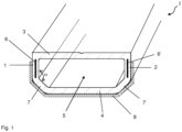
- Fig.1 shows a cross section through a spacer according to the invention for insulating glazing.
- the spacer comprises a polymer base body I, which consists for example of polypropylene (PP).
- the polymer has a glass fiber content of 0 wt.% or a relatively low glass fiber content of for example 10 wt.%.
- the base body I comprises two side walls 1, 2 which are parallel to one another and are intended to be brought into contact with the panes of the insulating glass. Between one end of each side wall 1, 2 there is an inner wall 3 which is intended to face the space between the panes of the insulating glass.
- a connecting section 7, 7' is connected to the other ends of the side walls 1, 2.
- the side walls 1, 2 are connected to an outer wall 4 via the connecting sections 7, 7', which is designed parallel to the inner wall 3.
- the angle ⁇ between the connecting sections 7 (or 7') and the side wall 3 (or 4) is approximately 45°. This means that the angle between the outer wall 4 and the connecting sections 7, 7' is also approximately 45°.
- the base body I surrounds a hollow chamber 5.
- the material thickness of the side walls 1, 2, the inner wall 3, the outer wall 4 and the connecting sections 7, 7' is approximately the same and is, for example, 1 mm.
- the base body has, for example, a height of 6.5 mm and a width of 15 mm.
- a reinforcement strip 6 is embedded in each side wall 1, 2.
- the reinforcement strips 6, 6' are made of steel, which is not stainless steel, and have a thickness (material thickness) of, for example, 0.3 mm and a width of, for example, 3 mm.
- the length of the reinforcement strips 6, 6' corresponds to the length of the base body I.
- the reinforcing strips give the base body I sufficient flexibility and stability to be bent without prior heating and to permanently maintain the desired shape.
- the spacer has a very low thermal conductivity because the metallic reinforcing strips 6, 6' are only embedded in the side walls 1, 2, via which only a very small part of the heat exchange between the interior of the pane and the external environment takes place.
- the reinforcing strips 6, 6' do not act as a thermal bridge.
- An insulating film 8 is arranged on the outer surface of the outer wall 4 and the connecting sections 7, 7' as well as a section of the outer surface of each of the side walls 1, 2.
- the insulating film 8 reduces diffusion through the spacer. This can prevent moisture from entering the interior of an insulating glazing. or the loss of the inert gas filling of the pane interior can be reduced.
- the insulation film 8 also improves the thermal properties of the spacer, thus reducing the thermal conductivity.
- the insulation film 8 comprises the following layer sequence: a polymer carrier film (consisting of LLDPE (linear low density polyethylene), thickness: 24 ⁇ m) / a metallic layer (consisting of aluminum, thickness: 50 nm) / a polymer layer (PET, 12 ⁇ m) / a metallic layer (Al, 50 nm) / a polymer layer (PET, 12 ⁇ m).
- the layer stack on the carrier film therefore contains two polymer layers and two metallic layers, wherein the polymer layers and the metallic layers are arranged alternately.
- the layer stack can also comprise further metallic layers and/or polymer layers, wherein metallic and polymer layers are preferably also arranged alternately, so that a polymer layer is arranged between each two adjacent metallic layers and a polymer layer is arranged above the uppermost metallic layer.
- the spacer according to the invention Due to the composite of polymer base body I, the reinforcing strips 6, 6' and the insulation film 8, the spacer according to the invention has advantageous properties with regard to rigidity, tightness and thermal conductivity. It is therefore particularly suitable for use in insulating glass, in particular in the window or facade area of buildings.
- Fig.2 shows a cross section through an insulating glass according to the invention in the area of the spacer.
- the insulating glass consists of two glass panes 10, 11 made of soda-lime glass with a thickness of, for example, 3 mm, which are connected to one another via a spacer according to the invention arranged in the edge area.
- the spacer is the spacer according to Fig.1 with the reinforcement strips 6,6' and the insulation foil 8.
- the side walls 1, 2 of the spacer are each connected to the glass panes 10, 11 via a sealing layer 13.
- the sealing layer 13 consists, for example, of butyl.
- An external sealing compound 9 is arranged all around the edge of the insulating glass between the glass panes 10, 11 and the spacer.
- the sealing compound 9 is, for example, a silicone rubber.
- the hollow chamber 5 of the base body I is filled with a desiccant 12.
- the desiccant 12 is, for example, a molecular sieve.
- the desiccant 12 absorbs any residual moisture present between the glass panes and the spacer and thus prevents the panes 10, 11 from fogging up in the space between the panes.
- the effect of the desiccant 12 is promoted by holes (not shown) in the inner wall 3 of the base body I.
- Fig.3 shows a flow chart of an embodiment of the method according to the invention for producing a spacer for an insulating glass.
- a spacer according to the invention was produced according to Figure 1 manufactured with the reinforcing strips 6, 6' according to the invention and the insulation film 8.
- the spacer was manufactured as a straight profile and then bent into the required shape for use in insulating glazing. It was then assessed whether the spacer had been damaged by the bending process, which prevented its use, and whether it permanently retained the desired shape. If the spacer had not been damaged and retained its shape, it was classified as "bendable”.
- the thermal conductivity of the spacer ( ⁇ value) was also measured. This was the equivalent thermal conductivity, i.e. a measurement for the entire spacer, which does not take into account the location dependence of the thermal conductivity on the spacer. The results are summarized in Table 1.
- Comparative example 1 differed from the example according to the invention in the design of the spacer. Otherwise, comparative example 1 was carried out in the same way as the example.
- the spacer in comparative example 1 had no reinforcing strips 6, 6' embedded in the side walls.
- the glass fiber content of the polymer base body I was 35% by weight. Apart from that, the spacer corresponded to that of Figure 1 The results are summarized in Table 1.
- Comparative example 2 differed from the example according to the invention in the design of the spacer. Otherwise, comparative example 2 was carried out in the same way as the example.
- the spacer in comparative example 2 had no reinforcing strips 6, 6' embedded in the side walls. Instead, a stainless steel foil with a thickness of 0.1 mm was applied to the outer surface of the side walls, the connecting sections and the outer wall in order to provide the spacer with flexibility in accordance with the prior art.
- the glass fiber content of the polymer base body I was 35% by weight. The results are summarized in Table 1. Table 1 bendable? Thermal conductivity Example Yes 0.18 W/(m*K) Comparison example 1 no 0.16 W/(m*K) Comparison example 2 Yes 0.30 W/(m*K)
- the spacer according to the invention in the example was bendable due to the reinforcement strips 6,6'.
- the thermal conductivity was only increased insignificantly by the reinforcement strips 6,6'.
- the spacer according to the invention in the example had a significantly lower thermal conductivity. The reason for this is the reinforcement strips 6,6' according to the invention, which, in contrast to the stainless steel foil according to the prior art, do not serve as a thermal bridge.
- the spacer according to the invention therefore combines sufficient flexibility with very low thermal conductivity. This result was unexpected and surprising for the person skilled in the art.
Landscapes
- Engineering & Computer Science (AREA)
- Structural Engineering (AREA)
- Civil Engineering (AREA)
- Architecture (AREA)
- Joining Of Glass To Other Materials (AREA)
- Securing Of Glass Panes Or The Like (AREA)
- Laminated Bodies (AREA)
Description
- Die Erfindung betrifft einen Abstandshalter für Isolierverglasungen, ein Verfahren zu dessen Herstellung, dessen Verwendung und eine Isolierverglasung.
- Im Fenster- und Fassadenbereich von Gebäuden werden heutzutage fast ausschließlich Isolierverglasungen eingesetzt. Isolierverglasungen bestehen zumeist aus zwei Glasscheiben, welche durch einen Abstandshalter (Spacer) in einem definierten Abstand zueinander angeordnet sind. Der Abstandshalter ist umlaufend im Randbereich der Verglasung angeordnet. Zwischen den Scheiben ist somit ein Zwischenraum ausgebildet, welcher in der Regel mit einem Inertgas gefüllt ist. Der Wärmefluss zwischen dem von der Verglasung begrenzten Innenraum und der äußeren Umgebung kann durch die Isolierverglasung im Vergleich zu einer einfachen Verglasung erheblich reduziert werden.
- Der Abstandhalter hat einen nicht zu vernachlässigenden Einfluss auf die thermischen Eigenschaften der Scheibe. Herkömmliche Abstandshalter bestehen aus einem Leichtmetall, üblicherweise Aluminium. Diese lassen sich leicht verarbeiten. Der Abstandshalter wird typischerweise als gerades Endlos-Profil hergestellt, welches auf die benötigte Größe zurechtgeschnitten und dann durch Biegen in die rechteckige Form gebracht wird, welche für den Einsatz in der Isolierverglasung notwendig ist. Aufgrund der guten Wärmeleitfähigkeit des Aluminiums wird die isolierende Wirkung der Verglasung im Randbereich allerdings deutlich herabgesetzt (cold edge-Effekt).
- Um die thermischen Eigenschaften zu verbessern, sind sogenannte warm edge-Lösungen für Abstandshalter bekannt. Diese Abstandshalter bestehen insbesondere aus Kunststoff und weisen folglich eine deutlich verringerte Wärmeleitfähigkeit auf. Kunststoff-Abstandshalter sind beispielsweise aus
DE 27 52 542 C2 oderDE 19 625 845 A1 bekannt. Was die Verarbeitung anbelangt weisen die Kunststoff-Abstandhalter aber Nachteile auf. Sie lassen sich beispielsweise durch Extrusion zwar als Endlos-Profil herstellen, jedoch erfordert das anschließende Biegen eine lokale Erwärmung des Materials, was mit herkömmlichen Maschinen nicht einfach zu realisieren ist. Solche Profile machen für den Hersteller von Isolierverglasungen also erhebliche Investitionen erforderlich. - In der
DE 10 2010 006 127 A1 ist vorgeschlagen, den Kunststoff-Abstandshalter mit einer metallischen Folie zu versehen, um die Biegbarkeit zu verbessern. Die metallische Folie ist insbesondere an den zu den Glasscheiben hingewandten Flächen und der dazwischen liegenden, vom Scheibenzwischenraum abgewandten Fläche des Abstandshalters angeordnet. Die Verbesserung der Biegeeigenschaften geht bei dieser Lösung allerdings mit einer Verschlechterung der thermischen Eigenschaften einher, weil die metallische Folie als Wärmebrücke wirkt. Die thermischen Vorteile des Kunststoff-Abstandshalter werden daher zu einem gewissen Maße wieder aufgewogen. - Aus der
DE 198 07 454 A1 ist ein Kunststoff-Abstandshalter nach dem Oberbegriff des Anspruchs 1 bekannt, in dessen Seitenwände Lochblechstreifen eingebettet sind. Die Lochblechstreifen dienen der Versteifung des Abstandshalters. Die Auswirkungen der Lochblechstreifen an die Biegbarkeit sowie damit einhergehende Anforderungen an das Material des Abstandshalters werden nicht diskutiert. - Es besteht also Bedarf an Abstandshaltern für Isolierverglasungen, welche eine minimale Wärmeleitfähigkeit gewährleisten und dennoch einfach zu verarbeiten, insbesondere biegbar sind. Der vorliegenden Erfindung liegt die Aufgabe zugrunde, einen solchen Abstandshalter bereitzustellen.
- Die Aufgabe der Erfindung wird erfindungsgemäß durch einen Abstandshalter für eine Isolierverglasung gemäß dem unabhängigen Anspruch 1 gelöst. Bevorzugte Ausführungen gehen aus den Unteransprüchen hervor.
- Der erfindungsgemäße Abstandshalter für eine Isolierverglasung aus mindestens zwei Glasscheiben umfasst mindestens einem polymeren Grundkörper. Der polymere Grundkörper umfasst mindestens zwei zueinander parallele Seitenwände, die dafür vorgesehen sind, den Glasscheiben zugewandt zu werden und mit den Glasscheiben in Kontakt gebracht zu werden, und die miteinander verbunden sind durch eine Innenwand und eine Außenwand. Die Seitenwände, die Innenwand und die Außenwand umgeben eine Hohlkammer. Eine solche Hohlkammer ist für Abstandshalter üblich und ist insbesondere zur Aufnahme eines Trockenmittels vorgesehen.
- In jede Seitenwand des polymeren Grundkörpers ist ein Verstärkungsstreifen eingelagert. Der Verstärkungsstreifen enthält bevorzugt zumindest ein Metall oder eine metallische Legierung. Unter "eingelagert" ist im Sinne der Erfindung zu verstehen, dass der Verstärkungsstreifen rundherum vom Material des polymeren Grundkörpers beziehungsweise der Seitenwände des polymeren Grundkörpers umgeben ist.
- Die Verstärkungsstreifen verleihen dem Abstandshalter die notwendige Biegbarkeit, um auch mit herkömmlichen industriellen Anlagen verarbeitet zu werden. Der Abstandshalter kann in seine endgültige Form gebogen werden, ohne vorher erwärmt werden zu müssen. Durch die Verstärkungsstreifen bleibt die Form dauerhaft stabil. Zudem erhöht der Verstärkungsstreifen die Stabilität des Abstandshalters. Die Verstärkungsstreifen wirken aber nicht als Wärmebrücke, so dass die Eigenschaften des Abstandshalters hinsichtlich der Wärmeleitung nicht wesentlich negativ beeinflusst werden. Dies hat insbesondere zwei Gründe: (a) die Verstärkungsstreifen sind in den polymeren Grundkörper eingelagert, haben also keinen Kontakt zur Umgebung; (b) die Verstärkungsstreifen in den Seitenwänden angeordnet und nicht etwa in der Außenwand oder der Innenwand, über welche der Wärmeaustausch zwischen Scheibenzwischenraum und äußerer Umgebung erfolgt. Die gleichzeitige Realisierung von Biegbarkeit und optimalen thermischen Eigenschaften ist der entscheidende Vorteil der vorliegenden Erfindung.
- Die Erfinder haben außerdem erkannt, dass die Biegbarkeit vom Glasfaseranteil des polymeren Grundkörpers abhängt. Der Glasfaseranteil liegt bei üblichen polymeren Abstandshaltern aus glasfaser-verstärktem Kunststoff bei etwa 35 Gew.-%. Durch diesen Glasfaseranteil wird eine ausreichende Stabilität des Abstandshalters erreicht. Allerdings ist der Abstandshalter mit einem so hohen Glasfaseranteil zu steif, um ohne Beschädigung gebogen werden zu können. Die Erfinder haben erkannt, dass ein Glasfaseranteil von höchstens 20 Gew.-% eine gute Biegbarkeit ermöglicht. Die mit dem verringerten Glasfaseranteil einhergehende geringere Steifigkeit und Stabilität, insbesondere auch gegenüber Rückstellkräften nach dem Biegen, wird durch die erfindungsgemäßen Verstärkungsprofile kompensiert.
- Die erfindungsgemäßen Verstärkungsstreifen in Verbindung mit dem erfindungsgemäß geringen Glasfaseranteil des polymeren Grundkörpers ermöglichen also eine gute Biegbarkeit bei gleichzeitig hoher Stabilität und Steifigkeit in Einbaulage.
- Die anderen Abschnitte des Grundkörpers außer den Seitenwänden, insbesondere die Innenwand und die Außenwand, weisen bevorzugt keine metallischen Einlagerungen auf.
- Die Wärmeleitfähigkeit (λ-Wert) des Abstandshalters beträgt bevorzugt kleiner als 0,25 W/(m*K), besonders bevorzugt kleiner als 0,2 W/(m*K). Damit ist die für den gesamten Abstandshalter gemessene Wärmeleitfähigkeit gemeint (Äquivalent-Wärmeleitfähigkeit) ohne Berücksichtigung lokaler Schwankungen der Wärmeleitfähigkeit in Abhängigkeit von der genauen Position auf dem Abstandshalter. Solch geringe Wärmeleitfähigkeiten sind überraschenderweise durch einen polymeren Grundkörper mit dem erfindungsgemäßen Verstärkungsprofil zu erreichen.
- Die Seitenwände des polymeren Grundkörpers sind dafür vorgesehen, in der gefertigten Isolierverglasung den Glasscheiben zugewandt zu sein. Der Kontakt des Abstandshalters mit den Glasscheiben erfolgt über die Seitenwände. Es muss dabei kein direkter Kontakt zwischen Abstandhalter und Scheibe vorliegen. Stattdessen kann der Kontakt mittelbar, beispielsweise über eine Dichtmasse erfolgen.
- Die Innenwand ist dafür vorgesehen, in der gefertigten Isolierverglasung dem Zwischenraum zwischen den Glasscheiben zugewandt zu ein. Die Innenwand ist in einer vorteilhaften Ausgestaltung mit Löchern versehen, um die Wirkung eines Trockenmittels in der Hohlkammer auf den Zwischenraum zu gewährleisten.
- Die Außenwand liegt der Innenwand gegenüber und ist dafür vorgesehen, der äußeren Umgebung der Isolierverglasung zugewandt zu sein. Die Außenwand weist aus dem Zwischenraum zwischen den Glasscheiben, in welchem der Abstandshalter angeordnet ist, heraus.
- Die Seitenwände, die Außenwand und die Innenwand und gegebenenfalls die Verbindungsabschnitte weisen jeweils bevorzugt eine Dicke (Materialstärke) von 0,5 mm bis 2 mm, besonders bevorzugt von 0,8 mm bis 1,5 mm auf. Die Dicke des polymeren Grundkörpers ist bevorzugt konstant, das heißt alle Wände und Abschnitte weisen die gleiche Dicke auf. Ein solcher Abstandshalter ist einfach zu verarbeiten und vorteilhaft stabil.
- Die Innenwand, die Außenwand und die Seitenwände sind in einer bevorzugten Ausgestaltung jeweils plan ausgebildet. Die Innenwand, die Außenwand und die Seitenwände sind in diesem Sinne also plane Abschnitte des polymeren Grundkörpers. Jede Wand ist an ihren Enden mit den jeweiligen Enden der beiden benachbarten Wände verbunden. Die Seitenwände können direkt mit der Innenwand und der Außenwand verbunden sein.
- In einer bevorzugten Ausgestaltung ist die Innenwand direkt mit den Seitenwänden verbunden, während die Außenwand indirekt, nämlich über Verbindungsabschnitte mit den Seitenwänden verbunden ist. Die Verbindungsabschnitte sind bevorzugt ebenfalls plan ausgebildet. Die Innenwand ist bevorzugt in einem Winkel von etwa 90° zu jeder Seitenwand angeordnet. Die Seitenwände sind zueinander parallel und die Innenwand ist parallel zur Außenwand. Die Verbindungsabschnitte sind bevorzugt in einem Winkel zu jeder Seitenwand von 120 ° bis 150°, idealerweise 135° angeordnet. Diese Form für den Abstandhalter hat sich besonders bewährt.
- Die Breite des polymeren Grundkörpers beträgt bevorzugt von 5 mm bis 35 mm, besonders bevorzugt von 5 mm bis 33 mm, beispielsweise von 10 mm bis 20 mm. Die Breite ist im Sinne der Erfindung die sich zwischen den Seitenwänden erstreckende Dimension. Die Breite ist der Abstand zwischen den voneinander abgewandten Flächen der beiden Seitenwände. Die Breite des Grundkörpers legt in die Isolierverglasung den Abstand der beiden Glasscheiben fest.
- Die Höhe des polymeren Grundkörpers beträgt bevorzugt von 3 mm bis 20 mm, besonders bevorzugt von 5 mm bis 10 mm und ganz besonders bevorzugt von 5 mm bis 8 mm. In diesem Bereich für die Höhe besitzt der Abstandshalter eine vorteilhafte Stabilität, ist aber andererseits in der Isolierverglasung vorteilhaft unauffällig. Außerdem weist die Hohlkammer des Abstandshalters eine vorteilhafte Größe zur Aufnahme einer geeigneten Menge an Trockenmittel auf. Die Höhe ist der Abstand zwischen den voneinander abgewandten Flächen der Außenwand und der Innenwand.
- Der polymere Grundkörper enthält bevorzugt zumindest Polyethylen (PE), Polycarbonate (PC), Polypropylen (PP), Polystyrol, Polybutadien, Polynitrile, Polyester, Polyurethane, Polymethylmetacrylate, Polyacrylate, Polyamide, Polyethylenterephthalat (PET), Polybutylenterephthalat (PBT), Acrylnitril-Butadien-Styrol (ABS), Acrylester-Styrol-Acrylnitril (ASA), Acrylnitril-Butadien-Styrol-Polycarbonat (ABS/PC), Styrol-Acrylnitril (SAN), Polyethylenterephthalat-Polycarbonat (PET/PC), Polybutylenterephthalat- Polycarbonat (PBT/PC) oder Copolymere oder Derivate oder Gemische davon. Der polymere Grundkörper enthält besonders bevorzugt Polypropylen (PP), Acrylnitril-Butadien-Styrol (ABS), Acrylester-Styrol-Acrylnitril (ASA), Acrylnitril-Butadien-Styrol-Polycarbonat (ABS/PC), Styrol-Acrylnitril (SAN), Polyethylenterephthalat-Polycarbonat (PET/PC), Polybutylenterephthalat-Polycarbonat (PBT/PC) oder Copolymere oder Derivate oder Gemische davon. Diese Materialen sind besonders vorteilhaft im Hinblick auf eine geringe Wärmeleitung und gute Verarbeitung.
- Der polymere Grundkörper weist einen Glasfaser-Anteil von 0 Gew.-% bis 20 Gew.-% auf, besonders bevorzugt von 0 Gew.-% bis 15 Gew.-%. Im Vergleich zu polymeren Abstandshaltern nach dem Stand der Technik, welche in der Regel einen Glasfaser-Anteil von etwa 35 Gew.-% aufweisen, ist der Glasfaser-Anteil gering. Dadurch wird zwar die Steifigkeit und Stabilität des Abstandshalters verringert, aber die Biegbarkeit vorteilhaft verbessert. Die reduzierte Stabilität, insbesondere auch gegenüber Rückstellkräften nach dem Biegen, wird durch die erfindungsgemäßen Verstärkungsprofile kompensiert.
- In einer vorteilhaften Ausgestaltung beträgt der Glasfaser-Anteil 0 Gew.-%, der polymere Grundkörper enthält also keinen glasfaserverstärkten Kunststoff. In einer weiteren vorteilhaften Ausgestaltung enthält der polymere Grundkörper glasfaserverstärkten Kunststoff, wobei der Glasfaser-Anteil kleiner 20 Gew.-% beträgt, bevorzugt kleiner 15 Gew.-%. Durch einen Glasfaseranteil kann insbesondere der Wärmeausdehnungskoeffizient des Grundkörpers variiert und angepasst werden.
- Der erfindungsgemäße Verstärkungsstreifen enthält in einer bevorzugten Ausgestaltung zumindest Stahl. Stahl ist leicht verfügbar, gut zu verarbeiten und verleiht dem Abstandshalter eine besonders vorteilhafte Biegbarkeit und verbessert zudem die Stabilität und Steifigkeit. Der Stahl ist besonders bevorzugt kein Edelstahl, was im Hinblick auf die Kosten für den Abstandshalter besonders vorteilhaft ist. Eine Korrosion des Stahls wird durch die Einlagerung in den polymeren Grundkörper verhindert.
- Der Verstärkungsstreifen weist eine Dicke von 0,2 mm bis 0,4 mm, insbesondere von 0,25 mm bis 0,35 mm auf. In einer besonders bevorzugten Ausgestaltung beträgt die Dicke des Verstärkungsstreifens etwa 0,3 mm. Damit werden besonders gute Ergebnisse hinsichtlich die Biegbarkeit, Steifigkeit und Stabilität des Abstandshalters erreicht.
- Der Verstärkungsstreifen weist eine Breite von 1 mm bis 5 mm auf. Damit wird eine gute Biegbarkeit und Versteifung erreicht. Die Breite des verstärkungssteifens ist im Einzelfall natürlich auch von der Breite der Seitenwand abhängig.
- Die Länge des Verstärkungsstreifens entspricht bevorzugt der Länge des polymeren Grundkörpers.
- Der Verstärkungsstreifen kann in einer Ausbildung der Erfindung perforiert sein. Durch eine geeignete Perforation kann die Biegbarkeit vorteilhaft beeinflusst werden.
- In einer vorteilhaften Ausgestaltung ist der Verstärkungsstreifen über einen Haftvermittler mit dem polymeren Grundkörper verbunden. Jede Kontaktfläche zwischen Verstärkungsstreifen und Grundkörper ist bevorzugt mit dem Haftvermittler versehen. Das ist besonders vorteilhaft für die Haftung zwischen polymerem Grundkörper und Verstärkungsstreifen und damit für die Stabilität des Abstandshalters. Der Abstandshalter ist mit einer Isolationsfolie versehen. Die Isolationsfolie verringert die Wärmeleitfähigkeit des Abstandshalters weiter. Die Isolationsfolie verhindert außerdem die Diffusion durch den Abstandshalter. So wird insbesondere das Eindringen von Feuchtigkeit in den Scheibenzwischenraum und der Verlust eines Inertgases aus dem Scheibenzwischenraum verhindert. Die Isolationsfolie weist bevorzugt eine Gaspermeation kleiner als 0,001 g/(m2 h) auf.
- Die Isolationsfolie ist zumindest auf der Außenfläche der Außenwand angeordnet. Mit Außenfläche wird im Sinne der Erfindung die von der Hohlkammer abgewandte Oberfläche einer Wand bezeichnet. Bevorzugt ist die Isolationsfolie zumindest auf der Außenfläche des gesamten die Außenwand enthaltenden Abschnitts des Grundkörpers zwischen den Seitenwänden angeordnet. Ist die Außenwand beispielsweise über jeweils einen Verbindungsabschnitt mit den Seitenwänden verbunden, so ist die Isolationsfolie auf den Außenflächen der Außenwand und der beiden Verbindungsabschnitte angeordnet. In einer besonders vorteilhaften Ausgestaltung die Isolationsfolie auf der Außenfläche des gesamten die Außenwand enthaltenden Abschnitts des Grundkörpers zwischen den Seitenwänden angeordnet und zusätzlich mindestens auf der Außenfläche von zumindest einem Abschnitt jeder Seitenwand. Die Isolationsfolie erstreckt sich also von der ersten Seitenwand über die Außenwand (und gegebenenfalls Verbindungsabschnitte) zur gegenüberliegenden Seitenwand. Damit werden besonders gute Ergebnisse hinsichtlich der Stabilität des Verbunds aus polymerem Grundkörper und Isolationsfile sowie hinsichtlich der thermischen Eigenschaften des Abstandshalters erreicht.
- Die Isolationsfolie enthält mindestens eine polymere Folie. Die polymere Folie dient als Trägerfolie und weist bevorzugt eine Dicke von 10 µm bis 100 µm auf, besonders bevorzugt von 15 µm bis 60 µm, was vorteilhaft für die Stabilität der Isolationsfolie ist.
- Die Isolationsfolie enthält außerdem zumindest eine mindestens eine metallische oder keramische Schicht, die auf der Trägerfolie aufgebracht ist. Die Dicke der metallischen beziehungsweise keramischen Schicht beträgt bevorzugt von 10 nm bis 1500 nm, besonders bevorzugt von 10 nm bis 400 nm, ganz besonders bevorzugt von 30 nm bis 200 nm. Damit werden besonders gute Ergebnisse hinsichtlich der Isolationswirkung erreicht.
- Die Isolationsfolie enthält bevorzugt mindestens eine weitere polymere Schicht, deren Dicke bevorzugt von 5 µm bis 100 µm, besonders bevorzugt von 15 µm bis 60 µm beträgt.
- In einer besonders bevorzugten Ausführungsform bestehen die polymere Trägerolie und die polymere Schicht aus dem gleichen Material. Dies ist besonders vorteilhaft, da eine geringere Vielfalt der verwendeten Materialien den Produktionsablauf vereinfacht. Dabei weisen die polymere Folie und die polymere Schicht oder die polymeren Schichten bevorzugt die gleiche Materialstärke auf, so dass das gleiche Ausgangsmaterial für alle polymeren Bestandteile der Isolationsfolie verwendet werden kann.
- Die polymere Folie und/oder die polymere Schicht enthalten bevorzugt zumindest Polyethylenterephthalat, Ethylenvinylalkohol, Polyvinylidenchlorid, Polyamide, Polyethylen, Polypropylen, Silikone, Acrylonitrile, Polymethylacrylate oder Copolymere oder Gemische davon.
- Eine metallische Schicht enthält bevorzugt Eisen, Aluminium, Silber, Kupfer, Gold, Chrom oder Legierungen oder Gemische davon.
- Eine keramische Schicht enthält bevorzugt Siliziumoxid und/oder Siliziumnitrid.
- Die Isolationsfolie enthält bevorzugt mindestens zwei metallische oder keramische Schichten, wobei zwischen zwei benachbarten metallischen oder keramischen Schichten jeweils mindestens eine polymere Schicht angeordnet ist. Das ist besonders vorteilhaft für die isolierende Wirkung der polymeren Folie, insbesondere weil eventuelle Defekte innerhalb einer Schicht durch eine der anderen Schichten ausgeglichen werden können. Zudem weisen mehrere dünne Schichten im Vergleich zu einer einzelnen dicken Schicht bessere Haftungseigenschaften auf. Bevorzugt ist die oberste Schicht der Isolationsfolie eine polymere Schicht, was dem Schutz der metallischen beziehungsweise keramischen Schichten dient. Die oberste Schicht ist dabei diejenige Schicht, die den größten Abstand zur polymeren Trägerfolie aufweist. Die Isolationsfolie weist in einer besonders vorteilhaften Ausgestaltung von zwei bis vier metallische oder keramische Schichten auf. Die metallischen oder keramischen Schichten sind bevorzugt jeweils alternierend mit mindestens einer polymeren Schicht angeordnet.
- Die Erfindung umfasst weiter eine Isolierverglasung, mindestens umfassend zwei parallel zueinander angeordnete Glasscheiben und einen im Randbereich zwischen den Glasscheiben angeordneten erfindungsgemäßen Abstandshalter. Der Abstandshalter ist bevorzugt umlaufend rahmenförmig ausgebildet. Jede Seitenwand ist einer der Glasscheiben zugewandt und mit der jeweiligen Glasscheibe in Kontakt gebracht. Die Seitenwände des Abstandshalters sind bevorzugt über eine Dichtungsschicht mit den Glasscheiben verbunden. Als Dichtungsschicht eignet sich beispielsweise Butyl. Zumindest auf der Außenwand des Abstandshalters, bevorzugt im Randraum zwischen den Scheiben und dem Abstandshalter ist bevorzugt eine äußere Dichtmasse angeordnet. Die äußere, bevorzugt plastische Dichtmasse enthält beispielsweise Polymere oder silanmodifizierte Polymere, besonders bevorzugt organische Polysulfide, Silikone, RTV (raumtemperturvernetzenden)-Silikonkautschuk, HTV-(hochtemperturvernetzenden) Silikonkautschuk, peroxidischvernetzten-Silikonkautschuk und/oder additionsvernetzten-Silikonkautschuk, Polyurethane, Buthylkautschuk und/oder Polyacrylate.
- Der Scheibenzwischenraum ist bevorzugt evakuiert oder mit einem Inertgas gefüllt, beispielsweise Argon oder Krypton.
- Die Hohlkammer des Abstandshalters ist bevorzugt vollständig oder teilweise mit einem Trockenmittel gefüllt. Restfeuchtigkeit im Scheibenzwischenraum wird durch das Trockenmittel aufgenommen, so dass die Scheiben nicht beschlagen können. Als Trockenmittel eignen sich insbesondere Kieselgele, Molekularsiebe, CaCl2, Na2SO4, Aktivkohle, Silikate, Bentonite, und/oder Zeolithe.
- Die Isolierverglasung weist bevorzugt einen Psi-Wert von kleiner 0,05 W/(m*K), bevorzugt kleiner 0,035 W/(m*K) auf. Der Psi-Wert wird als Wärmeleitfähigkeit am Isolierglas mit Rahmensystem gemessen.
- Die Glasscheiben bestehen bevorzugt aus Kalk-Natron-Glas. Die Dicke der Scheiben kann prinzipiell beliebig variiert werden, gebräuchlich ist insbesondere eine Dicke von 1 mm bis 25 mm, bevorzugt von 3 mm bis 19 mm auf. Die Transparenz der Scheiben beträgt bevorzugt größer als 85%.
- Die Isolierverglasung kann natürlich auch mehr als zwei Glasscheiben umfassen, wobei zwischen jeweils zwei benachbarten Glasscheiben bevorzugt ein erfindungsgemäßer Abstandshalter angeordnet ist.
- Die Aufgabe der Erfindung wird weiter erfindungsgemäß durch ein Verfahren zur Herstellung eines erfindungsgemäßen Abstandshalters für eine Isolierverglasung gelöst, wobei
- a) zwei Verstärkungsstreifen parallel zueinander angeordnet werden,
- b) die Verstärkungsstreifen mit einem polymeren Material umspritzt werden, wobei der polymere Grundkörper entsteht,
- c) eine Isolationsfolie zumindest auf der Außenwand des Grundkörpers angebracht wird,
- d) der polymere Grundkörper mit den Verstärkungsstreifen zurechtgeschnitten wird und
- e) der polymere Grundkörper mit den Verstärkungsstreifen in eine umlaufende Rahmenform gebogen wird.
- Der polymere Grundkörper mit den Verstärkungsstreifen wird als Endlos-Profil durch Extrusion hergestellt. Es wird aus diesem Endlos-Profil ein Profilabschnitt mit der für den Einsatz im Isolierglas erforderlichen Länge zurechtgeschnitten. Der Profilabschnitt weist ein erstes und ein zweites Ende auf. Der Profilabschnitt wird dann auf die umlaufende, üblicherweise rechteckige Rahmenform gebogen. Dabei werden die Enden bevorzugt miteinander verbunden, beispielsweise durch eine Steckverbindung, um die Stabilität der Rahmenform zu verbessern.
- Die Hohlkammer des Abstandshalters wird bevorzugt mit einem Trockenmittel befüllt. Das Trockenmittel kann alternativ auch zusammen mit dem Grundkörper extrudiert werden.
- Das Biegen des Profilabschnitts erfolgt bevorzugt ohne vorheriges Erwärmen, insbesondere bei Umgebungstemperatur. Es ist ein besonderer Vorteil des Abstandshalters mit den erfindungsgemäßen Verstärkungsstreifen, dass eine solche Erwärmung nicht erforderlich ist. So kann der Abstandshalter auf herkömmlichen industriellen Fertigungsanlagen verarbeitet werden.
- In einer bevorzugten Ausführung wird der polymere Grundkörper mit einer erfindungsgemäßen Isolationsfolie versehen. Bevorzugt erfolgt dies vor dem Biegen des Abstandshalters. Die Isolationsfolie kann beispielsweise durch Kleben auf dem Grundkörper aufgebracht werden oder auch zusammen mit dem Grundkörper extrudiert werden.
- Das erfindungsgemäße Isolierglas wird hergestellt, indem der rahmenförmige Abstandshalter im Randbereich zwischen zwei parallelen Glasscheiben angeordnet wird. Die Glasscheiben werden mit dem Abstandshalter verbunden, bevorzugt durch Pressen und über jeweils eine Dichtungsschicht. Anschließend wird eine äußere Dichtmasse zumindest auf der Außenwand angeordnet. Bevorzugt wird der Randraum zwischen den Scheiben und dem Abstandshalter umlaufend mit der äußeren Dichtmasse gefüllt.
- Der durch den rahmenförmigen Abstandshalter begrenzte Zwischenraum zwischen den Glasscheiben wird bevorzugt mit Unterdruck beaufschlagt und/oder mit einem Inertgas befüllt.
- Die Erfindung umfasst weiter die Verwendung des erfindungsgemäßen Abstandshalters in Mehrfachverglasungen, bevorzugt in Isolierverglasungen. Die Isolierverglasungen werden bevorzugt verwendet als Fensterverglasungen oder Fassadenverglasungen von Gebäuden.
- Im Folgenden wird die Erfindung anhand einer Zeichnung und Ausführungsbeispielen näher erläutert. Die Zeichnung ist eine schematische Darstellung und nicht maßstabsgetreu. Die Zeichnung schränkt die Erfindung in keiner Weise ein.
- Es zeigen:
-
Fig. 1 einen perspektivischer Querschnitt durch eine Ausgestaltung des erfindungsgemäßen Abstandshalters, -
Fig. 2 einen Querschnitt durch eine Ausgestaltung der erfindungsgemäßen Isolierverglasung mit dem erfindungsgemäßen Abstandshalter und -
Fig. 3 ein Flussdiagramm einer Ausführungsform des erfindungsgemäßen Verfahrens. -
Fig. 1 zeigt einen Querschnitt durch einen erfindungsgemäßen Abstandshalter für eine Isolierverglasung. Der Abstandhalter umfasst einen polymeren Grundkörper I, welcher beispielsweise aus Polypropylen (PP) besteht. Das Polymer weist dabei einen Glasfaseranteil von 0 Gew.-% oder einen relativ geringen Glasfaseranteil von beispielsweise 10 Gew.-% auf. - Der Grundkörper I umfasst zwei zueinander parallel Seitenwände 1, 2, welche dafür vorgesehen sind, mit den Scheiben des Isolierglases in Kontakt gebracht zu werden. Zwischen jeweils einem Ende jeder Seitenwand 1,2 verläuft eine Innenwand 3, welche dafür vorgesehen ist, dem Scheibenzwischenraum des Isolierglases zugewandt zu werden. An den anderen Enden der Seitenwände 1, 2 schließt sich jeweils ein Verbindungsabschnitt 7, 7' an. Über die Verbindungsabschnitte 7, 7' sind die Seitenwände 1, 2 mit einer Außenwand 4 verbunden, welche parallel zur Innenwand 3 ausgebildet ist. Der Winkel α zwischen den Verbindungsabschnitten 7 (beziehungsweise 7') und der Seitenwand 3 (beziehungsweise 4) beträgt etwa 45°. Daraus ergibt sich, dass auch der Winkel zwischen der Außenwand 4 und den Verbindungsabschnitten 7, 7' etwa 45° beträgt. Der Grundkörper I umgibt eine Hohlkammer 5.
- Die Materialstärke (Dicke) der Seitenwände 1, 2, der Innenwand 3, der Außenwand 4 und der Verbindungsabschnitte 7, 7' ist etwa gleich und beträgt beispielsweise 1 mm. Der Grundkörper weist beispielsweise eine Höhe von 6,5 mm und eine Breite von 15 mm auf.
- In jede Seitenwand 1, 2 ist ein Verstärkungsstreifen 6 eingelagert. Die Verstärkungsstreifen 6, 6' bestehen aus Stahl, welcher kein Edelstahl ist, und weisen eine Dicke (Materialstärke) von beispielsweise 0,3 mm auf und eine Breite von beispielsweise 3 mm. Die Länge der Verstärkungsstreifen 6, 6' entspricht der Länge des Grundkörpers I.
- Die Verstärkungsstreifen verleihen dem Grundkörper I eine hinreichende Biegbarkeit und Stabilität, um ohne vorherige Erwärmung gebogen zu werden und die gewünschten Form dauerhaft beizubehalten. Im Gegensatz zu anderen Lösungen nach dem Stand der Technik weist der Abstandshalter dabei eine sehr geringe Wärmeleitfähigkeit auf, weil die metallischen Verstärkungsstreifen 6, 6' nur in die Seitenwände 1,2 eingelagert sind, über welche nur ein sehr geringer Teil des Wärmeaustauschs zwischen Scheibeninnenraum und äußerer Umgebung stattfindet. Die Verstärkungsstreifen 6, 6' nicht als Wärmebrücke. Das sind große Vorteile der vorliegenden Erfindung.
- Auf der Außenfläche der Außenwand 4 und der Verbindungsabschnitte 7, 7' sowie einem Abschnitt der Außenfläche jeder der Seitenwände 1, 2 ist eine Isolationsfolie 8 angeordnet. Die Isolationsfolie 8 verringert eine Diffusion durch den Abstandshalter hindurch. Dadurch kann der Feuchtigkeitseintritt in den Scheibeninnenraum einer Isolierverglasung oder der Verlust der Inertgasfüllung des Scheibeninnenraums verringert werden. Die Isolationsfolie 8 verbessert außerdem die thermischen Eigenschaften des Abstandshalters, verringert also die Wärmeleitfähigkeit.
- Die Isolationsfolie 8 umfasst die folgende Schichtenfolge: eine polymere Trägerfolie (bestehend aus LLDPE (lineares Polyethylen niedriger Dichte), Dicke: 24 µm) / eine metallische Schicht (bestehend aus Aluminium, Dicke: 50 nm) / eine polymere Schicht (PET, 12 µm) / eine metallische Schicht (Al, 50 nm) / eine polymere Schicht (PET, 12 µm). Der Schichtstapel auf der Trägerfolie enthält also zwei polymeren Schichten und zwei metallische Schichten, wobei die polymeren Schichten und die metallischen Schichten alternierend angeordnet sind. Der Schichtstapel kann auch weitere metallische Schichten und/oder polymere Schichten umfassen, wobei metallische und polymere Schichten bevorzugt ebenfalls alternierend angeordnet sind, so dass zwischen jeweils zwei benachbarten metallischen Schichten eine polymere Schicht angeordnet ist und oberhalb der obersten metallischen Schicht eine polymere Schicht angeordnet ist.
- Durch den Verbund aus polymerem Grundkörper I, den Verstärkungsstreifen 6,6' und der Isolationsfolie 8 weist der erfindungsgemäße Abstandshalter vorteilhafte Eigenschaften hinsichtlich der Steifigkeit, der Dichtigkeit und der Wärmeleitfähigkeit auf. Er eignet sich daher in besonderem Maße für die Verwendung in Isoliergläser, insbesondere im Fenster- oder Fassadebereich von Gebäuden.
-
Fig. 2 zeigt einen Querschnitt durch ein erfindungsgemäßes Isolierglas im Bereich des Abstandshalters. Das Isolierglas besteht aus zwei Glasscheiben 10, 11 aus Kalk-Natron-Glas mit einer Dicke von beispielsweise 3 mm, die über einen im Randbereich angeordneten erfindungsgemäßen Abstandshalter miteinander verbunden sind. Der Abstandshalter ist der Abstandshalter gemäßFig. 1 mit den Verstärkungsstreifen 6,6' und der Isolationsfolie 8. - Die Seitenwände 1, 2 des Abstandshalters sind über jeweils eine Dichtungsschicht 13 mit den Glasscheiben 10, 11 verbunden. Die Dichtungsschicht 13 besteht beispielsweise aus Butyl. Im Randraum des Isolierglases zwischen den Glasscheiben 10, 11 und dem Abstandshalter ist umlaufend eine äußere Dichtmasse 9 angeordnet. Die Dichtmasse 9 ist beispielsweise ein Silikonkautschuk.
- Die Hohlkammer 5 des Grundkörper I ist mit einem Trockenmittel 12 gefüllt. Das Trockenmittel 12 ist beispielsweise ein Molekularsieb. Das Trockenmittel 12 nimmt eine zwischen den Glasscheiben und dem Abstandshalter vorhandene Restfeuchtigkeit auf und verhindert so das Beschlagen der Scheiben 10, 11 im Scheibenzwischenraum. Die Wirkung des Trockenmittels 12 wird durch nicht dargestellte Löcher in der Innenwand 3 des Grundkörpers I begünstigt.
-
Fig. 3 zeigt ein Flussdiagramm eines Ausführungsbeispiels des erfindungsgemäßen Verfahrens zur Herstellung eines Abstandshalters für ein Isolierglas. - Es wurde ein erfindungsgemäßer Abstandshalter gemäß
Figur 1 hergestellt mit den erfindungsgemäßen Verstärkungsstreifen 6, 6' und der Isolationsfolie 8. Der Abstandshalter wurde als gerades Profil hergestellt und anschließend in die benötigte Form für den Einsatz in einer Isolierverglasung gebogen. Anschließend wurde bewertet, ob der Abstandshalter durch den Biegevorgang Schaden genommen hat, der seiner Verwendung entgegen steht, und ob er die gewünschte Form dauerhaft beibehält. In dem Fall, dass der Abstandshalter keinen Schaden genommen hat und seine Form beibehielt, wurde er als "biegbar" eingestuft. Außerdem wurde die Wärmeleitfähigkeit des Abstandshalters (λ-Wert) gemessen. Es handelte sich dabei um die Äquivalent-Wärmeleitfähigkeit, also eine Messung für den Gesamt-Abstandshalter, welche die Ortsabhängigkeit der Wärmeleitfähigkeit auf dem Abstandshalter unberücksichtigt lässt. Die Ergebnisse sind in Tabelle 1 zusammengefasst. - Das Vergleichsbeispiel 1 unterschied sich vom erfindungsgemäßen Beispiel durch die Ausgestaltung des Abstandshalters. Ansonsten wurde das Vergleichsbeispiel 1 genauso durchgeführt wie das Beispiel. Der Abstandshalter im Vergleichsbeispiel 1 wies keine in die Seitenwände eingelagerten Verstärkungsstreifen 6, 6' auf. Außerdem betrug der Glasfaseranteil des polymeren Grundkörpers I 35 Gew.-%. Davon abgesehen entsprach der Abstandshalter demjenigen aus
Figur 1 . Die Ergebnisse sind in Tabelle 1 zusammengefasst. - Das Vergleichsbeispiel 2 unterschied sich vom erfindungsgemäßen Beispiel durch die Ausgestaltung des Abstandshalters. Ansonsten wurde das Vergleichsbeispiel 2 genauso durchgeführt wie das Beispiel. Der Abstandshalter im Vergleichsbeispiel 2 wies keine in die Seitenwände eingelagerten Verstärkungsstreifen 6, 6' auf. Stattdessen war auf der Außenfläche der Seitenwände, der Verbindungsabschnitte und der Außenwand eine Edelstahlfolie mit einer Dicke von 0,1 mm aufgebracht, um den Abstandshalter gemäß dem Stand der Technik mit einer Biegbarkeit zu versehen. Der Glasfaseranteil des polymeren Grundkörpers I betrug 35 Gew.-%. Die Ergebnisse sind in Tabelle 1 zusammengefasst.
Tabelle 1 biegbar? Wärmeleitfähigkeit Beispiel ja 0,18 W/(m*K) Vergleichsbeispiel 1 nein 0,16 W/(m*K) Vergleichsbeispiel 2 ja 0,30 W/(m*K) - Der erfindungsgemäße Abstandshalter im Beispiel war im Gegensatz zum Abstandshalter des Vergleichsbeispiels 1 biegbar aufgrund der Verstärkungsstreifen 6,6'. Die Wärmeleitfähigkeit wurde durch die Verstärkungsstreifen 6,6' aber nur unwesentlich erhöht. Der erfindungsgemäße Abstandshalter im Beispiel wies im Gegensatz zum Abstandshalter des Vergleichsbeispiels 2 eine deutlich geringe Wärmeleitfähigkeit auf. Der Grund dafür sind die erfindungsgemäßen Verstärkungsstreifen 6,6', die im Gegensatz zu der Edelstahlfolie nach dem Stand der Technik nicht als Wärmebrücke dient.
- Der erfindungsgemäße Abstandshalter vereint also eine hinreichende Biegbarkeit mit einer sehr geringen Wärmeleitfähigkeit. Dieses Ergebnis war für den Fachmann unerwartet und überraschend.
-
- (I)
- polymerer Grundkörper
- (1)
- Seitenwand
- (2)
- Seitenwand
- (3)
- Innenwand
- (4)
- Außenwand
- (5)
- Hohlkammer
- (6,6')
- Verstärkungsstreifen
- (7,7')
- Verbindungsabschnitt
- (8)
- Isolationsfolie
- (9)
- äußere Dichtmasse
- (10)
- Glasscheibe
- (11)
- Glasscheibe
- (12)
- Trockenmittel
- (13)
- Dichtungsschicht
- α
- Winkel zwischen Seitenwand 1,2 und Verbindungsabschnitt 7,7'
Claims (14)
- Abstandshalter für eine Isolierverglasung, mindestens umfassend:- einen polymeren Grundkörper (I), mindestens umfassend zwei zueinander parallele Seitenwände (1,2), die miteinander verbunden sind durch eine Innenwand (3) und eine Außenwand (4), wobei die Seitenwände (1,2), die Innenwand (3) und die Außenwand (4) eine Hohlkammer (5) umgeben, und- zumindest auf der Außenwand (4) eine Isolationsfolie (8), welche eine polymere Trägerfolie und mindestens eine metallische oder keramische Schicht enthält,wobei in jede Seitenwand (1,2) ein Verstärkungsstreifen (6,6') eingelagert ist, welcher zumindest ein Metall oder eine metallische Legierung enthält,dadurch gekennzeichnet, dass der Grundkörper (I) einen Glasfaser-Anteil von 0 Gew.-% bis 20 Gew.-% aufweistund wobei der Verstärkungsstreifen (6,6') eine Dicke von 0,2 mm bis 0,4 mm und eine Breite von 1 mm bis 5 mm aufweist.
- Abstandshalter nach Anspruch 1, wobei der Verstärkungsstreifen (6,6') zumindest Stahl enthält, der bevorzugt kein Edelstahl ist.
- Abstandshalter nach Anspruch 1 oder 2, wobei der Verstärkungsstreifen (6,6') eine Dicke von 0,25 mm bis 0,35 mm aufweist.
- Abstandshalter nach einem der Ansprüche 1 bis 3, wobei die Dicke der polymeren Trägerfolie der Isolationsfolie (8) von 10 µm bis 100 µm und die Dicke der metallischen oder keramischen Schicht der Isolationsfolie (8) von 10 nm bis 1500 nm beträgt und wobei die Isolationsfolie (8) mindestens eine weitere polymere Schicht mit einer Dicke von 5 µm bis 100 µm enthält.
- Abstandshalter nach Anspruch 4, wobei die Isolationsfolie (8) von zwei bis vier metallische oder keramische Schichten enthält, die jeweils alternierend mit mindestens einer polymeren Schicht angeordnet sind.
- Abstandshalter nach Anspruch 4 oder 5, wobei die metallische oder keramische Schicht der Isolationsfolie (8) zumindest Eisen, Aluminium, Silber, Kupfer, Gold, Chrom, Siliziumoxid, Siliziumnitrid oder Legierungen oder Gemische davon enthält und wobei die polymere Trägerfolie der Isolationsfolie (8) zumindest Polyethylenterephthalat, Ethylenvinylalkohol, Polyvinylidenchlorid, Polyamide, Polyethylen, Polypropylen, Silikone, Acrylonitrile, Polymethylacrylate oder Copolymere oder Gemische enthält.
- Abstandshalter nach einem der Ansprüche 1 bis 6, wobei der Grundkörper (I) zumindest Polyethylen (PE), Polycarbonate (PC), Polystyrol, Polybutadien, Polynitrile, Polyester, Polyurethane, Polymethylmetacrylate, Polyacrylate, Polyamide, Polyethylenterephthalat (PET), Polybutylenterephthalat (PBT), bevorzugt Polypropylen (PP), Acrylnitril-Butadien-Styrol (ABS), Acrylester-Styrol-Acrylnitril (ASA), Acrylnitril-Butadien-Styrol-Polycarbonat (ABS/PC), Styrol-Acrylnitril (SAN), Polyethylenterephthalat-Polycarbonat (PET/PC), Polybutylenterephthalat-Polycarbonat (PBT/PC) oder Copolymere oder Derivate oder Gemische davon enthält.
- Abstandshalter nach einem der Ansprüche 1 bis 7, wobei der Grundkörper (I) einen Glasfaser-Anteil von 0 Gew.-% bis 15 Gew.-% aufweist.
- Abstandshalter nach einem der Ansprüche 1 bis 8, wobei der Verstärkungsstreifen (6,6') perforiert ist.
- Abstandshalter nach einem der Ansprüche 1 bis 9, wobei die Seitenwände (1,2), die Innenwand (3) und die Außenwand (4) jeweils plan sind und die Innenwand (3) direkt mit den Seitenwänden (1,2) verbunden ist und die Außenwand (4) über plane Verbindungsabschnitte (7,7') mit den Seitenwänden (1,2) verbunden ist, wobei der Winkel α zwischen der Seitenwand (1,2) und dem Verbindungsabschnitt (7,7') von 120° bis 150° beträgt.
- Abstandshalter nach einem der Ansprüche 1 bis 10, der eine Wärmeleitfähigkeit von kleiner als 0,25 W/(m*K), bevorzugt kleiner 0,2 W/(m*K) aufweist.
- Isolierverglasung, mindestens umfassend zwei parallel zueinander angeordnete Glasscheiben (10,11), einen im Randbereich zwischen den Glasscheiben (10,11) angeordneten Abstandshalter nach einem der Ansprüche 1 bis 11, wobei jede Seitenwand (1,2) einer der Glasscheiben (10,11) zugewandt ist, und eine äußere Dichtungsschicht (9) zumindest auf der Außenwand (4), wobei die Hohlkammer (5) bevorzugt mit einem Trockenmittel (12), bevorzugt Kieselgele, Molekularsiebe, CaCl2, Na2SO4, Aktivkohle, Silikate, Bentonite, und/oder Zeolithe, ganz oder teilweise gefüllt ist.
- Verfahren zur Herstellung eines Abstandshalters für eine Isolierverglasung nach einem der Ansprüche 1 bis 11, wobeia) zwei Verstärkungsstreifen (6,6') parallel zueinander angeordnet werden,b) die Verstärkungsstreifen (6,6') mit einem polymeren Material umspritzt werden, wobei der polymere Grundkörper (I) entsteht,c) eine Isolationsfolie (8) zumindest auf der Außenwand (4) des Grundkörpers (I) angebracht wird,d) der polymere Grundkörper (I) zurechtgeschnitten wird unde) der polymere Grundkörper (I) in eine umlaufende Rahmenform gebogen wird und die Enden des polymeren Grundkörpers (I) miteinander verbunden werden.
- Verwendung eines Abstandshalters nach einem der Ansprüche 1 bis 11 in Mehrfachverglasungen, bevorzugt in Isolierverglasungen, insbesondere in Fensterverglasungen oder Fassadenverglasungen von Gebäuden.
Priority Applications (2)
| Application Number | Priority Date | Filing Date | Title |
|---|---|---|---|
| PL14753266.7T PL3052731T5 (pl) | 2013-09-30 | 2014-08-22 | Element dystansowy dla oszkleń izolacyjnych |
| EP14753266.7A EP3052731B2 (de) | 2013-09-30 | 2014-08-22 | Abstandshalter für isolierverglasungen |
Applications Claiming Priority (3)
| Application Number | Priority Date | Filing Date | Title |
|---|---|---|---|
| EP13186710 | 2013-09-30 | ||
| PCT/EP2014/067901 WO2015043848A1 (de) | 2013-09-30 | 2014-08-22 | Abstandshalter für isolierverglasungen |
| EP14753266.7A EP3052731B2 (de) | 2013-09-30 | 2014-08-22 | Abstandshalter für isolierverglasungen |
Publications (3)
| Publication Number | Publication Date |
|---|---|
| EP3052731A1 EP3052731A1 (de) | 2016-08-10 |
| EP3052731B1 EP3052731B1 (de) | 2018-04-11 |
| EP3052731B2 true EP3052731B2 (de) | 2024-06-19 |
Family
ID=49322172
Family Applications (1)
| Application Number | Title | Priority Date | Filing Date |
|---|---|---|---|
| EP14753266.7A Active EP3052731B2 (de) | 2013-09-30 | 2014-08-22 | Abstandshalter für isolierverglasungen |
Country Status (14)
| Country | Link |
|---|---|
| US (1) | US20160201381A1 (de) |
| EP (1) | EP3052731B2 (de) |
| JP (1) | JP6419168B2 (de) |
| KR (2) | KR20160047539A (de) |
| CN (1) | CN105579653A (de) |
| AU (1) | AU2014327719B2 (de) |
| BR (1) | BR112016001213B1 (de) |
| CA (1) | CA2920464C (de) |
| DK (1) | DK3052731T4 (de) |
| EA (1) | EA030837B1 (de) |
| MX (1) | MX2016004016A (de) |
| PL (1) | PL3052731T5 (de) |
| TR (1) | TR201807298T4 (de) |
| WO (1) | WO2015043848A1 (de) |
Families Citing this family (28)
| Publication number | Priority date | Publication date | Assignee | Title |
|---|---|---|---|---|
| EP3080376A1 (de) | 2013-12-12 | 2016-10-19 | Saint-Gobain Glass France | Abstandshalter für isolierverglasungen mit extrudiertem dichtprofil |
| US10190359B2 (en) | 2013-12-12 | 2019-01-29 | Saint-Gobain Glass France | Double glazing having improved sealing |
| US10301868B2 (en) | 2014-06-27 | 2019-05-28 | Saint-Gobain Glass France | Insulated glazing comprising a spacer, and production method |
| TR201815606T4 (tr) | 2014-06-27 | 2018-11-21 | Saint Gobain | Mesafe parçasına sahip yalıtım cam kaplaması ve bunun imal edilmesi için yöntem ve ayrıca bunun bina cam kaplaması olarak kullanımı. |
| KR102056036B1 (ko) | 2014-09-25 | 2019-12-13 | 쌩-고벵 글래스 프랑스 | 단열 글레이징 유닛용 스페이서 |
| US10508486B2 (en) | 2015-03-02 | 2019-12-17 | Saint Gobain Glass France | Glass-fiber-reinforced spacer for insulating glazing unit |
| JP6529423B2 (ja) * | 2015-11-09 | 2019-06-12 | 倉敷紡績株式会社 | 複層ガラス用スペーサーおよび複層ガラス |
| PT3393308T (pt) * | 2015-12-21 | 2020-11-13 | Saint Gobain | Elemento em vidro isolante para um armário frigorífico |
| DE102016115023A1 (de) | 2015-12-23 | 2017-06-29 | Ensinger Gmbh | Abstandhalter für Isolierglasscheiben |
| CN108884700B (zh) * | 2016-04-05 | 2020-06-16 | 法国圣戈班玻璃厂 | 用于制冷设备的隔热玻璃单元 |
| CN107587817A (zh) * | 2017-10-30 | 2018-01-16 | 南京南优新材料有限公司 | 一种内置遮阳中空玻璃制品全暖边间隔型材组件 |
| ES2909754T3 (es) | 2018-04-16 | 2022-05-10 | Saint Gobain | Separador con elementos de refuerzo |
| WO2019219460A1 (de) | 2018-05-14 | 2019-11-21 | Saint-Gobain Glass France | Isolierverglasungseinheit |
| CA3099088C (en) | 2018-05-14 | 2023-02-21 | Saint-Gobain Glass France | Insulating glazing unit |
| JP2022540685A (ja) | 2019-07-17 | 2022-09-16 | サン-ゴバン グラス フランス | 遮断ガラスユニットのためのスペーサ |
| AU2020331547B2 (en) | 2019-08-09 | 2023-09-07 | Saint-Gobain Glass France | Glazing with RFID transponder |
| DE102019121690A1 (de) * | 2019-08-12 | 2021-02-18 | Ensinger Gmbh | Abstandhalter für Isolierglasscheiben |
| JP2023524781A (ja) * | 2020-05-06 | 2023-06-13 | サン-ゴバン グラス フランス | 遮断グレージングのためのスペーサ |
| US20230175314A1 (en) * | 2020-06-22 | 2023-06-08 | Saint-Gobain Glass France | Insulating glazing comprising a spacer having a reinforcing profile |
| WO2022179965A1 (de) | 2021-02-25 | 2022-09-01 | Saint-Gobain Glass France | Kaltbiegbarer abstandhalter mit verbesserter steifigkeit |
| CA3206666A1 (en) * | 2021-05-25 | 2022-12-01 | Marie GUIN | Spacer for insulating glazings |
| EP4347981A1 (de) * | 2021-05-31 | 2024-04-10 | Saint-Gobain Glass France | Abstandhalter mit co-extrudiertem hohlprofil |
| CA3216897A1 (en) * | 2021-08-23 | 2023-03-02 | Florian CARRE | Spacer with moisture barrier |
| EP4483030B1 (de) | 2022-02-24 | 2025-10-01 | Saint-Gobain Glass France | Vorrichtung und verfahren zum automatisierten zusammensetzen eines polymeren abstandshalters für isolierverglasungen |
| WO2023198709A1 (de) | 2022-04-14 | 2023-10-19 | Saint-Gobain Glass France | Abstandshalter mit verbesserter mechanischer steifigkeit |
| WO2024104686A1 (de) | 2022-11-14 | 2024-05-23 | Saint-Gobain Glass France | Verglasungselement mit integriertem sonnenschutz |
| KR20260003169A (ko) | 2023-05-31 | 2026-01-06 | 쌩-고벵 글래스 프랑스 | 단열 유리 유닛용 세그먼트화 스페이서 |
| EP4650559A1 (de) | 2024-05-14 | 2025-11-19 | Saint-Gobain Glass France | Polymerer abstandshalter für eine isolierverglasung mit aerogel-zusatz |
Family Cites Families (43)
| Publication number | Priority date | Publication date | Assignee | Title |
|---|---|---|---|---|
| US2094381A (en) * | 1932-06-06 | 1937-09-28 | Owens Illinois Glass Co | Double glazing |
| US3168089A (en) * | 1963-09-24 | 1965-02-02 | Mills Prod Inc | Oven door window unit |
| US3998680A (en) * | 1975-10-28 | 1976-12-21 | Flint Theodore R | Method of fabricating insulating glass units |
| US4080482A (en) * | 1975-11-11 | 1978-03-21 | D. C. Glass Limited | Spacer for glass sealed unit and interlock member therefor |
| US4479988A (en) * | 1981-07-02 | 1984-10-30 | Reddiplex Limited | Spacer bar for double glazing |
| GB2162228B (en) * | 1984-07-25 | 1987-07-15 | Sanden Corp | Double-glazed window for a refrigerator |
| US5290611A (en) * | 1989-06-14 | 1994-03-01 | Taylor Donald M | Insulative spacer/seal system |
| US5302425A (en) * | 1989-06-14 | 1994-04-12 | Taylor Donald M | Ribbon type spacer/seal system |
| US5079054A (en) * | 1989-07-03 | 1992-01-07 | Ominiglass Ltd. | Moisture impermeable spacer for a sealed window unit |
| US5675944A (en) * | 1990-09-04 | 1997-10-14 | P.P.G. Industries, Inc. | Low thermal conducting spacer assembly for an insulating glazing unit and method of making same |
| US5209034A (en) * | 1990-12-18 | 1993-05-11 | Tremco, Inc. | Prevention of fogging and discoloration of multi-pane windows |
| DE9103448U1 (de) * | 1991-03-20 | 1992-07-16 | Helmut Lingemann GmbH & Co, 5600 Wuppertal | Abstandhalter für ein Mehrscheiben-Isolierglas |
| US5313762A (en) * | 1991-12-26 | 1994-05-24 | Bayomikas Limited | Insulating spacer for creating a thermally insulating bridge |
| US5439716A (en) * | 1992-03-19 | 1995-08-08 | Cardinal Ig Company | Multiple pane insulating glass unit with insulative spacer |
| EP0601488B1 (de) * | 1992-12-10 | 1997-05-02 | Thermix GmbH Isolationssysteme für Verglasungen | Abstandhalter |
| US5424111A (en) * | 1993-01-29 | 1995-06-13 | Farbstein; Malcolm N. | Thermally broken insulating glass spacer with desiccant |
| US5962090A (en) * | 1995-09-12 | 1999-10-05 | Saint-Gobain Vitrage Suisse Ag | Spacer for an insulating glazing assembly |
| JPH10292743A (ja) * | 1997-04-11 | 1998-11-04 | Asahi Glass Co Ltd | 複層ガラス用スペーサーおよび複層ガラス |
| US6351923B1 (en) * | 1997-07-22 | 2002-03-05 | Wallace H. Peterson | Spacer for insulated windows having a lengthened thermal path |
| CN1139713C (zh) * | 1997-09-25 | 2004-02-25 | 卡普拉诺-布鲁恩霍夫模具技术无限责任公司 | 隔热玻璃组件用的间隔型材及隔热玻璃组件 |
| DE19805348A1 (de) | 1998-02-11 | 1999-08-12 | Caprano & Brunnhofer | Abstandhalterprofil für Isolierscheibeneinheit |
| DE19807454A1 (de) * | 1998-02-21 | 1999-08-26 | Ensinger | Abstandhalter |
| CA2269110A1 (en) * | 1998-04-27 | 1999-10-27 | Flachglas Aktiengesellschaft | Spacing profile for double-glazing unit |
| DE29807418U1 (de) * | 1998-04-27 | 1999-06-24 | Flachglas AG, 90766 Fürth | Abstandhalterprofil für Isolierscheibeneinheit |
| US6266940B1 (en) * | 1998-07-31 | 2001-07-31 | Edgetech I.G., Inc. | Insert for glazing unit |
| ES2274807T3 (es) * | 1999-09-01 | 2007-06-01 | Prc-Desoto International, Inc. | Unidad de vidrio aislante con un sistema de sellante primario estructural. |
| US6613404B2 (en) * | 2001-05-29 | 2003-09-02 | Terry S. Johnson | Suppressing heat flux in insulating glass structures |
| CA2507108C (en) * | 2002-11-13 | 2010-05-11 | Visionwall International, Inc. | Energy efficient window |
| US7997037B2 (en) * | 2003-06-23 | 2011-08-16 | Ppg Industries Ohio, Inc. | Integrated window sash with groove for desiccant material |
| US6989188B2 (en) * | 2003-11-07 | 2006-01-24 | Technoform Caprano Und Brunnhofer Gmbh & Co. Kd | Spacer profiles for double glazings |
| ATE448383T1 (de) * | 2004-09-09 | 2009-11-15 | Technoform Caprano Brunnhofer | Abstandhalterprofil für einen abstandhalterrahmen für eine isolierfenstereinheit und isolierfenstereinheit |
| US7685782B2 (en) * | 2004-12-10 | 2010-03-30 | Newell Operating Company | Muntin clip |
| GB0610634D0 (en) * | 2006-05-30 | 2006-07-05 | Dow Corning | Insulating glass unit |
| US20080053037A1 (en) * | 2006-08-29 | 2008-03-06 | Gallagher Raymond G | System and method for reducing heat transfer from a warm side to a cold side along an edge of an insulated glazing unit |
| RU2483184C2 (ru) * | 2007-11-13 | 2013-05-27 | ИНФИНИТ ЭДЖ ТЕКНОЛОДЖИС, ЭлЭлСи | Распорная деталь и способ ее изготовления |
| EP2255057A1 (de) * | 2008-02-15 | 2010-12-01 | AGC Glass Europe | Verglasungsscheibe |
| DE102008033249A1 (de) * | 2008-07-15 | 2010-01-21 | Gssg Holding Gmbh & Co. Kg | Isolierglasscheibe |
| PL2526247T3 (pl) * | 2010-01-20 | 2017-01-31 | Technoform Glass Insulation Holding Gmbh | Klamra zespolenia brzegowego jednostki szyby zespolonej, zespolenie brzegowe jednostki szyby zespolonej, jednostka szyby zespolonej z klamrą zespolenia brzegowego |
| DE102010006127A1 (de) * | 2010-01-29 | 2011-08-04 | Technoform Glass Insulation Holding GmbH, 34277 | Abstandshalterprofil mit Verstärkungsschicht |
| DE102010015836A1 (de) * | 2010-04-20 | 2011-10-20 | S & T Components Gmbh & Co. Kg | Abstandhalter |
| DK2802726T3 (en) * | 2012-01-13 | 2016-06-27 | Saint Gobain | Spacer for insulating glass. |
| ITBO20120078A1 (it) * | 2012-02-20 | 2013-08-21 | Al7 Meipa S R L | Elemento distanziale per vetrate isolanti |
| DE102012105960A1 (de) | 2012-07-04 | 2014-01-09 | Ensinger Gmbh | Abstandhalter fuer Isolierglasscheiben |
-
2014
- 2014-08-22 KR KR1020167007836A patent/KR20160047539A/ko not_active Ceased
- 2014-08-22 MX MX2016004016A patent/MX2016004016A/es unknown
- 2014-08-22 CA CA2920464A patent/CA2920464C/en active Active
- 2014-08-22 DK DK14753266.7T patent/DK3052731T4/da active
- 2014-08-22 KR KR1020187005095A patent/KR20180021248A/ko not_active Ceased
- 2014-08-22 AU AU2014327719A patent/AU2014327719B2/en active Active
- 2014-08-22 WO PCT/EP2014/067901 patent/WO2015043848A1/de not_active Ceased
- 2014-08-22 PL PL14753266.7T patent/PL3052731T5/pl unknown
- 2014-08-22 EA EA201690676A patent/EA030837B1/ru not_active IP Right Cessation
- 2014-08-22 CN CN201480053660.4A patent/CN105579653A/zh active Pending
- 2014-08-22 US US14/909,073 patent/US20160201381A1/en not_active Abandoned
- 2014-08-22 TR TR2018/07298T patent/TR201807298T4/tr unknown
- 2014-08-22 BR BR112016001213-5A patent/BR112016001213B1/pt active IP Right Grant
- 2014-08-22 EP EP14753266.7A patent/EP3052731B2/de active Active
- 2014-08-22 JP JP2016518674A patent/JP6419168B2/ja active Active
Also Published As
| Publication number | Publication date |
|---|---|
| PL3052731T5 (pl) | 2024-07-15 |
| US20160201381A1 (en) | 2016-07-14 |
| AU2014327719A1 (en) | 2016-02-18 |
| KR20160047539A (ko) | 2016-05-02 |
| CA2920464C (en) | 2017-10-31 |
| PL3052731T3 (pl) | 2018-08-31 |
| EP3052731A1 (de) | 2016-08-10 |
| WO2015043848A1 (de) | 2015-04-02 |
| DK3052731T4 (da) | 2024-07-29 |
| CA2920464A1 (en) | 2015-04-02 |
| EA030837B1 (ru) | 2018-10-31 |
| EP3052731B1 (de) | 2018-04-11 |
| CN105579653A (zh) | 2016-05-11 |
| DK3052731T3 (da) | 2018-05-28 |
| TR201807298T4 (tr) | 2018-06-21 |
| JP2016531821A (ja) | 2016-10-13 |
| JP6419168B2 (ja) | 2018-11-07 |
| AU2014327719B2 (en) | 2016-11-24 |
| MX2016004016A (es) | 2016-06-02 |
| BR112016001213B1 (pt) | 2021-11-03 |
| EA201690676A1 (ru) | 2016-07-29 |
| BR112016001213A2 (pt) | 2017-08-29 |
| KR20180021248A (ko) | 2018-02-28 |
Similar Documents
| Publication | Publication Date | Title |
|---|---|---|
| EP3052731B2 (de) | Abstandshalter für isolierverglasungen | |
| EP1529920B1 (de) | Abstandshalterprofil für Isolierscheibeneinheit und Isolierscheibeneinheit | |
| EP1055046B1 (de) | Abstandhalterprofil für isolierscheibeneinheit | |
| EP2526247B1 (de) | Randverbundklammer für isolierglaseinheit, randverbund einer isolierglaseinheit, isolierglaseinheit mit randverbundklammer | |
| DE69923975T2 (de) | Isolier-schiebefenster mit separaten einzelscheiben | |
| EP3265636B1 (de) | Glasfaserverstärktes abstandsstück für eisenverglasung, verfahren zu dessen herstellung und verwendung eines solchen abstandhalters in mehrfachverglasungen | |
| EP3023569B2 (de) | Abstandhalter für die beabstandung von glasscheiben eines mehrfachverglasten fensters | |
| EP3230544B1 (de) | Isolierverglasung | |
| WO2014198431A1 (de) | Abstandshalter für dreifachisolierverglasungen | |
| EP3781773B1 (de) | Abstandhalter mit verstärkungselementen | |
| EP3230546B1 (de) | Abstandshalter für isolierverglasungen | |
| DE3871939T2 (de) | Mehrfachverglasung. | |
| WO2018050357A1 (de) | Abstandshalter für isolierverglasungen, verfahren zur herstellung des abstandshalters und mehrfachisolierverglasung | |
| WO2018073201A1 (de) | Isolierverglasung, insbesondere eine dreifachisolierverglasung, und verfahren zur herstellung einer isolierverglasung | |
| WO2021008951A1 (de) | Abstandhalter für isolierglaseinheiten | |
| WO2017032862A1 (de) | Eckverbinder für isolierverglasungen | |
| WO2016150705A1 (de) | Abstandshalter für eine isolierverglasung mit erhöhter dichtigkeit | |
| EP3999709B1 (de) | Abstandhalter für isolierglaseinheiten | |
| EP3850180A1 (de) | Abstandhalter mit metallischen seitenteilen | |
| DE202023103832U1 (de) | Abstandhalter für Isolierverglasungen | |
| DE202022002958U1 (de) | Abstandhalter mit co-extrudiertem Hohlprofil | |
| DE202023002879U1 (de) | Abstandshalter mit verbesserter mechanischer Steifigkeit | |
| WO2024245666A1 (de) | Segmentierter abstandhalter für isolierglaseinheiten | |
| EP3770369A1 (de) | Lagervorrichtung für hohlprofilabstandhalter |
Legal Events
| Date | Code | Title | Description |
|---|---|---|---|
| PUAI | Public reference made under article 153(3) epc to a published international application that has entered the european phase |
Free format text: ORIGINAL CODE: 0009012 |
|
| 17P | Request for examination filed |
Effective date: 20160210 |
|
| AK | Designated contracting states |
Kind code of ref document: A1 Designated state(s): AL AT BE BG CH CY CZ DE DK EE ES FI FR GB GR HR HU IE IS IT LI LT LU LV MC MK MT NL NO PL PT RO RS SE SI SK SM TR |
|
| AX | Request for extension of the european patent |
Extension state: BA ME |
|
| DAX | Request for extension of the european patent (deleted) | ||
| GRAP | Despatch of communication of intention to grant a patent |
Free format text: ORIGINAL CODE: EPIDOSNIGR1 |
|
| STAA | Information on the status of an ep patent application or granted ep patent |
Free format text: STATUS: GRANT OF PATENT IS INTENDED |
|
| GRAS | Grant fee paid |
Free format text: ORIGINAL CODE: EPIDOSNIGR3 |
|
| INTG | Intention to grant announced |
Effective date: 20180209 |
|
| GRAA | (expected) grant |
Free format text: ORIGINAL CODE: 0009210 |
|
| STAA | Information on the status of an ep patent application or granted ep patent |
Free format text: STATUS: THE PATENT HAS BEEN GRANTED |
|
| AK | Designated contracting states |
Kind code of ref document: B1 Designated state(s): AL AT BE BG CH CY CZ DE DK EE ES FI FR GB GR HR HU IE IS IT LI LT LU LV MC MK MT NL NO PL PT RO RS SE SI SK SM TR |
|
| REG | Reference to a national code |
Ref country code: GB Ref legal event code: FG4D Free format text: NOT ENGLISH |
|
| REG | Reference to a national code |
Ref country code: CH Ref legal event code: EP |
|
| REG | Reference to a national code |
Ref country code: AT Ref legal event code: REF Ref document number: 988216 Country of ref document: AT Kind code of ref document: T Effective date: 20180415 |
|
| REG | Reference to a national code |
Ref country code: IE Ref legal event code: FG4D Free format text: LANGUAGE OF EP DOCUMENT: GERMAN |
|
| REG | Reference to a national code |
Ref country code: DE Ref legal event code: R096 Ref document number: 502014007946 Country of ref document: DE |
|
| REG | Reference to a national code |
Ref country code: NL Ref legal event code: FP |
|
| REG | Reference to a national code |
Ref country code: DK Ref legal event code: T3 Effective date: 20180522 |
|
| REG | Reference to a national code |
Ref country code: FR Ref legal event code: PLFP Year of fee payment: 5 |
|
| REG | Reference to a national code |
Ref country code: LT Ref legal event code: MG4D |
|
| PG25 | Lapsed in a contracting state [announced via postgrant information from national office to epo] |
Ref country code: BG Free format text: LAPSE BECAUSE OF FAILURE TO SUBMIT A TRANSLATION OF THE DESCRIPTION OR TO PAY THE FEE WITHIN THE PRESCRIBED TIME-LIMIT Effective date: 20180711 Ref country code: FI Free format text: LAPSE BECAUSE OF FAILURE TO SUBMIT A TRANSLATION OF THE DESCRIPTION OR TO PAY THE FEE WITHIN THE PRESCRIBED TIME-LIMIT Effective date: 20180411 Ref country code: NO Free format text: LAPSE BECAUSE OF FAILURE TO SUBMIT A TRANSLATION OF THE DESCRIPTION OR TO PAY THE FEE WITHIN THE PRESCRIBED TIME-LIMIT Effective date: 20180711 Ref country code: ES Free format text: LAPSE BECAUSE OF FAILURE TO SUBMIT A TRANSLATION OF THE DESCRIPTION OR TO PAY THE FEE WITHIN THE PRESCRIBED TIME-LIMIT Effective date: 20180411 Ref country code: LT Free format text: LAPSE BECAUSE OF FAILURE TO SUBMIT A TRANSLATION OF THE DESCRIPTION OR TO PAY THE FEE WITHIN THE PRESCRIBED TIME-LIMIT Effective date: 20180411 Ref country code: AL Free format text: LAPSE BECAUSE OF FAILURE TO SUBMIT A TRANSLATION OF THE DESCRIPTION OR TO PAY THE FEE WITHIN THE PRESCRIBED TIME-LIMIT Effective date: 20180411 Ref country code: SE Free format text: LAPSE BECAUSE OF FAILURE TO SUBMIT A TRANSLATION OF THE DESCRIPTION OR TO PAY THE FEE WITHIN THE PRESCRIBED TIME-LIMIT Effective date: 20180411 |
|
| PG25 | Lapsed in a contracting state [announced via postgrant information from national office to epo] |
Ref country code: HR Free format text: LAPSE BECAUSE OF FAILURE TO SUBMIT A TRANSLATION OF THE DESCRIPTION OR TO PAY THE FEE WITHIN THE PRESCRIBED TIME-LIMIT Effective date: 20180411 Ref country code: GR Free format text: LAPSE BECAUSE OF FAILURE TO SUBMIT A TRANSLATION OF THE DESCRIPTION OR TO PAY THE FEE WITHIN THE PRESCRIBED TIME-LIMIT Effective date: 20180712 Ref country code: LV Free format text: LAPSE BECAUSE OF FAILURE TO SUBMIT A TRANSLATION OF THE DESCRIPTION OR TO PAY THE FEE WITHIN THE PRESCRIBED TIME-LIMIT Effective date: 20180411 Ref country code: RS Free format text: LAPSE BECAUSE OF FAILURE TO SUBMIT A TRANSLATION OF THE DESCRIPTION OR TO PAY THE FEE WITHIN THE PRESCRIBED TIME-LIMIT Effective date: 20180411 |
|
| PG25 | Lapsed in a contracting state [announced via postgrant information from national office to epo] |
Ref country code: PT Free format text: LAPSE BECAUSE OF FAILURE TO SUBMIT A TRANSLATION OF THE DESCRIPTION OR TO PAY THE FEE WITHIN THE PRESCRIBED TIME-LIMIT Effective date: 20180813 |
|
| REG | Reference to a national code |
Ref country code: DE Ref legal event code: R026 Ref document number: 502014007946 Country of ref document: DE |
|
| PLBI | Opposition filed |
Free format text: ORIGINAL CODE: 0009260 |
|
| PLBI | Opposition filed |
Free format text: ORIGINAL CODE: 0009260 |
|
| PLAX | Notice of opposition and request to file observation + time limit sent |
Free format text: ORIGINAL CODE: EPIDOSNOBS2 |
|
| PG25 | Lapsed in a contracting state [announced via postgrant information from national office to epo] |
Ref country code: RO Free format text: LAPSE BECAUSE OF FAILURE TO SUBMIT A TRANSLATION OF THE DESCRIPTION OR TO PAY THE FEE WITHIN THE PRESCRIBED TIME-LIMIT Effective date: 20180411 Ref country code: EE Free format text: LAPSE BECAUSE OF FAILURE TO SUBMIT A TRANSLATION OF THE DESCRIPTION OR TO PAY THE FEE WITHIN THE PRESCRIBED TIME-LIMIT Effective date: 20180411 Ref country code: SK Free format text: LAPSE BECAUSE OF FAILURE TO SUBMIT A TRANSLATION OF THE DESCRIPTION OR TO PAY THE FEE WITHIN THE PRESCRIBED TIME-LIMIT Effective date: 20180411 |
|
| 26 | Opposition filed |
Opponent name: ENSINGER GMBH Effective date: 20190108 |
|
| 26 | Opposition filed |
Opponent name: TECHNOFORM GLASS INSULATION HOLDING GMBH Effective date: 20190110 |
|
| PG25 | Lapsed in a contracting state [announced via postgrant information from national office to epo] |
Ref country code: SM Free format text: LAPSE BECAUSE OF FAILURE TO SUBMIT A TRANSLATION OF THE DESCRIPTION OR TO PAY THE FEE WITHIN THE PRESCRIBED TIME-LIMIT Effective date: 20180411 |
|
| PG25 | Lapsed in a contracting state [announced via postgrant information from national office to epo] |
Ref country code: MC Free format text: LAPSE BECAUSE OF FAILURE TO SUBMIT A TRANSLATION OF THE DESCRIPTION OR TO PAY THE FEE WITHIN THE PRESCRIBED TIME-LIMIT Effective date: 20180411 |
|
| PG25 | Lapsed in a contracting state [announced via postgrant information from national office to epo] |
Ref country code: LU Free format text: LAPSE BECAUSE OF NON-PAYMENT OF DUE FEES Effective date: 20180822 |
|
| REG | Reference to a national code |
Ref country code: BE Ref legal event code: MM Effective date: 20180831 |
|
| PLBB | Reply of patent proprietor to notice(s) of opposition received |
Free format text: ORIGINAL CODE: EPIDOSNOBS3 |
|
| PG25 | Lapsed in a contracting state [announced via postgrant information from national office to epo] |
Ref country code: SI Free format text: LAPSE BECAUSE OF FAILURE TO SUBMIT A TRANSLATION OF THE DESCRIPTION OR TO PAY THE FEE WITHIN THE PRESCRIBED TIME-LIMIT Effective date: 20180411 |
|
| PG25 | Lapsed in a contracting state [announced via postgrant information from national office to epo] |
Ref country code: BE Free format text: LAPSE BECAUSE OF NON-PAYMENT OF DUE FEES Effective date: 20180831 |
|
| PG25 | Lapsed in a contracting state [announced via postgrant information from national office to epo] |
Ref country code: MT Free format text: LAPSE BECAUSE OF FAILURE TO SUBMIT A TRANSLATION OF THE DESCRIPTION OR TO PAY THE FEE WITHIN THE PRESCRIBED TIME-LIMIT Effective date: 20180411 |
|
| RAP2 | Party data changed (patent owner data changed or rights of a patent transferred) |
Owner name: SAINT-GOBAIN GLASS FRANCE |
|
| PG25 | Lapsed in a contracting state [announced via postgrant information from national office to epo] |
Ref country code: HU Free format text: LAPSE BECAUSE OF FAILURE TO SUBMIT A TRANSLATION OF THE DESCRIPTION OR TO PAY THE FEE WITHIN THE PRESCRIBED TIME-LIMIT; INVALID AB INITIO Effective date: 20140822 Ref country code: IE Free format text: LAPSE BECAUSE OF NON-PAYMENT OF DUE FEES Effective date: 20180822 Ref country code: CY Free format text: LAPSE BECAUSE OF FAILURE TO SUBMIT A TRANSLATION OF THE DESCRIPTION OR TO PAY THE FEE WITHIN THE PRESCRIBED TIME-LIMIT Effective date: 20180411 Ref country code: MK Free format text: LAPSE BECAUSE OF NON-PAYMENT OF DUE FEES Effective date: 20180411 |
|
| PG25 | Lapsed in a contracting state [announced via postgrant information from national office to epo] |
Ref country code: IS Free format text: LAPSE BECAUSE OF FAILURE TO SUBMIT A TRANSLATION OF THE DESCRIPTION OR TO PAY THE FEE WITHIN THE PRESCRIBED TIME-LIMIT Effective date: 20180811 |
|
| APBM | Appeal reference recorded |
Free format text: ORIGINAL CODE: EPIDOSNREFNO |
|
| APBP | Date of receipt of notice of appeal recorded |
Free format text: ORIGINAL CODE: EPIDOSNNOA2O |
|
| APAH | Appeal reference modified |
Free format text: ORIGINAL CODE: EPIDOSCREFNO |
|
| PLAB | Opposition data, opponent's data or that of the opponent's representative modified |
Free format text: ORIGINAL CODE: 0009299OPPO |
|
| R26 | Opposition filed (corrected) |
Opponent name: TECHNOFORM GLASS INSULATION HOLDING GMBH Effective date: 20190110 |
|
| APBM | Appeal reference recorded |
Free format text: ORIGINAL CODE: EPIDOSNREFNO |
|
| APBP | Date of receipt of notice of appeal recorded |
Free format text: ORIGINAL CODE: EPIDOSNNOA2O |
|
| APBQ | Date of receipt of statement of grounds of appeal recorded |
Free format text: ORIGINAL CODE: EPIDOSNNOA3O |
|
| P01 | Opt-out of the competence of the unified patent court (upc) registered |
Effective date: 20230515 |
|
| APAH | Appeal reference modified |
Free format text: ORIGINAL CODE: EPIDOSCREFNO |
|
| APBU | Appeal procedure closed |
Free format text: ORIGINAL CODE: EPIDOSNNOA9O |
|
| REG | Reference to a national code |
Ref country code: DE Ref legal event code: R082 Ref document number: 502014007946 Country of ref document: DE Representative=s name: OBERMAIR, CHRISTIAN, DR. RER. NAT., DE |
|
| PUAH | Patent maintained in amended form |
Free format text: ORIGINAL CODE: 0009272 |
|
| STAA | Information on the status of an ep patent application or granted ep patent |
Free format text: STATUS: PATENT MAINTAINED AS AMENDED |
|
| 27A | Patent maintained in amended form |
Effective date: 20240619 |
|
| AK | Designated contracting states |
Kind code of ref document: B2 Designated state(s): AL AT BE BG CH CY CZ DE DK EE ES FI FR GB GR HR HU IE IS IT LI LT LU LV MC MK MT NL NO PL PT RO RS SE SI SK SM TR |
|
| REG | Reference to a national code |
Ref country code: DE Ref legal event code: R102 Ref document number: 502014007946 Country of ref document: DE |
|
| REG | Reference to a national code |
Ref country code: DK Ref legal event code: T4 Effective date: 20240722 |
|
| REG | Reference to a national code |
Ref country code: NL Ref legal event code: FP |
|
| PGFP | Annual fee paid to national office [announced via postgrant information from national office to epo] |
Ref country code: NL Payment date: 20250704 Year of fee payment: 12 |
|
| PGFP | Annual fee paid to national office [announced via postgrant information from national office to epo] |
Ref country code: DK Payment date: 20250814 Year of fee payment: 12 Ref country code: DE Payment date: 20250702 Year of fee payment: 12 |
|
| PGFP | Annual fee paid to national office [announced via postgrant information from national office to epo] |
Ref country code: TR Payment date: 20250807 Year of fee payment: 12 Ref country code: IT Payment date: 20250722 Year of fee payment: 12 Ref country code: PL Payment date: 20250714 Year of fee payment: 12 |
|
| PGFP | Annual fee paid to national office [announced via postgrant information from national office to epo] |
Ref country code: GB Payment date: 20250703 Year of fee payment: 12 |
|
| PGFP | Annual fee paid to national office [announced via postgrant information from national office to epo] |
Ref country code: FR Payment date: 20250703 Year of fee payment: 12 Ref country code: AT Payment date: 20250725 Year of fee payment: 12 |
|
| PGFP | Annual fee paid to national office [announced via postgrant information from national office to epo] |
Ref country code: CH Payment date: 20250901 Year of fee payment: 12 |
|
| PGFP | Annual fee paid to national office [announced via postgrant information from national office to epo] |
Ref country code: CZ Payment date: 20250730 Year of fee payment: 12 |