EP3048178A1 - Motorauslassventil für grosses schiff und verfahren zur herstellung davon - Google Patents
Motorauslassventil für grosses schiff und verfahren zur herstellung davon Download PDFInfo
- Publication number
- EP3048178A1 EP3048178A1 EP16152651.2A EP16152651A EP3048178A1 EP 3048178 A1 EP3048178 A1 EP 3048178A1 EP 16152651 A EP16152651 A EP 16152651A EP 3048178 A1 EP3048178 A1 EP 3048178A1
- Authority
- EP
- European Patent Office
- Prior art keywords
- exhaust valve
- less
- manufacturing
- heat treatment
- shaft part
- Prior art date
- Legal status (The legal status is an assumption and is not a legal conclusion. Google has not performed a legal analysis and makes no representation as to the accuracy of the status listed.)
- Granted
Links
- 238000004519 manufacturing process Methods 0.000 title claims description 28
- 238000000034 method Methods 0.000 title claims description 25
- 229910045601 alloy Inorganic materials 0.000 claims abstract description 37
- 239000000956 alloy Substances 0.000 claims abstract description 37
- 229910002061 Ni-Cr-Al alloy Inorganic materials 0.000 claims abstract description 14
- 238000010438 heat treatment Methods 0.000 claims description 49
- 229910000831 Steel Inorganic materials 0.000 claims description 42
- 239000010959 steel Substances 0.000 claims description 42
- 230000032683 aging Effects 0.000 claims description 28
- 238000005096 rolling process Methods 0.000 claims description 21
- 239000000203 mixture Substances 0.000 claims description 13
- 238000002844 melting Methods 0.000 claims description 10
- 230000008018 melting Effects 0.000 claims description 10
- 229910052782 aluminium Inorganic materials 0.000 claims description 7
- 238000000227 grinding Methods 0.000 claims description 6
- 229910052742 iron Inorganic materials 0.000 claims description 6
- 229910052758 niobium Inorganic materials 0.000 claims description 6
- 229910052719 titanium Inorganic materials 0.000 claims description 6
- 239000012535 impurity Substances 0.000 claims description 5
- 229910052715 tantalum Inorganic materials 0.000 claims description 5
- 229910052796 boron Inorganic materials 0.000 claims description 4
- 229910052799 carbon Inorganic materials 0.000 claims description 4
- 229910052802 copper Inorganic materials 0.000 claims description 4
- 239000002994 raw material Substances 0.000 claims description 2
- 229910001235 nimonic Inorganic materials 0.000 description 26
- 238000012360 testing method Methods 0.000 description 25
- 238000005260 corrosion Methods 0.000 description 22
- 230000007797 corrosion Effects 0.000 description 22
- 238000005242 forging Methods 0.000 description 12
- 239000000463 material Substances 0.000 description 12
- 238000009864 tensile test Methods 0.000 description 12
- 239000013078 crystal Substances 0.000 description 8
- 230000009467 reduction Effects 0.000 description 8
- 238000005336 cracking Methods 0.000 description 7
- 238000001556 precipitation Methods 0.000 description 7
- 230000035882 stress Effects 0.000 description 7
- 238000001816 cooling Methods 0.000 description 5
- 238000011156 evaluation Methods 0.000 description 5
- 230000036961 partial effect Effects 0.000 description 5
- 101710185500 Small t antigen Proteins 0.000 description 4
- 239000003795 chemical substances by application Substances 0.000 description 4
- 229910000765 intermetallic Inorganic materials 0.000 description 4
- MUBZPKHOEPUJKR-UHFFFAOYSA-N Oxalic acid Chemical compound OC(=O)C(O)=O MUBZPKHOEPUJKR-UHFFFAOYSA-N 0.000 description 3
- 229910052804 chromium Inorganic materials 0.000 description 3
- 230000003247 decreasing effect Effects 0.000 description 3
- 229910000816 inconels 718 Inorganic materials 0.000 description 3
- 230000008569 process Effects 0.000 description 3
- 238000007493 shaping process Methods 0.000 description 3
- 229910052710 silicon Inorganic materials 0.000 description 3
- 238000005482 strain hardening Methods 0.000 description 3
- 229910052720 vanadium Inorganic materials 0.000 description 3
- 238000003466 welding Methods 0.000 description 3
- 229910001347 Stellite Inorganic materials 0.000 description 2
- 238000005299 abrasion Methods 0.000 description 2
- 239000000919 ceramic Substances 0.000 description 2
- AHICWQREWHDHHF-UHFFFAOYSA-N chromium;cobalt;iron;manganese;methane;molybdenum;nickel;silicon;tungsten Chemical compound C.[Si].[Cr].[Mn].[Fe].[Co].[Ni].[Mo].[W] AHICWQREWHDHHF-UHFFFAOYSA-N 0.000 description 2
- 239000000835 fiber Substances 0.000 description 2
- 229910001119 inconels 625 Inorganic materials 0.000 description 2
- 239000011810 insulating material Substances 0.000 description 2
- 230000004580 weight loss Effects 0.000 description 2
- 229910018540 Si C Inorganic materials 0.000 description 1
- UCKMPCXJQFINFW-UHFFFAOYSA-N Sulphide Chemical compound [S-2] UCKMPCXJQFINFW-UHFFFAOYSA-N 0.000 description 1
- 238000007545 Vickers hardness test Methods 0.000 description 1
- 238000003483 aging Methods 0.000 description 1
- 238000013459 approach Methods 0.000 description 1
- 238000002485 combustion reaction Methods 0.000 description 1
- 238000005520 cutting process Methods 0.000 description 1
- 238000005530 etching Methods 0.000 description 1
- 239000000446 fuel Substances 0.000 description 1
- 239000000295 fuel oil Substances 0.000 description 1
- 229910001026 inconel Inorganic materials 0.000 description 1
- 230000006698 induction Effects 0.000 description 1
- 230000002401 inhibitory effect Effects 0.000 description 1
- 238000003754 machining Methods 0.000 description 1
- 229910052748 manganese Inorganic materials 0.000 description 1
- 238000005259 measurement Methods 0.000 description 1
- 230000007246 mechanism Effects 0.000 description 1
- 239000002184 metal Substances 0.000 description 1
- 229910052751 metal Inorganic materials 0.000 description 1
- 239000007769 metal material Substances 0.000 description 1
- 238000012986 modification Methods 0.000 description 1
- 230000004048 modification Effects 0.000 description 1
- 235000006408 oxalic acid Nutrition 0.000 description 1
- 239000002245 particle Substances 0.000 description 1
- 230000035515 penetration Effects 0.000 description 1
- 238000005498 polishing Methods 0.000 description 1
- 239000002244 precipitate Substances 0.000 description 1
- 238000012545 processing Methods 0.000 description 1
- 239000000047 product Substances 0.000 description 1
- 230000002829 reductive effect Effects 0.000 description 1
- 238000007789 sealing Methods 0.000 description 1
- 238000005728 strengthening Methods 0.000 description 1
- 230000009466 transformation Effects 0.000 description 1
Images
Classifications
-
- C—CHEMISTRY; METALLURGY
- C22—METALLURGY; FERROUS OR NON-FERROUS ALLOYS; TREATMENT OF ALLOYS OR NON-FERROUS METALS
- C22C—ALLOYS
- C22C19/00—Alloys based on nickel or cobalt
- C22C19/03—Alloys based on nickel or cobalt based on nickel
- C22C19/05—Alloys based on nickel or cobalt based on nickel with chromium
-
- F—MECHANICAL ENGINEERING; LIGHTING; HEATING; WEAPONS; BLASTING
- F01—MACHINES OR ENGINES IN GENERAL; ENGINE PLANTS IN GENERAL; STEAM ENGINES
- F01L—CYCLICALLY OPERATING VALVES FOR MACHINES OR ENGINES
- F01L3/00—Lift-valve, i.e. cut-off apparatus with closure members having at least a component of their opening and closing motion perpendicular to the closing faces; Parts or accessories thereof
- F01L3/02—Selecting particular materials for valve-members or valve-seats; Valve-members or valve-seats composed of two or more materials
- F01L3/04—Coated valve members or valve-seats
-
- C—CHEMISTRY; METALLURGY
- C22—METALLURGY; FERROUS OR NON-FERROUS ALLOYS; TREATMENT OF ALLOYS OR NON-FERROUS METALS
- C22C—ALLOYS
- C22C19/00—Alloys based on nickel or cobalt
- C22C19/03—Alloys based on nickel or cobalt based on nickel
- C22C19/05—Alloys based on nickel or cobalt based on nickel with chromium
- C22C19/058—Alloys based on nickel or cobalt based on nickel with chromium without Mo and W
Definitions
- the present invention relates to an engine exhaust valve used in a diesel engine for a large ship and a method for manufacturing the same. Particularly, the present invention relates to an engine exhaust valve for a large ship, containing an Ni-Cr-Al system Ni-base age-precipitated alloy, and a method for manufacturing the same.
- Diesel engine for a large ship mainly uses heavy oil as a fuel, and thus, an exhaust gas discharged from a combustion chamber of the engine contains a large amount of highly corrosive sulfide and the like. For this reason, in an exhaust valve is used a metal material that is highly resistant to high temperature corrosion called S attack or V attack, which is caused by the contact with such an exhaust gas flow.
- a material having excellent high temperature corrosion resistance known are an Ni-Cr-Al system Ni-base alloy such as Nimonic 80A and Inconel 718, and a Co-base alloy such as Stellite ("Nimonic", “Inconel” and “Stellite” are registered trademarks).
- An exhaust valve of a diesel engine has a shaft part and an umbrella part (disc part) including a fire contact surface and a seat surface.
- the umbrella part is required to have high toughness such as corrosion resistance and abrasion resistance in high temperature environment.
- the shaft part has a certain degree of machinability for incorporating in an engine, that is, has a toughness not increased so much. For this reason, there has been proposed a hybrid-type engine valve using such a high corrosion resistance alloy in only an umbrella part.
- an integrated exhaust valve having a shaft part and an umbrella part that are integrated with each other is advantageous, and there has been also proposed a gradient material type integrated exhaust valve in which mechanical properties have been adjusted in each of its shaft part and umbrella part.
- Patent Document 1 discloses an integrated exhaust valve, as an exhaust valve for a diesel engine, in which its mechanical strength has been partially increased by applying cold working to a face surface of an umbrella part by using an Ni-Cr-Al system alloy which contains Cr in an amount larger than that of Nimonic 80A containing about 20% of Cr and has excellent high temperature corrosion resistance.
- an outline of the exhaust valve is obtained by using an Ni-base alloy having a component composition of, in % by weight, C: ⁇ 0.1%, Si: ⁇ 1.0%, Mn: ⁇ 1.0%, Cr: more than 25 to 32%, Ti: more than 2.0 to 3.0%, Al: 1.0 to 2.0% and Co: 12 to 20%, and cold working is then applied to a face surface of its umbrella part, thereby partially increasing mechanical strength of the face surface.
- Patent Document 2 discloses an integrated exhaust valve in which mechanical strength of a site requiring mechanical strength has been partially increased by build-up welding, as an exhaust valve for a middle or high speed type diesel engine used in a small ship or a power generator.
- an umbrella part is formed by die forging by using a precipitation-hardened Ni-Cr-Al system alloy to obtain an outline of an exhaust valve including a shaft part, and a first heat treatment is applied to the exhaust valve until exceeding a peak of mechanical strength (mainly hardness) and softening, that is, until reaching so-called overaging.
- a face surface of the umbrella part is subjected to grooving, build-up welding is performed thereon, and a second heat treatment is then performed.
- the shaft part has been overaged, and thus, hardness thereof is reduced than a peak value, and additionally machinability is improved. This facilitates cutting performed according to the need such as an engine mounting process.
- a build-up welded part on the face surface can be improved in corrosion resistance at high temperature by the second heat treatment. As a result, sealing properties can be enhanced.
- the present invention has been made in view of the above circumstances, and an object of the present invention is to provide an easily manufacturable engine exhaust valve for a large ship, which is an exhaust valve having a shaft part and an umbrella part that are integrated with each other, and to provide a method for manufacturing the same.
- the engine exhaust valve for a large ship is an exhaust valve of a diesel engine for a large ship, containing a shaft part and an umbrella part that are integrated with each other and made of an Ni-Cr-Al system Ni-base age-precipitated alloy, in which the exhaust valve has a layered structure and hardness of 600 HV or less as a whole, and the layered structure contains a layer formed of an ⁇ -Cr phase having a thickness of 150 nm or more that is aged beyond peak mechanical strength.
- the engine exhaust valve for a large ship is an exhaust valve having a shaft part and an umbrella part that are integrated with each other
- the exhaust valve has sufficient mechanical strength, and at the same time, machinability in a shaft part is achieved.
- this exhaust valve has mechanical strength equivalent to or more than that of a conventional exhaust valve made of Nimonic 80A, and also has machinability of the shaft part.
- the alloy may have a component composition containing, in mass %:
- high temperature corrosion resistance is also achieved in addition to mechanical strength equivalent to or more than that of a conventional exhaust valve made of Nimonic 80A and machinability of the shaft part.
- the method for manufacturing an engine exhaust valve for a large ship is a method for manufacturing an exhaust valve of a diesel engine for a large ship, containing a shaft part and an umbrella part that are integrated with each other and made of an Ni-Cr-Al system Ni-base age-precipitated alloy, in which the method contains:
- the method provides an engine exhaust valve for a large ship, having sufficient mechanical strength and at the same time having machinability in a shaft part without including a complicated step, although the exhaust valve is an exhaust valve containing a shaft part and a umbrella part that are integrated with each other.
- this method gives mechanical strength comparable to that of a conventional exhaust valve made of Nimonic 80A to an engine exhaust valve and machinability to a shaft part, without including a partial working step for improving mechanical strength of a part of the valve.
- the billeting step may contain subjecting the steel ingot to pre-rolling, to hot surface grinding and then, to main rolling.
- this method can prevent cracking during manufacturing, and additionally can give mechanical strength comparable to that of a conventional exhaust valve made of Nimonic 80A to an engine exhaust valve and machinability to a shaft part, without including a partial working step for improving mechanical strength of a part of the valve.
- the alloy may have a component composition containing, in mass %:
- this method can provide an exhaust valve having high temperature corrosion resistance in addition to mechanical strength equivalent to or more than that of a conventional exhaust valve made of Nimonic 80A and machinability of the shaft part, without including a complicated step.
- the billeting step may contain a heat equalizing treatment step of maintaining the steel ingot at 1,100°C or higher for 10 hours or more as a first step.
- the billeting step may be conducted while maintaining the temperature at 800°C or higher.
- this method can prevent cracking during billeting without excessively increasing deformation resistance of the steel ingot or billet in the billeting step, and additionally can give mechanical strength comparable to that of a conventional exhaust valve made of Nimonic 80A to an engine exhaust valve and machinability to a shaft part, without including a partial working step for improving mechanical strength of a part of the valve.
- the present invention also encompasses the exhaust valve of a diesel engine for a large ship that is an exhaust valve, containing a shaft part and an umbrella part that are integrated with each other and made of an Ni-Cr-Al system Ni-base age-precipitated alloy, in which the exhaust valve is obtained by one of the manufacturing methods described above, and has a layered structure and hardness of 600 HV or less as a whole, in which the layered structure contains a layer formed of an ⁇ -Cr phase having a thickness of 150 nm or more that is aged beyond peak mechanical strength.
- the exhaust valve is obtained by the manufacturing process in which cracking is prevented, and this exhaust valve has mechanical strength equivalent to or more than that of a conventional exhaust valve made of Nimonic 80A, and also has machinability of the shaft part.
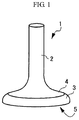
- An exhaust valve of a diesel engine is described below as one example of the present invention, by reference to FIG. 1 .
- an exhaust valve 1 is a diesel engine exhaust valve for a ship, which is made of an Ni-Cr-Al system Ni-base age-precipitated alloy having excellent high temperature corrosion resistance.
- the exhaust valve 1 contains a shaft part 2 and an umbrella part 3 that are integrated with each other, which is integrally formed by giving the umbrella part 3 to a tip of the rod-shaped shaft part 2 by forging or the like.
- the umbrella part 3 is provided with a face surface 4 having a curved surface at a side of the shaft part 2, and a fire contact surface 5 opposite thereto.
- the Ni-base age-precipitated alloy gives a layered structure (a lamellar structure) containing a layer formed of an ⁇ -Cr phase in crystal grains by a given aging heat treatment. Even in the exhaust valve 1, the layered structure containing a layer formed of an ⁇ -Cr phase having a thickness of 150 nm or more in crystal grains is observed as a whole. This is described below. In the peak of mechanical strength by the aging heat treatment, the thickness (width) of the layer formed of an ⁇ -Cr phase is about 150 nm. In other words, the exhaust valve 1 is in an overaged state and has hardness decreased from peak strength to 600 HV or less. Therefore, the shaft part 2 has machinability necessary for incorporating in an engine, and at the same time, the exhaust valve 1 achieves mechanical strength equivalent to or more than that of an exhaust valve made of Nimonic 80A while securing workability.
- the Ni-base age-precipitated alloy may have a component composition containing: Cr: 32 to 50%, Al: 0.5 to 10.0% and Fe: 0.1 to 20.0%, in mass %, in Ni.
- the Ni-base age-precipitated alloy contains Ni: 57%, Cr: 38%, Fe: 0.5% or less, and Al: 3.8%.
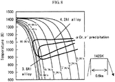
- the alloy exhibits a layered structure containing a layer formed of an ⁇ -Cr phase in crystal grains by an aging heat treatment at 930°C or lower, and can give predetermined mechanical strength as an exhaust valve when ⁇ '-phase has been precipitated and grown to make overaging.
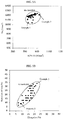
- the Ni-base age-precipitated alloy having the above-described component composition exhibits S attack resistance corrosion weight loss, which is an index of high temperature corrosion resistance, smaller than, for example, that of Nimonic 80A and Inconel 718, and comparable to that of Inconel 625.
- the Ni-base age-precipitated alloy having the above-described component composition exhibits V attach resistance corrosion weight loss smaller than that of each of those three alloys.
- S attach resistance and V attach resistance do not almost depend on hardness.
- the above component composition can contain optional addition elements without greatly inhibiting mechanical strength, corrosion resistance and the like, and this is described hereinafter.
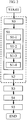
- FIGs. 2 , 3, 4A, 4B and 8 A method for manufacturing the above-described exhaust valve 1 is described below by reference to FIGs. 2 , 3, 4A, 4B and 8 .
- a steel ingot made of an Ni-base alloy having a predetermined component composition is melted in a vacuum induction furnace (S0).
- the steel ingot after melting is shaped with a mold before decreasing the temperature, and is conveyed while maintaining the temperature at 600°C or higher and placed in a heat equalizing furnace for rolling.
- conveying work may be conducted in a short period of time, or, for example, the steel ingot is covered with a sheet-shaped or box-shaped heat-insulating material made of a refractory such as ceramic fiber just after shaping with a mold, and suppressed the decrease of the temperature of a steel ingot surface during conveying to the heat equalizing furnace, thereby maintaining the temperature.
- a billet for forge working is produced therefrom by rolling (S1).
- a diameter of the billet is made larger than 100 mm.
- the steel ingot may be subjected to a heat equalizing treatment for the rolling in a heat equalizing furnace (S1-1).
- the steel ingot is typically heated and maintained at a temperature of 1,100°C or higher for 10 hours or more.
- the steel ingot is heated to 1,150°C.
- the steel ingot heated and maintained may be pre-rolled (S1-2).
- the steel ingot is subjected to blooming as necessary, and is rolled in a working amount smaller than that of main rolling described hereinafter. Subsequently, the pre-rolled steel ingot is subjected to hot surface grinding in order to remove scratches on the surface generated in the pre-rolling (S1-3).
- the steel ingot is then subjected to main rolling to obtain a billet (S1-4).
- the temperature is maintained higher than a forging completion temperature.
- the forging completion temperature is typically 800°C or higher, and is preferably about 850°C.
- the steel ingot may be reheated in the heat equalizing furnace as necessary in order to maintain the temperature.
- the circumference of the steel ingot or bloomed steel piece may be covered with a heat-insulting material such as ceramic fiber and conveyed to rolling facilities, or the rolling may be conducted in the form that the steel ingot or bloomed steel piece is covered with the heat-insulating material, thereby suppressing the decrease of a surface temperature of the steel ingot or bloomed steel piece during rolling.
- the temperature of the steel ingot is maintained at 600°C (873K) or higher to decrease temperature difference between a surface part and an inside, thereby preventing cracking of the steel ingot.
- ⁇ '-phase may be precipitated in the vicinity of the surface of the steel ingot.
- the precipitation of ⁇ '-phase is suppressed particularly in the inside of the steel ingot by suppressing the decrease of temperature as a whole steel ingot.
- the precipitation of ⁇ '-phase can be prevented in the heat equalizing treatment (S1-1) at a temperature of 1,100°C (1,373K) or higher, and the precipitation of ⁇ '-phase in the inside of a steel ingot or steel piece can be suppressed in the pre-rolling (S1-2), the surface grinding (S1-3) and the main rolling (S1-4), in all of which the temperature is maintained at 800°C (1,073K) or higher. Accordingly, the cracking of a steel ingot or steel piece can be prevented without excessively increasing deformation resistance during rolling. Furthermore, the cracking of a steel ingot or steel piece can be prevented also by the removal of scratches with the surface grinding (S1-3). The billet can be thus prepared.
- the billet prepared is subjected to an aging heat treatment (S2). If the billet is directly air-cooled, cracking tends to be generated. Therefore, it is preferred that the billet is directly maintained at a temperature of the aging heat treatment.
- the aging heat treatment is conducted while maintaining the temperature at 600°C or higher that is a temperature maintained from the melting step (S0) to the billeting step (S1) as described above, preferably at 800°C or higher that is a rolling completion temperature.
- the aging heat treatment is further conducted beyond a peak of mechanical strength (e.g., corresponding to hardness of about 700 HV) which is attained by age precipitation of reinforced particles ( ⁇ '-phase) in the age-precipitated alloy. That is, overaged state is formed.
- the hardness of the valve is adjusted to 600 HV or less by an adjusting heat treatment (S5) described below.
- a layered structure containing a layer formed of an ⁇ -Cr phase having a thickness of about 150 nm is observed in structure in crystal grains observed by cross-sectional observation in the billet at a peak of mechanical strength. Therefore, in the case where the aging heat treatment is conducted beyond this state, the thickness of the layer of ⁇ -Cr phase greatly grows.
- the aging heat treatment is typically conducted by maintaining the billet at about 850°C for about 16 hours, followed by air-cooling.
- a stepped round bar 1' is prepared by hot forging (rough forging) typically at a heating temperature of about 1,050°C (S3).
- the stepped round bar 1' is a bar-shaped product containing a round bar-shaped shaft part 2, a connecting part 2a having a diameter continuously increasing from the round bar-shaped shaft part 2, and a worked part 3' having a diameter larger than that of the shaft part 2 in the tip of the connecting part 2a.
- the stepped round bar 1' may be subjected to machining as necessary.
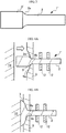
- the stepped round bar 1' is shaped and forge-worked typically at a heating temperature of about 1,050°C to deform the worked part 3', thereby giving an umbrella part 3, and is worked into nearly valve shape where the shaft part and the umbrella part are integrated (S4).
- a forging die 9 which has a worked surface 9a formed so as to correspond to a curved surface at a side of the face surface 4 of the umbrella part 3 of the exhaust valve 1 to be obtained is prepared.
- the shaft part 2 of the stepped round bar 1' is inserted in a central penetration hole 9b of the forging die 9 from a side of the worked surface 9a.
- the shaft part 2 is held by a holder 12, and is pushed until at least a part of the connecting part 2a comes into contact with the worked surface 9a of the forging die 9.
- FIG. 4A first, a forging die 9 which has a worked surface 9a formed so as to correspond to a curved surface at a side of the face surface 4 of the umbrella part 3 of the exhaust valve 1 to be obtained is prepared.
- the shaft part 2 of the stepped round bar 1' is inserted in a central penetration hole 9b of the forging die 9 from a side of the worked surface 9a.
- the shaft part 2 is held by a holder 12, and is
- the valve-shaped material obtained is placed in an external heating furnace and subjected to a heat treatment of typically maintaining at about 800°C for about 21 hours, followed by air-cooling, thereby performing an adjusting heat treatment for adjusting the structure, mainly hardness (S5).
- the valve-shaped material is subjected to overaging heat treatment in conjunction with the aging heat treatment (overaging treatment (S2)), that is, the valve-shaped material is softened until it reaches a mechanical strength exceeding its peak and reaches a predetermined hardness.
- the layered structure in crystal grains, containing a layer formed of an ⁇ -Cr phase having a thickness of 150 nm or more and obtained by the aging heat treatment (S2) is maintained.
- the predetermined hardness is 600 HV or less, and preferably from 380 HV to 430 HV.
- the valve-shaped material is maintained at about 1,050°C for about 1 hour, followed by water-cooling.
- exhaust valves 1 were manufactured by applying 4 kinds of heat treatment histories. That is, exhaust valves 1 were manufactured by previously conducting or not the solution heat treatment before the adjusting heat treatment (aging heat treatment (S5)), and in either case, conducting the adjusting heat treatment (aging heat treatment (S5)) by maintaining at 800°C for 16 hours or maintaining at 800°C for 21 hours.
- a tensile test piece was cut off along a longitudinal direction from the vicinity of an end of the shaft part 2 (a side opposite the umbrella part 3) of each exhaust valve 1, and additionally in Examples 1 and 2 described hereinafter, a tensile test piece was further cut off along a circumferential direction from the vicinity of an outer circumference of the umbrella part 3.
- Those test pieces were subjected to a tensile test at ordinary temperatures.
- a hardness test piece was cut off from a shoulder remaining material of each tensile test piece, and Brinell hardness and Vickers hardness of the hardness test piece were measured.
- Nimonic 80A typically has a 0.2% proof stress of 800 N/mm 2 or more, and a tensile strength of 1,200 N/mm 2 or more. Therefore, those values were used as target values of 0.2% proof stress and tensile strength in the tensile test. Further, considering machinability required in the shaft part, it is sufficient if elongation is 5% or more and reduction of area is 5% or more. The elongation is preferably 7% or more and the reduction of area is preferably 7% or more. Therefore, those values were used as target values. The elongation is more preferably 15% or more and the reduction of area is more preferably 25% or more.
- the target value of hardness was set as a range of from 380 to 430 HV as Vickers hardness and as 352 HBW or more as Brinell hardness, in order to achieve more preferably workability as a shaft part of an exhaust valve and additionally considering abrasion resistance as an umbrella part.
- the hardness can be adjusted to within a range of from 380 to 430 HV, and mechanical strength required as an exhaust valve can be obtained while securing preferable workability as a shaft part of an exhaust valve.
- the umbrella part 3 showed higher hardness (Vickers hardness) than that of the shaft part 2.
- the umbrella part 3 in Example 1 showed a hardness of 397 HV, which was higher than 390 HV of the shaft part 2.
- the umbrella part 3 in Example 2 showed a hardness of 425 HV, which was higher than 414 HV of the shaft part 2. The reason for this is considered that because shaping and forging are conducted in the umbrella part 3, hardness of the umbrella part 3 can be increased.
- the exhaust valves of Examples 1 and 2 were manufactured by isothermally holding the exhaust valves for 21 hours in the aging heat treatment of the adjusting heat treatment (S5). As for each of these exhaust valves of Examples 1 and 2, a high temperature tensile test piece was further cut off from the end of the shaft part 2 that was cut off from the tensile test piece, and was subjected to a high temperature tensile test. The test was conducted by holding the high temperature tensile test piece at 500°C for 20 minutes and then applying a load. The results of the high temperature tensile test are shown in Table 3. Table 3 No. Treatment condition 0.2% Proof stress Tensile strength Elongation Reduction of area (N/mm 2 ) (N/mm 2 ) (%) (%) Example 1 AG/21 755 1048 22 34 Example 2 ST-AG/21 936 1213 9 9 9
- the test results of Examples 1 and 2 were within the same degree of the variation range of the test results of the exhaust valve made of Nimonic 80A tested under the same conditions.
- the exhaust valves of Examples 1 and 2 showed 0.2% proof stress, tensile strength, elongation, and reduction of area, which are equivalent to or more than that of the exhaust valve made of Nimonic 80A.
- the exhaust valve made of Nimonic 80A showed 0.2% proof stress distributing in a range of from about 740 to 910 N/mm 2 , whereas the exhaust valves of Examples 1 and 2 showed 755 N/mm 2 and 936 N/mm 2 , respectively, which were equivalent to or more than that of the exhaust valve made of Nimonic 80A.
- the exhaust valve made of Nimonic 80A showed tensile strength distributing in a range of from about 1,040 to 1,240 N/mm 2
- the exhaust valves of Examples 1 and 2 showed 1,048 N/mm 2 and 1,213 N/mm 2 , respectively, which were equivalent to that of the exhaust valve made of Nimonic 80A.
- the exhaust valve made of Nimonic 80A showed elongation of distributing in a range of from about 7 to 21 %, whereas the exhaust valves of Examples 1 and 2 showed 22% and 9%, respectively, which were equivalent to or more than that of the exhaust valve made of Nimonic 80A. Additionally, the exhaust valve made of Nimonic 80A showed reduction of area distributing in a range of from about 7 to 33%, whereas the exhaust valves of Examples 1 and 2 showed 34% and 9%, respectively, which were equivalent to or more than that of the exhaust valve made of Nimonic 80A. In other words, it is understood that according to Examples 1 and 2, the exhaust valve of the present invention also achieves high temperature tensile strength equivalent to or more than that of the exhaust valve made of Nimonic 80A.
- FIG. 6A and FIG. 6B show SEM observation photographs of a sectional structure of the exhaust valve made of the alloy used in the Examples described above at the time when the exhaust valve reached peak mechanical strength, that is, when the hardness was about 700 HV
- the observation was performed on a surface formed by mirror-polishing the cut surface and etching the surface with 10% oxalic acid solution.
- a layered structure containing a layer formed of an ⁇ -Cr phase was observed in crystal grains, and the thickness of the ⁇ -Cr phase was about 150 nm.
- the exhaust valves in the examples described above had a layered structure containing a layer formed of an ⁇ -Cr phase grown to a thickness of 150 nm or more in crystal grains, and were in the state of a so-called "overaged".
- a hardness test piece was cut off from the umbrella part 3, and was subjected to a high temperature hardness test.
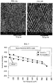
- a plurality of hardness test pieces were cut off from the vicinity of a face surface of the umbrella part 3 of the exhaust valve of Example 2, and they were maintained at 400°C for 100 hours considering use environment of an exhaust valve, followed by air-cooling. Thereafter, as shown in FIG. 7 , the test pieces maintained at the respective test temperatures were subjected to a hardness test.
- the exhaust valve made ofNimonic 80A was similarly subjected to the hardness test.
- the hardness test piece of Example 2 showed high temperature hardness equivalent to or more than that ofNimonic 80A at each test temperature. Accordingly, it is understood that the exhaust valve of the present invention can achieve high temperature hardness equivalent to or more than that ofNimonic 80A even after used in an engine for a large ship.
- the alloy used in the examples is excellent in S attack resistance and V attack resistance as compared with Nimonic 80A, Inconel 718 and Inconel 625, and have a sufficient high temperature corrosion resistance required as an exhaust valve.
- an integrated exhaust valve having required mechanical strength and high temperature corrosion resistance can be manufactured without conducting a partial working, for example, increasing hardness only in an umbrella part in the production process. That is, an easily manufacturable engine exhaust valve for a large ship can be obtained.
- the alloy may have a component composition containing, in mass %: essential elements of Cr: 32 to 50%, Al: 0.5 to 10.0%, and Fe: 0.1 to 20.0%; optional elements of Si: 5% or less, B: 0.01% or less, C: 0.1% or less, Cu: 5% or less, Ti: 0.1% or less, Nb: 0.1% or less, Ta: 0.1 % or less, and V: 0.1 % or less, with the proviso that Ti+Nb+Ta+V is 0.1 % or less, and the balance being unavoidable impurities and Ni. Cr, Al and Fe that are essential elements are described below.
- Cr forms an ⁇ -Cr phase and increases hardness, and additionally suppresses coarsening of crystal grains. Furthermore, Cr can increase high temperature corrosion resistance such as V attack resistance or S attack resistance in a certain addition range. On the other hand, in the case where Cr is excessively added, forging resistance is too increased to perform forge working. Considering those, Cr may be added in an amount of, in mass %, from 32 to 50%, and preferably from 35 to 45%.
- Al is an Ni-system intermetallic compound, forms ⁇ '-phase that is an age-hardening phase contributing to a strengthening mechanism in an Ni-base age-precipitated alloy, and can increase mechanical strength at high temperature. Furthermore, Al can increase high temperature corrosion resistance in a certain addition range. On the other hand, excessive precipitation of ⁇ '-phase accelerates brittleness. Considering those, Al may be added in an amount of, in mass %, from 0.5 to 10.0%, and preferably from 3.4 to 5.0%.
- Fe is added as a substitute of Ni. Fe accelerates precipitation of a layered structure containing a ⁇ '-phase finely precipitated in the inside of ⁇ -phase, together with ⁇ -Cr phase, and can shorten overaging treatment time and aging treatment time. On the other hand, in the case where the amount of Fe added is too large, high temperature corrosion resistance is deteriorated. Therefore, Fe may be added in an amount of, in mass %, from 0.1 to 20.0%, and preferably from 0.5 to 5%.
- the alloy may contain Si, B, C, Cu, Ti, Nb, Ta and V that are optional elements as described below.
- Si forms a particulate metal intermetallic compound giving influence to mechanical strength at high temperature, and can additionally improve corrosion resistance at high temperature.
- excessive precipitation of an intermetallic compound phase induces brittleness. Therefore, Si may be added in an amount of, in mass %, 5% or less, and preferably 3.5% or less.
- B gives influence to mechanical strength of a grain boundary.
- B may be added in an amount of, in mass %, 0.01% or less, and preferably 0.005% or less.
- C gives influence to corrosion resistance at high temperature, allows to precipitate a carbide between C and a predetermined element described below, and can give influence to mechanical strength.
- C may be added in an amount of, in mass %, 0.1% or less.
- Cu dissolves in an ⁇ -phase and gives influence to mechanical strength.
- Cu may be added in an amount of, in mass %, 5% or less, and preferably 1% or less.
- Each of Ti, Nb, Ta and V bonds to C to form a carbide gives influence to mechanical strength, and additionally gives influence to corrosion resistance at high temperature. It is preferred that Ti is added in an amount of, in mass %, 0.1% or less, Nb is added in an amount of, in mass %, 0.1% or less, and Ta is added in an amount of, in mass %, 0.1% or less, V is added in an amount of, in mass %, 0.1 % or less, with the proviso that Ti+Nb+Ta+V is 0.1% or less.
Landscapes
- Chemical & Material Sciences (AREA)
- Engineering & Computer Science (AREA)
- Mechanical Engineering (AREA)
- Materials Engineering (AREA)
- Metallurgy (AREA)
- Organic Chemistry (AREA)
- General Engineering & Computer Science (AREA)
- Heat Treatment Of Articles (AREA)
Applications Claiming Priority (2)
| Application Number | Priority Date | Filing Date | Title |
|---|---|---|---|
| JP2015012257 | 2015-01-26 | ||
| JP2015203272A JP6638308B2 (ja) | 2015-01-26 | 2015-10-14 | 大型船舶用エンジン排気バルブ及びその製造方法 |
Publications (2)
| Publication Number | Publication Date |
|---|---|
| EP3048178A1 true EP3048178A1 (de) | 2016-07-27 |
| EP3048178B1 EP3048178B1 (de) | 2017-08-16 |
Family
ID=55484806
Family Applications (1)
| Application Number | Title | Priority Date | Filing Date |
|---|---|---|---|
| EP16152651.2A Active EP3048178B1 (de) | 2015-01-26 | 2016-01-25 | Motorauslassventil für grosses schiff und verfahren zur herstellung davon |
Country Status (2)
| Country | Link |
|---|---|
| US (1) | US10557388B2 (de) |
| EP (1) | EP3048178B1 (de) |
Families Citing this family (1)
| Publication number | Priority date | Publication date | Assignee | Title |
|---|---|---|---|---|
| US20240141459A1 (en) * | 2022-10-31 | 2024-05-02 | Daido Steel Co., Ltd. | Ni-BASED ALLOY AND METHOD FOR MANUFACTURING THE SAME, AND Ni-BASED ALLOY MEMBER |
Citations (5)
| Publication number | Priority date | Publication date | Assignee | Title |
|---|---|---|---|---|
| CA1038655A (en) * | 1973-07-23 | 1978-09-19 | Donald R. Muzyka | Sulfidation resistant nickel-iron base alloy |
| EP0889207A1 (de) * | 1997-07-03 | 1999-01-07 | Daido Steel Company Limited | Verfahren zur Herstellung der Ventile einer Diesel-Brennkraftmaschine |
| JP2000328163A (ja) | 1999-05-21 | 2000-11-28 | Daido Steel Co Ltd | ディーゼルエンジン用排気バルブ合金及び排気バルブの製造方法 |
| WO2002092865A1 (de) * | 2001-05-15 | 2002-11-21 | Thyssenkrupp Vdm Gmbh | Austenitische warmfeste nickel-basis-legierung |
| JP2014169631A (ja) | 2013-03-01 | 2014-09-18 | Daido Steel Co Ltd | ディーゼルエンジン排気バルブの製造方法 |
Family Cites Families (12)
| Publication number | Priority date | Publication date | Assignee | Title |
|---|---|---|---|---|
| US3969109A (en) * | 1974-08-12 | 1976-07-13 | Armco Steel Corporation | Oxidation and sulfidation resistant austenitic stainless steel |
| US5458314A (en) | 1993-04-01 | 1995-10-17 | Eaton Corporation | Temperature control in an ultra light engine valve |
| US5413073A (en) | 1993-04-01 | 1995-05-09 | Eaton Corporation | Ultra light engine valve |
| US5660938A (en) * | 1993-08-19 | 1997-08-26 | Hitachi Metals, Ltd., | Fe-Ni-Cr-base superalloy, engine valve and knitted mesh supporter for exhaust gas catalyzer |
| US6491769B1 (en) * | 2000-01-24 | 2002-12-10 | Inco Alloys International, Inc. | Ni-Co-Cr high temperature strength and corrosion resistant alloy |
| JP2001234313A (ja) | 2000-02-23 | 2001-08-31 | Fuji Oozx Inc | チタン合金製エンジンバルブの製造方法 |
| JP3916484B2 (ja) | 2002-03-05 | 2007-05-16 | 独立行政法人科学技術振興機構 | 耐高温酸化性に優れたNi合金耐熱材料およびその製造方法 |
| CN101429608B (zh) | 2007-11-06 | 2010-09-29 | 江苏兴海特钢有限公司 | 排气阀用耐热合金的生产工艺 |
| JP2009263736A (ja) | 2008-04-27 | 2009-11-12 | Daido Steel Co Ltd | プラスチック樹脂成形金型用Ni基合金及びこれを用いたプラスチック樹脂成形金型 |
| JP2012045604A (ja) | 2010-08-30 | 2012-03-08 | Daido Steel Co Ltd | 船舶用エンジンバルブの製造方法 |
| DK177487B1 (en) | 2012-07-06 | 2013-07-15 | Man Diesel & Turbo Deutschland | An exhaust valve spindle for an exhaust valve in an internal combustion engine |
| JP5973903B2 (ja) * | 2012-12-21 | 2016-08-23 | 株式会社神戸製鋼所 | 耐水素脆性に優れた高強度ばね用鋼線およびその製造方法並びに高強度ばね |
-
2016
- 2016-01-21 US US15/003,641 patent/US10557388B2/en active Active
- 2016-01-25 EP EP16152651.2A patent/EP3048178B1/de active Active
Patent Citations (5)
| Publication number | Priority date | Publication date | Assignee | Title |
|---|---|---|---|---|
| CA1038655A (en) * | 1973-07-23 | 1978-09-19 | Donald R. Muzyka | Sulfidation resistant nickel-iron base alloy |
| EP0889207A1 (de) * | 1997-07-03 | 1999-01-07 | Daido Steel Company Limited | Verfahren zur Herstellung der Ventile einer Diesel-Brennkraftmaschine |
| JP2000328163A (ja) | 1999-05-21 | 2000-11-28 | Daido Steel Co Ltd | ディーゼルエンジン用排気バルブ合金及び排気バルブの製造方法 |
| WO2002092865A1 (de) * | 2001-05-15 | 2002-11-21 | Thyssenkrupp Vdm Gmbh | Austenitische warmfeste nickel-basis-legierung |
| JP2014169631A (ja) | 2013-03-01 | 2014-09-18 | Daido Steel Co Ltd | ディーゼルエンジン排気バルブの製造方法 |
Also Published As
| Publication number | Publication date |
|---|---|
| US10557388B2 (en) | 2020-02-11 |
| EP3048178B1 (de) | 2017-08-16 |
| US20160215660A1 (en) | 2016-07-28 |
Similar Documents
| Publication | Publication Date | Title |
|---|---|---|
| US8696836B2 (en) | Nonmagnetic high-hardness alloy | |
| EP3587606A1 (de) | N-basierte superwärmebeständige legierung und verfahren zur herstellung davon | |
| CN103348029B (zh) | 疲劳强度优异的耐磨损性钛合金构件 | |
| JP6011098B2 (ja) | 大型船舶用エンジン排気バルブの製造方法 | |
| EP3772544A1 (de) | Verfahren zur herstellung einer hochfeuerfesten legierung auf nickelbasis und hochfeuerfeste legierung auf nickelbasis | |
| JP4517095B2 (ja) | 高強度チタン合金製自動車用エンジンバルブ | |
| EP3276016B1 (de) | Alpha/beta-titanlegierung | |
| EP2540998A1 (de) | Fahrzeugmotorventil mit einer titanlegierung und hervorragender wärmebeständigkeit | |
| KR102062031B1 (ko) | 대형 선박용 엔진 배기 밸브 및 그 제조 방법 | |
| CN111819300B (zh) | 航空器发动机壳体用Ni基超耐热合金及由其制成的航空器发动机壳体 | |
| JP3580441B2 (ja) | Ni基超耐熱合金 | |
| JP5060083B2 (ja) | ピストンリングの製造方法 | |
| EP3048178B1 (de) | Motorauslassventil für grosses schiff und verfahren zur herstellung davon | |
| JP5437669B2 (ja) | 温熱間鍛造用金型 | |
| TWI512115B (zh) | 沃斯田鐵系合金鋼材之製造方法 | |
| JP2014169631A (ja) | ディーゼルエンジン排気バルブの製造方法 | |
| WO2014014069A1 (ja) | 大型船舶用エンジン排気バルブの製造方法 | |
| CN108699635B (zh) | 热锻性优异的高强度高耐腐蚀性Ni基合金 | |
| JP2017214870A (ja) | 内燃機関用ピストン及びその製造方法 | |
| JP3623313B2 (ja) | 浸炭歯車部品 | |
| JP2000204449A (ja) | 冷間加工性と高温加熱安定性に優れたFe基耐熱合金 | |
| JP6745050B2 (ja) | Ni基合金およびそれを用いた耐熱板材 | |
| JPH11199987A (ja) | 冷間加工に適した耐熱合金 | |
| JPH093577A (ja) | 熱間押出ダイス用材料およびその製造方法 | |
| JP2005314744A (ja) | ピストンリング用材料及びその材料を用いたピストンリング |
Legal Events
| Date | Code | Title | Description |
|---|---|---|---|
| PUAI | Public reference made under article 153(3) epc to a published international application that has entered the european phase |
Free format text: ORIGINAL CODE: 0009012 |
|
| AK | Designated contracting states |
Kind code of ref document: A1 Designated state(s): AL AT BE BG CH CY CZ DE DK EE ES FI FR GB GR HR HU IE IS IT LI LT LU LV MC MK MT NL NO PL PT RO RS SE SI SK SM TR |
|
| AX | Request for extension of the european patent |
Extension state: BA ME |
|
| 17P | Request for examination filed |
Effective date: 20161007 |
|
| RBV | Designated contracting states (corrected) |
Designated state(s): AL AT BE BG CH CY CZ DE DK EE ES FI FR GB GR HR HU IE IS IT LI LT LU LV MC MK MT NL NO PL PT RO RS SE SI SK SM TR |
|
| GRAP | Despatch of communication of intention to grant a patent |
Free format text: ORIGINAL CODE: EPIDOSNIGR1 |
|
| RIC1 | Information provided on ipc code assigned before grant |
Ipc: C22C 19/05 20060101AFI20170317BHEP |
|
| INTG | Intention to grant announced |
Effective date: 20170412 |
|
| GRAS | Grant fee paid |
Free format text: ORIGINAL CODE: EPIDOSNIGR3 |
|
| GRAA | (expected) grant |
Free format text: ORIGINAL CODE: 0009210 |
|
| AK | Designated contracting states |
Kind code of ref document: B1 Designated state(s): AL AT BE BG CH CY CZ DE DK EE ES FI FR GB GR HR HU IE IS IT LI LT LU LV MC MK MT NL NO PL PT RO RS SE SI SK SM TR |
|
| REG | Reference to a national code |
Ref country code: GB Ref legal event code: FG4D |
|
| REG | Reference to a national code |
Ref country code: CH Ref legal event code: EP |
|
| REG | Reference to a national code |
Ref country code: IE Ref legal event code: FG4D |
|
| REG | Reference to a national code |
Ref country code: AT Ref legal event code: REF Ref document number: 919100 Country of ref document: AT Kind code of ref document: T Effective date: 20170915 |
|
| REG | Reference to a national code |
Ref country code: DE Ref legal event code: R096 Ref document number: 602016000208 Country of ref document: DE |
|
| REG | Reference to a national code |
Ref country code: NL Ref legal event code: MP Effective date: 20170816 |
|
| REG | Reference to a national code |
Ref country code: NO Ref legal event code: T2 Effective date: 20170816 |
|
| REG | Reference to a national code |
Ref country code: LT Ref legal event code: MG4D |
|
| PG25 | Lapsed in a contracting state [announced via postgrant information from national office to epo] |
Ref country code: LT Free format text: LAPSE BECAUSE OF FAILURE TO SUBMIT A TRANSLATION OF THE DESCRIPTION OR TO PAY THE FEE WITHIN THE PRESCRIBED TIME-LIMIT Effective date: 20170816 Ref country code: NL Free format text: LAPSE BECAUSE OF FAILURE TO SUBMIT A TRANSLATION OF THE DESCRIPTION OR TO PAY THE FEE WITHIN THE PRESCRIBED TIME-LIMIT Effective date: 20170816 Ref country code: SE Free format text: LAPSE BECAUSE OF FAILURE TO SUBMIT A TRANSLATION OF THE DESCRIPTION OR TO PAY THE FEE WITHIN THE PRESCRIBED TIME-LIMIT Effective date: 20170816 Ref country code: FI Free format text: LAPSE BECAUSE OF FAILURE TO SUBMIT A TRANSLATION OF THE DESCRIPTION OR TO PAY THE FEE WITHIN THE PRESCRIBED TIME-LIMIT Effective date: 20170816 |
|
| PG25 | Lapsed in a contracting state [announced via postgrant information from national office to epo] |
Ref country code: ES Free format text: LAPSE BECAUSE OF FAILURE TO SUBMIT A TRANSLATION OF THE DESCRIPTION OR TO PAY THE FEE WITHIN THE PRESCRIBED TIME-LIMIT Effective date: 20170816 Ref country code: RS Free format text: LAPSE BECAUSE OF FAILURE TO SUBMIT A TRANSLATION OF THE DESCRIPTION OR TO PAY THE FEE WITHIN THE PRESCRIBED TIME-LIMIT Effective date: 20170816 Ref country code: GR Free format text: LAPSE BECAUSE OF FAILURE TO SUBMIT A TRANSLATION OF THE DESCRIPTION OR TO PAY THE FEE WITHIN THE PRESCRIBED TIME-LIMIT Effective date: 20171117 Ref country code: LV Free format text: LAPSE BECAUSE OF FAILURE TO SUBMIT A TRANSLATION OF THE DESCRIPTION OR TO PAY THE FEE WITHIN THE PRESCRIBED TIME-LIMIT Effective date: 20170816 Ref country code: BG Free format text: LAPSE BECAUSE OF FAILURE TO SUBMIT A TRANSLATION OF THE DESCRIPTION OR TO PAY THE FEE WITHIN THE PRESCRIBED TIME-LIMIT Effective date: 20171116 Ref country code: PL Free format text: LAPSE BECAUSE OF FAILURE TO SUBMIT A TRANSLATION OF THE DESCRIPTION OR TO PAY THE FEE WITHIN THE PRESCRIBED TIME-LIMIT Effective date: 20170816 Ref country code: IS Free format text: LAPSE BECAUSE OF FAILURE TO SUBMIT A TRANSLATION OF THE DESCRIPTION OR TO PAY THE FEE WITHIN THE PRESCRIBED TIME-LIMIT Effective date: 20171216 |
|
| PG25 | Lapsed in a contracting state [announced via postgrant information from national office to epo] |
Ref country code: RO Free format text: LAPSE BECAUSE OF FAILURE TO SUBMIT A TRANSLATION OF THE DESCRIPTION OR TO PAY THE FEE WITHIN THE PRESCRIBED TIME-LIMIT Effective date: 20170816 Ref country code: DK Free format text: LAPSE BECAUSE OF FAILURE TO SUBMIT A TRANSLATION OF THE DESCRIPTION OR TO PAY THE FEE WITHIN THE PRESCRIBED TIME-LIMIT Effective date: 20170816 Ref country code: CZ Free format text: LAPSE BECAUSE OF FAILURE TO SUBMIT A TRANSLATION OF THE DESCRIPTION OR TO PAY THE FEE WITHIN THE PRESCRIBED TIME-LIMIT Effective date: 20170816 |
|
| REG | Reference to a national code |
Ref country code: DE Ref legal event code: R097 Ref document number: 602016000208 Country of ref document: DE |
|
| PG25 | Lapsed in a contracting state [announced via postgrant information from national office to epo] |
Ref country code: EE Free format text: LAPSE BECAUSE OF FAILURE TO SUBMIT A TRANSLATION OF THE DESCRIPTION OR TO PAY THE FEE WITHIN THE PRESCRIBED TIME-LIMIT Effective date: 20170816 Ref country code: IT Free format text: LAPSE BECAUSE OF FAILURE TO SUBMIT A TRANSLATION OF THE DESCRIPTION OR TO PAY THE FEE WITHIN THE PRESCRIBED TIME-LIMIT Effective date: 20170816 Ref country code: SK Free format text: LAPSE BECAUSE OF FAILURE TO SUBMIT A TRANSLATION OF THE DESCRIPTION OR TO PAY THE FEE WITHIN THE PRESCRIBED TIME-LIMIT Effective date: 20170816 Ref country code: SM Free format text: LAPSE BECAUSE OF FAILURE TO SUBMIT A TRANSLATION OF THE DESCRIPTION OR TO PAY THE FEE WITHIN THE PRESCRIBED TIME-LIMIT Effective date: 20170816 |
|
| PLBE | No opposition filed within time limit |
Free format text: ORIGINAL CODE: 0009261 |
|
| STAA | Information on the status of an ep patent application or granted ep patent |
Free format text: STATUS: NO OPPOSITION FILED WITHIN TIME LIMIT |
|
| 26N | No opposition filed |
Effective date: 20180517 |
|
| REG | Reference to a national code |
Ref country code: DE Ref legal event code: R119 Ref document number: 602016000208 Country of ref document: DE |
|
| PG25 | Lapsed in a contracting state [announced via postgrant information from national office to epo] |
Ref country code: SI Free format text: LAPSE BECAUSE OF FAILURE TO SUBMIT A TRANSLATION OF THE DESCRIPTION OR TO PAY THE FEE WITHIN THE PRESCRIBED TIME-LIMIT Effective date: 20170816 |
|
| PG25 | Lapsed in a contracting state [announced via postgrant information from national office to epo] |
Ref country code: LU Free format text: LAPSE BECAUSE OF NON-PAYMENT OF DUE FEES Effective date: 20180125 Ref country code: FR Free format text: LAPSE BECAUSE OF NON-PAYMENT OF DUE FEES Effective date: 20180131 Ref country code: DE Free format text: LAPSE BECAUSE OF NON-PAYMENT OF DUE FEES Effective date: 20180801 |
|
| REG | Reference to a national code |
Ref country code: IE Ref legal event code: MM4A |
|
| REG | Reference to a national code |
Ref country code: FR Ref legal event code: ST Effective date: 20180928 |
|
| REG | Reference to a national code |
Ref country code: BE Ref legal event code: MM Effective date: 20180131 |
|
| PG25 | Lapsed in a contracting state [announced via postgrant information from national office to epo] |
Ref country code: BE Free format text: LAPSE BECAUSE OF NON-PAYMENT OF DUE FEES Effective date: 20180131 |
|
| PG25 | Lapsed in a contracting state [announced via postgrant information from national office to epo] |
Ref country code: IE Free format text: LAPSE BECAUSE OF NON-PAYMENT OF DUE FEES Effective date: 20180125 |
|
| PG25 | Lapsed in a contracting state [announced via postgrant information from national office to epo] |
Ref country code: MC Free format text: LAPSE BECAUSE OF FAILURE TO SUBMIT A TRANSLATION OF THE DESCRIPTION OR TO PAY THE FEE WITHIN THE PRESCRIBED TIME-LIMIT Effective date: 20170816 |
|
| REG | Reference to a national code |
Ref country code: CH Ref legal event code: PL |
|
| PG25 | Lapsed in a contracting state [announced via postgrant information from national office to epo] |
Ref country code: CH Free format text: LAPSE BECAUSE OF NON-PAYMENT OF DUE FEES Effective date: 20190131 Ref country code: LI Free format text: LAPSE BECAUSE OF NON-PAYMENT OF DUE FEES Effective date: 20190131 |
|
| PG25 | Lapsed in a contracting state [announced via postgrant information from national office to epo] |
Ref country code: MT Free format text: LAPSE BECAUSE OF NON-PAYMENT OF DUE FEES Effective date: 20180125 |
|
| PG25 | Lapsed in a contracting state [announced via postgrant information from national office to epo] |
Ref country code: TR Free format text: LAPSE BECAUSE OF FAILURE TO SUBMIT A TRANSLATION OF THE DESCRIPTION OR TO PAY THE FEE WITHIN THE PRESCRIBED TIME-LIMIT Effective date: 20170816 |
|
| PG25 | Lapsed in a contracting state [announced via postgrant information from national office to epo] |
Ref country code: PT Free format text: LAPSE BECAUSE OF FAILURE TO SUBMIT A TRANSLATION OF THE DESCRIPTION OR TO PAY THE FEE WITHIN THE PRESCRIBED TIME-LIMIT Effective date: 20170816 |
|
| PG25 | Lapsed in a contracting state [announced via postgrant information from national office to epo] |
Ref country code: MK Free format text: LAPSE BECAUSE OF NON-PAYMENT OF DUE FEES Effective date: 20170816 Ref country code: HR Free format text: LAPSE BECAUSE OF FAILURE TO SUBMIT A TRANSLATION OF THE DESCRIPTION OR TO PAY THE FEE WITHIN THE PRESCRIBED TIME-LIMIT Effective date: 20170816 Ref country code: HU Free format text: LAPSE BECAUSE OF FAILURE TO SUBMIT A TRANSLATION OF THE DESCRIPTION OR TO PAY THE FEE WITHIN THE PRESCRIBED TIME-LIMIT; INVALID AB INITIO Effective date: 20160125 Ref country code: CY Free format text: LAPSE BECAUSE OF FAILURE TO SUBMIT A TRANSLATION OF THE DESCRIPTION OR TO PAY THE FEE WITHIN THE PRESCRIBED TIME-LIMIT Effective date: 20170816 |
|
| PG25 | Lapsed in a contracting state [announced via postgrant information from national office to epo] |
Ref country code: AL Free format text: LAPSE BECAUSE OF FAILURE TO SUBMIT A TRANSLATION OF THE DESCRIPTION OR TO PAY THE FEE WITHIN THE PRESCRIBED TIME-LIMIT Effective date: 20170816 |
|
| GBPC | Gb: european patent ceased through non-payment of renewal fee |
Effective date: 20200125 |
|
| PG25 | Lapsed in a contracting state [announced via postgrant information from national office to epo] |
Ref country code: GB Free format text: LAPSE BECAUSE OF NON-PAYMENT OF DUE FEES Effective date: 20200125 |
|
| REG | Reference to a national code |
Ref country code: AT Ref legal event code: UEP Ref document number: 919100 Country of ref document: AT Kind code of ref document: T Effective date: 20170816 |
|
| PGFP | Annual fee paid to national office [announced via postgrant information from national office to epo] |
Ref country code: NO Payment date: 20230110 Year of fee payment: 8 |
|
| PGFP | Annual fee paid to national office [announced via postgrant information from national office to epo] |
Ref country code: AT Payment date: 20231227 Year of fee payment: 9 |