EP3045346A1 - Verstellbeschlag - Google Patents
Verstellbeschlag Download PDFInfo
- Publication number
- EP3045346A1 EP3045346A1 EP15190634.4A EP15190634A EP3045346A1 EP 3045346 A1 EP3045346 A1 EP 3045346A1 EP 15190634 A EP15190634 A EP 15190634A EP 3045346 A1 EP3045346 A1 EP 3045346A1
- Authority
- EP
- European Patent Office
- Prior art keywords
- fitting
- wheel
- eccentric
- adjustment fitting
- fitting part
- Prior art date
- Legal status (The legal status is an assumption and is not a legal conclusion. Google has not performed a legal analysis and makes no representation as to the accuracy of the status listed.)
- Granted
Links
Images
Classifications
-
- B—PERFORMING OPERATIONS; TRANSPORTING
- B60—VEHICLES IN GENERAL
- B60N—SEATS SPECIALLY ADAPTED FOR VEHICLES; VEHICLE PASSENGER ACCOMMODATION NOT OTHERWISE PROVIDED FOR
- B60N2/00—Seats specially adapted for vehicles; Arrangement or mounting of seats in vehicles
- B60N2/02—Seats specially adapted for vehicles; Arrangement or mounting of seats in vehicles the seat or part thereof being movable, e.g. adjustable
- B60N2/22—Seats specially adapted for vehicles; Arrangement or mounting of seats in vehicles the seat or part thereof being movable, e.g. adjustable the back-rest being adjustable
- B60N2/225—Seats specially adapted for vehicles; Arrangement or mounting of seats in vehicles the seat or part thereof being movable, e.g. adjustable the back-rest being adjustable by cycloidal or planetary mechanisms
- B60N2/2252—Seats specially adapted for vehicles; Arrangement or mounting of seats in vehicles the seat or part thereof being movable, e.g. adjustable the back-rest being adjustable by cycloidal or planetary mechanisms in which the central axis of the gearing lies inside the periphery of an orbital gear, e.g. one gear without sun gear
-
- B—PERFORMING OPERATIONS; TRANSPORTING
- B60—VEHICLES IN GENERAL
- B60N—SEATS SPECIALLY ADAPTED FOR VEHICLES; VEHICLE PASSENGER ACCOMMODATION NOT OTHERWISE PROVIDED FOR
- B60N2/00—Seats specially adapted for vehicles; Arrangement or mounting of seats in vehicles
- B60N2/02—Seats specially adapted for vehicles; Arrangement or mounting of seats in vehicles the seat or part thereof being movable, e.g. adjustable
- B60N2/22—Seats specially adapted for vehicles; Arrangement or mounting of seats in vehicles the seat or part thereof being movable, e.g. adjustable the back-rest being adjustable
-
- Y—GENERAL TAGGING OF NEW TECHNOLOGICAL DEVELOPMENTS; GENERAL TAGGING OF CROSS-SECTIONAL TECHNOLOGIES SPANNING OVER SEVERAL SECTIONS OF THE IPC; TECHNICAL SUBJECTS COVERED BY FORMER USPC CROSS-REFERENCE ART COLLECTIONS [XRACs] AND DIGESTS
- Y10—TECHNICAL SUBJECTS COVERED BY FORMER USPC
- Y10T—TECHNICAL SUBJECTS COVERED BY FORMER US CLASSIFICATION
- Y10T74/00—Machine element or mechanism
- Y10T74/18—Mechanical movements
- Y10T74/18056—Rotary to or from reciprocating or oscillating
- Y10T74/18296—Cam and slide
- Y10T74/18336—Wabbler type
Definitions
- the invention relates to an adjustment fitting, in particular for a vehicle seat, with a first fitting part and a second fitting part rotatable relative to the first fitting part about an axis of rotation, wherein the first fitting part is associated with an external gear, in which an inner wheel associated with the second fitting part External toothing is used in the manner of a wobble mechanism, and wherein the inner wheel to the rotation axis forms an eccentric receiving space, with a rotatably inserted into the eccentric receiving space eccentric and with a drive shaft for driving the eccentric.
- the first fitting part and the second fitting part are assembled in the manner of a wobble mechanism, wherein when driving the eccentric, the inner wheel wobbles about its outer toothing on the inner toothing of the outer wheel.
- the number of teeth of the external teeth is different from the number of teeth of the internal teeth.
- An adjustment fitting with wobble gear has prevailed in vehicle technology for adjusting the backrest relative to the seat bottom of a vehicle seat.
- a wobble mechanism can be realized with comparatively few mechanical components and, with a flat construction at the same time, permits a translation desired for the adjustment.
- An adjustment fitting of the type mentioned is, for example, from the DE 10 2005 053 312 B3 , from the DE 101 44 840 B4 or from the DE 10 2005 056 728 B3 known.
- an adjustment fitting is used before it is used by means of a dip-coating method, in particular by means of a cathodic dip-coating method, coated with varnish to achieve a higher corrosion resistance.
- a dip-coating method in particular by means of a cathodic dip-coating method, coated with varnish to achieve a higher corrosion resistance.
- penetration of the paint into the interior of the fitting should be avoided, since penetrated paint can undesirably act on the transmission forming mechanical parts. Under certain circumstances, this can lead to a loss of function of the adjustment fitting.
- the object of the invention is to provide a Verstellbeschlag the aforementioned type, which allows for an improved sealing of the eccentric receiving space easier connection of an adapter.
- the inner wheel comprises an inner wall extended in the axial direction beyond the outer toothing.
- the eccentric receiving space is preferably sealed by a flat, a fitting resting on the cap, which is against the fitting under an axial bias.
- the cap is formed eccentric to the axis of rotation, it can dive with a pulled-down sealing edge in the interior of the eccentric receiving space and seal it under a radial bias.
- the cap is in this case adapted substantially in shape to the circumference of the receiving space.
- the cap is as a relative to the axis of rotation eccentrically offset disc educated.
- the standing under a radially outward biasing sealing edge which may be formed in particular as a contoured sealing lip, forms both a static seal in the case of a paint and a dynamic seal in the event of actuation of the adjustment. In the latter case, the sealing edge slides along the inside of the eccentric receiving space.
- the present-mentioned cap dips against this with the axially aligned sealing edge in the eccentric receiving space, so that with a corresponding length of the sealing edge easily with a single cap different axial heights of Verstellbeschlags or different thicknesses of the adapter are compensated without sacrificing the tightness.
- the radial seal is not affected by an axial offset. The invention thus offers the possibility of reducing the variety of variants, which is associated with a not inconsiderable cost savings.
- the cap and the sealing edge are preferably made of plastic.
- the sealing edge of the cap in particular by means of a two-component injection molding, molded.
- the sealing edge is captively connected to the cap.
- a material for the sealing edge is basically any elastomer, as long as it is sufficiently dimensionally stable and in particular withstands a cathodic dip painting.
- the material should be temperatures up to about Withstand 200 ° C.
- the material is a suitable plastic or rubber conceivable.
- a polyamide is used as the material for the sealing edge.
- the sealing edge dips into the extended inner wall and seals the receiving space under a radial pretension directed against the inner wall.
- the receiving space is thus sealed by means of the pressed against the inner wall (also referred to in the jargon passageway) of the inner wheel sealing edge to the outside.
- the drive shaft is formed as a continuous journal.
- a journal also offers the possibility to hold together the components of the adjustable fitting in the axial direction.
- the cap and the bearing pin are integrally formed.
- Such a one-piece design is now possible because the sealing of the receiving space takes place in the radial direction. Due to the one-piece design, the production costs are further reduced. Also, the installation of the adjustment fitting is simplified.
- the outer wheel comprises a bottom with a central bore in which the bearing journal is mounted, wherein the bearing pin is held against the ground with a lock washer, and wherein the lock washer comprises a sealing edge, the radial gap between the Bearing journal and the bottom under a directed axially against the ground bias.
- the lock washer thus acts as a cover of the "back" of the adjustment because it covers the rear radial gap between the bearing pin and the bottom of the outer wheel. Since the lock washer holds the adjustment fitting, this is advantageously by a reinforcing element, in particular a stored Steel element, mechanically supported.
- the sealing edge of the lock washer can again consist of a suitable elastomer.
- the bottom is sunken plate-shaped on the sides facing the lock washer. On the one hand, this reduces the axial height of the adjustment fitting. On the other hand, this ensures a secure rear sealing of the receiving space.
- For a stable storage of the soil comprises a bore surrounding the collar, in which the journal is mounted. About the enlarged in the axial direction bearing surface of the collar tensioning the bearing of the journal is stabilized. In particular, a tilting of the journal is reliably avoided.
- a central seal is inserted into the axial gap between the fitting parts.
- This idea is based on the previous practice to provide permanent caps for sealing the open axial access to the interior, and to use for the sealing of gaps of the adjustable fitting, which also provide access to the receiving space, against the ingress of paint grease.
- a contamination of the interior of the adjustment fitting with rinsing liquid may already occur during the pretreatment of the adjustment fitting.
- During the dip coating itself can then undesirably be rinsed grease, so that nevertheless can penetrate paint.
- leaked grease leads to quality losses during the painting process.
- only "paint-compatible" grease can be used in the fitting, which is associated with cost disadvantages.
- the axial gap necessary for relative rotation between the fitting parts which inevitably forms an access to the eccentric receiving space of the adjustment fitting, is suitable for a permanent seal. If a central seal is inserted into the axial gap between the first and the second fitting part, the access to the outer annular space between the inner wheel and the outer wheel is sealed off. Ingress of dirt and especially of paint during the painting process Over the outer annular space between the inner wheel and the outer wheel is thus safely and permanently prevented without the described problem of sealing by means of grease occurs.
- the fittings slide along with an adjustment of the fitting of the central seal along.
- the central seal thus acts both as a static and as a dynamic seal.
- the invention thus has a possibility to achieve a further sealing of the gear parts of the adjustment fitting to securely prevent the ingress of dirt and in particular paint during the painting process in the receiving space.
- a material for the central seal is basically any elastomer, as long as it is sufficiently dimensionally stable and in particular withstands a cathodic dip painting. In particular, the material should withstand temperatures up to about 200 ° C.
- the material is a suitable plastic or rubber conceivable.
- a polyamide is used as the material for the central seal.
- the central seal can completely fill a part of the axial gap or this.
- an adapter plate is preferably connected to the inner wall of the inner wheel circumferentially, which is spaced with an axial gap from the outer wheel.
- the central seal is inserted into the axial gap between the adapter and the outer wheel.
- the central seal is disc-shaped with an outer sealing edge, wherein the outer sealing edge has a substantially Y-shaped cross-section with radially outwardly directed and axially diverging legs, extending between the first and the second fitting part, in particular between the Outer wheel and the adapter, spread.
- the outer wheel comprises an outer wall which extends in the axial direction beyond the inner toothing and which engages over the outer toothing of the inner wheel with a radially inwardly directed collar, wherein the central seal has an inner axial sealing edge which is inserted into the collar.
- the extended outer wall and the overlap on the outer toothing of the inner wheel can be done in particular by a two-part design of the outer wheel.
- the outer wheel is divided at the internal toothing, so that, as it were, an upper and a lower shell arise. Between the upper and lower shell then the outer toothing of the inner wheel is securely stored or guided.
- the overlap in the extended outer wall can also take place by means of a holding element, which tracks the inner toothing of the inner wheel in the axial direction in the outer wall of the outer wheel and connected at the corresponding position with the outer wall, in particular welded. This provides the additional possibility of adjusting the axial clearance between the inner and the outer wheel.
- the central seal With the inner axial sealing edge, the central seal is then inserted into the outer wall of the outer wheel. This prevents twisting and slipping of the central seal with respect to the outer wheel.
- the assembly is simplified as a result.
- the inner axial sealing edge of the central seal runs in a radially inwardly curved end. In this way, the toothed area is additionally protected against spatter.
- the outer wheel on a separately inserted dome which carries the circumferential collar of the bottom of the outer wheel, wherein between the collar and the inner elongated inner wall of the eccentric receiving space is formed.
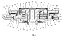
- FIG. 1 shows in a cross section an adjustment fitting with a seal of the eccentric receiving space.
- a Verstellbeschlag 1 comprising a first fitting part 2 and a second fitting part 3, which are rotatable relative to each other about an axis of rotation.
- the first fitting part 2 consists of an outer wheel 4, which is connected to the later assembly of a seat back, a corresponding backrest adapter 6, in particular by means of a weld.
- the second fitting part 3 comprises an inner wheel 7 and a seat adapter 8 connected thereto for connection to a seat base.
- the outer wheel 4 is formed as a ring gear with a bottom 9 and an outer wall 10, wherein on the outer wall 10, an internal toothing 12 is mounted.
- the outer wheel 4 is divided along the internal teeth 12 and composed of a first shell 13 and a second shell 14.
- the second shell 14 engages with a circumferential collar 15 which is a raised inner wall 16 of the inner wheel 7 mounted external teeth 17.
- the outer wheel 4 has a separately inserted dome 20, which carries a circumferential collar 21.
- the design of a separate dome 20 offers the possibility to optimize the different tribological properties with respect to storage and gearbox by appropriate choice of material.
- an eccentric, annular receiving space 24 is formed, in which a first Operazzenter 26 and a second Partzzenter 27 are used to drive the inner wheel 7.
- the two parts eccentric 26,27 form under rotation a variable total eccentricity, and are biased by a spring member 30 to form a maximum total eccentricity.
- the inner wheel 7 with its outer toothing 17 in the direction the largest eccentricity against the internal teeth 12 of the outer wheel 4 is pressed without play, so that a drainage of the fitting parts 2.3 to each other is not possible.
- a drive plate 31 is further inserted into the eccentric receiving space 24, engage in the driving lugs 33 of the respective parts eccentric 26,27.
- the drive plate 31 is rotatably connected to the central drive shaft 34, which is presently designed as a continuous bearing pin 35. If the bearing pin 35 is driven or rotated, the parts eccentric 26,27 are rotated against the bias of the spring member 30 via the rotatably connected drive plate 31, so that now the inner wheel 7 rests the outer wheel 4 under play.
- the existing from the Operaxzentern 26,27 total eccentric can be rotated, with the inner wheel 7 rolls over its outer teeth 17 on the inner teeth 12 of the outer wheel 4. In a full rotation of the eccentric there is a relative rotation of the inner wheel 7 relative to the outer wheel 4 corresponding to a tooth difference between the outer toothing 17 and the inner toothing 12th
- this has on its upper side a square opening 36.
- a receptacle for a further shaft is provided, which is optionally provided for driving a corresponding adjustment fitting on the other side of the vehicle seat.
- a plain bearing bush 37 is inserted into the inner circumference of the inner wheel 7.
- the bearing pin 35 is formed integrally with a cap 38 which seals the eccentric receiving space 24 to the outside.
- the cap 38 is disc-shaped and offset radially relative to the drive shaft 34. In other words, the cap 38 is eccentric.
- the eccentric cap 38 further comprises an axially pulled down sealing edge 40, which dips into the eccentric receiving space 24. Via a radially outwardly directed bias against the inner wall 16 of the inner wheel 7, the circumferential sealing edge 40 seals the eccentric receiving space 24 to the outside.
- the sealing edge 40 is made of a sprayable elastomer and the bearing pin 35 molded by means of a two-component injection molding process.
- the axial length of the sealing edge 40 is dimensioned so that with one and the same bearing pin 35 different variants of the adjustment fitting 1, which differ in the axial height, seals.
- An axial offset of the sealing rim 40 with respect to the inner wall 16 within a certain frame does not change the sealing function. In particular, this also applies to the case that the axial sealing edge 40 does not seal against the inner wall 16 of the inner wheel 7 but directly against a peripheral edge of the seat adapter 8.
- a lock washer 43 On the side facing away from the cap 38 of the bearing pin 35 is held by means of a lock washer 43 on the adjustment fitting 1.
- the axial cohesion of the fitting parts 2, 3 is accomplished by the outer wheel 4 designed as a ring gear.
- the lock washer 43 has a circumferential sealing edge 44 and is held in a dish-shaped recess 47 of the bottom 9 and the separate dome 20. Via a clip connection of the locking washer 43 on the bearing pin 35, an axial prestress of the sealing edge 44 relative to the bottom 9 is achieved.
- the lock washer 43 thus not only holds the bearing pin 35 in the adjustment fitting 1, but also seals the radial gap between the bearing pin 35 and the dome 20 from. Also on this page thus penetration of dirt or penetration of paint during the painting process is reliably prevented.
- the seat adapter 8 is connected in the form of a seat adapter sheet circumferentially of the inner wall 16 of the inner edge 7, in particular welded.
- the backrest adapter 6 is axially spaced from the outer wheel 4, to allow relative rotation to each other.
- a disk-shaped central seal 50 is further used. In this way, the interior of the adjustable fitting 1 completely sealed to the outside. Even over the outer annular gap between the inner wheel 7 and the outer wheel 4 can get neither dirt nor paint in the inner gear part.
- the disc-shaped central seal 50 further has an outer sealing edge 52 with a substantially Y-shaped cross-section.
- the two legs 53,54 of the outer sealing edge 52 extend radially outward and spread axially against the seat adapter 8 and against the outer wheel 4 from. In this way, both dirt and in particular paint is reliably prevented from penetrating into the interior of the adjustment fitting 1 via the axial gap 48.
- the central seal 50 has an inner axial sealing edge 57, with which it is inserted into the collar 15 of the outer wheel 4. As a result, a rotation of the central seal 50 with respect to the outer wheel 4 is prevented.
- the inner sealing edge 57 has an inwardly curved end 58. As a result, the inner gear of the adjustment fitting 1 is protected during the manufacturing process from spatter.
Landscapes
- Engineering & Computer Science (AREA)
- Aviation & Aerospace Engineering (AREA)
- Transportation (AREA)
- Mechanical Engineering (AREA)
- Chairs For Special Purposes, Such As Reclining Chairs (AREA)
- Transmission Devices (AREA)
- Seats For Vehicles (AREA)
Abstract
Description
- Die Erfindung betrifft einen Verstellbeschlag, insbesondere für einen Fahrzeugsitz, mit einem ersten Beschlagteil und einem relativ zum ersten Beschlagteil um eine Drehachse drehverstellbaren zweiten Beschlagteil, wobei dem ersten Beschlagteil ein Außenrad mit einer Innenverzahnung zugeordnet ist, in welches ein dem zweiten Beschlagteil zugeordnetes Innenrad mit einer Außenverzahnung nach Art eines Taumelgetriebes eingesetzt ist, und wobei das Innenrad zur Drehachse einen exzentrischen Aufnahmeraum bildet, mit einem in den exzentrischen Aufnahmeraum drehbar eingesetzten Exzenter und mit einer Antriebswelle zum Antrieb des Exzenters.
- Bei einem derartigen Verstellbeschlag sind das erste Beschlagteil und das zweite Beschlagteil nach Art eines Taumelgetriebes zusammengefügt, wobei sich bei Antrieb des Exzenters das Innenrad taumelnd über seine Außenverzahnung an der Innenverzahnung des Außenrads abrollt. Die Anzahl der Zähne der Außenverzahnung ist von der Anzahl der Zähne der Innenverzahnung verschieden. Bei einem vollständigen Umlauf des Exzenters resultiert eine Relativdrehung des Innenrads gegenüber dem Außenrad um die Zahndifferenz. Ein Verstellbeschlag mit Taumelgetriebe hat sich in der Fahrzeugtechnik zur Verstellung der Lehne gegenüber dem Sitzunterteil eines Fahrzeugsitzes durchgesetzt. Ein Taumelgetriebe ist mit vergleichsweise wenigen mechanischen Bauteilen zu verwirklichen und ermöglicht bei zugleich flacher Bauweise eine zur Verstellung gewünschte Übersetzung.
- Ein Verstellbeschlag der eingangs genannten Art ist beispielsweise aus der
DE 10 2005 053 312 B3 , aus derDE 101 44 840 B4 oder aus derDE 10 2005 056 728 B3 bekannt. - Üblicherweise wird ein Verstellbeschlag vor seinem Einsatz mittels eines Tauchlackier-Verfahrens, insbesondere mittels eines kathodischen Tauchlackier-Verfahrens, mit Lack beschichtet, um eine höhere Korrosionsbeständigkeit zu erzielen. Dabei sollte ein Eindringen des Lackes in das Innere des Beschlages vermieden werden, da eingedrungener Lack unerwünschterweise die das Getriebe bildenden mechanischen Teile beaufschlagen kann. Unter Umständen kann dies zu einer Funktionseinbuße des Verstellbeschlags führen.
- Aufgabe der Erfindung ist es, einen Verstellbeschlag der eingangs genannten Art anzugeben, der bei einer verbesserten Abdichtung des exzentrischen Aufnahmeraums eine einfachere Anbindung eines Adapters erlaubt.
- Diese Aufgabe wird erfindungsgemäß durch einen Verstellbeschlag mit der Merkmalskombination gemäß Anspruch 1 gelöst. Demnach umfasst das Innenrad eine in axialer Richtung über die Außenverzahnung hinaus verlängerte Innenwand.
- Durch das Vorsehen einer solchen Innenwand ist eine besonders leichte Anbindung eines Adapters ermöglicht, da das Innenrad hierdurch sehr leicht zugänglich wird. Zudem bietet diese konstruktive Ausgestaltung eine weitere Möglichkeit, unabhängig von den für verschiedene Fahrzeugsitze notwendigen Adaptern zu werden. Die über die Außenverzahnung hinaus verlängerte Innenwand bietet den weiteren Vorteil, dass der Adapter zur Befestigung in axialer Richtung verschoben werden kann. Auch dies ermöglicht eine kundenspezifische Variation des Verstellbeschlags, ohne dass dessen Bauteile variantenspezifisch adaptiert werden müssten.
- Der exzentrische Aufnahmeraum wird bevorzugt durch eine flach einem Beschlagteil aufliegende Abdeckkappe abgedichtet, die gegen das Beschlagteil unter einer axialen Vorspannung steht. Dadurch, dass die Abdeckkappe zur Drehachse exzentrisch ausgebildet ist, kann sie mit einem herabgezogenen Dichtrand in das Innere des exzentrischen Aufnahmeraums eintauchen und diesen unter einer radialen Vorspannung abdichten. Die Abdeckkappe ist hierbei in ihrer Form im Wesentlichen dem Umfang des Aufnahmeraums angeglichen. Insbesondere ist die Abdeckkappe als eine gegenüber der Drehachse exzentrisch versetzte Scheibe ausgebildet. Der unter einer radial nach außen gerichteten Vorspannung stehende Dichtrand, der insbesondere als eine mit einer Kontur ausgestattete Dichtlippe ausgebildet sein kann, bildet sowohl eine statische Dichtung im Falle einer Lackierung als auch eine dynamische Dichtung im Falle einer Betätigung des Verstellbeschlags. Im letzteren Fall gleitet der Dichtrand der Innenseite des exzentrischen Aufnahmeraums entlang.
- Dadurch, dass von einer axialen Vorspannung der Abdeckkappe gegen ein Beschlagteil Abstand genommen ist, bedarf es zur Abdichtung keiner Clips- oder Rastmechanik, mit der die Abdeckkappe beispielsweise an der Antriebswelle zur Ausbildung der axialen Vorspannung gegengelagert wird. Eine variantenspezifische Anpassung der Abdeckkappe im Falle von unterschiedlichen axialen Höhen des Verstellbeschlags ist nicht erforderlich, was beispielsweise durch unterschiedlich dicke Adapter bewirkt sein kann. Im Falle einer mittels axialer Vorspannung abdichtenden Abdeckkappe muss diese variantenspezifisch hergestellt werden, um gegen verschieden dicke Adapter abzudichten, die dem Außen- oder dem Innenrad angebunden sind. Die vorliegend genannte Abdeckkappe taucht hiergegen mit der axial ausgerichteten Dichtkante in den exzentrischen Aufnahmeraum hinein, so dass bei entsprechender Länge der Dichtkante problemlos mit einer einzigen Abdeckkappe unterschiedliche axiale Höhen des Verstellbeschlags bzw. unterschiedliche Dicken der Adapter ohne Einbußen der Dichtheit ausgeglichen werden. Die radiale Dichtung wird von einem axialen Versatz nicht berührt. Die Erfindung bietet insofern die Möglichkeit einer Verringerung der Variantenvielfalt, was mit einer nicht unbeachtlichen Kosteneinsparung verbunden ist.
- Die Abdeckkappe und der Dichtrand sind vorzugsweise aus Kunststoff gefertigt. Bevorzugt ist hierbei der Dichtrand der Abdeckkappe, insbesondere mittels eines Zwei-Komponenten-Spritzverfahrens, angespritzt. Dadurch wird der Dichtrand unverlierbar mit der Abdeckkappe verbunden.
- Als Material für den Dichtrand eignet sich grundsätzlich jedes Elastomer, solange es genügend formbeständig ist und insbesondere einem kathodischen Tauchlackierverfahren standhält. Insbesondere sollte das Material Temperaturen bis etwa 200°C standhalten. Als Material ist ein geeigneter Kunststoff oder Gummi vorstellbar. Bevorzugt wird als Material für den Dichtrand ein Polyamid eingesetzt.
- In einer bevorzugten Variante taucht der Dichtrand in die verlängerte Innenwand ein und dichtet den Aufnahmeraum unter einer gegen die Innenwand gerichteten radialen Vorspannung ab. Der Aufnahmeraum wird also mittels der gegen die Innenwand (im Fachjargon auch Durchzug genannt) des Innenrads gepresste Dichtkante nach außen abgedichtet.
- Vorteilhafterweise ist die Antriebswelle als ein durchgehender Lagerzapfen ausgebildet. Hierdurch wird die Montage des Verstellbeschlags erleichtert. Ein solcher Lagerzapfen bietet zudem die Möglichkeit, die Bauteile des Verstellbeschlags in axialer Richtung zusammenzuhalten.
- Bevorzugt sind die Abdeckkappe und der Lagerzapfen einstückig ausgebildet. Gegenüber bekannten Abdeckkappen gemäß Stand der Technik entfällt bei dieser Ausgestaltung eine notwendige Anbindung der Abdeckkappe an einem Verstellglied, insbesondere eine Verclipsung oder eine Verrastung. Eine solche einstückige Ausgestaltung ist nunmehr ermöglicht, da die Abdichtung des Aufnahmeraums in radialer Richtung erfolgt. Durch die einstückige Ausgestaltung sind weiter die Herstellkosten verringert. Ebenfalls ist die Montage des Verstellbeschlags vereinfacht.
- In einer weiter bevorzugten Ausgestaltung des Verstellbeschlags umfasst das Außenrad einen Boden mit einer zentralen Bohrung, in der der Lagerzapfen gelagert ist, wobei der Lagerzapfen gegen den Boden mit einer Sicherungsscheibe gehalten ist, und wobei die Sicherungsscheibe einen Dichtrand umfasst, der den radialen Spalt zwischen dem Lagerzapfen und dem Boden unter einer axial gegen den Boden gerichteten Vorspannung abdeckt. Die Sicherungsscheibe wirkt demnach als Abdeckung der "Rückseite" des Verstellbeschlags, da sie den rückwärtigen radialen Spalt zwischen dem Lagerzapfen und dem Boden des Außenrads abdeckt. Da die Sicherungsscheibe den Verstellbeschlag hält, ist diese vorteilhafterweise durch ein Verstärkungselement, insbesondere ein eingelagertes Stahlelement, mechanisch gestützt. Der Dichtrand der Sicherungsscheibe kann wieder aus einem geeigneten Elastomer bestehen.
- Bevorzugt ist der Boden auf der der Sicherungsscheibe zugewandten Seiten tellerförmig eingesenkt. Zum einen wird hierdurch die axiale Höhe des Verstellbeschlags verringert. Zum anderen ist hierdurch eine sichere rückwärtige Abdichtung des Aufnahmeraums sichergestellt.
- Für eine stabile Lagerung umfasst der Boden einen die Bohrung umlaufenden Kragenzug, in dem der Lagerzapfen gelagert ist. Über die in axialer Richtung vergrößerte Auflagefläche des Kragenzugs wird die Lagerung des Lagerzapfens stabilisiert. Insbesondere wird ein Verkippen des Lagerzapfens sicher vermieden.
- In einer auch eigenständig erfinderischen Ausgestaltung ist in den Axialspalt zwischen den Beschlagteilen eine Zentraldichtung eingesetzt. Diese Idee geht von der bisherigen Praxis aus, dauerhafte Abdeckkappen zur Abdichtung der offenen axialen Zugänge zum Innenraum vorzusehen, und für die Abdichtung von Spalten des Verstellbeschlags, die ebenfalls einen Zugang zum Aufnahmeraum bilden, gegen das Eindringen von Lack Fett zu verwenden. Bei dieser Praxis kann es aber bei der Vorbehandlung des Verstellbeschlags bereits zu einer Kontamination des Innenraums des Verstellbeschlags mit Spülflüssigkeit kommen. Während der Tauchlackierung selbst kann dann unerwünschterweise Fett ausgespült werden, so dass dennoch Lack eindringen kann. Zudem führt ausgetretenes Fett zu Qualitätseinbußen beim Lackierprozess. Ferner kann im Beschlag nur "lackverträgliches" Fett eingesetzt werden, was mit Kostennachteilen verbunden ist.
- Es wird nun erkannt, dass sich der zur Relativdrehung notwendige Axialspalt zwischen den Beschlagteilen, der zwangsläufig einen Zugang zum exzentrischen Aufnahmeraum des Verstellbeschlags bildet, für eine dauerhafte Abdichtung eignet. Wird in den Axialspalt zwischen dem ersten und dem zweiten Beschlagteil eine Zentraldichtung eingesetzt, so wird der Zugang zu dem äußeren Ringraum zwischen dem Innenrad und dem Außenrad dichtend abgeschlossen. Ein Eindringen von Schmutz und insbesondere von Lack während des Lackierprozesses über den äußeren Ringraum zwischen dem Innenrad und dem Außenrad ist somit sicher und dauerhaft verhindert, ohne dass die geschilderte Problematik einer Abdichtung mittels Fett auftritt. Die Beschlagteile gleiten dabei bei einer Verstellung des Beschlags der Zentraldichtung entlang. Die Zentraldichtung wirkt somit gleichermaßen als statische wie als dynamische Dichtung. Die Erfindung weist somit eine Möglichkeit auf, eine weitergehende Abdichtung der Getriebeteile des Verstellbeschlags zu erzielen, um sicher ein Eindringen von Schmutz und insbesondere von Lack während des Lackierprozesses in den Aufnahmeraum zu verhindern.
- Als Material für die Zentraldichtung eignet sich grundsätzlich jedes Elastomer, solange es genügend formbeständig ist und insbesondere einem kathodischen Tauchlackierverfahren standhält. Insbesondere sollte das Material Temperaturen bis etwa 200°C standhalten. Als Material ist ein geeigneter Kunststoff oder Gummi vorstellbar. Bevorzugt wird als Material für die Zentraldichtung ein Polyamid eingesetzt. Die Zentraldichtung kann einen Teil des Axialspalts oder diesen vollständig ausfüllen.
- Wie erwähnt werden zur Montage des Verstellbeschlags an spezifische Fahrzeugsitze dem Außen- und/oder dem Innenrad typspezifische Adapter bzw. Adapterbleche beispielsweise durch Schweißung, insbesondere durch Laserschweißung, angebunden. Insbesondere ist bevorzugt an der Innenwand des Innenrads umlaufend ein Adapterblech angebunden, welches mit einem Axialspalt vom Außenrad beabstandet ist. Bevorzugt ist hierbei die Zentraldichtung in den Axialspalt zwischen dem Adapter und dem Außenrad eingesetzt.
- In einer vorteilhaften Ausgestaltung ist die Zentraldichtung scheibenförmig mit einem äußeren Dichtrand ausgebildet, wobei der äußere Dichtrand einen im Wesentlichen Y-förmigen Querschnitt mit radial nach außen gerichteten und axial auseinander strebenden Schenkeln aufweist, die sich zwischen das erste und das zweite Beschlagteil, insbesondere zwischen das Außenrad und den Adapter, spreizen. Durch diese Ausgestaltung wird Schmutz und insbesondere Lack sicher vor einem Eindringen in den genannten Axialspalt abgehalten. Der Innenraum des Verstellbeschlags ist gesichert.
- Weiter bevorzugt umfasst das Außenrad eine sich in axialer Richtung über die Innenverzahnung hinaus verlängerte Außenwand, die mit einem radial einwärts gerichteten Kragen die Außenverzahnung des Innenrads übergreift, wobei die Zentraldichtung einen inneren axialen Dichtrand aufweist, der in den Kragen eingesetzt ist. Die verlängerte Außenwand und der Übergriff über die Außenverzahnung des Innenrads können insbesondere auch durch eine zweiteilige Ausgestaltung des Außenrads erfolgen. Hierbei wird das Außenrad an der Innenverzahnung geteilt, so dass gewissermaßen eine Ober- und eine Unterschale entstehen. Zwischen der Ober- und der Unterschale ist dann die Außenverzahnung des Innenrads sicher gelagert bzw. geführt. Andererseits kann der Übergriff in der verlängerten Außenwand auch mittels eines Halteelements erfolgen, welches der Innenverzahnung des Innenrads in axialer Richtung in der Außenwand des Außenrads nachgeführt und an entsprechender Position mit der Außenwand verbunden, insbesondere verschweißt ist. Dies bietet die zusätzliche Möglichkeit der Einstellung des Axialspiels zwischen dem Innen- und dem Außenrad.
- Mit dem inneren axialen Dichtrand ist die Zentraldichtung dann in die Außenwand des Außenrads eingesetzt. Damit werden ein Verdrehen und ein Verrutschen der Zentraldichtung gegenüber dem Außenrad verhindert. Auch die Montage ist hierdurch vereinfacht.
- Zweckmäßigerweise läuft der innere axiale Dichtrand der Zentraldichtung in einem radial nach innen gekrümmten Ende aus. Auf diese Weise wird der Verzahnungsbereich zusätzlich gegen Schweißspritzer geschützt.
- Vorteilhafterweise weist das Außenrad einen separat eingesetzten Dom auf, der den umlaufenden Kragenzug des Bodens des Außenrads trägt, wobei zwischen dem Kragenzug und der verlängerten Innenwand des Innenrads der exzentrische Aufnahmeraum gebildet ist.
- Ein Ausführungsbeispiel der Erfindung wird anhand einer Zeichnung näher erläutert. Dabei zeigt die einzige
Figur 1 in einem Querschnitt einen Verstellbeschlag mit einer Abdichtung des exzentrischen Aufnahmeraums. - Aus der Querschnittsdarstellung gemäß
Fig. 1 wird ein Verstellbeschlag 1 ersichtlich, der ein erstes Beschlagteil 2 sowie ein zweites Beschlagteil 3 umfasst, die relativ zueinander um eine Drehachse drehverstellbar sind. Das erste Beschlagteil 2 besteht aus einem Außenrad 4, welchem zur späteren Montage an einer Sitzlehne ein entsprechender Lehnenadapter 6, insbesondere mittels einer Schweißung, angebunden ist. Das zweite Beschlagteil 3 umfasst ein Innenrad 7 sowie einen mit diesem verbundenen Sitzadapter 8 zur Anbindung an ein Sitzunterteil. - Das Außenrad 4 ist als ein Hohlrad mit einem Boden 9 und einer Außenwand 10 ausgebildet, wobei an der Außenwand 10 eine Innenverzahnung 12 angebracht ist. Das Außenrad 4 ist entlang der Innenverzahnung 12 geteilt und aus einer ersten Schale 13 und einer zweiten Schale 14 zusammengesetzt. Die zweite Schale 14 übergreift mit einem umlaufenden Kragen 15 die einer hochgezogenen Innenwand 16 des Innenrads 7 angebrachte Außenverzahnung 17. Auf diese Weise wird das Innenrad 7 zwischen der ersten Schale 13 und der zweiten Schale 14 des Außenrads 4 sicher axial gehalten. Weiter weist das Außenrad 4 einen separat eingesetzten Dom 20 auf, der einen umlaufenden Kragenzug 21 trägt. Die Ausgestaltung eines separaten Doms 20 bietet die Möglichkeit, die unterschiedlichen tribologischen Eigenschaften hinsichtlich Lagerung und Getriebe durch entsprechende Materialauswahl zu optimieren.
- Zwischen dem Kragenzug 21 und der hochgezogenen Innenwand 16 des Innenrads 7 ist ein exzentrischer, ringförmiger Aufnahmeraum 24 gebildet, in den zum Antrieb des Innenrads 7 ein erster Teilexzenter 26 und ein zweiter Teilexzenter 27 eingesetzt sind. Die beiden Teilexzenter 26,27 bilden unter Verdrehung eine variable Gesamtexzentrizität aus, und sind mittels eines Federelements 30 zur Ausbildung einer maximalen Gesamtexzentrizität vorgespannt. In dieser vorgespannten Ausgangslage wird das Innenrad 7 mit seiner Außenverzahnung 17 in Richtung der größten Exzentrizität gegen die Innenverzahnung 12 des Außenrads 4 spielfrei gedrückt, so dass ein Ablaufen der Beschlagteile 2,3 zueinander nicht ermöglicht ist.
- Zur Betätigung der Teilexzenter 26,27 ist weiter in den exzentrischen Aufnahmeraum 24 eine Mitnehmerscheibe 31 eingesetzt, in die Mitnehmernasen 33 der jeweiligen Teilexzenter 26,27 eingreifen. Die Mitnehmerscheibe 31 ist drehfest mit der zentralen Antriebswelle 34 verbunden, die vorliegend als ein durchgehender Lagerzapfen 35 ausgebildet ist. Wird der Lagerzapfen 35 angetrieben bzw. verdreht, so werden über die drehfest angebundene Mitnehmerscheibe 31 die Teilexzenter 26,27 entgegen der Vorspannung des Federelements 30 verdreht, so dass nunmehr das Innenrad 7 dem Außenrad 4 unter Spiel anliegt. Der aus den Teilexzentern 26,27 bestehende Gesamtexzenter kann verdreht werden, wobei sich das Innenrad 7 über seine Außenverzahnung 17 an der Innenverzahnung 12 des Außenrads 4 abrollt. Bei einem vollen Umlauf des Exzenters ergibt sich eine Relativdrehung des Innenrads 7 gegenüber dem Außenrad 4 entsprechend einer Zahndifferenz zwischen der Außenverzahnung 17 und der Innenverzahnung 12.
- Zum Antrieb des Lagerzapfens 35 weist dieser an seiner oberen Seite eine Vierkantöffnung 36 auf. Auf der gegenüberliegenden Seite ist eine Aufnahme für eine weiterführende Welle vorgesehen, die gegebenenfalls zum Antrieb eines entsprechenden Verstellbeschlags auf der anderen Seite des Fahrzeugsitzes vorgesehen ist.
- Zur Verringerung der Reibung zwischen den Teilexzentrizitäten 26,27 und dem Innenrad 7 ist in den Innenumfang des Innenrads 7 eine Gleitlagerbuchse 37 eingesetzt.
- Der Lagerzapfen 35 ist einstückig mit einer Abdeckkappe 38 ausgebildet, die den exzentrischen Aufnahmeraum 24 nach außen abdichtet. Die Abdeckkappe 38 ist scheibenförmig ausgebildet und radial gegenüber der Antriebswelle 34 versetzt. Mit anderen Worten ist die Abdeckkappe 38 exzentrisch ausgebildet. Die exzentrische Abdeckkappe 38 umfasst weiter einen axial nach unten gezogenen Dichtrand 40, der in den exzentrischen Aufnahmeraum 24 eintaucht. Über eine radial nach außen gerichtete Vorspannung gegen die Innenwand 16 des Innenrads 7 dichtet der umlaufende Dichtrand 40 den exzentrischen Aufnahmeraum 24 nach außen ab. Der Dichtrand 40 ist aus einem spritzbaren Elastomer gefertigt und dem Lagerzapfen 35 mittels eines Zwei-Komponenten-Spritzverfahrens angespritzt. Man erkennt, dass die axiale Länge des Dichtrands 40 so bemessen ist, dass mit ein und demselben Lagerzapfen 35 verschiedene Varianten des Verstellbeschlags 1, die sich in der axialen Höhe unterscheiden, abdichtet. Ein axialer Versatz des Dichtrands 40 gegenüber der Innenwand 16 innerhalb eines gewissen Rahmens verändert die Dichtfunktion nicht. Insbesondere gilt dies auch für den Fall, dass der axiale Dichtrand 40 nicht gegen die Innenwand 16 des Innenrads 7 sondern direkt gegen einen umlaufenden Rand des Sitzadapters 8 abdichtet.
- Auf der der Abdeckkappe 38 abgewandten Seite ist der Lagerzapfen 35 mittels einer Sicherungsscheibe 43 an dem Verstellbeschlag 1 gehalten. Der axiale Zusammenhalt der Beschlagteile 2,3 wird durch das als Hohlrad ausgebildete Außenrad 4 bewerkstelligt. Die Sicherungsscheibe 43 weist einen umlaufenden Dichtrand 44 auf und ist in einer tellerförmigen Einsenkung 47 des Bodens 9 bzw. des separaten Doms 20 gehalten. Über eine Klipsverbindung der Sicherungsscheibe 43 an dem Lagerzapfen 35 wird eine axiale Vorspannung des Dichtrands 44 gegenüber dem Boden 9 erzielt. Die Sicherungsscheibe 43 hält somit nicht nur den Lagerzapfen 35 in dem Verstellbeschlag 1, sondern dichtet zudem den Radialspalt zwischen dem Lagerzapfen 35 und dem Dom 20 ab. Auch auf dieser Seite ist somit ein Eindringen von Schmutz bzw. ein Eindringen von Lack während des Lackierprozesses sicher verhindert.
- Der Sitzadapter 8 ist in Form eines Sitzadapterblechs umlaufend der Innenwand 16 des Innenrands 7 angebunden, insbesondere angeschweißt. Dabei ist der Lehnenadapter 6 axial gegenüber dem Außenrad 4 beabstandet, um eine Relativdrehung zueinander zu ermöglichen. In den resultierenden Axialspalt 48 zwischen dem Sitzadapter 8 und dem Außenrad 4 ist weiter eine scheibenförmige Zentraldichtung 50 eingesetzt. Auf diese Weise wird der Innenraum des Verstellbeschlags 1 vollständig nach außen abgedichtet. Auch über den äußeren Ringspalt zwischen dem Innenrad 7 und dem Außenrad 4 kann weder Schmutz noch Lack in den inneren Getriebeteil gelangen.
- Die scheibenförmige Zentraldichtung 50 weist weiter einen äußeren Dichtrand 52 mit einem im Wesentlichen Y-förmigen Querschnitt auf. Dabei erstrecken sich die beiden Schenkel 53,54 des äußeren Dichtrands 52 radial nach außen und spreizen sich axial gegen den Sitzadapter 8 bzw. gegen das Außenrad 4 ab. Auf diese Weise wird sowohl Schmutz als auch insbesondere Lack sicher an einem Eindringen in den Innenraum des Verstellbeschlags 1 über den Axialspalt 48 gehindert.
- Ferner weist die Zentraldichtung 50 einen inneren axialen Dichtrand 57 auf, mit dem sie in den Kragen 15 des Außenrads 4 eingesetzt ist. Hierdurch wird ein Verdrehen der Zentraldichtung 50 gegenüber dem Außenrad 4 verhindert. Der innere Dichtrand 57 weist ein nach innen gekrümmtes Ende 58 auf. Hierdurch ist das innere Getriebe des Verstellbeschlags 1 während des Herstellungsprozesses vor Schweißspritzern geschützt.
Bezugszeichenliste 1 Verstellbeschlag 44 Dichtrand 2 erstes Beschlagteil 47 tellerförmige Einsenkung 3 zweites Beschlagteil 48 Axialspalt Adapter/Außenrad 4 Außenrad 50 Zentraldichtung 6 Lehnenadapter 52 äußerer Dichtrand 7 Innenrad 53 erster Schenkel 8 Sitzadapter 54 zweiter Schenkel 9 Boden 57 innerer Dichtrand 10 Außenwand 58 gekrümmtes Ende 12 Innenverzahnung 13 erste Schale 14 zweite Schale 15 Kragen 16 Innenwand 17 Außenverzahnung 20 Dom 21 Kragenzug 24 exzentrischer Aufnahmeraum 26 erster Teilexzenter 27 zweiter Teilexzenter 30 Federelement 31 Mitnehmerscheibe 33 Mitnehmernase 34 Antriebswelle 35 Lagerzapfen 36 Vierkantöffnung 37 Gleitlagerbuchse 38 Abdeckkappe 40 Dichtrand 43 Sicherungsscheibe
Claims (10)
- Verstellbeschlag (1), insbesondere für einen Fahrzeugsitz, mit einem ersten Beschlagteil (2) und mit einem relativ zum ersten Beschlagteil (2) um eine Drehachse drehverstellbaren zweiten Beschlagteil (3),wobei dem ersten Beschlagteil (2) ein Außenrad (4) mit einer Innenverzahnung (12) zugeordnet ist, in welches ein dem zweiten Beschlagteil (3) zugeordnetes Innenrad (7) mit einer Außenverzahnung (17) nach Art eines Taumelgetriebes eingesetzt ist, und wobei das Innenrad (7) zur Drehachse einen exzentrischen Aufnahmeraum (24) bildet, mit einem in den exzentrischen Aufnahmeraum (24) drehbar eingesetzten Exzenter und mit einer Antriebswelle (34) zum Antrieb des Exzenters,
dadurch gekennzeichnet,
dass das Innenrad (7) eine in axialer Richtung über die Außenverzahnung (17) hinaus verlängerte Innenwand (16) umfasst. - Verstellbeschlag (1) nach Anspruch 1,
dadurch gekennzeichnet,
dass die Antriebswelle (34) als ein durchgehender Lagerzapfen (35) ausgebildet ist. - Verstellbeschlag (1) nach Anspruch 2,
dadurch gekennzeichnet,
dass das Außenrad (4) einen Boden (9) mit einer zentralen Bohrung umfasst, in der der Lagerzapfen (35) gelagert ist, dass der Lagerzapfen (35) gegen den Boden (9) mit einer Sicherungsscheibe (43) gehalten ist, und dass die Sicherungsscheibe (43) einen Dichtrand (40) umfasst, der den radialen Spalt zwischen dem Lagerzapfen (35) und dem Boden (9) unter einer axial gegen den Boden (9) gerichteten Vorspannung abdeckt. - Verstellbeschlag (1) nach Anspruch 3,
dadurch gekennzeichnet,
dass der Boden (9) auf der der Sicherungsscheibe (43) zugewandten Seite tellerförmig eingesenkt ist. - Verstellbeschlag (1) nach einem der vorhergehenden Ansprüche,
dadurch gekennzeichnet,
dass an der Innenwand (16) des Innenrads (7) umlaufend ein Adapter (8) angebunden ist. - Verstellbeschlag (1) nach Anspruch 5,
dadurch gekennzeichnet,
dass eine Zentraldichtung (50) in den resultierenden Axialspalt zwischen dem Adapter (8) und dem Außenrad (4) eingesetzt ist. - Verstellbeschlag (1) nach Anspruch 6,
dadurch gekennzeichnet,
dass die Zentraldichtung (50) scheibenförmig mit einem äußeren Dichtrand (52) ausgebildet ist, wobei der äußere Dichtrand (52) einen im Wesentlichen Y-förmigen Querschnitt mit radial nach außen gerichteten und axial auseinander strebenden Schenkeln (53,54) aufweist, die sich zwischen das erste und das zweite Beschlagteil (3 bzw. 4) spreizen. - Verstellbeschlag (1) nach Anspruch 6 oder 7,
dadurch gekennzeichnet,
dass das Außenrad (4) eine sich in axialer Richtung über die Innenverzahnung (12) hinaus verlängerte Außenwand (10) umfasst, die mit einem radial einwärts gerichteten Kragen (15) die Außenverzahnung (17) des Innenrads (7) übergreift, und dass die Zentraldichtung (50) einen inneren axialen Dichtrand (57) aufweist, der in den Kragen (15) eingesetzt ist. - Verstellbeschlag (1) nach Anspruch 8,
dadurch gekennzeichnet,
dass der innere axiale Dichtrand (57) in einem radial nach innen gekrümmten Ende ausläuft. - Verstellbeschlag (1) nach einem der vorhergehenden Ansprüche,
dadurch gekennzeichnet,
dass das Außenrad (4) einen separat eingesetzten Dom (20) aufweist, der einen umlaufenden Kragenzug (21) trägt, wobei zwischen dem Kragenzug (21) und der verlängerten Innenwand (16) des Innenrads (7) der exzentrische Aufnahmeraum (24) gebildet ist.
Applications Claiming Priority (3)
| Application Number | Priority Date | Filing Date | Title |
|---|---|---|---|
| DE102008028096A DE102008028096A1 (de) | 2008-06-13 | 2008-06-13 | Verstellbeschlag |
| PCT/EP2009/004087 WO2009149877A1 (de) | 2008-06-13 | 2009-06-06 | Verstellbeschlag |
| EP09761440.8A EP2288513B1 (de) | 2008-06-13 | 2009-06-06 | Verstellbeschlag |
Related Parent Applications (1)
| Application Number | Title | Priority Date | Filing Date |
|---|---|---|---|
| EP09761440.8A Division EP2288513B1 (de) | 2008-06-13 | 2009-06-06 | Verstellbeschlag |
Publications (2)
| Publication Number | Publication Date |
|---|---|
| EP3045346A1 true EP3045346A1 (de) | 2016-07-20 |
| EP3045346B1 EP3045346B1 (de) | 2018-08-08 |
Family
ID=41077584
Family Applications (3)
| Application Number | Title | Priority Date | Filing Date |
|---|---|---|---|
| EP12002683.6A Active EP2484548B1 (de) | 2008-06-13 | 2009-06-06 | Verstellbeschlag |
| EP09761440.8A Active EP2288513B1 (de) | 2008-06-13 | 2009-06-06 | Verstellbeschlag |
| EP15190634.4A Active EP3045346B1 (de) | 2008-06-13 | 2009-06-06 | Verstellbeschlag |
Family Applications Before (2)
| Application Number | Title | Priority Date | Filing Date |
|---|---|---|---|
| EP12002683.6A Active EP2484548B1 (de) | 2008-06-13 | 2009-06-06 | Verstellbeschlag |
| EP09761440.8A Active EP2288513B1 (de) | 2008-06-13 | 2009-06-06 | Verstellbeschlag |
Country Status (9)
| Country | Link |
|---|---|
| US (2) | US8444521B2 (de) |
| EP (3) | EP2484548B1 (de) |
| JP (1) | JP5242778B2 (de) |
| KR (1) | KR101284118B1 (de) |
| CN (2) | CN102026845B (de) |
| DE (1) | DE102008028096A1 (de) |
| ES (1) | ES2414954T3 (de) |
| RU (1) | RU2457961C1 (de) |
| WO (1) | WO2009149877A1 (de) |
Families Citing this family (14)
| Publication number | Priority date | Publication date | Assignee | Title |
|---|---|---|---|---|
| DE102010022615B4 (de) * | 2010-05-31 | 2012-01-05 | Keiper Gmbh & Co. Kg | Beschlag für einen Fahrzeugsitz und Fahrzeugsitz |
| DE102011012076B4 (de) * | 2011-02-14 | 2013-10-10 | Keiper Gmbh & Co. Kg | Beschlag für einen Fahrzeugsitz, Fahrzeugsitz und Verfahren zur Herstellung eines Beschlags |
| DE102012212137B4 (de) | 2012-01-13 | 2022-03-10 | Keiper Seating Mechanisms Co., Ltd. | Neigungsverstellvorrichtung für einen Sitz |
| KR101422419B1 (ko) * | 2013-10-31 | 2014-07-22 | 주식회사다스 | 자동차 시트용 리클라이너 |
| KR101422418B1 (ko) * | 2013-10-31 | 2014-07-22 | 주식회사다스 | 자동차 시트의 리클라이너 |
| DE102014208852C5 (de) * | 2014-03-07 | 2023-03-09 | Keiper Seating Mechanisms Co., Ltd. | Doppelbeschlag für einen Fahrzeugsitz und Fahrzeugsitz |
| KR101565578B1 (ko) * | 2014-06-20 | 2015-11-04 | 현대다이모스(주) | 차량 시트용 리클라이닝 장치 |
| KR102287582B1 (ko) * | 2015-01-22 | 2021-08-09 | 삼성디스플레이 주식회사 | 박막 증착용 실드 마스크 장착구 |
| KR20170141334A (ko) * | 2016-06-15 | 2017-12-26 | 주식회사 서연씨엔에프 | 차량시트용 회전식 리클라이너 |
| JP2018114095A (ja) * | 2017-01-18 | 2018-07-26 | 株式会社今仙電機製作所 | 車両用シートの調整装置 |
| DE202018100651U1 (de) * | 2018-02-07 | 2019-05-09 | Rollax Gmbh & Co. Kg | Arretiervorrichtung für ein drehbares Bauteil |
| KR102542571B1 (ko) * | 2021-10-15 | 2023-06-12 | 현대트랜시스 주식회사 | 차량의 리클라이너 |
| KR102692991B1 (ko) * | 2022-07-15 | 2024-08-06 | 현대트랜시스 주식회사 | 차량 시트용 리클라이너 |
| KR20240020972A (ko) * | 2022-08-09 | 2024-02-16 | 현대트랜시스 주식회사 | 차량 시트용 리클라이너 |
Citations (4)
| Publication number | Priority date | Publication date | Assignee | Title |
|---|---|---|---|---|
| DE10144840A1 (de) * | 2001-09-06 | 2003-03-27 | Keiper Gmbh & Co | Beschlag für einen Fahrzeugsitz |
| DE102005053312B3 (de) | 2005-11-09 | 2006-12-28 | Faurecia Autositze Gmbh & Co. Kg | Neigungsverstellbeschlag für die Rückenlehne eines Kraftfahrzeugsitzes |
| DE102005056728B3 (de) | 2005-11-29 | 2007-03-22 | Faurecia Autositze Gmbh | Neigungsverstellbeschlag für die Rückenlehne eines Kraftfahrzeugsitzes |
| DE102007035138A1 (de) * | 2006-07-25 | 2008-04-10 | Brose Fahrzeugteile Gmbh & Co. Kommanditgesellschaft, Coburg | Beschlag für einen Kraftfahrzeugsitz |
Family Cites Families (13)
| Publication number | Priority date | Publication date | Assignee | Title |
|---|---|---|---|---|
| US3662623A (en) * | 1970-08-19 | 1972-05-16 | Lorence Mfg Corp | Turntable drive mechanism |
| JP3763166B2 (ja) * | 1996-07-10 | 2006-04-05 | 株式会社デンソー | 減速装置 |
| US5984048A (en) * | 1997-09-10 | 1999-11-16 | Harmonic Drive Systems, Inc. | Lubricant supplying mechanism for a wave gear drive |
| JP3349132B2 (ja) * | 1999-04-12 | 2002-11-20 | 三菱電線工業株式会社 | 低荷重シール |
| DE19938666C5 (de) * | 1999-08-14 | 2008-01-03 | Keiper Gmbh & Co.Kg | Verstellbeschlag für Sitze mit neigungseinstellbarer Lehne, insbesondere für Kraftfahzeugsitze |
| BR0205967B1 (pt) * | 2001-09-06 | 2012-06-12 | guarniÇço para um assento de veÍculo. | |
| DE102004011268B3 (de) * | 2004-03-09 | 2005-09-22 | Faurecia Autositze Gmbh & Co. Kg | Neigungsverstellbeschlag für die Rückenlehne eines Kraftfahrzeugsitzes |
| DE102004015234B4 (de) * | 2004-03-26 | 2011-01-13 | Faurecia Autositze Gmbh | Neigungsverstellbeschlag mit Freischwenkeinrichtung für die Rückenlehne eines Kraftfahrzeugsitzes |
| RU2283249C1 (ru) * | 2005-04-11 | 2006-09-10 | Открытое акционерное общество "АВТОВАЗ" | Механизм регулирования и фиксации наклона спинки сидения транспортного средства |
| DE102005028779B4 (de) * | 2005-06-22 | 2007-07-26 | Keiper Gmbh & Co.Kg | Beschlag für einen Fahrzeugsitz |
| RU2297341C1 (ru) * | 2005-08-25 | 2007-04-20 | Общество с ограниченной ответственностью "Слафт" | Механизм регулирования наклона спинки сиденья |
| CN101517264A (zh) * | 2006-09-25 | 2009-08-26 | 纳博特斯克株式会社 | 偏心摆动型减速器和使用偏心摆动型减速器的稳定器轴旋转装置 |
| JP5202985B2 (ja) * | 2008-02-19 | 2013-06-05 | 住友重機械工業株式会社 | 減速機 |
-
2008
- 2008-06-13 DE DE102008028096A patent/DE102008028096A1/de not_active Withdrawn
-
2009
- 2009-06-06 ES ES12002683T patent/ES2414954T3/es active Active
- 2009-06-06 EP EP12002683.6A patent/EP2484548B1/de active Active
- 2009-06-06 EP EP09761440.8A patent/EP2288513B1/de active Active
- 2009-06-06 JP JP2011512878A patent/JP5242778B2/ja not_active Expired - Fee Related
- 2009-06-06 KR KR1020117000931A patent/KR101284118B1/ko active Active
- 2009-06-06 WO PCT/EP2009/004087 patent/WO2009149877A1/de not_active Ceased
- 2009-06-06 RU RU2010154087/11A patent/RU2457961C1/ru active
- 2009-06-06 CN CN2009801167998A patent/CN102026845B/zh active Active
- 2009-06-06 EP EP15190634.4A patent/EP3045346B1/de active Active
- 2009-06-06 CN CN201210163883.9A patent/CN102653249B/zh active Active
-
2010
- 2010-12-13 US US12/966,922 patent/US8444521B2/en active Active
-
2012
- 2012-05-16 US US13/473,143 patent/US8678970B2/en active Active
Patent Citations (5)
| Publication number | Priority date | Publication date | Assignee | Title |
|---|---|---|---|---|
| DE10144840A1 (de) * | 2001-09-06 | 2003-03-27 | Keiper Gmbh & Co | Beschlag für einen Fahrzeugsitz |
| DE10144840B4 (de) | 2001-09-06 | 2006-11-09 | Keiper Gmbh & Co.Kg | Beschlag für einen Fahrzeugsitz |
| DE102005053312B3 (de) | 2005-11-09 | 2006-12-28 | Faurecia Autositze Gmbh & Co. Kg | Neigungsverstellbeschlag für die Rückenlehne eines Kraftfahrzeugsitzes |
| DE102005056728B3 (de) | 2005-11-29 | 2007-03-22 | Faurecia Autositze Gmbh | Neigungsverstellbeschlag für die Rückenlehne eines Kraftfahrzeugsitzes |
| DE102007035138A1 (de) * | 2006-07-25 | 2008-04-10 | Brose Fahrzeugteile Gmbh & Co. Kommanditgesellschaft, Coburg | Beschlag für einen Kraftfahrzeugsitz |
Also Published As
| Publication number | Publication date |
|---|---|
| US20110138940A1 (en) | 2011-06-16 |
| CN102653249A (zh) | 2012-09-05 |
| EP2484548B1 (de) | 2013-04-10 |
| US8444521B2 (en) | 2013-05-21 |
| US8678970B2 (en) | 2014-03-25 |
| KR20110028508A (ko) | 2011-03-18 |
| CN102026845A (zh) | 2011-04-20 |
| EP2288513B1 (de) | 2015-10-21 |
| DE102008028096A1 (de) | 2009-12-17 |
| US20120283063A1 (en) | 2012-11-08 |
| ES2414954T3 (es) | 2013-07-23 |
| EP2484548A1 (de) | 2012-08-08 |
| JP5242778B2 (ja) | 2013-07-24 |
| RU2457961C1 (ru) | 2012-08-10 |
| CN102653249B (zh) | 2014-11-26 |
| JP2011522644A (ja) | 2011-08-04 |
| EP2288513A1 (de) | 2011-03-02 |
| KR101284118B1 (ko) | 2013-07-10 |
| CN102026845B (zh) | 2013-05-29 |
| WO2009149877A1 (de) | 2009-12-17 |
| EP3045346B1 (de) | 2018-08-08 |
Similar Documents
| Publication | Publication Date | Title |
|---|---|---|
| EP3045346B1 (de) | Verstellbeschlag | |
| EP1592577B1 (de) | Getriebebeschlag für einen fahrzeugsitz | |
| EP2300266B1 (de) | Verstellbeschlag | |
| DE10105282B4 (de) | Beschlag für einen Fahrzeugsitz | |
| DE102009039461B4 (de) | Beschlag für einen Fahrzeugsitz | |
| EP2576283B1 (de) | Beschlag für einen fahrzeugsitz | |
| DE112008001431T5 (de) | Beschlag für einen Fahrzeugsitz | |
| EP1713659A1 (de) | Beschlag für einen fahrzeugsitz | |
| DE102010046728A1 (de) | Beschlag für einen Fahrzeugsitz | |
| DE102010018952B4 (de) | Beschlag für einen Fahrzeugsitz, Fahrzeugsitz und Verfahren zum Zusammenbau eines Beschlags | |
| DE202009007520U1 (de) | Beschlag für einen Fahrzeugsitz | |
| EP2467279B1 (de) | Beschlag für einen fahrzeugsitz | |
| DE102008028101B4 (de) | Verstellbeschlag | |
| DE102009022767B3 (de) | Verfahren zum Verbinden einer Gleitlagerbuchse mit einer Aufnahme eines Beschlagteils für einen Fahrzeugsitz | |
| DE102008028105B4 (de) | Verstellbeschlag | |
| DE10203006B4 (de) | Beschlag für einen Fahrzeugsitz | |
| DE102010023966A1 (de) | Beschlag für einen Fahrzeugsitz | |
| DE102008028103A1 (de) | Verstellbeschlag | |
| WO2004071802A1 (de) | Verfahren zur verbindung zweier bauteile eines beschlags | |
| EP2509820B1 (de) | Fahrzeugsitz, insbesondere kraftfahrzeugsitz | |
| DE102008028098B4 (de) | Verstellbeschlag | |
| EP1530695B1 (de) | Verfahren zum abschliessen eines drosselklappenstutzens | |
| DE102011122435A1 (de) | Befestigungsanordnung eines Bedienhebels für einen Rastbeschlag eines Fahrzeugsitzes | |
| DE102010056376B4 (de) | Beschlag für einen Fahrzeugsitz | |
| DE202005013733U1 (de) | Beschlag für einen Fahrzeugsitz |
Legal Events
| Date | Code | Title | Description |
|---|---|---|---|
| PUAI | Public reference made under article 153(3) epc to a published international application that has entered the european phase |
Free format text: ORIGINAL CODE: 0009012 |
|
| AC | Divisional application: reference to earlier application |
Ref document number: 2288513 Country of ref document: EP Kind code of ref document: P |
|
| AK | Designated contracting states |
Kind code of ref document: A1 Designated state(s): AT BE BG CH CY CZ DE DK EE ES FI FR GB GR HR HU IE IS IT LI LT LU LV MC MK MT NL NO PL PT RO SE SI SK TR |
|
| AX | Request for extension of the european patent |
Extension state: AL BA RS |
|
| STAA | Information on the status of an ep patent application or granted ep patent |
Free format text: STATUS: REQUEST FOR EXAMINATION WAS MADE |
|
| 17P | Request for examination filed |
Effective date: 20170120 |
|
| RBV | Designated contracting states (corrected) |
Designated state(s): AT BE BG CH CY CZ DE DK EE ES FI FR GB GR HR HU IE IS IT LI LT LU LV MC MK MT NL NO PL PT RO SE SI SK TR |
|
| RIC1 | Information provided on ipc code assigned before grant |
Ipc: B60N 2/225 20060101AFI20180122BHEP |
|
| GRAP | Despatch of communication of intention to grant a patent |
Free format text: ORIGINAL CODE: EPIDOSNIGR1 |
|
| STAA | Information on the status of an ep patent application or granted ep patent |
Free format text: STATUS: GRANT OF PATENT IS INTENDED |
|
| INTG | Intention to grant announced |
Effective date: 20180315 |
|
| GRAS | Grant fee paid |
Free format text: ORIGINAL CODE: EPIDOSNIGR3 |
|
| GRAA | (expected) grant |
Free format text: ORIGINAL CODE: 0009210 |
|
| STAA | Information on the status of an ep patent application or granted ep patent |
Free format text: STATUS: THE PATENT HAS BEEN GRANTED |
|
| AC | Divisional application: reference to earlier application |
Ref document number: 2288513 Country of ref document: EP Kind code of ref document: P |
|
| AK | Designated contracting states |
Kind code of ref document: B1 Designated state(s): AT BE BG CH CY CZ DE DK EE ES FI FR GB GR HR HU IE IS IT LI LT LU LV MC MK MT NL NO PL PT RO SE SI SK TR |
|
| REG | Reference to a national code |
Ref country code: GB Ref legal event code: FG4D Free format text: NOT ENGLISH |
|
| REG | Reference to a national code |
Ref country code: CH Ref legal event code: EP Ref country code: AT Ref legal event code: REF Ref document number: 1026607 Country of ref document: AT Kind code of ref document: T Effective date: 20180815 |
|
| REG | Reference to a national code |
Ref country code: IE Ref legal event code: FG4D Free format text: LANGUAGE OF EP DOCUMENT: GERMAN |
|
| REG | Reference to a national code |
Ref country code: DE Ref legal event code: R096 Ref document number: 502009015183 Country of ref document: DE |
|
| REG | Reference to a national code |
Ref country code: NL Ref legal event code: MP Effective date: 20180808 |
|
| REG | Reference to a national code |
Ref country code: LT Ref legal event code: MG4D |
|
| PG25 | Lapsed in a contracting state [announced via postgrant information from national office to epo] |
Ref country code: FI Free format text: LAPSE BECAUSE OF FAILURE TO SUBMIT A TRANSLATION OF THE DESCRIPTION OR TO PAY THE FEE WITHIN THE PRESCRIBED TIME-LIMIT Effective date: 20180808 Ref country code: GR Free format text: LAPSE BECAUSE OF FAILURE TO SUBMIT A TRANSLATION OF THE DESCRIPTION OR TO PAY THE FEE WITHIN THE PRESCRIBED TIME-LIMIT Effective date: 20181109 Ref country code: NO Free format text: LAPSE BECAUSE OF FAILURE TO SUBMIT A TRANSLATION OF THE DESCRIPTION OR TO PAY THE FEE WITHIN THE PRESCRIBED TIME-LIMIT Effective date: 20181108 Ref country code: BG Free format text: LAPSE BECAUSE OF FAILURE TO SUBMIT A TRANSLATION OF THE DESCRIPTION OR TO PAY THE FEE WITHIN THE PRESCRIBED TIME-LIMIT Effective date: 20181108 Ref country code: SE Free format text: LAPSE BECAUSE OF FAILURE TO SUBMIT A TRANSLATION OF THE DESCRIPTION OR TO PAY THE FEE WITHIN THE PRESCRIBED TIME-LIMIT Effective date: 20180808 Ref country code: IS Free format text: LAPSE BECAUSE OF FAILURE TO SUBMIT A TRANSLATION OF THE DESCRIPTION OR TO PAY THE FEE WITHIN THE PRESCRIBED TIME-LIMIT Effective date: 20181208 Ref country code: PL Free format text: LAPSE BECAUSE OF FAILURE TO SUBMIT A TRANSLATION OF THE DESCRIPTION OR TO PAY THE FEE WITHIN THE PRESCRIBED TIME-LIMIT Effective date: 20180808 Ref country code: LT Free format text: LAPSE BECAUSE OF FAILURE TO SUBMIT A TRANSLATION OF THE DESCRIPTION OR TO PAY THE FEE WITHIN THE PRESCRIBED TIME-LIMIT Effective date: 20180808 Ref country code: NL Free format text: LAPSE BECAUSE OF FAILURE TO SUBMIT A TRANSLATION OF THE DESCRIPTION OR TO PAY THE FEE WITHIN THE PRESCRIBED TIME-LIMIT Effective date: 20180808 |
|
| PG25 | Lapsed in a contracting state [announced via postgrant information from national office to epo] |
Ref country code: HR Free format text: LAPSE BECAUSE OF FAILURE TO SUBMIT A TRANSLATION OF THE DESCRIPTION OR TO PAY THE FEE WITHIN THE PRESCRIBED TIME-LIMIT Effective date: 20180808 Ref country code: LV Free format text: LAPSE BECAUSE OF FAILURE TO SUBMIT A TRANSLATION OF THE DESCRIPTION OR TO PAY THE FEE WITHIN THE PRESCRIBED TIME-LIMIT Effective date: 20180808 |
|
| PG25 | Lapsed in a contracting state [announced via postgrant information from national office to epo] |
Ref country code: CZ Free format text: LAPSE BECAUSE OF FAILURE TO SUBMIT A TRANSLATION OF THE DESCRIPTION OR TO PAY THE FEE WITHIN THE PRESCRIBED TIME-LIMIT Effective date: 20180808 Ref country code: RO Free format text: LAPSE BECAUSE OF FAILURE TO SUBMIT A TRANSLATION OF THE DESCRIPTION OR TO PAY THE FEE WITHIN THE PRESCRIBED TIME-LIMIT Effective date: 20180808 Ref country code: ES Free format text: LAPSE BECAUSE OF FAILURE TO SUBMIT A TRANSLATION OF THE DESCRIPTION OR TO PAY THE FEE WITHIN THE PRESCRIBED TIME-LIMIT Effective date: 20180808 Ref country code: EE Free format text: LAPSE BECAUSE OF FAILURE TO SUBMIT A TRANSLATION OF THE DESCRIPTION OR TO PAY THE FEE WITHIN THE PRESCRIBED TIME-LIMIT Effective date: 20180808 Ref country code: IT Free format text: LAPSE BECAUSE OF FAILURE TO SUBMIT A TRANSLATION OF THE DESCRIPTION OR TO PAY THE FEE WITHIN THE PRESCRIBED TIME-LIMIT Effective date: 20180808 |
|
| REG | Reference to a national code |
Ref country code: DE Ref legal event code: R097 Ref document number: 502009015183 Country of ref document: DE |
|
| PG25 | Lapsed in a contracting state [announced via postgrant information from national office to epo] |
Ref country code: DK Free format text: LAPSE BECAUSE OF FAILURE TO SUBMIT A TRANSLATION OF THE DESCRIPTION OR TO PAY THE FEE WITHIN THE PRESCRIBED TIME-LIMIT Effective date: 20180808 Ref country code: SK Free format text: LAPSE BECAUSE OF FAILURE TO SUBMIT A TRANSLATION OF THE DESCRIPTION OR TO PAY THE FEE WITHIN THE PRESCRIBED TIME-LIMIT Effective date: 20180808 |
|
| PLBE | No opposition filed within time limit |
Free format text: ORIGINAL CODE: 0009261 |
|
| STAA | Information on the status of an ep patent application or granted ep patent |
Free format text: STATUS: NO OPPOSITION FILED WITHIN TIME LIMIT |
|
| 26N | No opposition filed |
Effective date: 20190509 |
|
| PG25 | Lapsed in a contracting state [announced via postgrant information from national office to epo] |
Ref country code: SI Free format text: LAPSE BECAUSE OF FAILURE TO SUBMIT A TRANSLATION OF THE DESCRIPTION OR TO PAY THE FEE WITHIN THE PRESCRIBED TIME-LIMIT Effective date: 20180808 |
|
| PG25 | Lapsed in a contracting state [announced via postgrant information from national office to epo] |
Ref country code: MC Free format text: LAPSE BECAUSE OF FAILURE TO SUBMIT A TRANSLATION OF THE DESCRIPTION OR TO PAY THE FEE WITHIN THE PRESCRIBED TIME-LIMIT Effective date: 20180808 |
|
| REG | Reference to a national code |
Ref country code: CH Ref legal event code: PL |
|
| REG | Reference to a national code |
Ref country code: DE Ref legal event code: R081 Ref document number: 502009015183 Country of ref document: DE Owner name: BROSE FAHRZEUGTEILE SE & CO. KOMMANDITGESELLSC, DE Free format text: FORMER OWNER: BROSE FAHRZEUGTEILE GMBH & CO. KOMMANDITGESELLSCHAFT, COBURG, 96450 COBURG, DE |
|
| REG | Reference to a national code |
Ref country code: BE Ref legal event code: MM Effective date: 20190630 |
|
| PG25 | Lapsed in a contracting state [announced via postgrant information from national office to epo] |
Ref country code: TR Free format text: LAPSE BECAUSE OF FAILURE TO SUBMIT A TRANSLATION OF THE DESCRIPTION OR TO PAY THE FEE WITHIN THE PRESCRIBED TIME-LIMIT Effective date: 20180808 |
|
| PG25 | Lapsed in a contracting state [announced via postgrant information from national office to epo] |
Ref country code: IE Free format text: LAPSE BECAUSE OF NON-PAYMENT OF DUE FEES Effective date: 20190606 |
|
| PG25 | Lapsed in a contracting state [announced via postgrant information from national office to epo] |
Ref country code: CH Free format text: LAPSE BECAUSE OF NON-PAYMENT OF DUE FEES Effective date: 20190630 Ref country code: BE Free format text: LAPSE BECAUSE OF NON-PAYMENT OF DUE FEES Effective date: 20190630 Ref country code: LI Free format text: LAPSE BECAUSE OF NON-PAYMENT OF DUE FEES Effective date: 20190630 Ref country code: LU Free format text: LAPSE BECAUSE OF NON-PAYMENT OF DUE FEES Effective date: 20190606 |
|
| PG25 | Lapsed in a contracting state [announced via postgrant information from national office to epo] |
Ref country code: PT Free format text: LAPSE BECAUSE OF FAILURE TO SUBMIT A TRANSLATION OF THE DESCRIPTION OR TO PAY THE FEE WITHIN THE PRESCRIBED TIME-LIMIT Effective date: 20181208 |
|
| REG | Reference to a national code |
Ref country code: AT Ref legal event code: MM01 Ref document number: 1026607 Country of ref document: AT Kind code of ref document: T Effective date: 20190606 |
|
| PG25 | Lapsed in a contracting state [announced via postgrant information from national office to epo] |
Ref country code: AT Free format text: LAPSE BECAUSE OF NON-PAYMENT OF DUE FEES Effective date: 20190606 |
|
| PG25 | Lapsed in a contracting state [announced via postgrant information from national office to epo] |
Ref country code: CY Free format text: LAPSE BECAUSE OF FAILURE TO SUBMIT A TRANSLATION OF THE DESCRIPTION OR TO PAY THE FEE WITHIN THE PRESCRIBED TIME-LIMIT Effective date: 20180808 |
|
| PG25 | Lapsed in a contracting state [announced via postgrant information from national office to epo] |
Ref country code: HU Free format text: LAPSE BECAUSE OF FAILURE TO SUBMIT A TRANSLATION OF THE DESCRIPTION OR TO PAY THE FEE WITHIN THE PRESCRIBED TIME-LIMIT; INVALID AB INITIO Effective date: 20090606 Ref country code: MT Free format text: LAPSE BECAUSE OF FAILURE TO SUBMIT A TRANSLATION OF THE DESCRIPTION OR TO PAY THE FEE WITHIN THE PRESCRIBED TIME-LIMIT Effective date: 20180808 |
|
| PG25 | Lapsed in a contracting state [announced via postgrant information from national office to epo] |
Ref country code: MK Free format text: LAPSE BECAUSE OF FAILURE TO SUBMIT A TRANSLATION OF THE DESCRIPTION OR TO PAY THE FEE WITHIN THE PRESCRIBED TIME-LIMIT Effective date: 20180808 |
|
| P01 | Opt-out of the competence of the unified patent court (upc) registered |
Effective date: 20230803 |
|
| PGFP | Annual fee paid to national office [announced via postgrant information from national office to epo] |
Ref country code: GB Payment date: 20240502 Year of fee payment: 16 |
|
| PGFP | Annual fee paid to national office [announced via postgrant information from national office to epo] |
Ref country code: DE Payment date: 20250630 Year of fee payment: 17 |
|
| PGFP | Annual fee paid to national office [announced via postgrant information from national office to epo] |
Ref country code: FR Payment date: 20250508 Year of fee payment: 17 |