EP3043017B2 - Drainagesystem für tür- und fensterelemente - Google Patents
Drainagesystem für tür- und fensterelemente Download PDFInfo
- Publication number
- EP3043017B2 EP3043017B2 EP15202343.8A EP15202343A EP3043017B2 EP 3043017 B2 EP3043017 B2 EP 3043017B2 EP 15202343 A EP15202343 A EP 15202343A EP 3043017 B2 EP3043017 B2 EP 3043017B2
- Authority
- EP
- European Patent Office
- Prior art keywords
- drainage
- drainage channel
- profile
- drainage system
- channel
- Prior art date
- Legal status (The legal status is an assumption and is not a legal conclusion. Google has not performed a legal analysis and makes no representation as to the accuracy of the status listed.)
- Active
Links
Images


Classifications
-
- E—FIXED CONSTRUCTIONS
- E06—DOORS, WINDOWS, SHUTTERS, OR ROLLER BLINDS IN GENERAL; LADDERS
- E06B—FIXED OR MOVABLE CLOSURES FOR OPENINGS IN BUILDINGS, VEHICLES, FENCES OR LIKE ENCLOSURES IN GENERAL, e.g. DOORS, WINDOWS, BLINDS, GATES
- E06B7/00—Special arrangements or measures in connection with doors or windows
- E06B7/14—Measures for draining-off condensed water or water leaking-in frame members for draining off condensation water, throats at the bottom of a sash
-
- E—FIXED CONSTRUCTIONS
- E06—DOORS, WINDOWS, SHUTTERS, OR ROLLER BLINDS IN GENERAL; LADDERS
- E06B—FIXED OR MOVABLE CLOSURES FOR OPENINGS IN BUILDINGS, VEHICLES, FENCES OR LIKE ENCLOSURES IN GENERAL, e.g. DOORS, WINDOWS, BLINDS, GATES
- E06B1/00—Border constructions of openings in walls, floors, or ceilings; Frames to be rigidly mounted in such openings
- E06B1/62—Tightening or covering joints between the border of openings and the frame or between contiguous frames
- E06B1/68—Tightening or covering joints between the border of openings and the frame or between contiguous frames by profiled external parts
-
- E—FIXED CONSTRUCTIONS
- E06—DOORS, WINDOWS, SHUTTERS, OR ROLLER BLINDS IN GENERAL; LADDERS
- E06B—FIXED OR MOVABLE CLOSURES FOR OPENINGS IN BUILDINGS, VEHICLES, FENCES OR LIKE ENCLOSURES IN GENERAL, e.g. DOORS, WINDOWS, BLINDS, GATES
- E06B1/00—Border constructions of openings in walls, floors, or ceilings; Frames to be rigidly mounted in such openings
- E06B1/70—Sills; Thresholds
- E06B2001/707—Thresholds with special provision for insulation
-
- E—FIXED CONSTRUCTIONS
- E06—DOORS, WINDOWS, SHUTTERS, OR ROLLER BLINDS IN GENERAL; LADDERS
- E06B—FIXED OR MOVABLE CLOSURES FOR OPENINGS IN BUILDINGS, VEHICLES, FENCES OR LIKE ENCLOSURES IN GENERAL, e.g. DOORS, WINDOWS, BLINDS, GATES
- E06B7/00—Special arrangements or measures in connection with doors or windows
- E06B7/26—Rain or draught deflectors, e.g. under sliding wings also protection against light for doors
Definitions
- the invention relates to a drainage system for draining surface water in the threshold area of door or window elements with a drainage channel and at least one drain that can be connected to a ground-based drainage system.
- Linear surface drainage systems are known in practice in many different designs. They are particularly important when large flat areas with no (or too little) slope direct the surface water that collects during rain towards the threshold of door or window elements.
- door or window elements are mentioned below, this should also include corresponding door or window sliding systems.
- the water collected in the drainage channel is then fed into a subterranean drainage system via a drain located either on the underside or on the side.
- the DE 20 2013 003 423 U1 discloses a drainage system with a threshold for barrier-free transitions.
- the threshold consists of the end bodies and the support body arranged between them. These three elements, together with the magnetic strips, form the entire surface of the threshold of the door or window element.
- a drainage system which includes a sill profile.
- This sill profile is made up of the interior profile and the exterior profile.
- a drainage channel in the form of the channel profile is connected to the sill profile.
- the DE 299 05 191 U1 concerns a base connection element which is attached to building walls - sometimes with a Fig. 3 door or window element shown - and forms a permanent base connection and drainage closure.
- a drainage system for connection to a patio window D is shown.
- a grating support frame is connected to the lower frame of the window via the connection points. This grating support frame also represents the drainage channel via its internal cavity.
- the RAL Installation guidelines according to the RAL Quality Association provide for the use of drainage channels (drainage) as a supporting structural measure.
- drainage channels drainage
- two different trades namely door and window installation on the one hand and paving work on the other, have to be coordinated with one another.
- the drainage system is either positioned in such a way that effective surface drainage directly in front of the door or window is not guaranteed, or it is not sufficiently taken into account during the planning stage.
- the present invention is based on the object of designing the drainage system mentioned at the beginning and described in more detail above in such a way that the threshold and drainage channel are coordinated with one another in such a way that both elements can be connected to one another and that it can also be used for all types of barrier-free threshold situations.
- the threshold and drainage system enables optimal adaptation and integrates the drainage channel directly into the threshold area of the door, window or sliding system.
- the base profile used for this was realized using a thermally separated base profile and is designed in such a way that it accommodates the lower sealing point of the door or window, but at the same time also enables the direct connection of the linear surface drainage channel.
- the base profile and the drainage channel each have connecting elements running over their entire length for positive and/or non-positive connection to one another.
- the base profile has a, preferably spring-loaded, receptacle for a corresponding clamping bar.
- a design with a clamping bar on the base profile and a corresponding receptacle in the drainage channel is of course also conceivable.
- the base profile has a support surface to transfer the load of the drainage channel. This is particularly advantageous during the construction of the outer surface after the drainage channel has been installed, as this means that the drainage channel can bear loads, is fully functional and can be walked on right from the start, even if the final paving has not yet been completed.
- the base profile has a receptacle for fastening a film that ensures the waterproofing of the building at the connection.
- a waterproof film such as a PVC film
- the film can preferably be attached to the receptacle of the base profile using fastening clips.
- the film then expediently runs along the support surface of the base profile and is pressed onto the base profile by the drainage channel.
- the base profile has coupling options for connecting to other profiles, webs or the like.
- the drainage system according to the invention can also be attached to existing threshold profiles and thus used for retrofitting.
- the base profile and the drainage channel are preferably made of aluminum profiles. This enables simple production, high stability and durability.
- the actual drainage channel can be flexibly adapted to the desired length, element width or reveal of the respective threshold situation.
- its length can be optimally adapted to the existing base profile by shortening it accordingly on site. This is then permanently closed using appropriate end caps.
- the drainage channel has a number of screw channels to accommodate screw connections with the end caps that can be screwed onto the open ends of the drainage channel.
- the drainage system according to the invention can be used anywhere.
- the drainage of the channel with a drainage capacity of approx. 200 l/min. can be carried out via a standard DN 50 connection, which can be freely positioned in the channel and, depending on requirements, can also be set multiple times.
- the DN standard ensures a defined interface to ground-based drainage systems.
- a further teaching of the invention provides that the drainage channel has a clamping bar or a receptacle for connecting to a connection or cover profile in the area of its side edge facing away from the threshold.
- a corresponding connection or cover profile therefore provides a corresponding receptacle or a clamping bar for connecting to the drainage channel. This achieves a particularly elegant transition to the adjacent paving surface.
- the drainage channel has a web for transferring the load to the base profile, which has a corresponding support surface.
- a stable unit of both construction elements is therefore created.
- the drainage channel has a plurality of screw channels for receiving screw connections with end caps that can be attached to the open ends of the drainage channel.
- the firm screw connection reliably guarantees that no water can escape from the sides of the drainage channel.
- the drainage channel has at least one receiving channel for support feet on its underside.
- the support feet which are preferably height-adjustable, can support point loads of up to 1.5 t.
- the support feet can also be freely positioned along the length of the drainage channel.
- the drainage system according to the invention is covered with a drainage grate.
- High-quality, salt-resistant stainless steel grates can be used for this purpose.
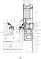
- Fig. 1 shows a first embodiment of a drainage system according to the invention, shown for the application of a door system with a door profile 1, which has a drop-down seal 2 on its underside and an externally arranged rain drainage profile 3.
- a threshold profile 4 can be seen, which in the illustrated and thus preferred embodiment is almost flush with an interior floor covering 5.
- the other structural elements shown such as foundation, insulation elements, screed, backfill tape, etc., are not provided with separate reference symbols, since these are present on site and have nothing to do directly with the drainage system according to the invention.
- a base profile 6 which is connected to the base profile 4 and rests on a support profile 8 carried by a support angle 7.
- the support profile 8 has unspecified mounting rails in its upper area, which serve to attach an inner and an outer film 9 as a moisture barrier to the support profile 8 with corresponding fastening clips.
- the actual drainage system initially and essentially comprises a drainage channel 11, which in cross-section has a connecting or covering profile 12 at its end facing away from the threshold and thus enables a stable and orderly transition to the adjacent paving P.
- a drain which initially consists of a screw socket 13, which is screwed into a socket 14, which in turn is screwed into a Angle pipe 15 is located which ends in a drain pipe 16 which leads into an underground drainage system (not shown).
- the actual connection between the base profile 6 and the drainage channel 11 is described in more detail below. It can also be seen that the drainage channel 11 is supported on the base profile 6 on the building side and is provided with a height-adjustable support foot 17 on the other side. A drainage grate 18 covers the drainage channel 11 at the top. A film 19 also ensures reliable drainage of all water, which can be pulled up on the external insulation to the base profile 6 and held there with a fastening clip 20 before the drainage channel 11 is hung in place.
- Fig. 2 describes a similar situation as in Fig. 1 , however, no door system is shown, but rather a version of a floor-to-ceiling window. Firstly, you can see a window profile 1' which is supported by a seal on a stop 2' of a threshold profile 4'. Here too, a rainwater drainage profile 3' ensures that the rainwater running down the window is directed into the drainage system.
- the threshold element 4' is firmly connected to the base profile 6 underneath via screwed or attached additional profiles (not specified in more detail). Due to the other reference symbols, reference is made to the - identical - description of Fig. 1 referred to.
- Fig. 3 shows a drainage system with a sliding system, which is not part of the invention.
- the profile 1" of the sliding element can be seen, which can be moved by means of a roller 2" on an unspecified rail of a threshold profile 4".
- the sliding element is located further inside the building and the threshold element 4" is correspondingly wider.
- a cover plate 3" ensures that the surface water is fed into the actual drainage channel 11.
- the threshold element 4" rests on two insulation elements 8' resting on the foundation and a support angle 7'. As in the previous embodiments, the edge of the inner and outer foils 9 is pulled up to the threshold element 4".
- the threshold element 4" is connected to a base element 6' underneath, which has a slightly different structure but the same function as the base profiles 6 already described in the Fig. 1 and 2 If water should enter the area directly below the cover plate, it will be drained through the horizontally permeable threshold profile 4" and over the base element 6' along the unspecified arrow in Fig. 3 also led into the drainage channel 11.
- the drainage channel 11 is identical to the drainage channels 11 already described. However, because the drainage channel 11 is installed deeper in this embodiment, the connection and cover profile 12' shown is also designed to be correspondingly higher, but fulfils the same function in relation to the paving P as already described. Fig. 1 described. The purpose of this deeper drainage channel (11) is to provide the possibility of draining the sliding element or a door or window element in a concealed manner.
- the further structure below the drainage channel 11 with the drainage elements 13, 14, 15 and 16 as well as the support foot 17 is again identical to the embodiments already described.
- a different, higher drainage grate 18' is also used, the cross-section of which is adapted to the geometric conditions.
- the film 19 is again attached to a corresponding holder of the base profile 6' using fastening clips 20.
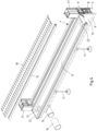
- Fig. 4 now a drainage system according to Fig. 1 shown in perspective. Firstly, one can see the threshold profile 4 and the drainage channel 11 attached to it, as well as the base profile 6 and the support profile 8. The two films 9 and the film 19 are only indicated by dash-dot lines.
- the threshold profile 4 is laterally limited by two vertically arranged frame profiles 21. End caps 22 close the open ends of the drainage channel 11 so that the water collecting therein can drain through the drain connection 13 and pipes 15 and 16, as already described. Furthermore, Fig. 4 The two support feet 17 used in this embodiment, the plug-on connection or cover profile 12 and the drainage grate 18 can also be seen.
- Fig. 5 now shows a short section of a drainage channel 11 according to the invention with an unspecified hole in the bottom for receiving the screw socket 13, which can be screwed into the end socket 14 and is sealed by means of a seal 14*. Furthermore, the individually shown end cap 22 can be seen, which is provided with three unspecified holes for receiving screws 23.
- Fig. 6 now shows the individual elements in cross-section in the not yet assembled state.
- the Fig. 6 The drainage channel 11 shown individually has, in the illustrated and thus preferred embodiment, a clamping web 24 for the positive and non-positive connection to the base profile 6. On the side facing away from the base profile 6, one can see a further clamping web 24' projecting upwards, which is connected to the connection or cover profile 12 arranged at a distance above it.
- the receiving channel 26 for receiving the support feet 17 can also be seen.
- the drainage channel 11 On the side facing the base profile 6, the drainage channel 11 also has a web 27 for transferring the load to the base profile 6.
- connection or cover profile 12 has a receptacle 28 on its underside, which corresponds to the clamping web 24' and creates a clean transition of the drainage system to the paving (not shown here).
- the base profile 6 is designed to be thermally separated to avoid a cold bridge and has, on its side facing the drainage channel 11, a receiving channel 29 for receiving the clamping web 24 of the drainage channel 11. Corresponding to the web 27 of the drainage channel 11, the base profile 6 has a shoulder 30 for supporting and thus for load transfer.
- a further receiving channel 31 serves, as already mentioned, Fig. 1 described for fastening the upper edge of a film (not shown) by means of fastening clips (also not shown).
- Fig. 7 now shows all elements from Fig. 6 and the already described foil 19 together with the fastening clip 20 in the fully assembled state. It is clearly visible that this is the same situation as in Fig. 1 and Fig. 2 is described.
- the reference symbols for the clamping bars 24' and 25' of the drainage channel 11 and the corresponding receptacles 28 and 29 have been omitted for reasons of clarity.
- the receptacle for fastening the film 19 by means of fastening clips 20 is also located in the "dry area" in the base element 6', since the projecting receptacle 29 for the clamping web 35 of the drainage channel 11 forms a water drip edge.
- connection or cover profile 12' forms a reliable hold for the adjacent leg of the attached drainage grate 18'.
Landscapes
- Engineering & Computer Science (AREA)
- Civil Engineering (AREA)
- Structural Engineering (AREA)
- Specific Sealing Or Ventilating Devices For Doors And Windows (AREA)
Description
- Die Erfindung betrifft ein Drainagesystem zum Abführen von Oberflächenwasser im Schwellenbereich von Tür- oder Fensterelementen mit einer Drainagerinne und wenigstens einem an eine erdgebundene Entwässerung anschließbaren Abfluss.
- Lineare Flächenentwässerungssysteme sind in vielerlei Ausführungen aus der Praxis bekannt. Sie sind besonders dann äußerst wichtig, wenn größere ebene Flächen ohne (oder mit zu geringer) Neigung das sich bei Regen sammelnde Oberflächenwasser in Richtung der Schwelle von Tür- oder Fensterelementen leiten.
- Wenn im Folgenden von Tür- oder Fensterelementen die Rede ist, so sollen davon auch entsprechende Tür- oder Fenster-Schiebeanlagen umfasst sein.
- Zum Schutz vor dem Eindringen von Wasser ins Gebäude wurden in der Vergangenheit meist entsprechend hohe Schwellen oder Stufen bei 'gefährdeten' Situationen von Tür- oder Fensterelementen realisiert. Häufig wurde dann allerdings vor diesen mechanischen Sperren kein Drainagesystem eingesetzt, was bei extremen Wetterstationen zu eindringendem Regenwasser und Gebäudeschäden führen kann.
- Werden zusätzlich eingelassene Drainagerinnen verlegt, wird das in der Drainagerinne gesammelte Wasser dann über einen entweder an der Unterseite oder seitlich angeordneten Abfluss einer erdgebundenen Entwässerung zugeführt.
- Die
DE 20 2013 003 423 U1 offenbart ein Drainagesystem mit einer Bodenschwelle für barrierefreie Übergänge. Die Bodenschwelle besteht dabei aus den Abschlusskörpern und dem dazwischen angeordneten Trägerkörper. Diese drei Elemente bilden zusammen mit den Magnetstreifen die gesamte Oberfläche der Bodenschwelle des Tür- bzw. Fensterelements. - In der
EP 2 362 057 A2 ist ein Drainagesystem beschrieben, welches ein Schwellenprofil in Form des sill profile umfasst. Dieses Schwellenprofil setzt sich aus dem interior profile und dem exterior profile zusammen. An das Schwellenprofil angeschlossen ist eine Drainagerinne in Form des channel profile. - Die
DE 299 05 191 U1 betrifft ein Sockelanschlusselement, welches an Gebäudewänden - mitunter mit einem inFig. 3 dargestellten Tür- bzw. Fensterelement - befestigt wird und einen dauerhaften Sockelanschluss und Drainageabschluss bildet. - In der
JP H10 102 558 A - In der
DE 197 44 242 A1 wird ein Aufsatz für eine Türschwelle offenbart, der aufgrund seiner Höhe das Eintreten von Wasser verhindert. - Heute sind Nullbarriere oder Universal Design Schlagworte, die bei der Planung und Umsetzung von öffentlichen und nicht öffentlichen Bauvorhaben im Entwurfsprozess immer wieder hervorgehoben werden. Sie verlangen, dass die Benutzung von Produkten einfach und flexibel für Menschen mit den unterschiedlichsten Fähigkeiten, sowohl von erfahrenen als auch von unerfahrenen Nutzern, ausgeführt werden können.
- Bei der Planung und Umsetzung öffentlicher und privater Bauvorhaben gibt es immer häufiger den (gesetzlichen) Anspruch an den barrierefreien Zugang. Mit der Einführung der Bauproduktenverordnung (EU 305/2011) wurden auch neue Grundanforderungen an Bauwerke gestellt. Hierzu zählt auch die Barrierefreiheit, diese wurde sowohl in der DIN 18040-1, für öffentliche Bereiche, als auch in der DIN 18040-2, für barrierefreies Wohnen, berücksichtigt. Die Normen fordern eine stufenlose Ausführung der Schwellenlösung von Zugängen, nur in Ausnahmefällen ist, sofern nicht anders realisierbar, eine maximale Bauhöhe von 20 mm zulässig. Im Widerspruch hierzu fordert die DIN 18195-5 eine Anschlusshöhe von 150 mm bei bodenbündigen (beispielsweise barrierefreien) Tür-/Fensterelementen.
- Um diesen Widerspruch aufzulösen, sehen die Richtlinien der ,RAL-Montage' gemäß RAL-Güteverband als flankierende bauliche Maßnahme den Einsatz von Entwässerungsrinnen (Drainagen) vor. Hierbei besteht allerdings das Problem, dass zwei unterschiedliche Gewerke, nämlich Tür- und Fenstermontage einerseits sowie Pflasterarbeiten andererseits, aufeinander abgestimmt werden müssen. Häufig wird hierbei entweder das Entwässerungssystem so positioniert, dass eine effektive Flächenentwässerung unmittelbar vor der Tür bzw. vor dem Fenster nicht gewährleistet ist oder es wird schon während der Planung nicht hinreichend berücksichtigt.
- Davon ausgehend liegt der vorliegenden Erfindung die Aufgabe zugrunde, das eingangs genannte und zuvor näher beschriebene Drainagesystem so auszugestalten, dass Schwelle und Drainagerinne derart aufeinander abgestimmt sind, dass sich beide Elemente miteinander verbinden lassen und dass es auch für alle Arten von barrierefreien Schwellensituationen einsetzbar ist.
- Die Aufgabe wird dadurch gelöst, das dass Drainagesystem gemäß Anspruch 1 eine Drainagerinne, ein Schwellenprofil und ein Basisprofil aufweist und wobei das Basisprofil
- unterhalb des Schwellenprofis des Tür- oder Fensterelements angeordnet ist, eine Stützfläche zur Lastabtragung der Drainagerinne aufweist und thermisch getrennt ausgeführt ist,
- mit dem Schwellenprofil verbindbar ist,
- mit der Drainagerinne verbindbar ist,
- sich in seiner Länge im Wesentlichen entlang der Breite des Tür- oder Fensterelements erstreckt,
- und die Drainagerinne jeweils über ihre gesamte Länge verlaufende Verbindungselemente zur form- und/oder kraftschlüssigen Verbindung untereinander aufweisen und
- eine, vorzugsweise federnd ausgeführte, Aufnahme für einen korrespondierenden Klemmsteg der Drainagerinne aufweist.
- Das erfindungsgemäße Schwellen- und Drainagesystem ermöglicht eine optimale Anpassung und integriert die Drainagerinne im direkten Anschluss an den Schwellenbereich der Tür, dem Fenster oder der Schiebeanlage. Das dazu eingesetzte Basisprofil wurde durch ein thermisch getrenntes Basisprofil realisiert und ist so gestaltet, dass es sowohl den unteren Abdichtungspunkt der Tür oder des Fensters aufnimmt, gleichzeitig aber auch den direkten Anschluss der linearen Flächenentwässerungsrinne ermöglicht.
- Erfindungsgemäß weisen das Basisprofil und die Drainagerinne jeweils über ihre gesamte Länge verlaufende Verbindungselemente zur form und/oder kraftschlüssigen Verbindung untereinander auf. Dadurch wird einerseits eine gute Abdichtung und andererseits eine hohe mechanische Festigkeit erreicht. Dazu weist das Basisprofil eine, vorzugsweise federnd ausgeführte, Aufnahme für einen korrespondierenden Klemmsteg auf. Im Rahmen der Erfindung ist natürlich auch eine Ausführung mit Klemmsteg am Basisprofil und korrespondierender Aufnahme in der Drainagerinne denkbar.
- Es ist vorgesehen, dass das Basisprofil eine Stützfläche zur Lastabtragung der Drainagerinne aufweist. Dies ist besonders während der Errichtung der Außenfläche nach Montage der Drainagerinne von Vorteil, da auf diese Weise die Drainagerinne schon von Anfang an belastbar, voll funktionsfähig und auch betretbar ist. Auch wenn die endgültige Pflasterung noch nicht abgeschlossen sein sollte.
- Nach einer weiteren Lehre der Erfindung weist das Basisprofil eine Aufnahme zur Befestigung einer Folie auf, die die Bauwerksabdichtung zum Anschluss gewährleistet. Dadurch kann eine unter der späteren Pflasterung verlegte wasserundurchlässige Folie, beispielsweise eine PVC-Folie, mit dem Basisprofil verbunden werden, bevor die Drainagerinne eingesetzt wird. Bevorzugt ist die Folie mittels Befestigungsclips in der Aufnahme des Basisprofils anschlagbar. Zweckmäßiger Weise verläuft die Folie dann entlang der Stützfläche des Basisprofils und wird von der Drainagerinne auf das Basisprofil gepresst.
- Eine andere bevorzugte Ausbildung der Erfindung sieht vor, dass das Basisprofil Kupplungsmöglichkeiten zur Verbindung mit weiteren Profilen, Stegen oder dergleichen aufweist. Auf diese Weise kann das erfindungsgemäße Drainagesystem auch an bereits bestehenden Schwellenprofilen befestigt und somit zur Nachrüstung eingesetzt werden.
- Bevorzugt sind ferner das Basisprofil und die Drainagerinne als Aluminiumprofile ausgeführt. Dies ermöglicht eine einfache Herstellung, hohe Stabilität und Lebensdauer.
- Die eigentliche Drainagerinne ist flexibel auf die gewünschte Länge, Elementbreite oder Laibung der jeweiligen Schwellensituation anpassbar. Insbesondere kann eine optimale Anpassung ihrer Länge an das vorhandene Basisprofil durch entsprechendes Kürzen vor Ort auf der Baustelle erfolgen. Durch entsprechende Endkappen wird diese dann dauerhaft verschlossen. Dazu weist die Drainagerinne eine Mehrzahl von Schraubkanälen zur Aufnahme von Verschraubungen mit den an den offenen Enden der Drainagerinne anschraubbaren Endkappen auf.
- Die Montage erfolgt einfach mit der bewährten 'Klipstechnik', einer Verrastung, die weiter unten noch näher beschrieben werden wird. Wichtig war bei der Entwicklung besonders der universale Einsatz sowohl für die Renovierung als auch im Neubau. Mit einer minimalen Einbauhöhe von 46 mm und einer punktuellen Ablaufhöhe von 140 mm ist das erfindungsgemäße Drainagesystem überall einsetzbar. Die Entwässerung der Rinne mit einer Ablaufleistung von ca. 200 l/min. kann über einen Standard DN 50 Anschluss erfolgen, dieser kann frei in der Rinne positioniert und je nach Erfordernis auch mehrfach gesetzt werden. Der DN Standard gewährleistet eine definierte Schnittstelle zu erdgebundenen Entwässerungssystemen.
- Eine weitere Lehre der Erfindung sieht vor, dass die Drainagerinne im Bereich ihrer schwellenabgewandten Seitenkante einen Klemmsteg oder eine Aufnahme zum Verbinden mit einem Anschluss- oder Abdeckprofil aufweist. Ein entsprechendes Anschluss- oder Abdeckprofil sieht daher eine korrespondierende Aufnahme oder einen Klemmsteg zur Verbindung mit der Drainagerinne vor. Hierdurch wird ein besonders eleganter Übergang zur benachbarten Pflasteroberfläche erreicht.
- In weiterer bevorzugter Ausbildung der Erfindung weist die Drainagerinne einen Steg zur Lastabtragung auf das Basisprofil auf, welches dazu über eine korrespondierende Stützfläche verfügt. In Verbindung mit der bevorzugten Klemmverbindung wird daher eine stabile Einheit beider Konstruktionselemente geschaffen.
- Nach einer weiteren Lehre der Erfindung weist die Drainagerinne eine Mehrzahl von Schraubkanälen zur Aufnahme von Verschraubungen mit an den offenen Enden der Drainagerinne ansetzbaren Endkappen auf. Durch die feste Verschraubung wird zuverlässig garantiert, dass seitlich kein Wasser aus der Drainagerinne austreten kann.
- In weiterer Ausgestaltung der Erfindung weist die Drainagerinne an ihrer Unterseite wenigstens einen Aufnahmekanal für Stützfüße auf. Durch die bevorzugt höhenverstellbar ausgeführten Stützfüße können punktuelle Lasten bis zu 1,5 t aufgenommen werden. Die Stützfüße sind ferner frei über die Länge der Drainagerinne positionierbar sind.
- Schließlich wird das erfindungsgemäße Drainagesystem mit einem Drainagerost abgedeckt. Dazu können hochwertige streusalzbeständige Edelstahlroste zum Einsatz kommen.
- Das erfindungsgemäße Drainagesystem wird nachfolgend anhand einer lediglich bevorzugte Ausführungsbeispiele darstellenden Zeichnung näher erläutert. In der Zeichnung zeigen
- Fig. 1
- ein erstes Ausführungsbeispiel eines erfindungsgemäßen Drainagesystems für ein Türelement im Vertikalschnitt,
- Fig. 2
- ein zweites Ausführungsbeispiel eines erfindungsgemäßen Drainagesystems für ein Fensterelement im Vertikalschnitt,
- Fig.3
- ein Drainagesystems für ein Schiebeelement im Vertikalschnitt, welches nicht zur Erfindung gehört,
- Fig. 4
- das erfindungsgemäße Drainagesystem aus
Fig. 1 in perspektivischer Ansicht, - Fig. 5
- den Aufbau einer Drainagerinne des erfindungsgemäßen Drainagesystems in perspektivischer Ansicht,
- Fig. 6
- die einzelnen Elemente des erfindungsgemäßen Drainagesystems gemäß den
Figuren 1 oder2 im Querschnitt, - Fig. 7
- die Elemente aus
Fig. 6 , fertig montiert im Querschnitt und - Fig. 8
- die einzelnen Elemente des Drainagesystems aus
Fig. 3 , fertig moniert im Querschnitt. -
Fig. 1 zeigt zunächst ein erstes Ausführungsbeispiel eines erfindungsgemäßen Drainagesystems, dargestellt für den Anwendungsfall einer Türanlage mit einem Türprofil 1, welches an seiner Unterseite eine Absenkdichtung 2 und ein außen angeordnetes Regenablaufprofil 3 aufweist. - Unterhalb des Türprofils 1 erkennt man ein Schwellenprofil 4, welches im dargestellten und insoweit bevorzugten Ausführungsbeispiel nahezu bündig mit einem im inneren befindlichen Bodenbelag 5 fluchtet. Zur Verbesserung der Übersichtlichkeit sind die weiteren baulichen gezeigten Elemente wie Fundament, Dämmelemente, Estrich, Hinterfüllband etc. nicht mit separaten Bezugszeichen versehen, da diese bauseits vorhanden sind und mit dem erfindungsgemäßen Drainagesystem unmittelbar nichts zu tun haben.
- Unterhalb des Schwellenprofils 4 erkennt man, das wesentliche Element des erfindungsgemäßen Drainagesystems, nämlich ein Basisprofil 6, welches mit dem Sockelprofil 4 verbunden ist und sich auf einem von einem Tragwinkel 7 getragenen Tragprofil 8 abstützt.
- Man erkennt ferner, dass das Tragprofil 8 in seinem oberen Bereich nicht näher bezeichnete Aufnahmeschienen aufweist, welche dazu dienen, eine innere und eine äußere Folie 9 als Feuchtesperre mit entsprechenden Befestigungsclips am Tragprofil 8 zu befestigen.
- Das eigentliche Drainagesystem weist zunächst und im Wesentlichen eine Drainagerinne 11 auf, welche im Querschnitt an ihrem schwellenabgewandten Ende ein Anschluss- bzw. Abdeckprofil 12 aufweist und so einen stabilen und ordentlichen Übergang zur benachbarten Pflasterung P ermöglicht.
- Zur besseren Erläuterung des Abtransportes von Oberflächenwasser wurde der Schnitt durch einen Abfluss gelegt, welcher zunächst aus einem Schraubstutzen 13 besteht, der in einen Stutzen 14 eingeschraubt ist, welcher wiederum in einem Winkelrohr 15 sitzt welches in einem Abflussrohr 16 mündet, welches in ein erdgebundenes Entwässerungssystem (nicht dargestellt) führt.
- Die eigentliche Verbindung zwischen Basisprofil 6 und Drainagerinne 11 wird weiter unten näher beschrieben. Man erkennt ferner, dass sich die Drainagerinne 11 gebäudeseitig auf dem Basisprofil 6 abstützt und auf seiner anderen Seite mit einem höhenverstellbaren Stützfuß 17 versehen ist. Ein Drainagerost 18 deckt die Drainagerinne 11 nach oben ab. Für eine zuverlässige Ableitung sämtlichen Wassers sorgt ferner eine Folie 19, welche an der Außendämmung bis zum Basisprofil 6 hochgezogen und dort mit einem Befestigungsclip 20 gehalten werden kann, bevor die Drainagerinne 11 eingehängt wird.
-
Fig. 2 beschreibt eine ähnliche Situation wie inFig. 1 , wobei jedoch keine Türanlage, sondern eine Ausführung eines bodentiefen Fensters gezeigt ist. Man erkennt zunächst ein Fensterprofil 1' welches sich mit einer Dichtung an einem Anschlag 2' eines Schwellenprofils 4' abstützt. Auch hier sorgt ein Regenablaufprofil 3' dafür, dass das am Fenster herablaufende Regenwasser in die Drainage geleitet wird. - Das Schwellenelement 4' ist über aufgeschraubte bzw. aufgesteckte nicht näher bezeichnete Zusatzprofile mit dem darunter befindlichen Basisprofil 6 fest verbunden. Wegen der weiteren Bezugszeichen wird auf die - identische - Beschreibung von
Fig. 1 verwiesen. -
Fig. 3 zeigt ein Drainagesystem mit einer Schiebeanlage, welches nicht zur Erfindung gehört. Man erkennt zunächst das Profil 1" des Schiebeelements, welches sich mittels einer Rolle 2" auf einer nicht näher bezeichneten Schiene eines Schwellenprofiles 4" verfahren lässt. Bei dieser Einbausituation befindet sich das Schiebelement weiter innen im Gebäude und ist das Schwellenelement 4" entsprechend breiter ausgebildet. Ein Abdeckblech 3" sorgt dabei für die Zuleitung des Oberflächenwassers in die eigentliche Drainagerinne 11. - Bei diesem Ausführungsbeispiel lastet das Schwellenelement 4" auf zwei auf dem Fundament und einem Tragwinkel 7' aufliegenden Dämmelementen 8'. Wie bei den vorherigen Ausführungsbeispielen ist der Rand der inneren und äußeren Folien 9 bis zum Schwellenelement 4" hochgezogen.
- An seinem in
Fig. 3 linken Ende ist das Schwellenelement 4" mit einem darunter liegenden Basiselement 6' verbunden, welches einen etwas anderen Aufbau, jedoch die gleiche Funktion hat wie die bereits beschriebenen Basisprofile 6 in denFig. 1 und2 . Falls Wasser in den direkten Bereich unterhalb des Abdeckbleches gelangen sollte, so wird dieses durch das horizontal entsprechend durchlässig ausgeführte Schwellenprofil 4" und über das Basiselement 6' entlang des nicht näher bezeichneten Pfeils inFig. 3 ebenfalls in die Drainagerinne 11 geleitet. - Die Drainagerinne 11 entspricht identisch wieder der bereits beschriebenen Drainagerinnen 11. Dadurch, dass bei diesem Ausführungsbeispiel die Drainagerinne 11 jedoch tiefer verbaut ist, ist auch das dargestellte Anschluss- und Abdeckprofil 12' entsprechend höher ausgebildet, erfüllt aber die gleiche Funktion gegenüber der Pflasterung P wie bereits zu
Fig. 1 beschrieben. Sinn dieser tieferligenden Drainagerinne (11) ist die Möglichkeit, das Schiebeelement oder auch ein Tür- oder Fensterelement verdeckt zu entwässern. Der weitere Aufbau unterhalb der Drainagerinne 11 mit dem den Abflusselementen 13, 14, 15 und 16 sowie dem Stützfuß 17 ist wiederum identisch wie mit den bereits beschriebenen Ausführungsbeispielen. - Bedingt durch die tiefere Anordnung der Drainagerinne 11 wird bei
Fig. 3 jedoch auch ein anderer, höher bauender, Drainagerost 18' verwendet, dessen Querschnitt an die geometrischen Bedingungen angepasst ist. Wie zuvor beschrieben wird auch hier die Folie 19 wieder mit Hilfe von Befestigungsclips 20 an einer entsprechenden Aufnahme des Basisprofils 6' befestigt. - Zur besseren Erläuterung ist in
Fig. 4 nun ein Drainagesystem gemäßFig. 1 perspektivisch dargestellt. Man erkennt zunächst das Schwellenprofil 4 und die daran angesetzte Drainagerinne 11, sowie das Basisprofil 6 und das Tragprofil 8. Die beiden Folien 9 und die Folie 19 sind lediglich strichpunktiert angedeutet. - Das Schwellenprofil 4 wird seitlich von zwei vertikal angeordneten Rahmenprofilen 21 begrenzt. Endkappen 22 verschließen die offenen Enden der Drainagerinne 11, so dass das darin sammelnde Wasser, wie bereits beschrieben, durch den Abflussstutzen 13 und Rohre 15 und 16 ablaufen kann. Ferner sind in
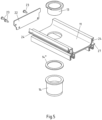
Fig. 4 noch die in diesem Ausführungsbeispiel verwendeten beiden Stützfüße 17, das aufzusteckende Anschluss- bzw. Abdeckprofil 12 und der Drainagerost 18 zu erkennen.Fig. 5 zeigt nun einen kurzen Abschnitt einer erfindungsgemäßen Drainagerinne 11 mit einer nicht näher bezeichneten Bohrung im Boden zur Aufnahme des Schraubstutzens 13, welcher in den Abschlussstutzen 14 einschraubbar ist und mittels einer Dichtung 14* abgedichtet wird. Ferner erkennt man die einzeln dargestellte Endkappe 22, welche mit drei nicht näher bezeichneten Bohrungen zur Aufnahme von Schrauben 23 versehen ist. -
Fig. 6 zeigt nun die einzelnen Elemente im Querschnitt im noch nicht montierten Zustand. Die inFig. 6 einzeln dargestellte Drainagerinne 11 verfügt im dargestellten und insoweit bevorzugten Ausführungsbeispiel über einen Klemmsteg 24 zur form- und kraftschlüssigen Verbindung mit dem Basisprofil 6. Auf der dem Basisprofil 6 abgewandten Seite erkennt man einen nach oben ragenden weiteren Klemmsteg 24', welcher mit dem darüber beabstandet angeordneten Anschluss- bzw. Abdeckprofil 12 verbunden wird. - Man erkennt ferner deutlich drei Schraubkanäle 25 in der Drainagerinne 11. Ferner ist der Aufnahmekanal 26 zur Aufnahme der Stützfüße 17 zu erkennen. Auf der dem Basisprofil 6 zugewandten Seite verfügt die Drainagerinne 11 darüber hinaus über einen Steg 27 zur Lastabtragung auf das Basisprofil 6.
- Das Anschluss- bzw. Abdeckprofil 12 weist auf seiner Unterseite eine Aufnahme 28 auf, welche mit dem Klemmsteg 24' korrespondiert und einen sauberen Übergang des Drainagesystems zur (hier nicht dargestellten) Pflasterung herstellt.
- Das Basisprofil 6 ist zur Vermeidung einer Kältebrücke erkennbar thermisch getrennt ausgebildet und weist auf seiner der Drainagerinne 11 zugewandten Seite zunächst einen Aufnahmekanal 29 zur Aufnahme des Klemmstegs 24 der Drainagerinne 11 auf. Korrespondierend zum Steg 27 der Drainagerinne 11 weist das Basisprofil 6 eine Schulter 30 zum Abstützen und damit zur Lastabtragung auf. Ein weiterer Aufnahmekanal 31 dient, wie bereits zur
Fig. 1 beschrieben, zur Befestigung des oberen Randes einer Folie (nicht dargestellt) mittels (ebenfalls nicht dargestellter) Befestigungsclips. -
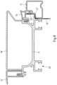
Fig. 7 zeigt nun sämtliche Elemente ausFig. 6 sowie die bereits beschriebene Folie 19 nebst Befestigungsclip 20 in fertig montiertem Zustand. Man erkennt deutlich, dass es sich um dieselbe Situation handelt, wie sie auch inFig. 1 undFig. 2 beschrieben ist. Auf die Bezugszeichen der Klemmstege 24' und 25' der Drainagerinne 11 und die entsprechenden Aufnahmen 28 und 29 wurde aus Gründen der besseren Übersichtlichkeit verzichtet. Durch das Verrasten von Drainagerinne 11 und Basisprofil 6 entsteht eine stabile und optisch ansprechende Konstruktion, wobei gleichzeitig die Folie 19 zwischen den beiden Elementen verspannt wird, so dass eine zuverlässige Ableitung jeglichen Oberflächenwassers von der Gebäudewand garantiert ist. - Schließlich ist in
Fig. 8 noch das Drainagesystem ausFig. 3 in fertig montiertem Zustand im Querschnitt dargestellt. Auch hier erfolgt die Verrastung ('Klipsen') und Abstützung zwischen Drainagerinne 11 und Basisprofil 6' wie zuvor beschrieben. Eine geneigte Stegfläche 32 sorgt dafür, dass etwaiges im hier nicht dargestellten Schwellenprofil befindliches Wasser direkt in die Drainagerinne 11 ablaufen kann (vgl. auch den Pfeil inFig. 3 ). - Wie auch bereits beim Basiselement 6 gezeigt, liegt die Aufnahme zur Befestigung der Folie 19 mittels Befestigungsclips 20 auch beim Basiselement 6' im "trockenen Bereich", da die vorspringende Aufnahme 29 für den Klemmsteg 35 der Drainagerinne 11 eine Wasserabtropfkante bildet.
- Das "verlängerte" Anschluss- bzw. Abdeckprofil 12' bildet dabei einen zuverlässigen Halt für den benachbarten Schenkel des aufgesetzten Drainagerosts 18'.
- Alle Figuren, mit Ausnahme der
Figuren 3 und8 , stellen nur bevorzugte Ausführungsbeispiele des erfindungsgemäßen Drainagesystems dar und sollen deutlich machen, dass dieses System im Rahmen aller Patentansprüche beliebig variiert werden kann, solange nur die Wechselwirkung zwischen Drainagerinne und Basisprofil und damit die gewünschten Eigenschaften hinsichtlich Form und Funktion des erfindungsgemäßen Drainagesystems erfüllt bleiben.
Claims (14)
- Drainagesystem zum Abführen von Oberflächenwasser im Schwellenbereich von Tür- oder Fensterelementen mit einer Drainagerinne (11) und wenigstens einem an eine erdgebundene Entwässerung anschließbaren Abfluss, wobei das Drainagesystem die Drainagerinne, ein Schwellenprofil (4, 4', 4") und ein Basisprofil (6, 6') aufweist, wobei das Basisprofil (6, 6'):- mit dem Schwellenprofil (4, 4', 4") verbindbar ist, und- mit der Drainagerinne (11) verbindbar ist,dadurch gekennzeichnet, dass
das Basisprofil (6, 6'):- unterhalb des Schwellenprofis (4, 4', 4") des Tür- oder Fensterelements (1, 1', 1") angeordnet ist, eine Stützfläche (30) zur Lastabtragung der Drainagerinne (11) aufweist und thermisch getrennt ausgeführt ist.- und die Drainagerinne (11) jeweils über ihre gesamte Länge verlaufende Verbindungselemente (29, 24) zur form- und/oder kraftschlüssigen Verbindung untereinander aufweisen und- eine, vorzugsweise federnd ausgeführte, Aufnahme (29) für einen korrespondierenden Klemmsteg (24) der Drainagerinne (11) aufweist. - Drainagesystem nach Anspruch 1,
dadurch gekennzeichnet, dass das Basisprofil (6, 6') eine Aufnahme (31) zur Befestigung einer Folie (19) aufweist. - Drainagesystem nach Anspruch 2,
dadurch gekennzeichnet, dass
die Folie (19) mittels Befestigungsclips (20) in der Aufnahme (31) des Basisprofils (6, 6') anschlagbar ist. - Drainagesystem nach einem der Ansprüche 1 bis 3,
dadurch gekennzeichnet, dass
das Basisprofil (6, 6') Kupplungsmöglichkeiten zur Verbindung mit weiteren Profilen, Stegen oder dergleichen aufweist. - Drainagesystem nach einem der Ansprüche 1 bis 4,
dadurch gekennzeichnet, dass
das Basisprofil (6, 6') und die Drainagerinne (11) als Aluminiumprofile ausgeführt sind. - Drainagesystem nach Anspruch 5,
dadurch gekennzeichnet, dass
die Drainagerinne (11) eine Mehrzahl von Schraubkanälen (25) zur Aufnahme von Verschraubungen (23) mit an den offenen Enden der Drainagerinne (11) ansetzbaren Endkappen (22) aufweist. - Drainagesystem nach Anspruch 5 oder 6,
dadurch gekennzeichnet, dass
die Drainagerinne (11) an ihrer Unterseite wenigstens einen Aufnahmekanal (26) für Stützfüße (17) aufweist. - Drainagesystem nach Anspruch 7,
dadurch gekennzeichnet, dass
die Stützfüße (17) höhenverstellbar ausgeführt sind. - Drainagesystem nach Anspruch 7 oder 8,
dadurch gekennzeichnet, dass
die Stützfüße (17) frei über die Länge der Drainagerinne (11) positionierbar sind. - Drainagesystem nach einem der Ansprüche 1 bis 9,
dadurch gekennzeichnet, dass
die Drainagerinne (11) im Bereich ihrer schwellenabgewandten Seitenkante einen Klemmsteg (24') oder eine Aufnahme zum Verbinden mit einem Anschluss- oder Abdeckprofil (12) aufweist. - Drainagesystem nach Anspruch 10,
dadurch gekennzeichnet, dass
das Anschluss- oder Abdeckprofil (12) eine Aufnahme (28) oder einen Klemmsteg zur Verbindung mit der Drainagerinne (11) aufweist. - Drainagesystem nach einem der Ansprüche 1 bis 11,
dadurch gekennzeichnet, dass
die Drainagerinne (11) einen Steg (27) zur Lastabtragung auf das Basisprofil (6, 6') aufweist, welches dazu über eine korrespondierende Stützfläche (30) verfügt. - Drainagesystem nach einem der Ansprüche 1 bis 12,
dadurch gekennzeichnet, dass
die Drainagerinne (11) in ihrem unteren Bereich zur Aufnahme eines Abflusses eben ausgeführt ist. - Drainagesystem nach einem der Ansprüche 1 bis 13,
dadurch gekennzeichnet, dass
die Drainagerinne (11) zur oberen Abdeckung mit einem Drainagerost (18,18`) versehen ist.
Priority Applications (1)
| Application Number | Priority Date | Filing Date | Title |
|---|---|---|---|
| PL15202343.8T PL3043017T5 (pl) | 2015-01-09 | 2015-12-23 | System drenażowy do elementów drzwi i okien |
Applications Claiming Priority (1)
| Application Number | Priority Date | Filing Date | Title |
|---|---|---|---|
| DE102015100266.3A DE102015100266A1 (de) | 2015-01-09 | 2015-01-09 | Drainagesystem für Tür- und Fensterelemente |
Publications (3)
| Publication Number | Publication Date |
|---|---|
| EP3043017A1 EP3043017A1 (de) | 2016-07-13 |
| EP3043017B1 EP3043017B1 (de) | 2018-11-14 |
| EP3043017B2 true EP3043017B2 (de) | 2024-10-23 |
Family
ID=55027457
Family Applications (1)
| Application Number | Title | Priority Date | Filing Date |
|---|---|---|---|
| EP15202343.8A Active EP3043017B2 (de) | 2015-01-09 | 2015-12-23 | Drainagesystem für tür- und fensterelemente |
Country Status (3)
| Country | Link |
|---|---|
| EP (1) | EP3043017B2 (de) |
| DE (1) | DE102015100266A1 (de) |
| PL (1) | PL3043017T5 (de) |
Families Citing this family (6)
| Publication number | Priority date | Publication date | Assignee | Title |
|---|---|---|---|---|
| CN106837123A (zh) * | 2017-04-03 | 2017-06-13 | 张祯翔 | 一种建筑门窗迂回排水孔盖 |
| DE202018100426U1 (de) * | 2018-01-25 | 2018-02-07 | Thomas Seidl | Lastabtragendes Ausgleichselement mit Wärmedämmung |
| DE102018112434A1 (de) * | 2018-05-24 | 2019-11-28 | SCHÜCO International KG | Fenster |
| DE102019116285A1 (de) * | 2019-06-14 | 2020-12-17 | Gest Holding Gmbh | Entwässerungsvorrichtung sowie Verdunkelungssystem aufweisend die Entwässerungsvorrichtung |
| DE202019106103U1 (de) | 2019-11-04 | 2019-11-25 | Hautau Gmbh | Drainageeinrichtung für Tür- oder Fensterelemente |
| AT524419B1 (de) * | 2021-08-06 | 2022-06-15 | Mueller Guenther | Formteil |
Citations (3)
| Publication number | Priority date | Publication date | Assignee | Title |
|---|---|---|---|---|
| DE202010004020U1 (de) † | 2010-03-22 | 2011-07-27 | Inge Frey | Bodenschwelle |
| DE202013003423U1 (de) † | 2013-04-12 | 2013-05-27 | Inge Frey | Bodenschwelle , insbesondere für barrierefreie Übergänge |
| WO2013113914A2 (de) † | 2012-02-03 | 2013-08-08 | Claudia Rager-Frey | Barrierefreie bodenschwelle, insbesondere altbau- bzw. renovierungsschwelle |
Family Cites Families (10)
| Publication number | Priority date | Publication date | Assignee | Title |
|---|---|---|---|---|
| DE4433145A1 (de) | 1994-09-17 | 1996-03-21 | Harry Frey | Magnetische Türdichtung |
| DE29507277U1 (de) | 1995-05-02 | 1995-07-20 | Frey, Harry, 87600 Kaufbeuren | Bodenschwelle für Türen |
| JP3234516B2 (ja) * | 1996-08-05 | 2001-12-04 | ワイケイケイアーキテクチュラルプロダクツ株式会社 | 排水溝ユニットおよびこれを用いた建物開口部の排水構造 |
| DE19744242A1 (de) * | 1997-10-07 | 1999-04-29 | Peter Willrich | Türschwellenvorrichtung mit einer Türschwelle |
| DE29905191U1 (de) * | 1999-03-22 | 2000-08-17 | Ruch, Herwig, Dipl.-Ing.-Architekt (FH), 73540 Heubach | Sockelanschlußelement |
| DE20106929U1 (de) | 2001-04-20 | 2002-08-29 | Frey, Inge, 87600 Kaufbeuren | Türdichtung |
| DE102009056118A1 (de) | 2009-11-30 | 2011-06-01 | Inge Frey | Dichtung, insbesondere für Schiebetüren |
| BE1019134A3 (nl) * | 2010-01-07 | 2012-03-06 | Reynaers Aluminium Nv | Afwateringssysteem voor een schuifraam of schuifdeur. |
| AT511798B1 (de) * | 2011-12-29 | 2013-03-15 | Ifn Holding Ag | Bodenschwelle für eine hebe/schiebetür |
| GB201318985D0 (en) | 2013-10-28 | 2013-12-11 | Kennedy Anne | A drainage unit |
-
2015
- 2015-01-09 DE DE102015100266.3A patent/DE102015100266A1/de active Pending
- 2015-12-23 EP EP15202343.8A patent/EP3043017B2/de active Active
- 2015-12-23 PL PL15202343.8T patent/PL3043017T5/pl unknown
Patent Citations (4)
| Publication number | Priority date | Publication date | Assignee | Title |
|---|---|---|---|---|
| DE202010004020U1 (de) † | 2010-03-22 | 2011-07-27 | Inge Frey | Bodenschwelle |
| WO2013113914A2 (de) † | 2012-02-03 | 2013-08-08 | Claudia Rager-Frey | Barrierefreie bodenschwelle, insbesondere altbau- bzw. renovierungsschwelle |
| DE202013003423U1 (de) † | 2013-04-12 | 2013-05-27 | Inge Frey | Bodenschwelle , insbesondere für barrierefreie Übergänge |
| WO2014167077A1 (de) † | 2013-04-12 | 2014-10-16 | Inge Frey | Bodenschwelle, insbesondere für barrierefreie uebergaenge |
Also Published As
| Publication number | Publication date |
|---|---|
| EP3043017A1 (de) | 2016-07-13 |
| DE102015100266A1 (de) | 2016-07-14 |
| PL3043017T3 (pl) | 2019-03-29 |
| PL3043017T5 (pl) | 2024-12-23 |
| EP3043017B1 (de) | 2018-11-14 |
Similar Documents
| Publication | Publication Date | Title |
|---|---|---|
| EP3043017B2 (de) | Drainagesystem für tür- und fensterelemente | |
| EP2957702B2 (de) | Türschwellensystem für eine haustür, eine ladentür oder dergleichen | |
| EP2202378B1 (de) | Nachtraeglich montierbare Bodenschwelle für ein Hebeschiebfenster und Montageverfahren | |
| DE2401307A1 (de) | Fensterkonstruktion | |
| EP2809864B1 (de) | Barrierefreie bodenschwelle, insbesondere altbau- bzw. renovierungsschwelle | |
| DE202013003423U1 (de) | Bodenschwelle , insbesondere für barrierefreie Übergänge | |
| DE202010016773U1 (de) | Stützhalter für wetterseitige Metallfensterbänke | |
| AT15735U1 (de) | Entwässerungssystem | |
| EP2947253A1 (de) | Fenster, insbesondere wohndachfenster, mit einer dämmung und mindestens einem abdeckblech | |
| EP3130739B2 (de) | Schwelle mit zusatzvorrichtung zur verringerung der barrierewirkung | |
| EP0725194A1 (de) | Entwässerungssytem für Balkone | |
| EP3783187A2 (de) | System mit einem fenster, einer verschattungsanlage und einem entwässerungselement | |
| DE19516464A1 (de) | Bausatz zur Halterung einer aus Platten, insbesondere Glasplatten oder dergleichen zusammensetzbaren Fassade oder Dacheindeckung | |
| DE102006007742A1 (de) | Bodenschwelle | |
| DE202012001082U1 (de) | Barrierefreie Bodenschwelle, insbesondere Altbau- bzw. Renovierungsschwelle | |
| DE10037880C1 (de) | Wärmegedämmte Schutzschiene für Fenster oder Türen | |
| EP3258049B1 (de) | Vorrichtung zum abdecken des äusseren bereichs der unteren begrenzung einer gebäudeöffnung | |
| DE202007002319U1 (de) | Schließteil | |
| EP1251234A1 (de) | Türdichtung | |
| AT12925U1 (de) | Zusatzelement zum Anordnen an einer Bodenschwelle | |
| DE8531254U1 (de) | Vorrichtung zum Verschließen einer vorzugsweise geneigten Dachöffnung | |
| EP3258048B1 (de) | Vorrichtung zum niederhalten eines abdeckblechs | |
| AT12155U1 (de) | Führungsschiene | |
| DE20001759U1 (de) | Tür mit in einem Rahmen angeordnetem Türeinsatz | |
| EP0958774A2 (de) | Duschabtrennung |
Legal Events
| Date | Code | Title | Description |
|---|---|---|---|
| PUAI | Public reference made under article 153(3) epc to a published international application that has entered the european phase |
Free format text: ORIGINAL CODE: 0009012 |
|
| AK | Designated contracting states |
Kind code of ref document: A1 Designated state(s): AL AT BE BG CH CY CZ DE DK EE ES FI FR GB GR HR HU IE IS IT LI LT LU LV MC MK MT NL NO PL PT RO RS SE SI SK SM TR |
|
| AX | Request for extension of the european patent |
Extension state: BA ME |
|
| STAA | Information on the status of an ep patent application or granted ep patent |
Free format text: STATUS: REQUEST FOR EXAMINATION WAS MADE |
|
| 17P | Request for examination filed |
Effective date: 20161221 |
|
| RBV | Designated contracting states (corrected) |
Designated state(s): AL AT BE BG CH CY CZ DE DK EE ES FI FR GB GR HR HU IE IS IT LI LT LU LV MC MK MT NL NO PL PT RO RS SE SI SK SM TR |
|
| STAA | Information on the status of an ep patent application or granted ep patent |
Free format text: STATUS: EXAMINATION IS IN PROGRESS |
|
| 17Q | First examination report despatched |
Effective date: 20170529 |
|
| GRAP | Despatch of communication of intention to grant a patent |
Free format text: ORIGINAL CODE: EPIDOSNIGR1 |
|
| STAA | Information on the status of an ep patent application or granted ep patent |
Free format text: STATUS: GRANT OF PATENT IS INTENDED |
|
| INTG | Intention to grant announced |
Effective date: 20180620 |
|
| GRAS | Grant fee paid |
Free format text: ORIGINAL CODE: EPIDOSNIGR3 |
|
| GRAA | (expected) grant |
Free format text: ORIGINAL CODE: 0009210 |
|
| STAA | Information on the status of an ep patent application or granted ep patent |
Free format text: STATUS: THE PATENT HAS BEEN GRANTED |
|
| AK | Designated contracting states |
Kind code of ref document: B1 Designated state(s): AL AT BE BG CH CY CZ DE DK EE ES FI FR GB GR HR HU IE IS IT LI LT LU LV MC MK MT NL NO PL PT RO RS SE SI SK SM TR |
|
| REG | Reference to a national code |
Ref country code: AT Ref legal event code: REF Ref document number: 1065025 Country of ref document: AT Kind code of ref document: T Effective date: 20181115 Ref country code: CH Ref legal event code: EP |
|
| REG | Reference to a national code |
Ref country code: CH Ref legal event code: NV Representative=s name: SCHMAUDER AND PARTNER AG PATENT- UND MARKENANW, CH |
|
| REG | Reference to a national code |
Ref country code: DE Ref legal event code: R096 Ref document number: 502015006853 Country of ref document: DE |
|
| REG | Reference to a national code |
Ref country code: IE Ref legal event code: FG4D Free format text: LANGUAGE OF EP DOCUMENT: GERMAN |
|
| REG | Reference to a national code |
Ref country code: NL Ref legal event code: FP |
|
| REG | Reference to a national code |
Ref country code: LT Ref legal event code: MG4D |
|
| PG25 | Lapsed in a contracting state [announced via postgrant information from national office to epo] |
Ref country code: LV Free format text: LAPSE BECAUSE OF FAILURE TO SUBMIT A TRANSLATION OF THE DESCRIPTION OR TO PAY THE FEE WITHIN THE PRESCRIBED TIME-LIMIT Effective date: 20181114 Ref country code: HR Free format text: LAPSE BECAUSE OF FAILURE TO SUBMIT A TRANSLATION OF THE DESCRIPTION OR TO PAY THE FEE WITHIN THE PRESCRIBED TIME-LIMIT Effective date: 20181114 Ref country code: LT Free format text: LAPSE BECAUSE OF FAILURE TO SUBMIT A TRANSLATION OF THE DESCRIPTION OR TO PAY THE FEE WITHIN THE PRESCRIBED TIME-LIMIT Effective date: 20181114 Ref country code: BG Free format text: LAPSE BECAUSE OF FAILURE TO SUBMIT A TRANSLATION OF THE DESCRIPTION OR TO PAY THE FEE WITHIN THE PRESCRIBED TIME-LIMIT Effective date: 20190214 Ref country code: IS Free format text: LAPSE BECAUSE OF FAILURE TO SUBMIT A TRANSLATION OF THE DESCRIPTION OR TO PAY THE FEE WITHIN THE PRESCRIBED TIME-LIMIT Effective date: 20190314 Ref country code: FI Free format text: LAPSE BECAUSE OF FAILURE TO SUBMIT A TRANSLATION OF THE DESCRIPTION OR TO PAY THE FEE WITHIN THE PRESCRIBED TIME-LIMIT Effective date: 20181114 Ref country code: NO Free format text: LAPSE BECAUSE OF FAILURE TO SUBMIT A TRANSLATION OF THE DESCRIPTION OR TO PAY THE FEE WITHIN THE PRESCRIBED TIME-LIMIT Effective date: 20190214 Ref country code: ES Free format text: LAPSE BECAUSE OF FAILURE TO SUBMIT A TRANSLATION OF THE DESCRIPTION OR TO PAY THE FEE WITHIN THE PRESCRIBED TIME-LIMIT Effective date: 20181114 |
|
| PG25 | Lapsed in a contracting state [announced via postgrant information from national office to epo] |
Ref country code: GR Free format text: LAPSE BECAUSE OF FAILURE TO SUBMIT A TRANSLATION OF THE DESCRIPTION OR TO PAY THE FEE WITHIN THE PRESCRIBED TIME-LIMIT Effective date: 20190215 Ref country code: PT Free format text: LAPSE BECAUSE OF FAILURE TO SUBMIT A TRANSLATION OF THE DESCRIPTION OR TO PAY THE FEE WITHIN THE PRESCRIBED TIME-LIMIT Effective date: 20190314 Ref country code: SE Free format text: LAPSE BECAUSE OF FAILURE TO SUBMIT A TRANSLATION OF THE DESCRIPTION OR TO PAY THE FEE WITHIN THE PRESCRIBED TIME-LIMIT Effective date: 20181114 Ref country code: AL Free format text: LAPSE BECAUSE OF FAILURE TO SUBMIT A TRANSLATION OF THE DESCRIPTION OR TO PAY THE FEE WITHIN THE PRESCRIBED TIME-LIMIT Effective date: 20181114 Ref country code: RS Free format text: LAPSE BECAUSE OF FAILURE TO SUBMIT A TRANSLATION OF THE DESCRIPTION OR TO PAY THE FEE WITHIN THE PRESCRIBED TIME-LIMIT Effective date: 20181114 |
|
| PG25 | Lapsed in a contracting state [announced via postgrant information from national office to epo] |
Ref country code: DK Free format text: LAPSE BECAUSE OF FAILURE TO SUBMIT A TRANSLATION OF THE DESCRIPTION OR TO PAY THE FEE WITHIN THE PRESCRIBED TIME-LIMIT Effective date: 20181114 |
|
| REG | Reference to a national code |
Ref country code: DE Ref legal event code: R026 Ref document number: 502015006853 Country of ref document: DE |
|
| PLBI | Opposition filed |
Free format text: ORIGINAL CODE: 0009260 |
|
| PLAX | Notice of opposition and request to file observation + time limit sent |
Free format text: ORIGINAL CODE: EPIDOSNOBS2 |
|
| PG25 | Lapsed in a contracting state [announced via postgrant information from national office to epo] |
Ref country code: LU Free format text: LAPSE BECAUSE OF NON-PAYMENT OF DUE FEES Effective date: 20181223 Ref country code: SK Free format text: LAPSE BECAUSE OF FAILURE TO SUBMIT A TRANSLATION OF THE DESCRIPTION OR TO PAY THE FEE WITHIN THE PRESCRIBED TIME-LIMIT Effective date: 20181114 Ref country code: MC Free format text: LAPSE BECAUSE OF FAILURE TO SUBMIT A TRANSLATION OF THE DESCRIPTION OR TO PAY THE FEE WITHIN THE PRESCRIBED TIME-LIMIT Effective date: 20181114 Ref country code: SM Free format text: LAPSE BECAUSE OF FAILURE TO SUBMIT A TRANSLATION OF THE DESCRIPTION OR TO PAY THE FEE WITHIN THE PRESCRIBED TIME-LIMIT Effective date: 20181114 Ref country code: EE Free format text: LAPSE BECAUSE OF FAILURE TO SUBMIT A TRANSLATION OF THE DESCRIPTION OR TO PAY THE FEE WITHIN THE PRESCRIBED TIME-LIMIT Effective date: 20181114 Ref country code: RO Free format text: LAPSE BECAUSE OF FAILURE TO SUBMIT A TRANSLATION OF THE DESCRIPTION OR TO PAY THE FEE WITHIN THE PRESCRIBED TIME-LIMIT Effective date: 20181114 |
|
| 26 | Opposition filed |
Opponent name: GEZE GMBH Effective date: 20190812 |
|
| REG | Reference to a national code |
Ref country code: IE Ref legal event code: MM4A |
|
| PG25 | Lapsed in a contracting state [announced via postgrant information from national office to epo] |
Ref country code: IE Free format text: LAPSE BECAUSE OF NON-PAYMENT OF DUE FEES Effective date: 20181223 Ref country code: SI Free format text: LAPSE BECAUSE OF FAILURE TO SUBMIT A TRANSLATION OF THE DESCRIPTION OR TO PAY THE FEE WITHIN THE PRESCRIBED TIME-LIMIT Effective date: 20181114 |
|
| PLBB | Reply of patent proprietor to notice(s) of opposition received |
Free format text: ORIGINAL CODE: EPIDOSNOBS3 |
|
| PG25 | Lapsed in a contracting state [announced via postgrant information from national office to epo] |
Ref country code: MT Free format text: LAPSE BECAUSE OF FAILURE TO SUBMIT A TRANSLATION OF THE DESCRIPTION OR TO PAY THE FEE WITHIN THE PRESCRIBED TIME-LIMIT Effective date: 20181114 |
|
| PG25 | Lapsed in a contracting state [announced via postgrant information from national office to epo] |
Ref country code: TR Free format text: LAPSE BECAUSE OF FAILURE TO SUBMIT A TRANSLATION OF THE DESCRIPTION OR TO PAY THE FEE WITHIN THE PRESCRIBED TIME-LIMIT Effective date: 20181114 |
|
| PG25 | Lapsed in a contracting state [announced via postgrant information from national office to epo] |
Ref country code: MK Free format text: LAPSE BECAUSE OF NON-PAYMENT OF DUE FEES Effective date: 20181114 Ref country code: CY Free format text: LAPSE BECAUSE OF FAILURE TO SUBMIT A TRANSLATION OF THE DESCRIPTION OR TO PAY THE FEE WITHIN THE PRESCRIBED TIME-LIMIT Effective date: 20181114 Ref country code: HU Free format text: LAPSE BECAUSE OF FAILURE TO SUBMIT A TRANSLATION OF THE DESCRIPTION OR TO PAY THE FEE WITHIN THE PRESCRIBED TIME-LIMIT; INVALID AB INITIO Effective date: 20151223 |
|
| GBPC | Gb: european patent ceased through non-payment of renewal fee |
Effective date: 20191223 |
|
| PG25 | Lapsed in a contracting state [announced via postgrant information from national office to epo] |
Ref country code: GB Free format text: LAPSE BECAUSE OF NON-PAYMENT OF DUE FEES Effective date: 20191223 |
|
| RDAF | Communication despatched that patent is revoked |
Free format text: ORIGINAL CODE: EPIDOSNREV1 |
|
| APAH | Appeal reference modified |
Free format text: ORIGINAL CODE: EPIDOSCREFNO |
|
| APBM | Appeal reference recorded |
Free format text: ORIGINAL CODE: EPIDOSNREFNO |
|
| APBP | Date of receipt of notice of appeal recorded |
Free format text: ORIGINAL CODE: EPIDOSNNOA2O |
|
| APBQ | Date of receipt of statement of grounds of appeal recorded |
Free format text: ORIGINAL CODE: EPIDOSNNOA3O |
|
| P01 | Opt-out of the competence of the unified patent court (upc) registered |
Effective date: 20230514 |
|
| APAH | Appeal reference modified |
Free format text: ORIGINAL CODE: EPIDOSCREFNO |
|
| APBU | Appeal procedure closed |
Free format text: ORIGINAL CODE: EPIDOSNNOA9O |
|
| PUAH | Patent maintained in amended form |
Free format text: ORIGINAL CODE: 0009272 |
|
| STAA | Information on the status of an ep patent application or granted ep patent |
Free format text: STATUS: PATENT MAINTAINED AS AMENDED |
|
| 27A | Patent maintained in amended form |
Effective date: 20241023 |
|
| AK | Designated contracting states |
Kind code of ref document: B2 Designated state(s): AL AT BE BG CH CY CZ DE DK EE ES FI FR GB GR HR HU IE IS IT LI LT LU LV MC MK MT NL NO PL PT RO RS SE SI SK SM TR |
|
| REG | Reference to a national code |
Ref country code: DE Ref legal event code: R102 Ref document number: 502015006853 Country of ref document: DE |
|
| REG | Reference to a national code |
Ref country code: NL Ref legal event code: FP |
|
| REG | Reference to a national code |
Ref country code: CH Ref legal event code: U11 Free format text: ST27 STATUS EVENT CODE: U-0-0-U10-U11 (AS PROVIDED BY THE NATIONAL OFFICE) Effective date: 20260101 |
|
| PGFP | Annual fee paid to national office [announced via postgrant information from national office to epo] |
Ref country code: DE Payment date: 20251217 Year of fee payment: 11 |
|
| PGFP | Annual fee paid to national office [announced via postgrant information from national office to epo] |
Ref country code: AT Payment date: 20251219 Year of fee payment: 11 |
|
| PGFP | Annual fee paid to national office [announced via postgrant information from national office to epo] |
Ref country code: IT Payment date: 20251222 Year of fee payment: 11 |
|
| PGFP | Annual fee paid to national office [announced via postgrant information from national office to epo] |
Ref country code: NL Payment date: 20251218 Year of fee payment: 11 Ref country code: FR Payment date: 20251217 Year of fee payment: 11 |
|
| PGFP | Annual fee paid to national office [announced via postgrant information from national office to epo] |
Ref country code: BE Payment date: 20251217 Year of fee payment: 11 |
|
| PGFP | Annual fee paid to national office [announced via postgrant information from national office to epo] |
Ref country code: CZ Payment date: 20251112 Year of fee payment: 11 |
|
| PGFP | Annual fee paid to national office [announced via postgrant information from national office to epo] |
Ref country code: PL Payment date: 20251215 Year of fee payment: 11 |
|
| PGFP | Annual fee paid to national office [announced via postgrant information from national office to epo] |
Ref country code: CH Payment date: 20260101 Year of fee payment: 11 |