EP3041992B1 - Materialumschlagwagen - Google Patents
Materialumschlagwagen Download PDFInfo
- Publication number
- EP3041992B1 EP3041992B1 EP14753056.2A EP14753056A EP3041992B1 EP 3041992 B1 EP3041992 B1 EP 3041992B1 EP 14753056 A EP14753056 A EP 14753056A EP 3041992 B1 EP3041992 B1 EP 3041992B1
- Authority
- EP
- European Patent Office
- Prior art keywords
- unit
- conveyor belt
- frame
- conveyor
- silo
- Prior art date
- Legal status (The legal status is an assumption and is not a legal conclusion. Google has not performed a legal analysis and makes no representation as to the accuracy of the status listed.)
- Not-in-force
Links
- 239000000463 material Substances 0.000 title claims description 76
- 239000013590 bulk material Substances 0.000 claims description 51
- 238000000034 method Methods 0.000 claims description 6
- 238000010276 construction Methods 0.000 description 3
- 239000000872 buffer Substances 0.000 description 2
- 238000006243 chemical reaction Methods 0.000 description 1
- 230000008878 coupling Effects 0.000 description 1
- 238000010168 coupling process Methods 0.000 description 1
- 238000005859 coupling reaction Methods 0.000 description 1
- 230000001419 dependent effect Effects 0.000 description 1
- -1 gravel Substances 0.000 description 1
- 230000003993 interaction Effects 0.000 description 1
- 230000003137 locomotive effect Effects 0.000 description 1
- 238000009418 renovation Methods 0.000 description 1
- 239000004576 sand Substances 0.000 description 1
- 239000002689 soil Substances 0.000 description 1
Images


Classifications
-
- B—PERFORMING OPERATIONS; TRANSPORTING
- B61—RAILWAYS
- B61D—BODY DETAILS OR KINDS OF RAILWAY VEHICLES
- B61D15/00—Other railway vehicles, e.g. scaffold cars; Adaptations of vehicles for use on railways
-
- B—PERFORMING OPERATIONS; TRANSPORTING
- B61—RAILWAYS
- B61D—BODY DETAILS OR KINDS OF RAILWAY VEHICLES
- B61D47/00—Loading or unloading devices combined with vehicles, e.g. loading platforms, doors convertible into loading and unloading ramps
-
- B—PERFORMING OPERATIONS; TRANSPORTING
- B65—CONVEYING; PACKING; STORING; HANDLING THIN OR FILAMENTARY MATERIAL
- B65G—TRANSPORT OR STORAGE DEVICES, e.g. CONVEYORS FOR LOADING OR TIPPING, SHOP CONVEYOR SYSTEMS OR PNEUMATIC TUBE CONVEYORS
- B65G37/00—Combinations of mechanical conveyors of the same kind, or of different kinds, of interest apart from their application in particular machines or use in particular manufacturing processes
-
- B—PERFORMING OPERATIONS; TRANSPORTING
- B65—CONVEYING; PACKING; STORING; HANDLING THIN OR FILAMENTARY MATERIAL
- B65G—TRANSPORT OR STORAGE DEVICES, e.g. CONVEYORS FOR LOADING OR TIPPING, SHOP CONVEYOR SYSTEMS OR PNEUMATIC TUBE CONVEYORS
- B65G67/00—Loading or unloading vehicles
- B65G67/02—Loading or unloading land vehicles
- B65G67/24—Unloading land vehicles
-
- E—FIXED CONSTRUCTIONS
- E01—CONSTRUCTION OF ROADS, RAILWAYS, OR BRIDGES
- E01B—PERMANENT WAY; PERMANENT-WAY TOOLS; MACHINES FOR MAKING RAILWAYS OF ALL KINDS
- E01B27/00—Placing, renewing, working, cleaning, or taking-up the ballast, with or without concurrent work on the track; Devices therefor; Packing sleepers
- E01B27/02—Placing the ballast; Making ballastway; Redistributing ballasting material; Machines or devices therefor; Levelling means
- E01B27/022—Placing the ballast; Making ballastway; Redistributing ballasting material; Machines or devices therefor; Levelling means by devices moving on the track with or without spreading or levelling
Definitions
- the present invention relates to a material handling trolley for a train according to the preamble of claim 1, and a method for operating a material handling trolley according to claim 14.
- Material handling wagons for the handling of bulk goods (gravel, sand, gravel, soil, etc.) in the area of track systems are known from the prior art. These material handling wagons typically comprise a frame, on the lower side of which the bogies with the wheels are arranged. On the top of the frame, the components for the material handling are arranged. These components typically include a conveyor belt which lies above the frame top and is pivotable about an axis perpendicular to the frame top. The conveyor belt can be loaded with further bulk material, the bulk material then being unloaded next to the railway carriage into a ballast bed to be filled or into a railway carriage. This is called a cross-loading. Although very good results have been achieved in trains with such railway cars, the cost of assembling these trains is very high. Also, the train must be changed or rebuilt often depending on the application, which is very expensive and in practice also not always possible.
- DE-A-2146590 discloses a generic material handling wagon for the handling of bulk material, comprising a frame, at least two drives associated with the frame, and an upper and a lower conveyor track unit.
- the invention is based on an object to provide a material handling wagon, which is more flexible.
- a material handling trolley for the handling of bulk material, in particular gravel comprises a frame, which frame expands in a longitudinal direction and a transverse direction and spans a frame plane with an upper side and a lower side, at least two the frame related drives, and an upper conveyor track unit, which is arranged on the upper side of the frame plane.
- the upper conveyor belt unit is thus arranged on the upper side of the frame.
- the material handling trolley comprises a lower conveyor track unit, which is arranged on the underside of the frame plane.
- the lower conveyor track unit is arranged on the underside of the frame.
- a material handling trolley can be specified, which is very flexible.
- a wide variety of work steps can be carried out with the same material handling trolley. This increases the flexibility. In particular, eliminates a costly conversion of individual cars in a train. The efficiency of the train can be increased.
- the upper conveyor track unit for example, bulk goods can be reloaded onto a trolley which is located laterally next to the material handling trolley, or a bulk goods area adjacent to the trench can be provided.
- the lower conveyor track unit direct unloading into your own line or cross-loading into a track lying laterally next to the material handling trolley is possible.
- the drives are bogies, for example.
- the lower conveyor track unit comprises at least one conveyor belt, preferably at least two, in particular exactly two conveyor belts.
- the conveyor belts are pivotable relative to the frame from an initial position at an angle, in particular perpendicularly, to the frame plane standing pivot axes in a pivoting position.
- the conveyor belts of the lower conveyor belt unit are preferably identical to one another.
- the conveyor belts of the lower conveyor belt unit are pivotable in addition to the underside of the frame plane.
- the angle between the conveyor belts and the frame level can be adjusted.
- the conveyor belts of the lower conveyor belt unit extend in their starting position in the longitudinal direction and can then be pivoted about said pivot axis, so that the conveyor belts lie in the pivoting position at an angle to the longitudinal direction.
- the conveyor belts are pivotable up to 90 ° to the longitudinal direction.
- one conveyor belt to the left of the frame and another conveyor belt is arranged to the right of frame with respect to the longitudinal direction.
- areas to the left and right of the material handling trolley can be loaded with the bulk material.
- the conveyor belts of the lower conveyor track unit are formed changeable in their length.
- the conveyor belts are therefore telescopic.
- the bulk material can be unloaded very accurately.
- the angle of the conveyor belts to the frame and by the ancestor speed the unloading position of the bulk material can also be defined.
- the conveyor belts are in the starting position within the clearance of the material handling wagon or the frame seen in the longitudinal direction and in the pivoting position, the conveyor belts are outside of the Clearance profile. In the initial position, therefore, the conveyor belts do not protrude beyond the clearance gauge, thereby enabling safe transport.
- the material handling cart further comprises at least one silo unit.
- the silo unit comprises at least one discharge chute, wherein the silo unit can be loaded by the upper conveyor line unit.
- the at least one discharge shaft opens into areas below the frame, for example on the lower conveyor track unit and / or directly on the route.
- the silo unit comprises at least two output shafts arranged offset from one another in the longitudinal direction and can be loaded by the upper conveyor track unit.
- One of the discharge shafts is directed at the lower conveyor track unit and the other of the discharge shafts opens directly into areas or onto the route below the frame.
- the route is the route on which the material handling wagon stands.
- the discharge shafts preferably comprise at least one flap, which can be closed and opened, so that the bulk material can be removed in a metered manner.
- the silo unit may also comprise only one discharge chute which can be loaded by the upper conveyor track unit and is directed onto the lower conveyor track unit.
- the silo unit comprises a deflection element, in particular a flap which selectively directs the bulk material into one or the other of the discharge shafts.
- a deflection element By means of the deflection element, one or the other of the discharge shafts can optionally be charged with the bulk material.
- the frame preferably has an opening through which the silo unit, in particular the discharge shafts, extend from the top of the frame through the frame or in which the silo unit opens from the top of the frame.
- the breakthrough protrudes from the top of the frame to the bottom through the frame.
- the silo unit comprises a total of four discharge shafts, which are offset from each other in the longitudinal direction and transverse direction.
- the upper conveyor belt unit comprises a feed conveyor belt and at least one unloading conveyor belt, wherein the feed conveyor belt is displaceable along the longitudinal direction on the upper side of the frame and optionally the unloading conveyor belt or the at least one silo unit can be loaded.
- the silo unit is firmly connected to the frame.
- the feed conveyor belt is displaceable relative to the frame and thus to the silo unit, wherein the feed conveyor belt is preferably located at least partially above the silo unit and is movable across the silo unit.
- the hopper units are located between the infeed conveyor belt and the unloading conveyor belt.
- the unloading conveyor is pivotable from a starting position about an angle, in particular perpendicular, standing to the frame plane pivot axis in a pivoting position, wherein the unloading conveyor is seen in the starting position within the clearance profile of the material handling wagon in the longitudinal direction and wherein the unloading conveyor is in the pivoting position outside of the gauge.
- the unloading conveyor preferably has a width of 1.8 to 2.2 meters, more preferably 2 meters.
- the feed conveyor preferably has a width in said area.
- the unloading conveyor can be pivoted clockwise and counterclockwise about said pivot axis, so that it comes to rest on the one hand left and the other right of the material handling wagon.
- the unloading conveyor is pivotable at an angle of 90 ° to the starting position.
- both the feed conveyor belt and also the unloading conveyor belt are inclined in the starting position as well as in the pivoting position or stand at an angle to the upper side or to the frame plane.
- the inclination of the conveyor belt to the frame level can be adjusted. This means that the feed conveyor belt and the unloading conveyor belt are pivotable relative to the frame plane.
- the lower conveyor belt unit for the Querablad pivoted from the starting position to the pivoting position wherein the upper conveyor belt unit optionally supplies the ballast via the silo unit of the lower conveyor belt unit.
- the upper conveyor belt unit for the transverse discharge is pivoted from the starting position into the pivoting position, with the lower conveyor belt unit remaining in the starting position.
- the silo unit is charged with the upper conveyor belt unit and directed against the roadway without contact with the lower conveyor belt unit.
- the road is thus fed directly and without interaction with the lower conveyor belt unit.
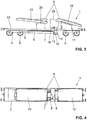
- FIGS 1 and 2 are perspective views of a material handling wagon 1 for the handling of bulk material, in particular of gravel, shown.
- Such Materialumschlagwagen 1 are typically used in conjunction with other cars in a train. The train is used for the renovation or rebuilding of railway tracks.
- the material handling trolley 1 comprises a frame 2, at least two drives 5 connected to the frame 2 and an upper conveyor track unit 6 which is connected to the frame 2. Furthermore, the material handling trolley 1 comprises a lower conveyor track unit 7, which likewise communicates with the frame 2.
- the frame 2 extends in a longitudinal direction L and a transverse direction Q.
- the frame 2 biases a frame plane R, which in the FIG. 1 symbolically represented on.
- the frame plane R has an upper side 3 and a lower side 4.
- the upper side 3 forms the upper side of the frame 2.
- the underside 4 of the frame 2 is here spaced from the frame plane R.
- the frame plane R can also lie at a different height in the frame 2 with respect to the frame 2 and becomes essentially for the definition of the arrangement of the individual components introduced on the frame 2.
- the frame plane R or the frame 2 or the longitudinal direction L and the transverse direction Q lie in the use of the material handling trolley 1 parallel to the ground, in particular to the tracks where the material handling trolley 1 stands or rolls.
- the upper conveyor track unit 6 is arranged on the upper side of the frame plane R or on the upper side 3 of the frame 2.
- the lower conveyor track unit 7 is arranged on the underside of the frame plane R or on the underside 4 of the frame 2.
- the upper conveyor track unit 6 is arranged above the frame 2 and the lower conveyor track unit 7 below the frame 2. In operation, it is possible to work selectively or in combination with the upper conveyor track unit 6 and / or the lower conveyor track unit 7.
- the conveyor track unit 7 comprises at least one conveyor belt, preferably at least two conveyor belts 8, 9.
- the conveyor belts 8, 9 are from an initial position to an angular, in particular vertical, to the frame plane R standing pivot axes A1 relative to the frame 2 in a pivoting position.
- the conveyor belt 8 in the starting position and the conveyor belt 9 in the Verschwenkstllung.
- Each of the conveyor belts 8, 9 of the lower conveyor track unit 7 is assigned a pivot axis. Both in the starting position and in the pivoting position, the conveyor belts 8, 9 can be used for the distribution of bulk material, as will be explained below.
- the conveyor belts 8, 9 are charged with the bulk material and then transport the Bulk material via a discharge edge 23 to the destination.
- the discharge edge 23 forms the front end of the corresponding conveyor belt 8, 9. Opposite the discharge edge 23, the conveyor belts 8, 9 are fed at a loading point 24 with the bulk material.
- the conveyor belts 8, 9 of the lower conveyor track unit 7 are optionally pivotable to the underside 4 of the frame plane R. In other words, the conveyor belts 8, 9 can be pivoted relative to the frame plane R, so that the conveyor belts 8, 9 are at an angle or inclined to the frame plane R.
- the conveyor belts 8, 9 of the lower conveyor track unit 7 are shown in their initial position. In the initial position, the conveyor belts 8, 9 extend in the longitudinal direction. The conveyor belts 8, 9 are arranged in such a way that they do not extend beyond the clearance profile of the material handling wagon 1 in the longitudinal direction L in the starting position. If the material handling wagon 1 is transported in conjunction with the construction train to a construction site, then the conveyor belts 8, 9 are in the starting position.
- the clearance gauge is defined essentially by the extension of the material handling wagon 1 in the transverse direction Q.
- exactly two conveyor belts 8, 9 are arranged, wherein in each case one conveyor belt 8 is arranged on the left on the frame 2 and another conveyor belt 9 on the right on the frame 2.
- One of the two discharge shafts 16 is directed to the lower conveyor track unit 7. That is, the conveyor belts 8, 9 of the lower conveyor track unit 7 are below the discharge shaft 16, wherein these conveyor belts 8, 9 are loaded via the discharge shaft 16 with the bulk material.
- the other of the discharge shafts 15 opens in the area below the frame 2 and is exposed, so that the bulk material can be added via the discharge shaft 15 directly to the route. The dispensing shaft 15 is thus not directed to the conveyor track unit 7.
- the silo unit 14 comprises at least one deflection element, in particular a flap which selectively directs the bulk material into one or the other of the two discharge shafts 15, 16.
- a deflection element in particular a flap which selectively directs the bulk material into one or the other of the two discharge shafts 15, 16.
- Other means for the allocation of the bulk material may also be provided.
- the silo unit 14 is formed separately, so that the silo unit has two different chambers, wherein the one chamber of the discharge shafts and the other chamber is assigned to the other of the discharge shafts, so that depending on the filling, the bulk material corresponding discharge shafts 14, 15 can be assigned.
- the frame 2 has an opening 10 in the region of the silo unit 14.
- the opening 10 extends here over larger parts of the frame 2.
- This breakthrough 10 the bulk of the silo unit from the top 3 of the frame, that is brought from above the frame plane R, the bottom 4 of the frame 2.
- parts of the silo unit 14 extend through the frame 2.
- here extend the two discharge shafts 15, 16 from the top 3 of the frame 2 through the frame 2 through and extend to the bottom 4 of the frame 2, where then the corresponding delivery points.
- the silo unit comprises a total of four discharge shafts 15, 16, which are offset from each other in the longitudinal direction L and in the transverse direction Q. Two of the discharge shafts, the discharge shafts with the reference numeral 15, are directed against the track. Two more of the discharge shafts, here the discharge shafts 16, are directed to the conveyor belts 8, 9 of the lower conveyor track unit 7.
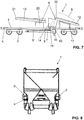
- the upper conveyor track unit 6, which is arranged on the upper side 3 of the frame 2 or on the upper side of the frame plane R of the frame 2, comprises a feed conveyor belt 12 and at least one unloading conveyor belt 13.
- the feed conveyor belt 12 serves to feed the unloading conveyor 13.
- the feed conveyor 12 is along the longitudinal direction L as a whole with respect to the fixed frame 2 movable.
- the infeed conveyor 12 is shown loading the silo unit 14.
- the feed conveyor 12 seen in the longitudinal direction L offset from the position in the FIG. 1 arranged and is positioned so that the unloading conveyor 13 can be fed.
- the feed conveyor 12 is loaded in operation with appropriate bulk material from other machines, such as. An excavator or a silo truck.
- the feed conveyor 12 is mounted here on a support structure 17. About this support structure 17, the feed conveyor belt 12 can be moved along the longitudinal direction.
- the support structure 17 has here an inclined to the frame plane R aligned guideway 18.
- the feed conveyor belt 12 is movably connected to the support structure 17 in connection.
- the feed conveyor belt 12 can be displaced along the longitudinal direction L, so that optionally the unloading conveyor belt 13 or the at least one silo unit 14 and thus the lower conveyor belt unit 7 or the route with the bulk material can be loaded.
- the silo unit 14 is substantially fixed to the frame 2 in connection.
- the feed conveyor 12 is itself relative to the frame 2 and thus also to the silo unit 14 displaceable, wherein the feed conveyor belt 12 is at least partially above the silo unit 14 and is movable over the silo unit 14.
- the feed conveyor belt 12 is therefore in the region of the silo unit 14 above the same. In the rear area, so outside the silo unit 14, the feed conveyor belt can also be below the silo unit 14, as in the FIG. 1 is shown accordingly.
- the silo unit 14 is located between the feed conveyor belt 12 and the unloading conveyor 13.
- the unloading conveyor 13 is pivotable from a starting position to a pivoting position.
- the unloading conveyor 13 is pivotable about an angle, in particular perpendicular, to the frame plane R standing pivot axis A2 in a pivoting position.
- the unloading conveyor 13 in the pivoting position.
- the unloading conveyor 13 In the initial position, the unloading conveyor 13 is located within the light profile of the material handling wagon in the longitudinal direction L.
- the unloading conveyor 13 extends in the pivoting position outside the clearance profile of the material handling wagon 1.
- the clearance profile is defined essentially by the extension of the material handling wagon 1 in the transverse direction Q.
- the feed conveyor belt 12 and the unloading conveyor 13 are inclined both in the starting position and in the pivoting position or at an angle to the frame plane R.
- the discharge conveyor 13 has in its rear region, where the bulk material impinges on the unloading conveyor 13, a retaining wall 19, which prevents in that the bulk material can fall back against the silo unit 14.
- the unloading conveyor 13 is connected to a hinge 20 with the frame 2, in particular with the top 3 of the frame 2, in connection.
- the hinge 20 is mounted accordingly on the upper side 3 of the frame 2.
- the frame 2 includes buffers 26 and couplings 27, so that the material handling wagon 1 can be connected to other railway wagons or a locomotive.
- the inventive material handling trolley 1 is shown in the transport position.
- the upper conveyor belt unit 6 and the lower conveyor belt unit 7 lie in such a way that they lie within the clearance profile and do not extend beyond the clearance of the material handling wagon 1. This is particularly true with respect to the transverse direction Q.
- the conveyor belt 8 and the conveyor belt 9 are parallel to each other and substantially parallel to the frame 2 with respect to the transverse direction Q.
- the unloading conveyor 13 lies in the longitudinal direction L aligned on the frame 2 and does not extend over the gauge with respect to the transverse direction seen in the longitudinal direction L out.
- the material handling wagon 1 can be transported in a train to a construction site.
- FIGS. 3 and 4 shown position the material handling wagon 1 can be transported in a train to a construction site.
- the material handling cart is shown in a first configuration.
- This is the possibility of Querablades of bulk material on the unloading conveyor belt 13.
- the unloading conveyor 13 is here at an angle, in particular at right angles, to the longitudinal direction L and projects beyond the space gauge with respect to the transverse direction Q on the frame 2 addition.
- the feed conveyor 12 is advanced so far forward in the direction of the unloading conveyor 13 that the bulk material passes from the feed conveyor 12 to the unloading conveyor 13.
- the bulk material now passes from the feed conveyor belt 12 along the direction of the arrow S to the unloading conveyor 13, where the bulk material is deflected by the angle of the unloading conveyor 13, essentially by 90 °.
- the bulk material S is further conveyed from the unloading conveyor belt 13 and finally reaches the discharge edge 21 of the unloading conveyor belt 13.
- the bulk material leaves the unloading conveyor belt 13 in the region of the discharge edge 21.
- the discharge edge 22 of the loading conveyor belt 12 lies here in the region of the unloading conveyor belt 13, as already mentioned above With the in the FIGS. 5 and 6 shown configuration, so the bulk material can be unloaded transversely to the longitudinal direction L.
- this configuration is used when the bulk material has to be loaded onto a wagon on an adjacent track or when the bulk goods are to be conveyed on a route which lies adjacent to the route on which the material handling wagon 1 stands.
- the unloading of the bulk material is shown on the route via the silo unit 14.
- the feed conveyor 12 is positioned so that the discharge edge 22 is above the silo unit 14.
- the unloading conveyor 13 and the conveyor belts 8, 9 of the lower conveyor track unit 7 are in the starting position.
- the bulk material is now fed via the feed conveyor belt 12 of the silo unit 14.
- corresponding slides or flaps are placed so that the bulk material is passed through the discharge shaft 16.
- the arrow S again shows the path of the bulk material in this configuration.
- the silo unit 14 can also be set such that the bulk material reaches the conveyor belts 8, 9 in the starting position, the bulk material then being conveyed by the conveyor belts 8, 9 in the longitudinal direction L.
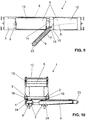
- FIGS. 9 and 10 another possible configuration of the material handling cart 1 is shown.
- one of the two conveyor belts 8, 9 of the lower conveyor belt unit 7 swung laterally and is in a pivoting position.
- the conveyor belt 8 is in the starting position.
- the feed conveyor belt 12 or the silo unit are set so that the bulk material can be fed to the conveyor belt 9 via the discharge shaft 15.
Landscapes
- Engineering & Computer Science (AREA)
- Mechanical Engineering (AREA)
- Architecture (AREA)
- Civil Engineering (AREA)
- Structural Engineering (AREA)
- Transportation (AREA)
- Aviation & Aerospace Engineering (AREA)
- Filling Or Emptying Of Bunkers, Hoppers, And Tanks (AREA)
- Structure Of Belt Conveyors (AREA)
- Intermediate Stations On Conveyors (AREA)
- Loading Or Unloading Of Vehicles (AREA)
Priority Applications (2)
| Application Number | Priority Date | Filing Date | Title |
|---|---|---|---|
| NO14753056A NO3041992T3 (enExample) | 2013-09-02 | 2014-08-15 | |
| EP14753056.2A EP3041992B1 (de) | 2013-09-02 | 2014-08-15 | Materialumschlagwagen |
Applications Claiming Priority (3)
| Application Number | Priority Date | Filing Date | Title |
|---|---|---|---|
| EP13182602 | 2013-09-02 | ||
| PCT/EP2014/067507 WO2015028321A1 (de) | 2013-09-02 | 2014-08-15 | Materialumschlagwagen |
| EP14753056.2A EP3041992B1 (de) | 2013-09-02 | 2014-08-15 | Materialumschlagwagen |
Publications (2)
| Publication Number | Publication Date |
|---|---|
| EP3041992A1 EP3041992A1 (de) | 2016-07-13 |
| EP3041992B1 true EP3041992B1 (de) | 2018-01-10 |
Family
ID=49080781
Family Applications (1)
| Application Number | Title | Priority Date | Filing Date |
|---|---|---|---|
| EP14753056.2A Not-in-force EP3041992B1 (de) | 2013-09-02 | 2014-08-15 | Materialumschlagwagen |
Country Status (10)
| Country | Link |
|---|---|
| US (1) | US9702093B2 (enExample) |
| EP (1) | EP3041992B1 (enExample) |
| AU (1) | AU2014314416B2 (enExample) |
| CA (1) | CA2922877A1 (enExample) |
| DK (1) | DK3041992T3 (enExample) |
| ES (1) | ES2660603T3 (enExample) |
| NO (1) | NO3041992T3 (enExample) |
| PT (1) | PT3041992T (enExample) |
| RU (1) | RU2668144C2 (enExample) |
| WO (1) | WO2015028321A1 (enExample) |
Families Citing this family (4)
| Publication number | Priority date | Publication date | Assignee | Title |
|---|---|---|---|---|
| CN109081084B (zh) * | 2018-07-02 | 2020-07-10 | 泾县凡泽科技服务有限公司 | 一种多用途传送箱 |
| US11267663B2 (en) | 2019-01-15 | 2022-03-08 | Quickthree Technology, Llc | Bottom dump pneumatic material handling system |
| DE102019101723A1 (de) * | 2019-01-24 | 2020-07-30 | K&K Maschinenentwicklungs GmbH & Co. KG | Eisenbahnwagen |
| DE202021106741U1 (de) * | 2021-12-10 | 2022-05-16 | Hans Hermann Bergmann | Schienengebundener Plattformwagen mit Förderband und Ladefläche |
Family Cites Families (22)
| Publication number | Priority date | Publication date | Assignee | Title |
|---|---|---|---|---|
| US2275799A (en) * | 1941-04-03 | 1942-03-10 | Oklejas Eli | Self-unloading trailer |
| US2410996A (en) * | 1944-03-15 | 1946-11-12 | Roy I Patterson | Grain unloading and loading mechanism |
| US3599785A (en) * | 1969-07-17 | 1971-08-17 | Jack S Stuart | Machine for removing litter from poultry houses |
| DE2146590A1 (de) * | 1970-09-17 | 1972-03-23 | Rossi, Lionello, Rom | Trichterwagen mit Vorrichtungen zum automatischen Beladen und Entladen |
| AT352770B (de) * | 1977-04-22 | 1979-10-10 | Plasser Bahnbaumasch Franz | Fahrbare einrichtung zur aufnahme von auf der gleisbettung liegenden kleineisenteilen |
| US4711403A (en) * | 1986-03-10 | 1987-12-08 | Gregory Sr Charles E | Method and apparatus for cleaning chicken manure from chicken houses |
| US4874283A (en) * | 1988-02-29 | 1989-10-17 | Tilcon Tomasso | Front dispensing truck with vertically and horizontally swingable screw conveyor |
| IT1235604B (it) * | 1989-09-22 | 1992-09-11 | Starfer Srl | Carro ferroviario per trasporto detriti |
| US5360097A (en) * | 1992-10-28 | 1994-11-01 | Granite Rock Company | Mobile conveyor system |
| US5819950A (en) * | 1996-04-05 | 1998-10-13 | Mccloskey; James Paschal | Portable trommel |
| US6113339A (en) * | 1997-12-31 | 2000-09-05 | Industrial Iron Works | Auger system for tender trailer |
| US6332736B1 (en) * | 1999-04-08 | 2001-12-25 | James Cape And Sons Company | Method and apparatus for spreading paving materials |
| RU11547U1 (ru) * | 1999-04-14 | 1999-10-16 | Проектно-технологическо-конструкторское бюро Главного управления пути МПС России | Щебнеочистительная машина |
| US6698594B2 (en) * | 2002-03-18 | 2004-03-02 | Ohio Central Steel Company | Screening machine |
| US7264104B2 (en) * | 2005-03-11 | 2007-09-04 | Johnson Crushers International | Crusher in-feed conveyor method and apparatus |
| US8033775B2 (en) * | 2005-08-05 | 2011-10-11 | Donelson Construction Co., Llc | Truck mounted bulk material transfer unit |
| WO2007065965A1 (en) * | 2005-12-09 | 2007-06-14 | Metso Minerals Inc. | Material processing apparatus comprising a conveyor |
| US7726904B2 (en) * | 2007-01-22 | 2010-06-01 | Rexius Forest By-Products, Inc. | Mobile conveying apparatus having a gear-to-gear driven swing assembly |
| US7584834B2 (en) * | 2007-12-24 | 2009-09-08 | Wood Gladys L | Portable articulating conveyor device and method of operating a portable articulating conveyor |
| US8132282B2 (en) * | 2008-04-24 | 2012-03-13 | 9089-1557 Quebec Inc. (Entretien De Stationnement M.A.) | Mechanical sweeper |
| US8573917B2 (en) * | 2008-08-15 | 2013-11-05 | Usc, L.L.C. | Bulk seed handling system |
| US9271472B2 (en) * | 2013-01-03 | 2016-03-01 | Louise Klemm Clark | Self-propelled stall cleaning apparatus |
-
2014
- 2014-08-15 NO NO14753056A patent/NO3041992T3/no unknown
- 2014-08-15 RU RU2016109481A patent/RU2668144C2/ru not_active IP Right Cessation
- 2014-08-15 CA CA2922877A patent/CA2922877A1/en not_active Abandoned
- 2014-08-15 WO PCT/EP2014/067507 patent/WO2015028321A1/de not_active Ceased
- 2014-08-15 DK DK14753056.2T patent/DK3041992T3/en active
- 2014-08-15 ES ES14753056.2T patent/ES2660603T3/es active Active
- 2014-08-15 US US14/915,462 patent/US9702093B2/en not_active Expired - Fee Related
- 2014-08-15 PT PT147530562T patent/PT3041992T/pt unknown
- 2014-08-15 EP EP14753056.2A patent/EP3041992B1/de not_active Not-in-force
- 2014-08-15 AU AU2014314416A patent/AU2014314416B2/en not_active Ceased
Also Published As
| Publication number | Publication date |
|---|---|
| RU2016109481A (ru) | 2017-10-09 |
| US9702093B2 (en) | 2017-07-11 |
| NO3041992T3 (enExample) | 2018-06-09 |
| AU2014314416B2 (en) | 2017-08-17 |
| EP3041992A1 (de) | 2016-07-13 |
| RU2668144C2 (ru) | 2018-09-26 |
| AU2014314416A1 (en) | 2016-03-03 |
| RU2016109481A3 (enExample) | 2018-03-06 |
| WO2015028321A1 (de) | 2015-03-05 |
| PT3041992T (pt) | 2018-04-13 |
| DK3041992T3 (en) | 2018-04-16 |
| CA2922877A1 (en) | 2015-03-05 |
| ES2660603T3 (es) | 2018-03-23 |
| US20160208443A1 (en) | 2016-07-21 |
Similar Documents
| Publication | Publication Date | Title |
|---|---|---|
| EP0599799B1 (de) | Verladewagen zum Transport von Schüttgut | |
| DD261618A5 (de) | Gleisverfahrbarer schuettgutverladewagen | |
| DE4306739B4 (de) | Transportwagen mit einem auf Schienenfahrwerken abgestützen Wagenrahmen | |
| EP2360316B1 (de) | Wagenverbund zur Materialförderung im Gleisbau | |
| EP3041992B1 (de) | Materialumschlagwagen | |
| EP2155966B1 (de) | Speicherwagen für schüttgut | |
| DE3219025C2 (de) | Transportzug für Gleisbehandlungszwecke und Verfahren zu dessen Befüllung und Entleerung | |
| EP1184248A2 (de) | Schüttgutverladewagen | |
| EP2295637B1 (de) | Vorrichtung zur Materialförderung im Gleisbau | |
| DE4141068C2 (de) | Mobile Betonmischanlage | |
| EP3283690B1 (de) | Speicherwagen für schüttgut | |
| EP2446086B1 (de) | Speicherwagen zum transport von schüttgut | |
| DE2758435C3 (de) | Gleisgebundener Wagen für Transport und Streuung von Schüttgut, insbesondere Böschungsmaterial | |
| EP2500470A2 (de) | Kopfarbeitswagen | |
| EP2125475B1 (de) | Speicherwagen | |
| EP3145784B1 (de) | Schüttgutverladewagen | |
| EP3440261B1 (de) | Verfahren zum be- und entladen eines gleisverfahrbaren transportfahrzeuges | |
| DE202009011149U1 (de) | Vorrichtung zur Materialförderung im Gleisbau | |
| EP2022896A1 (de) | Gleisverfahrbarer Schüttgutverladewagen | |
| DE2649610A1 (de) | Vorrichtung zum entladen von vorratsbehaeltern, bunkern oder fuelltrichtern oder aehnlichen behaeltern von strassen- oder eisenbahnfahrzeugen | |
| AT375048B (de) | Schienengebundener transportwagen fuer schuettgueter | |
| EP3475486B1 (de) | Materialförderwagenverband und verfahren zum beladen des materialförderwagenverbands | |
| DE102023104199A1 (de) | Verfahren zur Herstellung einer Betondecke für eine Fahrbahn oder dergleichen und Verwendung eines Abschiebewagens für die Herstellung der Betondecke | |
| DE4309811A1 (de) | Schüttgutwagen | |
| DE3506776A1 (de) | Fertiger zum herstellen eines schotterbettes fuer eisenbahngleise |
Legal Events
| Date | Code | Title | Description |
|---|---|---|---|
| PUAI | Public reference made under article 153(3) epc to a published international application that has entered the european phase |
Free format text: ORIGINAL CODE: 0009012 |
|
| 17P | Request for examination filed |
Effective date: 20160211 |
|
| AK | Designated contracting states |
Kind code of ref document: A1 Designated state(s): AL AT BE BG CH CY CZ DE DK EE ES FI FR GB GR HR HU IE IS IT LI LT LU LV MC MK MT NL NO PL PT RO RS SE SI SK SM TR |
|
| AX | Request for extension of the european patent |
Extension state: BA ME |
|
| DAX | Request for extension of the european patent (deleted) | ||
| GRAP | Despatch of communication of intention to grant a patent |
Free format text: ORIGINAL CODE: EPIDOSNIGR1 |
|
| INTG | Intention to grant announced |
Effective date: 20170804 |
|
| GRAS | Grant fee paid |
Free format text: ORIGINAL CODE: EPIDOSNIGR3 |
|
| GRAA | (expected) grant |
Free format text: ORIGINAL CODE: 0009210 |
|
| AK | Designated contracting states |
Kind code of ref document: B1 Designated state(s): AL AT BE BG CH CY CZ DE DK EE ES FI FR GB GR HR HU IE IS IT LI LT LU LV MC MK MT NL NO PL PT RO RS SE SI SK SM TR |
|
| REG | Reference to a national code |
Ref country code: CH Ref legal event code: EP Ref country code: AT Ref legal event code: REF Ref document number: 962566 Country of ref document: AT Kind code of ref document: T Effective date: 20180115 |
|
| REG | Reference to a national code |
Ref country code: IE Ref legal event code: FG4D Free format text: LANGUAGE OF EP DOCUMENT: GERMAN |
|
| REG | Reference to a national code |
Ref country code: DE Ref legal event code: R096 Ref document number: 502014006904 Country of ref document: DE |
|
| REG | Reference to a national code |
Ref country code: ES Ref legal event code: FG2A Ref document number: 2660603 Country of ref document: ES Kind code of ref document: T3 Effective date: 20180323 |
|
| REG | Reference to a national code |
Ref country code: CH Ref legal event code: NV Representative=s name: ISLER AND PEDRAZZINI AG, CH |
|
| REG | Reference to a national code |
Ref country code: NL Ref legal event code: FP |
|
| REG | Reference to a national code |
Ref country code: SE Ref legal event code: TRGR |
|
| REG | Reference to a national code |
Ref country code: PT Ref legal event code: SC4A Ref document number: 3041992 Country of ref document: PT Date of ref document: 20180413 Kind code of ref document: T Free format text: AVAILABILITY OF NATIONAL TRANSLATION Effective date: 20180404 |
|
| REG | Reference to a national code |
Ref country code: DK Ref legal event code: T3 Effective date: 20180413 |
|
| REG | Reference to a national code |
Ref country code: NO Ref legal event code: T2 Effective date: 20180110 |
|
| PG25 | Lapsed in a contracting state [announced via postgrant information from national office to epo] |
Ref country code: HR Free format text: LAPSE BECAUSE OF FAILURE TO SUBMIT A TRANSLATION OF THE DESCRIPTION OR TO PAY THE FEE WITHIN THE PRESCRIBED TIME-LIMIT Effective date: 20180110 Ref country code: LT Free format text: LAPSE BECAUSE OF FAILURE TO SUBMIT A TRANSLATION OF THE DESCRIPTION OR TO PAY THE FEE WITHIN THE PRESCRIBED TIME-LIMIT Effective date: 20180110 Ref country code: CY Free format text: LAPSE BECAUSE OF FAILURE TO SUBMIT A TRANSLATION OF THE DESCRIPTION OR TO PAY THE FEE WITHIN THE PRESCRIBED TIME-LIMIT Effective date: 20180110 |
|
| REG | Reference to a national code |
Ref country code: FR Ref legal event code: PLFP Year of fee payment: 5 |
|
| PG25 | Lapsed in a contracting state [announced via postgrant information from national office to epo] |
Ref country code: IS Free format text: LAPSE BECAUSE OF FAILURE TO SUBMIT A TRANSLATION OF THE DESCRIPTION OR TO PAY THE FEE WITHIN THE PRESCRIBED TIME-LIMIT Effective date: 20180510 Ref country code: LV Free format text: LAPSE BECAUSE OF FAILURE TO SUBMIT A TRANSLATION OF THE DESCRIPTION OR TO PAY THE FEE WITHIN THE PRESCRIBED TIME-LIMIT Effective date: 20180110 Ref country code: PL Free format text: LAPSE BECAUSE OF FAILURE TO SUBMIT A TRANSLATION OF THE DESCRIPTION OR TO PAY THE FEE WITHIN THE PRESCRIBED TIME-LIMIT Effective date: 20180110 Ref country code: GR Free format text: LAPSE BECAUSE OF FAILURE TO SUBMIT A TRANSLATION OF THE DESCRIPTION OR TO PAY THE FEE WITHIN THE PRESCRIBED TIME-LIMIT Effective date: 20180411 Ref country code: RS Free format text: LAPSE BECAUSE OF FAILURE TO SUBMIT A TRANSLATION OF THE DESCRIPTION OR TO PAY THE FEE WITHIN THE PRESCRIBED TIME-LIMIT Effective date: 20180110 Ref country code: BG Free format text: LAPSE BECAUSE OF FAILURE TO SUBMIT A TRANSLATION OF THE DESCRIPTION OR TO PAY THE FEE WITHIN THE PRESCRIBED TIME-LIMIT Effective date: 20180410 |
|
| PG25 | Lapsed in a contracting state [announced via postgrant information from national office to epo] |
Ref country code: MT Free format text: LAPSE BECAUSE OF FAILURE TO SUBMIT A TRANSLATION OF THE DESCRIPTION OR TO PAY THE FEE WITHIN THE PRESCRIBED TIME-LIMIT Effective date: 20180110 |
|
| PGFP | Annual fee paid to national office [announced via postgrant information from national office to epo] |
Ref country code: LU Payment date: 20180821 Year of fee payment: 5 |
|
| REG | Reference to a national code |
Ref country code: DE Ref legal event code: R097 Ref document number: 502014006904 Country of ref document: DE |
|
| PG25 | Lapsed in a contracting state [announced via postgrant information from national office to epo] |
Ref country code: AL Free format text: LAPSE BECAUSE OF FAILURE TO SUBMIT A TRANSLATION OF THE DESCRIPTION OR TO PAY THE FEE WITHIN THE PRESCRIBED TIME-LIMIT Effective date: 20180110 Ref country code: EE Free format text: LAPSE BECAUSE OF FAILURE TO SUBMIT A TRANSLATION OF THE DESCRIPTION OR TO PAY THE FEE WITHIN THE PRESCRIBED TIME-LIMIT Effective date: 20180110 Ref country code: RO Free format text: LAPSE BECAUSE OF FAILURE TO SUBMIT A TRANSLATION OF THE DESCRIPTION OR TO PAY THE FEE WITHIN THE PRESCRIBED TIME-LIMIT Effective date: 20180110 |
|
| PGFP | Annual fee paid to national office [announced via postgrant information from national office to epo] |
Ref country code: RO Payment date: 20180524 Year of fee payment: 8 Ref country code: ES Payment date: 20180921 Year of fee payment: 5 Ref country code: FR Payment date: 20180827 Year of fee payment: 5 Ref country code: IT Payment date: 20180823 Year of fee payment: 5 Ref country code: NO Payment date: 20180827 Year of fee payment: 5 Ref country code: IE Payment date: 20180828 Year of fee payment: 5 |
|
| PLBE | No opposition filed within time limit |
Free format text: ORIGINAL CODE: 0009261 |
|
| STAA | Information on the status of an ep patent application or granted ep patent |
Free format text: STATUS: NO OPPOSITION FILED WITHIN TIME LIMIT |
|
| PG25 | Lapsed in a contracting state [announced via postgrant information from national office to epo] |
Ref country code: SM Free format text: LAPSE BECAUSE OF FAILURE TO SUBMIT A TRANSLATION OF THE DESCRIPTION OR TO PAY THE FEE WITHIN THE PRESCRIBED TIME-LIMIT Effective date: 20180110 Ref country code: CZ Free format text: LAPSE BECAUSE OF FAILURE TO SUBMIT A TRANSLATION OF THE DESCRIPTION OR TO PAY THE FEE WITHIN THE PRESCRIBED TIME-LIMIT Effective date: 20180110 Ref country code: SK Free format text: LAPSE BECAUSE OF FAILURE TO SUBMIT A TRANSLATION OF THE DESCRIPTION OR TO PAY THE FEE WITHIN THE PRESCRIBED TIME-LIMIT Effective date: 20180110 |
|
| PGFP | Annual fee paid to national office [announced via postgrant information from national office to epo] |
Ref country code: BE Payment date: 20180821 Year of fee payment: 5 Ref country code: SE Payment date: 20180823 Year of fee payment: 5 Ref country code: DK Payment date: 20180823 Year of fee payment: 5 |
|
| 26N | No opposition filed |
Effective date: 20181011 |
|
| PGFP | Annual fee paid to national office [announced via postgrant information from national office to epo] |
Ref country code: PT Payment date: 20180719 Year of fee payment: 5 |
|
| PG25 | Lapsed in a contracting state [announced via postgrant information from national office to epo] |
Ref country code: SI Free format text: LAPSE BECAUSE OF FAILURE TO SUBMIT A TRANSLATION OF THE DESCRIPTION OR TO PAY THE FEE WITHIN THE PRESCRIBED TIME-LIMIT Effective date: 20180110 |
|
| PG25 | Lapsed in a contracting state [announced via postgrant information from national office to epo] |
Ref country code: MC Free format text: LAPSE BECAUSE OF FAILURE TO SUBMIT A TRANSLATION OF THE DESCRIPTION OR TO PAY THE FEE WITHIN THE PRESCRIBED TIME-LIMIT Effective date: 20180110 |
|
| REG | Reference to a national code |
Ref country code: NO Ref legal event code: MMEP |
|
| REG | Reference to a national code |
Ref country code: FI Ref legal event code: MAE |
|
| PG25 | Lapsed in a contracting state [announced via postgrant information from national office to epo] |
Ref country code: TR Free format text: LAPSE BECAUSE OF FAILURE TO SUBMIT A TRANSLATION OF THE DESCRIPTION OR TO PAY THE FEE WITHIN THE PRESCRIBED TIME-LIMIT Effective date: 20180110 |
|
| REG | Reference to a national code |
Ref country code: DK Ref legal event code: EBP Effective date: 20190831 |
|
| REG | Reference to a national code |
Ref country code: NL Ref legal event code: MM Effective date: 20190901 |
|
| REG | Reference to a national code |
Ref country code: SE Ref legal event code: EUG |
|
| PG25 | Lapsed in a contracting state [announced via postgrant information from national office to epo] |
Ref country code: NO Free format text: LAPSE BECAUSE OF NON-PAYMENT OF DUE FEES Effective date: 20190831 Ref country code: SE Free format text: LAPSE BECAUSE OF NON-PAYMENT OF DUE FEES Effective date: 20190816 Ref country code: FI Free format text: LAPSE BECAUSE OF NON-PAYMENT OF DUE FEES Effective date: 20190815 Ref country code: PT Free format text: LAPSE BECAUSE OF NON-PAYMENT OF DUE FEES Effective date: 20200217 |
|
| PG25 | Lapsed in a contracting state [announced via postgrant information from national office to epo] |
Ref country code: LU Free format text: LAPSE BECAUSE OF NON-PAYMENT OF DUE FEES Effective date: 20190815 |
|
| REG | Reference to a national code |
Ref country code: BE Ref legal event code: MM Effective date: 20190831 |
|
| PG25 | Lapsed in a contracting state [announced via postgrant information from national office to epo] |
Ref country code: HU Free format text: LAPSE BECAUSE OF FAILURE TO SUBMIT A TRANSLATION OF THE DESCRIPTION OR TO PAY THE FEE WITHIN THE PRESCRIBED TIME-LIMIT; INVALID AB INITIO Effective date: 20140815 Ref country code: MK Free format text: LAPSE BECAUSE OF NON-PAYMENT OF DUE FEES Effective date: 20180110 |
|
| PG25 | Lapsed in a contracting state [announced via postgrant information from national office to epo] |
Ref country code: NL Free format text: LAPSE BECAUSE OF NON-PAYMENT OF DUE FEES Effective date: 20190901 Ref country code: FR Free format text: LAPSE BECAUSE OF NON-PAYMENT OF DUE FEES Effective date: 20190831 Ref country code: IE Free format text: LAPSE BECAUSE OF NON-PAYMENT OF DUE FEES Effective date: 20190815 Ref country code: DK Free format text: LAPSE BECAUSE OF NON-PAYMENT OF DUE FEES Effective date: 20190831 |
|
| PG25 | Lapsed in a contracting state [announced via postgrant information from national office to epo] |
Ref country code: BE Free format text: LAPSE BECAUSE OF NON-PAYMENT OF DUE FEES Effective date: 20190831 Ref country code: IT Free format text: LAPSE BECAUSE OF NON-PAYMENT OF DUE FEES Effective date: 20190815 |
|
| PGFP | Annual fee paid to national office [announced via postgrant information from national office to epo] |
Ref country code: GB Payment date: 20200826 Year of fee payment: 7 Ref country code: DE Payment date: 20200819 Year of fee payment: 7 |
|
| PGFP | Annual fee paid to national office [announced via postgrant information from national office to epo] |
Ref country code: CH Payment date: 20200811 Year of fee payment: 7 Ref country code: AT Payment date: 20200820 Year of fee payment: 7 |
|
| REG | Reference to a national code |
Ref country code: ES Ref legal event code: FD2A Effective date: 20210105 |
|
| PG25 | Lapsed in a contracting state [announced via postgrant information from national office to epo] |
Ref country code: ES Free format text: LAPSE BECAUSE OF NON-PAYMENT OF DUE FEES Effective date: 20190816 |
|
| REG | Reference to a national code |
Ref country code: DE Ref legal event code: R119 Ref document number: 502014006904 Country of ref document: DE |
|
| REG | Reference to a national code |
Ref country code: CH Ref legal event code: PL |
|
| REG | Reference to a national code |
Ref country code: AT Ref legal event code: MM01 Ref document number: 962566 Country of ref document: AT Kind code of ref document: T Effective date: 20210815 |
|
| GBPC | Gb: european patent ceased through non-payment of renewal fee |
Effective date: 20210815 |
|
| PG25 | Lapsed in a contracting state [announced via postgrant information from national office to epo] |
Ref country code: LI Free format text: LAPSE BECAUSE OF NON-PAYMENT OF DUE FEES Effective date: 20210831 Ref country code: CH Free format text: LAPSE BECAUSE OF NON-PAYMENT OF DUE FEES Effective date: 20210831 Ref country code: AT Free format text: LAPSE BECAUSE OF NON-PAYMENT OF DUE FEES Effective date: 20210815 |
|
| PG25 | Lapsed in a contracting state [announced via postgrant information from national office to epo] |
Ref country code: GB Free format text: LAPSE BECAUSE OF NON-PAYMENT OF DUE FEES Effective date: 20210815 Ref country code: DE Free format text: LAPSE BECAUSE OF NON-PAYMENT OF DUE FEES Effective date: 20220301 |