EP3041809B1 - Leitfähiges targetmaterial - Google Patents
Leitfähiges targetmaterial Download PDFInfo
- Publication number
- EP3041809B1 EP3041809B1 EP14789129.5A EP14789129A EP3041809B1 EP 3041809 B1 EP3041809 B1 EP 3041809B1 EP 14789129 A EP14789129 A EP 14789129A EP 3041809 B1 EP3041809 B1 EP 3041809B1
- Authority
- EP
- European Patent Office
- Prior art keywords
- target material
- material according
- carbon
- conductive target
- conductive
- Prior art date
- Legal status (The legal status is an assumption and is not a legal conclusion. Google has not performed a legal analysis and makes no representation as to the accuracy of the status listed.)
- Active
Links
Images

Classifications
-
- F—MECHANICAL ENGINEERING; LIGHTING; HEATING; WEAPONS; BLASTING
- F27—FURNACES; KILNS; OVENS; RETORTS
- F27B—FURNACES, KILNS, OVENS OR RETORTS IN GENERAL; OPEN SINTERING OR LIKE APPARATUS
- F27B7/00—Rotary-drum furnaces, i.e. horizontal or slightly inclined
- F27B7/20—Details, accessories or equipment specially adapted for rotary-drum furnaces
- F27B7/34—Arrangements of heating devices
-
- H—ELECTRICITY
- H01—ELECTRIC ELEMENTS
- H01J—ELECTRIC DISCHARGE TUBES OR DISCHARGE LAMPS
- H01J37/00—Discharge tubes with provision for introducing objects or material to be exposed to the discharge, e.g. for the purpose of examination or processing thereof
- H01J37/32—Gas-filled discharge tubes
- H01J37/34—Gas-filled discharge tubes operating with cathodic sputtering
- H01J37/3411—Constructional aspects of the reactor
- H01J37/3414—Targets
- H01J37/3426—Material
- H01J37/3429—Plural materials
-
- C—CHEMISTRY; METALLURGY
- C04—CEMENTS; CONCRETE; ARTIFICIAL STONE; CERAMICS; REFRACTORIES
- C04B—LIME, MAGNESIA; SLAG; CEMENTS; COMPOSITIONS THEREOF, e.g. MORTARS, CONCRETE OR LIKE BUILDING MATERIALS; ARTIFICIAL STONE; CERAMICS; REFRACTORIES; TREATMENT OF NATURAL STONE
- C04B35/00—Shaped ceramic products characterised by their composition; Ceramics compositions; Processing powders of inorganic compounds preparatory to the manufacturing of ceramic products
- C04B35/01—Shaped ceramic products characterised by their composition; Ceramics compositions; Processing powders of inorganic compounds preparatory to the manufacturing of ceramic products based on oxide ceramics
- C04B35/013—Shaped ceramic products characterised by their composition; Ceramics compositions; Processing powders of inorganic compounds preparatory to the manufacturing of ceramic products based on oxide ceramics containing carbon
-
- C—CHEMISTRY; METALLURGY
- C04—CEMENTS; CONCRETE; ARTIFICIAL STONE; CERAMICS; REFRACTORIES
- C04B—LIME, MAGNESIA; SLAG; CEMENTS; COMPOSITIONS THEREOF, e.g. MORTARS, CONCRETE OR LIKE BUILDING MATERIALS; ARTIFICIAL STONE; CERAMICS; REFRACTORIES; TREATMENT OF NATURAL STONE
- C04B35/00—Shaped ceramic products characterised by their composition; Ceramics compositions; Processing powders of inorganic compounds preparatory to the manufacturing of ceramic products
- C04B35/01—Shaped ceramic products characterised by their composition; Ceramics compositions; Processing powders of inorganic compounds preparatory to the manufacturing of ceramic products based on oxide ceramics
- C04B35/447—Shaped ceramic products characterised by their composition; Ceramics compositions; Processing powders of inorganic compounds preparatory to the manufacturing of ceramic products based on oxide ceramics based on phosphates, e.g. hydroxyapatite
-
- C—CHEMISTRY; METALLURGY
- C04—CEMENTS; CONCRETE; ARTIFICIAL STONE; CERAMICS; REFRACTORIES
- C04B—LIME, MAGNESIA; SLAG; CEMENTS; COMPOSITIONS THEREOF, e.g. MORTARS, CONCRETE OR LIKE BUILDING MATERIALS; ARTIFICIAL STONE; CERAMICS; REFRACTORIES; TREATMENT OF NATURAL STONE
- C04B35/00—Shaped ceramic products characterised by their composition; Ceramics compositions; Processing powders of inorganic compounds preparatory to the manufacturing of ceramic products
- C04B35/515—Shaped ceramic products characterised by their composition; Ceramics compositions; Processing powders of inorganic compounds preparatory to the manufacturing of ceramic products based on non-oxide ceramics
- C04B35/52—Shaped ceramic products characterised by their composition; Ceramics compositions; Processing powders of inorganic compounds preparatory to the manufacturing of ceramic products based on non-oxide ceramics based on carbon, e.g. graphite
-
- C—CHEMISTRY; METALLURGY
- C04—CEMENTS; CONCRETE; ARTIFICIAL STONE; CERAMICS; REFRACTORIES
- C04B—LIME, MAGNESIA; SLAG; CEMENTS; COMPOSITIONS THEREOF, e.g. MORTARS, CONCRETE OR LIKE BUILDING MATERIALS; ARTIFICIAL STONE; CERAMICS; REFRACTORIES; TREATMENT OF NATURAL STONE
- C04B35/00—Shaped ceramic products characterised by their composition; Ceramics compositions; Processing powders of inorganic compounds preparatory to the manufacturing of ceramic products
- C04B35/622—Forming processes; Processing powders of inorganic compounds preparatory to the manufacturing of ceramic products
- C04B35/64—Burning or sintering processes
- C04B35/645—Pressure sintering
-
- C—CHEMISTRY; METALLURGY
- C23—COATING METALLIC MATERIAL; COATING MATERIAL WITH METALLIC MATERIAL; CHEMICAL SURFACE TREATMENT; DIFFUSION TREATMENT OF METALLIC MATERIAL; COATING BY VACUUM EVAPORATION, BY SPUTTERING, BY ION IMPLANTATION OR BY CHEMICAL VAPOUR DEPOSITION, IN GENERAL; INHIBITING CORROSION OF METALLIC MATERIAL OR INCRUSTATION IN GENERAL
- C23C—COATING METALLIC MATERIAL; COATING MATERIAL WITH METALLIC MATERIAL; SURFACE TREATMENT OF METALLIC MATERIAL BY DIFFUSION INTO THE SURFACE, BY CHEMICAL CONVERSION OR SUBSTITUTION; COATING BY VACUUM EVAPORATION, BY SPUTTERING, BY ION IMPLANTATION OR BY CHEMICAL VAPOUR DEPOSITION, IN GENERAL
- C23C14/00—Coating by vacuum evaporation, by sputtering or by ion implantation of the coating forming material
- C23C14/06—Coating by vacuum evaporation, by sputtering or by ion implantation of the coating forming material characterised by the coating material
- C23C14/0605—Carbon
-
- C—CHEMISTRY; METALLURGY
- C23—COATING METALLIC MATERIAL; COATING MATERIAL WITH METALLIC MATERIAL; CHEMICAL SURFACE TREATMENT; DIFFUSION TREATMENT OF METALLIC MATERIAL; COATING BY VACUUM EVAPORATION, BY SPUTTERING, BY ION IMPLANTATION OR BY CHEMICAL VAPOUR DEPOSITION, IN GENERAL; INHIBITING CORROSION OF METALLIC MATERIAL OR INCRUSTATION IN GENERAL
- C23C—COATING METALLIC MATERIAL; COATING MATERIAL WITH METALLIC MATERIAL; SURFACE TREATMENT OF METALLIC MATERIAL BY DIFFUSION INTO THE SURFACE, BY CHEMICAL CONVERSION OR SUBSTITUTION; COATING BY VACUUM EVAPORATION, BY SPUTTERING, BY ION IMPLANTATION OR BY CHEMICAL VAPOUR DEPOSITION, IN GENERAL
- C23C14/00—Coating by vacuum evaporation, by sputtering or by ion implantation of the coating forming material
- C23C14/22—Coating by vacuum evaporation, by sputtering or by ion implantation of the coating forming material characterised by the process of coating
- C23C14/34—Sputtering
- C23C14/3407—Cathode assembly for sputtering apparatus, e.g. Target
- C23C14/3414—Metallurgical or chemical aspects of target preparation, e.g. casting, powder metallurgy
-
- F—MECHANICAL ENGINEERING; LIGHTING; HEATING; WEAPONS; BLASTING
- F23—COMBUSTION APPARATUS; COMBUSTION PROCESSES
- F23C—METHODS OR APPARATUS FOR COMBUSTION USING FLUID FUEL OR SOLID FUEL SUSPENDED IN A CARRIER GAS OR AIR
- F23C1/00—Combustion apparatus specially adapted for combustion of two or more kinds of fuel simultaneously or alternately, at least one kind of fuel being either a fluid fuel or a solid fuel suspended in a carrier gas or air
- F23C1/02—Combustion apparatus specially adapted for combustion of two or more kinds of fuel simultaneously or alternately, at least one kind of fuel being either a fluid fuel or a solid fuel suspended in a carrier gas or air lump and liquid fuel
-
- F—MECHANICAL ENGINEERING; LIGHTING; HEATING; WEAPONS; BLASTING
- F23—COMBUSTION APPARATUS; COMBUSTION PROCESSES
- F23C—METHODS OR APPARATUS FOR COMBUSTION USING FLUID FUEL OR SOLID FUEL SUSPENDED IN A CARRIER GAS OR AIR
- F23C1/00—Combustion apparatus specially adapted for combustion of two or more kinds of fuel simultaneously or alternately, at least one kind of fuel being either a fluid fuel or a solid fuel suspended in a carrier gas or air
- F23C1/06—Combustion apparatus specially adapted for combustion of two or more kinds of fuel simultaneously or alternately, at least one kind of fuel being either a fluid fuel or a solid fuel suspended in a carrier gas or air lump and pulverulent fuel
-
- F—MECHANICAL ENGINEERING; LIGHTING; HEATING; WEAPONS; BLASTING
- F23—COMBUSTION APPARATUS; COMBUSTION PROCESSES
- F23C—METHODS OR APPARATUS FOR COMBUSTION USING FLUID FUEL OR SOLID FUEL SUSPENDED IN A CARRIER GAS OR AIR
- F23C1/00—Combustion apparatus specially adapted for combustion of two or more kinds of fuel simultaneously or alternately, at least one kind of fuel being either a fluid fuel or a solid fuel suspended in a carrier gas or air
- F23C1/10—Combustion apparatus specially adapted for combustion of two or more kinds of fuel simultaneously or alternately, at least one kind of fuel being either a fluid fuel or a solid fuel suspended in a carrier gas or air liquid and pulverulent fuel
-
- F—MECHANICAL ENGINEERING; LIGHTING; HEATING; WEAPONS; BLASTING
- F23—COMBUSTION APPARATUS; COMBUSTION PROCESSES
- F23C—METHODS OR APPARATUS FOR COMBUSTION USING FLUID FUEL OR SOLID FUEL SUSPENDED IN A CARRIER GAS OR AIR
- F23C5/00—Disposition of burners with respect to the combustion chamber or to one another; Mounting of burners in combustion apparatus
- F23C5/08—Disposition of burners
-
- F—MECHANICAL ENGINEERING; LIGHTING; HEATING; WEAPONS; BLASTING
- F23—COMBUSTION APPARATUS; COMBUSTION PROCESSES
- F23D—BURNERS
- F23D1/00—Burners for combustion of pulverulent fuel
-
- F—MECHANICAL ENGINEERING; LIGHTING; HEATING; WEAPONS; BLASTING
- F23—COMBUSTION APPARATUS; COMBUSTION PROCESSES
- F23D—BURNERS
- F23D17/00—Burners for combustion simultaneously or alternately of gaseous or liquid or pulverulent fuel
- F23D17/007—Burners for combustion simultaneously or alternately of gaseous or liquid or pulverulent fuel liquid or pulverulent fuel
-
- F—MECHANICAL ENGINEERING; LIGHTING; HEATING; WEAPONS; BLASTING
- F23—COMBUSTION APPARATUS; COMBUSTION PROCESSES
- F23K—FEEDING FUEL TO COMBUSTION APPARATUS
- F23K3/00—Feeding or distributing of lump or pulverulent fuel to combustion apparatus
- F23K3/02—Pneumatic feeding arrangements, i.e. by air blast
-
- F—MECHANICAL ENGINEERING; LIGHTING; HEATING; WEAPONS; BLASTING
- F27—FURNACES; KILNS; OVENS; RETORTS
- F27B—FURNACES, KILNS, OVENS OR RETORTS IN GENERAL; OPEN SINTERING OR LIKE APPARATUS
- F27B7/00—Rotary-drum furnaces, i.e. horizontal or slightly inclined
- F27B7/20—Details, accessories or equipment specially adapted for rotary-drum furnaces
- F27B7/36—Arrangements of air or gas supply devices
-
- F—MECHANICAL ENGINEERING; LIGHTING; HEATING; WEAPONS; BLASTING
- F27—FURNACES; KILNS; OVENS; RETORTS
- F27D—DETAILS OR ACCESSORIES OF FURNACES, KILNS, OVENS OR RETORTS, IN SO FAR AS THEY ARE OF KINDS OCCURRING IN MORE THAN ONE KIND OF FURNACE
- F27D99/00—Subject matter not provided for in other groups of this subclass
- F27D99/0001—Heating elements or systems
- F27D99/0033—Heating elements or systems using burners
-
- H—ELECTRICITY
- H01—ELECTRIC ELEMENTS
- H01M—PROCESSES OR MEANS, e.g. BATTERIES, FOR THE DIRECT CONVERSION OF CHEMICAL ENERGY INTO ELECTRICAL ENERGY
- H01M10/00—Secondary cells; Manufacture thereof
- H01M10/05—Accumulators with non-aqueous electrolyte
- H01M10/052—Li-accumulators
-
- C—CHEMISTRY; METALLURGY
- C04—CEMENTS; CONCRETE; ARTIFICIAL STONE; CERAMICS; REFRACTORIES
- C04B—LIME, MAGNESIA; SLAG; CEMENTS; COMPOSITIONS THEREOF, e.g. MORTARS, CONCRETE OR LIKE BUILDING MATERIALS; ARTIFICIAL STONE; CERAMICS; REFRACTORIES; TREATMENT OF NATURAL STONE
- C04B2235/00—Aspects relating to ceramic starting mixtures or sintered ceramic products
- C04B2235/02—Composition of constituents of the starting material or of secondary phases of the final product
- C04B2235/30—Constituents and secondary phases not being of a fibrous nature
- C04B2235/32—Metal oxides, mixed metal oxides, or oxide-forming salts thereof, e.g. carbonates, nitrates, (oxy)hydroxides, chlorides
- C04B2235/3201—Alkali metal oxides or oxide-forming salts thereof
- C04B2235/3203—Lithium oxide or oxide-forming salts thereof
-
- C—CHEMISTRY; METALLURGY
- C04—CEMENTS; CONCRETE; ARTIFICIAL STONE; CERAMICS; REFRACTORIES
- C04B—LIME, MAGNESIA; SLAG; CEMENTS; COMPOSITIONS THEREOF, e.g. MORTARS, CONCRETE OR LIKE BUILDING MATERIALS; ARTIFICIAL STONE; CERAMICS; REFRACTORIES; TREATMENT OF NATURAL STONE
- C04B2235/00—Aspects relating to ceramic starting mixtures or sintered ceramic products
- C04B2235/02—Composition of constituents of the starting material or of secondary phases of the final product
- C04B2235/30—Constituents and secondary phases not being of a fibrous nature
- C04B2235/42—Non metallic elements added as constituents or additives, e.g. sulfur, phosphor, selenium or tellurium
- C04B2235/422—Carbon
-
- C—CHEMISTRY; METALLURGY
- C04—CEMENTS; CONCRETE; ARTIFICIAL STONE; CERAMICS; REFRACTORIES
- C04B—LIME, MAGNESIA; SLAG; CEMENTS; COMPOSITIONS THEREOF, e.g. MORTARS, CONCRETE OR LIKE BUILDING MATERIALS; ARTIFICIAL STONE; CERAMICS; REFRACTORIES; TREATMENT OF NATURAL STONE
- C04B2235/00—Aspects relating to ceramic starting mixtures or sintered ceramic products
- C04B2235/02—Composition of constituents of the starting material or of secondary phases of the final product
- C04B2235/50—Constituents or additives of the starting mixture chosen for their shape or used because of their shape or their physical appearance
- C04B2235/54—Particle size related information
- C04B2235/5418—Particle size related information expressed by the size of the particles or aggregates thereof
- C04B2235/5436—Particle size related information expressed by the size of the particles or aggregates thereof micrometer sized, i.e. from 1 to 100 micron
-
- C—CHEMISTRY; METALLURGY
- C04—CEMENTS; CONCRETE; ARTIFICIAL STONE; CERAMICS; REFRACTORIES
- C04B—LIME, MAGNESIA; SLAG; CEMENTS; COMPOSITIONS THEREOF, e.g. MORTARS, CONCRETE OR LIKE BUILDING MATERIALS; ARTIFICIAL STONE; CERAMICS; REFRACTORIES; TREATMENT OF NATURAL STONE
- C04B2235/00—Aspects relating to ceramic starting mixtures or sintered ceramic products
- C04B2235/02—Composition of constituents of the starting material or of secondary phases of the final product
- C04B2235/50—Constituents or additives of the starting mixture chosen for their shape or used because of their shape or their physical appearance
- C04B2235/54—Particle size related information
- C04B2235/5463—Particle size distributions
-
- C—CHEMISTRY; METALLURGY
- C04—CEMENTS; CONCRETE; ARTIFICIAL STONE; CERAMICS; REFRACTORIES
- C04B—LIME, MAGNESIA; SLAG; CEMENTS; COMPOSITIONS THEREOF, e.g. MORTARS, CONCRETE OR LIKE BUILDING MATERIALS; ARTIFICIAL STONE; CERAMICS; REFRACTORIES; TREATMENT OF NATURAL STONE
- C04B2235/00—Aspects relating to ceramic starting mixtures or sintered ceramic products
- C04B2235/65—Aspects relating to heat treatments of ceramic bodies such as green ceramics or pre-sintered ceramics, e.g. burning, sintering or melting processes
- C04B2235/66—Specific sintering techniques, e.g. centrifugal sintering
- C04B2235/666—Applying a current during sintering, e.g. plasma sintering [SPS], electrical resistance heating or pulse electric current sintering [PECS]
-
- C—CHEMISTRY; METALLURGY
- C04—CEMENTS; CONCRETE; ARTIFICIAL STONE; CERAMICS; REFRACTORIES
- C04B—LIME, MAGNESIA; SLAG; CEMENTS; COMPOSITIONS THEREOF, e.g. MORTARS, CONCRETE OR LIKE BUILDING MATERIALS; ARTIFICIAL STONE; CERAMICS; REFRACTORIES; TREATMENT OF NATURAL STONE
- C04B2235/00—Aspects relating to ceramic starting mixtures or sintered ceramic products
- C04B2235/70—Aspects relating to sintered or melt-casted ceramic products
- C04B2235/94—Products characterised by their shape
-
- C—CHEMISTRY; METALLURGY
- C23—COATING METALLIC MATERIAL; COATING MATERIAL WITH METALLIC MATERIAL; CHEMICAL SURFACE TREATMENT; DIFFUSION TREATMENT OF METALLIC MATERIAL; COATING BY VACUUM EVAPORATION, BY SPUTTERING, BY ION IMPLANTATION OR BY CHEMICAL VAPOUR DEPOSITION, IN GENERAL; INHIBITING CORROSION OF METALLIC MATERIAL OR INCRUSTATION IN GENERAL
- C23C—COATING METALLIC MATERIAL; COATING MATERIAL WITH METALLIC MATERIAL; SURFACE TREATMENT OF METALLIC MATERIAL BY DIFFUSION INTO THE SURFACE, BY CHEMICAL CONVERSION OR SUBSTITUTION; COATING BY VACUUM EVAPORATION, BY SPUTTERING, BY ION IMPLANTATION OR BY CHEMICAL VAPOUR DEPOSITION, IN GENERAL
- C23C14/00—Coating by vacuum evaporation, by sputtering or by ion implantation of the coating forming material
- C23C14/06—Coating by vacuum evaporation, by sputtering or by ion implantation of the coating forming material characterised by the coating material
- C23C14/14—Metallic material, boron or silicon
-
- H—ELECTRICITY
- H01—ELECTRIC ELEMENTS
- H01M—PROCESSES OR MEANS, e.g. BATTERIES, FOR THE DIRECT CONVERSION OF CHEMICAL ENERGY INTO ELECTRICAL ENERGY
- H01M10/00—Secondary cells; Manufacture thereof
- H01M10/05—Accumulators with non-aqueous electrolyte
- H01M10/052—Li-accumulators
- H01M10/0525—Rocking-chair batteries, i.e. batteries with lithium insertion or intercalation in both electrodes; Lithium-ion batteries
-
- H—ELECTRICITY
- H01—ELECTRIC ELEMENTS
- H01M—PROCESSES OR MEANS, e.g. BATTERIES, FOR THE DIRECT CONVERSION OF CHEMICAL ENERGY INTO ELECTRICAL ENERGY
- H01M10/00—Secondary cells; Manufacture thereof
- H01M10/05—Accumulators with non-aqueous electrolyte
- H01M10/056—Accumulators with non-aqueous electrolyte characterised by the materials used as electrolytes, e.g. mixed inorganic/organic electrolytes
- H01M10/0561—Accumulators with non-aqueous electrolyte characterised by the materials used as electrolytes, e.g. mixed inorganic/organic electrolytes the electrolyte being constituted of inorganic materials only
- H01M10/0562—Solid materials
-
- H—ELECTRICITY
- H01—ELECTRIC ELEMENTS
- H01M—PROCESSES OR MEANS, e.g. BATTERIES, FOR THE DIRECT CONVERSION OF CHEMICAL ENERGY INTO ELECTRICAL ENERGY
- H01M2220/00—Batteries for particular applications
- H01M2220/30—Batteries in portable systems, e.g. mobile phone, laptop
-
- H—ELECTRICITY
- H01—ELECTRIC ELEMENTS
- H01M—PROCESSES OR MEANS, e.g. BATTERIES, FOR THE DIRECT CONVERSION OF CHEMICAL ENERGY INTO ELECTRICAL ENERGY
- H01M2300/00—Electrolytes
- H01M2300/0017—Non-aqueous electrolytes
- H01M2300/0065—Solid electrolytes
- H01M2300/0068—Solid electrolytes inorganic
-
- H—ELECTRICITY
- H01—ELECTRIC ELEMENTS
- H01M—PROCESSES OR MEANS, e.g. BATTERIES, FOR THE DIRECT CONVERSION OF CHEMICAL ENERGY INTO ELECTRICAL ENERGY
- H01M6/00—Primary cells; Manufacture thereof
- H01M6/40—Printed batteries, e.g. thin film batteries
-
- Y—GENERAL TAGGING OF NEW TECHNOLOGICAL DEVELOPMENTS; GENERAL TAGGING OF CROSS-SECTIONAL TECHNOLOGIES SPANNING OVER SEVERAL SECTIONS OF THE IPC; TECHNICAL SUBJECTS COVERED BY FORMER USPC CROSS-REFERENCE ART COLLECTIONS [XRACs] AND DIGESTS
- Y02—TECHNOLOGIES OR APPLICATIONS FOR MITIGATION OR ADAPTATION AGAINST CLIMATE CHANGE
- Y02E—REDUCTION OF GREENHOUSE GAS [GHG] EMISSIONS, RELATED TO ENERGY GENERATION, TRANSMISSION OR DISTRIBUTION
- Y02E60/00—Enabling technologies; Technologies with a potential or indirect contribution to GHG emissions mitigation
- Y02E60/10—Energy storage using batteries
-
- Y—GENERAL TAGGING OF NEW TECHNOLOGICAL DEVELOPMENTS; GENERAL TAGGING OF CROSS-SECTIONAL TECHNOLOGIES SPANNING OVER SEVERAL SECTIONS OF THE IPC; TECHNICAL SUBJECTS COVERED BY FORMER USPC CROSS-REFERENCE ART COLLECTIONS [XRACs] AND DIGESTS
- Y02—TECHNOLOGIES OR APPLICATIONS FOR MITIGATION OR ADAPTATION AGAINST CLIMATE CHANGE
- Y02P—CLIMATE CHANGE MITIGATION TECHNOLOGIES IN THE PRODUCTION OR PROCESSING OF GOODS
- Y02P70/00—Climate change mitigation technologies in the production process for final industrial or consumer products
- Y02P70/50—Manufacturing or production processes characterised by the final manufactured product
Definitions
- the present invention relates to a conductive target material containing essentially a lithium compound, preferably lithium phosphate, and carbon as well as customary impurities.
- the invention also relates to a method for producing a conductive target material and its use.
- Target materials made from lithium compounds such as lithium phosphate (Li 3 PO 4 ), lithium lanthanum zirconium oxide (Li 7 La 3 Zr 2 O 12 ) or other Li-containing compounds such as Li 3 P, Li 2 O, Li 3 N , LiBO 2 , Li 2 SO 4 , Lil or LiBP or composite materials that contain Li compounds, for example Li 2 SO 4 -SiS 2 -P 2 S 5 , are used in systems for physical vapor deposition (PVD, "physical vapor deposition") ) used for the deposition of lithium-ion electrolyte layers.
- PVD physical vapor deposition
- Layers deposited in this way are used in the production of thin-film batteries, the deposited lithium-ion electrolyte layers having a very low electrical conductivity, preferably being electrically insulating. Their suitability as electrolyte layers results from their conductivity for ions.
- lithium-ion electrolyte layers are deposited by means of an RF / HF ("radio frequency") reactive sputtering process, for example when a lithium phosphate target is sputtered with the participation of nitrogen and / or oxygen during the Deposition process from nitrogen-containing LiPON layers, which have a high ionic conductivity.
- RF / HF radio frequency
- Conventional single-phase target materials made of lithium compounds, especially lithium phosphate, and their use for the production of lithium-ion electrolyte layers are for example in the WO 2008 58171 A2 described.
- lithium-ion electrolyte layers can also be produced by depositing appropriate target materials.
- the KR20030043177A describes in paragraph [0056] the production of electrolyte layers by sputtering or vapor deposition of ion conductors such as Li 3 PO 4 , LiPO 3 , LiBO 2 or LiO 2 .
- Conductive target materials that can subsequently also be used in DC or pulsed DC sputtering processes are from the WO 2007 042394 A1 known, in which a use of doping elements, in particular silver, tin, zinc, bismuth and antimony in ceramic target materials is described.
- a method for producing lithium-ion electrolyte layers via the provision of essentially conductive target materials is disclosed in US Pat US 2009 0159433 A1 described.
- Targets consisting of several different lithium and / or phosphorus compounds (for example Li 3 P, Li 3 N or also P 2 O 3 ), are created in a reactive sputtering process (DC, pulsed DC, AC or RF) are removed with oxygen and nitrogen, creating a lithium-ion electrolyte layer.
- the desired composition of the thin layer produced must be based on the proportions of the different individual chemical compounds in the Target material as well as the ratio of oxygen to nitrogen in the sputtering atmosphere can be set. This subsequently leads to a high level of complexity in the choice of the process parameters and in the production of the corresponding target material, which in turn entails high costs.
- Another disadvantage when using several different chemical compounds in a target material is the occurrence of different sputtering rates for the different compounds. This can make the deposition of layers of constant thickness more difficult.
- the object of the present invention is to provide a conductive target material which is suitable for the deposition of lithium-ion electrolyte layers by means of DC or pulsed DC sputtering.
- the desired chemical composition of the layer to be deposited should be easy to set and homogeneous over the layer.
- the conductive target material should have high thermal shock resistance and ensure high process stability and consequently low costs. The disadvantages mentioned should be avoided.
- a conductive target material according to the invention essentially contains Li 3 PO 4 carbon and the usual impurities.
- the carbon contained occurs predominantly in elemental form, with a proportion greater than 50%.
- Essentially Li 3 PO 4 is to be understood here as meaning that the target material mainly Li 3 PO 4, which preferably occupies an area proportion of greater than or equal to 80% measured on a cut surface of the target material.
- a metallographic section is produced and examined using a light or electron microscope.
- image evaluation software surface analyzes can be carried out on microscopic images generated in this way. This is done using an image analysis to determine individual phase components of the structure mentioned, typically by contrasting the phases to be differentiated.
- the lithium compound lithium phosphate (Li 3 PO 4 ) has proven to be special advantageous for use in a conductive target material according to the invention, since particularly high deposition rates can be achieved in this way in the production of lithium-ion electrolyte layers.
- the carbon contained in a conductive target material according to the invention occurs in elemental form in a proportion greater than 75%.
- the carbon contained occurs in elemental form in a proportion greater than 90%.
- carbon contained occurs in elemental form in a proportion greater than 95%.
- the carbon contained occurs in elemental form in a proportion greater than 99%.
- carbon contained occurs exclusively in elemental form, with negligible proportions dissolved in lithium phosphate.
- impurities refer to production-related impurities in gases or accompanying elements that originate from the raw materials used.
- the proportion of such impurities in a conductive target material according to the invention is in the range of less than 1000 ppm.
- Suitable methods for chemical element analysis are known to depend on the chemical element to be analyzed.
- ICP-OES optical emission spectrometry with inductively coupled Plasma
- XRF X-ray fluorescence analysis
- GDMS Low Discharge Mass Spectrometry
- Pure carbon for example in the form of graphite, is referred to here as the elementary form of carbon.
- the carbon contained in a conductive target material according to the invention is therefore preferably little or only to a negligible extent in lithium phosphate, and also does not form any or only negligibly small amounts of additional chemical compounds.
- elemental carbon is, for example, diamond, fullerenes or also amorphous carbon, but also other crystal structures and sp 2 : sp 3 hybridization ratios are to be regarded as elementary carbon in the context of the present invention.
- the carbon thus forms a separate component of the microstructure and is not mainly part of another component of the microstructure. This form of carbon results in the significantly increased electrical conductivity of a conductive target material according to the invention.
- the proportion of the carbon occurring in elemental form is to be understood here as the ratio to the total carbon contained in the target material.
- a conductive target material according to the invention preferably contains at least one percolating carbon cluster from one side of the target material to an opposite side of the target material.
- Such a percolating carbon cluster is responsible for the significantly increased electrical conductivity compared to a conventional target material without a percolating carbon cluster, since electrical current flows along the at least one percolating carbon cluster from one side of the conductive target material to another side of the conductive target material can.
- Such a percolating carbon cluster is to be understood as part of the total carbon contained in a target material according to the invention and consequently preferably consists of elemental carbon.
- Percolating clusters are a central term from percolation theory, which is known to the person skilled in the art as a way of describing phenomena such as, for example, electrical conductivities of alloys.
- a cluster is said to be percolating if it connects opposite edges of the embedding space.
- a conductive target material according to the invention has a preferably two-phase microstructure in which carbon is arranged in a network-like manner around lithium phosphate-rich regions.
- the microstructure here is to be understood as the arrangement of the specific components (phases) of the target material, which can also be referred to as the structure.
- the microstructure of a material can be made visible by conventional methods using a light microscope or scanning electron microscope (SEM), for example after making a metallographic section.
- Figure 1 a light microscope image of the microstructure of a conductive target material according to the invention is shown as an example. The following can be seen: in areas essentially rich in lithium compounds, in this case areas 1 rich in lithium phosphate, areas of elemental carbon 2, as well as a part of a percolating carbon cluster 3 corresponding to the image detail.
- Two-phase is to be understood here as meaning that at least two different components (phases), characterized by different chemical compositions and / or crystal structures, are present in the conductive target material according to the invention.
- phases characterized by different chemical compositions and / or crystal structures
- the first phase and elemental carbon represents the second phase of the preferably two-phase microstructure.
- Small proportions of usual impurities are not preferred here as further phases with respect to the to understand two-phase microstructure of the conductive target material according to the invention.
- the microstructure of a conductive target material can also contain small amounts of other lithium compounds, such as lithium carbonate (Li 2 CO 3 ).
- Such compounds can already be present in small quantities in the starting powder or can also form in the course of the manufacturing process, for example during compaction. Even such small proportions of further lithium compounds are not to be understood as further phases in relation to the preferably two-phase microstructure of the conductive target material according to the invention.
- XRD X-ray diffractometry
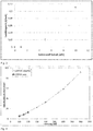
- FIG 2 is an example of a phase determination by means of X-ray diffraction (XRD) of a conductive target material according to the invention (JCPDS cards used: Li 3 PO 4 : 00-015-0760; carbon (graphite) 00-023-0064; Li 2 CO 3 : 00-022-1141 ) shown.
- XRD X-ray diffraction
- a conductive target material according to the invention there are therefore at least two components (phases) which can be distinguished from one another.
- the majority of the microstructure consists of lithium phosphate, which appears as homogeneous, flat areas when viewed in a microscope.
- Elemental carbon is arranged in a network-like manner around these two-dimensional areas, a preferably coherent formation of the carbon being referred to here as a network.
- the extent to which this network develops during the manufacturing process can be influenced by the choice of grain sizes of the starting powder used and the mixing process carried out.
- the content (for example in at%) of added carbon in combination with the grain sizes of the starting powder used has an influence on the formation of the network and the spatial - and thus visible two-dimensional - expansion of the areas formed of lithium phosphate areas and carbon Areas.
- the carbon content remains the same, the formation of a network is made more difficult, the smaller the grain size of the starting powder, the lithium phosphate, is selected.
- the microstructure of a conductive target material according to the invention is usually analyzed using two-dimensional sections through the three-dimensional target material.
- the three-dimensional microstructure of a conductive target material according to the invention is essentially isotropic, that is, there are no or essentially no differences in the microstructure in relation to the plane of observation or no directional dependency of the material properties.
- a conductive target material according to the invention preferably has an area fraction of carbon between 3 and 20%, measured on a cut surface of the target material.
- a metallographic section is produced and examined with a light or electron microscope.
- image evaluation software surface analyzes can be carried out on microscopic images generated in this way. This is done using an image analysis to determine individual phase components of the structure mentioned, typically by contrasting the phases to be distinguished.
- an area fraction of carbon of 5 to 15% measured on a cut surface of the conductive target material according to the invention.
- the combinations of properties that can be achieved are particularly advantageous and a particularly high output and separation rate can be achieved. In particular, this is ensured by heat dissipation during the sputtering process which is optimized in this preferred range of the measured area proportion of carbon.
- a conductive target material according to the invention preferably contains between 3 and 20 at% carbon.
- the carbon content in at% of a conductive target material according to the invention is set by converting it into wt% and weighing in the corresponding amounts of powder. On the finished target material, the carbon content in at% can be checked or verified using hot gas extraction (also: combustion analysis). The carbon contained is burned at temperatures of ⁇ 1600 ° C in an aluminum oxide crucible in a stream of oxygen and determined in the form of its oxides using an infrared cell.
- Carbon contents of 5 to 15 at% in the conductive target material according to the invention are further preferred. From a content of about 5 at%, the electrical conductivity achieved is already so high that a 5 to 10-fold increase in the deposition rate can be achieved. With additional optimization of the A further increase in the achievable deposition rates can also be possible during the sputtering process.
- the thermal conductivity (also referred to as thermal conductivity) of the powder mixture is set during the production of a conductive target material according to the invention and thus better compactability is achieved.
- the electrical conductivity of a conductive target material according to the invention is preferably at least 0.01 S / mm.
- An electrical conductivity of preferably at least 0.01 S / mm ensures that the target material can be deposited using a DC or pulsed DC sputtering process.
- Deposition rates can be achieved that are 5 to 10 times those achieved in RF sputtering processes. The times required for the deposition of a lithium-ion electrolyte layer with a certain required thickness can thereby be greatly reduced and the costs incurred can thus be drastically reduced.
- an electrical conductivity of the conductive target material according to the invention of at least 0.02 S / mm.
- the electrical conductivity can easily be determined with commercially available devices by means of transport measurement, for example a four-point measurement, and describes the ability of a material to conduct electrical current.
- the thermal diffusivity of a conductive target material according to the invention is preferably at least 2.5 mm 2 / s.
- This increased thermal diffusivity of a conductive target material according to the invention compared to pure lithium compounds, for example lithium phosphate (Li 3 PO 4 ), enables higher power input during the sputtering process, since the temperature that arises in the target material can be dissipated more quickly and the temperature that is established in the target material is reduced becomes.
- pure lithium compounds for example lithium phosphate (Li 3 PO 4 )
- a thermal diffusivity of a conductive target material according to the invention of at least 3 mm 2 / s is also preferred, since this allows the power input into the target material to be increased even further.
- These values for the thermal diffusivity apply to room temperature. Typically, the thermal diffusivity decreases with increasing temperature. However, it is further advantageous if, even at typical application temperatures of a conductive target material according to the invention between approximately 100 and 250 ° C., the thermal conductivity of the same is at least 1.5 mm 2 / s.
- the thermal diffusivity can easily be determined using the laser flash method and is the property of a certain material that describes the temporal change in the spatial distribution of temperature due to thermal conduction as a result of a temperature gradient.
- a conductive target material according to the invention preferably has a coefficient of thermal expansion of between 10 to 20 ppm / K.
- the increased coefficient of thermal expansion of a conductive taret material according to the invention is adapted to that of typical materials for Support elements, for example a back plate made of copper (thermal expansion coefficient of copper about 16 ppm / K).
- This adaptation of the thermal expansion coefficient ensures increased thermal shock resistance and thermal shock resistance of the target material during use.
- flaking of the target material after an optional connection to a support element (optional bonding step) is largely avoided.
- the coefficient of thermal expansion of a target material according to the invention can easily be determined by means of dilatometer measurement.
- Another advantage of the optimized thermal properties of a target material according to the invention is the use of higher melting solder materials such as Sn for a connection (optional bonding step) with a support element, which is made possible by this. As a result, the power input during the sputtering process can be increased even further.
- the relative density of a conductive target material according to the invention is preferably at least 95%. A relative density of at least 99% is further preferred. The higher the relative density of the conductive target material, the more advantageous its properties. Target materials with relative densities of less than 95% have a porous structure that can act as a virtual leak as well as a source of contamination. In addition, target materials with a relative density that is too low tend to absorb water and other impurities, which can subsequently lead to a deposition process that is more difficult to control.
- the relative density can easily be determined using the Archimedean principle using buoyancy methods.
- the mechanical strength of a conductive target material according to the invention is preferably sufficiently high to ensure possible mechanical processing in the course of the manufacturing process.
- a conductive target material according to the invention is preferably intended for use in depositing a lithium-ion electrolyte layer for a thin-film battery.
- a lithium-ion electrolyte layer for a thin-film battery in different production systems and for different geometries of the substrates to be coated places different geometric requirements on a conductive target material according to the invention. Accordingly, it can be in the form of a plate, a disk, a rod, a tube or another complex-shaped three-dimensional body. Such a complex-shaped body can, for example, have the shape of a pot or a hollow cathode.
- the lithium-ion electrolyte layers deposited with a target material according to the invention should have only a very low electrical conductivity or should preferably be electrically insulating. The suitability of such a layer as an electrolyte results from its ionic conductivity. Accordingly, the carbon contained in a conductive target material according to the invention must not, or essentially not, be incorporated into the deposited layer. The carbon contained is preferably bound by the oxygen contained in residual gases in the sputtering atmosphere in the form of CO or CO 2 and then pumped out. The carbon content in the deposited layer can be reduced even further, for example by means of an optional reactive sputtering step. As a result, the function of the lithium-ion electrolyte layers deposited with a target material according to the invention is not impaired by the carbon contained in the target material.
- a powder mixture for a conductive target material according to the invention is produced by weighing in the required amounts of powder and mixing in a suitable mixing unit until a homogeneous distribution of the components in the powder mixture is ensured.
- the powder mixture produced in this way is filled into a mold which, according to the subsequent compression step, can have different three-dimensional dimensions and can be made of different materials.
- Typical materials for such shapes are, for example, graphite, CFC (carbon fiber reinforced carbons), Mo or TZM (titanium-zirconium-molybdenum).
- the powder mixture filled in a mold is then compacted; the compacting step can be carried out either by pressure, by temperature or by pressure and temperature.
- Suitable methods for the densification step are, for example, hot pressing and spark plasma sintering (SPS), but other densification methods are also possible.
- SPS spark plasma sintering
- the powder used which is essentially a lithium compound, preferably the lithium phosphate powder
- the powder used which is essentially a lithium compound, preferably the lithium phosphate powder
- water of crystallization contained in commercially available powder is broken down, and thus the oxygen content of the powder and, subsequently, the Powder mixture is reduced.
- the optimum temperature required for the drying step can be optimized, for example, by performing a thermogravimetric measurement.
- mechanical processing of the blank obtained may be necessary.
- Such a machining step should preferably be carried out dry, since an at least superficial attack on the blank could take place in the case of wet machining.
- mechanical processing for For example, by turning, milling or grinding, both the final geometry of the conductive target material can be set or made more precise, and, for example, a certain desired roughness of the surface of the same can be set.
- Such mechanical processing can, as already described, be carried out after the powder mixture has been compacted to form a blank, as well as after an optional bonding step and as a final processing.
- a conductive target material according to the invention can furthermore be connected to one or more corresponding support elements, for example a back plate or a support tube, by a bonding step.
- Such support elements can be made of Cu, Cu alloys, Ti or Ti alloys, for example. However, other materials can also be used for the production of corresponding support elements. Elements or alloys with a low melting point, for example indium, are preferably used for such a bonding step.
- an adhesion promoter for example WNi, can optionally be used to ensure better wetting.
- the compression step in a method for producing a conductive target material according to the invention is preferably carried out via hot pressing (HP) or spark plasma sintering (SPS).
- HP hot pressing
- SPS spark plasma sintering
- other compression methods such as hot isostatic pressing (HIP) or cold isostatic pressing (CIP) and subsequent sintering are also possible.
- the powder mixture filled in a corresponding mold is compressed by means of pressure and temperature, with heating to the sintering temperature taking place directly in the mold through the introduction of electrical current.
- Advantages of using SPS for the compaction step are a drastic reduction in the necessary sintering time, as well as the fact that no green compact produced before sintering is required.
- a conductive target material according to the invention is preferably densified by means of SPS at temperatures between 700 and 900 ° C. However, this does not rule out compaction at temperatures below or above the specified range.
- a target material according to the invention is preferably compressed by means of SPS at pressures between 10 and 60 bar. However, this does not exclude compression at pressures below or above the specified range.
- the powder mixture filled into the mold is compressed by means of pressure and temperature, with heating to the sintering temperature taking place using a heated mold, for example a graphite mold.
- compression by means of HP of a conductive target material according to the invention takes place between 700 and 900 ° C.
- this does not rule out compaction at temperatures below or above the specified range.
- a target material according to the invention is preferably compressed by means of HP at pressures between 10 and 60 bar. However, this does not exclude compression at pressures below or above the specified range.
- the time required for compaction depends on the dimensions of the conductive target material produced in each case and can easily be determined by optimizing the cycle in the course of implementing the compaction process.
- the powder mixture thus obtained was filled into the graphite mold of a hot press and compacted therein at a temperature of 875 ° C. and a pressing force of about 3 MPa for 2 hours under an Ar atmosphere to form a target material with the dimensions 261 ⁇ 241 mm and 10 mm thick.
- the target material obtained in this way was cleaned by means of sandblasting and then dry-machined to its final geometry.
- a finished target was produced by means of a bonding step on a back plate made of copper.
- the powder mixture obtained in this way was poured into the graphite mold of a Spark Plasma sintering system (SPS) and then under a pressure of 20 bar and at a temperature of 875 ° C., which was held for 1 hour, to give a disk-shaped target material with a diameter of 73.5 mm and compacted to a thickness of 5 mm.
- the target material obtained in this way was then ground by means of a dry processing step and processed to a finished target by means of a bonding step on a copper back plate.
- SPS Spark Plasma sintering system
- a DC sputtering test was carried out under an Ar atmosphere (pressure 7.5 * 10 -3 mbar) to determine the deposition rate ) carried out with a power input of 10 W / cm 2 target material.
- a layer thickness of 1.5 ⁇ m was achieved in a time of 990 s.
- a measurement of the electrical conductivity of this layer by means of four-point measurement did not reveal any measurable conductivity.
Landscapes
- Engineering & Computer Science (AREA)
- Chemical & Material Sciences (AREA)
- Manufacturing & Machinery (AREA)
- Mechanical Engineering (AREA)
- Ceramic Engineering (AREA)
- Materials Engineering (AREA)
- Organic Chemistry (AREA)
- Chemical Kinetics & Catalysis (AREA)
- General Engineering & Computer Science (AREA)
- Structural Engineering (AREA)
- Combustion & Propulsion (AREA)
- General Chemical & Material Sciences (AREA)
- Electrochemistry (AREA)
- Metallurgy (AREA)
- Physics & Mathematics (AREA)
- Inorganic Chemistry (AREA)
- Condensed Matter Physics & Semiconductors (AREA)
- General Physics & Mathematics (AREA)
- Plasma & Fusion (AREA)
- Analytical Chemistry (AREA)
- Secondary Cells (AREA)
- Physical Vapour Deposition (AREA)
- Compositions Of Oxide Ceramics (AREA)
- Conductive Materials (AREA)
Applications Claiming Priority (2)
| Application Number | Priority Date | Filing Date | Title |
|---|---|---|---|
| AT2882013 | 2013-09-05 | ||
| PCT/AT2014/000166 WO2015031920A1 (de) | 2013-09-05 | 2014-09-03 | Leitfähiges targetmaterial |
Publications (2)
| Publication Number | Publication Date |
|---|---|
| EP3041809A1 EP3041809A1 (de) | 2016-07-13 |
| EP3041809B1 true EP3041809B1 (de) | 2021-03-03 |
Family
ID=52627596
Family Applications (1)
| Application Number | Title | Priority Date | Filing Date |
|---|---|---|---|
| EP14789129.5A Active EP3041809B1 (de) | 2013-09-05 | 2014-09-03 | Leitfähiges targetmaterial |
Country Status (7)
Families Citing this family (9)
| Publication number | Priority date | Publication date | Assignee | Title |
|---|---|---|---|---|
| DE102014105531A1 (de) * | 2014-04-17 | 2015-10-22 | Schmid Energy Systems Gmbh | LiPON oder LiPSON Festelektrolyt-Schichten und Verfahren zur Herstellung solcher Schichten |
| CN106058305B (zh) * | 2016-08-12 | 2019-02-05 | 合肥国轩高科动力能源有限公司 | 一种用pld原位制备微型全固态薄膜锂离子电池的方法 |
| JP6627708B2 (ja) * | 2016-10-07 | 2020-01-08 | トヨタ自動車株式会社 | リチウムイオン二次電池、及び、リチウムイオン二次電池の製造方法 |
| JP6982779B2 (ja) * | 2017-04-25 | 2021-12-17 | トヨタ自動車株式会社 | 非水系二次電池の製造方法 |
| CN109553409A (zh) * | 2018-12-28 | 2019-04-02 | 有研工程技术研究院有限公司 | 一种固态电解质薄膜用Li3PO4靶材的制备方法和应用 |
| CN114094055A (zh) * | 2021-11-11 | 2022-02-25 | 杭州电子科技大学 | 一种磷化锂电极的制备方法 |
| CN114242947A (zh) * | 2021-12-22 | 2022-03-25 | 杭州电子科技大学 | 一种碳包覆磷化锂电极及其制备方法 |
| CN114314537B (zh) * | 2021-12-30 | 2023-08-15 | 杭州电子科技大学 | 一种磷化锂基复合材料的制备方法及其作为补锂材料的应用 |
| BE1030855B1 (nl) | 2022-09-09 | 2024-04-08 | Soleras Advanced Coatings Bv | Geleidend sputterdoel en methode om daarmee een laag af te zetten |
Citations (1)
| Publication number | Priority date | Publication date | Assignee | Title |
|---|---|---|---|---|
| KR20030043177A (ko) * | 2001-11-27 | 2003-06-02 | 일진나노텍 주식회사 | 탄소 나노튜브를 이용하는 마이크로 전지 및 이를제조하는 방법 |
Family Cites Families (17)
| Publication number | Priority date | Publication date | Assignee | Title |
|---|---|---|---|---|
| GB1314884A (en) | 1970-05-28 | 1973-04-26 | Mullard Ltd | Manufacturing target electrodes for x-ray tubes |
| JPS583966B2 (ja) * | 1979-10-29 | 1983-01-24 | 日本黒鉛工業株式会社 | 高温パッキング用黒鉛圧縮成形体の製造方法 |
| JP2004234977A (ja) * | 2003-01-29 | 2004-08-19 | Matsushita Electric Ind Co Ltd | リチウム二次電池用正極材料およびその製造方法ならびにそれを用いたリチウム二次電池 |
| JP4641375B2 (ja) * | 2003-10-20 | 2011-03-02 | 日立マクセル株式会社 | オリビン型リン酸リチウムと炭素材料との複合体の製造方法 |
| KR20080071973A (ko) | 2005-10-13 | 2008-08-05 | 엔.브이. 베카에르트 에스.에이. | 스퍼터링에 의한 코팅 증착법 |
| US8197781B2 (en) | 2006-11-07 | 2012-06-12 | Infinite Power Solutions, Inc. | Sputtering target of Li3PO4 and method for producing same |
| WO2009014394A2 (en) | 2007-07-25 | 2009-01-29 | Nuricell, Inc. | Method for depositing ceramic thin film by sputtering using non-conductive target |
| US8784512B2 (en) | 2007-08-13 | 2014-07-22 | University Of Virginia Patent Foundation | Thin film battery synthesis by directed vapor deposition |
| WO2009086038A1 (en) * | 2007-12-21 | 2009-07-09 | Infinite Power Solutions, Inc. | Method for sputter targets for electrolyte films |
| EP2135973A1 (en) | 2008-06-18 | 2009-12-23 | Centre National de la Recherche Scientifique | Method for the manufacturing of sputtering targets using an inorganic polymer |
| TWI440597B (zh) * | 2008-08-26 | 2014-06-11 | Basf Se | 於水熱條件下合成LiFePO4 |
| EP2228855B1 (en) * | 2009-03-12 | 2014-02-26 | Belenos Clean Power Holding AG | Open porous electrically conductive nanocomposite material |
| JP5484928B2 (ja) | 2010-01-19 | 2014-05-07 | 株式会社オハラ | 全固体電池 |
| CN102206802B (zh) | 2010-03-29 | 2012-12-19 | 苏州晶纯新材料有限公司 | 全固态薄膜锂离子电池相关靶材及其制造方法 |
| KR101130302B1 (ko) | 2010-08-26 | 2012-03-22 | 한국기계연구원 | 스파크 플라즈마 소결에 의한 세라믹 분말 대량 합성용 금형 |
| JP2013122080A (ja) | 2011-12-12 | 2013-06-20 | Ulvac Japan Ltd | スパッタリング装置 |
| CN103401016B (zh) * | 2013-08-05 | 2015-08-19 | 宁德时代新能源科技有限公司 | 高能量密度锂离子电池 |
-
2014
- 2014-08-05 TW TW103126722A patent/TWI611032B/zh active
- 2014-09-03 US US14/917,094 patent/US11081325B2/en active Active
- 2014-09-03 WO PCT/AT2014/000166 patent/WO2015031920A1/de active Application Filing
- 2014-09-03 JP JP2016539356A patent/JP6657094B2/ja active Active
- 2014-09-03 CN CN201480048869.1A patent/CN105579419B/zh active Active
- 2014-09-03 KR KR1020167005811A patent/KR20160051772A/ko not_active Ceased
- 2014-09-03 KR KR1020217021416A patent/KR102389964B1/ko active Active
- 2014-09-03 EP EP14789129.5A patent/EP3041809B1/de active Active
Patent Citations (1)
| Publication number | Priority date | Publication date | Assignee | Title |
|---|---|---|---|---|
| KR20030043177A (ko) * | 2001-11-27 | 2003-06-02 | 일진나노텍 주식회사 | 탄소 나노튜브를 이용하는 마이크로 전지 및 이를제조하는 방법 |
Also Published As
| Publication number | Publication date |
|---|---|
| KR20160051772A (ko) | 2016-05-11 |
| JP2016536463A (ja) | 2016-11-24 |
| US11081325B2 (en) | 2021-08-03 |
| TW201510248A (zh) | 2015-03-16 |
| KR102389964B1 (ko) | 2022-04-22 |
| CN105579419A (zh) | 2016-05-11 |
| KR20210089271A (ko) | 2021-07-15 |
| US20160217984A1 (en) | 2016-07-28 |
| TWI611032B (zh) | 2018-01-11 |
| EP3041809A1 (de) | 2016-07-13 |
| JP6657094B2 (ja) | 2020-03-04 |
| WO2015031920A1 (de) | 2015-03-12 |
| CN105579419B (zh) | 2020-07-03 |
Similar Documents
| Publication | Publication Date | Title |
|---|---|---|
| EP3041809B1 (de) | Leitfähiges targetmaterial | |
| DE102018109462B4 (de) | Verfahren zur Behandlung einer Oberfläche eines festen Glas-, Glaskeramik- oder einesKeramik-Elektrolytkörpers und Verfahren zur Behandlung einer Oberfläche eines festenGlas- oder Glaskeramik-Elektrolytkörpers | |
| EP3084517B1 (de) | W-ni-sputtertarget | |
| EP2093825B1 (en) | Battery structure and lithium secondary battery using the same | |
| KR102030892B1 (ko) | Ito 스퍼터링 타겟 및 그 제조 방법 그리고 ito 투명 도전막 및 ito 투명 도전막의 제조 방법 | |
| EP2792007A1 (de) | Festkörperelektrolyt für den einsatz in lithium-luft- oder lithium-wasser-akkumulatoren | |
| DE102012217191A1 (de) | Herstellen eines Refraktärmetall-Bauteils | |
| WO2014117190A1 (de) | Cu-ga-in-na target | |
| WO2015158607A1 (de) | Lipon oder lipson festelektrolyt-schichten und verfahren zur herstellung solcher schichten | |
| JP2002302761A (ja) | Itoスパッタリングターゲットおよびその製造方法 | |
| WO2015042622A1 (de) | Kupfer-gallium sputtering target | |
| Camara et al. | Effect of low environmental pressure on sintering behavior of NASICON-type Li1. 3Al0. 3Ti1. 7 (PO4) 3 solid electrolytes: An in situ ESEM study | |
| Acord et al. | Manipulating ionic conductivity through chemical modifications in solid-state electrolytes prepared with binderless laser powder bed fusion processing | |
| Tanaka et al. | Analysis of Liquid Phase Sintering of Metal-Glass Mixed Powder by Experiment and Computer Simulation | |
| WO2015091259A1 (de) | Verfahren zur herstellung wenigstens einer energiespeicherkomponente für einen elektrischen energiespeicher | |
| EP3647456B1 (de) | Kathode und ein verfahren zur herstellung einer kathode | |
| WO2025087588A1 (de) | Verfahren zur herstellung eines vorproduktes, einer batteriezelle und einer batterie | |
| WO2024165268A1 (de) | Siliziumhaltige übergangsmetallboridverdampfungsquelle | |
| DE102024200773A1 (de) | Verfahren und System zum Sintern eines keramischen Bauteils | |
| Gündüz | Microstructure-property relation in Li1. 3Al0. 3Ti1. 7 (PO4) 3 superionic Li-conducting ceramics | |
| WO2012146347A2 (de) | Festkörper, verfahren zu seiner herstellung und seine verwendung | |
| DE102012203055B4 (de) | Sputtertarget aus einem galliumdotiertes Zink enthaltenden Material und Verfahren zu dessen Herstellung | |
| DE102020209708A1 (de) | Sinterhilfsmittelmischung, Festkörperionenleiter und Verfahren zum Herstellen von Festkörperionenleitern | |
| DE102022108265A1 (de) | Verfahren zur herstellung dreidimensionaler festelektrolytstrukturen | |
| DE102019203820A1 (de) | Lithiummetall-Elektrode und Verfahren zu deren Herstellung |
Legal Events
| Date | Code | Title | Description |
|---|---|---|---|
| PUAI | Public reference made under article 153(3) epc to a published international application that has entered the european phase |
Free format text: ORIGINAL CODE: 0009012 |
|
| 17P | Request for examination filed |
Effective date: 20160217 |
|
| AK | Designated contracting states |
Kind code of ref document: A1 Designated state(s): AL AT BE BG CH CY CZ DE DK EE ES FI FR GB GR HR HU IE IS IT LI LT LU LV MC MK MT NL NO PL PT RO RS SE SI SK SM TR |
|
| AX | Request for extension of the european patent |
Extension state: BA ME |
|
| DAX | Request for extension of the european patent (deleted) | ||
| STAA | Information on the status of an ep patent application or granted ep patent |
Free format text: STATUS: EXAMINATION IS IN PROGRESS |
|
| 17Q | First examination report despatched |
Effective date: 20180604 |
|
| RIC1 | Information provided on ipc code assigned before grant |
Ipc: H01J 37/34 20060101ALI20200724BHEP Ipc: C04B 35/52 20060101ALI20200724BHEP Ipc: C04B 35/01 20060101ALI20200724BHEP Ipc: C01B 25/30 20060101ALI20200724BHEP Ipc: H01M 10/0562 20100101ALI20200724BHEP Ipc: C04B 35/447 20060101AFI20200724BHEP Ipc: H01M 10/052 20100101ALI20200724BHEP Ipc: C23C 14/34 20060101ALI20200724BHEP Ipc: C04B 35/645 20060101ALI20200724BHEP Ipc: H01M 6/18 20060101ALI20200724BHEP Ipc: H01M 6/40 20060101ALI20200724BHEP |
|
| GRAP | Despatch of communication of intention to grant a patent |
Free format text: ORIGINAL CODE: EPIDOSNIGR1 |
|
| STAA | Information on the status of an ep patent application or granted ep patent |
Free format text: STATUS: GRANT OF PATENT IS INTENDED |
|
| INTG | Intention to grant announced |
Effective date: 20200929 |
|
| GRAS | Grant fee paid |
Free format text: ORIGINAL CODE: EPIDOSNIGR3 |
|
| GRAA | (expected) grant |
Free format text: ORIGINAL CODE: 0009210 |
|
| STAA | Information on the status of an ep patent application or granted ep patent |
Free format text: STATUS: THE PATENT HAS BEEN GRANTED |
|
| AK | Designated contracting states |
Kind code of ref document: B1 Designated state(s): AL AT BE BG CH CY CZ DE DK EE ES FI FR GB GR HR HU IE IS IT LI LT LU LV MC MK MT NL NO PL PT RO RS SE SI SK SM TR |
|
| REG | Reference to a national code |
Ref country code: GB Ref legal event code: FG4D Free format text: NOT ENGLISH |
|
| REG | Reference to a national code |
Ref country code: AT Ref legal event code: REF Ref document number: 1367033 Country of ref document: AT Kind code of ref document: T Effective date: 20210315 Ref country code: CH Ref legal event code: EP |
|
| REG | Reference to a national code |
Ref country code: DE Ref legal event code: R096 Ref document number: 502014015341 Country of ref document: DE |
|
| REG | Reference to a national code |
Ref country code: IE Ref legal event code: FG4D Free format text: LANGUAGE OF EP DOCUMENT: GERMAN |
|
| REG | Reference to a national code |
Ref country code: LT Ref legal event code: MG9D |
|
| PG25 | Lapsed in a contracting state [announced via postgrant information from national office to epo] |
Ref country code: LT Free format text: LAPSE BECAUSE OF FAILURE TO SUBMIT A TRANSLATION OF THE DESCRIPTION OR TO PAY THE FEE WITHIN THE PRESCRIBED TIME-LIMIT Effective date: 20210303 Ref country code: FI Free format text: LAPSE BECAUSE OF FAILURE TO SUBMIT A TRANSLATION OF THE DESCRIPTION OR TO PAY THE FEE WITHIN THE PRESCRIBED TIME-LIMIT Effective date: 20210303 Ref country code: HR Free format text: LAPSE BECAUSE OF FAILURE TO SUBMIT A TRANSLATION OF THE DESCRIPTION OR TO PAY THE FEE WITHIN THE PRESCRIBED TIME-LIMIT Effective date: 20210303 Ref country code: GR Free format text: LAPSE BECAUSE OF FAILURE TO SUBMIT A TRANSLATION OF THE DESCRIPTION OR TO PAY THE FEE WITHIN THE PRESCRIBED TIME-LIMIT Effective date: 20210604 Ref country code: BG Free format text: LAPSE BECAUSE OF FAILURE TO SUBMIT A TRANSLATION OF THE DESCRIPTION OR TO PAY THE FEE WITHIN THE PRESCRIBED TIME-LIMIT Effective date: 20210603 Ref country code: NO Free format text: LAPSE BECAUSE OF FAILURE TO SUBMIT A TRANSLATION OF THE DESCRIPTION OR TO PAY THE FEE WITHIN THE PRESCRIBED TIME-LIMIT Effective date: 20210603 |
|
| REG | Reference to a national code |
Ref country code: NL Ref legal event code: MP Effective date: 20210303 |
|
| PG25 | Lapsed in a contracting state [announced via postgrant information from national office to epo] |
Ref country code: PL Free format text: LAPSE BECAUSE OF FAILURE TO SUBMIT A TRANSLATION OF THE DESCRIPTION OR TO PAY THE FEE WITHIN THE PRESCRIBED TIME-LIMIT Effective date: 20210303 Ref country code: RS Free format text: LAPSE BECAUSE OF FAILURE TO SUBMIT A TRANSLATION OF THE DESCRIPTION OR TO PAY THE FEE WITHIN THE PRESCRIBED TIME-LIMIT Effective date: 20210303 Ref country code: LV Free format text: LAPSE BECAUSE OF FAILURE TO SUBMIT A TRANSLATION OF THE DESCRIPTION OR TO PAY THE FEE WITHIN THE PRESCRIBED TIME-LIMIT Effective date: 20210303 Ref country code: SE Free format text: LAPSE BECAUSE OF FAILURE TO SUBMIT A TRANSLATION OF THE DESCRIPTION OR TO PAY THE FEE WITHIN THE PRESCRIBED TIME-LIMIT Effective date: 20210303 |
|
| PG25 | Lapsed in a contracting state [announced via postgrant information from national office to epo] |
Ref country code: NL Free format text: LAPSE BECAUSE OF FAILURE TO SUBMIT A TRANSLATION OF THE DESCRIPTION OR TO PAY THE FEE WITHIN THE PRESCRIBED TIME-LIMIT Effective date: 20210303 |
|
| PG25 | Lapsed in a contracting state [announced via postgrant information from national office to epo] |
Ref country code: CZ Free format text: LAPSE BECAUSE OF FAILURE TO SUBMIT A TRANSLATION OF THE DESCRIPTION OR TO PAY THE FEE WITHIN THE PRESCRIBED TIME-LIMIT Effective date: 20210303 Ref country code: EE Free format text: LAPSE BECAUSE OF FAILURE TO SUBMIT A TRANSLATION OF THE DESCRIPTION OR TO PAY THE FEE WITHIN THE PRESCRIBED TIME-LIMIT Effective date: 20210303 Ref country code: SM Free format text: LAPSE BECAUSE OF FAILURE TO SUBMIT A TRANSLATION OF THE DESCRIPTION OR TO PAY THE FEE WITHIN THE PRESCRIBED TIME-LIMIT Effective date: 20210303 |
|
| PG25 | Lapsed in a contracting state [announced via postgrant information from national office to epo] |
Ref country code: PT Free format text: LAPSE BECAUSE OF FAILURE TO SUBMIT A TRANSLATION OF THE DESCRIPTION OR TO PAY THE FEE WITHIN THE PRESCRIBED TIME-LIMIT Effective date: 20210705 Ref country code: ES Free format text: LAPSE BECAUSE OF FAILURE TO SUBMIT A TRANSLATION OF THE DESCRIPTION OR TO PAY THE FEE WITHIN THE PRESCRIBED TIME-LIMIT Effective date: 20210303 Ref country code: SK Free format text: LAPSE BECAUSE OF FAILURE TO SUBMIT A TRANSLATION OF THE DESCRIPTION OR TO PAY THE FEE WITHIN THE PRESCRIBED TIME-LIMIT Effective date: 20210303 Ref country code: RO Free format text: LAPSE BECAUSE OF FAILURE TO SUBMIT A TRANSLATION OF THE DESCRIPTION OR TO PAY THE FEE WITHIN THE PRESCRIBED TIME-LIMIT Effective date: 20210303 Ref country code: IS Free format text: LAPSE BECAUSE OF FAILURE TO SUBMIT A TRANSLATION OF THE DESCRIPTION OR TO PAY THE FEE WITHIN THE PRESCRIBED TIME-LIMIT Effective date: 20210703 |
|
| REG | Reference to a national code |
Ref country code: DE Ref legal event code: R097 Ref document number: 502014015341 Country of ref document: DE |
|
| PLBE | No opposition filed within time limit |
Free format text: ORIGINAL CODE: 0009261 |
|
| STAA | Information on the status of an ep patent application or granted ep patent |
Free format text: STATUS: NO OPPOSITION FILED WITHIN TIME LIMIT |
|
| PG25 | Lapsed in a contracting state [announced via postgrant information from national office to epo] |
Ref country code: AL Free format text: LAPSE BECAUSE OF FAILURE TO SUBMIT A TRANSLATION OF THE DESCRIPTION OR TO PAY THE FEE WITHIN THE PRESCRIBED TIME-LIMIT Effective date: 20210303 Ref country code: DK Free format text: LAPSE BECAUSE OF FAILURE TO SUBMIT A TRANSLATION OF THE DESCRIPTION OR TO PAY THE FEE WITHIN THE PRESCRIBED TIME-LIMIT Effective date: 20210303 |
|
| 26N | No opposition filed |
Effective date: 20211206 |
|
| PG25 | Lapsed in a contracting state [announced via postgrant information from national office to epo] |
Ref country code: SI Free format text: LAPSE BECAUSE OF FAILURE TO SUBMIT A TRANSLATION OF THE DESCRIPTION OR TO PAY THE FEE WITHIN THE PRESCRIBED TIME-LIMIT Effective date: 20210303 |
|
| PG25 | Lapsed in a contracting state [announced via postgrant information from national office to epo] |
Ref country code: IT Free format text: LAPSE BECAUSE OF FAILURE TO SUBMIT A TRANSLATION OF THE DESCRIPTION OR TO PAY THE FEE WITHIN THE PRESCRIBED TIME-LIMIT Effective date: 20210303 |
|
| REG | Reference to a national code |
Ref country code: CH Ref legal event code: PL |
|
| REG | Reference to a national code |
Ref country code: BE Ref legal event code: MM Effective date: 20210930 |
|
| GBPC | Gb: european patent ceased through non-payment of renewal fee |
Effective date: 20210903 |
|
| PG25 | Lapsed in a contracting state [announced via postgrant information from national office to epo] |
Ref country code: IS Free format text: LAPSE BECAUSE OF FAILURE TO SUBMIT A TRANSLATION OF THE DESCRIPTION OR TO PAY THE FEE WITHIN THE PRESCRIBED TIME-LIMIT Effective date: 20210703 Ref country code: MC Free format text: LAPSE BECAUSE OF FAILURE TO SUBMIT A TRANSLATION OF THE DESCRIPTION OR TO PAY THE FEE WITHIN THE PRESCRIBED TIME-LIMIT Effective date: 20210303 |
|
| PG25 | Lapsed in a contracting state [announced via postgrant information from national office to epo] |
Ref country code: LU Free format text: LAPSE BECAUSE OF NON-PAYMENT OF DUE FEES Effective date: 20210903 Ref country code: IE Free format text: LAPSE BECAUSE OF NON-PAYMENT OF DUE FEES Effective date: 20210903 Ref country code: GB Free format text: LAPSE BECAUSE OF NON-PAYMENT OF DUE FEES Effective date: 20210903 Ref country code: FR Free format text: LAPSE BECAUSE OF NON-PAYMENT OF DUE FEES Effective date: 20210930 Ref country code: BE Free format text: LAPSE BECAUSE OF NON-PAYMENT OF DUE FEES Effective date: 20210930 |
|
| PG25 | Lapsed in a contracting state [announced via postgrant information from national office to epo] |
Ref country code: LI Free format text: LAPSE BECAUSE OF NON-PAYMENT OF DUE FEES Effective date: 20210930 Ref country code: CH Free format text: LAPSE BECAUSE OF NON-PAYMENT OF DUE FEES Effective date: 20210930 |
|
| REG | Reference to a national code |
Ref country code: AT Ref legal event code: MM01 Ref document number: 1367033 Country of ref document: AT Kind code of ref document: T Effective date: 20210903 |
|
| PG25 | Lapsed in a contracting state [announced via postgrant information from national office to epo] |
Ref country code: AT Free format text: LAPSE BECAUSE OF NON-PAYMENT OF DUE FEES Effective date: 20210903 |
|
| PG25 | Lapsed in a contracting state [announced via postgrant information from national office to epo] |
Ref country code: HU Free format text: LAPSE BECAUSE OF FAILURE TO SUBMIT A TRANSLATION OF THE DESCRIPTION OR TO PAY THE FEE WITHIN THE PRESCRIBED TIME-LIMIT; INVALID AB INITIO Effective date: 20140903 |
|
| PG25 | Lapsed in a contracting state [announced via postgrant information from national office to epo] |
Ref country code: CY Free format text: LAPSE BECAUSE OF FAILURE TO SUBMIT A TRANSLATION OF THE DESCRIPTION OR TO PAY THE FEE WITHIN THE PRESCRIBED TIME-LIMIT Effective date: 20210303 |
|
| PG25 | Lapsed in a contracting state [announced via postgrant information from national office to epo] |
Ref country code: MK Free format text: LAPSE BECAUSE OF FAILURE TO SUBMIT A TRANSLATION OF THE DESCRIPTION OR TO PAY THE FEE WITHIN THE PRESCRIBED TIME-LIMIT Effective date: 20210303 |
|
| PG25 | Lapsed in a contracting state [announced via postgrant information from national office to epo] |
Ref country code: TR Free format text: LAPSE BECAUSE OF FAILURE TO SUBMIT A TRANSLATION OF THE DESCRIPTION OR TO PAY THE FEE WITHIN THE PRESCRIBED TIME-LIMIT Effective date: 20210303 |
|
| PG25 | Lapsed in a contracting state [announced via postgrant information from national office to epo] |
Ref country code: MT Free format text: LAPSE BECAUSE OF FAILURE TO SUBMIT A TRANSLATION OF THE DESCRIPTION OR TO PAY THE FEE WITHIN THE PRESCRIBED TIME-LIMIT Effective date: 20210303 |
|
| PGFP | Annual fee paid to national office [announced via postgrant information from national office to epo] |
Ref country code: DE Payment date: 20240918 Year of fee payment: 11 |