EP3037745A1 - Dispositif source de chaleur et procédé de commande de celui-ci - Google Patents
Dispositif source de chaleur et procédé de commande de celui-ci Download PDFInfo
- Publication number
- EP3037745A1 EP3037745A1 EP14863022.1A EP14863022A EP3037745A1 EP 3037745 A1 EP3037745 A1 EP 3037745A1 EP 14863022 A EP14863022 A EP 14863022A EP 3037745 A1 EP3037745 A1 EP 3037745A1
- Authority
- EP
- European Patent Office
- Prior art keywords
- heat
- heat source
- temperature
- heat medium
- source machine
- Prior art date
- Legal status (The legal status is an assumption and is not a legal conclusion. Google has not performed a legal analysis and makes no representation as to the accuracy of the status listed.)
- Granted
Links
- 238000000034 method Methods 0.000 title claims description 26
- 239000003507 refrigerant Substances 0.000 claims description 59
- 230000005494 condensation Effects 0.000 claims description 35
- 238000009833 condensation Methods 0.000 claims description 35
- 238000011156 evaluation Methods 0.000 claims description 18
- XLYOFNOQVPJJNP-UHFFFAOYSA-N water Substances O XLYOFNOQVPJJNP-UHFFFAOYSA-N 0.000 abstract description 93
- 230000007423 decrease Effects 0.000 abstract description 10
- 230000003247 decreasing effect Effects 0.000 abstract description 5
- 238000012546 transfer Methods 0.000 abstract description 3
- 230000004075 alteration Effects 0.000 abstract 2
- 239000000498 cooling water Substances 0.000 description 17
- 238000010586 diagram Methods 0.000 description 11
- 238000001816 cooling Methods 0.000 description 10
- 230000006870 function Effects 0.000 description 10
- ATJFFYVFTNAWJD-UHFFFAOYSA-N Tin Chemical compound [Sn] ATJFFYVFTNAWJD-UHFFFAOYSA-N 0.000 description 6
- 238000010438 heat treatment Methods 0.000 description 4
- 238000005259 measurement Methods 0.000 description 4
- 239000000243 solution Substances 0.000 description 4
- 230000002528 anti-freeze Effects 0.000 description 3
- 230000000694 effects Effects 0.000 description 3
- 239000007788 liquid Substances 0.000 description 3
- 238000005057 refrigeration Methods 0.000 description 3
- 238000004378 air conditioning Methods 0.000 description 2
- 238000013461 design Methods 0.000 description 2
- 238000001514 detection method Methods 0.000 description 2
- 238000013459 approach Methods 0.000 description 1
- 239000012267 brine Substances 0.000 description 1
- 238000004891 communication Methods 0.000 description 1
- 238000001704 evaporation Methods 0.000 description 1
- 230000008020 evaporation Effects 0.000 description 1
- 238000009434 installation Methods 0.000 description 1
- 230000003287 optical effect Effects 0.000 description 1
- 238000012545 processing Methods 0.000 description 1
- 238000011084 recovery Methods 0.000 description 1
- 230000000630 rising effect Effects 0.000 description 1
- 238000005070 sampling Methods 0.000 description 1
- 239000004065 semiconductor Substances 0.000 description 1
- HPALAKNZSZLMCH-UHFFFAOYSA-M sodium;chloride;hydrate Chemical compound O.[Na+].[Cl-] HPALAKNZSZLMCH-UHFFFAOYSA-M 0.000 description 1
- 238000004781 supercooling Methods 0.000 description 1
- 238000011144 upstream manufacturing Methods 0.000 description 1
Images


Classifications
-
- F—MECHANICAL ENGINEERING; LIGHTING; HEATING; WEAPONS; BLASTING
- F25—REFRIGERATION OR COOLING; COMBINED HEATING AND REFRIGERATION SYSTEMS; HEAT PUMP SYSTEMS; MANUFACTURE OR STORAGE OF ICE; LIQUEFACTION SOLIDIFICATION OF GASES
- F25D—REFRIGERATORS; COLD ROOMS; ICE-BOXES; COOLING OR FREEZING APPARATUS NOT OTHERWISE PROVIDED FOR
- F25D17/00—Arrangements for circulating cooling fluids; Arrangements for circulating gas, e.g. air, within refrigerated spaces
- F25D17/02—Arrangements for circulating cooling fluids; Arrangements for circulating gas, e.g. air, within refrigerated spaces for circulating liquids, e.g. brine
-
- F—MECHANICAL ENGINEERING; LIGHTING; HEATING; WEAPONS; BLASTING
- F25—REFRIGERATION OR COOLING; COMBINED HEATING AND REFRIGERATION SYSTEMS; HEAT PUMP SYSTEMS; MANUFACTURE OR STORAGE OF ICE; LIQUEFACTION SOLIDIFICATION OF GASES
- F25B—REFRIGERATION MACHINES, PLANTS OR SYSTEMS; COMBINED HEATING AND REFRIGERATION SYSTEMS; HEAT PUMP SYSTEMS
- F25B25/00—Machines, plants or systems, using a combination of modes of operation covered by two or more of the groups F25B1/00 - F25B23/00
- F25B25/005—Machines, plants or systems, using a combination of modes of operation covered by two or more of the groups F25B1/00 - F25B23/00 using primary and secondary systems
-
- F—MECHANICAL ENGINEERING; LIGHTING; HEATING; WEAPONS; BLASTING
- F24—HEATING; RANGES; VENTILATING
- F24F—AIR-CONDITIONING; AIR-HUMIDIFICATION; VENTILATION; USE OF AIR CURRENTS FOR SCREENING
- F24F11/00—Control or safety arrangements
- F24F11/70—Control systems characterised by their outputs; Constructional details thereof
- F24F11/80—Control systems characterised by their outputs; Constructional details thereof for controlling the temperature of the supplied air
- F24F11/83—Control systems characterised by their outputs; Constructional details thereof for controlling the temperature of the supplied air by controlling the supply of heat-exchange fluids to heat-exchangers
- F24F11/84—Control systems characterised by their outputs; Constructional details thereof for controlling the temperature of the supplied air by controlling the supply of heat-exchange fluids to heat-exchangers using valves
-
- F—MECHANICAL ENGINEERING; LIGHTING; HEATING; WEAPONS; BLASTING
- F24—HEATING; RANGES; VENTILATING
- F24F—AIR-CONDITIONING; AIR-HUMIDIFICATION; VENTILATION; USE OF AIR CURRENTS FOR SCREENING
- F24F11/00—Control or safety arrangements
- F24F11/70—Control systems characterised by their outputs; Constructional details thereof
- F24F11/80—Control systems characterised by their outputs; Constructional details thereof for controlling the temperature of the supplied air
- F24F11/83—Control systems characterised by their outputs; Constructional details thereof for controlling the temperature of the supplied air by controlling the supply of heat-exchange fluids to heat-exchangers
- F24F11/85—Control systems characterised by their outputs; Constructional details thereof for controlling the temperature of the supplied air by controlling the supply of heat-exchange fluids to heat-exchangers using variable-flow pumps
-
- F—MECHANICAL ENGINEERING; LIGHTING; HEATING; WEAPONS; BLASTING
- F25—REFRIGERATION OR COOLING; COMBINED HEATING AND REFRIGERATION SYSTEMS; HEAT PUMP SYSTEMS; MANUFACTURE OR STORAGE OF ICE; LIQUEFACTION SOLIDIFICATION OF GASES
- F25B—REFRIGERATION MACHINES, PLANTS OR SYSTEMS; COMBINED HEATING AND REFRIGERATION SYSTEMS; HEAT PUMP SYSTEMS
- F25B41/00—Fluid-circulation arrangements
- F25B41/30—Expansion means; Dispositions thereof
- F25B41/39—Dispositions with two or more expansion means arranged in series, i.e. multi-stage expansion, on a refrigerant line leading to the same evaporator
-
- F—MECHANICAL ENGINEERING; LIGHTING; HEATING; WEAPONS; BLASTING
- F25—REFRIGERATION OR COOLING; COMBINED HEATING AND REFRIGERATION SYSTEMS; HEAT PUMP SYSTEMS; MANUFACTURE OR STORAGE OF ICE; LIQUEFACTION SOLIDIFICATION OF GASES
- F25B—REFRIGERATION MACHINES, PLANTS OR SYSTEMS; COMBINED HEATING AND REFRIGERATION SYSTEMS; HEAT PUMP SYSTEMS
- F25B49/00—Arrangement or mounting of control or safety devices
- F25B49/02—Arrangement or mounting of control or safety devices for compression type machines, plants or systems
-
- F—MECHANICAL ENGINEERING; LIGHTING; HEATING; WEAPONS; BLASTING
- F25—REFRIGERATION OR COOLING; COMBINED HEATING AND REFRIGERATION SYSTEMS; HEAT PUMP SYSTEMS; MANUFACTURE OR STORAGE OF ICE; LIQUEFACTION SOLIDIFICATION OF GASES
- F25D—REFRIGERATORS; COLD ROOMS; ICE-BOXES; COOLING OR FREEZING APPARATUS NOT OTHERWISE PROVIDED FOR
- F25D29/00—Arrangement or mounting of control or safety devices
-
- F—MECHANICAL ENGINEERING; LIGHTING; HEATING; WEAPONS; BLASTING
- F25—REFRIGERATION OR COOLING; COMBINED HEATING AND REFRIGERATION SYSTEMS; HEAT PUMP SYSTEMS; MANUFACTURE OR STORAGE OF ICE; LIQUEFACTION SOLIDIFICATION OF GASES
- F25B—REFRIGERATION MACHINES, PLANTS OR SYSTEMS; COMBINED HEATING AND REFRIGERATION SYSTEMS; HEAT PUMP SYSTEMS
- F25B1/00—Compression machines, plants or systems with non-reversible cycle
- F25B1/04—Compression machines, plants or systems with non-reversible cycle with compressor of rotary type
- F25B1/053—Compression machines, plants or systems with non-reversible cycle with compressor of rotary type of turbine type
-
- F—MECHANICAL ENGINEERING; LIGHTING; HEATING; WEAPONS; BLASTING
- F25—REFRIGERATION OR COOLING; COMBINED HEATING AND REFRIGERATION SYSTEMS; HEAT PUMP SYSTEMS; MANUFACTURE OR STORAGE OF ICE; LIQUEFACTION SOLIDIFICATION OF GASES
- F25B—REFRIGERATION MACHINES, PLANTS OR SYSTEMS; COMBINED HEATING AND REFRIGERATION SYSTEMS; HEAT PUMP SYSTEMS
- F25B2339/00—Details of evaporators; Details of condensers
- F25B2339/04—Details of condensers
- F25B2339/047—Water-cooled condensers
-
- F—MECHANICAL ENGINEERING; LIGHTING; HEATING; WEAPONS; BLASTING
- F25—REFRIGERATION OR COOLING; COMBINED HEATING AND REFRIGERATION SYSTEMS; HEAT PUMP SYSTEMS; MANUFACTURE OR STORAGE OF ICE; LIQUEFACTION SOLIDIFICATION OF GASES
- F25B—REFRIGERATION MACHINES, PLANTS OR SYSTEMS; COMBINED HEATING AND REFRIGERATION SYSTEMS; HEAT PUMP SYSTEMS
- F25B2400/00—General features or devices for refrigeration machines, plants or systems, combined heating and refrigeration systems or heat-pump systems, i.e. not limited to a particular subgroup of F25B
- F25B2400/13—Economisers
-
- F—MECHANICAL ENGINEERING; LIGHTING; HEATING; WEAPONS; BLASTING
- F25—REFRIGERATION OR COOLING; COMBINED HEATING AND REFRIGERATION SYSTEMS; HEAT PUMP SYSTEMS; MANUFACTURE OR STORAGE OF ICE; LIQUEFACTION SOLIDIFICATION OF GASES
- F25B—REFRIGERATION MACHINES, PLANTS OR SYSTEMS; COMBINED HEATING AND REFRIGERATION SYSTEMS; HEAT PUMP SYSTEMS
- F25B2500/00—Problems to be solved
- F25B2500/19—Calculation of parameters
-
- F—MECHANICAL ENGINEERING; LIGHTING; HEATING; WEAPONS; BLASTING
- F25—REFRIGERATION OR COOLING; COMBINED HEATING AND REFRIGERATION SYSTEMS; HEAT PUMP SYSTEMS; MANUFACTURE OR STORAGE OF ICE; LIQUEFACTION SOLIDIFICATION OF GASES
- F25B—REFRIGERATION MACHINES, PLANTS OR SYSTEMS; COMBINED HEATING AND REFRIGERATION SYSTEMS; HEAT PUMP SYSTEMS
- F25B2600/00—Control issues
- F25B2600/02—Compressor control
- F25B2600/021—Inverters therefor
-
- F—MECHANICAL ENGINEERING; LIGHTING; HEATING; WEAPONS; BLASTING
- F25—REFRIGERATION OR COOLING; COMBINED HEATING AND REFRIGERATION SYSTEMS; HEAT PUMP SYSTEMS; MANUFACTURE OR STORAGE OF ICE; LIQUEFACTION SOLIDIFICATION OF GASES
- F25B—REFRIGERATION MACHINES, PLANTS OR SYSTEMS; COMBINED HEATING AND REFRIGERATION SYSTEMS; HEAT PUMP SYSTEMS
- F25B2600/00—Control issues
- F25B2600/02—Compressor control
- F25B2600/026—Compressor control by controlling unloaders
- F25B2600/0261—Compressor control by controlling unloaders external to the compressor
-
- F—MECHANICAL ENGINEERING; LIGHTING; HEATING; WEAPONS; BLASTING
- F25—REFRIGERATION OR COOLING; COMBINED HEATING AND REFRIGERATION SYSTEMS; HEAT PUMP SYSTEMS; MANUFACTURE OR STORAGE OF ICE; LIQUEFACTION SOLIDIFICATION OF GASES
- F25B—REFRIGERATION MACHINES, PLANTS OR SYSTEMS; COMBINED HEATING AND REFRIGERATION SYSTEMS; HEAT PUMP SYSTEMS
- F25B2600/00—Control issues
- F25B2600/02—Compressor control
- F25B2600/027—Compressor control by controlling pressure
- F25B2600/0272—Compressor control by controlling pressure the suction pressure
-
- F—MECHANICAL ENGINEERING; LIGHTING; HEATING; WEAPONS; BLASTING
- F25—REFRIGERATION OR COOLING; COMBINED HEATING AND REFRIGERATION SYSTEMS; HEAT PUMP SYSTEMS; MANUFACTURE OR STORAGE OF ICE; LIQUEFACTION SOLIDIFICATION OF GASES
- F25B—REFRIGERATION MACHINES, PLANTS OR SYSTEMS; COMBINED HEATING AND REFRIGERATION SYSTEMS; HEAT PUMP SYSTEMS
- F25B2700/00—Sensing or detecting of parameters; Sensors therefor
- F25B2700/19—Pressures
- F25B2700/195—Pressures of the condenser
-
- F—MECHANICAL ENGINEERING; LIGHTING; HEATING; WEAPONS; BLASTING
- F25—REFRIGERATION OR COOLING; COMBINED HEATING AND REFRIGERATION SYSTEMS; HEAT PUMP SYSTEMS; MANUFACTURE OR STORAGE OF ICE; LIQUEFACTION SOLIDIFICATION OF GASES
- F25B—REFRIGERATION MACHINES, PLANTS OR SYSTEMS; COMBINED HEATING AND REFRIGERATION SYSTEMS; HEAT PUMP SYSTEMS
- F25B2700/00—Sensing or detecting of parameters; Sensors therefor
- F25B2700/19—Pressures
- F25B2700/197—Pressures of the evaporator
-
- F—MECHANICAL ENGINEERING; LIGHTING; HEATING; WEAPONS; BLASTING
- F25—REFRIGERATION OR COOLING; COMBINED HEATING AND REFRIGERATION SYSTEMS; HEAT PUMP SYSTEMS; MANUFACTURE OR STORAGE OF ICE; LIQUEFACTION SOLIDIFICATION OF GASES
- F25B—REFRIGERATION MACHINES, PLANTS OR SYSTEMS; COMBINED HEATING AND REFRIGERATION SYSTEMS; HEAT PUMP SYSTEMS
- F25B2700/00—Sensing or detecting of parameters; Sensors therefor
- F25B2700/21—Temperatures
- F25B2700/2116—Temperatures of a condenser
- F25B2700/21161—Temperatures of a condenser of the fluid heated by the condenser
-
- F—MECHANICAL ENGINEERING; LIGHTING; HEATING; WEAPONS; BLASTING
- F25—REFRIGERATION OR COOLING; COMBINED HEATING AND REFRIGERATION SYSTEMS; HEAT PUMP SYSTEMS; MANUFACTURE OR STORAGE OF ICE; LIQUEFACTION SOLIDIFICATION OF GASES
- F25B—REFRIGERATION MACHINES, PLANTS OR SYSTEMS; COMBINED HEATING AND REFRIGERATION SYSTEMS; HEAT PUMP SYSTEMS
- F25B2700/00—Sensing or detecting of parameters; Sensors therefor
- F25B2700/21—Temperatures
- F25B2700/2116—Temperatures of a condenser
- F25B2700/21163—Temperatures of a condenser of the refrigerant at the outlet of the condenser
-
- F—MECHANICAL ENGINEERING; LIGHTING; HEATING; WEAPONS; BLASTING
- F25—REFRIGERATION OR COOLING; COMBINED HEATING AND REFRIGERATION SYSTEMS; HEAT PUMP SYSTEMS; MANUFACTURE OR STORAGE OF ICE; LIQUEFACTION SOLIDIFICATION OF GASES
- F25B—REFRIGERATION MACHINES, PLANTS OR SYSTEMS; COMBINED HEATING AND REFRIGERATION SYSTEMS; HEAT PUMP SYSTEMS
- F25B2700/00—Sensing or detecting of parameters; Sensors therefor
- F25B2700/21—Temperatures
- F25B2700/2117—Temperatures of an evaporator
- F25B2700/21171—Temperatures of an evaporator of the fluid cooled by the evaporator
- F25B2700/21172—Temperatures of an evaporator of the fluid cooled by the evaporator at the inlet
-
- F—MECHANICAL ENGINEERING; LIGHTING; HEATING; WEAPONS; BLASTING
- F25—REFRIGERATION OR COOLING; COMBINED HEATING AND REFRIGERATION SYSTEMS; HEAT PUMP SYSTEMS; MANUFACTURE OR STORAGE OF ICE; LIQUEFACTION SOLIDIFICATION OF GASES
- F25B—REFRIGERATION MACHINES, PLANTS OR SYSTEMS; COMBINED HEATING AND REFRIGERATION SYSTEMS; HEAT PUMP SYSTEMS
- F25B2700/00—Sensing or detecting of parameters; Sensors therefor
- F25B2700/21—Temperatures
- F25B2700/2117—Temperatures of an evaporator
- F25B2700/21171—Temperatures of an evaporator of the fluid cooled by the evaporator
- F25B2700/21173—Temperatures of an evaporator of the fluid cooled by the evaporator at the outlet
-
- Y—GENERAL TAGGING OF NEW TECHNOLOGICAL DEVELOPMENTS; GENERAL TAGGING OF CROSS-SECTIONAL TECHNOLOGIES SPANNING OVER SEVERAL SECTIONS OF THE IPC; TECHNICAL SUBJECTS COVERED BY FORMER USPC CROSS-REFERENCE ART COLLECTIONS [XRACs] AND DIGESTS
- Y02—TECHNOLOGIES OR APPLICATIONS FOR MITIGATION OR ADAPTATION AGAINST CLIMATE CHANGE
- Y02B—CLIMATE CHANGE MITIGATION TECHNOLOGIES RELATED TO BUILDINGS, e.g. HOUSING, HOUSE APPLIANCES OR RELATED END-USER APPLICATIONS
- Y02B30/00—Energy efficient heating, ventilation or air conditioning [HVAC]
- Y02B30/70—Efficient control or regulation technologies, e.g. for control of refrigerant flow, motor or heating
Definitions
- the present invention relates to a heat source machine and a control method therefor.
- a centrifugal chiller known up to now includes a refrigeration cycle in which a compressor, a condenser, and an evaporator are arranged.
- the centrifugal chiller cools chilled water input to the evaporator to a predetermined set temperature, and outputs the resultant chilled water (see, for example, PTL 1).
- the overshoot becomes problematic in the case of cooling the chilled water and where the set outlet temperature of the chilled water is set to around 0°C. That is, if the overshoot occurs in this case, the chilled water may be cooled to 0°C or lower, and may be frozen in the worst case. Accordingly, in the case where the set outlet temperature of the chilled water is set to around 0°C, the chilled water cannot be used as the heat medium, and an antifreeze solution (brine) is conventionally used thereas.
- the antifreeze solution however has a lower heat exchange efficiency in a heat exchanger than that of the chilled water, and hence it is preferable to use the chilled water as the heat medium from the perspective of heat exchange.
- a heat source machine that cools a heat medium and outputs the cooled heat medium to an external load, such as the centrifugal chiller, has the following problem. Under the conditions that the heat source machine load is high and that the outside temperature is high, the amount of exhaust heat of cooling water that exchanges heat with a refrigerant in a condenser is large, and hence the cooling water may not be decreased to a desired temperature. In this case, the refrigerant condensation pressure increases, and the heat source machine needs to be forcibly stopped in some cases, resulting in a decrease in operation efficiency.
- the present invention which has been made in view of the above-mentioned circumstances, has an object to provide a heat source machine and a control method therefor capable of suppressing an overshoot in the outlet temperature of a heat medium.
- the present invention has another object to provide a heat source machine and a control method therefor capable of avoiding a forcible stop of the heat source machine even under the conditions that the heat source machine load is high and that the outside temperature is high.
- a first aspect of the present invention provides a heat source machine including a heat pump cycle in which a compressor, a first heat exchanger, and a second heat exchanger are arranged, the heat source machine performing, in the second heat exchanger, heat exchange between a heat medium supplied from an external load and a refrigerant to thereby cool or heat the heat medium to a predetermined set outlet temperature and supply the cooled or heated heat medium to the external load, the heat source machine including: a computing unit configured to calculate an evaluation value on a fluctuation for at least any one parameter of an inlet temperature of the heat medium, a flow rate of the heat medium, an inlet temperature of a heat source supplied to the first heat exchanger, a flow rate of the heat source, and a heat source machine load rate, using an arithmetic expression held in advance; and a set temperature changing unit configured to change the set outlet temperature of the heat medium so as to suppress a change (fluctuation) in an outlet temperature of the heat medium, in a case where the evaluation value calculated by the computing unit exceed
- the first heat exchanger functions as a condenser
- the second heat exchanger functions as an evaporator.
- an evaluation value on a fluctuation is calculated by the computing unit at least any one parameter of the inlet temperature of the heat medium, the flow rate of the heat medium, the inlet temperature of the heat source (cooling water) supplied to the first heat exchanger (condenser), the flow rate of the heat source, and the heat source machine load rate, using an arithmetic expression held in advance.
- the evaluation value exceeds a predetermined threshold value
- a sign of an overshoot is detected, and the set outlet temperature of the heat medium is changed by the set temperature changing unit.
- the set outlet temperature of the heat medium is changed such that a change in the outlet temperature of the heat medium is suppressed, and hence an overshoot in the outlet temperature of the heat medium can be suppressed.
- the first heat exchanger functions as an evaporator
- the second heat exchanger functions as a condenser.
- an evaluation value on a fluctuation is calculated by the computing unit at least any one parameter of the inlet temperature of the heat medium, the flow rate of the heat medium, the inlet temperature of the heat source (for example, warm water) supplied to the first heat exchanger (evaporator), the flow rate of the heat source, and the heat source machine load rate, using a predetermined arithmetic expression.
- the evaluation value exceeds a threshold value
- a sign of an overshoot is detected, and the set outlet temperature of the heat medium is changed by the set temperature changing unit. At this time, the set outlet temperature of the heat medium is changed such that a change in the outlet temperature of the heat medium is suppressed, and hence an overshoot in the outlet temperature of the heat medium can be suppressed.
- the computing unit may calculate the evaluation value using a moving average.
- an initial value of the set outlet temperature of the heat medium may be set to around 0°C (for example, 0°C or higher and 5°C or lower).
- the heat source machine of the present aspect because an overshoot is suppressed as described above, even in the case where the initial value of the set outlet temperature of the heat medium is set to around 0°C, the outlet temperature of the heat medium can be suppressed from decreasing to 0°C or lower. Consequently, chilled water can be used as the heat medium, and the heat exchange efficiency in the second heat exchanger can be enhanced compared with the case of using an antifreeze solution.
- a second aspect of the present invention provides a heat source machine including a heat pump cycle in which a compressor, a condenser, and an evaporator are arranged, the heat source machine performing, in the evaporator, heat exchange between a heat medium supplied from an external load and a refrigerant to thereby cool the heat medium to a predetermined set outlet temperature and supply the cooled heat medium to the external load, the heat source machine including: an information acquiring unit configured to acquire a refrigerant condensation pressure or a refrigerant condensation temperature of the condenser; and a set temperature changing unit configured to increase the set outlet temperature of the heat medium in a case where the refrigerant condensation pressure or the refrigerant condensation temperature acquired by the information acquiring unit exceeds a predetermined threshold value.
- the set outlet temperature of the heat medium is changed so as to increase, and hence the heat source machine load can be decreased. Consequently, the refrigerant condensation pressure or the refrigerant condensation temperature can be decreased, and a forcible stop of the heat source machine caused when the refrigerant condensation pressure or the refrigerant condensation temperature exceeds the threshold value can be avoided. As a result, a decrease in the operation efficiency of the heat source machine can be suppressed.
- a third aspect of the present invention provides a control method for a heat source machine including a heat pump cycle in which a compressor, a first heat exchanger, and a second heat exchanger are arranged, the heat source machine performing, in the second heat exchanger, heat exchange between a heat medium supplied from an external load and a refrigerant to thereby cool or heat the heat medium to a predetermined set outlet temperature and supply the cooled or heated heat medium to the external load, the control method including: a computing step of calculating an evaluation value on a fluctuation for at least any one parameter of an inlet temperature of the heat medium, a flow rate of the heat medium, an inlet temperature of a heat source supplied to the first heat exchanger, a flow rate of the heat source, and a heat source machine load rate, using an arithmetic expression held in advance; and a set temperature changing step of changing the set outlet temperature of the heat medium so as to suppress a change in an outlet temperature of the heat medium, in a case where the evaluation value calculated in the computing step exceeds a pre
- a fourth aspect of the present invention provides a control method for a heat source machine including a heat pump cycle in which a compressor, a condenser, and an evaporator are arranged, the heat source machine performing, in the evaporator, heat exchange between a heat medium supplied from an external load and a refrigerant to thereby cool the heat medium to a predetermined set outlet temperature and supply the cooled heat medium to the external load, the control method including: an information acquiring step of acquiring a refrigerant condensation pressure or a refrigerant condensation temperature of the condenser; and a set temperature changing step of increasing the set outlet temperature of the heat medium in a case where the refrigerant condensation pressure or the refrigerant condensation temperature acquired in the information acquiring step exceeds a predetermined threshold value.
- an overshoot in the outlet temperature of the heat medium can be suppressed. Consequently, for example, even in the case where the set outlet temperature of the heat medium is set to around 0°C, water can be used as the heat medium, and the thermal efficiency in the heat exchanger can be enhanced.
- a forcible stop of the heat source machine can be avoided even under the conditions that the heat source machine load is high and that the outside temperature is high. Consequently, a stable heat source machine operation can be achieved.
- FIG. 1 is a diagram schematically illustrating a configuration of a heat source system 1 to which the heat source machine according to the first embodiment of the present invention is applied.
- the heat source system 1 includes a plurality of heat source machine 11a, 11b, and 11c.
- the heat source machine 11a, 11b, and 11c function as cooling apparatuses that cool chilled water (heat medium) to be supplied to an external load 3 such as air-conditioning equipment, hot-water supply equipment, or plant equipment, but the heat source machine 11a, 11b, and 11c of the present invention may function as, for example, heating apparatuses that heat chilled water (heat medium) and may have both the cooling and heating functions.
- Fig. 1 illustrates an example case where the three heat source machine 11a, 11b, and 11c are installed, but the installation number of heat source machine can be determined as appropriate.
- Chilled water pumps 12a, 12b, and 12c that feed chilled water under pressure are respectively installed upstream of the heat source machine 11a, 11b, and 11c in the chilled water flow.
- Chilled water from a return header 14 is sent to the heat source machine 11a, 11b, and 11c by the chilled water pumps 12a, 12b, and 12c.
- the chilled water pumps 12a, 12b, and 12c are each driven by an inverter motor (not illustrated), whereby the rotational speeds thereof are made variable to achieve variable flow rate control.
- a supply header 13 collects chilled water chilled by the heat source machine 11a, 11b, and 11c.
- the chilled water collected by the supply header 13 is supplied to the external load 3.
- the chilled water used for air conditioning or other purposes and raised in temperature by the external load 3 is sent to the return header 14.
- the chilled water is branched and sent to the heat source machine 11a, 11b, and 11c by the return header 14.
- a bypass pipe 18 is provided between the supply header 13 and the return header 14.
- the amount of chilled water to be supplied to the external load 3 can be adjusted by adjusting the degree of opening of a bypass valve 19 provided to the bypass pipe 18.
- Fig. 2 is a diagram illustrating a schematic configuration of each of the heat source machine 11a, 11b, and 11c.
- the configurations and functions of the heat source machine 11a, 11b, and 11c are the same, and hence the heat source machine 11a is taken as an example in the following description.
- the heat source machine 11a is, for example, a centrifugal chiller, and mainly includes: a compressor 31 that compresses a refrigerant; a condenser 32 that condenses the high-temperature high-pressure gas refrigerant compressed by the compressor 31; and an evaporator 36 that evaporates the liquid refrigerant condensed by the condenser 32.
- the compressor 31 is, for example, a centrifugal two-stage compressor, and is driven by an electric motor 39 whose rotational speed is controlled by an inverter 38.
- the output power of the inverter 38 is controlled by a heat source machine controlling apparatus 10a.
- the compressor 31 may be a fixed-speed compressor having a fixed rotational speed.
- An inlet guide vane (hereinafter, referred to as the "IGV") 40 that controls an intake refrigerant flow rate is provided at a refrigerant intake port of the compressor 31, whereby the capacity of the heat source machine 11a can be controlled.
- the condenser 32 is provided with a pressure sensor 51 for measuring a refrigerant condensation pressure Pc.
- the output of the pressure sensor 51 is transmitted to the heat source machine controlling apparatus 10a.
- a sub-cooler 33 is provided on the refrigerant flow downstream side of the condenser 32 so as to supercool the condensed refrigerant.
- a temperature sensor 52 that measures a refrigerant temperature Ts after the supercooling is provided immediately on the refrigerant flow downstream side of the sub-cooler 33.
- a cooling heat-transfer pipe 41 for cooling the condenser 32 and the sub-cooler 33 is inserted through the condenser 32 and the sub-cooler 33.
- a cooling water flow rate F2 is measured by a flowmeter 54
- a cooling water outlet temperature Tcout is measured by a temperature sensor 55
- a cooling water inlet temperature Tcin is measured by a temperature sensor 56.
- the heat of cooling water is released to the outside in a cooling tower (not illustrated), and is then guided to the condenser 32 and the sub-cooler 33 again.
- the liquid refrigerant from the sub-cooler 33 is expanded by a high pressure expansion valve 34, and is sent to an intercooler 37.
- the intercooler 37 is provided with a pressure sensor 57 for measuring an intermediate pressure Pm.
- the liquid refrigerant cooled by the intercooler 37 is expanded by a low pressure expansion valve 35, and is sent to the evaporator 36.
- the evaporator 36 is provided with a pressure sensor 58 for measuring an evaporation pressure Pe.
- a chilled water heat-transfer pipe 42 for cooling the chilled water to be supplied to the external load 3 (see Fig. 1 ) is inserted through the evaporator 36.
- a chilled water flow rate F1 is measured by a flowmeter 59, a chilled water outlet temperature Tout is measured by a temperature sensor 60, and a chilled water inlet temperature Tin is measured by a temperature sensor 61.
- a hot gas bypass pipe 43 is provided between a gas phase portion of the condenser 32 and a gas phase portion of the evaporator 36.
- a hot gas bypass valve 44 for controlling the flow rate of the refrigerant flowing in the hot gas bypass pipe 43 is also provided. The capacity in an extremely small region that cannot be sufficiently controlled by the IGV 40 can be controlled by adjusting the hot gas bypass flow rate by means of the hot gas bypass valve 44.
- the condenser 32 and the sub-cooler 33 are provided, and heat exchange is performed between the refrigerant and the cooling water whose heat is released to the outside in the cooling tower, whereby the cooling water is warmed.
- an air heat exchanger may be arranged instead of the condenser 32 and the sub-cooler 33, and heat exchange may be performed between the outside air and the refrigerant in the air heat exchanger.
- the heat source machine controlling apparatus 10a is, for example, a computer, and includes a central processing unit (CPU), a main memory such as a random access memory (RAM), an auxiliary memory, and a communication apparatus that communicates with external devices to transmit and receive information.
- CPU central processing unit
- main memory such as a random access memory (RAM)
- auxiliary memory such as a hard disk drive (HDD)
- communication apparatus that communicates with external devices to transmit and receive information.
- the auxiliary memory is a computer-readable recording medium, and examples thereof include a magnetic disk, a magneto optical disk, a CD-ROM, a DVD-ROM, and a semiconductor memory.
- Various programs are stored in the auxiliary memory, and the CPU reads out the programs from the auxiliary memory onto the main memory and executes the programs, to thereby achieve various processes.
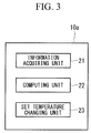
- Fig. 3 is a diagram illustrating a functional block example of the heat source machine controlling apparatus 10a illustrated in Fig. 2 .
- the heat source machine controlling apparatus 10a includes a data acquiring unit 21, a computing unit 22, and a set temperature changing unit 23.
- the data acquiring unit 21 acquires measurement values measured by various sensors, such as the refrigerant condensation pressure Pc, the refrigerant temperature Ts, the cooling water flow rate F2, the cooling water outlet temperature Tcout, the cooling water inlet temperature Tcin, the chilled water flow rate F1, the chilled water outlet temperature Tout, and the chilled water inlet temperature Tin.
- the computing unit 22 calculates a load change rate (an evaluation value on a fluctuation) using the measurement values acquired by the data acquiring unit 21.
- the load change rate is calculated according to, for example, Expression (1) given below.
- Load Change Rate A ⁇ Qe i ⁇ Qe i ⁇ 1 + Qe i ⁇ 1 / Qe i ⁇ 1
- A represents the current load rate, which is a value obtained by dividing the current refrigeration capacity by the rated refrigeration capacity
- Qe(i) represents an average amount of heat exchange of the evaporator 36 in a past predetermined period from the present
- Qe(i-1) represents an average amount of heat exchange of the evaporator 36 in a past predetermined period from the previous sampling cycle.
- the amount of heat exchange Qe of the evaporator 36 is obtained according to Expression (2) given below.
- Qe kW Tin ⁇ Tout ⁇ F 1 ⁇ ⁇ ⁇ c
- Tin represents the chilled water inlet temperature (°C)
- Tout represents the chilled water outlet temperature (°C)
- F1 represents the chilled water flow rate (m 3 /s)
- ⁇ represents the chilled water density (kg/m 3 )
- c represents the specific heat (kJ/kg°C).
- the value can be smoothed using a moving average in this way.
- the past predetermined period can be set as appropriate depending on a design, and is preferably set to, for example, between 100 seconds and 140 seconds. In the present embodiment, the past predetermined period is set to 120 seconds.
- the set temperature changing unit 23 changes a set chilled water outlet temperature by a predetermined amount in the case where the load change rate calculated by the computing unit 22 exceeds a predetermined threshold value.
- the predetermined amount is, for example, a temperature corresponding to approximately 10% of the difference between the chilled water inlet temperature and the set chilled water outlet temperature. For example, in the case where the chilled water inlet temperature is 12°C and where the set chilled water outlet temperature is 7°C, the predetermined amount is 0.5°C.
- the set temperature changing unit 23 decreases the set chilled water outlet temperature by the predetermined amount to increase a heat source machine load. In the case where the load change rate is negative, that is, where the chilled water outlet temperature is on a falling trend, the set temperature changing unit 23 increases the set chilled water outlet temperature by the predetermined amount to decrease the heat source machine load.
- various measurement values such as the refrigerant condensation pressure Pc are collected by the information acquiring unit 21, and the load change rate is computed by the computing unit 22.
- the set temperature changing unit 23 determines whether or not the load change rate computed by the computing unit 22 exceeds the predetermined threshold value. In the case where the load change rate exceeds the threshold value, the set temperature changing unit 23 increases or decreases the set chilled water outlet temperature by the predetermined amount so as to suppress a fluctuation in the chilled water outlet temperature. With such use of the load change rate, a fluctuation in the chilled water outlet temperature can be promptly sensed, and an overshoot can be prevented.
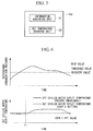
- Figs. 4 are diagrams illustrating effects of the heat source machine 11a and the control method therefor according to the present embodiment.
- the horizontal axis represents the time
- the vertical axis represents the load rate
- the thin solid line represents the load rate corresponding to the set outlet temperature
- the broken line represents the load rate according to a conventional control method
- the thick solid line represents the load rate according to the control method of the present embodiment.
- the horizontal axis represents the time
- the vertical axis represents the chilled water outlet temperature
- the thin solid line represents the set chilled water outlet temperature set by a user, in other words, the initial value (for example, 0°C) of the set chilled water outlet temperature
- the dotted line represents the set chilled water outlet temperature according to the present embodiment
- the thick solid line represents the chilled water outlet temperature according to the present embodiment
- the broken line represents the chilled water outlet temperature according to the conventional control method.
- a change in the load rate is monitored on the basis of the load change rate.
- the set chilled water outlet temperature is changed (see the dotted line at a time t1 in Fig. 4(b) ). If the set chilled water outlet temperature is changed, such control that makes the chilled water outlet temperature coincident with the set chilled water outlet temperature after the change is performed. Consequently, the load rate decreases (see the thick solid line in Fig. 4(a) ), and the chilled water outlet temperature gradually approaches the set chilled water outlet temperature (see the thick solid line in Fig. 4(b) ).
- an overshoot can be suppressed compared with the conventional control method.
- the chilled water outlet temperature is set to around 0°C
- the heat medium may freeze, and chilled water cannot be used as the heat medium.
- the chilled water outlet temperature can be suppressed from becoming 0°C or lower. Consequently, chilled water can be used as the heat medium, and the heat exchange efficiency in the evaporator 36 can be enhanced.
- the set chilled water outlet temperature is changed.
- an amount of change an evaluation value on a fluctuation
- the set chilled water outlet temperature may be changed.
- the amount of fluctuation is calculated using a moving average value as described above, influences of noise can be reduced.
- the change rate may be used instead of the amount of fluctuation. In short, it is sufficient to compute such an evaluation value that reflects a fluctuation in the above-mentioned parameter, and the evaluation function therefor is not particularly limited.
- the load rate fluctuates due to this fluctuation.
- all these parameters influence the load rate. That is, because a fluctuation in these parameters appears as a fluctuation in the load rate, if the load change rate is monitored, conditions of the heat source machine can be efficiently understood.
- the heat source machine according to the present embodiment is different in a function of the heat source machine controlling apparatus.
- points different from the first embodiment are mainly described, and description of points common thereto is omitted.
- Fig. 5 is a functional block diagram of a heat source machine controlling apparatus 10a' according to the present embodiment. As illustrated in Fig. 5 , the heat source machine controlling apparatus 10a' includes the information acquiring unit 21 and a set temperature changing unit 23'.
- the information acquiring unit 21 acquires the refrigerant condensation pressure Pc, the refrigerant temperature Ts, the cooling water flow rate F2, the cooling water outlet temperature Tcout, the cooling water inlet temperature Tcin, the chilled water flow rate F1, the chilled water outlet temperature Tout, the chilled water inlet temperature Tin, and the like.
- the set temperature changing unit 23' determines whether or not the refrigerant condensation pressure Pc of the various measurement values acquired by the information acquiring unit 21 exceeds a predetermined threshold value. In the case where the refrigerant condensation pressure Pc exceeds the predetermined threshold value, the set temperature changing unit 23' increases the set chilled water outlet temperature by a predetermined amount. The amount of this increase may be set as appropriate depending on a design.
- the set chilled water outlet temperature is changed to be higher by the predetermined amount. Because the set chilled water outlet temperature is set to be relatively high, the condensation pressure gradually decreases. Consequently, a forcible stop of the heat source machine can be avoided even under the conditions that the heat source machine load is high and that the outside temperature is high. Moreover, in the case where the refrigerant condensation pressure becomes lower than a predetermined recovery value, the set chilled water outlet temperature may be returned to its initial value.
- the refrigerant condensation temperature may be used instead.
- the set chilled water outlet temperature may be chanted to a value higher by a predetermined amount.
- the present invention is not limited to only the above-mentioned embodiments, and can be variously modified and carried out within the range not departing from the scope of the invention by, for example, partially or entirely combining the above-mentioned embodiments.
Landscapes
- Engineering & Computer Science (AREA)
- Mechanical Engineering (AREA)
- General Engineering & Computer Science (AREA)
- Chemical & Material Sciences (AREA)
- Combustion & Propulsion (AREA)
- Physics & Mathematics (AREA)
- Thermal Sciences (AREA)
- Air Conditioning Control Device (AREA)
Applications Claiming Priority (2)
| Application Number | Priority Date | Filing Date | Title |
|---|---|---|---|
| JP2013235264A JP6324707B2 (ja) | 2013-11-13 | 2013-11-13 | 熱源機及びその制御方法 |
| PCT/JP2014/079324 WO2015072376A1 (fr) | 2013-11-13 | 2014-11-05 | Dispositif source de chaleur et procédé de commande de celui-ci |
Publications (3)
| Publication Number | Publication Date |
|---|---|
| EP3037745A1 true EP3037745A1 (fr) | 2016-06-29 |
| EP3037745A4 EP3037745A4 (fr) | 2017-03-08 |
| EP3037745B1 EP3037745B1 (fr) | 2021-08-11 |
Family
ID=53057312
Family Applications (1)
| Application Number | Title | Priority Date | Filing Date |
|---|---|---|---|
| EP14863022.1A Active EP3037745B1 (fr) | 2013-11-13 | 2014-11-05 | Dispositif source de chaleur et procédé de commande de celui-ci |
Country Status (5)
| Country | Link |
|---|---|
| US (1) | US10174986B2 (fr) |
| EP (1) | EP3037745B1 (fr) |
| JP (1) | JP6324707B2 (fr) |
| CN (1) | CN105593611B (fr) |
| WO (1) | WO2015072376A1 (fr) |
Cited By (2)
| Publication number | Priority date | Publication date | Assignee | Title |
|---|---|---|---|---|
| EP3553403A1 (fr) * | 2018-04-11 | 2019-10-16 | Robert Bosch GmbH | Système cvc et procédé de fonctionnement d'un système cvc |
| EP3534089A4 (fr) * | 2016-10-27 | 2019-11-13 | Chongqing Midea General Refrigeration Equipment Co., Ltd. | Système de climatisation |
Families Citing this family (13)
| Publication number | Priority date | Publication date | Assignee | Title |
|---|---|---|---|---|
| JP6433709B2 (ja) * | 2014-07-30 | 2018-12-05 | 三菱重工サーマルシステムズ株式会社 | ターボ冷凍機及びその制御装置並びにその制御方法 |
| JP6716306B2 (ja) * | 2016-03-23 | 2020-07-01 | 三菱重工サーマルシステムズ株式会社 | 熱源システムの設定温度制御装置、及びそれを備えた熱源システム、並びに熱源システムの設定温度制御方法 |
| JP6890021B2 (ja) * | 2017-02-28 | 2021-06-18 | 三菱重工サーマルシステムズ株式会社 | ターボ冷凍機、及びターボ冷凍機の運転方法 |
| JP6835651B2 (ja) * | 2017-03-31 | 2021-02-24 | 三菱重工サーマルシステムズ株式会社 | 冷凍機制御装置、ターボ冷凍機、冷凍機制御方法およびプログラム |
| JP7017406B2 (ja) * | 2017-12-27 | 2022-02-08 | 三菱重工サーマルシステムズ株式会社 | 制御装置、冷凍機システム、制御方法及びプログラム |
| IT201800001070A1 (it) * | 2018-01-16 | 2019-07-16 | Meno Energia S R L | Metodo e dispositivo per la produzione di acqua refrigerata |
| JP7235460B2 (ja) * | 2018-09-13 | 2023-03-08 | 三菱重工サーマルシステムズ株式会社 | 制御装置、熱源システム、冷却水入口温度下限値の算出方法、制御方法およびプログラム |
| EP4357719A2 (fr) * | 2018-10-05 | 2024-04-24 | S. A. Armstrong Limited | Régulation de débit d'alimentation en avant d'un système de transfert de chaleur |
| EP3978819B1 (fr) * | 2019-06-03 | 2024-01-10 | Daikin Industries, Ltd. | Système de gestion d'appareil |
| CN113028729B (zh) * | 2021-03-30 | 2022-05-10 | 长虹美菱股份有限公司 | 一种冰箱制冷控制方法 |
| CN113418283B (zh) * | 2021-05-14 | 2022-12-13 | 青岛海尔空调电子有限公司 | 用于空调器的控制方法 |
| CN113654134B (zh) * | 2021-07-30 | 2023-05-26 | 青岛海尔空调电子有限公司 | 冷水机组的控制方法 |
| WO2023195125A1 (fr) * | 2022-04-07 | 2023-10-12 | 三菱電機株式会社 | Système à cycle frigorifique |
Family Cites Families (23)
| Publication number | Priority date | Publication date | Assignee | Title |
|---|---|---|---|---|
| JPS63129250A (ja) | 1986-11-18 | 1988-06-01 | 三洋電機株式会社 | 空気調和機の保護装置 |
| JP2810188B2 (ja) * | 1990-02-13 | 1998-10-15 | ヤンマーディーゼル株式会社 | 冷凍機の制御機構 |
| JPH1089783A (ja) * | 1996-09-12 | 1998-04-10 | Sanyo Electric Co Ltd | 冷凍機 |
| US6145751A (en) * | 1999-01-12 | 2000-11-14 | Siemens Building Technologies, Inc. | Method and apparatus for determining a thermal setpoint in a HVAC system |
| US6085532A (en) * | 1999-02-05 | 2000-07-11 | American Standard Inc. | Chiller capacity control with variable chilled water flow compensation |
| JP3236580B2 (ja) | 1999-06-08 | 2001-12-10 | 鹿島建設株式会社 | シールド機、シールド機の掘進方法および斜坑または立坑の構築方法 |
| TW505770B (en) * | 2000-05-02 | 2002-10-11 | Nishiyama Corp | Temperature controller |
| JP2002061925A (ja) * | 2000-08-23 | 2002-02-28 | Daikin Ind Ltd | 空気調和装置 |
| JP3504608B2 (ja) * | 2000-12-06 | 2004-03-08 | イノテック株式会社 | 冷却システム |
| ITGE20020028A1 (it) * | 2002-04-10 | 2003-10-10 | Carpigiani Group Ali Spa | Metodo ed apparato di regolazione della portata di fluido refrigerante in macchine per la produzione di gelato. |
| US6688124B1 (en) * | 2002-11-07 | 2004-02-10 | Carrier Corporation | Electronic expansion valve control for a refrigerant cooled variable frequency drive (VFD) |
| JP2005016872A (ja) | 2003-06-27 | 2005-01-20 | Matsushita Electric Ind Co Ltd | 冷凍冷蔵ユニットおよび冷蔵庫 |
| JP2006153429A (ja) * | 2004-10-25 | 2006-06-15 | Nuflare Technology Inc | 恒温流体供給システム |
| JP4563891B2 (ja) * | 2005-08-11 | 2010-10-13 | 株式会社山武 | 運転台数制御装置および方法 |
| JP4910163B2 (ja) * | 2005-09-30 | 2012-04-04 | Smc株式会社 | 恒温液循環装置及び該装置における温度制御方法 |
| JP4647469B2 (ja) | 2005-11-24 | 2011-03-09 | 新日本空調株式会社 | 空気調和設備の運転方法 |
| JP5091432B2 (ja) * | 2006-06-23 | 2012-12-05 | 日立アプライアンス株式会社 | 熱源装置 |
| US20080006044A1 (en) * | 2006-07-10 | 2008-01-10 | Ziming Tan | Method for controlling temperature |
| JP2012141098A (ja) | 2010-12-28 | 2012-07-26 | Mitsubishi Heavy Ind Ltd | 熱源システムおよびその制御方法 |
| JP5971964B2 (ja) | 2012-02-06 | 2016-08-17 | ジョンソンコントロールズ ヒタチ エア コンディショニング テクノロジー(ホンコン)リミテッド | ターボ冷凍機 |
| JP2013164223A (ja) * | 2012-02-13 | 2013-08-22 | Hitachi Appliances Inc | 熱源システム |
| JP5787792B2 (ja) | 2012-02-29 | 2015-09-30 | 三菱重工業株式会社 | 熱源システムの台数制御装置及びその方法並びに熱源システム |
| WO2013165841A1 (fr) | 2012-04-30 | 2013-11-07 | Johnson Controls Technology Company | Système de commande |
-
2013
- 2013-11-13 JP JP2013235264A patent/JP6324707B2/ja active Active
-
2014
- 2014-11-05 US US15/024,616 patent/US10174986B2/en active Active
- 2014-11-05 CN CN201480053030.7A patent/CN105593611B/zh active Active
- 2014-11-05 EP EP14863022.1A patent/EP3037745B1/fr active Active
- 2014-11-05 WO PCT/JP2014/079324 patent/WO2015072376A1/fr active Application Filing
Cited By (2)
| Publication number | Priority date | Publication date | Assignee | Title |
|---|---|---|---|---|
| EP3534089A4 (fr) * | 2016-10-27 | 2019-11-13 | Chongqing Midea General Refrigeration Equipment Co., Ltd. | Système de climatisation |
| EP3553403A1 (fr) * | 2018-04-11 | 2019-10-16 | Robert Bosch GmbH | Système cvc et procédé de fonctionnement d'un système cvc |
Also Published As
| Publication number | Publication date |
|---|---|
| CN105593611A (zh) | 2016-05-18 |
| CN105593611B (zh) | 2018-05-25 |
| EP3037745B1 (fr) | 2021-08-11 |
| WO2015072376A1 (fr) | 2015-05-21 |
| EP3037745A4 (fr) | 2017-03-08 |
| JP2015094560A (ja) | 2015-05-18 |
| JP6324707B2 (ja) | 2018-05-16 |
| US20160216024A1 (en) | 2016-07-28 |
| US10174986B2 (en) | 2019-01-08 |
Similar Documents
| Publication | Publication Date | Title |
|---|---|---|
| EP3037745A1 (fr) | Dispositif source de chaleur et procédé de commande de celui-ci | |
| EP2821725B1 (fr) | Système de sources de chaleur avec un dispositif de commande de nombre de machines, procédé pour ce système de sources de chaleur | |
| EP2343490B1 (fr) | Pompe à chaleur et procédé pour calculer le débit du milieu de chauffage de la pompe à chaleur | |
| EP2634509B1 (fr) | Appareil de source de chaleur | |
| KR101662468B1 (ko) | 열원시스템 및 냉각수 공급장치의 제어장치 및 제어방법 | |
| EP2330365B1 (fr) | Dispositif d'évaluation de la performance pour dispositif frigorifique centrifuge à vitesse variable | |
| EP2693141B1 (fr) | Estimateur de débit de milieu chaud, source de chaleur et procédé d'estimation du débit de milieu chaud | |
| CN103168204B (zh) | 热媒流量估计装置、热源机以及热媒流量估计方法 | |
| EP2426433A2 (fr) | Dispositif d'évaluation de la performance pour dispositif frigorifique centrifuge | |
| US9341401B2 (en) | Heat source system and control method therefor | |
| JP6855160B2 (ja) | 熱源システムの台数制御装置及びその方法並びに熱源システム | |
| JP5931774B2 (ja) | ターボ冷凍機の最大負荷率算出装置及びその方法並びに熱源システム及びその台数制御方法 | |
| JP6698312B2 (ja) | 制御装置、制御方法、及び熱源システム |
Legal Events
| Date | Code | Title | Description |
|---|---|---|---|
| PUAI | Public reference made under article 153(3) epc to a published international application that has entered the european phase |
Free format text: ORIGINAL CODE: 0009012 |
|
| 17P | Request for examination filed |
Effective date: 20160323 |
|
| AK | Designated contracting states |
Kind code of ref document: A1 Designated state(s): AL AT BE BG CH CY CZ DE DK EE ES FI FR GB GR HR HU IE IS IT LI LT LU LV MC MK MT NL NO PL PT RO RS SE SI SK SM TR |
|
| AX | Request for extension of the european patent |
Extension state: BA ME |
|
| RIC1 | Information provided on ipc code assigned before grant |
Ipc: F24F 11/02 20060101ALI20160928BHEP Ipc: F25B 49/02 20060101ALI20160928BHEP Ipc: F25B 1/053 20060101AFI20160928BHEP |
|
| DAX | Request for extension of the european patent (deleted) | ||
| A4 | Supplementary search report drawn up and despatched |
Effective date: 20170203 |
|
| RIC1 | Information provided on ipc code assigned before grant |
Ipc: F25B 1/053 20060101AFI20170130BHEP Ipc: F25B 49/02 20060101ALI20170130BHEP Ipc: F24F 11/02 20060101ALI20170130BHEP |
|
| RAP1 | Party data changed (applicant data changed or rights of an application transferred) |
Owner name: MITSUBISHI HEAVY INDUSTRIES THERMAL SYSTEMS, LTD. |
|
| STAA | Information on the status of an ep patent application or granted ep patent |
Free format text: STATUS: EXAMINATION IS IN PROGRESS |
|
| 17Q | First examination report despatched |
Effective date: 20200511 |
|
| STAA | Information on the status of an ep patent application or granted ep patent |
Free format text: STATUS: EXAMINATION IS IN PROGRESS |
|
| GRAP | Despatch of communication of intention to grant a patent |
Free format text: ORIGINAL CODE: EPIDOSNIGR1 |
|
| STAA | Information on the status of an ep patent application or granted ep patent |
Free format text: STATUS: GRANT OF PATENT IS INTENDED |
|
| RIC1 | Information provided on ipc code assigned before grant |
Ipc: F25B 1/053 20060101AFI20210224BHEP Ipc: F25B 49/02 20060101ALI20210224BHEP |
|
| INTG | Intention to grant announced |
Effective date: 20210311 |
|
| GRAS | Grant fee paid |
Free format text: ORIGINAL CODE: EPIDOSNIGR3 |
|
| GRAA | (expected) grant |
Free format text: ORIGINAL CODE: 0009210 |
|
| STAA | Information on the status of an ep patent application or granted ep patent |
Free format text: STATUS: THE PATENT HAS BEEN GRANTED |
|
| AK | Designated contracting states |
Kind code of ref document: B1 Designated state(s): AL AT BE BG CH CY CZ DE DK EE ES FI FR GB GR HR HU IE IS IT LI LT LU LV MC MK MT NL NO PL PT RO RS SE SI SK SM TR |
|
| REG | Reference to a national code |
Ref country code: CH Ref legal event code: EP |
|
| REG | Reference to a national code |
Ref country code: DE Ref legal event code: R096 Ref document number: 602014079434 Country of ref document: DE |
|
| REG | Reference to a national code |
Ref country code: IE Ref legal event code: FG4D Ref country code: AT Ref legal event code: REF Ref document number: 1419779 Country of ref document: AT Kind code of ref document: T Effective date: 20210915 |
|
| REG | Reference to a national code |
Ref country code: LT Ref legal event code: MG9D |
|
| REG | Reference to a national code |
Ref country code: NL Ref legal event code: MP Effective date: 20210811 |
|
| REG | Reference to a national code |
Ref country code: AT Ref legal event code: MK05 Ref document number: 1419779 Country of ref document: AT Kind code of ref document: T Effective date: 20210811 |
|
| PG25 | Lapsed in a contracting state [announced via postgrant information from national office to epo] |
Ref country code: FI Free format text: LAPSE BECAUSE OF FAILURE TO SUBMIT A TRANSLATION OF THE DESCRIPTION OR TO PAY THE FEE WITHIN THE PRESCRIBED TIME-LIMIT Effective date: 20210811 Ref country code: ES Free format text: LAPSE BECAUSE OF FAILURE TO SUBMIT A TRANSLATION OF THE DESCRIPTION OR TO PAY THE FEE WITHIN THE PRESCRIBED TIME-LIMIT Effective date: 20210811 Ref country code: NO Free format text: LAPSE BECAUSE OF FAILURE TO SUBMIT A TRANSLATION OF THE DESCRIPTION OR TO PAY THE FEE WITHIN THE PRESCRIBED TIME-LIMIT Effective date: 20211111 Ref country code: PT Free format text: LAPSE BECAUSE OF FAILURE TO SUBMIT A TRANSLATION OF THE DESCRIPTION OR TO PAY THE FEE WITHIN THE PRESCRIBED TIME-LIMIT Effective date: 20211213 Ref country code: LT Free format text: LAPSE BECAUSE OF FAILURE TO SUBMIT A TRANSLATION OF THE DESCRIPTION OR TO PAY THE FEE WITHIN THE PRESCRIBED TIME-LIMIT Effective date: 20210811 Ref country code: AT Free format text: LAPSE BECAUSE OF FAILURE TO SUBMIT A TRANSLATION OF THE DESCRIPTION OR TO PAY THE FEE WITHIN THE PRESCRIBED TIME-LIMIT Effective date: 20210811 Ref country code: BG Free format text: LAPSE BECAUSE OF FAILURE TO SUBMIT A TRANSLATION OF THE DESCRIPTION OR TO PAY THE FEE WITHIN THE PRESCRIBED TIME-LIMIT Effective date: 20211111 Ref country code: HR Free format text: LAPSE BECAUSE OF FAILURE TO SUBMIT A TRANSLATION OF THE DESCRIPTION OR TO PAY THE FEE WITHIN THE PRESCRIBED TIME-LIMIT Effective date: 20210811 Ref country code: SE Free format text: LAPSE BECAUSE OF FAILURE TO SUBMIT A TRANSLATION OF THE DESCRIPTION OR TO PAY THE FEE WITHIN THE PRESCRIBED TIME-LIMIT Effective date: 20210811 Ref country code: RS Free format text: LAPSE BECAUSE OF FAILURE TO SUBMIT A TRANSLATION OF THE DESCRIPTION OR TO PAY THE FEE WITHIN THE PRESCRIBED TIME-LIMIT Effective date: 20210811 |
|
| PG25 | Lapsed in a contracting state [announced via postgrant information from national office to epo] |
Ref country code: PL Free format text: LAPSE BECAUSE OF FAILURE TO SUBMIT A TRANSLATION OF THE DESCRIPTION OR TO PAY THE FEE WITHIN THE PRESCRIBED TIME-LIMIT Effective date: 20210811 Ref country code: LV Free format text: LAPSE BECAUSE OF FAILURE TO SUBMIT A TRANSLATION OF THE DESCRIPTION OR TO PAY THE FEE WITHIN THE PRESCRIBED TIME-LIMIT Effective date: 20210811 Ref country code: GR Free format text: LAPSE BECAUSE OF FAILURE TO SUBMIT A TRANSLATION OF THE DESCRIPTION OR TO PAY THE FEE WITHIN THE PRESCRIBED TIME-LIMIT Effective date: 20211112 |
|
| PG25 | Lapsed in a contracting state [announced via postgrant information from national office to epo] |
Ref country code: NL Free format text: LAPSE BECAUSE OF FAILURE TO SUBMIT A TRANSLATION OF THE DESCRIPTION OR TO PAY THE FEE WITHIN THE PRESCRIBED TIME-LIMIT Effective date: 20210811 |
|
| PG25 | Lapsed in a contracting state [announced via postgrant information from national office to epo] |
Ref country code: DK Free format text: LAPSE BECAUSE OF FAILURE TO SUBMIT A TRANSLATION OF THE DESCRIPTION OR TO PAY THE FEE WITHIN THE PRESCRIBED TIME-LIMIT Effective date: 20210811 |
|
| REG | Reference to a national code |
Ref country code: DE Ref legal event code: R097 Ref document number: 602014079434 Country of ref document: DE |
|
| PG25 | Lapsed in a contracting state [announced via postgrant information from national office to epo] |
Ref country code: SM Free format text: LAPSE BECAUSE OF FAILURE TO SUBMIT A TRANSLATION OF THE DESCRIPTION OR TO PAY THE FEE WITHIN THE PRESCRIBED TIME-LIMIT Effective date: 20210811 Ref country code: SK Free format text: LAPSE BECAUSE OF FAILURE TO SUBMIT A TRANSLATION OF THE DESCRIPTION OR TO PAY THE FEE WITHIN THE PRESCRIBED TIME-LIMIT Effective date: 20210811 Ref country code: RO Free format text: LAPSE BECAUSE OF FAILURE TO SUBMIT A TRANSLATION OF THE DESCRIPTION OR TO PAY THE FEE WITHIN THE PRESCRIBED TIME-LIMIT Effective date: 20210811 Ref country code: EE Free format text: LAPSE BECAUSE OF FAILURE TO SUBMIT A TRANSLATION OF THE DESCRIPTION OR TO PAY THE FEE WITHIN THE PRESCRIBED TIME-LIMIT Effective date: 20210811 Ref country code: CZ Free format text: LAPSE BECAUSE OF FAILURE TO SUBMIT A TRANSLATION OF THE DESCRIPTION OR TO PAY THE FEE WITHIN THE PRESCRIBED TIME-LIMIT Effective date: 20210811 Ref country code: AL Free format text: LAPSE BECAUSE OF FAILURE TO SUBMIT A TRANSLATION OF THE DESCRIPTION OR TO PAY THE FEE WITHIN THE PRESCRIBED TIME-LIMIT Effective date: 20210811 |
|
| REG | Reference to a national code |
Ref country code: DE Ref legal event code: R119 Ref document number: 602014079434 Country of ref document: DE |
|
| PLBE | No opposition filed within time limit |
Free format text: ORIGINAL CODE: 0009261 |
|
| STAA | Information on the status of an ep patent application or granted ep patent |
Free format text: STATUS: NO OPPOSITION FILED WITHIN TIME LIMIT |
|
| PG25 | Lapsed in a contracting state [announced via postgrant information from national office to epo] |
Ref country code: MC Free format text: LAPSE BECAUSE OF FAILURE TO SUBMIT A TRANSLATION OF THE DESCRIPTION OR TO PAY THE FEE WITHIN THE PRESCRIBED TIME-LIMIT Effective date: 20210811 |
|
| REG | Reference to a national code |
Ref country code: CH Ref legal event code: PL |
|
| 26N | No opposition filed |
Effective date: 20220512 |
|
| GBPC | Gb: european patent ceased through non-payment of renewal fee |
Effective date: 20211111 |
|
| PG25 | Lapsed in a contracting state [announced via postgrant information from national office to epo] |
Ref country code: LU Free format text: LAPSE BECAUSE OF NON-PAYMENT OF DUE FEES Effective date: 20211105 Ref country code: IT Free format text: LAPSE BECAUSE OF FAILURE TO SUBMIT A TRANSLATION OF THE DESCRIPTION OR TO PAY THE FEE WITHIN THE PRESCRIBED TIME-LIMIT Effective date: 20210811 Ref country code: BE Free format text: LAPSE BECAUSE OF NON-PAYMENT OF DUE FEES Effective date: 20211130 |
|
| REG | Reference to a national code |
Ref country code: BE Ref legal event code: MM Effective date: 20211130 |
|
| PG25 | Lapsed in a contracting state [announced via postgrant information from national office to epo] |
Ref country code: SI Free format text: LAPSE BECAUSE OF FAILURE TO SUBMIT A TRANSLATION OF THE DESCRIPTION OR TO PAY THE FEE WITHIN THE PRESCRIBED TIME-LIMIT Effective date: 20210811 Ref country code: LI Free format text: LAPSE BECAUSE OF NON-PAYMENT OF DUE FEES Effective date: 20211130 Ref country code: CH Free format text: LAPSE BECAUSE OF NON-PAYMENT OF DUE FEES Effective date: 20211130 |
|
| PG25 | Lapsed in a contracting state [announced via postgrant information from national office to epo] |
Ref country code: IE Free format text: LAPSE BECAUSE OF NON-PAYMENT OF DUE FEES Effective date: 20211105 Ref country code: GB Free format text: LAPSE BECAUSE OF NON-PAYMENT OF DUE FEES Effective date: 20211111 Ref country code: DE Free format text: LAPSE BECAUSE OF NON-PAYMENT OF DUE FEES Effective date: 20220601 |
|
| PG25 | Lapsed in a contracting state [announced via postgrant information from national office to epo] |
Ref country code: FR Free format text: LAPSE BECAUSE OF NON-PAYMENT OF DUE FEES Effective date: 20211130 |
|
| PG25 | Lapsed in a contracting state [announced via postgrant information from national office to epo] |
Ref country code: HU Free format text: LAPSE BECAUSE OF FAILURE TO SUBMIT A TRANSLATION OF THE DESCRIPTION OR TO PAY THE FEE WITHIN THE PRESCRIBED TIME-LIMIT; INVALID AB INITIO Effective date: 20141105 |
|
| PG25 | Lapsed in a contracting state [announced via postgrant information from national office to epo] |
Ref country code: CY Free format text: LAPSE BECAUSE OF FAILURE TO SUBMIT A TRANSLATION OF THE DESCRIPTION OR TO PAY THE FEE WITHIN THE PRESCRIBED TIME-LIMIT Effective date: 20210811 |
|
| PGFP | Annual fee paid to national office [announced via postgrant information from national office to epo] |
Ref country code: TR Payment date: 20231103 Year of fee payment: 10 |
|
| PG25 | Lapsed in a contracting state [announced via postgrant information from national office to epo] |
Ref country code: MK Free format text: LAPSE BECAUSE OF FAILURE TO SUBMIT A TRANSLATION OF THE DESCRIPTION OR TO PAY THE FEE WITHIN THE PRESCRIBED TIME-LIMIT Effective date: 20210811 |