EP3037324A1 - Elektrische servolenkvorrichtung - Google Patents
Elektrische servolenkvorrichtung Download PDFInfo
- Publication number
- EP3037324A1 EP3037324A1 EP15201277.9A EP15201277A EP3037324A1 EP 3037324 A1 EP3037324 A1 EP 3037324A1 EP 15201277 A EP15201277 A EP 15201277A EP 3037324 A1 EP3037324 A1 EP 3037324A1
- Authority
- EP
- European Patent Office
- Prior art keywords
- worm wheel
- worm
- output shaft
- electric power
- steering device
- Prior art date
- Legal status (The legal status is an assumption and is not a legal conclusion. Google has not performed a legal analysis and makes no representation as to the accuracy of the status listed.)
- Granted
Links
- 230000005540 biological transmission Effects 0.000 claims abstract description 11
- 239000003638 chemical reducing agent Substances 0.000 claims description 12
- 230000002093 peripheral effect Effects 0.000 description 6
- 239000011295 pitch Substances 0.000 description 4
- 230000000694 effects Effects 0.000 description 2
- 230000004907 flux Effects 0.000 description 2
- 230000001788 irregular Effects 0.000 description 2
- 230000009977 dual effect Effects 0.000 description 1
Images


Classifications
-
- B—PERFORMING OPERATIONS; TRANSPORTING
- B62—LAND VEHICLES FOR TRAVELLING OTHERWISE THAN ON RAILS
- B62D—MOTOR VEHICLES; TRAILERS
- B62D5/00—Power-assisted or power-driven steering
- B62D5/04—Power-assisted or power-driven steering electrical, e.g. using an electric servo-motor connected to, or forming part of, the steering gear
- B62D5/0403—Power-assisted or power-driven steering electrical, e.g. using an electric servo-motor connected to, or forming part of, the steering gear characterised by constructional features, e.g. common housing for motor and gear box
-
- B—PERFORMING OPERATIONS; TRANSPORTING
- B62—LAND VEHICLES FOR TRAVELLING OTHERWISE THAN ON RAILS
- B62D—MOTOR VEHICLES; TRAILERS
- B62D5/00—Power-assisted or power-driven steering
- B62D5/04—Power-assisted or power-driven steering electrical, e.g. using an electric servo-motor connected to, or forming part of, the steering gear
- B62D5/0409—Electric motor acting on the steering column
-
- B—PERFORMING OPERATIONS; TRANSPORTING
- B62—LAND VEHICLES FOR TRAVELLING OTHERWISE THAN ON RAILS
- B62D—MOTOR VEHICLES; TRAILERS
- B62D5/00—Power-assisted or power-driven steering
- B62D5/04—Power-assisted or power-driven steering electrical, e.g. using an electric servo-motor connected to, or forming part of, the steering gear
- B62D5/0442—Conversion of rotational into longitudinal movement
- B62D5/0454—Worm gears
-
- B—PERFORMING OPERATIONS; TRANSPORTING
- B62—LAND VEHICLES FOR TRAVELLING OTHERWISE THAN ON RAILS
- B62D—MOTOR VEHICLES; TRAILERS
- B62D5/00—Power-assisted or power-driven steering
- B62D5/04—Power-assisted or power-driven steering electrical, e.g. using an electric servo-motor connected to, or forming part of, the steering gear
- B62D5/043—Power-assisted or power-driven steering electrical, e.g. using an electric servo-motor connected to, or forming part of, the steering gear characterised by clutch means between driving element, e.g. motor, and driven element, e.g. steering column or steering gear
Definitions
- the invention relates to an electric power steering device.
- the EPS includes a steering column 100 and a steering shaft 102 that is rotatably inserted in the steering column 100, and a housing 104 is integrally connected to a front part of the steering column 100.
- the housing 104 has an axial hole 106 in which an output shaft 108, which constitutes a part of the steering shaft 102, is rotatably supported via bearings 110, 112 and 114.
- a worm wheel 116 is attached to and press-fitted to the output shaft 108 such that the worm wheel 116 is unable to rotate relative to the output shaft 108, for example, through a key connection, and the worm wheel 116 meshes with a worm 118 that is connected to an output shaft of a motor (not shown).
- the bearings 110, 112 and 114 are attached to the axial hole 106 by press-fitting.
- the steering force that is generated when a driver operates a steering wheel (not shown) that is connected to the steering shaft 102 is transmitted via the steering shaft 102 to the output shaft 108 and then to steered wheels (not shown) via, for example, a rack-and-pinion steering device.
- the rotary force of the motor is transmitted via the worm 118 and the worm wheel 116 to the output shaft 108.
- JP 2014-156177 A An electric power steering device that has the above-described structure, which is described in, for example, Japanese Patent Application Publication No. 2014-156177 ( JP 2014-156177 A ), is known.
- the motor and the steering wheel receive an excessive reverse input from the steered wheel and are rotated at a high speed.
- the worm wheel which is connected to the output shaft by press-fitting, may be released from the output shaft and moved in an axial direction of the output shaft.
- the electric power steering device becomes unable to provide power assistance.
- the invention provides an electric power steering device that does not become unable to provide power assistance even when fixing of a worm wheel to an output shaft is released.
- An electric power steering device includes a power assist actuator that includes a motor and a worm reducer; and a restricting portion.
- the worm reducer includes a worm that is connected to a drive shaft of the motor, a worm wheel that meshes with the worm and is attached to an output shaft of the power assist actuator such that the worm wheel is unable to rotate relative to the output shaft, and a housing that accommodates the worm wheel.
- the electric power steering device is configured to provide power assistance via the output shaft.
- the restricting portion is provided on at least one of surfaces of the housing and the worm wheel, the surfaces facing each other.
- the restricting portion is configured to restrict movement of the worm wheel to maintain a meshing relationship between the worm and the worm wheel that allows torque transmission between the worm and the worm wheel, when fixing of the worm wheel to the output shaft in an axial direction of the output shaft is released and the worm wheel is moved in the axial direction.
- An aspect of the invention relates to an electric power steering device including a power assist actuator that includes a motor and a worm reducer.
- the worm reducer includes a worm that is connected to a drive shaft of the motor, a worm wheel that meshes with the worm and is attached to an output shaft of the power assist actuator such that the worm wheel is unable to rotate relative to the output shaft, and a housing that accommodates the worm wheel.
- the electric power steering device is configured to provide power assistance via the output shaft.
- the electric power steering device includes a restricting portion that is provided on at least one of surfaces of the housing and the worm wheel, the surfaces facing each other.
- the restricting portion is configured to restrict movement of the worm wheel to maintain a meshing relationship between the worm and the worm wheel that allows torque transmission between the worm and the worm wheel, when fixing of the worm wheel to the output shaft in an axial direction of the output shaft is released and the worm wheel is moved in the axial direction.
- a bearing may be provided in the housing, and the bearing may support the output shaft such that the output shaft is rotatable; and the restricting portion may be provided at least on an inner surface of the housing that faces one axial side surface of the worm wheel, and the restriction portion may be located closer to the one axial side surface than the bearing is.
- the restricting portion may be a projecting portion that projects from at least one axial side surface of the worm wheel toward an inner surface of the housing.
- the restricting portion restricts movement of the worm wheel in the axial direction of the output shaft to maintain the meshing relationship between the worm and the worm wheel that allows torque transmission therebetween.
- the EPS 1 includes a steering shaft 2 that has a column shaft 3, as its input side end portion, which is rotatably accommodated in a steering column 6 via a bearing 4.
- a steering wheel (not shown) is fixed to one end (a right end portion in FIG. 1 ) of the steering shaft 2. The other end (a left end portion in FIG.
- a steering shaft 2 is connected to an intermediate shaft (not shown) via a universal joint, and rotation and steering torque that result from a steering operation thereof are transmitted to a steering mechanism (not shown), such as a steering gear (rack-and-pinion mechanism), which changes the steering angle of steered wheels.
- a steering mechanism such as a steering gear (rack-and-pinion mechanism), which changes the steering angle of steered wheels.
- the column shaft 3 includes a hollow upper shaft 8 to which the steering wheel is fixed to constitute a steering side end portion of the column shaft 3, and a lower shaft 9 that is spline-fitted to the upper shaft 8 to allow sliding movement of the upper shaft 8 in an axial direction.
- the steering column 6 includes an outer tube 11 that accommodates and supports the upper shaft 8 via the bearing 4, and an inner tube 12 that accommodates the lower shaft 9.
- the inner tube 12 is inserted in the outer tube 11, and the outer tube 11 is provided so as to be slidable in the axial direction relative to the inner tube 12.
- the EPS 1 is constituted as a column-type EPS.
- the column shaft 3 of this embodiment is formed by connecting an output shaft 16 of a power assist actuator 15 to the other end of the lower shaft 9 that is connected to the upper shaft 8 as described above.
- a housing 21 is attached and fixed to a front end portion of the outer tube 11.
- the housing 21 includes a sensor accommodating housing portion 22 that is attached to the inner tube 12, and a mechanism accommodating housing portion 24 that is attached and fixed to the sensor accommodating housing portion 22.
- the sensor accommodating housing portion 22 has a cylindrical tube portion 26 that has one end that is fixedly fitted in an end portion of the inner tube 12, and an enlarged-diameter portion 28 that is formed to have an enlarged diameter at the other end of the tube portion 26.
- the mechanism accommodating housing portion 24 is a housing that accommodates the power assist actuator 15, which provides steering assist force to the steering shaft 2. As shown in FIG. 2 , the mechanism accommodating housing portion 24 includes a bottomed cylindrical worm wheel accommodating portion 25 that includes a bottom wall 25a and a peripheral wall 25b that extends from a circumferential portion of the bottom wall 25a.
- the mechanism accommodating housing portion 24 supports a motor (not shown) as a driving source for the power assist actuator 15 and a controller (not shown) that controls the motor.
- the enlarged-diameter portion 28 is formed to have a cylindrical shape including a bottom wall 28a and a peripheral wall 28b that extends from the bottom wall 28a.
- the peripheral wall 28b is formed to have a height which is smaller than that of the peripheral wall 25b of the worm wheel accommodating portion 25, and a distal end portion of the peripheral wall 25b is fitted to an outer periphery of the peripheral wall 28b.
- the lower shaft 9 includes a hollow spline fitting portion 9a at an end portion on the housing 21-side.
- a connecting member 30 is inserted in and connected to the spline fitting portion 9a such that the connecting member 30 is unable to rotate relative to the spline fitting portion 9a, and one end of a torsion bar 32 that is inserted through the connecting member 30 is fixed to the spline fitting portion 9a.
- the other end portion of the torsion bar 32 is connected to the output shaft 16 such that the other end portion of the torsion bar 32 is unable to rotate relative to the output shaft 16.
- the connecting member 30 is supported by the sensor accommodating housing portion 22 via a bearing 34 that is disposed on an inner periphery of the tube portion 26.
- the torsion bar 32 is twisted in accordance with steering torque from the steering wheel (not shown), which is given by the driver, and the amount of twist of the torsion bar 32 is detected by a torque sensor 36 that is disposed around the connecting member 30 as shown in FIG. 2 .
- the torque sensor 36 is constituted by a magnet 38 that is fixed to an outer periphery of the connecting member 30, and a magnetic sensor (Hall IC) 40 that is located at a position facing the magnet 38 on an inner periphery of the tube portion 26 to detect a change in magnetic flux of the magnet 38.
- the torque sensor 36 detects the steering torque that is transmitted via the steering shaft 2 (column shaft 3) by detecting an angle of twist between the connecting member 30 and the output shaft 16, in other words, twist of the torsion bar 32, as a change in magnetic flux with the use of the magnetic sensor 40.
- An output signal from the torque sensor 36 is output to the controller (not shown), and the controller supplies a motor current in accordance with the steering torque to the motor (not shown).
- the output shaft 16 is rotatably supported by the housing 21 via a bearing 44 that is provided on the bottom wall 25a of the worm wheel accommodating portion 25 and a bearing 46 that is provided on the bottom wall 28a of the enlarged-diameter portion 28.
- the bearing 44 is press-fitted from inside into a mounting hole 25c with a step portion 25d that is provided in a boss 25f that bulges inward in the bottom wall 25a until the bearing 44 engages with the step portion 25d, and a C-shaped snap ring 25e is fitted in a circumferential groove in an inner surface of the mounting hole 25c.
- the bearing 44 is prevented from falling off in the axial direction of the output shaft 16.
- the bottom wall 28a of the enlarged-diameter portion 28 has a boss 28d, and the bearing 46 is press-fitted from inside into a mounting hole 28c that is provided in the boss 28d.
- a hole of the mounting hole 28c, which communicates with the torque sensor 36-side, has a diameter that is smaller than the outside diameter of an outer ring of the bearing 46.
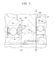
- a bulged portion 16a that has a diameter that is larger than the inside diameters of inner rings of the bearings 44 and 46 is formed at a portion of the output shaft 16 corresponding to the worm wheel accommodating portion 25. As shown in FIG. 3 , an end portion of the bulged portion 16a that faces the bearing 44 contacts the inner ring of the bearing 44, and an end portion of the bulged portion 16a that faces the bearing 46 contacts the inner ring of the bearing 46.
- a worm wheel 42 is attached to the bulged portion 16a of the output shaft 16 such that the worm wheel 42 is unable to rotate relative to the bulged portion 16a, by a fixing portion such as a key connection.
- the fixing portion is a concept that includes press-fitting.
- the worm wheel 42 is fixed to the bulged portion 16a by the fixing portion, such as a key connection, unless an excessive external force is input.
- the motor includes a drive shaft to which a worm (not shown) is attached, and the worm meshes with the worm wheel 42.
- the worm and the worm wheel 42 constitute a worm reducer.
- the power assist actuator 15 is constituted by the motor and the worm reducer.
- a gap G2 between the boss 28d of the enlarged-diameter portion 28 and the worm wheel 42 is set to be shorter than a gap G1 between the worm wheel 42 and the bearing 46.
- a thick portion 42a that has a larger axial thickness is formed at a portion of the worm wheel 42 through which the output shaft 16 extends.
- a distal end of the thick portion 42a and the snap ring 25e on the bearing 44-side are set and disposed to have a gap G3 therebetween.
- the gaps G2 and G3 provide spaces in which the worm wheel 42 is allowed to move in the axial direction on the bulged portion 16a if the worm wheel 42 and the output shaft 16, which have been fixed to each other in the axial direction by a fixing portion such as a key connection, are released from each other (i.e., if the fixing of the worm wheel 42 to the output shaft 16 in the axial direction by a fixing portion such as a key connection is released).
- the gap G3 provides a space in which the thick portion 42a can be moved until the thick portion 42a contacts the snap ring 25e.
- the gap G2 provides a space in which the worm wheel 42 can be moved until a side surface of the worm wheel 42 that faces the bearing 46 contacts the boss 28d when the worm wheel 42 is moved toward the bearing 46.
- the lengths of the gaps G2 and G3 in the axial direction are set such that the worm and the worm wheel 42 maintain a meshing relationship that allows torque transmission therebetween even when the worm wheel 42 is moved by the length of the gap G2 or the gap G3.
- the boss 28d and the snap ring 25e correspond to restricting portions.
- the lengths of the gaps G2 and G3 in the axial direction depend on the sizes and shapes of the worm and worm wheel, each of the lengths of the gaps G2 and G3 in the axial direction is around 1 mm in this embodiment. This value is an example and each of the lengths is not limited to the value.
- the speed of rotation of the motor (not shown) is reduced with the use of the reducer that is constituted by the worm wheel 42 and the worm (not shown), and the rotation is transmitted to the output shaft 16 of the power assist actuator 15.
- the power assist actuator 15 is able to provide power assistance to the steering system.
- the vehicle can be steered even if the worm wheel 42 is moved in the axial direction relative to the output shaft 16 and thus the worm wheel 42 is not fixed to the output shaft 16 in the axial direction. Accordingly, the vehicle can be steered in an emergency.
- the EPS 1 of this embodiment includes the boss 28d and the snap ring 25e (restricting portions), which restrict movement of the worm wheel 42 to maintain the meshing relationship between the worm and the worm wheel 42 that allows torque transmission therebetween when the worm wheel 42 is moved in the axial direction of the output shaft 16.
- the bearing 46 is provided in the housing 21, the bearing 46 supporting the output shaft 16 such that the output shaft 16 is rotatable.
- the boss 28d (restricting portion) of the bottom wall 28a is provided in an inner surface of the housing 21 that faces one axial side surface of the worm wheel 42 (i.e., one side surface in the axial direction), and the boss 28d is located closer to the one axial side surface of the worm wheel 42 than the bearing 46 is. In other words, the boss 28d protrudes toward the one axial side surface of the worm wheel 42.
- the invention is not limited to the embodiment and may be modified as follows.
- the boss 28d is the restricting portion in the embodiment, the restricting portion is not limited to the boss 28d.
- a projecting portion having a height from the bottom wall 28a that is greater than that of the boss 28d may be formed as a restricting portion.
- the projecting portion and the worm wheel 42 are formed to have a gap G2 therebetween.
- the shape of the projecting portion and the number of the projecting portions are not limited.
- the projecting portion may be formed in a cylindrical shape that surrounds the boss 28d or a plurality of projecting portions may be arranged around the boss 28d at predetermined regular pitches or irregular pitches.
- a projecting portion 42b as a restricting portion may be provided on the worm wheel 42 with a gap G2 between the projecting portion 42b and the bottom wall 28a as shown in FIG. 4 .
- projecting portions that can contact each other may be respectively provided as restricting portions on the worm wheel 42 and the bottom wall 28a.
- the shape of the projecting portion 42b and the number of the projecting portions 42b are not limited.
- the projecting portion 42b may be formed in a cylindrical shape that surrounds the boss 28d (refer to FIG. 4 ), or a plurality of projecting portions 42b may be arranged around the boss 28d at predetermined regular pitches or irregular pitches.
- the projecting portion that is provided on the worm wheel 42 may be provided on a side surface that faces the bottom wall 25a instead of being provided to face the bottom wall 28a.
- the projecting portion 42b may be provided on the side surface that faces the bottom wall 28a with another projecting portion provided on the side surface of the worm wheel 42 that faces the bottom wall 25a.
- a gap G3 is provided between the bottom wall 25a and the projecting portion that is provided on the side surface of the worm wheel 42 that faces the bottom wall 25a. Also, in this case, a gap that is greater than the gap G3 is provided between the thick portion 42a and the snap ring 25e.
- the boss 28d of the bottom wall 28a is provided on the inner surface of the sensor accommodating housing portion 22 (the housing 21) that faces one axial side surface of the worm wheel 42, and the boss 28d is located closer to the one axial side surface of the worm wheel 42 than the bearing 46 is.
- the boss 25f of the bottom wall 25a may be located closer to the other axial side surface of the worm wheel 42 than the bearing 44 is, and a gap G3 may be provided between the boss 25f and the other axial side surface of the worm wheel 42. In this case, a gap that is greater than the gap G3 is provided between the thick portion 42a and the snap ring 25e.
- a snap ring may be used to prevent the bearing 46 from coming out of the mounting hole 28c as in the case of the bearing 44.
- EPS column type electric power steering device
- this invention may be implemented as a pinion assist type or dual pinion assist type EPS, for example.
Landscapes
- Engineering & Computer Science (AREA)
- Chemical & Material Sciences (AREA)
- Combustion & Propulsion (AREA)
- Transportation (AREA)
- Mechanical Engineering (AREA)
- Power Steering Mechanism (AREA)
Applications Claiming Priority (1)
| Application Number | Priority Date | Filing Date | Title |
|---|---|---|---|
| JP2014259010A JP6396201B2 (ja) | 2014-12-22 | 2014-12-22 | 電動パワーステアリング装置 |
Publications (2)
| Publication Number | Publication Date |
|---|---|
| EP3037324A1 true EP3037324A1 (de) | 2016-06-29 |
| EP3037324B1 EP3037324B1 (de) | 2018-02-14 |
Family
ID=54850436
Family Applications (1)
| Application Number | Title | Priority Date | Filing Date |
|---|---|---|---|
| EP15201277.9A Active EP3037324B1 (de) | 2014-12-22 | 2015-12-18 | Elektrische servolenkvorrichtung |
Country Status (4)
| Country | Link |
|---|---|
| US (1) | US9783225B2 (de) |
| EP (1) | EP3037324B1 (de) |
| JP (1) | JP6396201B2 (de) |
| CN (1) | CN105711639B (de) |
Families Citing this family (5)
| Publication number | Priority date | Publication date | Assignee | Title |
|---|---|---|---|---|
| JP2016211615A (ja) * | 2015-04-30 | 2016-12-15 | 株式会社ジェイテクト | ウォーム減速機およびステアリング装置 |
| KR20170027170A (ko) * | 2015-09-01 | 2017-03-09 | 주식회사 만도 | 자동차의 조향컬럼 |
| US20180118259A1 (en) * | 2016-10-31 | 2018-05-03 | Steering Solutions Ip Holding Corporation | Torsion bar for a steering system assembly |
| DE102017221153A1 (de) * | 2017-11-27 | 2019-05-29 | Ford Global Technologies, Llc | Lageranordnung und Lenkgetriebe |
| JP7018045B2 (ja) * | 2019-09-06 | 2022-02-09 | ジェコー株式会社 | アクチュエータ及び排気バルブ駆動装置 |
Citations (7)
| Publication number | Priority date | Publication date | Assignee | Title |
|---|---|---|---|---|
| US1843875A (en) * | 1928-12-03 | 1932-02-02 | Alliance Machine Co | Worm drive |
| GB762032A (en) * | 1954-06-14 | 1956-11-21 | Donald Mayer King | Improvements in or relating to gearing |
| DE19811784A1 (de) * | 1998-03-18 | 1999-09-23 | Mannesmann Vdo Ag | Elektrische Lenkhilfe |
| DE10192745B4 (de) * | 2000-06-19 | 2007-03-29 | Nsk Ltd. | Elektrische Hilfskraftvorrichtung |
| EP1887254A2 (de) * | 2006-08-11 | 2008-02-13 | JTEKT Corporation | Elektrische Servolenkung |
| US20120241246A1 (en) * | 2009-12-28 | 2012-09-27 | Jtekt Corporation | Electric power steering device |
| JP2014156177A (ja) | 2013-02-15 | 2014-08-28 | Jtekt Corp | ステアリングコラム装置 |
Family Cites Families (13)
| Publication number | Priority date | Publication date | Assignee | Title |
|---|---|---|---|---|
| DE1966911A1 (de) * | 1969-08-08 | 1975-04-24 | Daimler Benz Ag | Servolenkung fuer fahrzeuge |
| JP3532122B2 (ja) * | 1999-06-29 | 2004-05-31 | 富士機工株式会社 | 電動転舵ステアリングコラム |
| JP3661086B2 (ja) * | 2000-05-25 | 2005-06-15 | 光洋精工株式会社 | 電動式舵取装置 |
| JP2003095119A (ja) * | 2001-09-25 | 2003-04-03 | Koyo Seiko Co Ltd | 電動式パワーステアリング装置 |
| JP3967191B2 (ja) * | 2002-05-10 | 2007-08-29 | 株式会社ショーワ | 電動モータ装置 |
| DE60321014D1 (de) * | 2002-07-03 | 2008-06-26 | Nsk Ltd | Motorservolenksystem |
| CN100577490C (zh) * | 2004-04-06 | 2010-01-06 | 日本精工株式会社 | 电动转向装置 |
| KR20070057250A (ko) * | 2004-10-22 | 2007-06-04 | 닛본 세이고 가부시끼가이샤 | 전동 파워 스티어링 장치 |
| JP2006206005A (ja) * | 2005-01-31 | 2006-08-10 | Nsk Ltd | 電動パワーステアリング装置 |
| JP2006232243A (ja) * | 2005-02-28 | 2006-09-07 | Showa Corp | 電動舵取補助装置 |
| JP2012040980A (ja) * | 2010-08-20 | 2012-03-01 | Showa Corp | 電動パワーステアリング装置 |
| JP5403064B2 (ja) * | 2010-10-06 | 2014-01-29 | 日本精工株式会社 | 電動パワーステアリング装置 |
| JP6031960B2 (ja) | 2012-11-20 | 2016-11-24 | 株式会社ジェイテクト | ステアリング装置 |
-
2014
- 2014-12-22 JP JP2014259010A patent/JP6396201B2/ja active Active
-
2015
- 2015-12-14 US US14/967,900 patent/US9783225B2/en active Active
- 2015-12-14 CN CN201510924551.1A patent/CN105711639B/zh active Active
- 2015-12-18 EP EP15201277.9A patent/EP3037324B1/de active Active
Patent Citations (7)
| Publication number | Priority date | Publication date | Assignee | Title |
|---|---|---|---|---|
| US1843875A (en) * | 1928-12-03 | 1932-02-02 | Alliance Machine Co | Worm drive |
| GB762032A (en) * | 1954-06-14 | 1956-11-21 | Donald Mayer King | Improvements in or relating to gearing |
| DE19811784A1 (de) * | 1998-03-18 | 1999-09-23 | Mannesmann Vdo Ag | Elektrische Lenkhilfe |
| DE10192745B4 (de) * | 2000-06-19 | 2007-03-29 | Nsk Ltd. | Elektrische Hilfskraftvorrichtung |
| EP1887254A2 (de) * | 2006-08-11 | 2008-02-13 | JTEKT Corporation | Elektrische Servolenkung |
| US20120241246A1 (en) * | 2009-12-28 | 2012-09-27 | Jtekt Corporation | Electric power steering device |
| JP2014156177A (ja) | 2013-02-15 | 2014-08-28 | Jtekt Corp | ステアリングコラム装置 |
Also Published As
| Publication number | Publication date |
|---|---|
| JP2016117426A (ja) | 2016-06-30 |
| EP3037324B1 (de) | 2018-02-14 |
| JP6396201B2 (ja) | 2018-09-26 |
| CN105711639B (zh) | 2019-05-17 |
| US20160176438A1 (en) | 2016-06-23 |
| CN105711639A (zh) | 2016-06-29 |
| US9783225B2 (en) | 2017-10-10 |
Similar Documents
| Publication | Publication Date | Title |
|---|---|---|
| EP3037324B1 (de) | Elektrische servolenkvorrichtung | |
| JP6020893B2 (ja) | 電動パワーステアリング装置 | |
| EP2597014B1 (de) | Elektrisches Servolenksystem | |
| JP2011020489A (ja) | 操舵制御装置 | |
| JP2008044426A (ja) | 電動パワーステアリング装置 | |
| US10323994B2 (en) | Torque Sensors | |
| EP1813507B1 (de) | Elektrische Servolenkung | |
| US20220379949A1 (en) | Steer by wire type steering apparatus | |
| JP2009001243A (ja) | 電動パワーステアリング装置 | |
| JP6375170B2 (ja) | 電動パワーステアリング装置 | |
| JP6277070B2 (ja) | 電動パワーステアリング装置 | |
| JP2007182176A (ja) | 電動パワーステアリング装置 | |
| JP2008279807A (ja) | 衝撃吸収ステアリング装置 | |
| JP2007247790A (ja) | ウォーム減速機及びこれを組み込んだ電動式パワーステアリング装置 | |
| JP2007216721A (ja) | 電動パワーステアリング装置 | |
| JP6375156B2 (ja) | 電動パワーステアリング装置 | |
| KR100746690B1 (ko) | 자동차의 파워 스티어링용 토크 센서 | |
| JP2008195108A (ja) | 電動パワーステアリング装置 | |
| KR20060035865A (ko) | 칼럽타입 전동식 파워 스티어링 장치 | |
| JP2009001242A (ja) | 電動パワーステアリング装置 | |
| JP5046010B2 (ja) | ステアリングシャフトの結合装置 | |
| JP2005247241A (ja) | 電動パワーステアリング装置 | |
| KR20180039515A (ko) | 랙구동형 동력 보조 조향장치 | |
| JP2017128289A (ja) | 電動パワーステアリング装置 | |
| JP2009001241A (ja) | 電動パワーステアリング装置 |
Legal Events
| Date | Code | Title | Description |
|---|---|---|---|
| PUAI | Public reference made under article 153(3) epc to a published international application that has entered the european phase |
Free format text: ORIGINAL CODE: 0009012 |
|
| AK | Designated contracting states |
Kind code of ref document: A1 Designated state(s): AL AT BE BG CH CY CZ DE DK EE ES FI FR GB GR HR HU IE IS IT LI LT LU LV MC MK MT NL NO PL PT RO RS SE SI SK SM TR |
|
| AX | Request for extension of the european patent |
Extension state: BA ME |
|
| 17P | Request for examination filed |
Effective date: 20161213 |
|
| RBV | Designated contracting states (corrected) |
Designated state(s): AL AT BE BG CH CY CZ DE DK EE ES FI FR GB GR HR HU IE IS IT LI LT LU LV MC MK MT NL NO PL PT RO RS SE SI SK SM TR |
|
| GRAP | Despatch of communication of intention to grant a patent |
Free format text: ORIGINAL CODE: EPIDOSNIGR1 |
|
| RIC1 | Information provided on ipc code assigned before grant |
Ipc: B62D 5/04 20060101AFI20170808BHEP |
|
| INTG | Intention to grant announced |
Effective date: 20170911 |
|
| GRAS | Grant fee paid |
Free format text: ORIGINAL CODE: EPIDOSNIGR3 |
|
| GRAA | (expected) grant |
Free format text: ORIGINAL CODE: 0009210 |
|
| AK | Designated contracting states |
Kind code of ref document: B1 Designated state(s): AL AT BE BG CH CY CZ DE DK EE ES FI FR GB GR HR HU IE IS IT LI LT LU LV MC MK MT NL NO PL PT RO RS SE SI SK SM TR |
|
| RAP1 | Party data changed (applicant data changed or rights of an application transferred) |
Owner name: TOYOTA JIDOSHA KABUSHIKI KAISHA Owner name: JTEKT CORPORATION |
|
| REG | Reference to a national code |
Ref country code: GB Ref legal event code: FG4D |
|
| RIN1 | Information on inventor provided before grant (corrected) |
Inventor name: OUGITA, SHINGO Inventor name: MAEDA, TOSHINOBU Inventor name: SUZUKI, HIROAKI Inventor name: FUKUMOTO, YASUTAKA Inventor name: SATO, NAOHIRO Inventor name: KAWAI, TATSUYA |
|
| REG | Reference to a national code |
Ref country code: CH Ref legal event code: EP |
|
| REG | Reference to a national code |
Ref country code: IE Ref legal event code: FG4D |
|
| REG | Reference to a national code |
Ref country code: DE Ref legal event code: R096 Ref document number: 602015008013 Country of ref document: DE Ref country code: AT Ref legal event code: REF Ref document number: 969653 Country of ref document: AT Kind code of ref document: T Effective date: 20180315 |
|
| REG | Reference to a national code |
Ref country code: NL Ref legal event code: MP Effective date: 20180214 |
|
| REG | Reference to a national code |
Ref country code: AT Ref legal event code: MK05 Ref document number: 969653 Country of ref document: AT Kind code of ref document: T Effective date: 20180214 |
|
| PG25 | Lapsed in a contracting state [announced via postgrant information from national office to epo] |
Ref country code: LT Free format text: LAPSE BECAUSE OF FAILURE TO SUBMIT A TRANSLATION OF THE DESCRIPTION OR TO PAY THE FEE WITHIN THE PRESCRIBED TIME-LIMIT Effective date: 20180214 Ref country code: CY Free format text: LAPSE BECAUSE OF FAILURE TO SUBMIT A TRANSLATION OF THE DESCRIPTION OR TO PAY THE FEE WITHIN THE PRESCRIBED TIME-LIMIT Effective date: 20180214 Ref country code: HR Free format text: LAPSE BECAUSE OF FAILURE TO SUBMIT A TRANSLATION OF THE DESCRIPTION OR TO PAY THE FEE WITHIN THE PRESCRIBED TIME-LIMIT Effective date: 20180214 Ref country code: FI Free format text: LAPSE BECAUSE OF FAILURE TO SUBMIT A TRANSLATION OF THE DESCRIPTION OR TO PAY THE FEE WITHIN THE PRESCRIBED TIME-LIMIT Effective date: 20180214 Ref country code: NO Free format text: LAPSE BECAUSE OF FAILURE TO SUBMIT A TRANSLATION OF THE DESCRIPTION OR TO PAY THE FEE WITHIN THE PRESCRIBED TIME-LIMIT Effective date: 20180514 Ref country code: ES Free format text: LAPSE BECAUSE OF FAILURE TO SUBMIT A TRANSLATION OF THE DESCRIPTION OR TO PAY THE FEE WITHIN THE PRESCRIBED TIME-LIMIT Effective date: 20180214 Ref country code: NL Free format text: LAPSE BECAUSE OF FAILURE TO SUBMIT A TRANSLATION OF THE DESCRIPTION OR TO PAY THE FEE WITHIN THE PRESCRIBED TIME-LIMIT Effective date: 20180214 |
|
| PG25 | Lapsed in a contracting state [announced via postgrant information from national office to epo] |
Ref country code: RS Free format text: LAPSE BECAUSE OF FAILURE TO SUBMIT A TRANSLATION OF THE DESCRIPTION OR TO PAY THE FEE WITHIN THE PRESCRIBED TIME-LIMIT Effective date: 20180214 Ref country code: AT Free format text: LAPSE BECAUSE OF FAILURE TO SUBMIT A TRANSLATION OF THE DESCRIPTION OR TO PAY THE FEE WITHIN THE PRESCRIBED TIME-LIMIT Effective date: 20180214 Ref country code: BG Free format text: LAPSE BECAUSE OF FAILURE TO SUBMIT A TRANSLATION OF THE DESCRIPTION OR TO PAY THE FEE WITHIN THE PRESCRIBED TIME-LIMIT Effective date: 20180514 Ref country code: GR Free format text: LAPSE BECAUSE OF FAILURE TO SUBMIT A TRANSLATION OF THE DESCRIPTION OR TO PAY THE FEE WITHIN THE PRESCRIBED TIME-LIMIT Effective date: 20180515 Ref country code: LV Free format text: LAPSE BECAUSE OF FAILURE TO SUBMIT A TRANSLATION OF THE DESCRIPTION OR TO PAY THE FEE WITHIN THE PRESCRIBED TIME-LIMIT Effective date: 20180214 Ref country code: SE Free format text: LAPSE BECAUSE OF FAILURE TO SUBMIT A TRANSLATION OF THE DESCRIPTION OR TO PAY THE FEE WITHIN THE PRESCRIBED TIME-LIMIT Effective date: 20180214 |
|
| PG25 | Lapsed in a contracting state [announced via postgrant information from national office to epo] |
Ref country code: AL Free format text: LAPSE BECAUSE OF FAILURE TO SUBMIT A TRANSLATION OF THE DESCRIPTION OR TO PAY THE FEE WITHIN THE PRESCRIBED TIME-LIMIT Effective date: 20180214 Ref country code: EE Free format text: LAPSE BECAUSE OF FAILURE TO SUBMIT A TRANSLATION OF THE DESCRIPTION OR TO PAY THE FEE WITHIN THE PRESCRIBED TIME-LIMIT Effective date: 20180214 Ref country code: IT Free format text: LAPSE BECAUSE OF FAILURE TO SUBMIT A TRANSLATION OF THE DESCRIPTION OR TO PAY THE FEE WITHIN THE PRESCRIBED TIME-LIMIT Effective date: 20180214 Ref country code: RO Free format text: LAPSE BECAUSE OF FAILURE TO SUBMIT A TRANSLATION OF THE DESCRIPTION OR TO PAY THE FEE WITHIN THE PRESCRIBED TIME-LIMIT Effective date: 20180214 Ref country code: PL Free format text: LAPSE BECAUSE OF FAILURE TO SUBMIT A TRANSLATION OF THE DESCRIPTION OR TO PAY THE FEE WITHIN THE PRESCRIBED TIME-LIMIT Effective date: 20180214 |
|
| REG | Reference to a national code |
Ref country code: DE Ref legal event code: R097 Ref document number: 602015008013 Country of ref document: DE |
|
| PG25 | Lapsed in a contracting state [announced via postgrant information from national office to epo] |
Ref country code: SK Free format text: LAPSE BECAUSE OF FAILURE TO SUBMIT A TRANSLATION OF THE DESCRIPTION OR TO PAY THE FEE WITHIN THE PRESCRIBED TIME-LIMIT Effective date: 20180214 Ref country code: CZ Free format text: LAPSE BECAUSE OF FAILURE TO SUBMIT A TRANSLATION OF THE DESCRIPTION OR TO PAY THE FEE WITHIN THE PRESCRIBED TIME-LIMIT Effective date: 20180214 Ref country code: DK Free format text: LAPSE BECAUSE OF FAILURE TO SUBMIT A TRANSLATION OF THE DESCRIPTION OR TO PAY THE FEE WITHIN THE PRESCRIBED TIME-LIMIT Effective date: 20180214 Ref country code: SM Free format text: LAPSE BECAUSE OF FAILURE TO SUBMIT A TRANSLATION OF THE DESCRIPTION OR TO PAY THE FEE WITHIN THE PRESCRIBED TIME-LIMIT Effective date: 20180214 |
|
| PLBE | No opposition filed within time limit |
Free format text: ORIGINAL CODE: 0009261 |
|
| STAA | Information on the status of an ep patent application or granted ep patent |
Free format text: STATUS: NO OPPOSITION FILED WITHIN TIME LIMIT |
|
| 26N | No opposition filed |
Effective date: 20181115 |
|
| PG25 | Lapsed in a contracting state [announced via postgrant information from national office to epo] |
Ref country code: SI Free format text: LAPSE BECAUSE OF FAILURE TO SUBMIT A TRANSLATION OF THE DESCRIPTION OR TO PAY THE FEE WITHIN THE PRESCRIBED TIME-LIMIT Effective date: 20180214 |
|
| REG | Reference to a national code |
Ref country code: CH Ref legal event code: PL |
|
| PG25 | Lapsed in a contracting state [announced via postgrant information from national office to epo] |
Ref country code: MC Free format text: LAPSE BECAUSE OF FAILURE TO SUBMIT A TRANSLATION OF THE DESCRIPTION OR TO PAY THE FEE WITHIN THE PRESCRIBED TIME-LIMIT Effective date: 20180214 Ref country code: LU Free format text: LAPSE BECAUSE OF NON-PAYMENT OF DUE FEES Effective date: 20181218 |
|
| REG | Reference to a national code |
Ref country code: IE Ref legal event code: MM4A |
|
| REG | Reference to a national code |
Ref country code: BE Ref legal event code: MM Effective date: 20181231 |
|
| PG25 | Lapsed in a contracting state [announced via postgrant information from national office to epo] |
Ref country code: IE Free format text: LAPSE BECAUSE OF NON-PAYMENT OF DUE FEES Effective date: 20181218 |
|
| PG25 | Lapsed in a contracting state [announced via postgrant information from national office to epo] |
Ref country code: BE Free format text: LAPSE BECAUSE OF NON-PAYMENT OF DUE FEES Effective date: 20181231 |
|
| PG25 | Lapsed in a contracting state [announced via postgrant information from national office to epo] |
Ref country code: LI Free format text: LAPSE BECAUSE OF NON-PAYMENT OF DUE FEES Effective date: 20181231 Ref country code: CH Free format text: LAPSE BECAUSE OF NON-PAYMENT OF DUE FEES Effective date: 20181231 |
|
| PG25 | Lapsed in a contracting state [announced via postgrant information from national office to epo] |
Ref country code: MT Free format text: LAPSE BECAUSE OF NON-PAYMENT OF DUE FEES Effective date: 20181218 |
|
| PG25 | Lapsed in a contracting state [announced via postgrant information from national office to epo] |
Ref country code: TR Free format text: LAPSE BECAUSE OF FAILURE TO SUBMIT A TRANSLATION OF THE DESCRIPTION OR TO PAY THE FEE WITHIN THE PRESCRIBED TIME-LIMIT Effective date: 20180214 |
|
| PG25 | Lapsed in a contracting state [announced via postgrant information from national office to epo] |
Ref country code: PT Free format text: LAPSE BECAUSE OF FAILURE TO SUBMIT A TRANSLATION OF THE DESCRIPTION OR TO PAY THE FEE WITHIN THE PRESCRIBED TIME-LIMIT Effective date: 20180214 |
|
| PG25 | Lapsed in a contracting state [announced via postgrant information from national office to epo] |
Ref country code: MK Free format text: LAPSE BECAUSE OF NON-PAYMENT OF DUE FEES Effective date: 20180214 Ref country code: HU Free format text: LAPSE BECAUSE OF FAILURE TO SUBMIT A TRANSLATION OF THE DESCRIPTION OR TO PAY THE FEE WITHIN THE PRESCRIBED TIME-LIMIT; INVALID AB INITIO Effective date: 20151218 |
|
| PG25 | Lapsed in a contracting state [announced via postgrant information from national office to epo] |
Ref country code: IS Free format text: LAPSE BECAUSE OF FAILURE TO SUBMIT A TRANSLATION OF THE DESCRIPTION OR TO PAY THE FEE WITHIN THE PRESCRIBED TIME-LIMIT Effective date: 20180614 |
|
| GBPC | Gb: european patent ceased through non-payment of renewal fee |
Effective date: 20191218 |
|
| PG25 | Lapsed in a contracting state [announced via postgrant information from national office to epo] |
Ref country code: GB Free format text: LAPSE BECAUSE OF NON-PAYMENT OF DUE FEES Effective date: 20191218 |
|
| PGFP | Annual fee paid to national office [announced via postgrant information from national office to epo] |
Ref country code: FR Payment date: 20231108 Year of fee payment: 9 Ref country code: DE Payment date: 20231031 Year of fee payment: 9 |