EP3029199A1 - Vorrichtung zum einsetzen von kunstrasenfasern in den boden - Google Patents
Vorrichtung zum einsetzen von kunstrasenfasern in den boden Download PDFInfo
- Publication number
- EP3029199A1 EP3029199A1 EP15181163.5A EP15181163A EP3029199A1 EP 3029199 A1 EP3029199 A1 EP 3029199A1 EP 15181163 A EP15181163 A EP 15181163A EP 3029199 A1 EP3029199 A1 EP 3029199A1
- Authority
- EP
- European Patent Office
- Prior art keywords
- artificial grass
- drum
- clamps
- strands
- strand parts
- Prior art date
- Legal status (The legal status is an assumption and is not a legal conclusion. Google has not performed a legal analysis and makes no representation as to the accuracy of the status listed.)
- Granted
Links
- 244000025254 Cannabis sativa Species 0.000 title claims abstract description 222
- 238000003780 insertion Methods 0.000 claims abstract description 114
- 230000037431 insertion Effects 0.000 claims abstract description 114
- 238000000034 method Methods 0.000 claims description 19
- 230000009471 action Effects 0.000 claims description 3
- 239000011295 pitch Substances 0.000 description 15
- 238000002347 injection Methods 0.000 description 14
- 239000007924 injection Substances 0.000 description 14
- 230000008901 benefit Effects 0.000 description 9
- 239000000835 fiber Substances 0.000 description 3
- 230000006870 function Effects 0.000 description 2
- 230000009849 deactivation Effects 0.000 description 1
- 230000001419 dependent effect Effects 0.000 description 1
- 230000000694 effects Effects 0.000 description 1
- 239000003205 fragrance Substances 0.000 description 1
- 230000007246 mechanism Effects 0.000 description 1
- 230000008569 process Effects 0.000 description 1
- 230000002787 reinforcement Effects 0.000 description 1
- 230000003014 reinforcing effect Effects 0.000 description 1
- 238000009877 rendering Methods 0.000 description 1
- 238000005096 rolling process Methods 0.000 description 1
Images


Classifications
-
- E—FIXED CONSTRUCTIONS
- E01—CONSTRUCTION OF ROADS, RAILWAYS, OR BRIDGES
- E01C—CONSTRUCTION OF, OR SURFACES FOR, ROADS, SPORTS GROUNDS, OR THE LIKE; MACHINES OR AUXILIARY TOOLS FOR CONSTRUCTION OR REPAIR
- E01C13/00—Pavings or foundations specially adapted for playgrounds or sports grounds; Drainage, irrigation or heating of sports grounds
- E01C13/08—Surfaces simulating grass ; Grass-grown sports grounds
-
- A—HUMAN NECESSITIES
- A01—AGRICULTURE; FORESTRY; ANIMAL HUSBANDRY; HUNTING; TRAPPING; FISHING
- A01C—PLANTING; SOWING; FERTILISING
- A01C11/00—Transplanting machines
-
- D—TEXTILES; PAPER
- D05—SEWING; EMBROIDERING; TUFTING
- D05C—EMBROIDERING; TUFTING
- D05C15/00—Making pile fabrics or articles having similar surface features by inserting loops into a base material
- D05C15/04—Tufting
- D05C15/08—Tufting machines
- D05C15/16—Arrangements or devices for manipulating threads
- D05C15/18—Thread feeding or tensioning arrangements
-
- E—FIXED CONSTRUCTIONS
- E01—CONSTRUCTION OF ROADS, RAILWAYS, OR BRIDGES
- E01C—CONSTRUCTION OF, OR SURFACES FOR, ROADS, SPORTS GROUNDS, OR THE LIKE; MACHINES OR AUXILIARY TOOLS FOR CONSTRUCTION OR REPAIR
- E01C13/00—Pavings or foundations specially adapted for playgrounds or sports grounds; Drainage, irrigation or heating of sports grounds
- E01C13/08—Surfaces simulating grass ; Grass-grown sports grounds
- E01C2013/086—Combination of synthetic and natural grass
Definitions
- the present invention relates to the creation of hybrid grass surfaces, wherein natural grass and artificial grass are mixed.
- Hybrid grass pitches are known and have been used for some years. A significant number of hybrid grass pitches has now been laid.
- One well-known example is the grass pitch of Wembley Stadium in London.
- a hybrid grass pitch has various advantages over a natural grass pitch, and also various advantages over a fully artificial grass pitch.
- One advantage of a hybrid grass surface over a natural grass surface is that the durability is greater. Up to twice as many hours of sport per year can be played on a hybrid grass pitch as on a natural grass pitch.
- Another advantage over natural grass is that the grass pitch remains green at all times. In addition, less pollen are released on use.
- the artificial grass strands effectively act as reinforcement to the ground and retain the pollen in their location.
- a further associated advantage is that the surface is stiffer and can better resist impact and can be used more easily for other activities such as a concert. This is because the roots of the grass strands grow through the artificial grass strands. In addition, a hybrid grass surface drains better because the injected artificial grass strands form vertical drainage channels.
- An advantage of a hybrid surface over a fully artificial grass surface is that the majority of the grass strands are natural, including the associated properties which are relevant for walking, running and rolling a ball. Also, the fragrance of a hybrid grass pitch is the same as that of a natural grass pitch.
- EP1384817 describes another machine for creating hybrid grass surfaces.
- a single artificial grass strand is wound in a helical pattern around a drum. Then the single strand is cut into a plurality of strands by means of a cutting device. The strands are then inserted in the ground with an insertion device.
- the present invention is based on the insight that the known machines are quite slow due to their design.
- the known machines are not fully reliable in the sense that the insertion of a significant proportion of the artificial grass strands fails, and this leads to wastage.
- the invention provides a device for inserting artificial grass strand parts in the ground, the device comprising:
- the rotating motion of the artificial grass strand parts allows a faster and more reliable insertion operation of the artificial grass strand parts.
- This rotating motion stands in contrast to said machine by Desso which has been brought into use, wherein the clamps with which the artificial grass strands are brought below the insertion device perform a reciprocating motion.
- the strand In the machine which has been brought into use by Desso, the strand must be gripped afresh each time. This is because, after inserting a strand, the clamp must be moved again to a free end of a new strand to be inserted in order to grip this and pull it out to below the insertion mechanism. This is carried out with a reciprocating motion. It has been found in practice that the gripping is not truly reliable. Gripping fails in up to 5% of cases, whereby fewer strands are inserted than is intended. This cannot simply be corrected because a large number of strands (for example 80) are inserted next to each other at the same time. It is not feasible to re-insert later in the 5% open sites.
- the artificial grass strand to be inserted is held continuously via the rotating drum during the movement to below the insertion device. There is no need to grip a front end of the artificial grass strand again each time with the associated unreliability.
- a single strand is wound in a helical pattern around a drum. Then the single strand is cut into a plurality of strand parts by a knife. Then the strands are inserted in the ground by an insertion device. This is a very slow method because the single strand must be wound around the drum a very large number of times. This takes a very long time.
- An advantage of the present invention in relation to the machine according to EP1384817 is that a hybrid grass pitch can be created more quickly. Because a plurality of strands are wound around a drum at the same time, work can proceed much more quickly. The cycle time is hence significantly shorter.
- the device performs a cycle, wherein the cycle comprises a rotation period and a stationary period, wherein:
- the drum has 4, 5, 6, 7 or 8 clamps. It has been found that these are practical numbers.
- the clamps are placed at mutual intervals of 30 to 50 cm apart, in particular 35 - 45 cm apart, more particularly at intervals of 38 - 42 cm apart.
- an artificial grass strand part is held firmly by the front and rear clamp, viewed in the rotation direction, and the front clamp (viewed in the rotation direction) is moved underneath the insertion device due to the rotation of the drum.
- the insertion pins of the insertion device make contact with the artificial grass strands to be inserted on the underside of the drum.
- the distance (L1) between successive clamps - measured along the path defined by the clamps and any guides - corresponds to the length of the artificial grass strands to be inserted.
- the distances L1 are equal to each other and in side view define the angles of a regular polygon.
- the insertion pins are located in the drum. This results in a compact machine.
- the drum is configured to keep a stock of at least one series of cut artificial grass strand parts. It has been found, surprisingly, that this benefits the general reliability of the process.
- strand guides are positioned between the clamps, wherein the strand guides are mounted on the drum and rotate with the drum.
- the strand guides ensure a fixed position of the artificial grass strands.
- the cutting device is mounted in a stationary manner on the frame and is configured to cut through the series of artificial grass strands.
- the artificial grass strands are positioned in a row next to each other and rotate with the drum.
- each clamp is configured to hold at least 50 artificial grass strands, and for this the clamp has at least the same number of clamp shoes.
- a drum inlet where the artificial grass strands are supplied to the drum is on the top half of the drum, more particularly at an angle ⁇ 1 of 120 - 270 degrees from the lowest point of the drum. In this way, viewed in side view, the steps of clamping, cutting and insertion have a practical position.
- the cutting device is located along the periphery between the location where the artificial grass strands are clamped and the location where the artificial grass strands are inserted.
- each clamp is configured to hold at least 50 artificial grass strands, more particularly at least 80 artificial grass strands.
- each clamp defines at least 50 parallel tracks, more particularly at least 80 parallel tracks, wherein the tracks lie next to each other and are separated from each other, wherein an artificial grass strand is guided into each track and wherein the clamp for each track comprises a clamp shoe for clamping the artificial grass strand in the track.
- each clamp comprises a series of front shoes and a series of rear shoes, in particular one front shoe and one rear shoe for each of the at least fifty tracks, wherein a gap is defined between the front shoes and the rear shoes, wherein the cutting device is configured to make a cut through the artificial grass strands in the gap so that the front shoes hold the rear ends of the cut artificial grass strand parts and the rear shoes hold the front ends of the artificial grass strands.
- the cutting device is configured to cut through the artificial grass strands in the stationary period.
- the clamps are pre-tensioned by means of a spring force element, wherein the artificial grass strands are automatically clamped when placed in the clamp without further action being required for this, and wherein the device comprises a clamp actuator which deactivates the two clamps, which hold the artificial grass strand part to be inserted below the insertion device, prior to insertion of the artificial grass strand parts by the insertion device.
- the clamp actuators are arranged in a stationary manner and mounted on the frame, in particular next to the drum.
- the device comprises a front drum and a rear drum which are placed behind each other in order to be able to work with two drums simultaneously.
- the device comprises wheels, tracks or skid elements to be able to move forward over the ground, or the device has a connector for attachment to a travelling vehicle, in particular a tractor, to be able to move the device over the ground.
- the device has a central driving part, wherein the front drum is positioned in front of the central driving part and the rear drum behind the central travelling part.
- the device has two groups of spools, a front group which is associated with the front drum and a rear group associated with the rear drum.
- the device comprises a presser element and a presser actuator, wherein the artificial grass strands are guided below the presser element, wherein the presser element has through-holes through which the insertion pins are inserted in the ground, and wherein in the stationary period, the presser actuator presses the presser element onto the ground and thus prevents a sideways movement of the artificial grass strands.
- the presser element defines grooves for the artificial grass strand parts so that the artificial grass strand parts can slide relative to the presser element, and wherein each through hole for an insertion pin opens into a groove.
- the clamped artificial grass strand parts are rotated successively below the insertion device.
- the clamps perform a rotating motion around the insertion device. In an embodiment, the clamps do not perform a reciprocating motion.
- the underside of the drum is at a distance of 5 - 30 cm, in particular at a distance of 10 - 20 cm above the ground.
- the drum has a diameter which is between 60 cm and 150 cm.
- the rotation axis of the drum lies substantially perpendicular to the movement direction.
- the cutting device is positioned at a distance from the insertion device which is greater than the distance between two successive clamps, so that the artificial grass strands are cut before they are positioned below the insertion device.
- the device has a cycle time of less than 8 seconds, in particular less than 6 seconds.
- a distance between the front drum and the rear drum can be adjusted by adjustment means.
- the present invention also relates to a method for inserting artificial grass strand parts in a ground, the method comprising:
- the artificial grass strand parts are inserted in the ground folded in half, wherein an insertion depth is 15 - 20 cm and a length (L1) of the artificial grass tufts above the ground is 1 - 4 cm.
- the clamps are first brought to a loose state by means of a clamp actuator prior to insertion of the insertion pins, so that the series of artificial grass parts which is in the insertion position is no longer clamped by the clamps.
- the artificial grass strands are cut before they are positioned below the insertion device.
- the artificial grass strands are cut during the stationary period.
- the drum rotates with the bottom part against the transport direction of the drum.
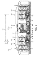
- the device 10 for inserting artificial grass strand parts in the ground comprises a frame 12 which is configured to support the various components of the device.
- the device has tracks 20 and the drive 22 to be able to move the device over the ground 11.
- the device may also be provided with wheels or a skid element to achieve the same goal.
- the device may also be provided with a connector for attaching the device to the front or rear of another vehicle, for example a tractor.
- the device has a central driving part 24 which contains the tracks and the drive.
- the device has a front injection part 25A and a rear injection part 25B.
- the device furthermore has a plurality of spools 14 with artificial grass strands wound thereon.
- the device may have more than 50 spools, in particular 70 to 100 spools. A larger or smaller number of spools is also possible.
- the device comprises two drums 16 (indicated in figure 1 with reference numerals 16A, 16B ) which are mounted in a rotating manner on the frame 12.
- the drums 16 rotate about respective, substantially horizontal rotation axes 51 (shafts) (see figure 4 ).
- the shafts are supported on two ends by the frame.
- the axes are perpendicular to the direction of movement as indicated by arrow 18.
- the drums are configured to receive a plurality of artificial grass strands which are unwound from the spools 14 and to rotate these artificial grass strands with the movement of the drum.
- the device has a front drum 16A and a rear drum 16B which are placed behind each other in order to be able to work with two drums simultaneously.
- the front drum 16A is placed in front of the central travelling part and the rear drum 16B is placed behind the central travelling part.
- the drums have a diameter between 60 cm and 150 cm.
- the spools 14 are divided into two groups 26A, 26B, i.e. a front group 26A which is associated with the front drum 16A, and a rear group 26B which is associated with the rear drum 16B.
- the spools are mounted rotatably on stands 28 which are attached to the frame.
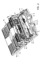
- the front injection part 25A comprises the front drum 16A and the front group of spools 26A. These are mounted on a front frame part 30A which is mounted on the central travelling part 24 via connectors 32.
- the rear injection part 25B comprises the rear drum 16B and the rear group of spools 26B mounted on a rear frame part 30B which is mounted on the central travelling part 24 via connectors 32. Both connectors have an upper fixing point 34 and a lower fixing point 35.
- the front frame part 30A comprises longitudinal members 41, cross members 42 and an upwardly extending part 43 which supports the drum 16A.
- the frame part 30A comprises further reinforcing members 44.
- the stands 28 and the spools 14 are not shown in these figures.
- the injection part 25A comprises a cutting device 36A which is positioned near the drum 16 and the function of which will be explained later.
- the injection part furthermore comprises a roller 45. This roller supports the frame.
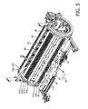
- the drum 16A comprises a plurality of clamps 50A, 50B, 50C, 50E, 50D and 50F. In total there are six clamps on each drum 16.
- the clamps are generally indicated with reference numeral 50.
- the drum may also have a different number of clamps, for example 4, 5, 7 or 8 clamps.
- the clamps are arranged around the rotation axis 51.
- the clamps rotate with the drum in the direction of arrow 52.
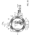
- the clamps 50 are placed at mutual intervals L1 of 30 - 50 cm, in particular 35 - 45 cm apart, more particularly at a distance of 38 - 42 cm apart.
- the distance L1 determines the length of the cut artificial grass strand parts 62.
- the length of the artificial grass strand part 62 is still greater than L1, because the guides 58 ensure that the path followed by the artificial grass strand part is not a straight line between two clamps but is formed by three parts:
- the parts 88A, 88B, 88C are shown in fig. 8 .
- the clamps For each artificial grass strand 60, the clamps hold an artificial grass strand part 62 clamped between a front clamp (in figure 4 , this is clamp 50A) and a rear clamp (in figure 5 , this is clamp 50B), viewed in the direction of rotation, and allow the artificial grass strand parts to rotate with the drum.
- the injection part 30A furthermore comprises a feed device for feeding the series of artificial grass strands from the spools to the drum.
- the feed device cannot be seen in figures 4 , 5 and 6 .
- the injection part 30A furthermore comprises a cutting device 36 for cutting the artificial grass strands, so that the clamped artificial grass strand parts 62 are cut loose from the rest of the respective artificial grass strand 60.
- the cutting device 36 has four rotating driven knives 55 which move to and fro in the direction of arrow 56 during rotation.
- the injection part 30A furthermore comprises an insertion device 70 which comprises a plurality of insertion pins 72 and at least one actuator 74, wherein the actuator 74 inserts the insertion pins 72 into the ground over a certain depth.
- the drum 16A is configured to rotate the series of artificial grass strand parts 62 to below the insertion device 70. By the rotation of the drum, the front clamp 50A - viewed in the direction of rotation - is moved underneath the insertion device.
- the insertion device 70 is configured to press the artificial grass strand parts 62, which are rotated to below the insertion device, into the ground.
- the insertion pins 72 of the insertion device 70 make contact at the underside of the drum with the artificial grass strand parts to be inserted.
- the insertion pins 72 are located in the drum and the drum 16A rotates around the insertion pins.
- the actuator 74 is outside the drum.
- the insertion pins 72 may be provided with an inverted V-shape at their bottom end, in order to be able to grip the artificial grass strand parts firmly.
- the drum is configured to tension at least two cut artificial grass strand parts 62 behind each other and bring these successively below the insertion device.
- Strand guides 58 are positioned between the clamps 50.
- the strand guides 58 are mounted on the drum and rotate with the drum.
- the cutting device 36 is mounted stationarily on the frame and is configured to cut the series of artificial grass strands.
- the drum inlet 90 where the artificial grass strands are fed into the drum, is located at the top half of the drum, more particularly at an angle ⁇ 1 of 120 - 270 degrees from the lowest point 89 of the drum. In figure 5 , it can be seen that ⁇ 1 is around 175 degrees.
- each clamp 50 is configured to clamp firmly at least 50 artificial grass strands, and for this has at least as many clamping shoes 82.
- Each clamp 50 may be configured to clamp at least 80 artificial grass strands. This is shown clearly in figure 5 .
- the clamping shoes 82 define grooves in which the artificial grass strands are placed.
- the artificial grass strands 60 and also the cut parts 62 are stationary relative to the drum during rotation of the drum.
- Each clamp defines at least 50 parallel tracks, and In an embodiment even at least 80 parallel tracks 83.
- the tracks lie next to each other and are separated from each other, wherein an artificial grass strand is fed into each track and wherein the clamp has a clamping shoe 82 for each track, for clamping the artificial grass strand in the track.
- Each clamp 50 comprises a front shoe 51A and a rear shoe 51 B, in particular a front shoe 51A and a rear shoe 51 B for each of the at least fifty clamping shoes 82, wherein a gap 57 is defined between the front shoes 51A and the rear shoes 51 B.
- the knives 55 of the cutting device are configured to make a cut through the artificial grass strands in the gap 57, so that the front shoe 51A holds a rear end of the cut artificial grass strand part 62 and the rear shoe holds a front end of the artificial grass strand 60.
- the clamps 50 are pre-tensioned by at least one spring force element 59.
- the clamps are connected together by a bar so that all clamps are activated and deactivated simultaneously.
- the artificial grass strands 60 are automatically clamped when placed in the clamp, without any further action being required.
- Each injection part of the device 10 has two clamp actuators 80 which deactivate the clamps 50, which hold the artificial grass strand parts 62 to be inserted, prior to insertion of the artificial grass strand parts by the insertion device.
- the clamp actuators 80 are arranged stationarily and are mounted on the frame, in particular next to the drum. It is however also possible to mount the clamp actuators 80 on the drum and allow them to rotate with the drum. In this case, for each clamp 50, a clamp deactivation device 80 is provided.
- the clamp actuators 80 are essentially deactivating actuators, i.e. they release the clamps 50 which are pre-tensioned by the spring device 59, against the force of the pretension by the spring device 59.
- the clamp actuators 80 are preferably hydraulic.
- the device has a presser element 84 and one or more presser actuators 86 (see also figure 2 ).
- the artificial grass strands are guided below the presser element 84.
- the presser element 84 has a series of continuous holes 85. Through these the insertion pins 72 are pressed into the ground. It is also possible that a number of through holes 85 are joined together into slots.
- the artificial grass strand parts can slide relative to the presser element.
- Each continuous hole 85 for an insertion pin opens at an artificial grass strand part during operation.
- the underside of the drum is at a distance of 5 - 30 cm, in particular at a distance of 10 - 20 cm, above the ground.
- the cutting device is situated at a distance L2 from the insertion device 70 which is greater than the distance L1 between two successive clamps, so that the artificial grass strands are cut through before they are positioned below the insertion device.
- L2 is here measured along the path which is defined by the clamps 50 and the guides 58.
- the method for inserting artificial grass strand parts in the ground 11 comprises the following steps.
- the device 10 is moved over the ground 11 to a location and the device is stopped at this location.
- a series of artificial grass strands 60 is fed into the drum and clamped by a front clamp 50A.
- the drum rotates through a cycle angle ⁇ of 60 degrees to a next position, in which movement the front clamp 50A draws the series of artificial grass strands off the spools.
- the front clamp 50A is in front of the cutting device 36.
- a following clamp 50B grips the series of artificial grass strands. This is the situation shown in figure 4 .
- the drum 16 then rotates again through a cycle angle of 60° to a next position.
- the clamp 50A is now obliquely below the insertion device 70.
- the clamp 50B is in front of the cutting device.
- a following clamp 50C grips the artificial grass strands 60 and holds them firmly.
- a second series of artificial grass strands 62' is clamped.
- the rotating knives 55 are moved in the direction of arrow 91 into the gap between the front shoe 51A and the rear shoe 51 B of clamp 50B. This takes place by actuators 92 (which are indicated in figure 2 ).
- the knives 55 then cut through all artificial grass strands by moving forward and back along arrow 56 (see fig. 5 ) during rotation.
- the artificial grass strand parts 62 are now separate from the rest of the artificial grass strands 60 and are held by the rear shoe 51 B of clamp 50A and the front shoe 51A of clamp 50B.
- the presser element 84 (see fig. 3 ) is then pressed against the ground so that the artificial grass strand parts cannot shift sideways.
- the artificial grass strand parts 62 can however shift in their length direction relative to the presser device.
- the insertion device 70 is then activated and the insertion pins 72 are pressed into the ground.
- Each insertion pin carries with it an artificial grass strand part 62.
- the artificial grass strand parts 62 are folded in half during insertion, with a U bend at the bottom end.
- the device 10 is moved over a cycle distance L4 (see fig. 1 ) to a following position on the hybrid grass surface to be created, and stopped there.
- the cycle distance L4 over which the device is moved is of the order of 2 - 6 cm, i.e. relatively small. Other distances may also be chosen.
- the mutual spacing L3 (see fig.1 ) between the two drums 16A, 16B can be set by means of actuators 200 or other adjustment means. In practice, it has proved useful to allow the front and rear drum to insert strands out of phase.
- the rear drum 16B inserts its strands in the middle between two successive rows inserted by the front drum 16A.
- the front drum for example inserts strands every 4 cm, and the rear drum inserts precisely in-between so that the overall insertion gap is 2 cm.
- the distance L3 is fixed and is a multiple of the cycle distance L4, whereby it is difficult or impossible to work continuously.
- the rear drum would insert strands at precisely the same point as the front drum. This is prevented by only allowing the machine to rotate over a distance L3, and then to advance the machine without insertion over a distance L3. Then it may again insert strands after a distance L3. This pattern may be repeated. It is however an awkward way of inserting strands.
- the drum 16 is rotated through a cycle angle to a following position.
- the rotation of the drum and the travelling to a new position may take place simultaneously for faster working.
- the series of artificial grass strand parts is positioned in the insertion position below the insertion device by the rotation of the drum. A new series of artificial grass strand parts is clamped.
- the artificial grass strand parts 62 are typically inserted in the ground over a distance of 18 cm and protrude 2 cm above the ground. Because the artificial grass strand parts 62 are folded in half, the total length required for each artificial grass strand part is 40 cm. Thus the mutual spacing, measured along the path followed by the artificial grass strands, between the clamps 50A, 50B, 50C, 50D, 50E and 50F is 30 - 50 cm, in particular 35 - 45 cm, more particularly 38 - 42 cm.
- the insertion depth H1 may to some extent be varied, i.e. may amount to 15 - 20 cm, and a length (L1) of the artificial grass tufts above the ground may be between 1 - 4 cm.
- the device performs a cycle, wherein the cycle comprises a rotation period and stationary period wherein:
- the clamps 50 perform a rotating movement around the insertion device.
- the clamps do not perform any reciprocating movement as in the machine according to the prior art.
- the artificial grass strands are cut before they are positioned below the insertion device. This too is different from the prior art, where the artificial grass strand parts are first brought below the insertion device and only then cut through.
- the rear drum 16B rotates with the bottom part against the transport direction of the device 10.
- the front drum 16A rotates with the bottom part with the transport direction 18 of the device 10.
- the device may have a cycle time of less than 8 seconds, in particular less than 6 seconds.
- the clamps define at least 50 parallel tracks, in particular more than 70 parallel tracks, even more particularly more than 80 parallel tracks, and the same number of pins.
- the tracks are separate from each other. This is different from the machine according to EP1384817 where a drum defines a helical pattern.
- the strand In EP1384817 , the strand must first be arranged over the entire helix, which takes a long time.
- at least 50 strands can be arranged in the tracks simultaneously.
- the artificial grass strands 60 usually comprise several fibers, in particular 5 to 8 fibers, more particularly 5 to 6 fibers.
Priority Applications (2)
| Application Number | Priority Date | Filing Date | Title |
|---|---|---|---|
| EP16203621.4A EP3165675B1 (de) | 2015-01-26 | 2015-08-14 | Vorrichtung zum einsetzen von kunstrasenfasern in den boden |
| PL15181163T PL3029199T3 (pl) | 2015-01-26 | 2015-08-14 | Urządzenie do wprowadzania źdźbeł sztucznej trawy do podłoża |
Applications Claiming Priority (1)
| Application Number | Priority Date | Filing Date | Title |
|---|---|---|---|
| NL2014189A NL2014189B1 (nl) | 2015-01-26 | 2015-01-26 | Inrichting voor het in de grond aanbrengen van kunstgrassprieten. |
Related Child Applications (1)
| Application Number | Title | Priority Date | Filing Date |
|---|---|---|---|
| EP16203621.4A Division EP3165675B1 (de) | 2015-01-26 | 2015-08-14 | Vorrichtung zum einsetzen von kunstrasenfasern in den boden |
Publications (2)
| Publication Number | Publication Date |
|---|---|
| EP3029199A1 true EP3029199A1 (de) | 2016-06-08 |
| EP3029199B1 EP3029199B1 (de) | 2016-12-14 |
Family
ID=52682882
Family Applications (2)
| Application Number | Title | Priority Date | Filing Date |
|---|---|---|---|
| EP15181163.5A Active EP3029199B1 (de) | 2015-01-26 | 2015-08-14 | Vorrichtung zum einsetzen von kunstrasenfasern in den boden |
| EP16203621.4A Active EP3165675B1 (de) | 2015-01-26 | 2015-08-14 | Vorrichtung zum einsetzen von kunstrasenfasern in den boden |
Family Applications After (1)
| Application Number | Title | Priority Date | Filing Date |
|---|---|---|---|
| EP16203621.4A Active EP3165675B1 (de) | 2015-01-26 | 2015-08-14 | Vorrichtung zum einsetzen von kunstrasenfasern in den boden |
Country Status (19)
| Country | Link |
|---|---|
| US (3) | US20190127926A1 (de) |
| EP (2) | EP3029199B1 (de) |
| JP (1) | JP6626881B2 (de) |
| KR (1) | KR20170033877A (de) |
| CN (1) | CN106661850B (de) |
| AU (3) | AU2016212811B2 (de) |
| CA (1) | CA2954405C (de) |
| DE (3) | DE16203621T1 (de) |
| DK (1) | DK3029199T3 (de) |
| ES (1) | ES2616359T3 (de) |
| HK (1) | HK1223990A1 (de) |
| HU (1) | HUE033221T2 (de) |
| MA (1) | MA39742A (de) |
| NL (1) | NL2014189B1 (de) |
| NZ (1) | NZ728144A (de) |
| PL (1) | PL3029199T3 (de) |
| RU (1) | RU2637671C9 (de) |
| SG (1) | SG11201700106SA (de) |
| WO (1) | WO2016122312A1 (de) |
Cited By (3)
| Publication number | Priority date | Publication date | Assignee | Title |
|---|---|---|---|---|
| DE102015112329A1 (de) * | 2015-07-28 | 2017-02-02 | Smg Sportplatzmaschinenbau Gmbh | Taftmaschine |
| WO2018109137A1 (de) * | 2016-12-14 | 2018-06-21 | Smg Sportplatzmaschinenbau Gmbh | Tafteinheit, taftmaschine, und verfahren zum einsetzen von garnabschnitten in einen untergrund |
| NL2022946B1 (nl) * | 2019-04-15 | 2020-10-22 | Tarkett Sports B V | Inrichting voor het in de grond aanbrengen van kunststof vezels |
Families Citing this family (14)
| Publication number | Priority date | Publication date | Assignee | Title |
|---|---|---|---|---|
| NL2016654B1 (nl) | 2016-04-21 | 2017-11-15 | Desso Sports B V | Inrichting voor het in de grond aanbrengen van kunststof vezels. |
| WO2018074930A1 (en) | 2016-10-21 | 2018-04-26 | Desso Sports B.V. | Method and device for introducing thread-like fibres into the ground, combination of a substrate member and a collection of thread-like fibres, and device for introducing thread-like fibres into the ground |
| WO2019027317A1 (en) | 2017-08-03 | 2019-02-07 | Sisgrass B.V. | DEVICE AND METHOD FOR INSERTING PARTS OF ARTIFICIAL GRASS STRANDS IN THE SOIL |
| CN108738861B (zh) * | 2018-07-26 | 2023-10-24 | 北京天仁科技发展有限公司 | 一种混合草坪建植机 |
| CN108834772B (zh) * | 2018-07-26 | 2023-10-24 | 北京天仁科技发展有限公司 | 一种基于混合草坪建植机的插针过载保护装置及其建植机 |
| CN108834770A (zh) * | 2018-07-26 | 2018-11-20 | 北京天仁科技发展有限公司 | 一种基于混合草坪建植机的循环式拉草辊筒及其建植机 |
| CN108755361A (zh) * | 2018-07-26 | 2018-11-06 | 北京天仁科技发展有限公司 | 一种基于混合草坪建植机的夹草管装置及其建植机 |
| DE202018107291U1 (de) * | 2018-12-19 | 2020-03-20 | Smg Sportplatzmaschinenbau Gmbh | Tafteinheit und Taftmaschine |
| CN111305015B (zh) * | 2020-03-10 | 2024-04-30 | 闫宝生 | 一种人工海绵体草坪扦插机 |
| CN111517162B (zh) * | 2020-04-30 | 2021-08-10 | 北京天仁科技发展有限公司 | 应用于混合草坪植丝机的压丝装置 |
| CN111519493B (zh) * | 2020-04-30 | 2021-08-03 | 北京天仁科技发展有限公司 | 一种草坪植丝机 |
| CN111485339B (zh) * | 2020-04-30 | 2021-02-02 | 北京天仁科技发展有限公司 | 一种草坪人工植丝机的植丝针机构 |
| EP4326933A1 (de) | 2021-04-19 | 2024-02-28 | Sisgrass B.V. | Injektion mit variabler graslänge |
| NL2028838B1 (en) | 2021-07-26 | 2023-01-31 | Sisgrass B V | Variable grass-length injection |
Citations (3)
| Publication number | Priority date | Publication date | Assignee | Title |
|---|---|---|---|---|
| WO1993008332A1 (en) * | 1991-10-14 | 1993-04-29 | Tapijtfabriek H. Desseaux N.V. | A device for inserting elongated artificial grass fibres into the ground |
| WO2001079611A1 (en) | 2000-04-19 | 2001-10-25 | Tapijtfabriek H. Desseaux N.V. | Method for inserting synthetic fibres into a surface, as well as a device for carrying out the same |
| EP1384817A1 (de) | 2002-07-23 | 2004-01-28 | Tapijtfabriek H. Desseaux N.V. | Vorrichtung und Verfahren zum Einbringen von langen Fasern in eine Oberfläche |
Family Cites Families (8)
| Publication number | Priority date | Publication date | Assignee | Title |
|---|---|---|---|---|
| US3515079A (en) * | 1967-09-18 | 1970-06-02 | James K Ware Jr | Sprig planter |
| SU1261987A1 (ru) * | 1985-01-03 | 1986-10-07 | 3-Й Государственный Ордена Трудового Красного Знамени Подшипниковый Завод | Машина дл изготовлени изделий с прошивным ворсом |
| CA2206295A1 (fr) * | 1997-06-09 | 1998-12-09 | Alain Lemieux | Gazon synthetique, de composition specifique, faite par un procede au jet de sable, jumele a une base en polypropylene servant de coussin d'absorption, ainsi qu'un procede de traitement au jet de sable de cette surface de gazon synthetique |
| NL1007279C2 (nl) * | 1997-10-15 | 1999-04-19 | Desseaux H Tapijtfab | Inrichting voor het in de grond inbrengen van kunstgrassprieten. |
| US7824133B1 (en) * | 2005-03-22 | 2010-11-02 | Joseph Lazaro | Artificial ground cover and system of installation |
| CN101619560B (zh) * | 2006-09-22 | 2011-05-18 | 毕国明 | 在自然土地上铺栽和养护人造草坪的设备 |
| US20120263891A1 (en) * | 2011-04-18 | 2012-10-18 | Tarkett Inc. | Repairing synthetic turf field and method for revitalizing the same |
| DE102015112329A1 (de) * | 2015-07-28 | 2017-02-02 | Smg Sportplatzmaschinenbau Gmbh | Taftmaschine |
-
1919
- 1919-10-31 US US16/176,092 patent/US20190127926A1/en not_active Abandoned
-
2015
- 2015-01-26 NL NL2014189A patent/NL2014189B1/nl active
- 2015-08-13 MA MA039742A patent/MA39742A/fr unknown
- 2015-08-14 DK DK15181163.5T patent/DK3029199T3/en active
- 2015-08-14 DE DE16203621.4T patent/DE16203621T1/de active Pending
- 2015-08-14 EP EP15181163.5A patent/EP3029199B1/de active Active
- 2015-08-14 EP EP16203621.4A patent/EP3165675B1/de active Active
- 2015-08-14 HU HUE15181163A patent/HUE033221T2/hu unknown
- 2015-08-14 ES ES15181163.5T patent/ES2616359T3/es active Active
- 2015-08-14 PL PL15181163T patent/PL3029199T3/pl unknown
- 2015-09-01 US US14/842,354 patent/US9683335B2/en active Active
-
2016
- 2016-01-19 JP JP2017507442A patent/JP6626881B2/ja active Active
- 2016-01-19 AU AU2016212811A patent/AU2016212811B2/en active Active
- 2016-01-19 NZ NZ728144A patent/NZ728144A/en unknown
- 2016-01-19 DE DE202016102177.4U patent/DE202016102177U1/de active Active
- 2016-01-19 CN CN201680002205.0A patent/CN106661850B/zh active Active
- 2016-01-19 KR KR1020177004524A patent/KR20170033877A/ko not_active Application Discontinuation
- 2016-01-19 DE DE202016104972.5U patent/DE202016104972U1/de active Active
- 2016-01-19 CA CA2954405A patent/CA2954405C/en active Active
- 2016-01-19 SG SG11201700106SA patent/SG11201700106SA/en unknown
- 2016-01-19 WO PCT/NL2016/050043 patent/WO2016122312A1/en active Application Filing
- 2016-01-19 RU RU2017100499A patent/RU2637671C9/ru active
- 2016-10-25 HK HK16112223.6A patent/HK1223990A1/zh unknown
-
2017
- 2017-03-08 AU AU2017100275A patent/AU2017100275A4/en not_active Expired
- 2017-05-12 AU AU2017203199A patent/AU2017203199A1/en not_active Abandoned
- 2017-05-19 US US15/600,246 patent/US10151070B2/en active Active
Patent Citations (3)
| Publication number | Priority date | Publication date | Assignee | Title |
|---|---|---|---|---|
| WO1993008332A1 (en) * | 1991-10-14 | 1993-04-29 | Tapijtfabriek H. Desseaux N.V. | A device for inserting elongated artificial grass fibres into the ground |
| WO2001079611A1 (en) | 2000-04-19 | 2001-10-25 | Tapijtfabriek H. Desseaux N.V. | Method for inserting synthetic fibres into a surface, as well as a device for carrying out the same |
| EP1384817A1 (de) | 2002-07-23 | 2004-01-28 | Tapijtfabriek H. Desseaux N.V. | Vorrichtung und Verfahren zum Einbringen von langen Fasern in eine Oberfläche |
Cited By (5)
| Publication number | Priority date | Publication date | Assignee | Title |
|---|---|---|---|---|
| DE102015112329A1 (de) * | 2015-07-28 | 2017-02-02 | Smg Sportplatzmaschinenbau Gmbh | Taftmaschine |
| WO2017017237A1 (de) * | 2015-07-28 | 2017-02-02 | Smg Sportplatzmaschinenbau Gmbh | Tuftmaschine |
| WO2018109137A1 (de) * | 2016-12-14 | 2018-06-21 | Smg Sportplatzmaschinenbau Gmbh | Tafteinheit, taftmaschine, und verfahren zum einsetzen von garnabschnitten in einen untergrund |
| NL2022946B1 (nl) * | 2019-04-15 | 2020-10-22 | Tarkett Sports B V | Inrichting voor het in de grond aanbrengen van kunststof vezels |
| WO2020214028A1 (en) | 2019-04-15 | 2020-10-22 | Tarkett Sports B.V. | Device for introducing plastic fibres into the ground |
Also Published As
Similar Documents
| Publication | Publication Date | Title |
|---|---|---|
| EP3029199B1 (de) | Vorrichtung zum einsetzen von kunstrasenfasern in den boden | |
| DE2531734C2 (de) | Fadenführung an maschenbildenden Maschinen mit umlaufenden Fadenführern | |
| DE102013204028A1 (de) | Verarbeitungsstation zum Anbringen eines Profilelements | |
| JP2007009560A (ja) | 人工芝の製造装置 | |
| DE60116289T2 (de) | Weben von teppichen | |
| CN108699905A (zh) | 用于采矿或挖掘隧道装备的网处理装置 | |
| EP1512784A1 (de) | Verfahren und Vorrichtung zum Vorlegen und Fixieren von bandförmigen Filamentscharen | |
| CN113330152B (zh) | 簇绒单元和簇绒机 | |
| DE60116089T2 (de) | Einheit zum Bilden von Tuftinggarnen und Webmaschine | |
| TW200526829A (en) | Direct winding type sample warper | |
| CN112043071B (zh) | 一种快插件植毛方法 | |
| CN112318392B (zh) | 一种稳定且高效的破鳞辊刷盘的穿丝方法 | |
| CN112353088B (zh) | 一种用于破鳞辊刷盘的穿丝机构 | |
| KR200203400Y1 (ko) | 고추묶음장치 | |
| DE554925C (de) | Verfahren und Webstuhl zur Herstellung von Florgeweben mit Chenilleeinschlag | |
| DE19538081A1 (de) | Vorrichtung und Verfahren zur Herstellung einer Webmaschenware | |
| AU2005218015A1 (en) | Carpet Making Machinery | |
| DE1199228B (de) | Vorrichtung zum Zufuehren des Heft-fadens in Fadenbuchheftmaschinen oder Fadenheftapparaten |
Legal Events
| Date | Code | Title | Description |
|---|---|---|---|
| PUAI | Public reference made under article 153(3) epc to a published international application that has entered the european phase |
Free format text: ORIGINAL CODE: 0009012 |
|
| 17P | Request for examination filed |
Effective date: 20150814 |
|
| AK | Designated contracting states |
Kind code of ref document: A1 Designated state(s): AL AT BE BG CH CY CZ DE DK EE ES FI FR GB GR HR HU IE IS IT LI LT LU LV MC MK MT NL NO PL PT RO RS SE SI SK SM TR |
|
| AX | Request for extension of the european patent |
Extension state: BA ME |
|
| GRAP | Despatch of communication of intention to grant a patent |
Free format text: ORIGINAL CODE: EPIDOSNIGR1 |
|
| INTG | Intention to grant announced |
Effective date: 20161006 |
|
| STAA | Information on the status of an ep patent application or granted ep patent |
Free format text: STATUS: GRANT OF PATENT IS INTENDED |
|
| GRAS | Grant fee paid |
Free format text: ORIGINAL CODE: EPIDOSNIGR3 |
|
| GRAA | (expected) grant |
Free format text: ORIGINAL CODE: 0009210 |
|
| STAA | Information on the status of an ep patent application or granted ep patent |
Free format text: STATUS: THE PATENT HAS BEEN GRANTED |
|
| RAV | Requested validation state of the european patent: fee paid |
Extension state: MA Effective date: 20161013 |
|
| AK | Designated contracting states |
Kind code of ref document: B1 Designated state(s): AL AT BE BG CH CY CZ DE DK EE ES FI FR GB GR HR HU IE IS IT LI LT LU LV MC MK MT NL NO PL PT RO RS SE SI SK SM TR |
|
| REG | Reference to a national code |
Ref country code: GB Ref legal event code: FG4D |
|
| REG | Reference to a national code |
Ref country code: CH Ref legal event code: EP |
|
| REG | Reference to a national code |
Ref country code: IE Ref legal event code: FG4D |
|
| REG | Reference to a national code |
Ref country code: AT Ref legal event code: REF Ref document number: 853697 Country of ref document: AT Kind code of ref document: T Effective date: 20170115 |
|
| REG | Reference to a national code |
Ref country code: DE Ref legal event code: R096 Ref document number: 602015000994 Country of ref document: DE |
|
| REG | Reference to a national code |
Ref country code: NL Ref legal event code: FP |
|
| REG | Reference to a national code |
Ref country code: DK Ref legal event code: T3 Effective date: 20170221 |
|
| PG25 | Lapsed in a contracting state [announced via postgrant information from national office to epo] |
Ref country code: LV Free format text: LAPSE BECAUSE OF FAILURE TO SUBMIT A TRANSLATION OF THE DESCRIPTION OR TO PAY THE FEE WITHIN THE PRESCRIBED TIME-LIMIT Effective date: 20161214 |
|
| REG | Reference to a national code |
Ref country code: SE Ref legal event code: TRGR |
|
| REG | Reference to a national code |
Ref country code: LT Ref legal event code: MG4D |
|
| PG25 | Lapsed in a contracting state [announced via postgrant information from national office to epo] |
Ref country code: LT Free format text: LAPSE BECAUSE OF FAILURE TO SUBMIT A TRANSLATION OF THE DESCRIPTION OR TO PAY THE FEE WITHIN THE PRESCRIBED TIME-LIMIT Effective date: 20161214 Ref country code: NO Free format text: LAPSE BECAUSE OF FAILURE TO SUBMIT A TRANSLATION OF THE DESCRIPTION OR TO PAY THE FEE WITHIN THE PRESCRIBED TIME-LIMIT Effective date: 20170314 Ref country code: GR Free format text: LAPSE BECAUSE OF FAILURE TO SUBMIT A TRANSLATION OF THE DESCRIPTION OR TO PAY THE FEE WITHIN THE PRESCRIBED TIME-LIMIT Effective date: 20170315 |
|
| PG25 | Lapsed in a contracting state [announced via postgrant information from national office to epo] |
Ref country code: RS Free format text: LAPSE BECAUSE OF FAILURE TO SUBMIT A TRANSLATION OF THE DESCRIPTION OR TO PAY THE FEE WITHIN THE PRESCRIBED TIME-LIMIT Effective date: 20161214 Ref country code: FI Free format text: LAPSE BECAUSE OF FAILURE TO SUBMIT A TRANSLATION OF THE DESCRIPTION OR TO PAY THE FEE WITHIN THE PRESCRIBED TIME-LIMIT Effective date: 20161214 Ref country code: HR Free format text: LAPSE BECAUSE OF FAILURE TO SUBMIT A TRANSLATION OF THE DESCRIPTION OR TO PAY THE FEE WITHIN THE PRESCRIBED TIME-LIMIT Effective date: 20161214 |
|
| REG | Reference to a national code |
Ref country code: ES Ref legal event code: FG2A Ref document number: 2616359 Country of ref document: ES Kind code of ref document: T3 Effective date: 20170612 |
|
| PG25 | Lapsed in a contracting state [announced via postgrant information from national office to epo] |
Ref country code: IS Free format text: LAPSE BECAUSE OF FAILURE TO SUBMIT A TRANSLATION OF THE DESCRIPTION OR TO PAY THE FEE WITHIN THE PRESCRIBED TIME-LIMIT Effective date: 20170414 Ref country code: EE Free format text: LAPSE BECAUSE OF FAILURE TO SUBMIT A TRANSLATION OF THE DESCRIPTION OR TO PAY THE FEE WITHIN THE PRESCRIBED TIME-LIMIT Effective date: 20161214 Ref country code: RO Free format text: LAPSE BECAUSE OF FAILURE TO SUBMIT A TRANSLATION OF THE DESCRIPTION OR TO PAY THE FEE WITHIN THE PRESCRIBED TIME-LIMIT Effective date: 20161214 Ref country code: SK Free format text: LAPSE BECAUSE OF FAILURE TO SUBMIT A TRANSLATION OF THE DESCRIPTION OR TO PAY THE FEE WITHIN THE PRESCRIBED TIME-LIMIT Effective date: 20161214 |
|
| REG | Reference to a national code |
Ref country code: HK Ref legal event code: DE Ref document number: 1223990 Country of ref document: HK |
|
| REG | Reference to a national code |
Ref country code: FR Ref legal event code: PLFP Year of fee payment: 3 |
|
| PG25 | Lapsed in a contracting state [announced via postgrant information from national office to epo] |
Ref country code: BG Free format text: LAPSE BECAUSE OF FAILURE TO SUBMIT A TRANSLATION OF THE DESCRIPTION OR TO PAY THE FEE WITHIN THE PRESCRIBED TIME-LIMIT Effective date: 20170314 Ref country code: SM Free format text: LAPSE BECAUSE OF FAILURE TO SUBMIT A TRANSLATION OF THE DESCRIPTION OR TO PAY THE FEE WITHIN THE PRESCRIBED TIME-LIMIT Effective date: 20161214 Ref country code: PT Free format text: LAPSE BECAUSE OF FAILURE TO SUBMIT A TRANSLATION OF THE DESCRIPTION OR TO PAY THE FEE WITHIN THE PRESCRIBED TIME-LIMIT Effective date: 20170414 |
|
| REG | Reference to a national code |
Ref country code: DE Ref legal event code: R026 Ref document number: 602015000994 Country of ref document: DE |
|
| PLBI | Opposition filed |
Free format text: ORIGINAL CODE: 0009260 |
|
| PLAX | Notice of opposition and request to file observation + time limit sent |
Free format text: ORIGINAL CODE: EPIDOSNOBS2 |
|
| 26 | Opposition filed |
Opponent name: HEILER GMBH & CO. KG Effective date: 20170912 |
|
| REG | Reference to a national code |
Ref country code: HU Ref legal event code: AG4A Ref document number: E033221 Country of ref document: HU |
|
| PLBB | Reply of patent proprietor to notice(s) of opposition received |
Free format text: ORIGINAL CODE: EPIDOSNOBS3 |
|
| PG25 | Lapsed in a contracting state [announced via postgrant information from national office to epo] |
Ref country code: SI Free format text: LAPSE BECAUSE OF FAILURE TO SUBMIT A TRANSLATION OF THE DESCRIPTION OR TO PAY THE FEE WITHIN THE PRESCRIBED TIME-LIMIT Effective date: 20161214 |
|
| RAP2 | Party data changed (patent owner data changed or rights of a patent transferred) |
Owner name: SISGRASS B.V. |
|
| PLAB | Opposition data, opponent's data or that of the opponent's representative modified |
Free format text: ORIGINAL CODE: 0009299OPPO |
|
| PG25 | Lapsed in a contracting state [announced via postgrant information from national office to epo] |
Ref country code: MC Free format text: LAPSE BECAUSE OF FAILURE TO SUBMIT A TRANSLATION OF THE DESCRIPTION OR TO PAY THE FEE WITHIN THE PRESCRIBED TIME-LIMIT Effective date: 20161214 |
|
| REG | Reference to a national code |
Ref country code: HK Ref legal event code: GR Ref document number: 1223990 Country of ref document: HK |
|
| R26 | Opposition filed (corrected) |
Opponent name: HEILER GMBH & CO. KG Effective date: 20170912 |
|
| PG25 | Lapsed in a contracting state [announced via postgrant information from national office to epo] |
Ref country code: LU Free format text: LAPSE BECAUSE OF NON-PAYMENT OF DUE FEES Effective date: 20170814 |
|
| REG | Reference to a national code |
Ref country code: FR Ref legal event code: PLFP Year of fee payment: 4 |
|
| PG25 | Lapsed in a contracting state [announced via postgrant information from national office to epo] |
Ref country code: MT Free format text: LAPSE BECAUSE OF NON-PAYMENT OF DUE FEES Effective date: 20170814 |
|
| REG | Reference to a national code |
Ref country code: CH Ref legal event code: PL |
|
| PG25 | Lapsed in a contracting state [announced via postgrant information from national office to epo] |
Ref country code: CH Free format text: LAPSE BECAUSE OF NON-PAYMENT OF DUE FEES Effective date: 20180831 Ref country code: LI Free format text: LAPSE BECAUSE OF NON-PAYMENT OF DUE FEES Effective date: 20180831 |
|
| VS25 | Lapsed in a validation state [announced via postgrant information from nat. office to epo] |
Ref country code: MA Free format text: LAPSE BECAUSE OF FAILURE TO SUBMIT A TRANSLATION OF THE DESCRIPTION OR TO PAY THE FEE WITHIN THE PRESCRIBED TIME-LIMIT; INVALID AB INITIO Effective date: 20150814 |
|
| REG | Reference to a national code |
Ref country code: AT Ref legal event code: UEP Ref document number: 853697 Country of ref document: AT Kind code of ref document: T Effective date: 20161214 |
|
| REG | Reference to a national code |
Ref country code: DE Ref legal event code: R082 Ref document number: 602015000994 Country of ref document: DE Ref country code: DE Ref legal event code: R082 Ref document number: 602015000994 Country of ref document: DE Representative=s name: PATENTANWAELTE BAUER VORBERG KAYSER PARTNERSCH, DE |
|
| PG25 | Lapsed in a contracting state [announced via postgrant information from national office to epo] |
Ref country code: CY Free format text: LAPSE BECAUSE OF FAILURE TO SUBMIT A TRANSLATION OF THE DESCRIPTION OR TO PAY THE FEE WITHIN THE PRESCRIBED TIME-LIMIT Effective date: 20161214 |
|
| PG25 | Lapsed in a contracting state [announced via postgrant information from national office to epo] |
Ref country code: MK Free format text: LAPSE BECAUSE OF FAILURE TO SUBMIT A TRANSLATION OF THE DESCRIPTION OR TO PAY THE FEE WITHIN THE PRESCRIBED TIME-LIMIT Effective date: 20161214 |
|
| REG | Reference to a national code |
Ref country code: DE Ref legal event code: R082 Ref document number: 602015000994 Country of ref document: DE Representative=s name: PATENTANWAELTE BAUER VORBERG KAYSER PARTNERSCH, DE |
|
| PLBP | Opposition withdrawn |
Free format text: ORIGINAL CODE: 0009264 |
|
| PLBD | Termination of opposition procedure: decision despatched |
Free format text: ORIGINAL CODE: EPIDOSNOPC1 |
|
| REG | Reference to a national code |
Ref country code: DE Ref legal event code: R100 Ref document number: 602015000994 Country of ref document: DE |
|
| PG25 | Lapsed in a contracting state [announced via postgrant information from national office to epo] |
Ref country code: AL Free format text: LAPSE BECAUSE OF FAILURE TO SUBMIT A TRANSLATION OF THE DESCRIPTION OR TO PAY THE FEE WITHIN THE PRESCRIBED TIME-LIMIT Effective date: 20161214 |
|
| PLBM | Termination of opposition procedure: date of legal effect published |
Free format text: ORIGINAL CODE: 0009276 |
|
| STAA | Information on the status of an ep patent application or granted ep patent |
Free format text: STATUS: OPPOSITION PROCEDURE CLOSED |
|
| 27C | Opposition proceedings terminated |
Effective date: 20200626 |
|
| P01 | Opt-out of the competence of the unified patent court (upc) registered |
Effective date: 20230426 |
|
| PGFP | Annual fee paid to national office [announced via postgrant information from national office to epo] |
Ref country code: NL Payment date: 20230825 Year of fee payment: 9 |
|
| PGFP | Annual fee paid to national office [announced via postgrant information from national office to epo] |
Ref country code: TR Payment date: 20230809 Year of fee payment: 9 Ref country code: IT Payment date: 20230831 Year of fee payment: 9 Ref country code: IE Payment date: 20230821 Year of fee payment: 9 Ref country code: GB Payment date: 20230824 Year of fee payment: 9 Ref country code: ES Payment date: 20230918 Year of fee payment: 9 Ref country code: CZ Payment date: 20230802 Year of fee payment: 9 Ref country code: AT Payment date: 20230818 Year of fee payment: 9 |
|
| PGFP | Annual fee paid to national office [announced via postgrant information from national office to epo] |
Ref country code: SE Payment date: 20230823 Year of fee payment: 9 Ref country code: PL Payment date: 20230804 Year of fee payment: 9 Ref country code: HU Payment date: 20230811 Year of fee payment: 9 Ref country code: FR Payment date: 20230822 Year of fee payment: 9 Ref country code: DK Payment date: 20230823 Year of fee payment: 9 Ref country code: DE Payment date: 20230822 Year of fee payment: 9 Ref country code: BE Payment date: 20230825 Year of fee payment: 9 |