EP3028982B1 - Connection system for crane boom segments - Google Patents
Connection system for crane boom segments Download PDFInfo
- Publication number
- EP3028982B1 EP3028982B1 EP15200561.7A EP15200561A EP3028982B1 EP 3028982 B1 EP3028982 B1 EP 3028982B1 EP 15200561 A EP15200561 A EP 15200561A EP 3028982 B1 EP3028982 B1 EP 3028982B1
- Authority
- EP
- European Patent Office
- Prior art keywords
- connector
- boom
- connectors
- extensions
- segments
- Prior art date
- Legal status (The legal status is an assumption and is not a legal conclusion. Google has not performed a legal analysis and makes no representation as to the accuracy of the status listed.)
- Active
Links
- 230000013011 mating Effects 0.000 claims description 9
- 230000007935 neutral effect Effects 0.000 description 7
- 238000003780 insertion Methods 0.000 description 4
- 230000037431 insertion Effects 0.000 description 4
- 238000000034 method Methods 0.000 description 4
- 230000008901 benefit Effects 0.000 description 3
- 238000005266 casting Methods 0.000 description 2
- 238000003754 machining Methods 0.000 description 2
- 238000004519 manufacturing process Methods 0.000 description 2
- 229910000831 Steel Inorganic materials 0.000 description 1
- 238000005452 bending Methods 0.000 description 1
- 230000006835 compression Effects 0.000 description 1
- 238000007906 compression Methods 0.000 description 1
- 230000008878 coupling Effects 0.000 description 1
- 238000010168 coupling process Methods 0.000 description 1
- 238000005859 coupling reaction Methods 0.000 description 1
- 230000002452 interceptive effect Effects 0.000 description 1
- 238000005304 joining Methods 0.000 description 1
- 239000007787 solid Substances 0.000 description 1
- 239000010959 steel Substances 0.000 description 1
- 238000003466 welding Methods 0.000 description 1
Images


Classifications
-
- B—PERFORMING OPERATIONS; TRANSPORTING
- B66—HOISTING; LIFTING; HAULING
- B66C—CRANES; LOAD-ENGAGING ELEMENTS OR DEVICES FOR CRANES, CAPSTANS, WINCHES, OR TACKLES
- B66C23/00—Cranes comprising essentially a beam, boom, or triangular structure acting as a cantilever and mounted for translatory of swinging movements in vertical or horizontal planes or a combination of such movements, e.g. jib-cranes, derricks, tower cranes
- B66C23/62—Constructional features or details
- B66C23/64—Jibs
- B66C23/70—Jibs constructed of sections adapted to be assembled to form jibs or various lengths
-
- B—PERFORMING OPERATIONS; TRANSPORTING
- B66—HOISTING; LIFTING; HAULING
- B66C—CRANES; LOAD-ENGAGING ELEMENTS OR DEVICES FOR CRANES, CAPSTANS, WINCHES, OR TACKLES
- B66C23/00—Cranes comprising essentially a beam, boom, or triangular structure acting as a cantilever and mounted for translatory of swinging movements in vertical or horizontal planes or a combination of such movements, e.g. jib-cranes, derricks, tower cranes
-
- Y—GENERAL TAGGING OF NEW TECHNOLOGICAL DEVELOPMENTS; GENERAL TAGGING OF CROSS-SECTIONAL TECHNOLOGIES SPANNING OVER SEVERAL SECTIONS OF THE IPC; TECHNICAL SUBJECTS COVERED BY FORMER USPC CROSS-REFERENCE ART COLLECTIONS [XRACs] AND DIGESTS
- Y10—TECHNICAL SUBJECTS COVERED BY FORMER USPC
- Y10T—TECHNICAL SUBJECTS COVERED BY FORMER US CLASSIFICATION
- Y10T29/00—Metal working
- Y10T29/49—Method of mechanical manufacture
- Y10T29/49764—Method of mechanical manufacture with testing or indicating
- Y10T29/49778—Method of mechanical manufacture with testing or indicating with aligning, guiding, or instruction
- Y10T29/4978—Assisting assembly or disassembly
-
- Y—GENERAL TAGGING OF NEW TECHNOLOGICAL DEVELOPMENTS; GENERAL TAGGING OF CROSS-SECTIONAL TECHNOLOGIES SPANNING OVER SEVERAL SECTIONS OF THE IPC; TECHNICAL SUBJECTS COVERED BY FORMER USPC CROSS-REFERENCE ART COLLECTIONS [XRACs] AND DIGESTS
- Y10—TECHNICAL SUBJECTS COVERED BY FORMER USPC
- Y10T—TECHNICAL SUBJECTS COVERED BY FORMER US CLASSIFICATION
- Y10T29/00—Metal working
- Y10T29/49—Method of mechanical manufacture
- Y10T29/49826—Assembling or joining
- Y10T29/49947—Assembling or joining by applying separate fastener
-
- Y—GENERAL TAGGING OF NEW TECHNOLOGICAL DEVELOPMENTS; GENERAL TAGGING OF CROSS-SECTIONAL TECHNOLOGIES SPANNING OVER SEVERAL SECTIONS OF THE IPC; TECHNICAL SUBJECTS COVERED BY FORMER USPC CROSS-REFERENCE ART COLLECTIONS [XRACs] AND DIGESTS
- Y10—TECHNICAL SUBJECTS COVERED BY FORMER USPC
- Y10T—TECHNICAL SUBJECTS COVERED BY FORMER US CLASSIFICATION
- Y10T403/00—Joints and connections
- Y10T403/55—Member ends joined by inserted section
- Y10T403/553—Laterally inserted section
-
- Y—GENERAL TAGGING OF NEW TECHNOLOGICAL DEVELOPMENTS; GENERAL TAGGING OF CROSS-SECTIONAL TECHNOLOGIES SPANNING OVER SEVERAL SECTIONS OF THE IPC; TECHNICAL SUBJECTS COVERED BY FORMER USPC CROSS-REFERENCE ART COLLECTIONS [XRACs] AND DIGESTS
- Y10—TECHNICAL SUBJECTS COVERED BY FORMER USPC
- Y10T—TECHNICAL SUBJECTS COVERED BY FORMER US CLASSIFICATION
- Y10T403/00—Joints and connections
- Y10T403/70—Interfitted members
- Y10T403/7075—Interfitted members including discrete retainer
Definitions
- the present invention relates to lift cranes, and more particularly to connection systems for aligning sectional boom members for cranes and the like.
- Each of the sectional boom members is made of a plurality of chords and lacing or lattice elements.
- the terminal end portions of each chord are generally provided with connectors of one form or another to secure abutting boom segments together and to carry compressive loads between abutting chords.
- Typical connectors comprise male and female lugs secured by a pin carrying compressive loads in double shear.
- US 3,430,778 and US 2,975,910 show examples of mobile cranes with a jib or boom made up of two or more sections with pivot and locking means between adjacent sections.
- Other examples of connectors include those disclosed in EP Pat. No.
- FIG. 1 4 68 955 which illustrate a chord of a tower crane jib.
- the connectors on the chord include a shackle with holes to receive a pin or tenon.
- Yet another example of a connector include those disclosed in EP Pat. No. 0 533 323 , which illustrate a quick-connect system for boom members of a crane.
- the chords are configured to carry compressive loads.
- the connectors comprise compressive load bearing surfaces that are intersected by a line extending along the intersection of the vertical and horizontal neutral axes.
- An example 67m (220 foot) boom may be made of a 12m(40 foot) boom butt pivotally mounted to the crane upper works, a 9m(30 foot) boom top equipped with sheaves and rigging for lifting and supporting loads, with five sectional boom members in between: one 3m(10 feet) in length, one 6m(20 feet) in length and three 12m(40 feet) in length.
- Such an example boom has six boom segment connections. Typically each segment has four chords, and hence four connectors, making a total of 24 connectors that must be aligned and pinned to assemble the boom.
- a 12m(40 foot) long sectional boom member may weight over 2268kg(5,000 lbs).
- an assist crane is required to lift the boom member.
- One rigger usually then holds the suspended boom segment in general alignment while a second rigger uses a large hammer 4.5 or 6.8kg(10 or 15 lbs.) to manually drive the pin, which typically has a long taper, into position.
- the pins connecting the boom segments are generally used to carry the compressive loads between chords. As a result, the pins have a tight fit, further increasing the difficulty in assembling the boom. As such, it may take three men (a crane operator and two riggers) four or more hours to assemble the example 67m(220 foot) boom. Where the crane is moved frequently, the costs to assemble and disassemble the boom may exceed the cost to lift and position the load for which the crane is used.
- boom segments have connectors that include alignment surfaces and/or stop surfaces that allow the connectors to be easily aligned for insertion of the pin, and allow the boom segments to be initially connected and then rotated into a final position where the remainder of the connections between segments can be made.
- the present invention provides a mated connection between two sectional boom members as set out in claim 1, and a crane including such as a mated connection as set out in claim 4.
- the invention is a crane having a boom with a boom segment connection system, the crane having an upper works rotatably mounted on a lower works, the upper works including a load hoist winch, the boom comprising:
- a crane boom segment comprising:
- large sections of a lift crane boom can be assembled with a faster set-up time because the apertures through which the pins have to be driven are aligned when the connectors are brought into position and the alignment surfaces are brought into contact. Further, if the segments need to be connected from a non-aligned positioned, once one set of pins is in place, the sections can be pivoted into and will automatically stop in an aligned configuration with the apertures on the remaining connectors already lined up. With the preferred embodiment of the invention, this will be true whether the top or bottom pins are placed first.
- top For ease of reference, designation of “top,” “bottom,” “horizontal” and “vertical” are used herein and in the claims to refer to portions of a sectional boom in a position in which it would typically be assembled on or near the surface of the ground. These designations still apply although the boom may be raised to different angles, including a vertical position.
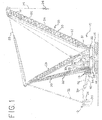
- the mobile lift crane 10, as shown in Fig. 1 includes lower works, also referred to as a carbody 12, and moveable ground engaging members in the form of crawlers 14 and 16.
- crawlers 14 and 16 there are of course two front crawlers 14 and two rear crawlers 16, only one each of which can be seen from the side view of Fig. 1 .
- the ground engaging members could be just one set of crawlers, one crawler on each side. Of course additional crawlers than those shown, or other ground engaging members such as tires, can be used.
- a rotating bed 20 is rotatably connected to the carbody 12 using a roller path, such that the rotating bed 20 can swing about an axis with respect to the ground engaging members 14, 16.
- the rotating bed supports a boom 50 pivotally mounted on a front portion of the rotating bed; a mast 28 mounted at its first end on the rotating bed; a backhitch 30 connected between the mast and a rear portion of the rotating bed; and a moveable counterweight unit 13 having counterweights 34 on a support member 33.
- the counterweights may be in the form of multiple stacks of individual counterweight members on the support member 33.
- Boom hoist rigging 25 between the top of mast 28 and boom 50 is used to control the boom angle and transfers load so that the counterweight can be used to balance a load lifted by the crane.
- a hoist line 24 extends from the boom 50, supporting a hook 26.
- the rotating bed 20 may also includes other elements commonly found on a mobile lift crane, such as an operator's cab and hoist drums for the rigging 25 and hoist line 24.
- the boom 50 may comprise a luffing jib pivotally mounted to the top of the main boom, or other boom configurations.
- the backhitch 30 is connected adjacent the top of the mast 28.
- the backhitch 30 may comprise a lattice member designed to cany both compression and tension loads as shown in Fig. 1 .
- the mast is held at a fixed angle with respect to the rotating bed during crane operations, such as a pick, move and set operation.
- the counterweight unit is moveable with respect to the rest of the rotating bed 20.
- the counterweight unit 13 is designed to be moved in and out with respect to the front of the crane.
- a tension member 32 connected adjacent the top of the mast supports the counterweight unit.
- a counterweight movement structure is connected between the rotating bed and the counterweight unit such that the counterweight unit may be moved to and held at a first position in front of the top of the mast, shown in solid lines in Fig. 1 , and moved to and held at a second position rearward of the top of the mast, shown in dotted lines in Fig. 1 .
- a hydraulic cylinder 36, pivot frame 40 and a rear arm 38 may be used to move the counterweight unit.
- the rear arm 38 actually has both left and right members, only one of which can be seen in Fig. 1
- the pivot frame has two side members, and the hydraulic cylinder comprises two cylinders that move in tandem.
- one larger hydraulic cylinder, or a rack and pinion structure, powered by preferably four hydraulic motors, could be used in place of the two hydraulic cylinders 36 to provide the linear actuation.
- the pivot frame could be made as a solid plate structure, and the two rear arms 38 could be replaced by one single structure.
- the pivot frame 40 is connected between the rotating bed 20 and hydraulic cylinder 36, and the rear arm 38 is connected between the pivot frame 40 and the counterweight unit.
- the hydraulic cylinder 36 is pivotally connected to the rotating bed 20 on a support frame which elevates the hydraulic cylinder 36 to a point so that the geometry of the cylinder 36, pivot frame 40 and rear arm 38 can move the counterweight through its entire range of motion. In this manner the cylinder 36 causes the rear arm 38 to move the counterweight unit when the cylinder is retracted and extended.
- Arms 38 have an angled portion 39 at the end that connects to the pivot frame 40. This allows the arms 38 to connect directly in line with the side members of pivot frame 40. The angled portion 39 prevents the arms 38 from interfering with the side members of the pivot frame the when the counterweight is in the position shown in solid lines in Fig. 1 .
- the boom 50 is made of several sectional members, including a boom butt 51, boom insert segments 52, 53, 54 and 55, which may vary in number and be of different lengths, and a boom top 56.
- the sectional boom members 51-56 typically are comprised of multiple chords. Two embodiments of connectors for connecting the boom segments are described below. Figs. 2-11 show a first embodiment, and Figs. 12-21 show a second embodiment.
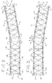
- Each boom segment 53 and 54 has a rectangular cross section with a chord at each corner.
- the segments 53 and 54 which are representative and may be considered as first and second boom segments, each have a longitudinal axis 41 ( Fig. 2 ), as well as first and second ends.
- the second end of the first segment 53 is coupled to the first end of the second segment 54.
- the chord members are made of steel with a circular, tubular cross section.
- a horizontal plane containing the longitudinal axis 41 can be considered to divide the boom segment into first and second longitudinal portions 67 and 68, with the two top chords 61 being present in the first portion 67 and the two bottom chords 63 being present in the second longitudinal portion of the boom segment 68.
- first and second longitudinal portions are identified for ease in explaining the invention.
- other configurations of boom segments are possible with a differing number of chords, and different ways of designating longitudinal portions of the boom segments are possible.
- Each chord member has a vertical neutral axis and a horizontal neutral axis. Compressive loads applied at the intersection of the vertical and horizontal neutral axes of a chord, or symmetrically about the horizontal and vertical neutral axes, will not induce bending moments within the chord.
- connectors that are used to connect boom segments together are mounted on the boom segments at the ends of the chords such that compressive loads transmitted through the connectors are symmetrical about the neutral axes of the chords.
- either the connectors on the top chords 61 can be connected first, or, as shown in Fig. 3 , the connectors on the bottom chords 63 can be connected first, while the boom segments are in a non-aligned configuration.
- the boom segments can then be pivoted and will automatically stop in a position where the additional connectors are aligned. It is also possible that the boom segments can be brought together with the longitudinal axes of the segments already lined up.
- the configuration of the connectors facilitates such an alignment and coupling of the boom segments, also as explained in more detail below.
- the connectors of the first embodiment are of two types, which may be referred to as first and second connectors, shown in detail in Figs. 8-11 .
- Each connector includes at least one extension having an aperture there through sized to receive a main pin, the extensions extending away from the boom segments to which they are attached, and the aperture having an axis perpendicular to that longitudinal axis.
- the extensions and apertures are positioned on their respective connectors such that when the second end of the boom segment is in an aligned position with and coupled to the first end of an identical boom segment, with connectors on the two boom segments coupled together, the extensions of the coupled connectors overlap one another and the apertures are aligned such that the main pin may be inserted through the apertures to secure the connector of the second end of the boom segment to the connector of the first end of an identical boom segment.
- Inventive boom segments used in the boom may differ in a number of respects, particularly in regard to features that have to do with crane assembly and operation other than the segment-to-segment connection system.)
- Preferably half of the connectors have a first number of extensions and half of the connectors have a second number of extensions, the second number being one greater than the first number, the connector on opposite ends of each chord having a different number of extensions from each other.
- the connector on the first end of the chord of the first longitudinal portion of the boom segment includes a first alignment surface and a stop surface.
- the connector on the second end of the chord of the first longitudinal portion of the boom segment includes a second alignment surface and a stop surface. In this embodiment, these surfaces are provided by different structures on the connectors. In the second embodiment it will be seen that the same structure that provides an alignment surface can also provide the stop surface.
- the first and second alignment surfaces cooperate such that when the first and second connectors are being brought together during boom assembly, the alignment surfaces urge the boom segments into a relative position such that the apertures through the extensions in the connectors are aligned sufficiently such that a tapered main pin can be inserted through the apertures of the extensions in the first and second mating connectors even if the boom segments are not axially aligned.
- the placement of the stop surface on the connectors are such that, when an identical boom segment is positioned such that a main pin can be inserted through the apertures in the extensions of the connectors of the remainder of the chords on the second longitudinal portion of the boom segments, the stop surfaces cooperate to align the apertures in the extensions of their respective connectors when the stop surfaces contact one another.
- Fig. 4 shows a mated connection between two sectional boom members 53 and 54.
- a first connecter 70 is affixed to the second end of a top chord 61 on a first sectional boom member 53.
- the connector 70 has two sets of three extensions 71a, 72a, and 73a, and 71b, 72b and 73b (best shown in Fig. 5 ), each having an aperture there through.
- the connector 70 also includes a first alignment surface in the form of a rounded outer surface 74 on the distal ends of each extension.
- the connector 70 further comprises a generally flat, compressive load bearing surface 78 that extends across the width of the connector and separates the two sets of extensions. In this embodiment, the load bearing surface 78 provides the stop surface for the connector.
- the second connector 80 is affixed to the first end of a top chord 61 on a second sectional boom member 54.
- the second connector 80 has two sets of two extensions 81a and 82a, and 81b and 82b, each having an aperture there through.
- the extensions 71, 72 and 73 of each set on connector 70 are interleaved with the respective set of extensions 81 and 82 on connector 80 when the connectors are coupled together, as seen in Fig. 4 .
- the connector 80 has a second alignment surface in the form of a pocket 84 adjacent the base of the outside portions of the extensions 81 and 82 matching the shape of the rounded outer surface 74. Drain holes 89 are provided in each connector 70, 80, as shown in Figs. 10 and 11 .
- the connector 80 also includes a generally flat, compressive load bearing surface 88 extending across the width of the connector. In this embodiment, the load bearing surfaces 78 and 88 provide the stop surfaces for the connector.
- the second alignment surface 84 and rounded first alignment surface 74 are in close proximity but not quite in contact with one another when the boom segments are in axial alignment, as shown in Fig. 4 .
- the connectors 70 and 80 can still be coupled to one another. In that instance, the first alignment surface 74 and second alignment surface 84 will contact one another as the boom sections are brought close to one another.
- the apertures in the extensions 71, 72, 73, 81 and 82 are in close enough alignment that a tapered main pin may be inserted through the apertures, meaning that it can start to be inserted, and the taper on the pin will cause the apertures to fully align as the pin is driven through the apertures.
- the compressive load bearing surface 78 will contact the compressive load bearing surface 88 to stop the pivoting at the point where the boom segments are aligned.
- the stop surfaces are positioned such that if one set of first and second connectors are coupled together by a pin through their apertures and the boom segments are in a non-aligned position, rotation of the boom segments about the pin through the apertures of the coupled connectors to the point where the stop surfaces of the additional connectors on the boom segments contact one another will bring the boom segments into alignment and the apertures on those additional connectors into alignment.
- another pin may be placed through the second set of extensions 71b, 72b, 73b, 81b and 82b.
- the bottom chords 63 are provided with connectors that have the same configuration as the connectors 70 and 80 on the top chords 61.
- the compressive load bearing surfaces of these lower connectors will come into contact with one another at the same time the compressive load bearing surfaces 78 and 88 on the top connectors come into contact with one another.
- the lower compressive load bearing surfaces thus also act as stop surfaces, aligning the apertures in the lower connectors.
- the connectors of the present invention allow sectional boom members to be connected and then rotate through a full 90° angle. Even if the boom segments are at an angle of 90° from their aligned position, first alignment surface 74 and second alignment surface 84 can be brought into contact with one another, making the apertures through the extensions close enough in alignment that a pin may be inserted. Of course after the pin is fully inserted, second alignment surface 84 and engagement member 74 do not contact each other. This assures that all loads are carried through the surface to surface contact of the compressive load bearing surfaces 78 and 88. Any tension loads can be carried by the pins.
- the compressive load bearing surfaces are preferably symmetrical about the horizontal and vertical neutral axes of the chord to which they are attached.
- the boom segments When the boom segments are assembled from a non-aligned arrangement as shown in either of Figs. 2 or 3 , the following steps will normally occur.
- the two boom segments will be brought together such that two connectors 70 on the first boom segment 53 mate with two respective connectors 80 on the second boom segment 54 to form two pairs of mated connectors, but the longitudinal axes 41 of the two segments are not aligned.
- the remaining connectors on each segment are not coupled.
- the mated connectors are fastened together with a pivoting connection as main pins are inserted though the apertures on one side of both pairs of mated connectors.
- the two segments 53 and 54 are then pivoted with respect to each other about the pivoting connection until the compressive load bearing surface 78 contacts the compressive load bearing surface 88.
- This arrangement allows the boom sections to "back bend” about either the top or bottom boom connection.
- the boom sections can be rotatably engaged with either the top or bottom pins inserted, then pivoted to a position where the segments are aligned and the opposite connectors can be pinned and the other pin inserted through the apertures on the inside of the top connectors.
- the boom segments may also be brought together in a generally aligned position, where the connectors on the top and bottom chords contact each other at roughly the same time. It will be appreciated that with the preferred geometry of the connectors, if the boom sections are not exactly aligned as they come together, the first alignment surface 74 will engage the second alignment surface 84 and urge the connectors to slide relative to one another until the engagement surface 74 is fully seated in pocket 84, thus urging the boom segments into the proper alignment such that when the engagement member and second alignment surface on both the upper and lower sets of connectors are fully engaged, the apertures through the extensions in the connectors are aligned such that a main pin can be inserted through the apertures of all extensions in the first and second mating connectors.
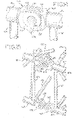
- the boom segments preferably include brackets so that hydraulic pin insertion equipment can be mounted on the boom segment in a position to force the main pin through the apertures.
- Fig. 5a shows one such configuration for a hydraulic pin inserter.
- Brackets 92 support the extensions 96 of pins 95 that are sized to fit in the apertures in the extensions 71, 72, 73, 81 and 82.
- Another bracket 91 is connected to the center of the top lacing element 65 that spans between the ends of top chords 61.
- a hydraulic pin insertion/retraction tool 93 with a double acting hydraulic cylinder can fit into one side of bracket 91 and connect to the extension 96 of the pin 95.
- pin 94 is removed, allowing bracket 91 to pivot about pin 97 into an upper position. Pin 94 is then inserted through holes 98 and the tool 93 can be put back into the bracket 91 and connected to the extension 96 of the upper pin 95. Retraction of the pins is carried out in a reverse operation.
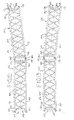
- a second embodiment of the invention is shown in 12-21. Many of the elements in the second embodiment are just like the elements in the first embodiment. Reference numbers for these items that are identical between the two embodiments are the same with an addend of 100.
- the boom segments 152 and 154 have chords 161 and 163 and lacing elements 165.
- the preferred connectors for this embodiment are also of two types, which may be referred to as first and second connectors, shown in detail in Figs. 18-21 .
- Fig. 14 shows a mated connection between two sectional boom members 153 and 154.
- a first connecter 170 is affixed to the second end of a top chord 161 on a first sectional boom member 153.
- the connector 170 has three extensions 171, 172, 173, each having an aperture there through.
- the connector 170 also includes an engagement member in the form of a guide pin 174 captured in an additional aperture though the extensions 171-173.
- the engagement member extends from the outer extensions 171 and 173, generally parallel to the axis of the apertures in the extensions of the connector 170.
- the engagement member provides both an alignment surface and a stop surface.
- the second connector 180 is affixed to the first end of a top chord 161 on a second sectional boom member 154.
- the second connector 180 has two extensions 181 and 182, each having an aperture there through.
- the extensions 171, 172 and 173 are interleaved with the extensions 181 and 182 when the connectors are mated.
- the connector 180 has a second alignment surface, in the form of a pin seat 184 matching the outer circumference of the guide pin 174, formed on the outside of the extensions 181 and 182.
- the first and second alignment surfaces allow the connectors to be brought into a close enough alignment such that a main pin (not shown) can be placed through the apertures of the interleaved extensions, securing the connectors 170 and 180 in a pivotal relationship, as shown in Fig. 14 .
- a main pin not shown
- the second alignment surface 184 and the guide pin 174 loose contact with one another for a slight distance when the boom segments are in axial alignment.
- the connectors 170 and 180 can still be coupled to one another and the main pin inserted through the apertures in the extensions 171, 172, 173, 181 and 182. Thereafter, when the boom segments are pivoted about the main pin, the second alignment surface 184 on the other connector will contact the guide pin 174 to stop the pivoting at the point where the boom segments are aligned. In this way, the same structure that provides alignment surfaces in one set of connectors provides stop surfaces in the other connectors on the boom segment.
- the bottom chords 163 are provided with connectors that have the same configuration as the connectors 170 and 180 on the top chords 161, but the connectors are installed in mirror image fashion, as shown in Fig. 15 .
- the first alignment surfaces 174 and second alignment surfaces 184 on the connectors of the top chords 161 are on opposite sides of the connectors compared to the first alignment surfaces 174 and second alignment surfaces 184 on the connectors of the bottom chords.
- the first alignment surfaces and second alignment surfaces on the connectors of the top chords face the bottom chords
- the first alignment surfaces and second alignment surfaces on the connectors of the bottom chords face the top chords.
- the connectors of the second embodiment also allow sectional boom members to be connected and then rotate through a full 90° angle. Even if the boom segments are at an angle of 90° from their aligned position, the apertures through the extensions can be lined up and a pin inserted. Of course in this position the first and second alignment surfaces and do not contact each other.
- the boom segments are assembled from a non-aligned arrangement as shown in either of Figs. 12 or 13 , the following steps will normally occur.
- the two boom segments will be brought together such that two connectors 170 on the first boom segment 153 mate with two respective connectors 180 on the second boom segment 154 to form two pairs of mated connectors, but the longitudinal axes 141 of the two segments are not aligned.
- each segment is not coupled.
- the mated connectors are fastened together with a pivoting connection as main pins are inserted though the apertures of both pairs of mated connectors.
- the two segments 153 and 154 are then pivoted with respect to each other about the pivoting connection until the first alignment surface on the non-coupled connectors of the first segment 153 contacts the second alignment surfaces on the non-coupled connectors of the second segment 154.
- the previously non-coupled connectors are then pinned to their respective mating connector.
- This arrangement allows the boom sections to "back bend" about either the top or bottom boom connection.
- the boom sections can be rotatably engaged with either the top or bottom pins inserted, and then pivoted to a position where the segments are aligned and the opposite connectors can be pinned.
- the boom segments may also be brought together in a generally aligned position, where the connectors on the top and bottom chords contact each other at roughly the same time. It will be appreciated that with the preferred geometry of the connectors, if the boom sections are not exactly aligned as they come together, the radius on the outside of extensions 181 and 182 will engage the pin 174 and force the connectors to slide around the pin 174, thus urging the boom segments into the proper alignment such that when the engagement member and second alignment surface on both the upper and lower sets of connectors are fully engaged, the apertures through the extensions in the connectors are aligned such that a main pin can be inserted through the apertures of all extensions in the first and second mating connectors.
- compressive loads on the boom generate shear forces in the main pin holding the first and second connectors together.
- the compressive loads are carried by four shear surfaces in each of the main pins, which allows the diameter of those pins to be reduced compared to a system with only a double shear connection.
- One of the benefits of either embodiment is that common castings can be used to make all four connectors on the same end of the boom segment, which simplifies manufacturing.
- the castings are pre-machined and then welded to the chord members.
- the chord members are then assembled into a boom segment, and then final machining on the connectors is performed. This procedure allows the final configuration of the connectors to be made without having to worry about distortion due to welding and machining of the large boom sections.
- the figures show all four of the connectors having the same number of extensions on a given end of a boom segment.
- connectors 70 could be used on the top chords and connectors 80 used on the bottom chords at one end of a segment, with connectors 80 being on the top chords and connectors 70 being on the bottom chords on the opposite end of the segment.
- Another advantage of the present invention is particularly useful for very high capacity booms. While the connectors are primarily designed for large compressive loads, there may be times when the connectors need to be able to handle tension loads across the connections. The pins through the apertures are able to handle these tension loads.
Applications Claiming Priority (3)
| Application Number | Priority Date | Filing Date | Title |
|---|---|---|---|
| US99097707P | 2007-11-29 | 2007-11-29 | |
| EP08253694.7A EP2065332B1 (en) | 2007-11-29 | 2008-11-11 | Connection system for crane boom segments |
| EP14184310.2A EP2818443B1 (en) | 2007-11-29 | 2008-11-11 | Connection system for crane boom segments |
Related Parent Applications (3)
| Application Number | Title | Priority Date | Filing Date |
|---|---|---|---|
| EP14184310.2A Division-Into EP2818443B1 (en) | 2007-11-29 | 2008-11-11 | Connection system for crane boom segments |
| EP14184310.2A Division EP2818443B1 (en) | 2007-11-29 | 2008-11-11 | Connection system for crane boom segments |
| EP08253694.7A Division EP2065332B1 (en) | 2007-11-29 | 2008-11-11 | Connection system for crane boom segments |
Publications (2)
| Publication Number | Publication Date |
|---|---|
| EP3028982A1 EP3028982A1 (en) | 2016-06-08 |
| EP3028982B1 true EP3028982B1 (en) | 2018-04-25 |
Family
ID=40291019
Family Applications (3)
| Application Number | Title | Priority Date | Filing Date |
|---|---|---|---|
| EP15200561.7A Active EP3028982B1 (en) | 2007-11-29 | 2008-11-11 | Connection system for crane boom segments |
| EP14184310.2A Active EP2818443B1 (en) | 2007-11-29 | 2008-11-11 | Connection system for crane boom segments |
| EP08253694.7A Active EP2065332B1 (en) | 2007-11-29 | 2008-11-11 | Connection system for crane boom segments |
Family Applications After (2)
| Application Number | Title | Priority Date | Filing Date |
|---|---|---|---|
| EP14184310.2A Active EP2818443B1 (en) | 2007-11-29 | 2008-11-11 | Connection system for crane boom segments |
| EP08253694.7A Active EP2065332B1 (en) | 2007-11-29 | 2008-11-11 | Connection system for crane boom segments |
Country Status (8)
| Country | Link |
|---|---|
| US (3) | US7954657B2 (ru) |
| EP (3) | EP3028982B1 (ru) |
| JP (2) | JP2009149438A (ru) |
| KR (1) | KR20090056830A (ru) |
| CN (2) | CN105174092B (ru) |
| BR (1) | BRPI0805009A2 (ru) |
| MX (1) | MX2008014727A (ru) |
| RU (2) | RU2525162C2 (ru) |
Families Citing this family (35)
| Publication number | Priority date | Publication date | Assignee | Title |
|---|---|---|---|---|
| JP2009149438A (ja) * | 2007-11-29 | 2009-07-09 | Manitowoc Crane Companies Ltd | クレーンブームセグメント用の接続システム |
| US8397924B2 (en) | 2008-09-19 | 2013-03-19 | Manitowoc Crane Companies, Llc | Drum frame system for cranes |
| US9441423B2 (en) * | 2008-02-29 | 2016-09-13 | National Oilwell Varco, L.P. | Drilling rig masts and methods of assembly and erection |
| DE102009022262A1 (de) * | 2009-05-22 | 2010-11-25 | Terex Demag Gmbh | Winkelverstellung eines Auslegersystems |
| DE202010004584U1 (de) * | 2010-04-06 | 2011-10-05 | Liebherr-Werk Ehingen Gmbh | Gittermastkran und Gittermastausleger |
| US8739988B2 (en) * | 2010-09-20 | 2014-06-03 | Manitowoc Crane Companies, Llc | Pinned connection system for crane column segments |
| EP2476642B1 (en) | 2011-01-12 | 2013-07-24 | Manitowoc Crane Companies, LLC | Method of connecting crane suspension assembly sections together and frame mounted assembly used therefore |
| DE102011122812A1 (de) * | 2011-05-09 | 2012-11-15 | Liebherr-Werk Ehingen Gmbh | Verfahren zur Montage eines Mobilkrans sowie Mobilkran |
| CN102500939B (zh) * | 2011-11-03 | 2014-10-15 | 常州海杰冶金机械制造有限公司 | 塔式起重机平衡臂的装配方法 |
| CN102491192B (zh) * | 2011-12-15 | 2013-10-16 | 中联重科股份有限公司 | 塔机引进平台结构 |
| US9091125B2 (en) | 2012-01-16 | 2015-07-28 | National Oilwell Varco, L.P. | Collapsible substructure for a mobile drilling rig |
| US9206021B2 (en) | 2012-09-26 | 2015-12-08 | Kobelco Cranes Co., Ltd. | Crane and crane assembling method |
| US20140131300A1 (en) * | 2012-11-09 | 2014-05-15 | Gru Comedil S.R.L. | Jib for a crane |
| EP2746214B1 (en) | 2012-12-20 | 2016-04-27 | Manitowoc Crane Companies, LLC | Column connector system |
| JP6079269B2 (ja) * | 2013-01-29 | 2017-02-15 | コベルコ建機株式会社 | 起伏部材 |
| US9815674B2 (en) | 2013-02-21 | 2017-11-14 | Manitowoc Crane Companies, Llc | Pin puller for crane connections |
| CN103434950B (zh) * | 2013-09-06 | 2015-06-17 | 徐州重型机械有限公司 | 桁架臂加长节、具有该加长节的桁架臂及起重机 |
| CN104512821A (zh) * | 2014-12-23 | 2015-04-15 | 中联重科股份有限公司 | 工程机械的起重臂和工程机械 |
| JP6531448B2 (ja) * | 2015-03-20 | 2019-06-19 | 株式会社タダノ | ジブ連結構造 |
| JP6160660B2 (ja) * | 2015-07-16 | 2017-07-12 | コベルコ建機株式会社 | アタッチメントの連結装置 |
| US10647552B1 (en) * | 2015-09-25 | 2020-05-12 | Link-Belt Cranes, L.P., Lllp | Fly connection system for a crane boom |
| WO2017070396A1 (en) * | 2015-10-21 | 2017-04-27 | Lindsey Manufacturing Co. | Apparatus and method for helicopter erection of emergency restoration structure |
| CN105439008B (zh) * | 2015-12-29 | 2017-07-18 | 中联重科股份有限公司 | 桁架铰耳连接结构、桁架延长臂架、臂架系统和起重机 |
| GB2546075A (en) * | 2016-01-05 | 2017-07-12 | Oclu Ltd | A camera mount |
| JP6447581B2 (ja) * | 2016-06-17 | 2019-01-09 | コベルコ建機株式会社 | 連結ピン引抜用治具、およびクレーン |
| JP6874332B2 (ja) * | 2016-11-07 | 2021-05-19 | コベルコ建機株式会社 | 起伏体および当該起伏体を備えた作業機械の組立方法 |
| CN106395645B (zh) * | 2016-12-02 | 2018-10-02 | 徐州重型机械有限公司 | 风电臂翻转方法及起重机 |
| JP7021474B2 (ja) | 2017-08-18 | 2022-02-17 | コベルコ建機株式会社 | ラチス構造物の製造方法 |
| NL2019511B1 (en) * | 2017-09-08 | 2019-03-19 | Mammoet Eng B V | Crane comprising first mast with tiltable first mast upper part |
| JP6638718B2 (ja) * | 2017-12-18 | 2020-01-29 | コベルコ建機株式会社 | クレーン立組方法 |
| US20190186135A1 (en) * | 2017-12-18 | 2019-06-20 | Tiffin Scenic Studios, Inc. | Connector system for trusses |
| JP6870692B2 (ja) * | 2018-05-18 | 2021-05-12 | コベルコ建機株式会社 | ラチス構造物、ラチス構造物連結体、作業機械、及びコネクタ |
| IT201900005782A1 (it) * | 2019-04-15 | 2020-10-15 | Fin Group S R L | Dispositivo di sollevamento trasportabile |
| DE102020110406A1 (de) * | 2020-04-16 | 2021-10-21 | Liebherr-Werk Ehingen Gmbh | Mobile Bolzenzieheinrichtung |
| DE102020131617B4 (de) * | 2020-11-30 | 2022-06-23 | Liebherr-Werk Ehingen Gmbh | Mobilkran umfassend einen Oberwagen mit wenigstens einer Lagerstelle zum Anbolzen eines Auslegers |
Citations (2)
| Publication number | Priority date | Publication date | Assignee | Title |
|---|---|---|---|---|
| EP2065332A2 (en) * | 2007-11-29 | 2009-06-03 | Manitowoc Crane Companies, Inc. | Connection system for crane boom segments |
| US20100213155A1 (en) * | 2009-02-26 | 2010-08-26 | Hitachi Sumitomo Heavy Industries Construction Crane Co., Ltd. | Rotating Superstructure and Crane |
Family Cites Families (47)
| Publication number | Priority date | Publication date | Assignee | Title |
|---|---|---|---|---|
| US2529454A (en) * | 1948-01-10 | 1950-11-07 | Eugene P Reading Inc | Foldable boom |
| US2975910A (en) * | 1958-06-06 | 1961-03-21 | Clark Equipment Co | Crane boom |
| US3085695A (en) * | 1961-03-23 | 1963-04-16 | Carl A Miller | Hinge for crane boom |
| GB1179394A (en) * | 1966-03-17 | 1970-01-28 | Winget Ltd | Mobile Load Lifting Apparatus |
| US3977530A (en) | 1974-06-13 | 1976-08-31 | The Manitowoc Company, Inc. | Crane with gantry backhitch and boom hoist assembly removable as a unit |
| US3955684A (en) | 1975-02-06 | 1976-05-11 | Harnischfeger Corporation | Rotary crane structure with a selective drive on power unit |
| CA1033688A (en) | 1975-10-23 | 1978-06-27 | Manitowoc Company | Demountable gantry, boom hoist and counter-weight |
| US4273244A (en) | 1979-01-29 | 1981-06-16 | Fmc Corporation | Crane upperstructure self-transferring system |
| JPS5749890U (ru) * | 1980-09-09 | 1982-03-20 | ||
| JPS5791781U (ru) * | 1980-11-27 | 1982-06-05 | ||
| IT8220442V0 (it) * | 1982-01-12 | 1982-01-12 | Ind Metalmeccaniche Per Azioni | Gruppo di giunzione fra elementi di strutture metalliche, di gru in particolare. |
| US4582205A (en) | 1983-06-29 | 1986-04-15 | Fmc Corporation | Modularized pedestal-mount crane and method of disassembly |
| JPS60252590A (ja) * | 1984-05-29 | 1985-12-13 | 日立建機株式会社 | クレ−ン本体とブ−ムとの連結構造 |
| DE3706301C1 (en) | 1987-02-24 | 1987-10-15 | Mannesmann Ag | Connecting sections of a lattice pole in the jib system of a movable crane |
| DE3842726C3 (de) * | 1988-12-19 | 2001-01-18 | Mannesmann Ag | Mehrschnittige Bolzenverbindung |
| JP2550068Y2 (ja) * | 1990-12-11 | 1997-10-08 | 大成建設株式会社 | 水平ジブクレーン |
| US5199586A (en) * | 1991-07-25 | 1993-04-06 | The Manitowoc Company, Inc. | Quick-connect sectional boom members for cranes and the like |
| US5484069A (en) | 1991-09-20 | 1996-01-16 | The Manitowoc Company, Inc. | Process for self-disassembling a crawler crane |
| US5443169A (en) | 1992-09-15 | 1995-08-22 | The Manitowoc Company | Crane backhitch |
| JP3258472B2 (ja) * | 1993-11-08 | 2002-02-18 | 株式会社小松製作所 | 水平ブームの張り出し、格納装置 |
| JPH07144885A (ja) * | 1993-11-26 | 1995-06-06 | Hitachi Constr Mach Co Ltd | クレーンブーム組立体 |
| DE4402005A1 (de) * | 1994-01-18 | 1995-07-20 | Mannesmann Ag | Ein- oder mehrschnittige Bolzenverbindung für Kran-Auslegerteile |
| JP3100115B2 (ja) * | 1995-12-04 | 2000-10-16 | 株式会社小松製作所 | クレーンのジブ張り出し、格納装置 |
| JP3980123B2 (ja) | 1996-04-26 | 2007-09-26 | マニタウォック クレイン カンパニーズ インコーポレイテッド | ブームホイストシリンダクレーン |
| US6131751A (en) | 1996-04-26 | 2000-10-17 | Manitowoc Crane Group, Inc. | Counter weight handling system and boom parking device |
| GB2316383B (en) | 1996-08-23 | 2000-04-05 | Liebherr Werk Ehingen | Mobile crane |
| US6481202B1 (en) | 1997-04-16 | 2002-11-19 | Manitowoc Crane Companies, Inc. | Hydraulic system for boom hoist cylinder crane |
| CA2266791C (en) | 1998-03-27 | 2005-02-01 | Manitowoc Crane Group, Inc. | Four track crawler crane |
| US6213318B1 (en) * | 1999-03-01 | 2001-04-10 | Manitowoc Crane Group, Inc. | Rotatable connection system for crane boom sections |
| US6702132B1 (en) | 1999-03-19 | 2004-03-09 | Link-Belt Construction Equipment Company, L.P., Lllp | Crane self-assembly system |
| DE10056647A1 (de) * | 2000-11-09 | 2002-05-23 | Atecs Mannesmann Ag | Verfahren zum Transport von Gittermastkranen |
| US7007764B2 (en) | 2002-12-06 | 2006-03-07 | Manitowoc Crane Companies, Inc. | Carbody to crawler connection |
| ATE468299T1 (de) * | 2003-04-02 | 2010-06-15 | Terex Demag Gmbh | Zweiteiliger hauptausleger für einen gittermastkran und verfahren zum aufrichten davon |
| FR2853891B1 (fr) * | 2003-04-17 | 2006-05-19 | Potain Sa | Dispositif d'assemblage demontable des elements de fleche d'une grue a tour |
| ITBO20030764A1 (it) | 2003-12-19 | 2005-06-20 | Ferrari Spa | Telaio metallico composto dall'unione di una pluralita' di elementi estrusi e metodo per la sua realizzazione |
| JP4247222B2 (ja) | 2005-09-20 | 2009-04-02 | ヤンマー株式会社 | トラクターローダーバックホーの掘削装置固定構造 |
| JP2007302352A (ja) | 2006-05-08 | 2007-11-22 | Kobelco Cranes Co Ltd | クレーン及びクレーンのブーム起伏装置 |
| US7546928B2 (en) | 2006-10-27 | 2009-06-16 | Manitowoc Crane Companies, Inc. | Mobile lift crane with variable position counterweight |
| US7967158B2 (en) | 2006-10-27 | 2011-06-28 | Manitowoc Crane Companies, Llc | Mobile lift crane with variable position counterweight |
| DE102006060347B4 (de) | 2006-12-20 | 2008-09-25 | Liebherr-Werk Ehingen Gmbh | Gitterstück für einen mobilen Großkran und Verfahren zu seinem Aufrichten |
| US7762412B2 (en) | 2007-04-26 | 2010-07-27 | Manitowoc Crane Companies, Llc | Mast raising structure and process for high-capacity mobile lift crane |
| DE202008001272U1 (de) | 2008-01-29 | 2009-06-04 | Daas, Kamal | Gittertragwerk |
| NL1035078C1 (nl) * | 2008-02-26 | 2008-03-18 | Ale Heavylift R & D B V | Mastdeel. |
| US8622228B2 (en) | 2008-09-19 | 2014-01-07 | Manitowoc Crane Companies, Llc | Boom hoist transportation system and crane using same |
| CN102249161A (zh) | 2010-05-21 | 2011-11-23 | 上海三一科技有限公司 | 一种起重机多主弦杆臂架 |
| US8739988B2 (en) * | 2010-09-20 | 2014-06-03 | Manitowoc Crane Companies, Llc | Pinned connection system for crane column segments |
| EP2476642B1 (en) | 2011-01-12 | 2013-07-24 | Manitowoc Crane Companies, LLC | Method of connecting crane suspension assembly sections together and frame mounted assembly used therefore |
-
2008
- 2008-11-05 JP JP2008284263A patent/JP2009149438A/ja active Pending
- 2008-11-11 EP EP15200561.7A patent/EP3028982B1/en active Active
- 2008-11-11 EP EP14184310.2A patent/EP2818443B1/en active Active
- 2008-11-11 EP EP08253694.7A patent/EP2065332B1/en active Active
- 2008-11-18 KR KR1020080114465A patent/KR20090056830A/ko not_active Application Discontinuation
- 2008-11-18 US US12/273,310 patent/US7954657B2/en active Active
- 2008-11-19 MX MX2008014727A patent/MX2008014727A/es not_active Application Discontinuation
- 2008-11-27 RU RU2008146869/11A patent/RU2525162C2/ru not_active IP Right Cessation
- 2008-11-28 BR BRPI0805009-0A patent/BRPI0805009A2/pt not_active IP Right Cessation
- 2008-12-01 CN CN201510356025.XA patent/CN105174092B/zh active Active
- 2008-12-01 CN CN200810178816.8A patent/CN101456520B/zh active Active
-
2011
- 2011-06-06 US US13/154,236 patent/US8534474B2/en active Active
-
2013
- 2013-06-07 US US13/912,884 patent/US9187296B2/en active Active
-
2014
- 2014-06-06 RU RU2014123123/11A patent/RU2014123123A/ru not_active Application Discontinuation
-
2015
- 2015-10-19 JP JP2015205650A patent/JP6286407B2/ja active Active
Patent Citations (2)
| Publication number | Priority date | Publication date | Assignee | Title |
|---|---|---|---|---|
| EP2065332A2 (en) * | 2007-11-29 | 2009-06-03 | Manitowoc Crane Companies, Inc. | Connection system for crane boom segments |
| US20100213155A1 (en) * | 2009-02-26 | 2010-08-26 | Hitachi Sumitomo Heavy Industries Construction Crane Co., Ltd. | Rotating Superstructure and Crane |
Also Published As
| Publication number | Publication date |
|---|---|
| KR20090056830A (ko) | 2009-06-03 |
| EP2065332A2 (en) | 2009-06-03 |
| US9187296B2 (en) | 2015-11-17 |
| EP2065332A3 (en) | 2011-11-02 |
| RU2008146869A (ru) | 2010-06-10 |
| CN105174092B (zh) | 2018-03-13 |
| BRPI0805009A2 (pt) | 2010-07-27 |
| EP2818443B1 (en) | 2016-03-23 |
| JP2009149438A (ja) | 2009-07-09 |
| US8534474B2 (en) | 2013-09-17 |
| EP3028982A1 (en) | 2016-06-08 |
| US20110233165A1 (en) | 2011-09-29 |
| CN101456520B (zh) | 2015-07-29 |
| RU2525162C2 (ru) | 2014-08-10 |
| US20130270208A1 (en) | 2013-10-17 |
| EP2065332B1 (en) | 2014-09-24 |
| US20090139948A1 (en) | 2009-06-04 |
| JP2016040204A (ja) | 2016-03-24 |
| US7954657B2 (en) | 2011-06-07 |
| EP2818443A1 (en) | 2014-12-31 |
| CN105174092A (zh) | 2015-12-23 |
| CN101456520A (zh) | 2009-06-17 |
| MX2008014727A (es) | 2009-05-28 |
| JP6286407B2 (ja) | 2018-02-28 |
| RU2014123123A (ru) | 2015-12-20 |
Similar Documents
| Publication | Publication Date | Title |
|---|---|---|
| EP3028982B1 (en) | Connection system for crane boom segments | |
| EP2431322B1 (en) | Crane with pinned connection system for crane column segments | |
| EP1044922B1 (en) | Rotatable connection system for crane boom sections | |
| JP5513820B2 (ja) | トラニオン運搬システム及びそれを使用するクレーン | |
| US10717633B2 (en) | Adjustable length tensioning member | |
| JP3415908B2 (ja) | リングセグメント連結部 | |
| JP2004189219A (ja) | 車体とクローラの連結部 | |
| RU2574670C2 (ru) | Кран и сопряженное соединение между секционными элементами крана |
Legal Events
| Date | Code | Title | Description |
|---|---|---|---|
| PUAI | Public reference made under article 153(3) epc to a published international application that has entered the european phase |
Free format text: ORIGINAL CODE: 0009012 |
|
| 17P | Request for examination filed |
Effective date: 20151216 |
|
| AC | Divisional application: reference to earlier application |
Ref document number: 2818443 Country of ref document: EP Kind code of ref document: P Ref document number: 2065332 Country of ref document: EP Kind code of ref document: P |
|
| AK | Designated contracting states |
Kind code of ref document: A1 Designated state(s): AT DE |
|
| GRAP | Despatch of communication of intention to grant a patent |
Free format text: ORIGINAL CODE: EPIDOSNIGR1 |
|
| INTG | Intention to grant announced |
Effective date: 20170516 |
|
| GRAJ | Information related to disapproval of communication of intention to grant by the applicant or resumption of examination proceedings by the epo deleted |
Free format text: ORIGINAL CODE: EPIDOSDIGR1 |
|
| INTC | Intention to grant announced (deleted) | ||
| GRAP | Despatch of communication of intention to grant a patent |
Free format text: ORIGINAL CODE: EPIDOSNIGR1 |
|
| INTG | Intention to grant announced |
Effective date: 20171108 |
|
| GRAA | (expected) grant |
Free format text: ORIGINAL CODE: 0009210 |
|
| GRAS | Grant fee paid |
Free format text: ORIGINAL CODE: EPIDOSNIGR3 |
|
| AC | Divisional application: reference to earlier application |
Ref document number: 2818443 Country of ref document: EP Kind code of ref document: P Ref document number: 2065332 Country of ref document: EP Kind code of ref document: P |
|
| AK | Designated contracting states |
Kind code of ref document: B1 Designated state(s): AT DE |
|
| REG | Reference to a national code |
Ref country code: AT Ref legal event code: REF Ref document number: 992656 Country of ref document: AT Kind code of ref document: T Effective date: 20180515 |
|
| REG | Reference to a national code |
Ref country code: DE Ref legal event code: R096 Ref document number: 602008055059 Country of ref document: DE |
|
| REG | Reference to a national code |
Ref country code: DE Ref legal event code: R097 Ref document number: 602008055059 Country of ref document: DE |
|
| PLBE | No opposition filed within time limit |
Free format text: ORIGINAL CODE: 0009261 |
|
| STAA | Information on the status of an ep patent application or granted ep patent |
Free format text: STATUS: NO OPPOSITION FILED WITHIN TIME LIMIT |
|
| 26N | No opposition filed |
Effective date: 20190128 |
|
| REG | Reference to a national code |
Ref country code: AT Ref legal event code: UEP Ref document number: 992656 Country of ref document: AT Kind code of ref document: T Effective date: 20180425 |
|
| PGFP | Annual fee paid to national office [announced via postgrant information from national office to epo] |
Ref country code: DE Payment date: 20231121 Year of fee payment: 16 Ref country code: AT Payment date: 20231121 Year of fee payment: 16 |