EP3024019B1 - Verfahren zum direkten Verbinden von Halbleitersubstraten - Google Patents
Verfahren zum direkten Verbinden von Halbleitersubstraten Download PDFInfo
- Publication number
- EP3024019B1 EP3024019B1 EP14194506.3A EP14194506A EP3024019B1 EP 3024019 B1 EP3024019 B1 EP 3024019B1 EP 14194506 A EP14194506 A EP 14194506A EP 3024019 B1 EP3024019 B1 EP 3024019B1
- Authority
- EP
- European Patent Office
- Prior art keywords
- layer
- sicn
- dielectric
- substrates
- bonding
- Prior art date
- Legal status (The legal status is an assumption and is not a legal conclusion. Google has not performed a legal analysis and makes no representation as to the accuracy of the status listed.)
- Active
Links
Images


Classifications
-
- H10W74/147—
-
- H10P90/1914—
-
- H10W90/00—
-
- H10P14/6336—
-
- H10P14/6682—
-
- H10P14/6905—
-
- H10P14/69215—
-
- H10P70/237—
-
- H10P95/062—
-
- H10W72/01351—
-
- H10W72/01353—
-
- H10W72/01365—
-
- H10W72/019—
-
- H10W72/01935—
-
- H10W72/01938—
-
- H10W72/01951—
-
- H10W72/01953—
-
- H10W72/073—
-
- H10W72/07311—
-
- H10W72/07355—
-
- H10W72/351—
-
- H10W72/90—
-
- H10W72/923—
-
- H10W72/941—
-
- H10W72/9415—
-
- H10W72/953—
-
- H10W80/041—
-
- H10W80/102—
-
- H10W80/312—
-
- H10W80/327—
-
- H10W80/333—
-
- H10W80/701—
-
- H10W90/792—
Definitions
- the present invention is related to direct bonding processes wherein a semiconductor substrate is bonded to another semiconductor substrate by forming chemical bonds between the contact surfaces.
- Direct bonding on wafer level involves the alignment and contacting at room temperature of two semiconductor wafers, usually silicon wafers, followed by an annealing step, during which step chemical bonds are formed between the materials on at least a portion of the contacted wafer surfaces.
- CMP Chemical Mechanical Polishing
- Surface treatments are applied such as plasma treatment and ultrasonic or other cleaning techniques.
- Required post-bond annealing temperatures are generally higher than 400°C in order to reach the desired bond strength. In order to reduce the thermal budget of the bonding process, it is desirable to obtain high strength bonds at lower temperatures. This is particularly important in the field of memory devices.
- an additional problem is the diffusion of the metal into the dielectric bonding layer. This is the case for example when silicon oxide bonding is applied to bonding of hybrid wafers that comprise copper line patterns, resulting in direct Cu contact to the oxide surface of the mating wafer. During annealing, the Cu may diffuse in the oxide, resulting in leakage or shorting between interconnect nets. In order to avoid this diffusion, a dielectric bonding layer can be applied that forms a barrier against the Cu-diffusion, such as silicon nitride. However, this makes achieving a high bonding force more difficult and increases the interconnect capacitance due to the higher dielectric constant of the Si nitride versus the Si oxide.
- SiCN as bonding layer is furthermore known from US2013/009321 and US2012/211849 .
- a CMP step reducing the roughness of the bonding layer is known from US2013/270328 .
- a CMP step reducing the roughness of the bonding layer to less than or equal to 0.1nm RMS is described in US2012/043647 and US2008/061419 .
- the invention is related to a method as disclosed in the appended claims.
- the present invention is related to a method for bonding a first semiconductor substrate to a second semiconductor substrate by direct bonding, wherein the substrates are both provided on their contact surfaces with a dielectric layer, followed by a CMP step for reducing the roughness of the dielectric layer.
- the dielectric layer after CMP has an roughness of less than 0.2nm RMS.
- a layer of SiCN with a thickness between 10nm and 150nm is deposited onto the thinned dielectric layer, followed by a CMP step which reduces the roughness of the SiCN layer to the order of 1 tenth of a nanometre.
- the RMS value after CMP is less than 0.1nm RMS.
- the substrates are subjected to a pre-bond annealing step.
- the substrates are then bonded by direct bonding, possibly preceded by one or more pre-treatments of the contact surfaces, and followed by a post-bond annealing step, at a temperature of less than or equal to 250°C, preferably between 200°C and 250°C. It has been found that the bond strength is excellent, even at the above named annealing temperatures, which are lower than presently known in the art.
- the invention is thus related to a method for bonding a first semiconductor substrate to a second semiconductor substrate as defined in the appended claims, wherein both substrates are subjected to the following steps, prior to bonding :
- the annealing temperature of the post-bond annealing step is less than or equal to 250°C, more preferably said temperature is between 200°C and 250°C.
- the substrates are blanket wafers, wherein the dielectric and SiCN layers are continuous layers.
- the substrates are hybrid dielectric/metal wafers comprising a patterned surface having areas of dielectric material and areas of metal, and the pre-bond annealing step is followed by :
- the temperature during bonding is the same as the post-bond annealing temperature.
- the pre-bond annealing temperature may be between 400°C and 450°C.
- silicon oxide and silicon carbon nitride are defined as follows.
- Silicon oxide is defined by the formula SiO x , with x between 1.4 and 2.1.
- Silicon carbon nitride, hereafter referred to as SiCN is defined by the formula SiC y N z with y between 0.7 and 1.1 and z between 0.1 and 0.4.
- the term SiCN also includes layers of SiC y N z :H, wherein the 'H' represents hydrogen atoms attached to the SiCN molecules. This may be obtained as a consequence of the precursors used in the deposition method for the SiCN layers.
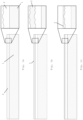
- Figure 1 illustrates the process steps of a wafer-to-wafer bonding process according to the invention, for the direct bonding of two blanket wafers, i.e. wafers covered over their entire surface with a dielectric bonding layer.
- the wafers may be silicon wafers comprising a silicon bulk portion 1 and a functional layer 2 which may comprise semiconductor devices together with a stack of interconnect layers, said functional layer being best known in the art as a FEOL/BEOL layer (Front-end-of-line/Back-end-of-line).
- the aim is to produce a bond between two such wafers.
- a microscopic but significant roughness is exhibited by the FEOL/BEOL layer 2, which may be mainly due to a degree of surface topography of the layer.
- a thick layer 3 of SiO x is then deposited onto the FEOL/BEOL layer 2, see Figure 1b , covering the totality of said FEOL/BEOL layer 2.
- the SiO x layer thickness is high compared to the roughness of the FEOL/BEOL layer, e.g. at least ten times higher that said roughness (expressed as RMS value or expressed as a step height value when the roughness of the FEOL/BEOL layer 2 is mainly defined by the topography).
- the SiO x layer 3 may have a thickness between 100 nm and 6 micron.
- the SiO x layer is then thinned by a CMP step, thereby reducing the roughness to a lower value less than or equal to 0.2 nm RMS ( Figure 1c ).
- a SiO x layer other dielectric layers may be used, e.g. a silicon nitride layer.
- the dielectric layer 3 is an inorganic dielectric layer. An organic dielectric layer 3 is not excluded, but in that case, a curing step of the dielectric layer is required to avoid outgassing of the layer during subsequent process steps.
- a layer 4 of SiCN is deposited onto the thinned SiO x layer ( Figure 1d ).
- the deposition may take place by Plasma Enhanced Chemical Vapour Deposition (PECVD), resulting in an amorphous SiCN layer 4.
- the thickness of the SiCN layer at this stage is between 10nm and 150nm, preferably between 50 nm and 150 nm.
- the wafers are then subjected to an pre-bond annealing step.
- a CMP step is then performed on the SiCN layer, reducing the roughness of the layer to the order of tenths of a nanometre, such that its is equal to or less than 0.1nm RMS ( Figure 1e ).
- the steps illustrated in Figures 1a to 1d may be performed as part of a BEOL integration scheme.
- the pre-bond anneal temperature is preferably compatible with such an integration scheme, and may be between 400°C and 450°C, preferably around 420°C.
- the wafers which have both been prepared in the above-described way are then aligned and bonded ( Figure 1f ) to form an assembly of the two bonded substrates.
- Any standard alignment technique known in the art can be used, for example based on a camera image of the wafers to be aligned or based on interferometry.
- a number of pre-treatments are performed on the contact surfaces, such as a plasma treatment and/or a cleaning step (e.g. megasonic cleaning).
- the bonding takes place in a bonding tool as known per se in the art, wherein possibly some of the pre-treatments may be performed as well.
- the bond is produced by bringing the two polished SiCN surfaces in contact with each other under appropriate process conditions (see further).
- the extremely low surface roughness facilitates the formation of chemical bonds between the contact surfaces, thereby improving the bond strength between the wafers.
- the bond strength is further improved by a post-bond annealing step performed while the wafers are in contact, at a temperature of less than or equal to 250°C, preferably between 200°C and 250°C. Despite the low anneal temperature, the bond strength between the wafers is excellent.
- FIG. 2 illustrates the method of the invention in the case of the direct bonding of hybrid dielectric/metal wafers.
- Each of the wafers that are to be bonded comprises metal islands 10 on the surface of the FEOL/BEOL layer 2. These islands can represent contact pads or metal lines.
- the surface of the FEOL/BEOL layer 2 again shows a degree of roughness, as illustrated in the detail of Figure 2a .
- openings 11 in the stack of SiO x/ SiCN layers ( Figure 2e ), said openings being formed above a number of the metal islands 10 of the FEOL/BEOL layer 2.
- the formation of these openings can take place by standard lithography steps known in the art and not described in detail here.
- the openings are formed by removing the SiO x and SiCN throughout the complete thickness of the SiO x /SiCN stack, thereby exposing the metal 10 at the bottom of the openings.
- a layer 12 of Cu is deposited in the openings and on top of the wafer. This may be done by any suitable technique known in the art.
- a barrier layer and a Cu seed layer is deposited (not shown), followed by the electrodeposition of Cu 12 inside the openings and on top of the wafer ( Figure 2f ).
- a CMP step is then performed which removes the Cu from the upper surface of the wafer.
- the SiCN layer 4 acts as a stopping layer for the CMP, as it exhibits a higher resistance to CMP than copper.
- the CMP step reduces the roughness of the SiCN layer to the order of tenths of a nanometre, equal to or less than 0.1nm RMS. This results in the wafer as shown in Figure 2g , where Cu regions 13 are surrounded by smooth SiCN areas 14.
- the steps illustrated in Figures 2a to 2g may be performed as part of a BEOL integration scheme.
- the pre-bond anneal temperature is preferably compatible with such an integration scheme, and may be between 400°C and 450°C, preferably around 420°C.
- the bonding process is illustrated in Figure 2h . Possibly after performing pre-treatments of the type described in relation to Figure 1 , corresponding metal areas are aligned and the bond is established by bringing the wafers in contact with each other under appropriate process conditions (see further). Bond formation between Cu areas preferably requires exerting a mechanical pressure that pushes the wafers together.
- the bonding is followed by a post-bond anneal, at a temperature less than or equal to 250°C, preferably between 200°C and 250°C, resulting again in excellent bond strength between bonded SiCN areas, despite the lower temperatures.
- a post-bond anneal at a temperature less than or equal to 250°C, preferably between 200°C and 250°C, resulting again in excellent bond strength between bonded SiCN areas, despite the lower temperatures.
- the invention includes the method as described above, wherein one of the substrates is a semiconductor die instead of a wafer.
- the process parameters during the bonding process may be chosen according to known bonding technology, in terms of temperature and ambient pressure in the bonding tool, as well as the pressure exerted mechanically to push the substrates against each other. Bonding may take place at room temperature or any other suitable temperature, preferably not higher than 500°C. According to a preferred embodiment, the temperature during bonding is the same or in the same range as the post-bond anneal, so that the post-bond anneal can take place in the same tool without losing time. A preferred range for the temperature during bonding is therefore the same range of 200-250°C identified above for the post-bond anneal.
- the bonding preferably takes place at a low ambient pressure, preferably not lower than 10E-7mBar, more preferably around 10E-6mBar.
- the mechanical force used to push the substrates together may be up to 90kN, with a preferred range between 40-60kN. However in the case of the bonding between blanket wafers (as illustrated in Figure 1 , no metal areas on the surface), the bond may be established without a mechanical force being exerted.
- Two wafers having FEOL/BEOL layers 2 are to be bonded by the method of the invention. They have a surface topology defined by a step height between 20nm and 30nm.
- the deposition of the SiO x layer 3 can take place by PECVD, at 340°C, under a pressure of 1 Torr, using as precursors silane and oxygen-containing gases such as NO, NO 2 or O 2 .
- the CMP on the SiO x layers includes a timed dielectric CMP step and a regular post CMP clean (megasonic cleaning), followed by treatment in 2 brush modules and a vapour dryer, e.g. in an integrated Desica cleaner.
- the SiCN deposition takes place by PECVD, at 340°C and 1 Torr.
- the precursor gases include a mixture of at least two types of gases :
- the pre-bond anneal takes place at 420°C during 20 min, in a dissociated ammonia atmosphere containing 10%H 2 .
- the CMP on the SiCN layer includes a timed dielectric CMP step and a regular post CMP clean (megasonic cleaning), followed by treatment in 2 brush modules and a vapour dryer, e.g. in an integrated Desica cleaner, followed by a BTA (benzotriazole) rinse step.
- the post bonding annealing step is performed at 250°C during 120 min in a dissociated ammonia atmosphere comprising 10% H 2 .
- Figure 3 illustrates the bond strength (expressed as the bonding energy in J/cm 2 ) obtained between SiCN layers produced with the above-described method, and compared to the bond strength obtained with other bonding layers, subjected to the same bonding process, including a post-bond annealing step at 250°C during 2hours.
- the layers to which the invention is compared were plasma enhanced silicon oxide (PE ox) and SiN. It is clear that the bond strength between SiCN layers obtained by the method of the invention is superior to the other materials.
- Figure 4 shows bond strengths obtained between PE-ox layers as a function of the post-bond anneal temperature (each time annealing took place during 2hours). Even at a temperature of 450°C, the bond strength is lower than the bond strength obtained between SiCN layers annealed at 250°C, according to the method of the invention.
- the description of a layer being present, deposited or produced 'on' another layer or substrate includes the options of
Landscapes
- Engineering & Computer Science (AREA)
- Microelectronics & Electronic Packaging (AREA)
- Power Engineering (AREA)
- Computer Hardware Design (AREA)
- Internal Circuitry In Semiconductor Integrated Circuit Devices (AREA)
- Physics & Mathematics (AREA)
- Condensed Matter Physics & Semiconductors (AREA)
- General Physics & Mathematics (AREA)
- Manufacturing & Machinery (AREA)
Claims (8)
- Verfahren zum Bonden eines ersten Halbleitersubstrats mit einem zweiten Halbleitersubstrat, wobei beide Substrate vor dem Bonden den folgenden Schritten unterzogen werden:- Abscheidung einer dielektrischen Schicht (3) auf der Oberfläche des Substrats,- Unterziehen der dielektrischen Schicht (3) einem CMP-Schritt, um die Rauheit der dielektrischen Schicht zu verringern,- Abscheidung einer Silizium-Kohlenstoffnitrid-Schicht (4) auf der Oberfläche der dielektrischen Schicht,- Unterziehen des Substrats einem Glühschritt vor dem Bonden,- Unterziehen der SiCN-Schicht (4) einem CMP-Schritt, um die Rauheit der SiCN-Schicht zu verringern, wobei das Bonden Folgendes umfasst:- Ausrichten der Substrate,- Bringen der SiCN-Schichten (4) beider Substrate in physischen Kontakt, um eine Anordnung aus gebondeten Substraten zu bilden,und wobei das Verfahren weiter den Schritt umfasst, die Anordnung einem Glühschritt nach dem Bonden zu unterziehen, und wobei die Dicke der SiCN-Schicht vor dem Unterziehen der SiCN-Schicht einem CMP-Schritt zwischen 10 nm und 150 nm liegt,dadurch gekennzeichnet, dass- die Rauheit der dielektrischen Schicht (3) auf beiden Substraten nach dem Schritt, bei dem die dielektrischen Schichten einer CMP unterzogen werden, kleiner oder gleich 0,2 nm ist, und- die Rauheit der SiCN-Schicht (4) auf beiden Substraten nach dem Schritt, bei dem die SiCN-Schichten einer CMP unterzogen werden, kleiner oder gleich 0,1 nm RMS ist.
- Verfahren nach Anspruch 1, wobei die Glühtemperatur des Glühschritts nach dem Bonden kleiner oder gleich 250 °C ist.
- Verfahren nach Anspruch 2, wobei die Temperatur zwischen 200 °C und 250 °C liegt.
- Verfahren nach einem der vorstehenden Ansprüche, wobei die auf den Substraten abgeschiedene dielektrische Schicht (3) eine Schicht aus Siliziumoxid ist.
- Verfahren nach einem der vorstehenden Ansprüche, wobei die Substrate Blankwafer sind und wobei die dielektrischen und SiCN-Schichten (3,4) durchgehende Schichten sind.
- Verfahren nach einem der Ansprüche 1 bis 4, wobei die Substrate hybride Dielektrikum/Metall-Wafer sind, die eine strukturierte Oberfläche umfassen, die Bereiche aus dielektrischem Material und Bereiche (10) aus Metall aufweisen, und wobei auf den Glühschritt vor dem Bonden Folgendes folgt:- Ätzen von Öffnungen (11) in den Stapel aus Schichten, der durch die dielektrische Schicht (3) und die SiCN-Schicht (4) gebildet wird, wodurch Teile der Metallbereiche (10) auf dem Substrat freigelegt werden,- Abscheiden von Metall (12) in den Öffnungen (11) und auf der Oberfläche des Dielektrikum/SiCN-Stapels,- und wobei der auf der SiCN-Schicht (4) durchgeführte CMP-Schritt eine CMP ist, die auf der auf der Oberfläche des Dielektrikum/SiCN-Stapels abgeschiedenen Metallschicht (12) beginnt, das Metall von der Oberfläche entfernt und auf der SiCN-Schicht (4) endet, wodurch die Rauheit der SiCN-Schicht verringert wird.
- Verfahren nach einem der vorstehenden Ansprüche, wobei die Temperatur während des Bondens gleich der Glühtemperatur nach dem Bonden ist.
- Verfahren nach einem der vorstehenden Ansprüche, wobei die Glühtemperatur vor dem Bonden zwischen 400 °C und 450 °C liegt.
Priority Applications (3)
| Application Number | Priority Date | Filing Date | Title |
|---|---|---|---|
| EP14194506.3A EP3024019B1 (de) | 2014-11-24 | 2014-11-24 | Verfahren zum direkten Verbinden von Halbleitersubstraten |
| PCT/EP2015/077424 WO2016083332A1 (en) | 2014-11-24 | 2015-11-24 | Method for direct bonding of semiconductor substrates |
| US15/604,454 US10141284B2 (en) | 2014-11-24 | 2017-05-24 | Method of bonding semiconductor substrates |
Applications Claiming Priority (1)
| Application Number | Priority Date | Filing Date | Title |
|---|---|---|---|
| EP14194506.3A EP3024019B1 (de) | 2014-11-24 | 2014-11-24 | Verfahren zum direkten Verbinden von Halbleitersubstraten |
Publications (2)
| Publication Number | Publication Date |
|---|---|
| EP3024019A1 EP3024019A1 (de) | 2016-05-25 |
| EP3024019B1 true EP3024019B1 (de) | 2025-02-26 |
Family
ID=51982439
Family Applications (1)
| Application Number | Title | Priority Date | Filing Date |
|---|---|---|---|
| EP14194506.3A Active EP3024019B1 (de) | 2014-11-24 | 2014-11-24 | Verfahren zum direkten Verbinden von Halbleitersubstraten |
Country Status (3)
| Country | Link |
|---|---|
| US (1) | US10141284B2 (de) |
| EP (1) | EP3024019B1 (de) |
| WO (1) | WO2016083332A1 (de) |
Families Citing this family (13)
| Publication number | Priority date | Publication date | Assignee | Title |
|---|---|---|---|---|
| EP3024019B1 (de) | 2014-11-24 | 2025-02-26 | IMEC vzw | Verfahren zum direkten Verbinden von Halbleitersubstraten |
| EP3367425A1 (de) | 2017-02-28 | 2018-08-29 | IMEC vzw | Verfahren zum direkten verbinden von halbleitersubstraten |
| US10658313B2 (en) | 2017-12-11 | 2020-05-19 | Invensas Bonding Technologies, Inc. | Selective recess |
| WO2020000380A1 (zh) * | 2018-06-29 | 2020-01-02 | 长江存储科技有限责任公司 | 半导体结构及其形成方法 |
| EP3667745B1 (de) * | 2018-12-10 | 2023-03-22 | IMEC vzw | Verfahren zum erhalt von über ein trägersubstrat rekonstituierten leuchtdioden |
| JP7421292B2 (ja) * | 2019-09-11 | 2024-01-24 | キオクシア株式会社 | 半導体装置の製造方法 |
| CN114467164A (zh) * | 2019-09-12 | 2022-05-10 | 应用材料公司 | 排斥网和沉积方法 |
| US20220119952A1 (en) * | 2020-10-20 | 2022-04-21 | Applied Materials, Inc. | Method of reducing defects in a multi-layer pecvd teos oxide film |
| US12147083B2 (en) * | 2020-12-16 | 2024-11-19 | Intel Corporation | Hybrid manufacturing for integrating photonic and electronic components |
| US12176321B2 (en) * | 2021-03-31 | 2024-12-24 | Taiwan Semiconductor Manufacturing Company, Ltd. | Semiconductor packages and method of forming the same |
| CN115346915A (zh) * | 2021-05-14 | 2022-11-15 | 联华电子股份有限公司 | 半导体器件的制造方法 |
| CN115890021B (zh) * | 2023-01-05 | 2023-05-16 | 成都功成半导体有限公司 | 一种晶圆激光切割方法及晶圆 |
| WO2025201786A1 (en) * | 2024-03-27 | 2025-10-02 | Asml Netherlands B.V. | Method for bonding semiconductor substrates |
Citations (3)
| Publication number | Priority date | Publication date | Assignee | Title |
|---|---|---|---|---|
| US20080061419A1 (en) * | 1999-10-01 | 2008-03-13 | Ziptronix | Three dimensional device integration method and integrated device |
| US20120043647A1 (en) * | 2010-08-20 | 2012-02-23 | Gaudin Gweltaz M | Low-temperature bonding process |
| US20120211849A1 (en) * | 2011-02-22 | 2012-08-23 | Sony Corporation | Semiconductor device, method for manufacturing semiconductor device, method for laminating semiconductor wafers, and electronic device |
Family Cites Families (9)
| Publication number | Priority date | Publication date | Assignee | Title |
|---|---|---|---|---|
| US8219874B2 (en) | 2009-02-19 | 2012-07-10 | Nec Laboratories America, Inc. | Multi-dimensional LDPC coded modulation for high-speed optical transmission systems |
| US8993460B2 (en) * | 2013-01-10 | 2015-03-31 | Novellus Systems, Inc. | Apparatuses and methods for depositing SiC/SiCN films via cross-metathesis reactions with organometallic co-reactants |
| FR2963158B1 (fr) * | 2010-07-21 | 2013-05-17 | Commissariat Energie Atomique | Procede d'assemblage par collage direct entre deux elements comprenant des portions de cuivre et de materiaux dielectriques |
| JP5853389B2 (ja) * | 2011-03-28 | 2016-02-09 | ソニー株式会社 | 半導体装置及び半導体装置の製造方法。 |
| US8896125B2 (en) * | 2011-07-05 | 2014-11-25 | Sony Corporation | Semiconductor device, fabrication method for a semiconductor device and electronic apparatus |
| FR2978606B1 (fr) * | 2011-07-27 | 2014-02-21 | Soitec Silicon On Insulator | Surfaces de liaison améliorées pour le collage direct de structures semi-conductrices |
| FR2986904A1 (fr) | 2012-02-14 | 2013-08-16 | St Microelectronics Crolles 2 | Systeme d'assemblage de puces |
| US9284472B2 (en) * | 2013-08-09 | 2016-03-15 | Fujimi Incorporated | SiCN and SiN polishing slurries and polishing methods using the same |
| EP3024019B1 (de) | 2014-11-24 | 2025-02-26 | IMEC vzw | Verfahren zum direkten Verbinden von Halbleitersubstraten |
-
2014
- 2014-11-24 EP EP14194506.3A patent/EP3024019B1/de active Active
-
2015
- 2015-11-24 WO PCT/EP2015/077424 patent/WO2016083332A1/en not_active Ceased
-
2017
- 2017-05-24 US US15/604,454 patent/US10141284B2/en active Active
Patent Citations (3)
| Publication number | Priority date | Publication date | Assignee | Title |
|---|---|---|---|---|
| US20080061419A1 (en) * | 1999-10-01 | 2008-03-13 | Ziptronix | Three dimensional device integration method and integrated device |
| US20120043647A1 (en) * | 2010-08-20 | 2012-02-23 | Gaudin Gweltaz M | Low-temperature bonding process |
| US20120211849A1 (en) * | 2011-02-22 | 2012-08-23 | Sony Corporation | Semiconductor device, method for manufacturing semiconductor device, method for laminating semiconductor wafers, and electronic device |
Also Published As
| Publication number | Publication date |
|---|---|
| EP3024019A1 (de) | 2016-05-25 |
| WO2016083332A1 (en) | 2016-06-02 |
| US10141284B2 (en) | 2018-11-27 |
| US20170301646A1 (en) | 2017-10-19 |
Similar Documents
| Publication | Publication Date | Title |
|---|---|---|
| EP3024019B1 (de) | Verfahren zum direkten Verbinden von Halbleitersubstraten | |
| JP6014354B2 (ja) | 半導体装置の製造方法 | |
| CN100468639C (zh) | 室温共价粘结的方法 | |
| JP2025542482A (ja) | アルミニウム特徴部を有する直接ボンディングされた金属構造体及びその作製方法 | |
| JP4018596B2 (ja) | 半導体装置の製造方法 | |
| KR101252292B1 (ko) | 상온에서의 금속의 직접 결합 | |
| US9147650B2 (en) | Semiconductor device, method for manufacturing semiconductor device, and electronic apparatus | |
| US20070281439A1 (en) | Techniques for Layer Transfer Processing | |
| JPWO2010098151A1 (ja) | 半導体装置およびその製造方法 | |
| US7371662B2 (en) | Method for forming a 3D interconnect and resulting structures | |
| EP3671812B1 (de) | Verfahren zum bonden und verbinden von halbleiterchips | |
| CN105185719A (zh) | 一种锁扣式混合键合方法 | |
| CN103180947B (zh) | 具有零温度系数电容器的集成电路 | |
| KR20250056186A (ko) | 3d 이종 집적을 위한 차세대 접합 층 | |
| US6881661B2 (en) | Manufacturing method of semiconductor device | |
| US12532780B2 (en) | Hybrid bonding for semiconductor device assemblies | |
| CN117766383A (zh) | 形成半导体装置的方法和基底处理系统 | |
| CN115910817A (zh) | 晶圆接合方法及半导体器件 | |
| JP2008010884A (ja) | 半導体装置の製造方法 | |
| US20250210553A1 (en) | Semiconductor structure and fabrication method thereof | |
| TWI799053B (zh) | 半導體結構的製造方法 | |
| CN111312689B (zh) | 集成电路的顶层铜工艺结构及其制造方法 | |
| JP3774217B2 (ja) | 絶縁膜の形成方法及び半導体装置の製造方法 |
Legal Events
| Date | Code | Title | Description |
|---|---|---|---|
| AK | Designated contracting states |
Kind code of ref document: A1 Designated state(s): AL AT BE BG CH CY CZ DE DK EE ES FI FR GB GR HR HU IE IS IT LI LT LU LV MC MK MT NL NO PL PT RO RS SE SI SK SM TR |
|
| AX | Request for extension of the european patent |
Extension state: BA ME |
|
| PUAI | Public reference made under article 153(3) epc to a published international application that has entered the european phase |
Free format text: ORIGINAL CODE: 0009012 |
|
| STAA | Information on the status of an ep patent application or granted ep patent |
Free format text: STATUS: REQUEST FOR EXAMINATION WAS MADE |
|
| 17P | Request for examination filed |
Effective date: 20161125 |
|
| RBV | Designated contracting states (corrected) |
Designated state(s): AL AT BE BG CH CY CZ DE DK EE ES FI FR GB GR HR HU IE IS IT LI LT LU LV MC MK MT NL NO PL PT RO RS SE SI SK SM TR |
|
| R17P | Request for examination filed (corrected) |
Effective date: 20161125 |
|
| STAA | Information on the status of an ep patent application or granted ep patent |
Free format text: STATUS: EXAMINATION IS IN PROGRESS |
|
| 17Q | First examination report despatched |
Effective date: 20190712 |
|
| RIC1 | Information provided on ipc code assigned before grant |
Ipc: H01L 21/3105 20060101ALN20240906BHEP Ipc: H01L 21/02 20060101ALN20240906BHEP Ipc: H01L 23/31 20060101ALN20240906BHEP Ipc: H01L 21/20 20060101ALI20240906BHEP Ipc: H01L 21/60 20060101AFI20240906BHEP |
|
| GRAP | Despatch of communication of intention to grant a patent |
Free format text: ORIGINAL CODE: EPIDOSNIGR1 |
|
| STAA | Information on the status of an ep patent application or granted ep patent |
Free format text: STATUS: GRANT OF PATENT IS INTENDED |
|
| RIC1 | Information provided on ipc code assigned before grant |
Ipc: H01L 21/3105 20060101ALN20241015BHEP Ipc: H01L 21/02 20060101ALN20241015BHEP Ipc: H01L 23/31 20060101ALN20241015BHEP Ipc: H01L 21/20 20060101ALI20241015BHEP Ipc: H01L 21/60 20060101AFI20241015BHEP |
|
| INTG | Intention to grant announced |
Effective date: 20241023 |
|
| GRAS | Grant fee paid |
Free format text: ORIGINAL CODE: EPIDOSNIGR3 |
|
| GRAA | (expected) grant |
Free format text: ORIGINAL CODE: 0009210 |
|
| STAA | Information on the status of an ep patent application or granted ep patent |
Free format text: STATUS: THE PATENT HAS BEEN GRANTED |
|
| AK | Designated contracting states |
Kind code of ref document: B1 Designated state(s): AL AT BE BG CH CY CZ DE DK EE ES FI FR GB GR HR HU IE IS IT LI LT LU LV MC MK MT NL NO PL PT RO RS SE SI SK SM TR |
|
| REG | Reference to a national code |
Ref country code: GB Ref legal event code: FG4D |
|
| REG | Reference to a national code |
Ref country code: CH Ref legal event code: EP |
|
| REG | Reference to a national code |
Ref country code: DE Ref legal event code: R096 Ref document number: 602014091605 Country of ref document: DE |
|
| REG | Reference to a national code |
Ref country code: IE Ref legal event code: FG4D |
|
| P01 | Opt-out of the competence of the unified patent court (upc) registered |
Free format text: CASE NUMBER: APP_14881/2025 Effective date: 20250327 |
|
| REG | Reference to a national code |
Ref country code: NL Ref legal event code: MP Effective date: 20250226 |
|
| PG25 | Lapsed in a contracting state [announced via postgrant information from national office to epo] |
Ref country code: RS Free format text: LAPSE BECAUSE OF FAILURE TO SUBMIT A TRANSLATION OF THE DESCRIPTION OR TO PAY THE FEE WITHIN THE PRESCRIBED TIME-LIMIT Effective date: 20250526 |
|
| PG25 | Lapsed in a contracting state [announced via postgrant information from national office to epo] |
Ref country code: FI Free format text: LAPSE BECAUSE OF FAILURE TO SUBMIT A TRANSLATION OF THE DESCRIPTION OR TO PAY THE FEE WITHIN THE PRESCRIBED TIME-LIMIT Effective date: 20250226 |
|
| PG25 | Lapsed in a contracting state [announced via postgrant information from national office to epo] |
Ref country code: PL Free format text: LAPSE BECAUSE OF FAILURE TO SUBMIT A TRANSLATION OF THE DESCRIPTION OR TO PAY THE FEE WITHIN THE PRESCRIBED TIME-LIMIT Effective date: 20250226 |
|
| PG25 | Lapsed in a contracting state [announced via postgrant information from national office to epo] |
Ref country code: ES Free format text: LAPSE BECAUSE OF FAILURE TO SUBMIT A TRANSLATION OF THE DESCRIPTION OR TO PAY THE FEE WITHIN THE PRESCRIBED TIME-LIMIT Effective date: 20250226 |
|
| REG | Reference to a national code |
Ref country code: LT Ref legal event code: MG9D |
|
| PG25 | Lapsed in a contracting state [announced via postgrant information from national office to epo] |
Ref country code: IS Free format text: LAPSE BECAUSE OF FAILURE TO SUBMIT A TRANSLATION OF THE DESCRIPTION OR TO PAY THE FEE WITHIN THE PRESCRIBED TIME-LIMIT Effective date: 20250626 Ref country code: NO Free format text: LAPSE BECAUSE OF FAILURE TO SUBMIT A TRANSLATION OF THE DESCRIPTION OR TO PAY THE FEE WITHIN THE PRESCRIBED TIME-LIMIT Effective date: 20250526 |
|
| PG25 | Lapsed in a contracting state [announced via postgrant information from national office to epo] |
Ref country code: NL Free format text: LAPSE BECAUSE OF FAILURE TO SUBMIT A TRANSLATION OF THE DESCRIPTION OR TO PAY THE FEE WITHIN THE PRESCRIBED TIME-LIMIT Effective date: 20250226 |
|
| PG25 | Lapsed in a contracting state [announced via postgrant information from national office to epo] |
Ref country code: HR Free format text: LAPSE BECAUSE OF FAILURE TO SUBMIT A TRANSLATION OF THE DESCRIPTION OR TO PAY THE FEE WITHIN THE PRESCRIBED TIME-LIMIT Effective date: 20250226 |
|
| PG25 | Lapsed in a contracting state [announced via postgrant information from national office to epo] |
Ref country code: LV Free format text: LAPSE BECAUSE OF FAILURE TO SUBMIT A TRANSLATION OF THE DESCRIPTION OR TO PAY THE FEE WITHIN THE PRESCRIBED TIME-LIMIT Effective date: 20250226 Ref country code: PT Free format text: LAPSE BECAUSE OF FAILURE TO SUBMIT A TRANSLATION OF THE DESCRIPTION OR TO PAY THE FEE WITHIN THE PRESCRIBED TIME-LIMIT Effective date: 20250626 |
|
| PG25 | Lapsed in a contracting state [announced via postgrant information from national office to epo] |
Ref country code: GR Free format text: LAPSE BECAUSE OF FAILURE TO SUBMIT A TRANSLATION OF THE DESCRIPTION OR TO PAY THE FEE WITHIN THE PRESCRIBED TIME-LIMIT Effective date: 20250527 Ref country code: BG Free format text: LAPSE BECAUSE OF FAILURE TO SUBMIT A TRANSLATION OF THE DESCRIPTION OR TO PAY THE FEE WITHIN THE PRESCRIBED TIME-LIMIT Effective date: 20250226 |
|
| REG | Reference to a national code |
Ref country code: AT Ref legal event code: MK05 Ref document number: 1771546 Country of ref document: AT Kind code of ref document: T Effective date: 20250226 |
|
| PG25 | Lapsed in a contracting state [announced via postgrant information from national office to epo] |
Ref country code: SE Free format text: LAPSE BECAUSE OF FAILURE TO SUBMIT A TRANSLATION OF THE DESCRIPTION OR TO PAY THE FEE WITHIN THE PRESCRIBED TIME-LIMIT Effective date: 20250226 |
|
| PG25 | Lapsed in a contracting state [announced via postgrant information from national office to epo] |
Ref country code: SM Free format text: LAPSE BECAUSE OF FAILURE TO SUBMIT A TRANSLATION OF THE DESCRIPTION OR TO PAY THE FEE WITHIN THE PRESCRIBED TIME-LIMIT Effective date: 20250226 |
|
| PG25 | Lapsed in a contracting state [announced via postgrant information from national office to epo] |
Ref country code: DK Free format text: LAPSE BECAUSE OF FAILURE TO SUBMIT A TRANSLATION OF THE DESCRIPTION OR TO PAY THE FEE WITHIN THE PRESCRIBED TIME-LIMIT Effective date: 20250226 |
|
| PG25 | Lapsed in a contracting state [announced via postgrant information from national office to epo] |
Ref country code: IT Free format text: LAPSE BECAUSE OF FAILURE TO SUBMIT A TRANSLATION OF THE DESCRIPTION OR TO PAY THE FEE WITHIN THE PRESCRIBED TIME-LIMIT Effective date: 20250226 |
|
| PG25 | Lapsed in a contracting state [announced via postgrant information from national office to epo] |
Ref country code: AT Free format text: LAPSE BECAUSE OF FAILURE TO SUBMIT A TRANSLATION OF THE DESCRIPTION OR TO PAY THE FEE WITHIN THE PRESCRIBED TIME-LIMIT Effective date: 20250226 |
|
| PG25 | Lapsed in a contracting state [announced via postgrant information from national office to epo] |
Ref country code: CZ Free format text: LAPSE BECAUSE OF FAILURE TO SUBMIT A TRANSLATION OF THE DESCRIPTION OR TO PAY THE FEE WITHIN THE PRESCRIBED TIME-LIMIT Effective date: 20250226 Ref country code: EE Free format text: LAPSE BECAUSE OF FAILURE TO SUBMIT A TRANSLATION OF THE DESCRIPTION OR TO PAY THE FEE WITHIN THE PRESCRIBED TIME-LIMIT Effective date: 20250226 |
|
| PG25 | Lapsed in a contracting state [announced via postgrant information from national office to epo] |
Ref country code: RO Free format text: LAPSE BECAUSE OF FAILURE TO SUBMIT A TRANSLATION OF THE DESCRIPTION OR TO PAY THE FEE WITHIN THE PRESCRIBED TIME-LIMIT Effective date: 20250226 |
|
| PG25 | Lapsed in a contracting state [announced via postgrant information from national office to epo] |
Ref country code: SK Free format text: LAPSE BECAUSE OF FAILURE TO SUBMIT A TRANSLATION OF THE DESCRIPTION OR TO PAY THE FEE WITHIN THE PRESCRIBED TIME-LIMIT Effective date: 20250226 |
|
| REG | Reference to a national code |
Ref country code: DE Ref legal event code: R097 Ref document number: 602014091605 Country of ref document: DE |
|
| REG | Reference to a national code |
Ref country code: DE Ref legal event code: R079 Ref document number: 602014091605 Country of ref document: DE Free format text: PREVIOUS MAIN CLASS: H01L0021600000 Ipc: H10W0070010000 |
|
| PLBE | No opposition filed within time limit |
Free format text: ORIGINAL CODE: 0009261 |
|
| STAA | Information on the status of an ep patent application or granted ep patent |
Free format text: STATUS: NO OPPOSITION FILED WITHIN TIME LIMIT |
|
| PGFP | Annual fee paid to national office [announced via postgrant information from national office to epo] |
Ref country code: DE Payment date: 20251022 Year of fee payment: 12 |
|
| 26N | No opposition filed |
Effective date: 20251127 |