EP3017738A1 - Standfuss eines gerätes, insbesondere einer tisch-küchenmaschine - Google Patents
Standfuss eines gerätes, insbesondere einer tisch-küchenmaschine Download PDFInfo
- Publication number
- EP3017738A1 EP3017738A1 EP15192524.5A EP15192524A EP3017738A1 EP 3017738 A1 EP3017738 A1 EP 3017738A1 EP 15192524 A EP15192524 A EP 15192524A EP 3017738 A1 EP3017738 A1 EP 3017738A1
- Authority
- EP
- European Patent Office
- Prior art keywords
- extension
- soft tissue
- stand
- shell
- shell portion
- Prior art date
- Legal status (The legal status is an assumption and is not a legal conclusion. Google has not performed a legal analysis and makes no representation as to the accuracy of the status listed.)
- Granted
Links
Images



Classifications
-
- F—MECHANICAL ENGINEERING; LIGHTING; HEATING; WEAPONS; BLASTING
- F16—ENGINEERING ELEMENTS AND UNITS; GENERAL MEASURES FOR PRODUCING AND MAINTAINING EFFECTIVE FUNCTIONING OF MACHINES OR INSTALLATIONS; THERMAL INSULATION IN GENERAL
- F16M—FRAMES, CASINGS OR BEDS OF ENGINES, MACHINES OR APPARATUS, NOT SPECIFIC TO ENGINES, MACHINES OR APPARATUS PROVIDED FOR ELSEWHERE; STANDS; SUPPORTS
- F16M7/00—Details of attaching or adjusting engine beds, frames, or supporting-legs on foundation or base; Attaching non-moving engine parts, e.g. cylinder blocks
-
- A—HUMAN NECESSITIES
- A47—FURNITURE; DOMESTIC ARTICLES OR APPLIANCES; COFFEE MILLS; SPICE MILLS; SUCTION CLEANERS IN GENERAL
- A47B—TABLES; DESKS; OFFICE FURNITURE; CABINETS; DRAWERS; GENERAL DETAILS OF FURNITURE
- A47B91/00—Feet for furniture in general
- A47B91/04—Elastic supports
-
- A—HUMAN NECESSITIES
- A47—FURNITURE; DOMESTIC ARTICLES OR APPLIANCES; COFFEE MILLS; SPICE MILLS; SUCTION CLEANERS IN GENERAL
- A47J—KITCHEN EQUIPMENT; COFFEE MILLS; SPICE MILLS; APPARATUS FOR MAKING BEVERAGES
- A47J43/00—Implements for preparing or holding food, not provided for in other groups of this subclass
- A47J43/04—Machines for domestic use not covered elsewhere, e.g. for grinding, mixing, stirring, kneading, emulsifying, whipping or beating foodstuffs, e.g. power-driven
- A47J43/07—Parts or details, e.g. mixing tools, whipping tools
-
- A—HUMAN NECESSITIES
- A47—FURNITURE; DOMESTIC ARTICLES OR APPLIANCES; COFFEE MILLS; SPICE MILLS; SUCTION CLEANERS IN GENERAL
- A47J—KITCHEN EQUIPMENT; COFFEE MILLS; SPICE MILLS; APPARATUS FOR MAKING BEVERAGES
- A47J43/00—Implements for preparing or holding food, not provided for in other groups of this subclass
- A47J43/04—Machines for domestic use not covered elsewhere, e.g. for grinding, mixing, stirring, kneading, emulsifying, whipping or beating foodstuffs, e.g. power-driven
- A47J43/07—Parts or details, e.g. mixing tools, whipping tools
- A47J43/0716—Parts or details, e.g. mixing tools, whipping tools for machines with tools driven from the lower side
-
- A—HUMAN NECESSITIES
- A47—FURNITURE; DOMESTIC ARTICLES OR APPLIANCES; COFFEE MILLS; SPICE MILLS; SUCTION CLEANERS IN GENERAL
- A47J—KITCHEN EQUIPMENT; COFFEE MILLS; SPICE MILLS; APPARATUS FOR MAKING BEVERAGES
- A47J47/00—Kitchen containers, stands or the like, not provided for in other groups of this subclass; Cutting-boards, e.g. for bread
- A47J47/16—Stands, or holders for kitchen articles
-
- F—MECHANICAL ENGINEERING; LIGHTING; HEATING; WEAPONS; BLASTING
- F16—ENGINEERING ELEMENTS AND UNITS; GENERAL MEASURES FOR PRODUCING AND MAINTAINING EFFECTIVE FUNCTIONING OF MACHINES OR INSTALLATIONS; THERMAL INSULATION IN GENERAL
- F16F—SPRINGS; SHOCK-ABSORBERS; MEANS FOR DAMPING VIBRATION
- F16F1/00—Springs
- F16F1/36—Springs made of rubber or other material having high internal friction, e.g. thermoplastic elastomers
- F16F1/373—Springs made of rubber or other material having high internal friction, e.g. thermoplastic elastomers characterised by having a particular shape
- F16F1/3732—Springs made of rubber or other material having high internal friction, e.g. thermoplastic elastomers characterised by having a particular shape having an annular or the like shape, e.g. grommet-type resilient mountings
-
- A—HUMAN NECESSITIES
- A47—FURNITURE; DOMESTIC ARTICLES OR APPLIANCES; COFFEE MILLS; SPICE MILLS; SUCTION CLEANERS IN GENERAL
- A47B—TABLES; DESKS; OFFICE FURNITURE; CABINETS; DRAWERS; GENERAL DETAILS OF FURNITURE
- A47B91/00—Feet for furniture in general
-
- A—HUMAN NECESSITIES
- A47—FURNITURE; DOMESTIC ARTICLES OR APPLIANCES; COFFEE MILLS; SPICE MILLS; SUCTION CLEANERS IN GENERAL
- A47B—TABLES; DESKS; OFFICE FURNITURE; CABINETS; DRAWERS; GENERAL DETAILS OF FURNITURE
- A47B91/00—Feet for furniture in general
- A47B91/06—Gliders or the like
-
- F—MECHANICAL ENGINEERING; LIGHTING; HEATING; WEAPONS; BLASTING
- F16—ENGINEERING ELEMENTS AND UNITS; GENERAL MEASURES FOR PRODUCING AND MAINTAINING EFFECTIVE FUNCTIONING OF MACHINES OR INSTALLATIONS; THERMAL INSULATION IN GENERAL
- F16F—SPRINGS; SHOCK-ABSORBERS; MEANS FOR DAMPING VIBRATION
- F16F1/00—Springs
- F16F1/36—Springs made of rubber or other material having high internal friction, e.g. thermoplastic elastomers
- F16F1/3615—Springs made of rubber or other material having high internal friction, e.g. thermoplastic elastomers with means for modifying the spring characteristic
-
- F—MECHANICAL ENGINEERING; LIGHTING; HEATING; WEAPONS; BLASTING
- F16—ENGINEERING ELEMENTS AND UNITS; GENERAL MEASURES FOR PRODUCING AND MAINTAINING EFFECTIVE FUNCTIONING OF MACHINES OR INSTALLATIONS; THERMAL INSULATION IN GENERAL
- F16F—SPRINGS; SHOCK-ABSORBERS; MEANS FOR DAMPING VIBRATION
- F16F1/00—Springs
- F16F1/36—Springs made of rubber or other material having high internal friction, e.g. thermoplastic elastomers
- F16F1/42—Springs made of rubber or other material having high internal friction, e.g. thermoplastic elastomers characterised by the mode of stressing
- F16F1/44—Springs made of rubber or other material having high internal friction, e.g. thermoplastic elastomers characterised by the mode of stressing loaded mainly in compression
- F16F1/445—Springs made of rubber or other material having high internal friction, e.g. thermoplastic elastomers characterised by the mode of stressing loaded mainly in compression the spring material being contained in a generally closed space
-
- F—MECHANICAL ENGINEERING; LIGHTING; HEATING; WEAPONS; BLASTING
- F16—ENGINEERING ELEMENTS AND UNITS; GENERAL MEASURES FOR PRODUCING AND MAINTAINING EFFECTIVE FUNCTIONING OF MACHINES OR INSTALLATIONS; THERMAL INSULATION IN GENERAL
- F16M—FRAMES, CASINGS OR BEDS OF ENGINES, MACHINES OR APPARATUS, NOT SPECIFIC TO ENGINES, MACHINES OR APPARATUS PROVIDED FOR ELSEWHERE; STANDS; SUPPORTS
- F16M2200/00—Details of stands or supports
- F16M2200/08—Foot or support base
Definitions
- the invention relates to a base of a device, in particular a table-top kitchen appliance, wherein the device has a housing with a conventional installation downwardly projecting projection which rests on a stand forming a standing part with the interposition of a soft tissue, wherein the soft tissue in an upward open shell portion of the stand part is received and the projecting into the shell portion extension is also transversely to a compression movement by a weight of the device is movably received in the shell portion, further forming the soft tissue an upper loading surface for the extension.
- the invention relates to a base of a device, in particular a table-top kitchen appliance, wherein the device has a housing with a conventional installation downwardly projecting projection which rests on a stand forming a standing part with the interposition of a soft tissue, wherein the soft tissue in a is received upwardly open shell portion of the stand part.
- the projection extending into the shell part is also accommodated movably in the shell part transversely to a compression movement by a weight force of the device. In such a movement, it acts initially and primarily directly with the soft tissue received in the shell section. Without an effect of a weight load by the device, the extension sits on only one loading surface of the soft tissue and extends in a wider area laterally to the adjoining downwardly with respect to the top surface area of the soft tissue. In the wider area, no formation of the soft tissue is provided on the front side of the extension.
- the invention is concerned with the task of specifying a favorable design in terms of damping of movements of a stand.
- the extension is surrounded end over its length also with respect to the seated only on the loading surface portion of the soft tissue.
- the same part of the extension is the said area laterally to a direction of action of the weight force and vertically in the direction of the weight force Wegfederbar by the soft tissue.
- the appendage may move in said region relative to the soft tissue, also relative to the portion of the tissue extending laterally to the appendage, above the impingement surface.
- the appendix is not connected to the soft tissue in the said region, so that movement in a direction transverse to the compression movement by the weight force may, but not, result in compression of the portion of the tissue extending laterally to the appendage in said region at the same time opposite to a tensile load on the soft tissue.
- the extension is seated on the soft tissue by means of a clamped by the soft tissue under lateral enclosure hard part.
- This also initially the lateral extent of the soft tissue is achieved with respect to the top seated extension.
- a cheap installation by the single clamp of the hard part by the soft tissue Although in a state of use of the device by the attachment of the base by means of the extension to the device also ultimately a Bracket of the hard part given. In the course of assembly but the hard part is already supported on the shell part, without the need for special measures. There is a favorable pre-assembly of the module shell part, soft tissue and hard part before.
- the object is achieved in the subject matter of claim 4, being based on the fact that the soft part completely fills a free bottom surface of the shell part and only due to deformation during weight load also extends laterally to the extension.
- extension preferably does not penetrate the hard part. Rather, it is more preferably only frictionally engaged on the hard part.
- the soft tissue may be formed starting from a disc part, wherein an edge region of the disc part, as far as an extension is also given above the loading surface, is folded up in the state of use.
- a one-piece part for example, a one-piece Stamped part, for example, a foam stamped part, which are provided in the said lateral direction of the extension encompassing soft tissue.
- the edge region of the soft tissue thus formed based on the state of manufacture of the soft tissue, that is to say a disk-shaped state, preferably has projections protruding radially outward.
- the extensions may be formed the same over the circumference and / or be distributed over the same circumference. All extensions can be identical to each other. More preferably, the extensions are formed in the circumferential direction with a circumferential distance. The circumferential distance may, for example, if the extensions are formed like a tooth, be given by valleys between individual teeth.
- the soft tissue is adapted in a first section, viewed in the installed state, to a floor plan of the shell part. This floor plan and thus preferably the first section are, for example, circular.
- the extensions are based on such a largest floor plan dimension, in the case of the circle so, starting from a largest radius of the floor plan, formed. Radially outward, following the radius, in this case, the individual extensions extend in the production state of the soft tissue. These extensions correspondingly form a second portion of the soft tissue.
- the soft tissue may consist of the already mentioned foam. Preferably, it consists insofar of a flexible foam.
- the foam may be formed porous. For the rest, reference is also made to the following remarks regarding the soft tissue.
- the hard part may consist of a metallic material. It may, for example, be a steel part.
- the hard part has compared to the soft tissue, based on its undeformed state, preferably a small thickness. More preferably, the thickness is 1/3 of the hard part or less up to 1/10 or 1/20 of the thickness of the soft tissue in the undeformed state.
- the hard part can be formed independently of the thickness mentioned as a conventional washer.
- the stand part may have a holding advantage, which is connectable to the extension of the device for holding the stand part or is connected in the use state.
- the support extension may be formed centrally with respect to a cross section. He may extend to the extension of the device to this inside.
- the extension can, for example. Cylindrically or in any other form as a hollow body, as well as in the sense of a square or polygonal tube, be formed.
- the stand part can cooperate positively with the extension to the captive holder.
- the extension may be received in the shell portion under vertical overlap to the shell portion.
- the positive connection can be achieved by an overlap disc.
- the overlapping disk can be fastened, for example, in a form-fitting manner to the mounting extension, for example by a latching attachment, and on the extension, for example, by resting.
- the soft tissue can also be designed in several parts. In particular, it may on the one hand, as the first part, the loading surface for the extension in the direction of the acting weight force and form a second part, initially with radial or lateral distance to the extension, a region in which the extension when moving transversely to the acting weight investment can come.
- the two parts of the soft tissue can be separated by the hard part.
- Another part of the soft tissue may also be received in a downwardly open shell portion of the extension. Again, it may with the help of a hard part, basically as described above to the shell portion of the stand part, be clamped.
- the overall possible multi-part of the soft tissue described can also be used to the effect that soft tissues are arranged with different hardness set.
- the hardness may differ by 10 or more percent, up to, for example, up to 100%.
- a further possible solution of the problem is given according to a concept of the invention in a base, in which it is geared to that the standing part consists of a rubber-like soft material, that the soft tissue directly connected to the stand part of a foam, for example.
- PUR foam exists and that a thickness of the soft material measured in the direction of a weight force received by the base corresponds to two or more times to twenty times the thickness of the stand part.
- the stand part is preferably formed rubber-like at least in the area of its footprint, which further counteracts in particular a displacement or displacement of the food processor with its feet relative to the shelf, eg. Table surface, counteracts.
- the existing of a soft material stand part is further preferably directly connected to the soft tissue, for example, glued or welded with this.
- the soft tissue is preferably a foam, more particularly a polyuretane foam. Accordingly, the soft tissue has good cushioning properties in particular with regard to the projection or the housing section from the kitchen machine out on the base transmitted shocks.
- the soft part has a thickness which provides sufficient damping of, in particular, vertically introduced bumps, as well as transverse to the thickness direction of the soft tissue considered horizontal deformations allowed.
- the directly attached to the soft tissue rubbery stand prevents this case that the soft tissue is damaged by friction to the footprint of the food processor, eg. When moving the device.
- the thickness of the soft tissue preferably corresponds to two to twenty times the thickness of the standing part, more preferably six to twelve times. More preferably, a soft tissue is used with a thickness of preferably more than 5 mm, more preferably more than 6 mm up to 30 mm.
- the standing part is an elastomer part, correspondingly preferably a dimensionally stable, but elastically deformable soft plastic part, which has restoring properties.
- the extension or housing section of the food processor is directly connected to the first soft tissue.
- an adhesive bond or a welded joint is preferred.
- the housing section facing the first soft part is also preferred in this context to design the housing section facing the first soft part as a surface part, more preferably a direct connection between the housing section and the soft tissue via this surface. It results in a preferred embodiment, a sandwich-like shape of the base, with viewed in the direction of the recorded weight of the base weight arrangement of housing portion, soft tissue and stand part.
- first - soft part is provided, which is received in an upwardly open shell portion, wherein the extension or housing portion is seated on the other soft tissue.
- the upwardly open shell section in particular forms a preferably peripheral boundary of a deflection space provided by the shell section for the further soft tissue. This soft tissue can be compressed in movements of the extension or the housing portion relative to the standing part in the overlap region to the extension or housing portion between the extension or housing portion and the wall of the shell portion.
- the further soft tissue is here preferably captive, more preferably but without material connection, arranged in the shell section.
- the further soft tissue is adjusted in terms of its Shore hardness so that the device-side extension or housing portion at the usual maximum weight of the food processor does not compress the soft tissue such that there is a virtually rigid transition. Rather, the hardness is chosen so that even then can still adjust an elastic compression.
- the extension or housing section itself is also harder, in particular with respect to the further soft part, in particular by forming the extension or housing section made of hard plastic or metal.
- the shell section sits in a preferred embodiment on the further, lower soft tissue.
- the shell portion in particular its bottom portion is correspondingly sandwiched between the second and the first soft tissue.
- the further soft part is formed annularly, which supports a favorable deformation of the other soft tissue, in particular transversely to a weight force direction and the corresponding resilience.
- the further soft tissue and / or the standing part are formed in a preferred embodiment circular disc-shaped.
- other, preferably continuous plate-like configurations of lower soft tissue and stand part are possible, so for example. Having a polygonal plan.
- an outer diameter is selected which corresponds to the outer diameter of the shell section which may be seated on the lower soft part.
- the one or both soft parts is preferably an open-pore or closed-cell foam, closed-cell foam having advantages in particular in connection with a food processor.
- the one or both soft parts are set to be softer overall, in particular in the region possibly acted upon by the extension or the housing section, than the stand part preferably consisting of a rubber-like soft material.
- the soft tissue (s) correspondingly have a lower Shore hardness than the standing part.
- the material of the one or both soft parts and the overlap of the extension or housing section is selected or adjusted to one of the soft parts, that with a displacement of one millimeter with respect to all standing on a base feet of the food processor (preferably: four feet) sets a restoring force of 5 N or more to preferably 15 N, more preferably about 10 N.
- the restoring force of the one or more soft tissues increases disproportionately.
- a restoring force which corresponds to 2.1 to 3 times, more preferably approximately 2.5 times the reset value at one millimeter, preferably occurs.
- a restoring force of the one or both soft parts of about 25 N results. Accordingly, a non-linear increase of the restoring force is provided.
- a soft tissue can, as mentioned, consist of a foam. It can not only consist of an open-pored or closed-pore, but also of a mixed-porous foam. Preferred is a Polyurethane foam, more preferably a mixed cellular polyurethane foam with partially closed and partially open pores.
- a soft tissue preferably has a tensile strength (minimum value according to DIN 53571) of 0.5 to 1.5 N / mm 2 , more preferably 0.56 to 1.3 N / mm 2 . In a preferred embodiment, a tensile strength of 0.78 N / mm 2 is provided.
- a soft tissue is adjusted so that, based on EN 826, I set a statistical modulus of elasticity of 0.05 to 1.3 N / mm 2 , more preferably 0.14 to 0.75 N / mm 2 .
- a dynamic modulus of elasticity according to DIN 53513 of 0.3 to 1.8 N / mm 2 , more preferably 0.6 to 1.3 N / mm 2 is provided.
- the ranges and / or ranges of values or multiple ranges given above also include all intermediate values, in particular in 1/10 increments of the respective dimension, if necessary also dimensionless, in particular 1.01 times etc., on the one hand for delimitation the aforementioned range limits from below and / or above, alternatively or additionally, but also with regard to the disclosure of one or more singular values from the respectively specified range.
- FIG. 1 Shown and described is first with reference to Fig. 1 a food processor 1 with a mixing vessel receptacle 2 and a control panel 3.
- the food processor 1 is associated with a mixing vessel 4. This sits in the mixing vessel receptacle 2 a.
- the mixing vessel 4 is associated with a Rhakgefäßêt preferably provided an agitator, which is arranged on a arranged in the kitchen machine 1 below the receptacle 2, not shown electric drive can be driven.
- the housing 5 of the food processor 1 is supported by feet 6 on a surface, here a table surface 7, from.
- the feet 6 are attached to the underside of a housing base 8 for this purpose.
- the food processor 1 is suitable, inter alia, for the production of doughs.
- a high resistance is opposed to the rotating agitator by the dough's toughness.
- the required Drive torque of the engine is supported, of course, in other engine operation also, on the housing 5 and the feet 6.
- the agitator may possibly remain stuck in the dough for a short time.
- the torque is briefly increased.
- Even such a momentum shock is compensated by the feet 6, so that the device does not jerky and jump around its center of gravity.
- vibrations or, in particular, vertical impacts in the direction of the table surface 7 are compensated via the feet 6.
- the movement of the housing 5 in the horizontal direction is allowed.
- the housing 5 can, relative to the feet 6 and, as explained in more detail below, move relative to a section of the feet 6 in the horizontal plane.
- the possibly suddenly introduced energy is converted into friction and / or restoring and deformation energy.
- the feet 6 are here preferably on the base - here the table surface 7 - only sessile and prevented by frictional engagement with a movement relative to the base.
- Each pedestal 6 is designed substantially in two parts, with a part fixed to the housing.
- This housing-fixed part is preferably an extension 9 or a housing section 10, which is on the housing side, in particular housing bottom side, off or molded.
- the extension 9 is preferably above the housing bottom 8 with a balance beam of a weighing device preferably rigidly connected, which weigh bar at the other end in turn on the housing, in particular on the housing bottom side attacks.
- the projection 9 or the housing section 10 is formed as a rigid part, more preferably according to one piece, material-uniform configuration together with the housing bottom 8. Accordingly, it may be in the extension 9 or the housing portion 10 is a hard plastic or metal body, which further preferably with Reference is made to a central axis of the extension 9 and the housing portion 10 passing through vertical axis x rotationally symmetrical.
- an extension 9 or housing section 10 is also alternatively provided, which can be fixed on the underside of the housing base 8, for example, can be screwed.
- the housing-side extension 9 is located substantially on a standing surface 11 forming a stationary part 12.
- the extension 9 is essentially formed as a rotationally symmetrical hollow body, with a circumferential extension wall 13.
- tube opening 14 is vertically spaced from the vertical bottom free peripheral edge of the extension wall 13, a bottom 15 in one piece and preferably of the same material with the extension wall thirteenth moved in.
- a vertically concentric to the vertical axis x arranged tube portion 16 is integrally formed below the lower side, according to vertically downwardly oriented end face over the defined by the downwardly facing free edge of the extension wall 13 horizontal plane protrudes.
- a vertical distance c between the end face of the tube section 16 extending in a horizontal plane and the end edge of the extension wall 13 preferably corresponds to one half to one tenth, more preferably approximately one third of the outer diameter d of the extension wall 13 in the region of the bottom 15.
- the free radial distance e between the outer wall side of the tube section 16 and the outer wall of the extension wall 13 in the region of the bottom 15 more preferably corresponds to about a half to a tenth, more preferably about one-seventh of the extension wall outer diameter d.
- the tube section 16 is centrally penetrated by a circular cylindrical opening 17, which also passes through the bottom 15 at the same time.
- a shell section 18 which is open vertically upwards is preferably provided.
- This has a further preferably circular disk-shaped tray bottom 19 and a circumferential, preferably cylindrical, shell wall 20.
- the vertical height of the shell wall 20 preferably corresponds substantially to the vertical extension dimension of the opening 17 in the extension 9.
- the inner diameter f of the shell portion 18 preferably corresponds to 1.1 to 1.4 times the outer diameter d of the extension wall 13, which in a like in Fig. 3 illustrated basic alignment circumferentially between the extension wall 13 and the shell wall 20, an annular gap 21 sets.
- a preferably circular cross-section and / or cylindrical pin 22 from is preferably arranged centrally to the shell portion 18 and formed in one piece, the same material with the shell portion 18.
- the diameter g is in this case selected to be smaller than the inner diameter h of the extension-side opening 17, wherein the pin 22 protrudes through the opening 17 with its pointing vertically upwards end face on the upward-facing plane of the extension bottom 15.
- Concentric arrangement of extension 9 and shell portion 18 results between the pin 22 and the wall of the opening 17, a circumferential gap whose radial dimension is preferably equal to or greater than the radial dimension of the annular gap 21st
- the shell portion 18 is held positively on the extension 9.
- an overlapping disc 23 is provided, which is penetrated centrally by the pin 22 and preferably rests on the upward-facing surface of the bottom 15.
- a (possibly second or further) soft tissue 25 is provided on the bottom side of the shell portion 18.
- This is preferably designed annular and further preferably consists of a flexible foam.
- the soft tissue 25 is seated in the shell section 18 on the shell bottom 19 and preferably has an outer diameter matched to the inner diameter of the shell wall 20 on.
- the inner diameter of the shell wall 20 is also referred to above as the largest floor plan dimension.
- the free inner diameter of the soft tissue 25 is further preferably adapted to the outer diameter of the extension-side tube portion 16, wherein more preferably the circular ring inner diameter of the soft tissue 25 corresponds to about 1.01 to 1.1 times the tube section outer diameter.
- the soft tissue 25 is held in a preferred embodiment only by frictional or positive fit in the shell portion 18.
- an attachment in this regard is possible, for example. According to gluing.
- the vertical height of the soft tissue 25 further preferably corresponds to about two thirds of the height of the shell wall 18, wherein further vertical heights of the soft tissue 25 of preferably one fifth to seven eighths of the shell wall height are possible.
- the arrangement is further preferably selected so that in an unloaded basic position as shown in FIG Fig. 3 (and also the representations in the Fig. 9.10 and 13 ) of the extension 9 is seated with the downwardly facing free edge edge of the extension wall 13 or with the bottom of the bottom 15 radially outside of the tube section 16 on the upwardly facing annular surface, the loading surface 27, the soft tissue 25, while the tubular portion 16 of the extension 9 immersed in the ring opening of the soft tissue 25, this preferably with vertical spacing of the downwardly facing tube section end face to the facing surface of the shell bottom 19 or the loading surface 27 (FIG. Fig. 9.10 ) of the soft tissue 25. He can also sit directly ( Fig. 9 on the hard part 28, Fig. 10 immediate on the soft tissue).
- extension 9 and shell portion 18 This position is further preferred also the telescopic extension position of extension 9 and shell portion 18, in which position the pin 22 is supported with its collar 24 on the upper side of the overlapping disc 23, which 'turn the latter in turn preferably rests on the facing surface of the extension-side bottom 15 ,
- the soft tissue 25 is preferably adjusted in terms of hardness so that it is in a basic load (taking into account a maximum total weight of the food processor 1 and not activated stirrer) preferably not or only slightly compressed on the extension wall 13.
- the shell section 18 is further preferably seated on a (first or further) soft tissue 26.
- a soft tissue 26 This can also be given by the stand part 12, which is preferably an elastomeric part (eg TPE). Again, this is preferably a flexible foam, more particularly polyurethane foam.
- the shell portion 18 is seated here with the downwardly facing smooth surface of the bottom 15 on the facing surface of the soft tissue 26 preferably over the entire surface. More preferably, the shell portion 18 and the soft tissue 26 are arrested together, so in particular adhesively bonded.
- the soft tissue 26 is in a section transverse to the vertical axis x preferably designed the same as the shell portion 18, so that here preferably a circular disk-shaped formation of the soft tissue 26 is present.
- the diameter of the soft tissue 26 corresponds in a preferred embodiment, the outer diameter of the shell wall 20th
- the thickness 1 of the soft tissue 26 considered in the direction of the weight force (arrow r) received by the base 6 preferably corresponds to a half to one eighth of the soft tissue diameter, more preferably about a quarter.
- This standing part 12 may preferably consist of said TPE or a rubber-like soft material, in particular in the form of an elastomeric part.
- the standing part 12 preferably has the same diameter as the soft tissue 26.
- the thickness m of the base part 12 considered in the direction of the arrow r is selected so that the thickness 1 of the soft tissue 26 corresponds to two to twenty times the thickness m of the base part 12, more preferably approximately four to five times.
- the standing part 12 is preferably adhesively bonded directly to the soft tissue 26.
- a stand part 12 is preferably realized.
- a stand part 12 is preferably realized.
- a stand part 12 is preferably directly attached to a bottom or a bottom of the shell portion 18th
- the extension 9 is supported damped in total in all shock-relevant directions by the soft tissue 25, wherein the soft tissue 25 is preferably designed so that this over the elastic restoring capabilities of the extension 9 each tend to the starting position according to Fig. 3 urges.
- the hardness of the soft tissue 25 is selected so that at normal vertical shock loads, in particular with proper use of the food processor 1, ie further with proper Maximalbehellung the mixing vessel 4, the vertically downwardly facing free end face of the tube section 16 in the maximum load a vertical distance the facing surface of the shell bottom 19 complies.
- the shell section 18 in turn is supported damped by the soft tissue 26 in all shock-relevant directions.
- the soft tissue 26 is preferably designed so that this on the elastic restoring capabilities of the shell portion 18 each tend to the starting position according to0 Fig. 3 urges.
- the stability of the food processor 1 is improved overall, wherein the rubber-like stand part 12 prevents the soft tissue 26 by friction For example, when moving the food processor 1 is damaged relative to the table surface 7.
- the downwardly facing surface of the standing part 12 in this case forms the base 10 for cooperation with, for example, the table surface 7.
- Fig. 4 shows an alternative embodiment of the stand 6.
- a sandwich-like structure is preferred.
- a circular disk-shaped base part 12 which is connected in the region of a flat surface directly with a circular disc-shaped soft part 26 in the form of a foam part. Again, an adhesive bond is preferred in this regard.
- the soft tissue 26 is connected with its side facing away from the stand part 12 directly and with a housing portion 10 of the food processor 1.
- an adhesive bond is used here.
- the housing section 10 preferably has a flat surface facing the soft tissue 26, in particular for full-surface bonding to the soft tissue 26.
- the housing portion 10 is part of the housing bottom 8, this preferably extends below a general downwardly facing ground level. According to the above-described embodiment, the housing portion 10 may extend as the extension 9 above the ground level and this part be, for example. A weighing beam.
- a thickness 1 of the soft tissue 26 of at least 6 mm up to 30 mm is preferred.
- the soft tissue 25 may have a thickness of 2 to 10 mm.
- the soft foam of the soft tissue 26 is at least thinned on the side facing the support surface - here the table surface 7 - or alternatively coated with a corresponding plastic skin.
- This skin prevents damage to the foam during a displacement of the device on the table surface 7.
- the skin forms the standing part 12 with the base 11.
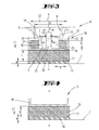
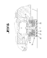
- Fig. 5 a further embodiment is shown, in which the soft tissue 25, starting from the loading surface 27, even without weight load by the extension 9, also extends laterally above the extension 9.
- the extension 9 in this case does not extend beyond the loading surface 27 also down.
- the extension 9 sits on the loading surface 27 by means of a hard part 28.
- the hard part 28 may, for example, be formed by a conventional washer.
- the soft tissue 25, as in the illustrated embodiment can extend to near or touching an outer surface of the extension 9.
- a radial distance for example, is preferred in the region of the wall thickness of the extension 9 which is formed there like a tube.
- the loading surface 27 that surface of a soft tissue is preferably addressed, which receives a weight force through the extension 9 by means of the lower free end face.
- the loading surface 27 receives the corresponding force by means of the step surfaces of the bottom 15.
- the force only indirectly, by means of the hard part 28 on.
- the embodiments of the FIGS. 9 and 10 nor an additional recording of the weight by the upper soft tissue or an upper portion of the soft tissue, introduced via a corresponding step surface of the bottom 15 of the extension 9, given.
- the introduction of the weight on the soft tissue 25 is also given only by the corresponding surface of the bottom (step portion) of the extension 9.
- the introduction of the weight force with respect to the upper soft tissue 26 by a force acting on this, preferably the soft tissue spanning total, surface of the housing bottom and the extension 9 is given.
- the extension 9 can preferably migrate to a certain extent on the hard part 28 in the lateral direction. Thus, corresponding movements of the food processor can be taken cheap.
- the standing part 12 here in the form of an elastomeric part formed. It is preferably glued to the shell portion 18 on the underside.
- the holder of the shell portion 18 on the extension 9 is preferred - and in the illustrated embodiment - according to the embodiment of Fig. 3 realized so that it can be referenced in more detail on this.
- the soft tissue 25 of the embodiment of the Fig. 5 made of a foam part, for example.
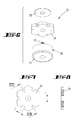
- a shaped section, in particular a foam blank, formed the single, evenly distributed over the circumference, outwardly standing projections 29 has.
- the extensions are clearly formed with an arrow-like outline contour.
- six extensions are provided evenly distributed over the circumference. Between the extensions, a distance i is formed in the circumferential direction. There are thus created valleys between the individual extensions 29. The distance i goes radially inward to a level that corresponds approximately to a largest free floor plan dimension of the bottom of the shell portion.
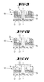
- FIG. 9 another embodiment is shown. It differs from the embodiment of the Fig. 5 in that the hard part 28 separates a first soft part 25 and, in this embodiment, a further soft part 26 arranged above it from one another. These are both Soft parts preferably by a respective annular part.
- the inner diameter of the upper soft tissue 26 is significantly larger. For example, the inner diameter is greater than the inner diameter of the lower soft part by the amount of the thickness (unloaded state) of the soft tissue 25 or 26.
- extension 9 While a lower region of the extension 9 extends into the upper soft part 26 in the region of the inner free space defined by said inner diameter and rests on the hard part 28, the soft tissue 25 is not penetrated by the extension 9.
- the extension 9 is further stepped in cross-section with respect to the upper soft tissue 26.
- a vertical step portion is in lateral overlap (inside) to the upper soft part 26, while the extension 9 by means of a horizontal step portion on the soft tissue 26 is seated (which forms a further loading area insofar).
- the embodiment of the Fig. 10 corresponds to the embodiment of the Fig. 9 However, although no hard part 28 is provided here. Rather, a lower end face of the extension 9 sits directly on the loading surface 27 of the lower soft tissue 25. Furthermore, as shown, the extension 9 is preferably also formed with a greater wall thickness, so that there is a lower surface pressure with regard to the soft tissue 25. A wall thickness may be 0.5 to 1.5 times, preferably approximately 1 times the vertical thickness of the soft tissue 25.
- Fig. 11 is merely a soft tissue, corresponding to the lower soft tissue 25 of the FIGS. 9 and 10 intended.
- This soft tissue is in the same way formed circular.
- the loading surface 27, the extension 9 sits directly on.
- a lateral influence of the extension 9 by the soft tissue 25 results here only according to the weight load and corresponding sinking of the extension 9 in the soft tissue 25.
- the inner diameter is relatively small. It is preferably adapted to the outer diameter of the pin 22.
- the wall thickness of the extension 9 is also chosen comparatively large here. Such that the lower end face, with which it rests on the soft tissue, designed comparatively large.
- the wall thickness may correspond to 0.5 to 1.5 times, preferably 1 times, the vertical thickness of the soft tissue 25. Due to the annular, continuous closed lower end face of the extension 9, this results in a desired (comparatively low) surface pressure to the soft tissue 25th
- the embodiment of the Fig. 12 corresponds in principle to the embodiment of Fig. 5
- the extension 9, here also with correspondingly preferably greater wall thickness sits directly with its lower end face on the loading surface 27 of the soft tissue 25.
- a step surface of the extension 9 (in the region of a bottom 15), which would also additionally rest on the upstanding region of the soft tissue 25 (whose end surface), is preferably not provided here.
- the soft tissue 25 may be formed as a foam-shaped section directly adapted to the interior of the shell portion 18. Here as in its three-dimensional shell-like form, for example. Immediately integrally produced (foamed or milled) soft tissue. But it can also according to the explanation of the Fig. 6 to 8 be formed with extensions or a continuous edge. The edge can be made by pressing in the Soft tissue 25 in the shell portion 18 to be bent or folded upwards.
- a step portion formed as in relation to the embodiment of Fig. 9 with respect to the interaction with the upper soft tissue 26 is described.
- the extension sits in an inner opening of the soft tissue 25, while it is seated with an upper step section directly on an upper loading surface 27 of the soft tissue 25.
- extension 9 is formed on the upper side in the form of a downwardly open shell portion, in which a second soft tissue 26 is received.
- This second soft part 26 is preferably supported in the same way, by means of a hard part 28, as in relation to Fig. 5 with respect to the holder of the soft tissue 25 in the shell portion 18 is described.
- the area ratios of the placement area of the projection 9 on the (lower) soft tissue 25 preferably are provided so that the weight force that is transmitted through the extension 9, at least in half, but preferably mostly, such as up to 3 ⁇ 4 or 8/9 only by the lower soft tissue 25 is recorded.
- the upper soft tissue 26 may primarily have the function of receiving displacements of the housing relative to the table surface or other support surface transversely to the effect of the weight.
- the hard part 28 is integrally formed integrally or fixedly connected to the pin 22, that there a large proportion of the weight is added.
- an inverse ratio can be achieved, namely, that said substantial part of the weight, even to the extent mentioned, is actually taken up by the soft tissue 26, and the soft tissue 25 substantially or only for receiving said displacement tendencies across the effect of Gravity serves.
- the force transmitting end face of the extension 9 may also be formed significantly larger than it in the Fig. 13 is shown.
- a vertical distance s between the loading surfaces of the lower soft tissue 25 and the upper soft tissue 26 is preferably 1 ⁇ 4 of the outer diameter d, as in Fig. 3 is reduced (2 times) by the distance e, up to half,% or a whole corresponding dimension.
Landscapes
- Engineering & Computer Science (AREA)
- General Engineering & Computer Science (AREA)
- Mechanical Engineering (AREA)
- Food Science & Technology (AREA)
- Food-Manufacturing Devices (AREA)
- Springs (AREA)
Abstract
Description
- Die Erfindung betrifft einen Standfuß eines Gerätes, insbesondere einer Tisch-Küchenmaschine, wobei das Gerät ein Gehäuse mit einem bei üblicher Aufstellung nach unten abragenden Fortsatz aufweist, der auf einem eine Standfläche ausbildenden Standteil unter Zwischenlage eines Weichteils aufsitzt, wobei das Weichteil in einem nach oben offenen Schalenabschnitt des Standteils aufgenommen ist und der in den Schalenabschnitt hineinragende Fortsatz auch quer zu einer Einfederungsbewegung durch eine Gewichtskraft des Gerätes beweglich in dem Schalenabschnitt aufgenommen ist, wobei weiter das Weichteil eine obere Beaufschlagungsfläche für den Fortsatz bildet.
- Im Weiteren betrifft die Erfindung einen Standfuß eines Gerätes, insbesondere einer Tisch-Küchenmaschine, wobei das Gerät ein Gehäuse mit einem bei üblicher Aufstellung nach unten abragenden Fortsatz aufweist, der auf einem eine Standfläche ausbildenden Standteil unter Zwischenlage eines Weichteils aufsitzt, wobei das Weichteil in einem nach oben offenen Schalenabschnitt des Standteils aufgenommen ist.
- Derartige Standfüße sind bereits in verschiedener Ausgestaltung bekannt geworden. Aus den
GB-A-13 78 758 - Aus der
US-A-3 717 318 ist ein Standfuß bekannt, bei welchem in vergleichbarer Weise eingeschachtelt übereinander angeordneten Schalenteile vorgesehen sind, die jeweils nach unten öffnen. Im Unterschied zu dem vorbeschriebenen Stand der Technik ist lediglich die Bewegung der Schalenteile quer zu einer durch eine Gewichtskraft gegebenen Einfederungsbewegung durch ein weiteres Weichteil gedämpft. - Darüber hinaus ist zum Stand der Technik auf die
EP-A1-2 659 810 zu verweisen. Bei dem hieraus bekannten Standfuß ist der in das Schalenteil hineinreichende Fortsatz auch quer zu einer Einfederungsbewegung durch eine Gewichtskraft des Gerätes beweglich in dem Schalenteil aufgenommen. Bei einer solchen Bewegung wirkt er zunächst und vorrangig unmittelbar mit dem in dem Schalenabschnitt aufgenommenen Weichteil zusammen. Ohne Wirkung einer Gewichtsbelastung durch das Gerät sitzt der Fortsatz nur auf einer Beaufschlagungsfläche des Weichteils auf und erstreckt sich in einem weiteren Bereich seitlich zu dem sich nach unten bezüglich der Aufsatzfläche anschließenden Bereichs des Weichteils. In dem weiteren Bereich ist stirnseitig des Fortsatzes keine Ausbildung des Weichteils vorgesehen. - Ausgehend von dem vorbeschriebenen Stand der Technik beschäftigt sich die Erfindung mit der Aufgabenstellung eine im Hinblick auf Dämpfung von Bewegungen günstige Ausgestaltung eines Standfußes anzugeben.
- Diese Aufgabe ist nach einer ersten Lehre der Erfindung beim Gegenstand des Anspruches 1 gelöst, wobei darauf abgestellt ist, dass das Weichteil, ausgehend von der Beaufschlagungsfläche, auch ohne Gewichtsbelastung durch den Fortsatz, auch oben seitlich zu dem Fortsatz ausgebildet ist.
- Hiermit ist gleichsam eine auch schalenartige Gestaltung des Weichteils angegeben. Der Fortsatz ist endseitig über seine Länge auch bezüglich des lediglich auf der Beaufschlagungsfläche aufsitzenden Teils von dem Weichteil umgeben. Derselbe Teil des Fortsatzes ist dem genannten Bereich seitlich zu einer Wirkungsrichtung der Gewichtskraft und vertikal in Richtung der Gewichtskraft durch das Weichteil abfederbar. Es bedarf keines gesonderten Teils des Fortsatzes, der sich gegenüber der genannten Beaufschlagungsfläche - wiederum betrachtet ohne Gewichtsbelastung - weiter nach unten erstreckt. Der Fortsatz kann sich in dem genannten Bereich relativ zu dem Weichteil, auch relativ zu dem sich seitlich zu dem Fortsatz, oberhalb der Beaufschlagungsfläche, erstreckenden Bereich des Weichteils bewegen. Der Fortsatz ist mit dem Weichteil in dem genannten Bereich nicht verbunden, so dass eine Bewegung in einer Richtung quer zu der Einfederungsbewegung durch die Gewichtskraft zwar zu einem Zusammendrücken des sich seitlich zu dem Fortsatz in dem genannten Bereich erstreckenden Bereiches des Weichteils führen kann, nicht jedoch zugleich gegenüberliegend zu einer Zugbelastung auf das Weichteil.
- Die Aufgabe ist weiterhin auch beim Gegenstand des Anspruches 2 gelöst, wobei darauf abgestellt ist, dass der Fortsatz auf dem Weichteil mittels eines von dem Weichteil unter seitlicher Umfassung klemmgehalterten Hartteils aufsitzt. Auch hierdurch ist zunächst die seitliche Erstreckung des Weichteils im Hinblick auf den von oben aufsitzenden Fortsatz erreicht. Zugleich aber auch eine günstige Montage durch die ledigliche Klemmhalterung des Hartteils durch das Weichteil. Zwar ist in einem Benutzungszustand des Gerätes durch die Befestigung des Standfußes mittels des Fortsatzes an dem Gerät auch letztlich eine Halterung des Hartteils gegeben. Im Zuge der Montage ist aber das Hartteil schon an dem Schalenteil gehaltert, ohne dass es besonderer Maßnahmen bedarf. Es liegt eine günstige Vormontage der Baugruppe Schalenteil, Weichteil und Hartteil vor.
- Diese Aufgabe ist auch beim Gegenstand des Anspruches 3 gelöst, wobei darauf abgestellt ist, dass das Weichteil mehrteilig ausgebildet ist und das ein weiterer Teil in einem nach unten offen Schalenabschnitt des Fortsatzes aufgenommen ist.
- Darüber hinaus ist die Aufgabe beim Gegenstand des Anspruches 4 gelöst, wobei darauf abgestellt ist, dass das Weichteil eine freie Bodenfläche des Schalenteils vollständig ausfüllt und nur zufolge Deformation bei Gewichtsbelastung sich auch oben seitlich zu dem Fortsatz erstreckt.
- Weitere Merkmale der Erfindung sind nachstehend, auch in der Figurenbeschreibung und der Zeichnung offenbart.
- Es ist im Weiteren bevorzugt, dass eine seitliche Zusammenwirkung des Fortsatzes mit dem Weichteil, soweit ein Hartteil vorgesehen ist, nur oberhalb des Hartteils ermöglicht ist. Der Fortsatz durchsetzt entsprechend das Hartteil bevorzugt nicht. Er sitzt vielmehr weiter bevorzugt lediglich reibschlüssig auf dem Hartteil auf.
- Das Weichteil kann ausgehend von einem Scheibenteil gebildet sein, wobei ein Randbereich des Scheibenteils, soweit eine Erstreckung auch oberhalb der Beaufschlagungsfläche gegeben ist, im Benutzungszustand hochgeklappt ist. Somit kann ausgehend von einem einstückigen Teil, bspw. einem einstückigen Stanzteil, bspw. einem Schaumstoff-Stanzteil, das auch in der genannten seitlichen Richtung den Fortsatz umgreifende Weichteil bereitgestellt sein.
- Der Randbereich des so gebildeten Weichteils weist bezogen auf den Herstellungszustand des Weichteils, also einen scheibenförmigen Zustand, bevorzugt nach radial außen vorstehende Fortsätze auf. Die Fortsätze können über den Umfang gleich ausgebildet sein und/oder über den Umfang gleich verteilt vorgesehen sein. Alle Fortsätze können zueinander gleich ausgebildet sein. Weiter bevorzugt sind die Fortsätze in Umfangsrichtung mit einem Umfangsabstand ausgebildet. Der Umfangsabstand kann bspw., wenn die Fortsätze verzahnungsartig gebildet sind, durch Täler zwischen einzelnen Zähnen gegeben sein. Das Weichteil ist in einem ersten Abschnitt, betrachtet im Einbauzustand, an einen Bodengrundriss des Schalenteils angepasst. Dieser Bodengrundriss und damit bevorzugt der erste Abschnitt sind bspw. kreisförmig. Weiter bevorzugt sind die Fortsätze ausgehend von einem solchen größten Bodengrundriss-Maß, im Falle des Kreises also ausgehend von einem größten Radius des Bodengrundriss, gebildet. Radial nach außen anschließend an den Radius erstrecken sich in diesem Fall im Herstellungszustand des Weichteils die einzelnen Fortsätze. Diese Fortsätze bilden entsprechend einen zweiten Abschnitt des Weichteils. Durch das Hochklappen ist bevorzugt erreicht, dass die Fortsätze im Einbauzustand in Umfangsrichtung zumindest über einen Teil ihrer Erstreckung, in diesem Einbauzustand also in ihrer Erstreckung nach oben, in Anlage aneinander sind.
- Das Weichteil kann aus dem schon genannten Schaumstoff bestehen. Bevorzugt besteht es insofern aus einem Weichschaumstoff. Der Schaumstoff kann offenporig gebildet sein. Im Übrigen wird auf die weiteren Ausführungen nachstehenden hinsichtlich des Weichteils auch verwiesen.
- Das Hartteil kann aus einem metallischen Werkstoff bestehen. Es kann bspw. ein Stahlteil sein. Das Hartteil weist gegenüber dem Weichteil, bezogen auf dessen unverformten Zustand bevorzugt eine geringe Dicke auf. Weiter bevorzugt ist die Dicke 1/3 des Hartteils oder weniger bis hin zu 1/10 oder 1/20 der Dicke des Weichteils im unverformten Zustand. Beispielsweise kann das Hartteil unabhängig von der genannten Dicke als übliche Unterlegscheibe gebildet sein.
- Das Standteil kann einen Halterungsvorteil aufweisen, der mit dem Fortsatz des Gerätes zur Halterung des Standteils verbindbar ist bzw. im Nutzungszustand verbunden ist. Der Halterungsfortsatz kann bezogen auf einen Querschnitt mittig ausgebildet sein. Er kann sich bezüglich des Fortsatzes des Gerätes zu diesem innen erstrecken. Hierzu kann der Fortsatz bspw. zylinderartig oder in sonstiger Form als Hohlkörper, etwa auch im Sinne eines Vierkant- oder Mehrkantrohres, ausgebildet sein.
- Das Standteil kann mit dem Fortsatz zur verliersicheren Halterung formschlüssig zusammenwirken. Auch kann der Fortsatz in dem Schalenabschnitt unter vertikaler Überdeckung zu dem Schalenabschnitt aufgenommen sein. Der Formschluss kann durch eine Übergreifscheibe erreicht sein. Die Übergreifscheibe kann an dem Halterungsfortsatz bspw. formschlüssig befestigt sein, bspw. durch eine Rastbefestigung, und an dem Fortsatz bspw. durch Aufliegen.
- Das Weichteil kann auch mehrteilig ausgebildet sein. Insbesondere kann es einerseits, als erstes Teil, die Beaufschlagungsfläche für den Fortsatz in Richtung der wirkenden Gewichtskraft bilden und als zweites Teil, zunächst mit radialem bzw. seitlichem Abstand zu dem Fortsatz, einem Bereich, bei welchem der Fortsatz bei Verlagerung quer zur wirkenden Gewichtskraft zur Anlage kommen kann. Die beiden Teile des Weichteils können durch das Hartteil getrennt sein. Ein weiteres Teil des Weichteils kann auch in einem nach unten offenen Schalenabschnitt des Fortsatzes aufgenommen sein. Auch hier kann es mit Hilfe eines Hartteils, grundsätzlich wie vorstehend zu dem Schalenabschnitt des Standteils beschrieben, klemmgehaltert sein.
- Die insgesamt beschriebene mögliche Mehrteiligkeit des Weichteils kann auch dahingehend genutzt sein, dass Weichteile mit unterschiedlich eingestellter Härte angeordnet sind. Beispielsweise kann die Härte sich um 10 oder mehr Prozent unterscheiden, bis bspw. bis zu 100 %.
- Eine weitere mögliche Lösung der Aufgabe ist nach einem Erfindungsgedanken bei einem Standfuß gegeben, bei welchem darauf abgestellt ist, dass das Standteil aus einem gummiartigen Weichmaterial besteht, dass das unmittelbar mit dem Standteil verbundene Weichteil aus einem Schaumstoff, bspw. PUR-Schaumstoff, besteht, und dass eine in Richtung einer von dem Standfuß aufgenommenen Gewichtskraft gemessene Dicke des Weichmaterials dem Zwei- oder Mehrfachen bis hin zu einem Zwanzigfachen der Dicke des Standteiles entspricht. Das Standteil ist bevorzugt zumindest im Bereich dessen Standfläche gummiartig ausgebildet, was weiter insbesondere einem Versetzen bzw. Verschieben der Küchenmaschine mit dessen Standfüßen relativ zur Abstellfläche, bspw. Tischfläche, entgegen wirkt.
- Das aus einem Weichmaterial bestehende Standteil ist weiter bevorzugt unmittelbar mit dem Weichteil verbunden, bspw. mit diesem verklebt oder verschweißt. Das Weichteil ist bevorzugt ein Schaumstoff, weiter insbesondere ein Polyuretan-Schaumstoff. Entsprechend weist das Weichteil gute Dämpfungseigenschaften insbesondere hinsichtlich über den Fortsatz oder den Gehäuseabschnitt aus der Küchenmaschine heraus auf den Standfuß übertragene Stöße.
- Mit Bezug auf die Richtung der auf den Standfuß, insbesondere auf das Standteil einwirkenden Gewichtskraft der Küchenmaschine, weiter mit Bezug auf eine senkrecht zur Standfläche des Standteiles betrachtete Richtung, weist das Weichteil eine Dicke auf, die eine ausreichende Dämpfung von insbesondere vertikal eingeleiteten Stößen bietet, sowie quer zur Dickenrichtung des Weichteils betrachtete Horizontaldeformationen erlaubt. Das an dem Weichteil unmittelbar befestigte gummiartige Standteil verhindert hierbei, dass das Weichteil durch Reibung zur Aufstellfläche der Küchenmaschine, bspw. bei einem Verschieben des Gerätes, beschädigt wird.
- Die Dicke des Weichteils entspricht bevorzugt dem Zwei- bis Zwanzigfachen der Dicke des Standteiles, weiter bevorzugt dem Sechs- bis Zwölffachen. Weiter bevorzugt kommt ein Weichteil zum Einsatz mit einer Dicke von bevorzugt mehr als 5 mm, weiter bevorzugt mehr als 6 mm bis hin zu 30 mm.
- Die Ausführungen insbesondere hinsichtlich des Weichteils, die enthalten sind, können für alle hier beschriebenen Ausführungsformen Bedeutung haben.
- Weiter bevorzugt ist das Standteil ein Elastomerteil, entsprechend bevorzugt ein formfestes, jedoch elastisch verformbares Weichkunststoffteil, welches Rückstelleigenschaften aufweist.
- In weiter bevorzugter Ausgestaltung ist der Fortsatz oder Gehäuseabschnitt der Küchenmaschine mit dem ersten Weichteil unmittelbar verbunden. So ist diesbezüglich bevorzugt eine Klebeverbindung oder eine Schweißverbindung.
- Auch ist in diesem Zusammenhang bevorzugt, den Gehäuseabschnitt zugewandt dem ersten Weichteil als Flächenteil auszugestalten, wobei weiter bevorzugt eine unmittelbare Verbindung zwischen Gehäuseabschnitt und Weichteil über diese Fläche erfolgt. Es ergibt sich in bevorzugter Ausgestaltung eine sandwichartige Ausformung des Standfußes, mit in Richtung der von dem Standfuß aufgenommenen Gewichtskraft betrachtete Anordnung von Gehäuseabschnitt, Weichteil und Standteil.
- In alternativer Ausgestaltung ist ein weiteres - im oben beschriebenen Sinne handelt es sich um ein erstes - Weichteil vorgesehen, das in einem nach oben offenen Schalenabschnitt aufgenommen ist, wobei der Fortsatz oder Gehäuseabschnitt auf dem weiteren Weichteil aufsitzt. Der nach oben offene Schalenabschnitt bildet insbesondere eine bevorzugt umlaufende Begrenzung eines durch den Schalenabschnitt gegebenen Ausweichraumes für das weitere Weichteil. Dieses Weichteil kann bei Bewegungen des Fortsatzes oder des Gehäuseabschnittes relativ zu dem Standteil im Überdeckungsbereich zu dem Fortsatz oder Gehäuseabschnitt zwischen dem Fortsatz oder Gehäuseabschnitt und der Wand des Schalenabschnittes komprimiert werden.
- Das weitere Weichteil ist hierbei bevorzugt unverlierbar, weiter bevorzugt aber ohne stoffschlüssige Verbindung, in dem Schalenabschnitt angeordnet.
- Weiter bevorzugt ist das weitere Weichteil hinsichtlich seiner Shorehärte so eingestellt, dass der geräteseitige Fortsatz oder Gehäuseabschnitt bei üblichem Maximalgewicht der Küchenmaschine das Weichteil nicht derart komprimiert, dass sich ein gleichsam starrer Übergang ergibt. Vielmehr ist die Härte so gewählt, dass auch dann immer noch sich ein elastisches Einfedern einstellen kann.
- Bevorzugt ist weiter der Fortsatz oder Gehäuseabschnitt selbst gegenüber insbesondere dem weiteren Weichteil härter ausgebildet, insbesondere durch Ausbildung des Fortsatzes oder Gehäuseabschnittes aus Hartkunststoff oder Metall.
- Der Schalenabschnitt sitzt in bevorzugter Ausgestaltung auf dem weiteren, unteren Weichteil auf. Der Schalenabschnitt, insbesondere dessen Bodenabschnitt ist entsprechend sandwichartig gefasst zwischen dem zweiten und dem ersten Weichteil.
- Bevorzugt ist das weitere Weichteil kreisringförmig ausgebildet, was eine günstige Deformation des weiteren Weichteiles, insbesondere quer zu einer Gewichtskraft-Richtung und die entsprechende Rückstellfähigkeit unterstützt.
- Das weitere Weichteil und/ oder das Standteil sind in bevorzugter Ausgestaltung kreisscheibenförmig ausgebildet. Auch sind diesbezüglich andere, bevorzugt durchgehend plattenförmige Ausgestaltungen von unterem Weichteil und Standteil möglich, so bspw. einen mehreckigen Grundriss aufweisend. Insbesondere bei kreisscheibenförmiger Ausgestaltung des unteren Weichteils und/oder des Standteils ist ein Außendurchmesser gewählt, der dem Außendurchmesser des gegebenenfalls auf dem unteren Weichteil aufsitzenden Schalenabschnittes entspricht.
- Bezüglich des einen oder beider Weichteile handelt es sich bevorzugt um einen offenporigen oder geschlossenporigen Schaumstoff, wobei geschlossenporiger Schaumstoff insbesondere im Zusammenhang bei einer Küchenmaschine Vorzüge aufweist.
- Von Bedeutung ist auch, dass das eine oder beide Weichteile bevorzugt insgesamt, insbesondere in den ggf. durch den Fortsatz oder den Gehäuseabschnitt beaufschlagten Bereich, weicher eingestellt ist als das bevorzugt aus einem gummiartigen Weichmaterial bestehende Standteil. Das oder die Weichteile weisen entsprechend eine geringere Shorehärte auf als das Standteil.
- Bevorzugt ist das Material des einen oder beider Weichteile und die Überdeckung des Fortsatzes bzw. Gehäuseabschnittes zu einem der Weichteile so gewählt bzw. eingestellt, dass sich bei einer Verschiebung von einem Millimeter bezüglich aller auf einer Unterlage aufstehenden Standfüße der Küchenmaschine (bevorzugt: vier Standfüße) eine Rückstellkraft von 5 N oder mehr bis hin zu bevorzugt 15 N, weiter bevorzugt etwa 10 N einstellt.
- Zudem ist diesbezüglich bevorzugt, dass mit zunehmender Horizontalverschiebung der in Überdeckung zu den Weichteilen oder dem einen Weichteil liegenden Fortsätzen bzw. Gehäuseabschnitten die Rückstellkraft insbesondere des einen oder der mehreren Weichteile (jeweils) überproportional zunimmt. So stellt sich bevorzugt bei einer Verdopplung der Horizontalverschiebung von einem Millimeter auf 2 mm eine Rückstellkraft ein, die dem 2,1- bis 3-fachen, weiter bevorzugt etwa dem 2,5-fachen des Rückstellwertes bei einem Millimeter entspricht. Bevorzugt ergibt sich bei einer Horizontalverschiebung von 2 mm eine Rückstellkraft des einen oder der beiden Weichteile von etwa 25 N. Entsprechend ist eine nicht-lineare Zunahme der Rückstellkraft vorgesehen.
- Ein Weichteil kann, wie angesprochen, aus einem Schaumstoff bestehen. Es kann hierbei nicht nur aus einem offenporigen oder geschlossenporigen, sondern auch aus einem gemischt-porigen Schaumstoff bestehen. Bevorzugt ist ein Polyurethan-Schaum, weiter bevorzugt ein gemischtzelliger Polyurethan-Schaumstoff mit teilweise geschlossenen und teilweise offenen Poren.
- Bevorzugt weist ein Weichteil eine Zugfestigkeit (Minimalwert nach DIN 53571) von 0,5 bis 1,5 N/mm2, weiter bevorzugt 0,56 bis 1,3 N/mm2 auf. In bevorzugter Ausgestaltung ist eine Zugfestigkeit von 0,78 N/mm2 vorgesehen.
- Weiter bevorzugt ist ein Weichteil so eingestellt, dass ich in Anlehnung an die EN 826 ein statistisches Elastizitätsmodul von 0,05 bis 1,3 N/mm2 einstellt, weiter bevorzugt 0,14 bis 0,75 N/mm2. Zudem ist ein dynamisches Elastizitätsmodul nach DIN 53513 von 0,3 bis 1,8 N/mm2, weiter bevorzugt 0,6 bis 1,3 N/mm2 vorgesehen.
- Die vor- und nachstehend angegebenen Bereiche bzw. Wertebereiche oder Mehrfachbereiche schließen hinsichtlich der Offenbarung auch sämtliche Zwischenwerte ein, insbesondere in 1/10-Schritten der jeweiligen Dimension, ggf. also auch dimensionslos, insbesondere 1,01-fach etc., einerseits zur Eingrenzung der genannten Bereichsgrenzen von unten und/oder oben, alternativ oder ergänzend aber auch im Hinblick auf die Offenbarung eines oder mehrerer singulärer Werte aus dem jeweils angegebenen Bereich.
- Nachstehend ist die Erfindung anhand der beigefügten Zeichnung erläutert, die aber lediglich Ausführungsbeispiele darstellt. Ein Teil, das nur bezogen auf eines der Ausführungsbeispiele erläutert ist und bei einem weiteren Ausführungsbeispiel aufgrund der dort herausgestellten Besonderheit nicht (gerade) durch ein anderes Teil ersetzt ist, ist damit auch für dieses weitere Ausführungsbeispiel als jedenfalls mögliches vorhandenes Teil beschrieben. Auf der Zeichnung zeigt:
- Fig. 1
- in perspektivischer Darstellung eine Tisch-Küchenmaschine mit Standfüßen zum Aufstellen der Küchenmaschine auf einer Tischfläche;
- Fig. 2
- eine perspektivische, teilweise aufgebrochene Darstellung eines Bodenbereiches der Küchenmaschine mit einem Standfuß in einer ersten Ausführungsform;
- Fig. 3
- den Schnitt gemäß der Linie III-III in
Fig. 2 , eine im Wesentlichen unbelastete Grundstellung des Standfußes betreffend; - Fig. 4
- eine der
Fig. 3 entsprechende Darstellung, eine zweite Ausführungsform des Standfußes betreffend; - Fig. 5
- eine weitere Querschnittsansicht des unteren Bereichs der Küchenmaschine mit angebrachtem Standfuß;
- Fig. 6
- den Standfuß gemäß
Fig. 5 in Exposionsdarstellung; - Fig. 7
- eine Draufsicht auf das Weichteil des Standfuß gemäß
Fig. 5 bzw.Fig. 6 ; - Fig. 8
- einen Querschnitt durch den Gegenstand der
Fig. 7 , geschnitten entlang der Linie VIII-VIII; - Fig. 9
- eine Querschnittsansicht eines Standfußes in weiterer Ausführungsform;
- Fig. 10
- eine Querschnittsansicht eines Standfußes in weiterer Ausführungsform;
- Fig. 11
- eine Querschnittsansicht eines Standfußes in weiterer Ausführungsform;
- Fig. 12
- eine Querschnittsansicht eines Standfußes in weiterer Ausführungsform und
- Fig. 13
- eine Querschnittsansicht eines Standfußes in weiterer Ausführungsform.
- Dargestellt und beschrieben ist zunächst mit Bezug zu
Fig. 1 eine Küchenmaschine 1 mit einer Rührgefäß-Aufnahme 2 und einem Bedienfeld 3. - Der Küchenmaschine 1 ist ein Rührgefäß 4 zugeordnet. Dieses sitzt in der Rührgefäß-Aufnahme 2 ein. In dem Rührgefäß 4 ist zugeordnet einem Rührgefäßboden bevorzugt ein Rührwerk vorgesehen, welches über einen in der Küchenmaschine 1 unterhalb der Aufnahme 2 angeordneten, nicht dargestellten Elektroantrieb antreibbar ist.
- Das Gehäuse 5 der Küchenmaschine 1 stützt sich über Standfüße 6 auf einer Fläche, hier einer Tischfläche 7, ab. Die Standfüße 6 sind hierzu unterseitig eines Gehäusebodens 8 befestigt.
- Die Küchenmaschine 1 ist unter anderem geeignet zur Herstellung von Teigen. In einem solchen Teigmodus wird mit dem sich drehenden Rührwerk durch die Zähigkeit des Teiges ein hoher Widerstand entgegengesetzt. Das erforderliche Antriebsmoment des Motors wird, natürlich bei sonstigem Motorbetrieb auch, über das Gehäuse 5 und die Standfüße 6 abgestützt. Ist die Teigkugel ungünstig im Rührgefäß 4 angeordnet, bleibt das Rührwerk ggf. kurzzeitig im Teig stecken. Zufolge dessen wird das Drehmoment kurzzeitig erhöht. Auch ein solcher Momentenstoß wird von den Standfüßen 6 kompensiert, so dass sich das Gerät nicht ruckartig und sprunghaft um seinen Schwerpunkt dreht. Darüber hinaus und unabhängig hiervon werden über die Standfüße 6 Vibrationen bzw. insbesondere vertikale Stöße in Richtung auf die Tischfläche 7 kompensiert.
- Die Bewegung des Gehäuses 5 in horizontaler Richtung (vgl. Pfeile a und b in
Fig. 1 ) wird zugelassen. Das Gehäuse 5 kann sich relativ zu den Standfüßen 6 bzw., wie nachstehend näher erläutert, relativ zu einem Teilabschnitt der Standfüße 6 in der horizontalen Ebene bewegen. Die gegebenenfalls sprungartig eingeleitete Energie wird in Reibung und/ oder Rückstell- und Verformungsenergie umgewandelt. Die Standfüße 6 sind hierbei bevorzugt auf der Standfläche - hier der Tischfläche 7 - nur aufsitzend und durch Reibschluss an einer Bewegung relativ zu der Standfläche gehindert. Darüber hinaus sind durch die Ausgestaltung der Standfüße 6 zudem auch relative Vertikalbewegungen des sich über die Standfüße 6 abstützenden Gehäuses 5, insbesondere relativ zu einem Teilabschnitt der Standfüße 6 gegeben. - Jeder Standfuß 6 ist im Wesentlichen zweiteilig gestaltet, wobei ein Teil gehäusefest vorgesehen ist. Bei diesem gehäusefesten Teil handelt es sich bevorzugt um einen Fortsatz 9 oder einen Gehäuseabschnitt 10, der gehäuseseitig, insbesondere gehäusebodenseitig, aus- oder angeformt ist. Im Falle eines Fortsatzes 9 ragt dieser bevorzugt nach vertikal unten über die nach unten gerichtete Gehäusebodenfläche frei ab. In alternativer Ausgestaltung ist der Fortsatz 9 bevorzugt oberhalb des Gehäusebodens 8 mit einem Wiegebalken einer Wägevorrichtung bevorzugt starr verbunden, welcher Wiegebalken anderenends wiederum an dem Gehäuse, insbesondere gehäusebodenseitig angreift.
- Der Fortsatz 9 bzw. der Gehäuseabschnitt 10 ist als Starrteil ausgebildet, weiter bevorzugt zufolge einstückiger, materialeinheitlicher Ausgestaltung zusammen mit dem Gehäuseboden 8. Entsprechend kann es sich bei dem Fortsatz 9 oder dem Gehäuseabschnitt 10 um einen Hartkunststoff- oder Metallkörper handeln, der weiter bevorzugt mit Bezug auf eine zentral den Fortsatz 9 bzw. den Gehäuseabschnitt 10 durchsetzende Vertikalachse x rotationssymmetrisch ausgebildet ist. Neben der einstückigen Ausgestaltung ist weiter alternativ ein Fortsatz 9 oder Gehäuseabschnitt 10 vorgesehen, der unterseitig am Gehäuseboden 8 festlegbar, bspw. einschraubbar ist.
- In dem insbesondere in den
Figuren 2 und3 dargestellten ersten Ausführungsbeispielen sitzt der gehäuseseitige Fortsatz 9 im Wesentlichen auf einem eine Standfläche 11 ausbildenden Standteil 12 auf. - Der Fortsatz 9 ist im Wesentlichen als rotationssymmetrischer Hohlkörper gebildet, mit einer umlaufenden Fortsatzwandung 13. In die durch die Fortsatzwandung 13 umfasste Röhrenöffnung 14 ist mit vertikalem Abstand zur nach vertikal unten freien Randkante der Fortsatzwandung 13 ein Boden 15 einstückig und bevorzugt materialeinheitlich mit der Fortsatzwandung 13 eingezogen.
- An dem Boden 15 ist unterseitig, entsprechend nach vertikal unten gerichtet, ein konzentrisch zur Vertikalachse x angeordneter Röhrenabschnitt 16 angeformt, dessen nach vertikel unten weisende Stirnfläche über die durch die nach unten weisende freie Randkante der Fortsatzwandung 13 definierte Horizontalebene hinausragt. Ein vertikaler Abstand c zwischen der sich in einer Horizontalebene erstreckenden Stirnfläche des Röhrenabschnittes 16 und der Stirnrandkante der Fortsatzwandung 13 entspricht bevorzugt einem Halben bis einem Zehntel, weiter bevorzugt etwa einem Drittel des Außendurchmessers d der Fortsatzwandung 13 im Bereich des Bodens 15.
- Das freie radiale Abstandsmaß e zwischen der Wandungsaußenseite des Röhrenabschnittes 16 und der Wandungsaußenseite der Fortsatzwandung 13 im Bereich des Bodens 15 entspricht weiter bevorzugt etwa einem Halben bis einem Zehntel, weiter bevorzugt etwa einem Siebtel des Fortsatzwandungs-Außendurchmessers d.
- Der Röhrenabschnitt 16 ist zentral durchsetzt von einem kreiszylinderförmigen Durchbruch 17, welcher zugleich auch den Boden 15 durchsetzt.
- Weiter ist bevorzugt gemäß der ersten Ausführungsform ein nach vertikal oben offener Schalenabschnitt 18 vorgesehen. Dieser weist einen weiter bevorzugt kreisscheibenförmigen Schalenboden 19 und eine umlaufende, vorzugsweise zylinderförmige, Schalenwandung 20 auf. Die vertikale Höhe der Schalenwandung 20 entspricht bevorzugt im Wesentlichen dem vertikalen Erstreckungsmaß des Durchbruchs 17 in dem Fortsatz 9.
- Der Innendurchmesser f des Schalenabschnitts 18 entspricht bevorzugt dem 1,1-bis 1,4-fachen des Außendurchmessers d der Fortsatzwandung 13, womit sich in einer wie in
Fig. 3 dargestellten Grundausrichtung umlaufend zwischen der Fortsatzwandung 13 und der Schalenwandung 20 ein Ringspalt 21 einstellt. - Ausgehend von der schaleninnenseitigen Oberfläche des Schalenbodens 19 wächst ein bevorzugt im Querschnitt kreisscheibenförmiger und/oder zylindrischer Zapfen 22 aus. Dieser ist bevorzugt zentral zu dem Schalenabschnitt 18 angeordnet und einstückig, materialeinheitlich mit dem Schalenabschnitt 18 ausgeformt. Der Durchmesser g ist hierbei kleiner gewählt als der Innendurchmesser h des fortsatzseitigen Durchbruchs 17, wobei der Zapfen 22 den Durchbruch 17 durchtretend mit seiner nach vertikal oben weisenden Stirnfläche über die nach oben weisende Ebene des Fortsatzbodens 15 hinausragt. Bei konzentrischer Anordnung von Fortsatz 9 und Schalenabschnitt 18 ergibt sich zwischen dem Zapfen 22 und der Wandung des Durchbruchs 17 ein umlaufender Spalt, dessen Radialmaß bevorzugt gleich oder größer ist dem Radialmaß des Ringspaltes 21.
- Der Schalenabschnitt 18 ist an dem Fortsatz 9 formschlüssig gehaltert. Hierzu ist eine Übergreifscheibe 23 vorgesehen, welche zentral durchsetzt ist von dem Zapfen 22 und bevorzugt auf der nach oben weisenden Oberfläche des Bodens 15 aufliegt. Ein oberhalb der Übergreifscheibe 23 wandungsaußenseitig an dem Zapfen 22 vorgesehener Kragen 24, bevorzugt in Form eines Sprengringes oder dergleichen, fesselt den Schalenabschnitt 18 über die Übergreifscheibe 23 an dem Fortsatz 9, dies unter Ermöglichung einer vertikalen Beweglichkeit des Schalenabschnittes 18, relativ zu dem Fortsatz 9, ausgehend von der Darstellung in
Fig. 3 nach vertikal oben. - Bodenseitig des Schalenabschnittes 18 ist ein (ggf. zweites bzw. weiteres) Weichteil 25 vorgesehen. Dieses ist bevorzugt kreisringförmig gestaltet und besteht weiter bevorzugt aus einem Weichschaumstoff. Das Weichteil 25 sitzt in dem Schalenabschnitt 18 auf dem Schalenboden 19 auf und weist bevorzugt einen an den Innendurchmesser der Schalenwandung 20 angepassten Außendurchmesser auf. Der Innendurchmesser der Schalenwandung 20 ist vorstehend auch als größtes Bodengrundriss-Maß angesprochen. Der freie Innendurchmesser des Weichteiles 25 ist weiter bevorzugt angepasst an den Außendurchmesser des fortsatzseitigen Röhrenabschnittes 16, wobei weiter bevorzugt der Kreisring-Innendurchmesser des Weichteiles 25 etwa dem 1,01- bis 1,1-fachen des Röhrenabschnitt-Außendurchmessers entspricht.
- Das Weichteil 25 ist in einer bevorzugten Ausgestaltung lediglich durch Reib- oder Formschluss in dem Schalenabschnitt 18 gehalten. In alternativer Ausgestaltung ist auch eine Befestigung diesbezüglich möglich, bspw. zufolge Verklebung.
- Die vertikale Höhe des Weichteiles 25 entspricht weiter bevorzugt etwa zwei Dritteln der Höhe der Schalenwandung 18, wobei weiter auch vertikale Höhen des Weichteiles 25 von bevorzugt ein Fünftel bis sieben Achtel der Schalenwandungshöhe möglich sind.
- Die Anordnung ist weiter bevorzugt so gewählt, dass in einer unbelasteten Grundstellung gemäß der Darstellung in
Fig. 3 (und auch der Darstellungen in denFig. 9,10 und13 ) der Fortsatz 9 mit der nach unten weisenden freien Stirnrandkante der Fortsatzwandung 13 bzw. mit der Unterseite des Bodens 15 radial außerhalb des Röhrenabschnittes 16 auf der nach oben weisenden ringförmigen Oberfläche, der Beaufschlagungsfläche 27, des Weichteils 25 aufsitzt, während der Röhrenabschnitt 16 des Fortsatzes 9 in die Ringöffnung des Weichteiles 25 eintaucht, dies bevorzugt unter vertikaler Beabstandung der nach unten weisenden Röhrenabschnitt-Stirnfläche zur zugewandten Oberfläche des Schalenbodens 19 oder der Beaufschlagungsfläche 27 (Fig. 9,10 ) des Weichteils 25. Er kann auch unmittelbar aufsitzen (Fig. 9 auf dem Hartteil 28,Fig. 10 unmittelbar auf dem Weichteil). Diese Stellung ist weiter bevorzugt zudem die Teleskop-Auszugsstellung von Fortsatz 9 und Schalenabschnitt 18, in welcher Stellung sich der Zapfen 22 mit seinem Kragen 24 oberseitig auf der übergreifenden Scheibe 23 abstützt, welch' letztere wiederum bevorzugt auf der zugewandten Oberfläche des fortsatzseitigen Bodens 15 aufliegt. - Das Weichteil 25 ist hinsichtlich der Härte bevorzugt so eingestellt, dass dieses in einer Grundbelastung (unter Berücksichtigung eines maximalen Gesamtgewichts der Küchenmaschine 1 und bei nicht aktiviertem Rührwerk) bevorzugt nicht oder nur unwesentlich über die Fortsatzwandung 13 komprimiert wird.
- Der Schalenabschnitt 18 sitzt weiter bevorzugt auf einem (ersten bzw. weiteren) Weichteil 26 auf. Dieses kann auch durch das Standteil 12, das bevorzugt ein Elastomerteil ist (bspw. TPE) gegeben sein. Auch hierbei handelt es sich bevorzugt um einen Weichschaumstoff, weiter insbesondere Polyurethan-Schaumstoff. Der Schalenabschnitt 18 sitzt hierbei mit der nach unten weisenden glatten Fläche des Bodens 15 auf der zugewandten Fläche des Weichteils 26 bevorzugt vollflächig auf. Weiter bevorzugt sind der Schalenabschnitt 18 und das Weichteil 26 miteinander verhaftet, so insbesondere klebeverbunden.
- Das Weichteil 26 ist in einem Schnitt quer zur vertikalen Achse x bevorzugt gleichgestaltet wie der Schalenabschnitt 18, so dass hier bevorzugt eine kreisscheibenförmige Ausbildung des Weichteils 26 vorliegt. Der Durchmesser des Weichteils 26 entspricht in bevorzugter Ausgestaltung dem Außendurchmesser der Schalenwandung 20.
- Die in Richtung der von dem Standfuß 6 aufgenommenen Gewichtskraft (Pfeil r) betrachtete Dicke 1 des Weichteiles 26 entspricht bevorzugt einem Halben bis einem Achtel des Weichteil-Durchmessers, weiter bevorzugt etwa einem Viertel.
- Unterseitig, d.h. dem Schalenabschnitt 18 abgewandt, ist das Weichteil 26 mit dem schon genannten vorzugsweise plattenförmigen Standteil 12 versehen. Dieses Standteil 12 kann bevorzugt aus dem genannten TPE oder einem gummiartigen Weichmaterial, insbesondere in Form eines Elastomerteils bestehen.
- Das Standteil 12 weist bevorzugt denselben Durchmesser auf wie das Weichteil 26.
- Die in Pfeilrichtung r betrachtete Dicke m des Standteiles 12 ist hierbei so gewählt, dass die Dicke 1 des Weichteiles 26 dem Zwei- bis Zwanzigfachen der Dicke m des Standteiles 12 entspricht, weiter bevorzugt etwa dem Vier- bis Fünffachen.
- Das Standteil 12 ist bevorzugt unmittelbar mit dem Weichteil 26 klebeverbunden.
- Auch bei der Ausführungsformen der
Fig. 5 bis 13 ist jeweils ein Standteil 12 bevorzugt verwirklicht. Hier weiter bevorzugt unmittelbar angebracht auf einer Unterseite bzw. einem Boden des Schalenabschnittes 18. - Eine bei üblichem Betrieb der Küchenmaschine 1 in der Regel auftretende Stoßbelastung wirkt in vertikaler als auch in horizontaler Richtung. Entsprechend ist das kreisringfömige Weichteil 25 in dem Schalenabschnitt 18 sowohl von vertikal oben durch die Fortsatzwandung 13 als auch von radial innen nach radial außen im Bereich der Weichteil-Kreisringöffnung durch den Röhrenabschnitt 16 beaufschlagt.
- Der Fortsatz 9 ist insgesamt in allen stoßrelevanten Richtungen durch das Weichteil 25 gedämpft gelagert, wobei das Weichteil 25 bevorzugt so ausgelegt ist, dass dieses über die elastischen Rückstellfähigkeiten den Fortsatz 9 jeweils tendenziell in die Ausgangsposition gemäß
Fig. 3 drängt. Weiter ist die Härte des Weichteiles 25 so gewählt, dass bei üblichen vertikalen Stoßbelastungen insbesondere bei ordnungsgemäßem Gebrauch der Küchenmaschine 1, d.h. weiter bei ordnungsgemäßer Maximalbefüllung des Rührgefäßes 4, die nach vertikal unten weisende freie Stirnfläche des Röhrenabschnittes 16 auch in der Maximalbelastung einen vertikalen Abstand zu der zugewandten Oberfläche des Schalenbodens 19 einhält. - Der Schalenabschnitt 18 wiederum ist insgesamt in allen stoßrelevanten Richtungen durch das Weichteil 26 gedämpft gelagert. Auch das Weichteil 26 ist bevorzugt so ausgelegt, dass dieses über die elastischen Rückstellfähigkeiten den Schalenabschnitt 18 jeweils tendenziell in die Ausgangsposition gemäß0
Fig. 3 drängt. - Durch die Anordnung insbesondere des Weichteiles 26 sowie die bevorzugte unmittelbare Befestigung des Weichteils 26 mit dem Schalenboden 19, weiter bevorzugt auch mit dem Standteil 12, ist die Standsicherheit der Küchenmaschine 1 insgesamt verbessert, wobei das gummiartige Standteil 12 verhindert, dass das Weichteil 26 durch Reibung relativ zur Tischfläche 7 bspw. beim Verschieben der Küchenmaschine 1 beschädigt wird.
- Die nach unten weisende Fläche des Standteiles 12 bildet hierbei die Standfläche 10 zur Zusammenwirkung mit bspw. der Tischfläche 7.
-
Fig. 4 zeigt eine alternative Ausführungsform des Standfußes 6. Hier ist ein sandwichartiger Aufbau bevorzugt. Bei einer bevorzugt insgesamt rotationssymmetrischen Ausgestaltung des Standfußes 6 mit Bezug zu einer Vertikalachse x ergeben sich auch in dieser Ausführungsform ein kreisscheibenförmiges Standteil 12, welches im Bereich einer ebenen Fläche unmittelbar mit einem kreisscheibenförmigen Weichteil 26 in Form eines Schaumstoffteiles verbunden ist. Auch hier ist diesbezüglich eine Klebeverbindung bevorzugt. - Das Weichteil 26 ist mit seiner dem Standteil 12 abgewandten Oberfläche unmittelbar und mit einem Gehäuseabschnitt 10 der Küchenmaschine 1 verbunden. Bevorzugt kommt hier eine Klebeverbindung zum Einsatz.
- Der Gehäuseabschnitt 10 weist bevorzugt dem Weichteil 26 zugewandt eine ebene Fläche auf, insbesondere zur vollflächigen Verklebung mit dem Weichteil 26.
- In bevorzugter Ausgestaltung ist der Gehäuseabschnitt 10 Teil des Gehäusebodens 8, erstreckt sich hierbei bevorzugt unterhalb einer allgemeinen nach unten weisenden Bodenebene. Gemäß dem vorbeschriebenen Ausführungsbeispiel kann sich der Gehäuseabschnitt 10 wie der Fortsatz 9 auch oberhalb der Bodenebene erstrecken und hierbei Teil bspw. eines Wiegebalkens sein.
- In Pfeilrichtung r betrachtet ist eine Dicke 1 des Weichteiles 26 von mindestens 6 mm bis hin zu 30 mm bevorzugt. Bezüglich der Dickenverhältnisse von Weichteil und Standteil 12 wird auf die Ausführungen zu dem zuvor beschriebenen Ausführungsbeispiel verwiesen. Unabhängig hiervon oder in Kombination hierzu kann das Weichteil 25 eine Dicke von 2 bis 10 mm aufweisen.
- Anstelle des Standteils 12 in Form eines gummiartigen Weichmaterials ist in einer weiteren Ausführungsform der Weichschaum des Weichteiles 26 zumindest auf der der Auflagefläche - hier Tischfläche 7 - zugewandten Seite verhautet oder alternativ mit einer entsprechenden Kunststoffhaut überzogen. Diese Haut verhindert eine Beschädigung des Schaumstoffes bei einem Verschieben des Gerätes auf der Tischfläche 7. Im Sinne der Erfindung bildet die Haut das Standteil 12 mit der Standfläche 11 aus.
-
Fig. 5 ist eine weitere Ausführungsform wiedergegeben, bei welcher das Weichteil 25 ausgehend von der Beaufschlagungsfläche 27, auch ohne Gewichtsbelastung durch den Fortsatz 9, sich auch oben seitlich zu dem Fortsatz 9 erstreckt. Der Fortsatz 9 reicht hierbei nicht über die Beaufschlagungsfläche 27 hinaus nach unten. In weiterer Einzelheit sitzt der Fortsatz 9 auf der Beaufschlagungsfläche 27 mittels eines Hartteils 28 auf. Das Hartteil 28 kann bspw. durch eine übliche Unterlegscheibe gebildet sein. Oberhalb des Hartteils 28 kann das Weichteil 25 wie in dem dargestellten Ausführungsbeispiel bis nahe an oder berührend an einer Außenfläche des Fortsatzes 9 reichen. Bevorzugt ist jedoch ein radialer Abstand, bspw. im Bereich der Wandstärke des dort röhrenartig gebildeten Fortsatzes 9. - Mit der Beaufschlagungsfläche 27 ist vorzugsweise diejenige Fläche eines Weichteils angesprochen, die eine Gewichtskraft durch den Fortsatz 9 mittels dessen unterer freier Stirnfläche aufnimmt. Bei der Ausführungsform der
Fig. 3 nimmt die Beaufschlagungsfläche 27 allerdings die entsprechende Kraft mittels der Stufenflächen des Bodens 15 auf. Bei den Ausführungsformen derFig. 5 und9 nimmt das Weichteil 25 mittels seiner Beaufschlagungsfläche 27 die Kraft auch nur mittelbar, vermittels des Hartteils 28 auf. Zudem ist bei den Ausführungsformen derFig. 9 und 10 noch eine zusätzliche Aufnahme der Gewichtskraft durch das obere Weichteil oder einen oberen Abschnitt des Weichteils, eingeleitet über eine entsprechende Stufenfläche des Bodens 15 des Fortsatzes 9, gegeben. - Bei der Ausführungsform der
Fig. 13 ist die Einleitung der Gewichtskraft auf das Weichteil 25 auch nur durch die entsprechende Fläche des Bodens (Stufenabschnitt) des Fortsatzes 9 gegeben. Zusätzlich ist die Einleitung der Gewichtskraft bzgl. des oberen Weichteils 26 durch eine auf diese einwirkende, vorzugsweise das Weichteil insgesamt überspannende, Fläche des Gehäusebodens bzw. des Fortsatzes 9 gegeben. - Der Fortsatz 9 kann bevorzugt auf dem Hartteil 28 in seitlicher Richtung im gewissen Ausmaß wandern. Somit können entsprechende Bewegungen der Küchenmaschine günstig aufgenommen werden.
- Im Weiteren ist auch beim Ausführungsbeispiel der
Fig. 5 unterhalb des Schalenabschnittes 18 das Standteil 12, hier in Form eines Elastomerteiles, ausgebildet. Es ist bevorzugt mit dem Schalenabschnitt 18 unterseitig verklebt. - Die Halterung des Schalenabschnittes 18 an dem Fortsatz 9 ist bevorzugt - und auch bei dem dargestellten Ausführungsbeispiel - entsprechend der Ausführungsform der
Fig. 3 realisiert, so dass in weiterer Einzelheit hierauf verwiesen werden kann. - Wie sich im Weiteren aus den
Figuren 6 bis 8 ergibt, ist das Weichteil 25 der Ausführungsform derFig. 5 aus einem Schaumstoffteil, bspw. hergestellt durch einen Formschnitt, insbesondere einem Schaumstoff-Stanzzuschnitt, gebildet, das einzelne, über den Umfang gleichmäßig verteilte, nach außen stehende Fortsätze 29 aufweist. Die Fortsätze sind in sich ersichtlich mit einer pfeilartigen Grundrisskontur gebildet. Über den Umfang sind mehrere, bei dem Ausführungsbeispiel sechs, Fortsätze gleichmäßig verteilt vorgesehen. Zwischen den Fortsätzen ist in Umfangsrichtung ein Abstand i ausgebildet. Es sind somit Täler zwischen den einzelnen Fortsätzen 29 geschaffen. Der Abstand i geht radial innen bis auf ein Maß, das etwa einem größten freien Grundrissmaß des Bodens des Schalenabschnitts entspricht. - Im Einbauzustand gemäß
Fig. 5 sind die Fortsätze 29 nach oben umgebogen oder geklappt. Aufgrund ihrer elastischen Rückstellkraft liegen sie an einer Innenfläche des Schalenabschnitts 18 an. Sie sind hierdurch zugleich aufgrund von Reibschluss in dem Schalenabschnitt gehaltert. Diese Halterung ist deutlich verstärkt durch die Wirkung des Hartteils 28, das zu einer vergleichsweisen starken Komprimierung im Bereich des Hartteils 28 (seitlich) führt. Dies aufgrund der bevorzugten Ausführung, dass ein Größtmaß des Hartteils 28, bei kreisförmiger Ausgestaltung also ein Außendurchmesser, ein Maß aufweist, das größer als es dem verbleibenden Innendurchmesser bei Umbiegung oder Abklappung des Weichteils nach oben entspricht. Somit ergibt sich in diesem Bereich eine besondere Verdichtung des Weichteils. - Mit Bezug zu
Fig. 9 ist eine weitere Ausführungsform dargestellt. Sie unterscheidet sich von der Ausführungsform derFig. 5 dadurch, dass das Hartteil 28 ein erstes Weichteil 25 und bei dieser Ausführungsform ein darüber angeordnetes weiteres Weichteil 26 voneinander sondert. Es handelt sich bei beiden Weichteilen bevorzugt um jeweils ein kreisringförmiges Teil. Der Innendurchmesser des oberen Weichteils 26 ist deutlich größer. Beispielsweise ist der Innendurchmesser um das Maß der Dicke (unbelasteter Zustand) des Weichteils 25 oder 26 größer als der Innendurchmesser des unteren Weichteils. - Während ein unterer Bereich des Fortsatzes 9 sich im Bereich des inneren, durch den genannten Innendurchmesser definierten, Freiraums in das obere Weichteil 26 hinein erstreckt und auf dem Hartteil 28 aufsitzt, ist das Weichteil 25 nicht von dem Fortsatz 9 durchsetzt. Der Fortsatz 9 ist weiter in Bezug auf das obere Weichteil 26 im Querschnitt stufenförmig gebildet. Ein vertikaler Stufenabschnitt ist in seitlicher Überdeckung (innen) zu dem oberen Weichteil 26, während der Fortsatz 9 mittels eine horizontalen Stufenabschnitt auf dem Weichteil 26 aufsitzt (das insofern eine weitere Beaufschlagungsfläche bildet). Auf die Stufenausbildung gemäß der Ausführungsform der
Fig. 3 (Bezug insbesondere zu den mit den Bezugszeichen 15 und 16 angesprochenen Teilen) ist zu verweisen. - Die Ausführungsform der
Fig. 10 entspricht der Ausführungsform derFig. 9 , wobei jedoch hier kein Hartteil 28 vorgesehen ist. Vielmehr sitzt eine untere Stirnfläche des Fortsatzes 9 unmittelbar auf der Beaufschlagungsfläche 27 des unteren Weichteils 25 auf. Im Weiteren ist bevorzugt wie ersichtlich der Fortsatz 9 auch mit einer größeren Wandstärke ausgebildet, so dass sich im Hinblick auf das Weichteil 25 eine geringere Flächenpressung ergibt. Eine Wandstärke kann 0,5- bis 1,5-fachen, bevorzugt ca. das 1-fache der vertikalen Dicke des Weichteils 25 betragen. - Bei der Ausführungsform der
Fig. 11 ist lediglich ein Weichteil, entsprechend dem unteren Weichteil 25 derFig. 9 und 10 vorgesehen. Dieses Weichteil ist in gleicher Weise kreisringförmig gebildet. Auf der Oberseite, der Beaufschlagungsfläche 27, sitzt der Fortsatz 9 unmittelbar auf. Eine seitliche Beeinflussung des Fortsatzes 9 durch das Weichteil 25 ergibt sich hier nur zufolge der Gewichtsbelastung und entsprechendem Einsinken des Fortsatzes 9 in das Weichteil 25. Der Innendurchmesser ist vergleichsweise klein. Es ist bevorzugt an den Außendurchmessers des Zapfens 22 angepasst. Die Wandstärke des Fortsatzes 9 ist auch hier bevorzugt vergleichswese groß gewählt. Derart, dass sich die untere Stirnfläche, mit welcher es auf dem Weichteil aufsitzt, vergleichsweise groß gestaltet. Beispielsweise kann die Wandstärke dem 0,5- bis 1,5-fachen, bevorzugt dem 1-fachen der vertikalen Dicke des Weichteils 25 entsprechen. Aufgrund der kreisringförmigen, durchgehend geschlossenen unteren Stirnfläche des Fortsatzes 9 ergibt sich damit eine gewünschte (vergleichswese geringe) Flächenpressung zu dem Weichteil 25. - Die Ausführungsform der
Fig. 12 entspricht grundsätzlich der Ausführungsform derFig. 5 , jedoch ist auch hier kein Hartteil 28 vorgesehen. Vielmehr sitzt der Fortsatz 9, hier auch mit entsprechend bevorzugt größerem Wandungsdicke, unmittelbar mit seiner unteren Stirnfläche auf der Beaufschlagungsfläche 27 des Weichteils 25 auf. Eine Stufenfläche des Fortsatzes 9 (im Bereich eines Bodens 15), die etwa noch zusätzlich auf dem hochstehenden Bereich des Weichteils 25 (dessen Stirnfläche) aufsitzen würde, ist hier bevorzugt gerade nicht vorgesehen. Das Weichteil 25 kann als Schaumstoff-Formschnitt unmittelbar angepasst an den Innenraum des Schalenabschnittes 18 gebildet sein. Hier als in seiner dreidimensionalen schalenartigen Form bspw. unmittelbar integral hergestelltes (geschäumtes oder gefrästes)Weichteil. Es kann aber auch entsprechend der Erläuterung zu denFig. 6 bis 8 mit Fortsätzen oder auch einem durchgehenden Rand gebildet sein. Der Rand kann durch Einpressen des Weichteils 25 in den Schalenabschnitt 18 der nach oben umgebogen oder umgeschlagen sein. - Bei der Ausführungsform der
Fig. 13 ist zunächst unterseitig bezüglich des Fortsatzes 9 ein Stufenabschnitt ausgebildet wie er in Bezug auf die Ausführungsform derFig. 9 im Hinblick auf die Zusammenwirkung mit dem oberen Weichteil 26 beschrieben ist. Mit einem vertikalen Stufenabschnitt sitzt der Fortsatz in einer inneren Öffnung des Weichteils 25 ein, während er mit einem oberen Stufenabschnitt unmittelbar auf eine obere Beaufschlagungsfläche 27 des Weichteils 25 aufsitzt. - Zusätzlich ist jedoch der Fortsatz 9 oberseitig in Form eines nach unten offenen Schalenabschnittes gebildet, in welcher ein zweites Weichteil 26 aufgenommen ist. Dieses zweite Weichteil 26 ist bevorzugt in gleicher Weise gehaltert, mittels eines Hartteiles 28, wie dies in Bezug auf
Fig. 5 bzgl. der Halterung des Weichteils 25 in dem Schalenabschnitt 18 beschrieben ist. - Bei der Ausführungsform der
Fig. 13 sind die Flächenverhältnisse des Aufsetzbereiches des Fortsatzes 9 auf dem (unteren) Weichteil 25 bevorzugt so vorgesehen, dass die Gewichtskraft, die durch den Fortsatz 9 übertragen wird, mindestens hälftig, bevorzugt aber überwiegend, etwa bis hin zu ¾ oder 8/9 nur durch das untere Weichteil 25 aufgenommen wird. Entsprechend kann das obere Weichteil 26 vorwiegend die Funktion haben, Verschiebungen des Gehäuses relativ zu der Tischfläche oder einer sonstigen Auflagefläche quer zu der Wirkung der Gewichtskraft aufzunehmen. - Alternativ kann aber auch vorgesehen sein, insbesondere, wenn das Hartteil 28 integral einstückig oder fest verbunden mit dem Zapfen 22 ausgebildet ist, dass dort ein großer Anteil der Gewichtskraft aufgenommen ist. Somit kann auch ein umgekehrtes Verhältnis erreicht sein, nämlich dass der genannte wesentliche Teil der Gewichtskraft, auch in dem genannten Ausmaß, tatsächlich oben aufgenommen wird, durch das Weichteil 26, und das Weichteil 25 wesentlich oder nur zur Aufnahme der genannten Verlagerungstendenzen quer zur Wirkung der Gewichtskraft dient. Insbesondere in diesem Fall kann die Kraft übertragende Stirnfläche des Fortsatzes 9 auch deutlich größer ausgebildet sein, als es in der
Fig. 13 dargestellt ist. - Ein vertikaler Abstand s zwischen den Beaufschlagungsflächen des unteren Weichteils 25 und des oberen Weichteils 26 beträgt bevorzugt ¼ des Außendurchmessers d, wie er in
Fig. 3 beschrieben ist, vermindert (2-fach) um den Abstand e, bis hin zur Hälfte, % oder einem Ganzen entsprechendem Abmaß. -
- 1
- Küchenmaschine
- 2
- Rührgefäß-Aufnahme
- 3
- Bedienfeld
- 4
- Rührgefäß
- 5
- Gehäuse
- 6
- Standfluß
- 7
- Tischfläche
- 8
- Gehäuseboden
- 9
- Fortsatz
- 10
- Gehäuseabschnitt
- 11
- Standfläche
- 12
- Standteil
- 13
- Fortsatzwandung
- 14
- Röhrenöffnung
- 15
- Boden
- 16
- Röhrenabschnitt
- 17
- Durchbruch
- 18
- Schalenabschnitt
- 19
- Schalenboden
- 20
- Schalenwandung
- 21
- Ringspalt
- 22
- Zapfen
- 23
- Übergreifscheibe
- 24
- Kragen
- 25
- Weichteil
- 26
- Weichteil
- a
- Bewegungsrichtung
- b
- Bewegungsrichtung
- c
- Abstand
- d
- Außendurchmesser
- e
- Abstand
- f
- Innendurchmesser
- g
- Durchmesser
- h
- Durchmesser
- x
- Vertikalachse
- m
- Dicke
- l
- Dicke
- r
- Pfeil
- i
- Abstand
- s
- Abstand
Claims (7)
- Standfuß (6) eines Gerätes, insbesondere einer Tisch-Küchenmaschine (1), wobei das Gerät ein Gehäuse (5) mit einem bei üblicher Aufstellung nach unten abragenden Fortsatz (9) aufweist, der auf einem eine Standfläche (10) ausbildenden Standteil (12) unter Zwischenlage eines Weichteils (25) aufsitzt, wobei das Weichteil (25) in einem nach oben offenen Schalenabschnitt (18) des Standteils (12) aufgenommen ist und der in das Schalenteil hineinreichende Fortsatz auch quer zu einer Einfederungsbewegung durch eine Gewichtskraft des Gerätes beweglich in dem Schalenteil aufgenommen ist, wobei weiter das Weichteil, eine obere Beaufschlagungsfläche (27) für den Fortsatz (9) bildet, dadurch gekennzeichnet, dass das Weichteil (25) ausgehend von der Beaufschlagungsfläche, auch ohne Gewichtsbelastung durch den Fortsatz (9), auch oben seitlich zu dem Fortsatz (9) ausgebildet ist.
- Standfuß (6) eines Gerätes, insbesondere einer Tisch-Küchenmaschine, vorzugsweise nach Anspruch 1, wobei das Gerät ein Gehäuse mit einem bei üblicher Aufstellung nach unten abragenden Fortsatz aufweist, der auf einem eine Standfläche ausbildenden Standteil unter Zwischenlage eines Weichteils aufsitzt, wobei das Weichteil in einem oben offenen Schalenabschnittes des Standteils aufgenommen ist, dadurch gekennzeichnet, dass der Fortsatz auf dem Weichteil mittels eines von dem Weichteil unter seitlicher Umfassung klemmgehalterten Hartteils aufsitzt, wobei sich der Fortsatz (9) bis in seitliche Überdeckung zu dem Schalenabschnitt (16) erstreckt und in dem Schalenabschnitt (18) vertikal beweglich aufgenommen ist, dadurch gekennzeichnet, dass der Fortsatz (9) in dem Schalenabschnitt (16) auch horizontal beweglich aufgenommen ist.
- Standfuß (6) nach den Merkmalen des Oberbegriffes des Anspruches 2 oder nach einem der Ansprüche 1 oder 2, dadurch gekennzeichnet, dass das Weichteil (25) mehrteilig ausgebildet und das ein weiteres Weichteil (26) in einem nach unten offenen Schalenabschnitt des Fortsatzes (9) einsitzt.
- Standfuß (6) nach den Merkmalen des Oberbegriffes des Anspruches 2 oder nach einem der Ansprüche 1 bis 3, dadurch gekennzeichnet, dass ein einzelnes Weichteil (25), das in dem Schalenabschnitts (18) des Standteils (12) aufgenommen ist, lediglich zufolge Deformation bei Gewichtsbelastung sich nach oben seitlich zu dem Fortsatz (9) erstreckt.
- Standfuß (6) nach den Merkmalen des Oberbegriffes des Anspruches 2 oder einem der Ansprüche 1 bis 4, dadurch gekennzeichnet, dass das Standteil (12) einen Halterungsfortsatz (22) aufweist und dass der Halterungsfortsatz (22) mit dem Fortsatz (9) zur Halterung des Standteils (12) an dem Fortsatz (9) verbunden ist.
- Standfuß nach einem der vorhergehenden Ansprüche, dadurch gekennzeichnet, dass der Fortsatz (9) mit dem Weichteil (25) zum einen durch Aufsitzen und zum anderen durch Zusammenwirkung mit einer freien Seitenfläche, bei relativer Beweglichkeit des Fortsatzes (9) zu der Seitenfläche, zusammenwirkt und/oder dass das Standteil (12) mit dem Fortsatz (9) zur verliersicheren Halterung formschlüssig mit dem Fortsatz (9) zusammenwirkt und/oder dass der Fortsatz (9) in dem Schalenabschnitt (18) unter vertikaler Überdeckung zu dem Schalenabschnitt (18) aufgenommen ist und/oder dass das Weichteils (24) zumindest teilweise kreisringförmig gestaltet ist und/oder dass der Formschluss durch eine Übergreifscheibe (22) erreicht ist.
- Standfuß nach einem der vorhergehenden Ansprüche, dadurch gekennzeichnet, dass der Fortsatz (9) in seinem in Überdeckung zu dem Standteil (12) befindlichen Abschnitt zumindest teilweise röhrenartig ausgebildet ist und/oder dass das Material des Weichteils (24) und die Überdeckung des Fortsatzes (9) zu dem Weichteil (25) bezüglich aller auf einer Unterlage aufstehender Standfüße eines Gerätes so gewählt bzw. eingestellt ist, dass sich bei 1 mm horizontaler Verschiebung eine Rückstellkraft von 5 N oder mehr einstellt und/oder dass mit zunehmender Horizontalverschiebung die Rückstellkraft überproportional zunimmt.
Priority Applications (1)
| Application Number | Priority Date | Filing Date | Title |
|---|---|---|---|
| PL15192524T PL3017738T3 (pl) | 2014-11-06 | 2015-11-02 | Nóżka urządzenia, zwłaszcza stołowego robota kuchennego |
Applications Claiming Priority (1)
| Application Number | Priority Date | Filing Date | Title |
|---|---|---|---|
| DE102014116210.2A DE102014116210A1 (de) | 2013-11-06 | 2014-11-06 | Standfuß eines Gerätes, insbesondere einer Tisch-Küchenmaschine |
Publications (2)
| Publication Number | Publication Date |
|---|---|
| EP3017738A1 true EP3017738A1 (de) | 2016-05-11 |
| EP3017738B1 EP3017738B1 (de) | 2018-10-31 |
Family
ID=54365128
Family Applications (1)
| Application Number | Title | Priority Date | Filing Date |
|---|---|---|---|
| EP15192524.5A Active EP3017738B1 (de) | 2014-11-06 | 2015-11-02 | Standfuss eines gerätes, insbesondere einer tisch-küchenmaschine |
Country Status (5)
| Country | Link |
|---|---|
| US (1) | US9976690B2 (de) |
| EP (1) | EP3017738B1 (de) |
| CN (1) | CN105587975B (de) |
| PL (1) | PL3017738T3 (de) |
| PT (1) | PT3017738T (de) |
Cited By (1)
| Publication number | Priority date | Publication date | Assignee | Title |
|---|---|---|---|---|
| AT18093U1 (de) * | 2022-09-23 | 2024-01-15 | Getzner Werkstoffe Holding Gmbh | Lagerfuß |
Families Citing this family (9)
| Publication number | Priority date | Publication date | Assignee | Title |
|---|---|---|---|---|
| US10187712B2 (en) * | 2015-05-13 | 2019-01-22 | Michael P. Latvis, Jr. | Energy dissipation devices |
| JP6645929B2 (ja) * | 2016-08-01 | 2020-02-14 | アロン化成株式会社 | ポータブルトイレ及び脚ゴム |
| IT201700016799A1 (it) * | 2017-02-15 | 2018-08-15 | Leonardo Srl | Sistema di regolazione frontale perfezionato per piedi di livellamento per mobili |
| US10810980B1 (en) * | 2017-07-06 | 2020-10-20 | David Therien | Support structure for resonating and/or vibration-sensitive devices |
| KR101910183B1 (ko) * | 2018-04-30 | 2018-12-19 | 주식회사 세이버투플러스 | 소음감소 및 진동완충 기능을 갖는 초음파 식기세척기 |
| KR101978465B1 (ko) * | 2018-10-10 | 2019-08-28 | 주식회사 탑소닉 | 초음파 집중에 의해 세척 효과가 향상된 초음파 식기세척기 |
| US11310585B2 (en) | 2020-09-03 | 2022-04-19 | Apple Inc. | Compact speaker |
| US11206470B1 (en) * | 2020-09-03 | 2021-12-21 | Apple Inc. | Electronic speaker with a planar foot |
| US20260069035A1 (en) * | 2024-09-12 | 2026-03-12 | DockMonster, Inc. | Furnishings mounting apparatus |
Citations (6)
| Publication number | Priority date | Publication date | Assignee | Title |
|---|---|---|---|---|
| US3717318A (en) | 1972-03-24 | 1973-02-20 | Tokai Rubber Ind Ltd | Anti-vibratory apparatus |
| GB1378758A (en) | 1970-11-27 | 1974-12-27 | Sarek As | Vibrationdamping height-adjustable support element |
| WO2006042432A1 (de) * | 2004-10-21 | 2006-04-27 | Alemis Maschinenbau Gmbh | Abstützvorrichtung für gegenstände wie möbel |
| DE202011000995U1 (de) * | 2011-04-28 | 2011-06-14 | Vorwerk & Co. Interholding GmbH, 42275 | Standfuß, insbesondere für eine Tisch-Küchenmaschine |
| EP2659810A1 (de) | 2012-05-02 | 2013-11-06 | Vorwerk & Co. Interholding GmbH | Standfuß eines Gerätes, insbesondere einer Tisch-Küchenmaschine |
| EP2870903A1 (de) * | 2013-11-06 | 2015-05-13 | Vorwerk & Co. Interholding GmbH | Standfuß einer Tisch-Küchenmaschine |
Family Cites Families (45)
| Publication number | Priority date | Publication date | Assignee | Title |
|---|---|---|---|---|
| USRE14964E (en) * | 1920-10-26 | Sound and shock absorbing foot | ||
| US2202940A (en) * | 1937-02-20 | 1940-06-04 | Euclid Road Machinery Company | Yieldable mount means |
| US2267172A (en) * | 1938-05-17 | 1941-12-23 | Firestone Tire & Rubber Co | Resilient mounting |
| US2448281A (en) * | 1945-03-02 | 1948-08-31 | Ohio Rubber Co | Vibration dampener |
| US2538658A (en) * | 1945-10-31 | 1951-01-16 | Ohio Rubber Co | Resilient mounting for motors and the like |
| US2642252A (en) * | 1946-03-12 | 1953-06-16 | Us Navy | Shock mount |
| US2589796A (en) * | 1946-05-23 | 1952-03-18 | Whirlpool Co | Vibration reducing support for washing machines and the like |
| US2513193A (en) * | 1948-04-10 | 1950-06-27 | Miller Robert Ellis | Furniture leg shoe |
| US2631330A (en) * | 1952-05-02 | 1953-03-17 | United Carr Fastener Corp | Sliding caster type support |
| US2767944A (en) * | 1953-10-28 | 1956-10-23 | Gen Electric | Supporting structure for clothes washing machines and the like |
| US2941766A (en) * | 1958-01-31 | 1960-06-21 | Cornelius W Van Ranst | Resilient mounting |
| US3052435A (en) * | 1960-12-19 | 1962-09-04 | Gen Motors Corp | Vibration damping and shock absorbing resilient engine mounting |
| US3235244A (en) * | 1963-09-13 | 1966-02-15 | Gen Tire & Rubber Co | Energy absorbing device for dock bumpers |
| GB1076816A (en) * | 1964-10-06 | 1967-07-26 | Metalastik Ltd | Resilient mountings and supports |
| US3346221A (en) * | 1965-02-04 | 1967-10-10 | Sanders Associates Inc | Critically damped vibration system |
| US3369802A (en) * | 1966-02-02 | 1968-02-20 | Miner Inc W H | Adjustable damped spring |
| US4076194A (en) * | 1976-10-07 | 1978-02-28 | Caterpillar Tractor Co. | Snubbed pad resilient mount |
| US4067525A (en) * | 1976-11-18 | 1978-01-10 | Bushings, Inc. | Resilient mounting |
| US4134561A (en) * | 1977-04-19 | 1979-01-16 | Caterpillar Tractor Co. | Sound suppressing engine mounting means |
| US4196775A (en) * | 1977-09-19 | 1980-04-08 | The Unites States Of America As Represented By The Secretary Of The Navy | Shock-mounted, liquid cooled cold plate assembly |
| JPS6054537B2 (ja) * | 1980-10-09 | 1985-11-30 | 東洋ゴム工業株式会社 | 空気減衰付ゴム支承装置 |
| US4358098A (en) * | 1980-11-17 | 1982-11-09 | National Union Electric Corporation | Mounting nut |
| JPH01151740U (de) * | 1988-04-04 | 1989-10-19 | ||
| US5265552A (en) * | 1991-09-20 | 1993-11-30 | Taylor Devices, Inc. | Shock and vibration isolator for member mounted on submerged body |
| DE4138961A1 (de) * | 1991-11-27 | 1993-06-03 | Ymos Ag Ind Produkte | Maschinenfuss |
| US5242147A (en) * | 1992-01-13 | 1993-09-07 | Kemeny Zoltan A | Machine base isolator |
| JPH0681895A (ja) * | 1992-08-31 | 1994-03-22 | Sanyo Electric Co Ltd | 振動発生源を有する機器 |
| US5577703A (en) * | 1994-10-31 | 1996-11-26 | Vibro/Dynamics Corp. | Power assisted adjustment system |
| US5957427A (en) * | 1996-05-14 | 1999-09-28 | The United States Of America As Represented By The Secretary Of The Navy | Isolation mounting device |
| US5946947A (en) * | 1996-05-21 | 1999-09-07 | Samsung Electronics Co., Ltd. | Clothes washing machine having vibration and noise damper |
| DE19641812B4 (de) * | 1996-10-10 | 2004-11-11 | Sw Stanzwerk Glarus Ag | Schalldämmende Stütze und Verfahren zur Herstellung eines schwingfähigen Fußbodens mit solchen Stützen |
| US6138979A (en) * | 1999-01-28 | 2000-10-31 | Morman; Lawrence M. | Isolating foot pad |
| US6820908B1 (en) * | 2000-04-28 | 2004-11-23 | Freundenberg-Nok General Partnership | Isolation mount |
| US6695295B2 (en) * | 2000-11-15 | 2004-02-24 | R.M. Wade & Co. | Vibration-isolating device |
| US20020190185A1 (en) * | 2001-06-19 | 2002-12-19 | Dale Ropp | Seat suspension shock absorber |
| KR100608674B1 (ko) * | 2004-06-17 | 2006-08-08 | 엘지전자 주식회사 | 냉장고의 진동절연 지지장치 |
| US7454928B2 (en) * | 2004-08-09 | 2008-11-25 | Freudenberg-Nok General Partnership | Multi-component isolation damping system for a laundry washing machine |
| US7263806B2 (en) * | 2005-04-11 | 2007-09-04 | Ridg-U-Rak, Inc. | Storage rack vibration isolators and related storage racks |
| US7338034B2 (en) * | 2005-09-27 | 2008-03-04 | Miner Enterprises, Inc. | Elastomeric spring |
| BRPI0601993A (pt) * | 2006-05-11 | 2008-01-08 | Whirlpool Sa | pé auto-nivelador para um aparelho |
| CN101140046A (zh) * | 2006-09-08 | 2008-03-12 | 赵桂清 | 隔震垫铁 |
| JP4777867B2 (ja) * | 2006-12-04 | 2011-09-21 | 株式会社ブリヂストン | 防振支持装置 |
| CN201050571Y (zh) * | 2007-04-16 | 2008-04-23 | 林宗升 | 机床防脱落防震垫铁 |
| DK2329182T3 (da) * | 2008-09-05 | 2014-03-31 | Fm En Gmbh & Co Kg | Horisontalt og vertikalt indstilleligt leje |
| US9968194B2 (en) * | 2014-12-23 | 2018-05-15 | Expanded Technologies Corp. | Furniture glide with rigid arcing sidewall |
-
2015
- 2015-11-02 EP EP15192524.5A patent/EP3017738B1/de active Active
- 2015-11-02 PL PL15192524T patent/PL3017738T3/pl unknown
- 2015-11-02 PT PT15192524T patent/PT3017738T/pt unknown
- 2015-11-04 US US14/932,048 patent/US9976690B2/en active Active
- 2015-11-06 CN CN201511035971.0A patent/CN105587975B/zh not_active Expired - Fee Related
Patent Citations (6)
| Publication number | Priority date | Publication date | Assignee | Title |
|---|---|---|---|---|
| GB1378758A (en) | 1970-11-27 | 1974-12-27 | Sarek As | Vibrationdamping height-adjustable support element |
| US3717318A (en) | 1972-03-24 | 1973-02-20 | Tokai Rubber Ind Ltd | Anti-vibratory apparatus |
| WO2006042432A1 (de) * | 2004-10-21 | 2006-04-27 | Alemis Maschinenbau Gmbh | Abstützvorrichtung für gegenstände wie möbel |
| DE202011000995U1 (de) * | 2011-04-28 | 2011-06-14 | Vorwerk & Co. Interholding GmbH, 42275 | Standfuß, insbesondere für eine Tisch-Küchenmaschine |
| EP2659810A1 (de) | 2012-05-02 | 2013-11-06 | Vorwerk & Co. Interholding GmbH | Standfuß eines Gerätes, insbesondere einer Tisch-Küchenmaschine |
| EP2870903A1 (de) * | 2013-11-06 | 2015-05-13 | Vorwerk & Co. Interholding GmbH | Standfuß einer Tisch-Küchenmaschine |
Cited By (2)
| Publication number | Priority date | Publication date | Assignee | Title |
|---|---|---|---|---|
| AT18093U1 (de) * | 2022-09-23 | 2024-01-15 | Getzner Werkstoffe Holding Gmbh | Lagerfuß |
| EP4345336A1 (de) * | 2022-09-23 | 2024-04-03 | Getzner Werkstoffe Holding GmbH | Lagerfuss |
Also Published As
| Publication number | Publication date |
|---|---|
| CN105587975B (zh) | 2019-05-28 |
| PT3017738T (pt) | 2019-01-28 |
| PL3017738T3 (pl) | 2019-03-29 |
| CN105587975A (zh) | 2016-05-18 |
| US9976690B2 (en) | 2018-05-22 |
| US20160131300A1 (en) | 2016-05-12 |
| EP3017738B1 (de) | 2018-10-31 |
Similar Documents
| Publication | Publication Date | Title |
|---|---|---|
| EP3017738B1 (de) | Standfuss eines gerätes, insbesondere einer tisch-küchenmaschine | |
| EP0160275A2 (de) | Pneumatische Feder-Dämpfer-Einheit | |
| DE102005005089A1 (de) | Tragelement für ein Sitzmöbel | |
| EP3016759B1 (de) | Säulengestell mit schwimmender lagerung zur taumelausgleichbewegung | |
| WO2015091867A1 (de) | Schubladenwandelement und füllelement für eine schubladenwand sowie möbel | |
| DE1092256B (de) | Schwingungsdaempfendes Lager | |
| DE1087409B (de) | Vibrationsisolator | |
| DE832579C (de) | Federnde Lagerung fuer Wellenzapfen in feinmechanischen Getrieben | |
| EP2410200B1 (de) | Standfuß, insbesondere für eine Tisch-Küchenmaschine | |
| EP2659810B1 (de) | Standfuß eines Gerätes, insbesondere einer Tisch-Küchenmaschine | |
| DE102014116210A1 (de) | Standfuß eines Gerätes, insbesondere einer Tisch-Küchenmaschine | |
| DE10233023B3 (de) | Schwingungsisolator | |
| DE112020002777T5 (de) | Kippbarer Hocker | |
| DE102008008919B4 (de) | Dentalgerät | |
| WO2006042432A1 (de) | Abstützvorrichtung für gegenstände wie möbel | |
| DE202011000995U1 (de) | Standfuß, insbesondere für eine Tisch-Küchenmaschine | |
| DE102016216009B4 (de) | Pufferanordnung aus Elastomermaterial zur Anordnung zwischen einem Schwingungsdämpfer und einem Dämpferlager einer Radaufhängung eines Kraftfahrzeugs | |
| DE2708752A1 (de) | Gekapseltes motorverdichter-aggregat, insbesondere fuer kleinkaeltemaschinen | |
| DE2309950C3 (de) | Schwingungsdämpfende Maschinenunterlage | |
| AT513832B1 (de) | Vibrationsvorrichtung | |
| DE202008017086U1 (de) | Bewegungsstuhl | |
| DE29905547U1 (de) | Aufhängevorrichtung für ein Sitz- oder Liegemöbel | |
| DE202016000382U1 (de) | 3D bewegliche Sitzvorrichtung | |
| DE102021110612A1 (de) | Aktivdynamisches Sitzmöbel | |
| DE202007013625U1 (de) | Halterung für eine Dämpfungsvorrichtung |
Legal Events
| Date | Code | Title | Description |
|---|---|---|---|
| PUAI | Public reference made under article 153(3) epc to a published international application that has entered the european phase |
Free format text: ORIGINAL CODE: 0009012 |
|
| AK | Designated contracting states |
Kind code of ref document: A1 Designated state(s): AL AT BE BG CH CY CZ DE DK EE ES FI FR GB GR HR HU IE IS IT LI LT LU LV MC MK MT NL NO PL PT RO RS SE SI SK SM TR |
|
| AX | Request for extension of the european patent |
Extension state: BA ME |
|
| 17P | Request for examination filed |
Effective date: 20160720 |
|
| RBV | Designated contracting states (corrected) |
Designated state(s): AL AT BE BG CH CY CZ DE DK EE ES FI FR GB GR HR HU IE IS IT LI LT LU LV MC MK MT NL NO PL PT RO RS SE SI SK SM TR |
|
| RIC1 | Information provided on ipc code assigned before grant |
Ipc: A47B 91/04 20060101ALI20170109BHEP Ipc: A47J 43/07 20060101AFI20170109BHEP Ipc: A47J 47/16 20060101ALI20170109BHEP |
|
| 17Q | First examination report despatched |
Effective date: 20170131 |
|
| GRAP | Despatch of communication of intention to grant a patent |
Free format text: ORIGINAL CODE: EPIDOSNIGR1 |
|
| INTG | Intention to grant announced |
Effective date: 20180105 |
|
| GRAS | Grant fee paid |
Free format text: ORIGINAL CODE: EPIDOSNIGR3 |
|
| GRAJ | Information related to disapproval of communication of intention to grant by the applicant or resumption of examination proceedings by the epo deleted |
Free format text: ORIGINAL CODE: EPIDOSDIGR1 |
|
| GRAL | Information related to payment of fee for publishing/printing deleted |
Free format text: ORIGINAL CODE: EPIDOSDIGR3 |
|
| INTC | Intention to grant announced (deleted) | ||
| GRAJ | Information related to disapproval of communication of intention to grant by the applicant or resumption of examination proceedings by the epo deleted |
Free format text: ORIGINAL CODE: EPIDOSDIGR1 |
|
| GRAP | Despatch of communication of intention to grant a patent |
Free format text: ORIGINAL CODE: EPIDOSNIGR1 |
|
| GRAJ | Information related to disapproval of communication of intention to grant by the applicant or resumption of examination proceedings by the epo deleted |
Free format text: ORIGINAL CODE: EPIDOSDIGR1 |
|
| GRAP | Despatch of communication of intention to grant a patent |
Free format text: ORIGINAL CODE: EPIDOSNIGR1 |
|
| GRAP | Despatch of communication of intention to grant a patent |
Free format text: ORIGINAL CODE: EPIDOSNIGR1 |
|
| INTG | Intention to grant announced |
Effective date: 20180719 |
|
| INTG | Intention to grant announced |
Effective date: 20180725 |
|
| GRAA | (expected) grant |
Free format text: ORIGINAL CODE: 0009210 |
|
| AK | Designated contracting states |
Kind code of ref document: B1 Designated state(s): AL AT BE BG CH CY CZ DE DK EE ES FI FR GB GR HR HU IE IS IT LI LT LU LV MC MK MT NL NO PL PT RO RS SE SI SK SM TR |
|
| REG | Reference to a national code |
Ref country code: CH Ref legal event code: EP Ref country code: GB Ref legal event code: FG4D Free format text: NOT ENGLISH |
|
| REG | Reference to a national code |
Ref country code: AT Ref legal event code: REF Ref document number: 1058368 Country of ref document: AT Kind code of ref document: T Effective date: 20181115 |
|
| REG | Reference to a national code |
Ref country code: DE Ref legal event code: R096 Ref document number: 502015006649 Country of ref document: DE |
|
| REG | Reference to a national code |
Ref country code: IE Ref legal event code: FG4D Free format text: LANGUAGE OF EP DOCUMENT: GERMAN |
|
| REG | Reference to a national code |
Ref country code: PT Ref legal event code: SC4A Ref document number: 3017738 Country of ref document: PT Date of ref document: 20190128 Kind code of ref document: T Free format text: AVAILABILITY OF NATIONAL TRANSLATION Effective date: 20190117 |
|
| REG | Reference to a national code |
Ref country code: ES Ref legal event code: FG2A Ref document number: 2699081 Country of ref document: ES Kind code of ref document: T3 Effective date: 20190207 |
|
| REG | Reference to a national code |
Ref country code: NL Ref legal event code: MP Effective date: 20181031 |
|
| REG | Reference to a national code |
Ref country code: LT Ref legal event code: MG4D |
|
| PG25 | Lapsed in a contracting state [announced via postgrant information from national office to epo] |
Ref country code: LV Free format text: LAPSE BECAUSE OF FAILURE TO SUBMIT A TRANSLATION OF THE DESCRIPTION OR TO PAY THE FEE WITHIN THE PRESCRIBED TIME-LIMIT Effective date: 20181031 Ref country code: IS Free format text: LAPSE BECAUSE OF FAILURE TO SUBMIT A TRANSLATION OF THE DESCRIPTION OR TO PAY THE FEE WITHIN THE PRESCRIBED TIME-LIMIT Effective date: 20190228 Ref country code: HR Free format text: LAPSE BECAUSE OF FAILURE TO SUBMIT A TRANSLATION OF THE DESCRIPTION OR TO PAY THE FEE WITHIN THE PRESCRIBED TIME-LIMIT Effective date: 20181031 Ref country code: FI Free format text: LAPSE BECAUSE OF FAILURE TO SUBMIT A TRANSLATION OF THE DESCRIPTION OR TO PAY THE FEE WITHIN THE PRESCRIBED TIME-LIMIT Effective date: 20181031 Ref country code: BG Free format text: LAPSE BECAUSE OF FAILURE TO SUBMIT A TRANSLATION OF THE DESCRIPTION OR TO PAY THE FEE WITHIN THE PRESCRIBED TIME-LIMIT Effective date: 20190131 Ref country code: LT Free format text: LAPSE BECAUSE OF FAILURE TO SUBMIT A TRANSLATION OF THE DESCRIPTION OR TO PAY THE FEE WITHIN THE PRESCRIBED TIME-LIMIT Effective date: 20181031 Ref country code: NO Free format text: LAPSE BECAUSE OF FAILURE TO SUBMIT A TRANSLATION OF THE DESCRIPTION OR TO PAY THE FEE WITHIN THE PRESCRIBED TIME-LIMIT Effective date: 20190131 |
|
| PG25 | Lapsed in a contracting state [announced via postgrant information from national office to epo] |
Ref country code: RS Free format text: LAPSE BECAUSE OF FAILURE TO SUBMIT A TRANSLATION OF THE DESCRIPTION OR TO PAY THE FEE WITHIN THE PRESCRIBED TIME-LIMIT Effective date: 20181031 Ref country code: NL Free format text: LAPSE BECAUSE OF FAILURE TO SUBMIT A TRANSLATION OF THE DESCRIPTION OR TO PAY THE FEE WITHIN THE PRESCRIBED TIME-LIMIT Effective date: 20181031 Ref country code: SE Free format text: LAPSE BECAUSE OF FAILURE TO SUBMIT A TRANSLATION OF THE DESCRIPTION OR TO PAY THE FEE WITHIN THE PRESCRIBED TIME-LIMIT Effective date: 20181031 Ref country code: GR Free format text: LAPSE BECAUSE OF FAILURE TO SUBMIT A TRANSLATION OF THE DESCRIPTION OR TO PAY THE FEE WITHIN THE PRESCRIBED TIME-LIMIT Effective date: 20190201 Ref country code: AL Free format text: LAPSE BECAUSE OF FAILURE TO SUBMIT A TRANSLATION OF THE DESCRIPTION OR TO PAY THE FEE WITHIN THE PRESCRIBED TIME-LIMIT Effective date: 20181031 |
|
| REG | Reference to a national code |
Ref country code: CH Ref legal event code: PL |
|
| PG25 | Lapsed in a contracting state [announced via postgrant information from national office to epo] |
Ref country code: DK Free format text: LAPSE BECAUSE OF FAILURE TO SUBMIT A TRANSLATION OF THE DESCRIPTION OR TO PAY THE FEE WITHIN THE PRESCRIBED TIME-LIMIT Effective date: 20181031 Ref country code: LU Free format text: LAPSE BECAUSE OF NON-PAYMENT OF DUE FEES Effective date: 20181102 Ref country code: CZ Free format text: LAPSE BECAUSE OF FAILURE TO SUBMIT A TRANSLATION OF THE DESCRIPTION OR TO PAY THE FEE WITHIN THE PRESCRIBED TIME-LIMIT Effective date: 20181031 |
|
| REG | Reference to a national code |
Ref country code: DE Ref legal event code: R097 Ref document number: 502015006649 Country of ref document: DE |
|
| REG | Reference to a national code |
Ref country code: BE Ref legal event code: MM Effective date: 20181130 |
|
| REG | Reference to a national code |
Ref country code: IE Ref legal event code: MM4A |
|
| PG25 | Lapsed in a contracting state [announced via postgrant information from national office to epo] |
Ref country code: CH Free format text: LAPSE BECAUSE OF NON-PAYMENT OF DUE FEES Effective date: 20181130 Ref country code: SK Free format text: LAPSE BECAUSE OF FAILURE TO SUBMIT A TRANSLATION OF THE DESCRIPTION OR TO PAY THE FEE WITHIN THE PRESCRIBED TIME-LIMIT Effective date: 20181031 Ref country code: MC Free format text: LAPSE BECAUSE OF FAILURE TO SUBMIT A TRANSLATION OF THE DESCRIPTION OR TO PAY THE FEE WITHIN THE PRESCRIBED TIME-LIMIT Effective date: 20181031 Ref country code: LI Free format text: LAPSE BECAUSE OF NON-PAYMENT OF DUE FEES Effective date: 20181130 Ref country code: EE Free format text: LAPSE BECAUSE OF FAILURE TO SUBMIT A TRANSLATION OF THE DESCRIPTION OR TO PAY THE FEE WITHIN THE PRESCRIBED TIME-LIMIT Effective date: 20181031 Ref country code: SM Free format text: LAPSE BECAUSE OF FAILURE TO SUBMIT A TRANSLATION OF THE DESCRIPTION OR TO PAY THE FEE WITHIN THE PRESCRIBED TIME-LIMIT Effective date: 20181031 Ref country code: RO Free format text: LAPSE BECAUSE OF FAILURE TO SUBMIT A TRANSLATION OF THE DESCRIPTION OR TO PAY THE FEE WITHIN THE PRESCRIBED TIME-LIMIT Effective date: 20181031 |
|
| PLBE | No opposition filed within time limit |
Free format text: ORIGINAL CODE: 0009261 |
|
| STAA | Information on the status of an ep patent application or granted ep patent |
Free format text: STATUS: NO OPPOSITION FILED WITHIN TIME LIMIT |
|
| 26N | No opposition filed |
Effective date: 20190801 |
|
| PG25 | Lapsed in a contracting state [announced via postgrant information from national office to epo] |
Ref country code: SI Free format text: LAPSE BECAUSE OF FAILURE TO SUBMIT A TRANSLATION OF THE DESCRIPTION OR TO PAY THE FEE WITHIN THE PRESCRIBED TIME-LIMIT Effective date: 20181031 Ref country code: IE Free format text: LAPSE BECAUSE OF NON-PAYMENT OF DUE FEES Effective date: 20181102 |
|
| PG25 | Lapsed in a contracting state [announced via postgrant information from national office to epo] |
Ref country code: BE Free format text: LAPSE BECAUSE OF NON-PAYMENT OF DUE FEES Effective date: 20181130 |
|
| PG25 | Lapsed in a contracting state [announced via postgrant information from national office to epo] |
Ref country code: MT Free format text: LAPSE BECAUSE OF FAILURE TO SUBMIT A TRANSLATION OF THE DESCRIPTION OR TO PAY THE FEE WITHIN THE PRESCRIBED TIME-LIMIT Effective date: 20181031 |
|
| PGFP | Annual fee paid to national office [announced via postgrant information from national office to epo] |
Ref country code: TR Payment date: 20191030 Year of fee payment: 5 |
|
| PG25 | Lapsed in a contracting state [announced via postgrant information from national office to epo] |
Ref country code: CY Free format text: LAPSE BECAUSE OF FAILURE TO SUBMIT A TRANSLATION OF THE DESCRIPTION OR TO PAY THE FEE WITHIN THE PRESCRIBED TIME-LIMIT Effective date: 20181031 Ref country code: MK Free format text: LAPSE BECAUSE OF NON-PAYMENT OF DUE FEES Effective date: 20181031 Ref country code: HU Free format text: LAPSE BECAUSE OF FAILURE TO SUBMIT A TRANSLATION OF THE DESCRIPTION OR TO PAY THE FEE WITHIN THE PRESCRIBED TIME-LIMIT; INVALID AB INITIO Effective date: 20151102 |
|
| REG | Reference to a national code |
Ref country code: AT Ref legal event code: MM01 Ref document number: 1058368 Country of ref document: AT Kind code of ref document: T Effective date: 20201102 |
|
| PG25 | Lapsed in a contracting state [announced via postgrant information from national office to epo] |
Ref country code: AT Free format text: LAPSE BECAUSE OF NON-PAYMENT OF DUE FEES Effective date: 20201102 |
|
| PG25 | Lapsed in a contracting state [announced via postgrant information from national office to epo] |
Ref country code: TR Free format text: LAPSE BECAUSE OF NON-PAYMENT OF DUE FEES Effective date: 20201102 |
|
| P01 | Opt-out of the competence of the unified patent court (upc) registered |
Effective date: 20230517 |
|
| PGFP | Annual fee paid to national office [announced via postgrant information from national office to epo] |
Ref country code: GB Payment date: 20231123 Year of fee payment: 9 |
|
| PGFP | Annual fee paid to national office [announced via postgrant information from national office to epo] |
Ref country code: ES Payment date: 20231215 Year of fee payment: 9 |
|
| PGFP | Annual fee paid to national office [announced via postgrant information from national office to epo] |
Ref country code: PT Payment date: 20231024 Year of fee payment: 9 Ref country code: IT Payment date: 20231130 Year of fee payment: 9 Ref country code: FR Payment date: 20231124 Year of fee payment: 9 Ref country code: DE Payment date: 20231120 Year of fee payment: 9 |
|
| PGFP | Annual fee paid to national office [announced via postgrant information from national office to epo] |
Ref country code: PL Payment date: 20231023 Year of fee payment: 9 |
|
| REG | Reference to a national code |
Ref country code: DE Ref legal event code: R119 Ref document number: 502015006649 Country of ref document: DE |
|
| PG25 | Lapsed in a contracting state [announced via postgrant information from national office to epo] |
Ref country code: PT Free format text: LAPSE BECAUSE OF NON-PAYMENT OF DUE FEES Effective date: 20250502 |
|
| GBPC | Gb: european patent ceased through non-payment of renewal fee |
Effective date: 20241102 |
|
| PG25 | Lapsed in a contracting state [announced via postgrant information from national office to epo] |
Ref country code: DE Free format text: LAPSE BECAUSE OF NON-PAYMENT OF DUE FEES Effective date: 20250603 |
|
| PG25 | Lapsed in a contracting state [announced via postgrant information from national office to epo] |
Ref country code: IT Free format text: LAPSE BECAUSE OF NON-PAYMENT OF DUE FEES Effective date: 20241102 |
|
| PG25 | Lapsed in a contracting state [announced via postgrant information from national office to epo] |
Ref country code: GB Free format text: LAPSE BECAUSE OF NON-PAYMENT OF DUE FEES Effective date: 20241102 |
|
| PG25 | Lapsed in a contracting state [announced via postgrant information from national office to epo] |
Ref country code: FR Free format text: LAPSE BECAUSE OF NON-PAYMENT OF DUE FEES Effective date: 20241130 |
|
| REG | Reference to a national code |
Ref country code: ES Ref legal event code: FD2A Effective date: 20251230 |
|
| PG25 | Lapsed in a contracting state [announced via postgrant information from national office to epo] |
Ref country code: ES Free format text: LAPSE BECAUSE OF NON-PAYMENT OF DUE FEES Effective date: 20241103 |