EP3006777B1 - Transmission continue de type à courroie - Google Patents
Transmission continue de type à courroie Download PDFInfo
- Publication number
- EP3006777B1 EP3006777B1 EP13886368.3A EP13886368A EP3006777B1 EP 3006777 B1 EP3006777 B1 EP 3006777B1 EP 13886368 A EP13886368 A EP 13886368A EP 3006777 B1 EP3006777 B1 EP 3006777B1
- Authority
- EP
- European Patent Office
- Prior art keywords
- belt
- face
- driven pulley
- cam
- piston
- Prior art date
- Legal status (The legal status is an assumption and is not a legal conclusion. Google has not performed a legal analysis and makes no representation as to the accuracy of the status listed.)
- Not-in-force
Links
- 230000005540 biological transmission Effects 0.000 title claims description 49
- 102100023817 26S proteasome complex subunit SEM1 Human genes 0.000 description 9
- 101000684297 Homo sapiens 26S proteasome complex subunit SEM1 Proteins 0.000 description 9
- 101000873438 Homo sapiens Putative protein SEM1, isoform 2 Proteins 0.000 description 9
- 101150115013 DSP1 gene Proteins 0.000 description 8
- 101150052726 DSP2 gene Proteins 0.000 description 8
- 230000008859 change Effects 0.000 description 7
- 239000000446 fuel Substances 0.000 description 7
- 230000033001 locomotion Effects 0.000 description 6
- 238000007599 discharging Methods 0.000 description 4
- 230000009467 reduction Effects 0.000 description 4
- 238000010586 diagram Methods 0.000 description 2
- 230000000149 penetrating effect Effects 0.000 description 2
- 239000011347 resin Substances 0.000 description 2
- 229920005989 resin Polymers 0.000 description 2
- 238000007789 sealing Methods 0.000 description 2
- 230000004913 activation Effects 0.000 description 1
- 230000003247 decreasing effect Effects 0.000 description 1
- 239000007788 liquid Substances 0.000 description 1
- 230000007246 mechanism Effects 0.000 description 1
- 239000002184 metal Substances 0.000 description 1
- 238000005192 partition Methods 0.000 description 1
- 238000004381 surface treatment Methods 0.000 description 1
Images


Classifications
-
- F—MECHANICAL ENGINEERING; LIGHTING; HEATING; WEAPONS; BLASTING
- F16—ENGINEERING ELEMENTS AND UNITS; GENERAL MEASURES FOR PRODUCING AND MAINTAINING EFFECTIVE FUNCTIONING OF MACHINES OR INSTALLATIONS; THERMAL INSULATION IN GENERAL
- F16H—GEARING
- F16H9/00—Gearings for conveying rotary motion with variable gear ratio, or for reversing rotary motion, by endless flexible members
- F16H9/02—Gearings for conveying rotary motion with variable gear ratio, or for reversing rotary motion, by endless flexible members without members having orbital motion
- F16H9/04—Gearings for conveying rotary motion with variable gear ratio, or for reversing rotary motion, by endless flexible members without members having orbital motion using belts, V-belts, or ropes
- F16H9/12—Gearings for conveying rotary motion with variable gear ratio, or for reversing rotary motion, by endless flexible members without members having orbital motion using belts, V-belts, or ropes engaging a pulley built-up out of relatively axially-adjustable parts in which the belt engages the opposite flanges of the pulley directly without interposed belt-supporting members
- F16H9/16—Gearings for conveying rotary motion with variable gear ratio, or for reversing rotary motion, by endless flexible members without members having orbital motion using belts, V-belts, or ropes engaging a pulley built-up out of relatively axially-adjustable parts in which the belt engages the opposite flanges of the pulley directly without interposed belt-supporting members using two pulleys, both built-up out of adjustable conical parts
- F16H9/18—Gearings for conveying rotary motion with variable gear ratio, or for reversing rotary motion, by endless flexible members without members having orbital motion using belts, V-belts, or ropes engaging a pulley built-up out of relatively axially-adjustable parts in which the belt engages the opposite flanges of the pulley directly without interposed belt-supporting members using two pulleys, both built-up out of adjustable conical parts only one flange of each pulley being adjustable
-
- F—MECHANICAL ENGINEERING; LIGHTING; HEATING; WEAPONS; BLASTING
- F16—ENGINEERING ELEMENTS AND UNITS; GENERAL MEASURES FOR PRODUCING AND MAINTAINING EFFECTIVE FUNCTIONING OF MACHINES OR INSTALLATIONS; THERMAL INSULATION IN GENERAL
- F16H—GEARING
- F16H61/00—Control functions within control units of change-speed- or reversing-gearings for conveying rotary motion ; Control of exclusively fluid gearing, friction gearing, gearings with endless flexible members or other particular types of gearing
- F16H61/66—Control functions within control units of change-speed- or reversing-gearings for conveying rotary motion ; Control of exclusively fluid gearing, friction gearing, gearings with endless flexible members or other particular types of gearing specially adapted for continuously variable gearings
- F16H61/662—Control functions within control units of change-speed- or reversing-gearings for conveying rotary motion ; Control of exclusively fluid gearing, friction gearing, gearings with endless flexible members or other particular types of gearing specially adapted for continuously variable gearings with endless flexible members
- F16H61/66272—Control functions within control units of change-speed- or reversing-gearings for conveying rotary motion ; Control of exclusively fluid gearing, friction gearing, gearings with endless flexible members or other particular types of gearing specially adapted for continuously variable gearings with endless flexible members characterised by means for controlling the torque transmitting capability of the gearing
-
- F—MECHANICAL ENGINEERING; LIGHTING; HEATING; WEAPONS; BLASTING
- F16—ENGINEERING ELEMENTS AND UNITS; GENERAL MEASURES FOR PRODUCING AND MAINTAINING EFFECTIVE FUNCTIONING OF MACHINES OR INSTALLATIONS; THERMAL INSULATION IN GENERAL
- F16H—GEARING
- F16H55/00—Elements with teeth or friction surfaces for conveying motion; Worms, pulleys or sheaves for gearing mechanisms
- F16H55/32—Friction members
- F16H55/52—Pulleys or friction discs of adjustable construction
- F16H55/56—Pulleys or friction discs of adjustable construction of which the bearing parts are relatively axially adjustable
Definitions
- This invention relates to a belt-driven continuously variable transmission adapted to change a speed ratio continuously by varying an effective diameter position of a driving belt running between pulleys.
- a conventional belt-driven continuously variable transmission comprises a pair of pulleys, an endless driving belt running between the pulleys, and a hydraulic chamber formed on each pulley. Oil is delivered to the hydraulic chamber of a drive pulley to change a speed ratio, and oil is delivered to the hydraulic chamber of a driven pulley to establish a belt clamping pressure.
- a speed ratio can be varied continuously by hydraulically changing groove widths of the pulleys to change running diameter positions of the belt.
- PCT international publication WO/2012/127651 describes a belt-driven continuously variable transmission comprising a hydraulic actuator of a driven pulley, and a torque cam assembly adapted to establish a thrust force by a relative rotation between a pair of cam members.
- a piston forming the hydraulic chamber of the driven pulley is integrated with a drive cam member of the torque cam assembly.
- Japanese Patent Laid-Open No. 5-203006 discloses a transmission in which a hydraulic chamber and a torque sensor are arranged on a back side of a movable sheave of a drive pulley.
- Japanese Patent Laid-Open No. 2009-192018 discloses a transmission in which a piston arranged on a back side of a movable sheave forms a hydraulic chamber of a secondary pulley, and in which an axial movement of the piston is stopped by a stopper member.
- a gear for outputting torque of the secondary pulley is interposed between two stopper members in an axial direction, and one of the stoppers is interposed between an output gear and the piston. That is, one of the stopper members is brought into contact to the piston in the axial direction.
- Japanese Patent Laid-Open No. 11-72151 describes a transmission in which a hydraulic chamber is formed by a movable cylinder attached to a movable sheave to serve as a hydraulic servo mechanism, and a fixed plunger fixed to a pulley shaft by the stopper member.
- a bearing supporting the output gear is brought into contact to one of the cam member in the axial direction and hence the bearing is subjected to an axial load through contact faces of those members. For this reason, the bearing may be damaged by a thrust load.
- the piston serving as the cam member is reciprocated hydraulically, a thrust load derived from hydraulic pressure is also applied to the bearing through the torque cam assembly.
- the stopper member for restricting an axial movement of the piston is disposed between the piston and the output gear.
- axial movement of one of the cam members can be restricted.
- an actuating device for moving the piston toward the back side of the movable sheave is not available in the transmission.
- the torque sensor is not adapted to establish a thrust force for moving the movable sheave.
- the closest prior-art document JP 2009 191923 A discloses a belt-type continuously variable transmission comprising a secondary shaft, a secondary fixed sheave, a secondary movable sheave, a first cam member, a second cam member, an opposing cam member, a lock nut and a sleeve which are fixed to the secondary shaft and configured to receive a two-directional force working in a mutually opposite direction with respect to the opposing cam member.
- the present invention has been conceived noting the foregoing technical problem, and it is therefore an object of the present invention is to limit damage on a belt-driven continuously variable transmission having a hydraulic chamber and a torque cam assembly, by preventing a radial bearing from being subjected to thrust loads established by the hydraulic chamber and the torque cam assembly.
- the present invention is applied to a belt-driven continuously variable transmission comprising: a drive pulley and a driven pulley, each of which is formed by a fixed sheave integrated with a rotary shaft and a movable sheave fitted onto the rotary shaft while being allowed to reciprocate thereon; and a belt running between the pulleys.
- the belt-driven continuously variable transmission further comprises the features of claim1.
- the end face of the bearing facing to the driven pulley is situated at a position not to come into contact to the piston.
- the output gear is situated between the first cam face and a bulkhead forming the hydraulic chamber in the axial direction, and the bearing is overlapped with the output gear in the axial direction.
- the first cam member is shaped into a cylindrical shape comprising a diametrically larger portion and a diametrically smaller portion in which an outer diameter thereof is smaller than that of the diametrically larger portion.
- the first cam face is formed on an end face of the diametrically larger portion facing to the driven pulley, and the bearing is disposed between an outer circumferential face of the diametrically smaller portion and an inner circumferential face of the piston.
- an inner circumferential face of the first cam member is fitted onto an outer circumferential face of the rotary shaft of the driven pulley through a spline, and the spline, the output gear and the bearing are overlapped in the axial direction.
- the piston can be actuated to increase pressure in the hydraulic chamber by a thrust force generated by a relative rotation of the torque cam assembly resulting from increase in a transmission torque of the driven pulley. Therefore, a required belt clamping pressure of the driven pulley can be ensured by a thrust force generated by the torque cam assembly to prevent an occurrence of belt slippage. Moreover, since the torque cam assembly is adapted to generate a thrust force in accordance with a transmission torque of the driven pulley, a required belt clamping pressure of the driven pulley can be achieved promptly. Further, a transmission torque required by the driver can be maintained by maintaining the pressure in the hydraulic chamber of the driven pulley to a relatively low level without requiring a complex control. Furthermore, since a thrust load acting between the cam faces will not be applied to the bearing supporting the output gear, the output gear can be prevented from being damaged by such thrust load to limit a damage on the belt-driven continuously variable transmission.
- a speed ratio of the CVT can be fixed by confining oil in the hydraulic chamber of the pulley. Therefore, it is not necessary to generate a high pressure by driving the oil pump to regulate the pressure in the hydraulic chamber. For this reason, power loss can be reduced and fuel can be saved. Further, the pressure in the hydraulic chamber can be increased to ensure a required belt clamping pressure of the driven pulley by pushing the piston by the torque cam assembly even when the oil cannot be delivered to the driven pulley due to failure of a hydraulic control unit. Thus, damage on the belt driven continuously variable transmission can be limited.
- FIG. 1 there is shown a powertrain of a vehicle to which a belt-driven continuously variable transmission according to the preferred example is applied.
- An engine 1 show in in Fig. 1 serving as a prime mover of a vehicle Ve includes a gasoline engine and a diesel engine, and an output torque of the engine 1 is controlled by operating an accelerator.
- a crank shaft 2 of the engine 1 is connected to a transmission device 3 such as a torque converter or a torque reversing device.
- the transmission device 3 is connected to a belt-driven continuously variable transmission 5 through a drive shaft 4 so that an output torque of the engine 1 is delivered to the belt-driven continuously variable transmission 5 via the crank shaft 2, the transmission device 3 and the drive shaft 4.
- the belt-driven continuously variable transmission (hereinafter abbreviated as the "CVT") 5 comprises a drive pulley 7 rotated integrally with the drive shaft 4, a driven pulley 8 rotated integrally with a driven shaft 6 arranged parallel to the drive shaft 4, and an endless belt 9 held in belt grooves of the pulleys 7 and 8.
- a metal belt formed of a plurality of elements and a layered ring, a dry hybrid belt formed of a plurality of elements and a resin belt having core wires penetrating therethrough, and a rubber belt having resin core wires penetrating therethrough may be used as the belt 9.
- the drive pulley 7 comprises a fixed sheave integrated with the drive shaft 4, and a movable sheave 11 fitted onto the drive shaft 4.
- the movable sheave 11 is allowed to rotate integrally with the drive shaft 4, and to reciprocate on the drive shaft 4 toward and away from the fixed sheave 10.
- a V-shaped belt groove is formed between a conical face 10a of the fixed sheave 10 and a conical face 11a of the fixed sheave 11 being opposed to each other.
- a width of the belt groove is increased gradually from a rotational center of drive pulley 7 toward an outer circumferential end.
- an actuator 12 is arranged on a back side of the movable sheave 11, and an internal space of the actuator 12 serves as a hydraulic chamber 12a to which oil is delivered. Specifically, a thrust force established by a hydraulic pressure in the hydraulic chamber 12A is applied to the movable sheave 11 to push the movable sheave 11 in an axial direction.
- a power of the rotating drive pulley 7 is transmitted to the belt 9 by a friction between each lateral face of the belt 9 and conical face 10a of the fixed sheave 10 and conical face 11 a of the movable sheave 11. Consequently, the driven pulley 8 is rotated by the belt 9 running between the drive pulley 10 and driven pulley 8.
- a speed ratio of the CVT 5 can be varied continuously by changing an effective diameter position of the belt 9 running in the drive pulley 7. Specifically, a speed ratio of the CVT 5 is governed by a ratio between rotational speeds of the drive shaft 4 and the driven shaft 6 that is changed by changing effective diameter positions of the belt 9 in the pulleys 7 and 8.
- the driven pulley 8 With reference to Fig. 2 .
- the driven pulley 8 is adapted to be rotated integrally with the driven shaft 6 serving as a counter shaft.
- a fixed sheave 13 is formed in a diametrically largest first section 61 of the driven shaft 6 in such a manner to expand radially outwardly.
- a conical face 13a is formed on the fixed sheave 13 to be opposed to a movable sheave 14.
- a conical face 14a is also formed on the movable sheave 14 to be opposed to the conical face 13a of the fixed sheave 13 so that a V-shaped belt groove is formed therebetween.
- a width of the belt groove is also increased gradually from a rotational center of driven pulley 8 toward an outer circumferential end.
- a first cylindrical boss 14b is formed on a radially inner side, and a second cylindrical boss 14c is formed on near an outer circumferential edge.
- An inner circumferential face of the first boss 14c is splined onto an outer circumferential face of a second section 62 of the driven shaft 6 so that the movable sheave 14 is allowed to rotate integrally with the driven shaft 6 and to reciprocate on the driven shaft 6.
- an outer diameter of the second section 62 of the driven shaft 6 is smaller than that of the first section 61.
- an actuator 15 is arranged on a back side of the movable sheave 14.
- a belt clamping pressure by the fixed sheave 13 and the movable sheave 14 and a tension of the belt 9 are increased by increasing a thrust force applied to the movable sheave 14 from the actuator 15.
- the actuator 15 shown in Fig. 2 includes a hydraulic actuator 30 having a hydraulic chamber 32 to which oil is delivered from an oil passage 113, and a torque cam assembly 40 adapted to convert a rotational motion into a reciprocating motion by a relative rotation between a pair of cam members.
- the hydraulic actuator 30 comprises a piston 31 fitted onto the driven shaft 6.
- a cylindrical portion 312 of the piston 31 is fitted onto a third section 63 of the driven shaft 6 that is diametrically smaller than the second section 62 in such a manner that an inner circumferential face 312a of the cylindrical portion 312 is allowed to rotate relatively with an outer circumferential face of the third section 63, and that the piston 31 is allowed to reciprocate on the driven shaft 6.
- a step portion is formed between the second section 62 and the third section 63 of the driven shaft 6, and a sealing member is disposed on the inner circumferential face 312a of the cylindrical portion 312 to keep the hydraulic chamber 32 into a liquid-tight condition.
- the piston 31 further comprises a bulkhead 311 extending from the cylindrical portion 312 toward the back face of the movable sheave 14 while expanding radially outwardly.
- a sealing member is also disposed on a leading end of the bulkhead 311, and the leading end of the bulkhead 311 is brought into contact to an inner circumferential face of the second boss 14c of the movable sheave 14 in a slidable manner so that the hydraulic chamber 32 of the driven pulley 8 can be kept in the liquid tight condition. That is, the bulkhead 311 serves as a partition wall of the hydraulic chamber 32, and hydraulic pressure in the hydraulic chamber 32 is applied to an inner circumferential face of the bulkhead 311 and to the back face of the movable sheave 14.
- both the movable sheave 14 and the piston 31 are allowed to reciprocate on the driven shaft 6, and the movable sheave 14 and the piston 31 are allowed to rotate and reciprocate relatively to each other. That is, the inner circumferential face of the second boss 14c of the movable sheave 14 and the leading end of the piston 31 are allowed to rotate and reciprocate relatively to each other.
- the piston 31 further comprises a cylindrical geared portion 313 formed on an opposite side of the bulkhead 312 across the cylindrical portion 312.
- An inner diameter of the geared portion 313 is larger than that of the cylindrical portion 312 and entirely constant so that a step portion 31a is formed between the inner circumferential face 312a of the cylindrical portion 312 and an inner circumferential face 313a of the of the geared portion 313.
- An outer diameter of the geared portion 313 is larger than that of the cylindrical portion 312, gear teeth 16a of an output gear 16 are formed around the geared portion 313.
- the output gear 16 is rotated relatively with the driven gear and reciprocated on the driven shaft 6 integrally with the piston 31.
- Each gear tooth 16a has a predetermined length in an axial direction, and a tooth trace thereof may be oriented not only parallel to the axial direction but also diagonal to the axial direction. That is, the output gear 16 may be formed not only into a spur gear but also into a helical gear.
- the gear teeth 16a are meshed with a diametrically larger gear 17a as a driven gear, and as shown in Fig. 2 , the output gear 16 will not be disengaged from the diametrically larger gear 17a by an axial movement of the piston 31.
- a second cam face 314a of the torque cam assembly 40 is formed on an axial end of the geared portion 313, that is, on the other leading end of the piston 31 in an opposite side of the movable sheave 14.
- the torque cam assembly 40 comprises a pair of cam members individually having a cam face adapted to convert a torque applied to one of the cam members into an axial thrust force for moving the other cam member. That is, the torque cam assembly 40 is adapted to change a direction of a thrust force applied thereto from a rotational direction to an axial direction by a contact between the cam faces.
- the piston 31 having the second cam face 314a serves as one of the cam members of the torque cam assembly 40.
- one of the cam members of the torque cam assembly 40 is integrated with the axial leading end of the piston 31.
- the second cam face 314a of the piston 31 is opposed to a first cam face 41 a of a first cam shaft 41. That is, according to the preferred example, the first cam member of drive side is integrated with the first cam member 41, and the second cam member of driven side is integrated with the piston 31.
- the first cam shaft 41 is formed into a cylindrical shape, and an inner circumferential face of the first cam shaft 41 is splined onto a fourth section 64 of the driven shaft 6 that is diametrically smaller than the third section 63.
- the first cam shaft 41 is fixed in the axial direction by a locknut 67 fitted onto the driven shaft 6 while being contacted with an end face 413a of the first cam shaft 41.
- the driven shaft 6 has a diametrically larger step portion 63a between the third section 63 and the fourth section 64, and the other end of the first cam shaft 41 in the driven pulley 8 side is brought into contact to the step portion 63a.
- the first cam shaft 41 is disposed between the driven shaft 6 and the locknut 67.
- a bearing 68 is interposed between an inner circumferential face of the piston 31 and an outer circumferential face of the first cam shaft 41.
- a radial bearing having a plurality of rollers is used as the bearing 68.
- the first cam shaft 41 also comprises a plurality of sections having different diameters such as a diametrically smallest section 411, an intermediate section 412 at which the diameter thereof is larger than that of the diametrically smallest section 411, and a diametrically smallest section 413 at which the diameter thereof is larger than that of the intermediate section 412.
- the bearing 68 is interposed between an outer circumferential face 411 a of the diametrically smallest section 411 of the first cam shaft 41 and an inner circumferential face 313a of the geared portion 313 of the piston 31. That is, the bearing 68 support the output gear 16 in such a manner to rotate relatively with the driven shaft 6 while being subjected to a radial load.
- An inner diameter of the geared portion 313 is entirely constant so that inner circumferential face 313a of the geared portion 313 is brought into contact to an outer circumferential face of the bearing 68 and an outer circumferential face 412a of the intermediate section 412.
- the bearing 68 comprises an end face 68a of the driven pulley 8 side and an end face 68b of the opposite side.
- the bearing 68 is fitted onto the fourth section 64 and an outer circumferential edge thereof is situated outer side of the outer circumferential face of the third section 63. That is, the end face 68a of the bearing 68 is opposed to the step portion 31 a of the piston 31 fitted onto the third section 63 in the axial direction while keeping a clearance therebetween. Accordingly, when the piston 31 is moved away from the driven pulley 8, the step portion 31a comes into contact to the end face 68 of the bearing 68 but not pushes the bearing 68 in the axial direction. On the other hand, the other end face 68b of the bearing 68 is brought into contact to a step portion formed between the diametrically smallest section 411 and the intermediate section 412 of the first cam shaft 41.
- the gear teeth 16a are allowed to reciprocate in the axial direction while being meshed with the diametrically larger gear 17a shown in Fig. 1 .
- the gear teeth 16a of the output gear 16 are kept to be overlapped with the bearing 68 in the axial direction even when the piston 31 is moved in the axial direction.
- the output gear 16 and the bearing 68 are kept to be overlapped with a spline 66 between the driven shaft 6 and the first cam shaft 41.
- the driven shaft 6 is supported by a bearing 51 at the first section 61, and by a stationary member such as a casing through a not shown bearing at the fourth section 64.
- the driven shaft 6 is fixed in the axial direction. Accordingly, torque transmitted to the driven pulley 8 through the belt 9 is further transmitted to the piston 31 via the sheaves 13 and 14, the driven shaft 6, the first cam shaft 41 and the cam faces 41a and 314a, and outputted from the output gear 16 integrated with the piston 31.
- the output gear 16 is integrated with the piston member at the driven pulley 8 side, and with the cam member at the opposite side.
- torque is transmitted through the torque cam assembly 40.
- a relative rotation between the first cam shaft 41 having the first cam face 41 a and the piston 31 having the second cam face 314a is caused by an increase in the transmission torque to establish a thrust force for pushing the piston 31 toward the movable sheave 14.
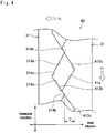
- a structure of the torque cam assembly 40 is illustrated in an enlarged scale in Fig. 4 .
- the first cam face 41a and the second cam face 314a are individually inclined at a predetermined degree in the circumferential direction, and those cam faces are opposed to each other.
- a ridge 413b and a valley 413c are formed alternately on the first cam face 41 a of the first cam shaft 41 as a drive member (i.e., a first cam member), and a ridge 314b and a valley 314c are formed alternately on the second cam face 314a of the piston 31 as a driven member (i.e., a second cam member).
- Each ridge 413b of the first cam face 41a is individually contacted to the ridge 314b of the second cam face 314a in a slidable manner.
- the piston 31 is rotated by a rotation of the first cam shaft 14 through the second cam face 314a and the first cam face 41a thus brought into frictional engagement to each other. Consequently, since the first cam face 41a and the second cam face 314a are inclined with respect to a rotational direction, a component of force acting in the rotational direction acts in the axial direction. That is, a load Fr acting on the contact face between the first cam face 41a and the second cam face 314a in the rotational direction is converted into a thrust force Ft acting in the axial direction.
- the piston 31 is moved toward the movable sheave 14 by a thrust force derived from the thrust force Ft.
- the thrust force Ft is varied depending on a transmission torque, and when the transmission torque of the torque cam assembly 40 is increased to an extent possible to establish the thrust force Ft for moving the piston 31 toward the movable sheave 14, a clearance D in the axial direction between ridge 314b of the piston 31 and valley 413c of the first cam shaft 41 is widened depending on the transmission torque.
- the thrust force Ft also acts to assist a belt clamping pressure of the driven pulley 8. That is, since the first cam shaft 41 is fixed in the axial direction, the first cam shaft 41 serves as a reaction element to move the movable sheave 14 in the axial direction and to establish the belt clamping pressure of the driven pulley 8.
- a surface treatment to increase a friction coefficient may be applied to the cam faces 41a and 314a.
- the output gear 16 is a helical gear
- an inclination ⁇ of the cam face 41a or 314a with respect to the rotational direction may be reduced to be smaller than an inclination of the gear tooth 16a with respect to the axial direction.
- the actuator 15 may be provided with a precompression device for applying an axial thrust to the movable sheave 14 even when none of the hydraulic actuator 30 and torque cam assembly 40 is in activation.
- a coil spring may be arranged in the hydraulic chamber 30 to serve as the precompression device while being contacted to the back face of the movable sheave 14 and an inner wall of the piston 31.
- the precompression device is used to establish an axial thrust to create a belt clamping pressure of the driven pulley 8 at an initial phase where an engine torque has not yet been delivered to the driven pulley 8.
- the vehicle Ve shown in Fig. 1 is an FF (i.e., Front engine Front drive) layout vehicle in which torque of the output gear 16 is delivered to a front differential 18 as a final reduction through the reduction gear 17.
- FF Front engine Front drive
- the diametrically larger gear 17a is fitted onto a reduction gear shaft 17b while being meshed with the output gear 16.
- a diametrically smaller gear 17c is also fitted onto the reduction gear shaft 17b while being meshed with a ring gear 18a of the front differential 18.
- the torque delivered to the front differential 18 is distributed to not shown drive wheels through drive shafts 19.
- the hydraulic circuit 100 is provided with a mechanical oil pump 101 as a hydraulic source.
- the oil pump 101 is driven by the engine 1 to pump up the oil from an oil pan 102 and to discharge the oil to an oil passage 111.
- the oil pump 101 is driven by the engine 1 in both cases in which the engine 1 is driven by burning fuel and in which the engine 1 is rotated passively by an inertial force of the coasting vehicle Ve without fuel supply. That is, the oil pump 101 is driven to generate hydraulic pressure not only during driving the vehicle by the engine 1 but also during applying an engine braking force to the vehicle Ve.
- the vehicle Ve is provided with a not shown electronic control unit (ECU).
- the oil discharged from the oil pump 101 is distributed to the hydraulic chamber 12A of the actuator 12 of the drive pulley 7 to change a speed ratio by changing an effective running diameter of the belt 9, and to the hydraulic chamber 32 of the actuator 15 of the driven pulley 8 to establish a belt clamping pressure by the driven pulley 8.
- relatively highly pressurized oil is delivered to the hydraulic chambers 12A and 32.
- the hydraulic chamber 12A of the drive pulley 7 is connected to an oil passage 112, and an electromagnetic on-off valve DSP1 is disposed on the oil passage 112 to selectively provide a connection between the oil passages 111 and 112. That is, an oil supply to the hydraulic chamber 12A is selectively enabled by electrically switching the on-off valve DSP1 to selectively open a delivery route.
- a discharging passage 114 branches from the oil passage 112 to provide a connection between the hydraulic chamber 12A and an oil pan 102, and an electromagnetic on-off valve DSP2 is disposed on the discharging passage 114. Therefore, the oil can be selectively drained from the hydraulic chamber 12A to the oil pan 102 by electrically switching the on-off valve DSP2 to selectively open a discharging route.
- the hydraulic chamber 32 of the driven pulley 8 is connected to an oil passage 113, and an electromagnetic on-off valve DSS1 is disposed on the oil passage 113 to selectively provide a connection between the oil passages 111 and 113. That is, an oil supply to the hydraulic chamber 32 is selectively enabled by electrically switching the on-off valve DSS1 to selectively open a delivery route.
- a drain passage 115 branches from the oil passage 113 to provide a connection between the hydraulic chamber 32 and the oil pan 102, and an electromagnetic on-off valve DSS2 is disposed on the drain passage 115. Therefore, the oil can be selectively drained from the hydraulic chamber 32 to the oil pan 102 by electrically switching the on-off valve DSS2 to selectively open a discharging route.
- a torque transmitting capacity of the CVT 5 is controlled in such a manner that a belt slippage can be prevented by controlling oil delivered to the hydraulic chamber 32 of the driven pulley 8 establishing a belt clamping pressure.
- a required driving force is calculated based on an opening degree of an accelerator or a throttle valve, and a target engine torque is calculated based on the required driving force.
- a target pressure in the hydraulic chamber 32 is calculated based on a parameter such as an input torque to the CVT 5, and the pressure in the hydraulic chamber 32 is controlled to achieve the target pressure.
- a map or formula for determining the target pressure in the hydraulic chamber 32 based on the above-mentioned parameter is installed in the electronic control unit.
- hydraulic pressure in the hydraulic chamber 32 of the driven pulley 8 is increased.
- hydraulic pressure in the hydraulic chamber 32 can be increased by opening the on-off valve DSS1 to provide a connection between the oil pump 101 and the hydraulic chamber 32, while closing the on-off valve DSS2 to close the drain passage 115.
- hydraulic pressure in the hydraulic chamber 32 of the driven pulley 8 is reduced.
- hydraulic pressure in the hydraulic chamber 32 can be reduced by closing the on-off valve DSS1 to stop oil delivery to the hydraulic chamber 32, while opening the on-off valve DSS2 to allow drainage of oil from the hydraulic chamber 32.
- torque transmitting capacity of the CVT 5 is maintained by confining oil in the hydraulic chamber 32 by closing both on-off valves DSS1 and DSS2.
- a required driving force to propel the vehicle is calculated based on a vehicle speed and a depression of an accelerator pedal (i.e., an opening degree of the accelerator), and a target engine power is calculated based on the required driving force.
- a target speed engine speed to achieve the target engine power is calculated in an optimally fuel efficient manner, and a speed ratio of the CVT 5 is controlled to adjust an actual engine speed to the target engine speed.
- speed ratio of the CVT 5 is changed by changing a delivery amount of the oil to the hydraulic chamber 12A of the drive pulley 7.
- a map or formula for determining the oil delivery amount to the hydraulic chamber 12A based on the target speed ratio of the CVT 5 is installed in the electronic control unit. Then, the oil delivery amount to the hydraulic chamber 12A of the drive pulley 7 is controlled by selectively opening and closing the on-off valves DSP1 and DSP2 in such a manner to achieve the target delivery amount.
- the on-off valve DSP1 is opened to increase a delivery amount of the oil to the hydraulic chamber 12A to narrow the belt groove of the drive pulley 7 (to increase an effective running diameter of the belt 9).
- the on-off valve DSP2 is opened to drain oil from the hydraulic chamber 12A to the oil pan 102 to widen the belt groove of the drive pulley 7 (to decrease an effective running diameter of the belt 9).
- oil is confined in the hydraulic chamber 12A by closing all of the on-off valves DSP1, DSP2, DSS1 and DSS2.
- a speed ratio of the CVT 5 is controlled in such a manner that the engine 1 is operated in line with an optimum fuel efficient curve.
- a speed ratio of the CVT 5 may also be changed stepwise (in both upshifting and downshifting).
- the speed ratio of the CVT 5 is fixed to the ratio selected by the shifting device irrespective of the optimum fuel efficient curve.
- the belt clamping pressure of the driven pulley 8 is kept to a constant level.
- oil is confined in both chambers 12A and 32 by closing all of the on-off valves DSP1, DSP2, DSS1 and DSS2.
- a poppet valve or a check valve adapted to prevent an oil leakage therefrom may by suitable for the on-off valves DSP1, DSP2, DSS1 and DSS2.
- the piston can be actuated to increase the pressure in the hydraulic chamber by a thrust force generated by a relative rotation of the torque cam assembly resulting from increase in a transmission torque of the driven pulley.
- a required belt clamping pressure of the driven pulley may also be ensured by the thrust force generated by the torque cam assembly to prevent an occurrence of belt slippage.
- the torque cam assembly is adapted to generate a thrust force in accordance with a transmission torque of the driven pulley, a required belt clamping pressure of the driven pulley can be achieved promptly.
- a transmission torque required by the driver can be maintained by maintaining the pressure in the hydraulic chamber of the driven pulley to a relatively low level without requiring a complex control.
- a speed ratio of the CVT can be fixed by closing the on-off valves to confine the oil in the hydraulic chamber of the pulley. Therefore, it is not necessary to generate a high pressure by driving the oil pump to regulate the pressure in the hydraulic chamber. For this reason, power loss can be reduced and fuel can be saved.
- the pressure in the hydraulic chamber can be increased to ensure a required belt clamping pressure of the driven pulley by pushing the piston by the torque cam assembly even when the oil cannot be delivered to the driven pulley due to failure of a hydraulic control unit.
- damage on the CVT can be limited.
Claims (5)
- Transmission à variation continue (5) entraînée par courroie, comprenant :une poulie d'entraînement (7) et une poulie entraînée (8), dont chacune est formée par une poulie à gorge fixe (10, 13) intégrée avec arbre rotatif (4, 6) et une poulie à gorge mobile (11, 14) montée sur l'arbre rotatif tout en étant autorisée à effectuer un mouvement de va-et-vient sur ce dernier ; etune courroie (9) s'étendant entre les poulies (7, 8) ;dans laquelle :un piston (31) est monté sur l'arbre rotatif (6) intégré avec la poulie entraînée (8) afin de tourner par rapport à cette dernière par le biais d'un palier (68) tout en étant raccordé à une face arrière de la poulie entraînée (8) d'une manière étanche au liquide ; dans laquelle :caractérisée par :un engrenage de sortie (16) est intégré avec le piston (31) monté sur l'arbre rotatif (6) de la poulie entraînée (8) par le biais dudit palier (68) ;une chambre hydraulique (32) formée entre la face arrière de la poulie entraînée (8) et le piston (31) qui est maintenu dans une condition étanche au liquide ;une seconde face de came (314a) qui est formée sur une extrémité d'attaque du piston (31) dans un côté opposé de la poulie entraînée (8) ;une première face de came (41a) qui est amenée en contact avec la seconde face de came (314a) pour convertir un couple en une force de poussée axiale ;un premier élément de came (41) ayant la première face de came (41a) qui est montée sur l'arbre rotatif de la poulie entraînée (8) afin de tourner de manière solidaire avec ce dernier, et qui est fixée dans la direction axiale.
- Transmission à variation continue (5) entraînée par courroie selon la revendication 1, dans laquelle une face d'extrémité du palier faisant face à la poulie entraînée (7) est située dans une position pour ne pas venir en contact avec le piston (31).
- Transmission à variation continue (5) entraînée par courroie selon la revendication 1 ou 2,
dans laquelle l'engrenage de sortie (16) est situé entre la première face de came et une cloison formant la chambre hydraulique (32) dans la direction axiale, et
dans laquelle le palier (68) est recouvert avec l'engrenage de sortie (16) dans la direction axiale. - Transmission à variation continue (5) entraînée par courroie selon l'une quelconque des revendications 1 à 3,
dans laquelle le premier élément de came (41) est formé selon une forme cylindrique comprenant une partie diamétralement plus grande et une partie diamétralement plus petite dans laquelle son diamètre externe est inférieur à celui de la partie diamétralement plus grande,
dans laquelle la première face de came (41a) est formée sur une face d'extrémité de la partie diamétralement plus grande faisant face à la poulie entraînée (8), et
dans laquelle le palier (68) est disposé entre une face circonférentielle externe de la partie diamétralement plus petite et une face circonférentielle interne du piston (31). - Transmission à variation continue (5) entraînée par courroie selon la revendication 4,
dans laquelle une face circonférentielle interne du premier élément de came (41) est montée sur une face circonférentielle externe de l'arbre rotatif (6) de la poulie entraînée (8) par le biais d'une cannelure, et
dans laquelle la cannelure, l'engrenage de sortie (16) et le palier (68) sont recouverts dans la direction axiale.
Applications Claiming Priority (1)
| Application Number | Priority Date | Filing Date | Title |
|---|---|---|---|
| PCT/JP2013/065885 WO2014196084A1 (fr) | 2013-06-07 | 2013-06-07 | Transmission continue de type à courroie |
Publications (3)
| Publication Number | Publication Date |
|---|---|
| EP3006777A1 EP3006777A1 (fr) | 2016-04-13 |
| EP3006777A4 EP3006777A4 (fr) | 2016-05-25 |
| EP3006777B1 true EP3006777B1 (fr) | 2017-08-02 |
Family
ID=52007755
Family Applications (1)
| Application Number | Title | Priority Date | Filing Date |
|---|---|---|---|
| EP13886368.3A Not-in-force EP3006777B1 (fr) | 2013-06-07 | 2013-06-07 | Transmission continue de type à courroie |
Country Status (5)
| Country | Link |
|---|---|
| US (1) | US9777810B2 (fr) |
| EP (1) | EP3006777B1 (fr) |
| JP (1) | JP6020720B2 (fr) |
| CN (1) | CN105264268B (fr) |
| WO (1) | WO2014196084A1 (fr) |
Families Citing this family (10)
| Publication number | Priority date | Publication date | Assignee | Title |
|---|---|---|---|---|
| WO2017213190A1 (fr) * | 2016-06-07 | 2017-12-14 | アイシン・エィ・ダブリュ株式会社 | Boîte de vitesses |
| US10267391B2 (en) * | 2016-06-16 | 2019-04-23 | GM Global Technology Operations LLC | Continuously variable transmission with wedge actuation mechanism |
| US10941840B2 (en) | 2016-06-16 | 2021-03-09 | GM Global Technology Operations LLC | Continuously variable transmission with wedge actuation mechanism |
| JP2018003952A (ja) * | 2016-07-01 | 2018-01-11 | 本田技研工業株式会社 | ベルト式無段変速機 |
| MX2019005798A (es) * | 2016-11-24 | 2019-08-12 | Nissan Motor | Metodo para controlar transmision continuamente variable y sistema de transmision continuamente variable. |
| US10473200B2 (en) | 2017-12-01 | 2019-11-12 | GM Global Technology Operations LLC | Continuously variable transmission with wedge actuation mechanism |
| US10473213B2 (en) * | 2017-12-01 | 2019-11-12 | GM Global Technology Operations LLC | Method of controlling clamping of wedge-actuated CVT and powertrain with wedge-actuated CVT |
| CN112639329A (zh) * | 2018-10-22 | 2021-04-09 | 加特可株式会社 | 无级变速器 |
| JP7339909B2 (ja) * | 2020-03-23 | 2023-09-06 | 本田技研工業株式会社 | 従動プーリ装置 |
| CN112728029B (zh) * | 2020-12-29 | 2023-03-17 | 哈尔滨剑桥学院 | 一种cvt变速器传动机构 |
Family Cites Families (36)
| Publication number | Priority date | Publication date | Assignee | Title |
|---|---|---|---|---|
| DE1178664B (de) * | 1962-07-31 | 1964-09-24 | Reimers Getriebe K G | Stufenlos verstellbares Kegelscheibengetriebe mit auf den Getriebewellen axial verschiebbaren Kegelscheiben |
| DE3538884A1 (de) * | 1985-11-02 | 1987-05-21 | Ford Werke Ag | Stufenlos regelbares getriebeaggregat fuer kraftfahrzeuge |
| US4838834A (en) * | 1988-03-29 | 1989-06-13 | Bando Chemical Industries, Ltd. | Speed-shifting device |
| DE4036683B4 (de) * | 1989-11-21 | 2008-05-29 | Luk Lamellen Und Kupplungsbau Beteiligungs Kg | Stufenlos einstellbares Kegelscheibenumschlingungsgetriebe |
| US5184981A (en) * | 1991-01-07 | 1993-02-09 | Wittke Ernest C | Cam loaded continuously variable transmission |
| DE4234294B4 (de) | 1991-10-19 | 2008-04-03 | Luk Lamellen Und Kupplungsbau Beteiligungs Kg | Kegelscheibenumschlingungsgetriebe |
| JP3961039B2 (ja) * | 1994-12-06 | 2007-08-15 | ルーク ゲトリーベ−ジステーメ ゲゼルシャフト ミット ベシュレンクテル ハフツング | トルクセンサ及び円錐形プーリー巻掛け式伝動装置 |
| KR100583853B1 (ko) * | 1997-11-07 | 2006-05-26 | 루크 라멜렌 운트 쿠플룽스바우 베타일리궁스 카게 | 원추형 풀리 및 벨트를 포함한 무단변속기 |
| GB2331561B (en) * | 1997-11-24 | 2002-09-18 | Luk Getriebe Systeme Gmbh | Continuously variable speed transmission |
| DE19909347B4 (de) * | 1998-03-10 | 2012-03-29 | Schaeffler Technologies Gmbh & Co. Kg | Getriebe |
| DE19921750B4 (de) * | 1998-05-18 | 2012-03-08 | Schaeffler Technologies Gmbh & Co. Kg | Getriebe |
| JP3116035B2 (ja) | 1998-07-03 | 2000-12-11 | 富士重工業株式会社 | ベルト式無段変速機のプーリ装置 |
| JP2000161454A (ja) * | 1998-11-18 | 2000-06-16 | Luk Getriebe Syst Gmbh | 伝動装置 |
| DE19958073B4 (de) * | 1998-12-16 | 2012-04-26 | Schaeffler Technologies Gmbh & Co. Kg | Kegelscheibenumschlingungsgetriebe |
| JP2000240768A (ja) * | 1999-02-24 | 2000-09-05 | Luk Lamellen & Kupplungsbau Gmbh | 伝動装置 |
| DE10139121A1 (de) * | 2000-09-08 | 2002-03-21 | Luk Lamellen & Kupplungsbau | Anpreßsystem |
| JP4848559B2 (ja) * | 2000-12-20 | 2011-12-28 | シェフラー テクノロジーズ ゲゼルシャフト ミット ベシュレンクテル ハフツング ウント コンパニー コマンディートゲゼルシャフト | 組み込まれたトルク感応器を備えた無段変速可能な円錐形プーリ巻掛け伝動装置 |
| DE20380252U1 (de) * | 2002-09-05 | 2005-03-24 | Luk Lamellen & Kupplungsbau | Kegelscheibenumschlingungsgetriebe |
| JP2005315301A (ja) * | 2004-04-27 | 2005-11-10 | Toyota Motor Corp | ベルト式無段変速機 |
| JP4151607B2 (ja) * | 2004-05-06 | 2008-09-17 | トヨタ自動車株式会社 | ベルト式無段変速機 |
| US7686715B2 (en) * | 2004-07-08 | 2010-03-30 | Gm Global Technology Operations, Inc. | Hybrid clamping mechanism for belt continuously variable transmission and method of use thereof |
| EP1781969B1 (fr) * | 2004-08-19 | 2008-10-01 | LuK Lamellen und Kupplungsbau Beteiligungs KG | Transmission a variation continue a disques coniques, procede de fabrication de ladite transmission et vehicule equipe de cette transmission |
| US20060058130A1 (en) * | 2004-08-24 | 2006-03-16 | Luk Lamellen Und Kupplungsbau Beteiligungs Kg | Belt-driven conical-pulley transmission, method for producing it, and motor vehicle having such a transmission |
| ATE406535T1 (de) * | 2004-10-23 | 2008-09-15 | Luk Lamellen & Kupplungsbau | Kegelscheibenumschlingungsgetriebe, sowie fahrzeug mit einem derartigem getriebe |
| US7967707B2 (en) * | 2005-12-17 | 2011-06-28 | Luk Lamellen Und Kupplungsbau Beteiligungs Kg | Belt-driven conical-pulley transmission with improved towing suitability |
| US20070197322A1 (en) * | 2005-12-21 | 2007-08-23 | Luk Lamellen Und Kupplungsbau Beteiligungs Kg | Method for improving the towing suitability of a motor vehicle equipped with a belt-driven conical-pulley transmission, and a conical disk pair |
| JP2007232147A (ja) * | 2006-03-02 | 2007-09-13 | Yamaha Motor Co Ltd | 車両 |
| CN101500875A (zh) * | 2006-08-09 | 2009-08-05 | 卢克摩擦片和离合器两合公司 | 用于限制具有组合的液压机械的转矩探测装置的锥盘缠绕接触装置变速器的输入力矩的方法和装置 |
| WO2008101465A1 (fr) * | 2007-02-23 | 2008-08-28 | Luk Lamellen Und Kupplungsbau Beteiligungs Kg | Transmission à variation continue à poulies coniques avec système hydraulique et source auxiliaire d'huile |
| JP2009002414A (ja) * | 2007-06-20 | 2009-01-08 | Toyota Motor Corp | トルクカム装置およびベルト式無段変速機 |
| DE102008057114A1 (de) * | 2007-11-23 | 2009-05-28 | Luk Lamellen Und Kupplungsbau Beteiligungs Kg | Kegelscheibenpaar mit integriertem Drehmomentfühler für ein Kegelscheibenumschlingungsgetriebe |
| DE102008059807A1 (de) * | 2007-12-19 | 2009-06-25 | Luk Lamellen Und Kupplungsbau Beteiligungs Kg | Hydrauliksystem |
| JP4463858B2 (ja) * | 2008-01-11 | 2010-05-19 | 株式会社山田製作所 | Vベルト式自動変速装置の従動側プーリ |
| JP2009191923A (ja) * | 2008-02-13 | 2009-08-27 | Toyota Motor Corp | ベルト式無段変速機 |
| JP2009192018A (ja) | 2008-02-15 | 2009-08-27 | Toyota Motor Corp | 無段変速機 |
| JP5692358B2 (ja) | 2011-03-23 | 2015-04-01 | トヨタ自動車株式会社 | ベルト式無段変速機 |
-
2013
- 2013-06-07 CN CN201380077191.5A patent/CN105264268B/zh not_active Expired - Fee Related
- 2013-06-07 EP EP13886368.3A patent/EP3006777B1/fr not_active Not-in-force
- 2013-06-07 WO PCT/JP2013/065885 patent/WO2014196084A1/fr active Application Filing
- 2013-06-07 US US14/896,049 patent/US9777810B2/en active Active
- 2013-06-07 JP JP2015521257A patent/JP6020720B2/ja active Active
Non-Patent Citations (1)
| Title |
|---|
| None * |
Also Published As
| Publication number | Publication date |
|---|---|
| JPWO2014196084A1 (ja) | 2017-02-23 |
| EP3006777A1 (fr) | 2016-04-13 |
| EP3006777A4 (fr) | 2016-05-25 |
| US9777810B2 (en) | 2017-10-03 |
| CN105264268A (zh) | 2016-01-20 |
| WO2014196084A1 (fr) | 2014-12-11 |
| JP6020720B2 (ja) | 2016-11-02 |
| CN105264268B (zh) | 2017-10-20 |
| US20160131230A1 (en) | 2016-05-12 |
Similar Documents
| Publication | Publication Date | Title |
|---|---|---|
| EP3006777B1 (fr) | Transmission continue de type à courroie | |
| US8092325B2 (en) | Continuously variable belt transmission for a vehicle | |
| US8562463B2 (en) | Belt type continuously variable transmission | |
| US9616739B2 (en) | Power transmission apparatus for hybrid electric vehicle | |
| US20070191178A1 (en) | Power transmission system | |
| US7789779B2 (en) | Continuously variable transmission | |
| KR20120026961A (ko) | 자동 변속기 및 유압 제어 장치 | |
| US10295056B2 (en) | Mode transition control in a CVT with fixed gear functionality | |
| EP3927999A1 (fr) | Agencement de chaîne cinématique avec transmission à variation continue | |
| US9556931B2 (en) | Element for metallic belt | |
| JP2014114828A (ja) | 油圧制御装置 | |
| US20100099525A1 (en) | Power transmission device and vehicle in which power transmission device is installed | |
| US10941840B2 (en) | Continuously variable transmission with wedge actuation mechanism | |
| US20160047457A1 (en) | Shaft supporting structure of belt-driven continuously variable transmission | |
| CN109210188B (zh) | 无级变速器泵限制停车控制 | |
| JP2009275718A (ja) | 無段変速機 | |
| JP2010071453A (ja) | ベルト式無段変速機のプーリ及びベルト式無段変速機 | |
| JP4462164B2 (ja) | 油圧制御装置 | |
| JP3675329B2 (ja) | ベルト式無段変速装置 | |
| US10001199B2 (en) | Continuously variable transmission and method for controlling the same | |
| JP2010060102A (ja) | ベルト式無段変速機のプーリ及びベルト式無段変速機 | |
| JP2007285333A (ja) | 車両用ベルト式無段変速機の制御装置 | |
| US10054221B2 (en) | Hydraulic control device of belt-type continuously variable transmission | |
| JP2020016297A (ja) | 動力伝達装置およびその制御方法 | |
| JP2019065994A (ja) | 無段変速機の制御装置 |
Legal Events
| Date | Code | Title | Description |
|---|---|---|---|
| PUAI | Public reference made under article 153(3) epc to a published international application that has entered the european phase |
Free format text: ORIGINAL CODE: 0009012 |
|
| 17P | Request for examination filed |
Effective date: 20151207 |
|
| AK | Designated contracting states |
Kind code of ref document: A1 Designated state(s): AL AT BE BG CH CY CZ DE DK EE ES FI FR GB GR HR HU IE IS IT LI LT LU LV MC MK MT NL NO PL PT RO RS SE SI SK SM TR |
|
| AX | Request for extension of the european patent |
Extension state: BA ME |
|
| A4 | Supplementary search report drawn up and despatched |
Effective date: 20160428 |
|
| RIC1 | Information provided on ipc code assigned before grant |
Ipc: F16H 9/18 20060101AFI20160421BHEP |
|
| DAX | Request for extension of the european patent (deleted) | ||
| GRAP | Despatch of communication of intention to grant a patent |
Free format text: ORIGINAL CODE: EPIDOSNIGR1 |
|
| STAA | Information on the status of an ep patent application or granted ep patent |
Free format text: STATUS: GRANT OF PATENT IS INTENDED |
|
| INTG | Intention to grant announced |
Effective date: 20170224 |
|
| RIN1 | Information on inventor provided before grant (corrected) |
Inventor name: KAWAKAMI, TAKAHO Inventor name: YANAGIDA, TOMOAKI |
|
| GRAS | Grant fee paid |
Free format text: ORIGINAL CODE: EPIDOSNIGR3 |
|
| GRAA | (expected) grant |
Free format text: ORIGINAL CODE: 0009210 |
|
| STAA | Information on the status of an ep patent application or granted ep patent |
Free format text: STATUS: THE PATENT HAS BEEN GRANTED |
|
| AK | Designated contracting states |
Kind code of ref document: B1 Designated state(s): AL AT BE BG CH CY CZ DE DK EE ES FI FR GB GR HR HU IE IS IT LI LT LU LV MC MK MT NL NO PL PT RO RS SE SI SK SM TR |
|
| REG | Reference to a national code |
Ref country code: CH Ref legal event code: EP Ref country code: AT Ref legal event code: REF Ref document number: 914838 Country of ref document: AT Kind code of ref document: T Effective date: 20170815 |
|
| REG | Reference to a national code |
Ref country code: IE Ref legal event code: FG4D |
|
| REG | Reference to a national code |
Ref country code: DE Ref legal event code: R096 Ref document number: 602013024610 Country of ref document: DE |
|
| REG | Reference to a national code |
Ref country code: NL Ref legal event code: MP Effective date: 20170802 |
|
| REG | Reference to a national code |
Ref country code: AT Ref legal event code: MK05 Ref document number: 914838 Country of ref document: AT Kind code of ref document: T Effective date: 20170802 |
|
| REG | Reference to a national code |
Ref country code: LT Ref legal event code: MG4D |
|
| PG25 | Lapsed in a contracting state [announced via postgrant information from national office to epo] |
Ref country code: NL Free format text: LAPSE BECAUSE OF FAILURE TO SUBMIT A TRANSLATION OF THE DESCRIPTION OR TO PAY THE FEE WITHIN THE PRESCRIBED TIME-LIMIT Effective date: 20170802 Ref country code: AT Free format text: LAPSE BECAUSE OF FAILURE TO SUBMIT A TRANSLATION OF THE DESCRIPTION OR TO PAY THE FEE WITHIN THE PRESCRIBED TIME-LIMIT Effective date: 20170802 Ref country code: SE Free format text: LAPSE BECAUSE OF FAILURE TO SUBMIT A TRANSLATION OF THE DESCRIPTION OR TO PAY THE FEE WITHIN THE PRESCRIBED TIME-LIMIT Effective date: 20170802 Ref country code: HR Free format text: LAPSE BECAUSE OF FAILURE TO SUBMIT A TRANSLATION OF THE DESCRIPTION OR TO PAY THE FEE WITHIN THE PRESCRIBED TIME-LIMIT Effective date: 20170802 Ref country code: FI Free format text: LAPSE BECAUSE OF FAILURE TO SUBMIT A TRANSLATION OF THE DESCRIPTION OR TO PAY THE FEE WITHIN THE PRESCRIBED TIME-LIMIT Effective date: 20170802 Ref country code: NO Free format text: LAPSE BECAUSE OF FAILURE TO SUBMIT A TRANSLATION OF THE DESCRIPTION OR TO PAY THE FEE WITHIN THE PRESCRIBED TIME-LIMIT Effective date: 20171102 Ref country code: LT Free format text: LAPSE BECAUSE OF FAILURE TO SUBMIT A TRANSLATION OF THE DESCRIPTION OR TO PAY THE FEE WITHIN THE PRESCRIBED TIME-LIMIT Effective date: 20170802 |
|
| PG25 | Lapsed in a contracting state [announced via postgrant information from national office to epo] |
Ref country code: BG Free format text: LAPSE BECAUSE OF FAILURE TO SUBMIT A TRANSLATION OF THE DESCRIPTION OR TO PAY THE FEE WITHIN THE PRESCRIBED TIME-LIMIT Effective date: 20171102 Ref country code: LV Free format text: LAPSE BECAUSE OF FAILURE TO SUBMIT A TRANSLATION OF THE DESCRIPTION OR TO PAY THE FEE WITHIN THE PRESCRIBED TIME-LIMIT Effective date: 20170802 Ref country code: ES Free format text: LAPSE BECAUSE OF FAILURE TO SUBMIT A TRANSLATION OF THE DESCRIPTION OR TO PAY THE FEE WITHIN THE PRESCRIBED TIME-LIMIT Effective date: 20170802 Ref country code: IS Free format text: LAPSE BECAUSE OF FAILURE TO SUBMIT A TRANSLATION OF THE DESCRIPTION OR TO PAY THE FEE WITHIN THE PRESCRIBED TIME-LIMIT Effective date: 20171202 Ref country code: GR Free format text: LAPSE BECAUSE OF FAILURE TO SUBMIT A TRANSLATION OF THE DESCRIPTION OR TO PAY THE FEE WITHIN THE PRESCRIBED TIME-LIMIT Effective date: 20171103 Ref country code: RS Free format text: LAPSE BECAUSE OF FAILURE TO SUBMIT A TRANSLATION OF THE DESCRIPTION OR TO PAY THE FEE WITHIN THE PRESCRIBED TIME-LIMIT Effective date: 20170802 Ref country code: PL Free format text: LAPSE BECAUSE OF FAILURE TO SUBMIT A TRANSLATION OF THE DESCRIPTION OR TO PAY THE FEE WITHIN THE PRESCRIBED TIME-LIMIT Effective date: 20170802 |
|
| REG | Reference to a national code |
Ref country code: DE Ref legal event code: R084 Ref document number: 602013024610 Country of ref document: DE |
|
| REG | Reference to a national code |
Ref country code: GB Ref legal event code: 746 Effective date: 20180320 |
|
| PG25 | Lapsed in a contracting state [announced via postgrant information from national office to epo] |
Ref country code: CZ Free format text: LAPSE BECAUSE OF FAILURE TO SUBMIT A TRANSLATION OF THE DESCRIPTION OR TO PAY THE FEE WITHIN THE PRESCRIBED TIME-LIMIT Effective date: 20170802 Ref country code: RO Free format text: LAPSE BECAUSE OF FAILURE TO SUBMIT A TRANSLATION OF THE DESCRIPTION OR TO PAY THE FEE WITHIN THE PRESCRIBED TIME-LIMIT Effective date: 20170802 Ref country code: DK Free format text: LAPSE BECAUSE OF FAILURE TO SUBMIT A TRANSLATION OF THE DESCRIPTION OR TO PAY THE FEE WITHIN THE PRESCRIBED TIME-LIMIT Effective date: 20170802 |
|
| REG | Reference to a national code |
Ref country code: DE Ref legal event code: R097 Ref document number: 602013024610 Country of ref document: DE |
|
| REG | Reference to a national code |
Ref country code: FR Ref legal event code: PLFP Year of fee payment: 6 |
|
| PG25 | Lapsed in a contracting state [announced via postgrant information from national office to epo] |
Ref country code: SM Free format text: LAPSE BECAUSE OF FAILURE TO SUBMIT A TRANSLATION OF THE DESCRIPTION OR TO PAY THE FEE WITHIN THE PRESCRIBED TIME-LIMIT Effective date: 20170802 Ref country code: SK Free format text: LAPSE BECAUSE OF FAILURE TO SUBMIT A TRANSLATION OF THE DESCRIPTION OR TO PAY THE FEE WITHIN THE PRESCRIBED TIME-LIMIT Effective date: 20170802 Ref country code: IT Free format text: LAPSE BECAUSE OF FAILURE TO SUBMIT A TRANSLATION OF THE DESCRIPTION OR TO PAY THE FEE WITHIN THE PRESCRIBED TIME-LIMIT Effective date: 20170802 Ref country code: EE Free format text: LAPSE BECAUSE OF FAILURE TO SUBMIT A TRANSLATION OF THE DESCRIPTION OR TO PAY THE FEE WITHIN THE PRESCRIBED TIME-LIMIT Effective date: 20170802 |
|
| PLBE | No opposition filed within time limit |
Free format text: ORIGINAL CODE: 0009261 |
|
| STAA | Information on the status of an ep patent application or granted ep patent |
Free format text: STATUS: NO OPPOSITION FILED WITHIN TIME LIMIT |
|
| 26N | No opposition filed |
Effective date: 20180503 |
|
| PG25 | Lapsed in a contracting state [announced via postgrant information from national office to epo] |
Ref country code: SI Free format text: LAPSE BECAUSE OF FAILURE TO SUBMIT A TRANSLATION OF THE DESCRIPTION OR TO PAY THE FEE WITHIN THE PRESCRIBED TIME-LIMIT Effective date: 20170802 |
|
| REG | Reference to a national code |
Ref country code: CH Ref legal event code: PL |
|
| REG | Reference to a national code |
Ref country code: BE Ref legal event code: MM Effective date: 20180630 |
|
| REG | Reference to a national code |
Ref country code: IE Ref legal event code: MM4A |
|
| PG25 | Lapsed in a contracting state [announced via postgrant information from national office to epo] |
Ref country code: MC Free format text: LAPSE BECAUSE OF FAILURE TO SUBMIT A TRANSLATION OF THE DESCRIPTION OR TO PAY THE FEE WITHIN THE PRESCRIBED TIME-LIMIT Effective date: 20170802 Ref country code: LU Free format text: LAPSE BECAUSE OF NON-PAYMENT OF DUE FEES Effective date: 20180607 |
|
| PG25 | Lapsed in a contracting state [announced via postgrant information from national office to epo] |
Ref country code: IE Free format text: LAPSE BECAUSE OF NON-PAYMENT OF DUE FEES Effective date: 20180607 Ref country code: CH Free format text: LAPSE BECAUSE OF NON-PAYMENT OF DUE FEES Effective date: 20180630 Ref country code: LI Free format text: LAPSE BECAUSE OF NON-PAYMENT OF DUE FEES Effective date: 20180630 |
|
| PG25 | Lapsed in a contracting state [announced via postgrant information from national office to epo] |
Ref country code: BE Free format text: LAPSE BECAUSE OF NON-PAYMENT OF DUE FEES Effective date: 20180630 |
|
| PG25 | Lapsed in a contracting state [announced via postgrant information from national office to epo] |
Ref country code: MT Free format text: LAPSE BECAUSE OF NON-PAYMENT OF DUE FEES Effective date: 20180607 |
|
| PG25 | Lapsed in a contracting state [announced via postgrant information from national office to epo] |
Ref country code: TR Free format text: LAPSE BECAUSE OF FAILURE TO SUBMIT A TRANSLATION OF THE DESCRIPTION OR TO PAY THE FEE WITHIN THE PRESCRIBED TIME-LIMIT Effective date: 20170802 |
|
| PG25 | Lapsed in a contracting state [announced via postgrant information from national office to epo] |
Ref country code: PT Free format text: LAPSE BECAUSE OF FAILURE TO SUBMIT A TRANSLATION OF THE DESCRIPTION OR TO PAY THE FEE WITHIN THE PRESCRIBED TIME-LIMIT Effective date: 20170802 |
|
| PG25 | Lapsed in a contracting state [announced via postgrant information from national office to epo] |
Ref country code: HU Free format text: LAPSE BECAUSE OF FAILURE TO SUBMIT A TRANSLATION OF THE DESCRIPTION OR TO PAY THE FEE WITHIN THE PRESCRIBED TIME-LIMIT; INVALID AB INITIO Effective date: 20130607 Ref country code: MK Free format text: LAPSE BECAUSE OF NON-PAYMENT OF DUE FEES Effective date: 20170802 Ref country code: CY Free format text: LAPSE BECAUSE OF FAILURE TO SUBMIT A TRANSLATION OF THE DESCRIPTION OR TO PAY THE FEE WITHIN THE PRESCRIBED TIME-LIMIT Effective date: 20170802 |
|
| PG25 | Lapsed in a contracting state [announced via postgrant information from national office to epo] |
Ref country code: AL Free format text: LAPSE BECAUSE OF FAILURE TO SUBMIT A TRANSLATION OF THE DESCRIPTION OR TO PAY THE FEE WITHIN THE PRESCRIBED TIME-LIMIT Effective date: 20170802 |
|
| PGFP | Annual fee paid to national office [announced via postgrant information from national office to epo] |
Ref country code: FR Payment date: 20210513 Year of fee payment: 9 Ref country code: DE Payment date: 20210511 Year of fee payment: 9 |
|
| PGFP | Annual fee paid to national office [announced via postgrant information from national office to epo] |
Ref country code: GB Payment date: 20210512 Year of fee payment: 9 |
|
| REG | Reference to a national code |
Ref country code: DE Ref legal event code: R119 Ref document number: 602013024610 Country of ref document: DE |
|
| GBPC | Gb: european patent ceased through non-payment of renewal fee |
Effective date: 20220607 |
|
| PG25 | Lapsed in a contracting state [announced via postgrant information from national office to epo] |
Ref country code: FR Free format text: LAPSE BECAUSE OF NON-PAYMENT OF DUE FEES Effective date: 20220630 |
|
| PG25 | Lapsed in a contracting state [announced via postgrant information from national office to epo] |
Ref country code: GB Free format text: LAPSE BECAUSE OF NON-PAYMENT OF DUE FEES Effective date: 20220607 Ref country code: DE Free format text: LAPSE BECAUSE OF NON-PAYMENT OF DUE FEES Effective date: 20230103 |