EP3006126B1 - Tandem rolling mill comprising a control device and control method - Google Patents
Tandem rolling mill comprising a control device and control method Download PDFInfo
- Publication number
- EP3006126B1 EP3006126B1 EP15188340.2A EP15188340A EP3006126B1 EP 3006126 B1 EP3006126 B1 EP 3006126B1 EP 15188340 A EP15188340 A EP 15188340A EP 3006126 B1 EP3006126 B1 EP 3006126B1
- Authority
- EP
- European Patent Office
- Prior art keywords
- roll force
- roll
- strip
- rolling
- rolling stands
- Prior art date
- Legal status (The legal status is an assumption and is not a legal conclusion. Google has not performed a legal analysis and makes no representation as to the accuracy of the status listed.)
- Active
Links
- 238000005096 rolling process Methods 0.000 title claims description 374
- 238000000034 method Methods 0.000 title claims description 15
- 238000004364 calculation method Methods 0.000 claims description 124
- 229910000831 Steel Inorganic materials 0.000 claims description 48
- 239000010959 steel Substances 0.000 claims description 48
- 238000012384 transportation and delivery Methods 0.000 claims description 38
- 238000011144 upstream manufacturing Methods 0.000 claims description 9
- 230000001133 acceleration Effects 0.000 description 8
- 230000008859 change Effects 0.000 description 8
- 230000006870 function Effects 0.000 description 7
- NAWXUBYGYWOOIX-SFHVURJKSA-N (2s)-2-[[4-[2-(2,4-diaminoquinazolin-6-yl)ethyl]benzoyl]amino]-4-methylidenepentanedioic acid Chemical compound C1=CC2=NC(N)=NC(N)=C2C=C1CCC1=CC=C(C(=O)N[C@@H](CC(=C)C(O)=O)C(O)=O)C=C1 NAWXUBYGYWOOIX-SFHVURJKSA-N 0.000 description 4
- 239000000463 material Substances 0.000 description 3
- XEEYBQQBJWHFJM-UHFFFAOYSA-N Iron Chemical compound [Fe] XEEYBQQBJWHFJM-UHFFFAOYSA-N 0.000 description 2
- 230000000694 effects Effects 0.000 description 2
- 238000012821 model calculation Methods 0.000 description 2
- 238000000926 separation method Methods 0.000 description 2
- FZEIVUHEODGHML-UHFFFAOYSA-N 2-phenyl-3,6-dimethylmorpholine Chemical compound O1C(C)CNC(C)C1C1=CC=CC=C1 FZEIVUHEODGHML-UHFFFAOYSA-N 0.000 description 1
- 230000006399 behavior Effects 0.000 description 1
- 230000033228 biological regulation Effects 0.000 description 1
- 238000005097 cold rolling Methods 0.000 description 1
- 238000007599 discharging Methods 0.000 description 1
- 238000005516 engineering process Methods 0.000 description 1
- 230000020169 heat generation Effects 0.000 description 1
- 238000005098 hot rolling Methods 0.000 description 1
- 230000006872 improvement Effects 0.000 description 1
- 238000007689 inspection Methods 0.000 description 1
- 238000009434 installation Methods 0.000 description 1
- 229910052742 iron Inorganic materials 0.000 description 1
- 238000012986 modification Methods 0.000 description 1
- 230000004048 modification Effects 0.000 description 1
- 230000008569 process Effects 0.000 description 1
- 230000005855 radiation Effects 0.000 description 1
- 230000009467 reduction Effects 0.000 description 1
- 239000004065 semiconductor Substances 0.000 description 1
- 230000001629 suppression Effects 0.000 description 1
Images


Classifications
-
- B—PERFORMING OPERATIONS; TRANSPORTING
- B21—MECHANICAL METAL-WORKING WITHOUT ESSENTIALLY REMOVING MATERIAL; PUNCHING METAL
- B21B—ROLLING OF METAL
- B21B37/00—Control devices or methods specially adapted for metal-rolling mills or the work produced thereby
- B21B37/58—Roll-force control; Roll-gap control
-
- B—PERFORMING OPERATIONS; TRANSPORTING
- B21—MECHANICAL METAL-WORKING WITHOUT ESSENTIALLY REMOVING MATERIAL; PUNCHING METAL
- B21B—ROLLING OF METAL
- B21B2271/00—Mill stand parameters
- B21B2271/02—Roll gap, screw-down position, draft position
-
- B—PERFORMING OPERATIONS; TRANSPORTING
- B21—MECHANICAL METAL-WORKING WITHOUT ESSENTIALLY REMOVING MATERIAL; PUNCHING METAL
- B21B—ROLLING OF METAL
- B21B2275/00—Mill drive parameters
- B21B2275/02—Speed
- B21B2275/04—Roll speed
Definitions
- the present invention relates to a control device of a tandem rolling mill and a control method which are suitable for qualitative improvement of a strip.
- a tandem rolling mill according to the preamble of claim 1 and a control method of a tandem rolling mill according to the preamble of claim 7 are known from document JP- A 2009113101 .
- a method in hot strip tandem rolling mill control of a strip, comprises, prior to rolling, predicting a rolling condition of a strip to be rolled, determining a screw-down position (corresponding to a clearance between upper and lower work rolls) and a roll speed, controlling a head end of strip, and thereafter gradually compensating the screw-down position and the roll speed to suitable values by utilizing a strip thickness and a strip tension between rolling stands, which are obtained from a detector.
- Patent Literature 1 Japanese Patent Application Laid-Open No. Hei. 10-263640
- a rolling control method comprises determining a learning coefficient on the basis of a roll force actual value Pact and a roll force prediction model calculated-value Pcal found by substituting the roll force actual value for a roll force prediction model P, separating the learning coefficient into a first learning coefficient Zpk of a component to learn an error intrinsic to a material to be rolled and a second learning coefficient Zpm of a component to learn an error due to the time variance of a rolling machine, and learning the both components separately.
- Patent Literature 2 Japanese Patent Application Laid-Open No. 2013-226596
- a roll force prediction model in which, in addition to processing to learn an estimated error of deformation resistance of a material, to be rolled, on the basis of rolling results, processing to learn an estimation error of a friction coefficient is performed on the basis of rolling results in connection with a friction phenomenon between rolling rolls and the material to be rolled, whereby prediction accuracy of the deformation resistance and friction coefficient is improved and prediction accuracy of the roll force is enhanced.
- Patent Literature 3 Japanese Patent Application Laid-Open No. 2009-113101 ) in which taking notice of a relationship among roll forces of a plurality of rolling stands, prediction accuracy of the roll forces are raised.
- Patent Literature 3 a rolling control method is disclosed in which using errors of the roll forces in the respective rolling stands which are calculated on the basis of roll force actual values in the respective rolling stands and a roll force prediction model calculation value found by substituting a rolling condition actual value, change of errors between an upstream rolling stand and a downstream rolling stand are modeled and, further, variations in roll force prediction errors among the rolling stands are suppressed using the model.
- the roll force prediction model disclosed in Patent Literature 1 is estimated by separating the estimation error of the roll force (a difference between the roll force actual value Pact and the roll force prediction model calculation value Pcal) into an inherent error component of a strip to be rolled (an error predicted using the first learning coefficient Zpk) and an error component due to time variance of a rolling mill (an error predicted using the second learning coefficient Zpm).
- the separation of the error factor is impossible from the first.
- Patent Literature 1 it describes that the separation of the error factor is possible since inclination of the time variance of the rolling mill is small.
- the estimation value of the roll force does not considerably vary. Therefore, there was a case where the inherent error of the strip to be rolled which had been generated was mistakenly separated as the error due to time variance of the rolling mill. Therefore, a problem occurs in which the first learning coefficient Zpk and the second learning coefficient Zpm in the roll force prediction model are improperly learned and the prediction accuracy of the roll force is deteriorated.
- Patent Literature 2 it is actually impossible to discriminate whether, for example, increase of the roll force depends upon increase of the deformation resistance or increase of friction. Therefore, similarly to the case of Patent Literature 1, a problem occurs in which the deformation resistance and the friction coefficient which are used in the roll force prediction model are improperly learned and the prediction accuracy of the roll force is deteriorated.
- the characteristics of the roll force prediction models disclosed in Patent Literature 1 and 2 reside in that learning to be utilized for the prediction is independently performed in the respective rolling stands, on the basis of roll force results obtained in the respective rolling stands. Therefore, there is a case where a learning value in a specific rolling-stand becomes large and, by its reaction, the learning coefficients in neighboring rolling stands become small, and the both are considerably different in learning values. As a result, the roll forces in the respective rolling stands are compensated at large values or small values, so that a problem occurs in which roll force balance specially between the neighboring rolling stands collapses. If the roll force balance between the neighboring rolling stands collapses, a problem occurs in which increase and reduction in strip tensions among the rolling stand become unbalanced and rolling becomes unstable.
- the roll force error change model is configured based on the errors of the roll forces in the respective rolling stands and the learning values in the respective rolling stands are calculated in accordance with the model.
- a learning value in a certain rolling stand is not considerably different from that in another rolling stand, so that roll force balance among the respective rolling stands can be maintained.
- the processing to configure the roll force error change model is required, so that there is a problem in which computational complexity is increased.
- the characteristics of the roll force prediction error complexly varies as the strip is advanced from an upstream rolling stand side to a downstream rolling stand.
- the result roll force is large in the upstream and downstream rolling stands, and the prediction roll force is large in a middle rolling-stand. That is, there is a case where the prediction error leans on the upstream and downstream rolling stands, for example, to a plus side, and to a minus side at a middle portion.
- the present invention has been made in order to solve the problems of the above-mentioned prior art, and the object of the present invention is to provide a control device of a tandem rolling mill and a control device which make it possible to realize balance consistency among a plurality of rolling stands with simple processing.
- a tandem rolling mill for continuously rolling a strip with a plurality of rolling stands, the tandem rolling mill comprising a control device, which comprises a roll force prediction error calculation section estimating roll forces in the respective rolling stands, utilizing rolling actual values acquired in the respective rolling stands when the strip is rolled, and calculating roll force prediction errors in the respective rolling stands on the basis of roll force actual values acquired in connection with the rolling, a roll force balance consistency value calculation section calculating balance consistency values with respect to the respective rolling stands, the balance consistency values indicating the degree of differences between the roll force prediction errors in the respective rolling stands and the roll force prediction errors in rolling stands neighboring to the respective rolling stands, which are calculated by the roll force prediction error calculation section, a roll force compensation value calculation section calculating roll force compensation values in the respective rolling stands from the roll force prediction errors in the respective rolling stands, which are calculated by the roll force prediction error calculation section, and the roll force balance consistency values in the respective rolling stands, which are calculated by the roll force balance consistency value calculation
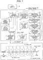
- Fig. 1 is a view which shows examples of configurations of a tandem rolling mill control device 10 and of a control object 50, according to an embodiment of the present invention.
- the tandem rolling mill control device 10 obtains signals indicative of various states from the control object 50 and outputs various control signals to the control object 50.
- signals connecting respective blocks are indicated by arrows regardless of the type and number of signals.
- the control object 50 is a hot strip tandem rolling mill provided with a finish mill 60.
- the finish mill 60 is configured by a plurality of rolling stands 61, rolls a roughing bar 65, which was rolled in a roughing mill (not shown) at a pre-stage and has a thickness of about 30 mm, for example, and produces a thin strip 63.
- the finish mill 60 has a configuration in which seven rolling stands 61 are continuously arranged, and the strip 63 (roughing bar 65) is rolled while being moved from the left to the right. Specifically, the strip 63 (roughing bar 65) is sequentially processed thinly by rolling in the respective rolling stands 61 (F 1 to F 7 ) and is discharged as an approximately 1 mm to 15 mm thickness strip 63 from an delivery of the rolling stand 61 (F 7 ).
- the finish mill 60 direct rolling of the roughing bar 65 and the strip 63 is performed by work rolls 62 of the respective rolling stands 61.
- the roughing bar 65 is sometimes referred to as other names such as a roughing bar, an incoming bar, a transfer bar, etc.
- the roll speed means a circumferential speed of the work roll 62.
- a multi gauge 64 that measures a strip thickness, a strip width, temperature, etc. of the strip 63 is disposed.
- various detectors for detecting the states of the roughing bar 65 and the strip 63 such as a thermometer measuring the temperature of the roughing bar 65 and strip 63, a shapemeter measuring flatness of the strip 63, a crop profile guage measuring head and tail end shape images of the roughing bar 65, a surface inspection equipment detecting a surface flaw of the strip 63, etc., are actually arranged in different places as needed.
- the tandem rolling mill control device 10 is configured to include a control reference setup section 11, a rolling result collection section 12, an inter-stand strip thickness calculation section 13, a roll force prediction error calculation section 14, a roll force balance consistency value calculation section 15, a roll force compensation value calculation section 16, a screw-down position control section 17, a roll speed control section 18, a draft schedule storage section 21, a speed pattern storage section 22, a roll force balance ratio storage section 23, a roll force compensation actual value storage section 24, etc.
- the control reference setup section 11 receives information required for rolling, such as the steel grade, target strip thickness, target strip width, etc. of the strip 63 to be rolled, which are transmitted from a host computer 40. Then, according to the received information, the roll force, screw-down position (roll gap), roll speed, etc. in each rolling stand 61 are calculated utilizing information and the like which is obtained from the draft schedule storage section 21 and the speed pattern storage section 22. Though the details will be described hereinafter, a roll force compensation value that is calculated in the roll force compensation value calculation section 16 is taken into consideration in this calculation of the roll force.
- the control reference setup section 11 further outputs calculation results of the roll force, screw-down position, roll speed, etc. in each rolling stand 61 to the screw-down position control section 17 and the roll speed control section 18, respectively, as control references of the screw-down position and roll speed. Then, on the basis of the control references, the screw-down position control section 17 outputs a control value for controlling the roll force and screw-down position to each rolling stand 61. Similarly, on the basis of a roll speed reference, the roll speed control section 18 outputs a control value for controlling the roll speed to each rolling stand 61.
- the rolling results collection section 12 collects a rolling-actual value of the strip, that is detected via the multi gauge 64 or the like, and control reference values (roll force, screw-down position, roll speed, etc.) that are outputted to the control object 50 from the screw-down position control section 17, the roll speed control section 18, etc.
- the inter-stand strip thickness calculation section 13 estimates an inter-stand strip thickness of the strip 63 among the respective rolling stands 61 utilizing the data which the rolling results collection section 12 collects. Moreover, the roll force prediction error calculation section 14 predicts roll forces of the respective rolling stands 61 utilizing the inter-stand strip thickness estimated in the inter-stand strip thickness calculation section 13, and calculates deviations between them and actual roll forces (hereinafter referred to as roll force prediction errors).
- the roll force balance consistency value calculation section 15 calculates a roll force balance consistency value for maintaining roll force balance among the respective rolling stands 61, utilizing a roll force prediction error of a remarkable rolling stand 61, a roll force prediction error of a rolling stand 61 neighboring thereto, and a ratio acquired from the roll force balance ratio storage section 23 (a roll force balance ratio referred to in Fig. 8 , etc.), among the roll force prediction errors calculated in the roll force prediction error calculation section 14.
- the roll force compensation value calculation section 16 calculates a roll force compensation value, that should be outputted to the control reference setup section 11, by utilizing the roll force prediction error calculated by the roll force prediction error calculation section 14, the roll force balance consistency value calculated by the roll force balance consistency value calculation section 15, and a roll force compensation value stored in the roll force compensation actual value storage section 24 and calculated in connection with the rolling in the past.
- tandem rolling mill control device 10 which is configured as described above is realized by a computer provided with an arithmetic processing unit and a storage unit, and a work station.
- Functions of the respective sections such as the control reference setup section 11, the rolling-results collection section 12, the inter-stand strip thickness calculation section 13, the roll force prediction error calculation section 14, the roll force balance consistency value calculation section 15, the roll force compensation value calculation section 16, the screw-down position control section 17, the roll speed control section 18, etc. which are shown in Fig. 1 are realized by execution of predetermined program stored in the storage unit comprising a semiconductor memory, a hard disk drive, etc., by the arithmetic processing unit.
- the storage sections such as the draft schedule storage section 21, the speed pattern storage section 22, the roll force balance ratio storage section 23, the roll force compensation actual value storage section 24, etc., are realized by storage of predetermined data into a region which is assigned to a part of the storage unit.
- Fig. 2 is a view illustrating an example of a processing flow of processing which the control reference setup section 11 executes.
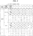
- Fig. 3 is a view illustrating an example of a configuration of a draft schedule table 211 that is stored in the draft schedule storage section 21
- Fig. 4 is a view illustrating an example of a configuration of a speed pattern table 221 that is stored in the speed pattern storage section 22.
- roll force in the respective rolling stands 61 and screw-down position of the work rolls 62 are required to be suitable in order to obtain a desired thickness of a head end portion of the strip 63 .
- the roll speeds of the respective rolling stands 61 are required to be well-balanced, without any disturbance of a mass flow of the strip 63 (product of the strip thickness and the strip speed).
- control reference setup section 11 receives information of the steel grade, target strip thickness, target strip width, etc. of the strip 63 to be rolled now, which are transmitted from the host computer 40, and calculates a control reference such as the screw-down position, the roll speed, etc. to be required in order to roll the strip 63 according to the target.
- the control reference setup section 11 first refers to the draft schedule table 211 (refer to Fig. 3 ) stored in the draft schedule table storage section 21 to acquire a draft schedule table corresponding to the steel grade, target strip thickness and target strip width of the strip, that is a rolling object, which are transmitted from the host computer 40, and calculates screw-down ratios of the respective rolling stands 61 (Step S11).
- the draft schedule table 211 is configured by a draft schedule in which the steel grade, target strip thickness, target strip width, etc. of the strip 63 to be rolled are categorized.
- the draft schedule is information indicating how much the roughing bar 65 or the strip 63 is rolled in each of the rolling stands 61 (F 1 to F 7 ), namely, information indicating a draft (ratio of a difference between an entry strip thickness and an delivery strip to the entry strip thickness) in percent.
- this strip 63 is categorized as a strip which has a target strip thickness of 2.0 to 3.0 mm and a target strip width equal to or less than 1000 mm. Therefore, the roughing bar 65 having a strip thickness of 35 mm is rolled by 14 mm equivalent to 40 % of the strip thickness thereof, and consequently, a strip 63 which has an delivery strip thickness of 21 mm is produced. Similarly, in the rolling stand 61 (F 2 ), the strip 63 having the entry strip thickness of 21 mm is rolled by 35% of the thickness thereof to make a strip 63 having an delivery strip thickness of 13.65 mm.
- the control reference setup section 11 refers to the speed pattern table 221 (refer to Fig. 4 ) stored in the speed pattern storage section 22 to acquire a speed pattern which correspond to the steel grade, target strip thickness, and target strip width of the strip 63 that is the rolling object, and calculates a rolling speed (strip speed) at the delivery of the final rolling stand 61 (F 7 ) (Step S12).
- the speed pattern table 221 is configured by a speed pattern table that is categorized by the steel grade, target strip thickness, target strip width, etc. of the strip 63 to be rolled.
- the speed pattern is information about a speed at the time when the strip 63 that is the rolling object is discharged from the final rolling stand 61 (F 7 ), for example, means information which comprises an initial speed, a first acceleration rate, a second acceleration rate, a regular speed, a deceleration rate, and a final speed.
- the initial speed is a speed at the time when the head end of the strip 63 is discharged from the final rolling stand 61 (F 7 )
- the first acceleration rate is an acceleration rate at the time when the speed of the strip 63 is increased after discharging of the head of the strip 63
- the second acceleration rate is an acceleration rate until the strip 63 reaches the regular speed after it is bitten by a down coiler (omitted in Fig.
- the deceleration rate is a deceleration rate at the time when the strip 63 stably passes through the respective rolling stands 61 and decelerated to the final speed
- the final speed is a speed at the time when a tail end of the strip 63 is discharged from the final rolling stand 61(F 7 ).
- the initial speed is 650 mpm (meter per minute)
- the first acceleration rate is 2 mpm/s
- the second acceleration rate is 12 mpm/s
- the regular speed is 1100 mpm
- the deceleration rate00 is 6 mpm/s
- the final speed is 700 mpm.
- the control reference setup section 11 executes processing to estimate temperature of the respective rolling stands 61 (Step S13).
- the temperature of the roughing bar 65 and strip 63 is estimated by combining temperature detected by thermometers (not shown in Fig. 1 ) installed at the respective sections of the control object 50, heat transfer by radiation, heat transfer, heat generation by plastic deformation due to deformation of the strip 63 by rolling, heat conduction between rolls that is taken away by roll surfaces at the time of rolling, etc.
- thermometers not shown in Fig. 1
- control reference setup section 11 calculates deformation resistance that is a value corresponding to hardness of the strip 63 to be rolled in the respective rolling stands 61 (Step S14).
- Methods of calculating deformation resistance are described in various literatures and described in detail in chapter 7 (Deformation Resistance) of the above-mentioned literature "Theory and Practice of Strip Rolling", for example.
- deformation resistance Kf can be calculated by the following formula (1).
- Kf k ⁇ ⁇ n ⁇ d ⁇ / dt m ⁇ exp A / T
- T rolling temperature of the strip 63 that is estimated
- ⁇ strain
- d ⁇ /dt a strain speed
- k, n, m, and A are constants depending upon the steel grade.
- Step S15 the control reference setup section 11 calculates roll speeds in respective rolling stands 61 (Step S15). Since the strip speed at the delivery of the final rolling stand 61 (F 7 ) is found in Step S12, here, on the basis of this, the strip speeds Vs i at the delivery of the respective rolling stand 61 is first calculated by using the following formula (2).
- Vs i Vs 7 ⁇ h i / h 7
- Vs i a strip speed at the delivery of the rolling stand (F i )
- Vs 7 is a strip speed at the delivery of the rolling stand (F 7 ) (final rolling stand)
- hi is a strip thickness at the delivery of the rolling stand (F i )
- h 7 is a strip thickness at the delivery of the rolling stand (F 7 ) (final rolling stand).
- the control reference setup section 11 calculates the roll speeds in the respective rolling stands 61 from the strip speeds Vs i at the deliveries of the respective rolling stands 61, using the concept of a forwarding slip.
- the forwarding slip is a value that corresponds to a ratio of circumferential speeds of the work rolls 62 to the delivery speeds of the strip 63 to be rolled in the work rolls 62.
- the forwarding slip f is expressed as a function of a plurality of parameters as shown in the following formula (3) (for details, refer to the above-mentioned literature "Theory and Practice of Strip Rolling").
- H is an entry strip thickness
- h is an delivery strip thickness
- R' is a deformed roll diameter
- Kf is deformation resistance
- tb entry tension
- tf delivery tension
- a roll speed Vri in the rolling stand 61 (Fi) can be calculated by the following formula (4), using the strip speed Vs i at the delivery of the rolling stand (Fi).
- Vr i Vs i / f i
- control reference setup section 11 calculates roll force prediction values P in the respective rolling stands 61 (Step S16).
- a formula for calculating the roll force prediction value P is expressed as a function of a plurality of parameters such as the following formula (5).
- P G w , Kf , Qp , tf , tb , R ′ , H , h , ⁇
- w is a strip width
- Kf deformation resistance
- Qp is a draft force function
- ⁇ is a friction coefficient
- tb entry tension
- tf delivery tension
- H is an entry strip thickness
- h is an delivery strip thickness
- R' is a deformed roll diameter
- the control reference setup section 11 calculates screw-down positions (roll gaps) of the work rolls 62 in the respective rolling stands 61 (Step S17).
- control reference setup section 11 outputs control references for the screw-down position and the roll speed, which are calculated with respect to the strip 63 to be rolled from now, to the screw-down position control section 17 and the roll speed control section 18.
- the screw-down position control section 17 executes the screw-down control with respect to the control reference of the screw-down position, which the control reference setup section 11 outputs, in such a manner that the screw-down positions of the work rolls 62 become a value pursuant to the control reference.
- the roll speed control section 18 executes the speed control with respect to the control reference of the roll speed, which the control reference setup section 11 outputs, in such a manner that the roll speeds of the work rolls 62 become a value pursuant to the control reference.
- processing in the control reference setup section 11 which has been described are executed with respect to the strip 63 to be rolled from now, processing in the inter-stand strip thickness calculation section 13, the roll force prediction error calculation section 14, the roll force balance consistency value calculation section 15, and the roll force compensation value calculation section 16 is executed utilizing various rolling actual values acquired through the rolling, at a timing as the rolling is finished.
- rolling to be executed in the processing is hereinafter referred to as the said rolling
- a strip 63 to be produced in the said rolling is hereinafter referred to as the said strip 63.
- Fig. 5 is a view illustrating an example of a processing flow of processing which the inter-stand strip thickness section 13 executes.
- the multi gauge 64 is disposed only at the delivery of the final rolling stand 61 (F 7 ) and is not disposed at a midway stage of the respective rolling stands 61 (F 1 to F 7 ). Therefore, the inter-stand strip thickness calculation section 13 estimates the strip thickness of the said strip 63 at an intermediate position of the respective rolling stands 61 (F 1 to F 7 ) (hereinafter referred to as an inter-stand strip thickness).
- a strip thickness to of the roughing bar 65 i.e., an entry strip thickness at the rolling stand 61 (F 1 ) is also estimated
- the inter-stand strip thickness calculation section 13 first acquire, via the rolling results collection section 12, an delivery strip thickness t 7 , detected by the multi gauge 64 disposed at the delivery of the final rolling stand 61 (F 7 ), and the roll speeds Vr 1 to Vr 7 of the work rolls 62 in the respective rolling stands 61 (F 1 to F 7 ) (Step S21).
- the inter-stand strip thickness estimation section 13 estimates an entry strip thickness t 6 from the delivery strip thickness t 7 at the rolling stand 61 (F 7 ) on the basis of a so-called constant mass-flow theory (Step S22).
- the mass flow constant regulation means that the product of the delivery strip thickness t i and an delivery strip speed Vs i at the rolling stand 61 (F i ) becomes equal to the product of an entry strip thickness and an entry strip speed (in short, an delivery strip thickness t i-1 and an delivery strip speed Vs i-1 ) at the rolling stand 61 (F i-1 ).
- the inter-stand strip thickness calculation section 13 calculates the entry strip thickness t 6 at the rolling stand 61 (F 7 ) on the basis of the following formula (7).
- this entry strip thickness t 6 corresponds to the inter-stand strip thickness t 6 between the rolling stand 61 (F 6 ) and the rolling stand 61 (F 7 ).
- t 6 t 7 ⁇ V 7 ⁇ 1 + f 7 / V 6 ⁇ 1 + f 6
- t 7 is the delivery strip thickness at the rolling stand (F 7 )
- V 7 is the roll speed of the work roll at the rolling stand (F 7 ) (circumferential speed)
- f 7 is the forwarding slip of the rolling stand (F 7 )
- V 6 is the roll speed of the work roll at the rolling stand (F 6 ) (circumferential speed)
- f 6 is the forwarding slip of the rolling stand (F 6 ).
- the forwarding slips f 6 , f 7 are calculated by the control reference setup section 11 according to the formula (3) prior to rolling of the said strip 63. Since the forwarding slips f 6 , f 7 are estimated and calculated, utilizing the formula (3), a value to be calculated includes a certain error. Therefore, the entry strip thickness t 6 that is calculated utilizing the forwarding slips f 6 , f 7 also includes an error.
- the inter-stand strip thickness t 6 between the rolling stand 61 (F 6 ) and the rolling stand 61 (F 7 ) are estimated as discussed above, and this inter-stand strip thickness t 6 is also the delivery strip thickness t 6 at the rolling stand 61 (F 6 ). Therefore, similarly to the Step S22, the inter-stand strip thickness calculation section 13 estimates an entry strip thickness t 5 at the rolling stand 61 (F 6 ) from the delivery strip thickness t 6 at the rolling stand 61 (F 6 ) (Step S23).
- the inter-stand strip thickness calculation section 13 estimates an entry strip thickness t 4 at the rolling stand 61 (F 5 ) (Step S24), estimates an entry strip thickness t 3 at the rolling stand 61 (F 4 ) (Step S25), estimates an entry strip thickness t 2 at the rolling stand 61 (F 3 ) (Step S26), estimates an entry strip thickness t 1 at the rolling stand 61 (F 2 ) (Step S27), and further estimates an entry strip thickness to at the rolling stand 61 (F 1 ) (Step S28).
- the entry strip thickness to corresponds to the strip thickness to of the roughing bar 65.
- the entry strip thicknesses at the respective rolling stands 61 may be also calculated at one time from a relationship among the measured rolling stand 61 (F 7 ), the forwarding slip f 7 of the rolling stand 61 (F 7 ), and the forwarding slips f i and roll speeds Vr i of the respective rolling stands 61 (F i ).
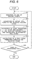
- Fig. 6 is a view illustrating an example of a processing flow of processing which the roll force prediction error calculation section 14 executes.
- the roll force prediction error calculation section 14 first selects one of the seven rolling stands 61 (F 1 to F 7 ) (Step S31).
- the order of the selection is not especially limited, for example, the selection may be performed in turn from the upstream rolling stand 61.
- the roll force prediction error calculation section 14 acquires, via the rolling-results collection section 12, an actual roll force at the selected rolling stand 61 (Step S32). Moreover, the roll force prediction error calculation section 14 acquires the entry strip thickness and delivery strip thickness at the selected rolling stand 61 from the inter-stand strip thickness calculation section 13, and calculates an estimated roll force at the rolling stand 61 according to the above formula (5) (Step S33).
- calculation of the strip width w and the deformation resistance Kf further requires rolling temperature and, as the rolling temperature, temperature is used which is estimated on the basis of a value that is detected by a temperature detector (not shown in Fig. 1 ), considering a distance between an installation position of the temperature detector and the said rolling stand 61, and the like.
- the roll force prediction error calculation section 14 calculates a roll force prediction error that is a ratio of the actual roll force acquired in Step S32 to the estimated roll force estimated in Step S33 (Step S34).
- a roll force prediction error Zpli of the rolling stand 61 (F i ) is calculated according to the following formula.
- Zpl i Pa i / Ps i where Pa i is an actual roll force at the rolling stand (F i ), and Ps i is an estimated roll force based on various actual values at the rolling stand (F i ).
- the roll force prediction error calculation section 14 determines whether or not the processing calculating the roll force prediction errors Zpli with respect to all rolling stands 61 (F 1 to F 7 ) is ended (Step S35) and, unless the processing is ended ("No" in Step S35), repeatedly executes the processing in Step S31 and the subsequent Steps. Moreover, if the processing calculating the roll force prediction errors Zpli with respect to all rolling stands 61 (F 1 to F 7 ) has been ended ("Yes" in Step S35), the processing calculating the roll force prediction errors Zpli with respect to the said strip 63 is ended.
- Fig. 7 is a view illustrating an example of a processing flow of processing which the roll force balance consistency value calculation section 15 executes.
- the roll force prediction values P in the respective rolling stands 61 are calculated with respect to a strip 63 to be next rolled.
- processing compensating the calculated roll force prediction values P is executed.
- the roll force prediction errors Zpli can be directly used as a roll force compensation value.
- the roll force prediction error Zpli is calculated per rolling stand 61, so that there is a case where they vary considerably among the plurality of rolling stands 61.
- the degree of compensation of the roll force prediction values P in the respective rolling stands 61 also varies.
- the compensated roll force prediction values P are actually used in calculation of the roll forces in the respective rolling stands 61, namely, in calculation of the screw-down positions. Therefore, even if the roll force prediction values P are compensated, if a variation is left between neighboring rolling stands 61, a problem that balance may be lost due the variation occurs. Therefore, in processing by the roll force balance consistency value calculation section 15 which will be explained hereinafter, a value for suppressing collapse of the balance between the neighboring rolling stands 61 (hereinafter referred to as a roll force balance consistency value) is calculated.
- the roll force balance consistency value calculation section 15 first selects one 61 (F i ) of the seven rolling stands 61 (F 1 to F 7 ) (Step S41). In this case, though the order of the selection is not especially limited, for example, the selection may be in turn performed from the upstream rolling stand 61.
- the roll force balance consistency value calculation section 15 acquires a roll force prediction error Zpli of the selected rolling stand 61 (F i ) from the processing-results in the roll force prediction error calculation section 14 (Step S42), and acquires a roll force prediction error Zpl i-+1 of the neighboring rolling stand 61 (F i-1 , F i+1 ) (Step S43).
- the neighboring rolling stands 61 (F i-1 , F i+1 ) mean the rolling stand 61 (F i-1 ) on the upstream of the rolling stand (F i ) and the rolling stand 61 (F i+1 ) on the downstream of the rolling stand (F i ).
- a rolling stand 61 which is neighboring to the upmost stream side rolling stand 61 (F 1 ) is the rolling stand 61 (F 2 ) only.
- a rolling stand 61 which is neighboring to the downmost stream side rolling stand 61 (F 7 ) is the rolling stand 61 (F 6 ) only.
- the rolling stand 61 which is neighboring to the rolling stand 61 (F 1 ) is indicated as the rolling stand 61 (F i-1 , F i+1 ) in this application.
- the roll force balance consistency value calculation section 15 calculates a roll force balance consistency value Zplb i of the selected rolling stand 61 according to the following formula (9), for example.
- Zplb i ⁇ ⁇ / Zpl i ⁇ 1 ⁇ Zpl i + Zpl i + 1 ⁇ Zpl i 4
- Zplb i ⁇ ⁇ Zpl i + 1 ⁇ Zpl i / 3
- Zplb i ⁇ ⁇ Zpl i ⁇ 1 ⁇ Zpl i / 3
- Zplb i ⁇ ⁇ Zpl i ⁇ 1 ⁇ Zpl i / 3
- Zpl i is the roll force prediction error
- ⁇ is the roll force balance ratio.
- the roll force balance consistency value Zplb i is equivalent to an average of differences between the roll force prediction error Zpli of the rolling stand 61 (F i ) and the roll force prediction errors Zpl i-1 , Zpl i+1 of the rolling stands (F i-1 , F i+1 ) neighboring thereto. Therefore, when the roll force prediction error Zpli of the rolling stand 61 (Fi) is larger than the roll force prediction errors Zpl i-1 , Zpl i+1 of the neighboring rolling stands 61 (F i-1 , F i+1 ), the roll force balance consistency value Zplb i becomes a negative value.
- the roll force balance consistency value Zplbi becomes a positive value.
- the roll force prediction error Zpl i of the rolling stand 61 (Fi) is substantially same to the roll force prediction errors Zpl i-1 , Zpl i+1 of the neighboring rolling stands 61 (F i-1 , F i+1 )
- the roll force balance consistency value Zplbi becomes a value close to 0 (zero).
- the roll force balance consistency value calculation section 15 determines whether or not the processing calculating the roll force balance consistency values Zplbi with respect to all rolling stands 61 (F 1 to F 7 ) is ended (Step S45) and, unless the processing is ended ("No" in Step S45), repeatedly executes the processing in Step S41 and the subsequent Steps. Moreover, if the processing calculating the roll force balance consistency values Zplbi with respect to all rolling stands 61 (F 1 to F 7 ) has been ended ("Yes" in Step S45), the processing calculating the roll force balance consistency values Zplb i with respect to the said strip 63 is ended.
- the roll force balance ratio ⁇ is a parameter that indicates how much ratio of compensation for the roll force prediction error Zpli to consistency of the roll force balance are to be balanced.
- the roll force balance ratio ⁇ is sored in the roll force balance ratio storage section 23.
- This roll force balance ratio ⁇ becomes a value between 0 and 1 and indicates that the consistency of the roll force balance is not consider when it is 0.
- ⁇ is 1, the consistency of the roll force balance is maximally considered.
- the roll force balance consistency value Zplbi is considered with a ratio equivalent to the roll force prediction error Zpl i .
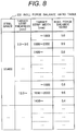
- Fig. 8 is view illustrating an example of a configuration of a roll force balance ratio table 231 which is stored in the roll force balance ratio storage section 23.
- the roll force balance ratio table 231 is configured by values of the roll force balance ratio ⁇ which are categorized by the steel grade, target strip thickness, target strip width, etc. of the strip 63 to be rolled.
- the roll force balance ratio ⁇ is 1.0.
- the target strip thickness is 12.0 mm
- the target strip width is 1400 mm or more
- the roll force balance ratio ⁇ is 0.4.
- Fig. 9 is a view illustrating an example of a processing flow of processing which the roll force compensation value calculation section 16 executes.
- the roll force compensation value calculation section 16 calculates roll force compensation values (a first roll force compensation value and a second roll force compensation value that will be hereinafter referred to) to be used when accuracy of the roll force prediction value which the control reference setup section 11 predicts is raised.
- the roll force compensation value calculation section 16 first selects one of the seven rolling stands 61 (F 1 to F 7 ) (Step S51). In this case, though the order of the selection is not especially limited, for example, the selection may be in turn performed from the upstream rolling stand 61.
- the roll force compensation value calculation section 16 acquires the roll force prediction error Zpli of the selected rolling stand 61 (Fi) from the processing-results in the roll force prediction error calculation section 14 (Step S52) and further acquires the roll force balance consistency value Zplbi of the selected rolling stand 61 (Fi) from the processing-results in the roll force balance consistency value calculation section 15 (Step S53).
- the roll force compensation value calculation section 16 calculates the first roll force compensation value Zpni corresponding to the said strip 63 in the selected rolling stand 61 (Fi) in accordance with the following formula (10) (Step S54).
- Zpn i Zpl i + Zplb i
- Zpni the first roll force compensation value
- Zpli is a roll force prediction error
- Zplbi the roll force balance consistency value.
- the roll force balance consistency value Zplbi is equivalent to an average of differences between the roll force prediction error Zpli of the rolling stand 61 (Fi) and the roll force prediction errors Zpl i-1 , Zpl i+1 of the rolling stands (F i-1 , F i+1 ) neighboring thereto. Therefore, when the roll force prediction error Zpl i of the rolling stand 61 (Fi) is larger than the roll force prediction errors Zpl i-1 , Zpl i+1 of the neighboring rolling stands 61 (F i-1 , F i+1 ), the roll force balance consistency value Zplbi becomes a negative value.
- the first roll force compensation value Zpn i is found by adding the roll force balance consistency value Zplbi to the roll force prediction error Zpli, so that the first roll force compensation value Zpni becomes smaller than the roll force prediction error Zpl i .
- a value of the first roll force compensation values Zpn i , Zpn i+1 of the neighboring rolling stands 61 (F i-1 , F i+1 ) whose roll force prediction errors Zpl i-1 , Zpl i+1 are relatively small reduces.
- a value of the first roll force compensation value Zpni of the rolling stand 61 (Fi) whose roll force prediction error Zpli is relatively large relative to the neighboring rolling stands 61 (F i-1 , F i+1 ) increase.
- the roll force balance consistency value Zplbi becomes a value close to 0, so that the first roll force compensation value Zpn i becomes a substantially same value as the roll force prediction error Zpl i .
- the roll force balance between the rolling stand 61 (F 1 ) and the neighboring rolling stands 61 (F i-1 , F i+1 ) is naturally maintained.
- the roll force compensation value calculation section 16 acquires, as processing subsequent to Step S54, a roll force compensation actual value Zpp i , that corresponds to the previous rolling results of the rolling stand 61 (F 1 ) selected in Step S51, from the roll force compensation actual value storage section 24 (Step S55).
- Fig. 10 is a view illustrating an example of a configuration of a roll force compensation actual value table 241 which is stored in the roll force compensation actual value storage section 24.
- the roll force compensation actual value table 241 is configured by roll force compensation actual values Zpp i of the respective rolling stands 61 (F i ) that are categorized by the steel grade, target strip thickness, target strip width, etc. of the said strip 63.
- the roll force compensation actual value Zpp i is a value that stores the second roll force compensation values Zp i of the respective rolling stands 61 (Fi) which are outputted to the control reference setup section 11 from the roll force compensation value calculation section (refer to Step 56) when the strips 63 belonging to the respective categories are rolled in the past.
- the roll force compensation actual values Zpp i which respectively corresponds to 1.11, 1.08, 0.94, 0.98, 1.04, 0.99, and 1.03.
- the roll force compensation value calculation section 16 calculates, as processing subsequent to Step S55, a second roll force compensation value Zp i with respect to the rolling stand 61 (F i ) selected in Step S51 in accordance with the following formula (11), and output the calculated second roll force compensation value Zp i to the control reference setup section 11 (Step S56).
- Zp i ⁇ ⁇ Zpn i + 1 ⁇ ⁇ ⁇ Zpp i
- Zp i the second roll force compensation value of the rolling stand (F i )
- Zpni the first roll force compensation value of the rolling stand (F i )
- Zpp i the roll force compensation actual value of the rolling stand (F i )
- ⁇ is a distribution coefficient.
- the distribution coefficient ⁇ is a coefficient that, when the second roll force compensation value Zpi of the rolling stand 61 (Fi) is calculated, determines a distribution ratio between the roll force compensation actual value Zpp i based on the previous rolling results stored in the roll force compensation actual value storage section 24, and the first roll force compensation value Zpn i calculated in connection with rolling of the strip 63 in the immediate past (hereinafter, the immediate past means the closest past), and becomes a value between 0 and 1.
- the distribution coefficient ⁇ is 0, the first roll force compensation value Zpni estimated in connection with rolling of the said strip 63 is ignored and the second roll force compensation value Zp i is determined according to the roll force compensation actual value Zpp i based on the previous rolling results stored in the roll force compensation actual value storage section 24.
- the distribution coefficient ⁇ is 1, the roll force compensation actual value Zpp i based on the previous rolling results is ignored and the second roll force compensation value Zp i is determined according to the first roll force compensation value Zpni estimated in connection with rolling of the said strip 63.
- the roll force compensation value calculation section 16 causes the second roll force compensation values Zpi of the rolling stand 61 which it calculates in Step S56 and outputs to the control reference setup section 11, to be stored in the roll force compensation actual value storage section 24 as the roll force compensation actual values Zpp i of the rolling stand 61 (F i ) which it selects in the category to which the said strip 63 belongs (Step S57).
- the roll force compensation value calculation section 16 determines whether or not the processing from the Step S51 to the Step S57 in connection with all rolling stands 61 (F 1 and F 7 ) has been ended (Step S58) and, unless the processing has been ended ("No" in Step S58), repeatedly executes the processing in Step S51 and the subsequent Steps. Also, if the processing from the Step S51 to the Step S57 in connection with all rolling stands 61 (F 1 to F 7 ) has been ended ("Yes" in Step S58), the processing that calculates the second roll force compensation value Zp i and the like and is shown in Fig. 9 is ended.
- the second roll force compensation value Zp i that is calculated as discussed above and outputted to the control reference setup section 11 is used for improving the prediction accuracy of the roll force prediction value P in the control reference setup section 11.
- the control reference setup section 11 calculates the roll force prediction value P in accordance with the formula (5) and, when receiving the second roll force compensation value Zp i from the roll force compensation value calculation section 16, compensates the roll force prediction value P, estimated utilizing the formula (5), by the second roll force compensation value Zp i .
- the control reference setup section 11 calculates a roll force setting value Pseti for calculation of the screw-down position references and the like with respect to the respective rolling stands 61 (F i ), in accordance with the following formula (12).
- Pset i Zp i ⁇ G w i , Kf i , Qp i , tf i , tb i , R ′ i , H i , h i , ⁇ i
- w i , Kf i , Zp i , tf i , tb i , R' i , H i , hi, and ⁇ i are the strip width of the strip 63 in the respective rolling stands 61 (F i ), the deformation resistance, the draft force function, the entry tension, the delivery tension, the deformed roll diameter, the entry strip thickness, the delivery strip thickness, and the friction coefficient, respectively.
- the roll force balance ratio ⁇ is used in the calculation in the roll force balance consistency value calculation section 15 (refer to the formula (9).
- the following formula (13) is substituted for the formula (10) and may be used in the processing in the roll force compensation value calculation section 16.
- Zpn i Zpl i + ⁇ ⁇ Zplb i
- Zpn i the first roll force compensation value
- Zpli the roll force prediction error
- Zplbi is the roll force balance consistency value.
- the roll force balance consistency values Zplbi of the respective rolling stands 61 (Fi) are calculated depending upon the magnitude relationship between the roll force prediction error Zpli in the rolling stand 61 (Fi) and the roll force prediction errors Zpl i-1 , Zpl i+1 in the neighboring rolling stands 61 (F i-1 , F i+1 ) (refer to the formula (9)).
- the roll force prediction error Zli in the rolling stand 61 (Fi) is larger than the roll force prediction errors Zpl i-1 , Zpl i+1 in the neighboring rolling stands 61 (F i-1 , F i+1 )
- the balance consistency value Zplbi becomes a negative value.
- the first roll force compensation value Zpn i that is obtained by adding the roll force balance consistency value Zpibi to the roll force prediction error Zpli (refer to the formula (10)) results in suppression of the variation in the roll force prediction error Zpli.
- the second roll force compensation value Zp i (refer to the formula (11)) is found.
- the roll force setting value Pset i that is actually set to the rolling stand 61 (Fi) is calculated (refer to the formula (12)). Therefore, even if any variation in the roll force prediction value Pi is generated, the variation is suppressed in the roll force setting value Pseti. Therefore, in the embodiment of the present invention, the problem that the roll force balance among the plurality of rolling stands 61 (F i ) collapses is prevented from occurring.
- the roll force compensation value (the second roll force compensation value Zp i ) of the rolling stand 61 (Fi) is basically determined, depending only upon the magnitude relationship of the roll force prediction error Zpli of the rolling stand 61 (Fi) and the roll force prediction errors Zpl i-1 , Zpl i+1 of the neighboring rolling stands 61 (F i-1 , F i+1 ). Therefore, it is unnecessary to configure the roll force error change model like the one disclosed in Patent Literature 3, for example. Namely, in the embodiment of the present invention, an effect of allowing the roll force balance consistency among the plurality of rolling stands 61 (F i ) with simple processing is expected.
- the roll force error change model disclosed in, for example, the Patent Literature 3 is a linear model
- the variation of the roll force prediction error Zpli in the embodiment of the present invention is not limited to the linear model and can respond to various variation modes.
- the tandem rolling mill control device 10 when prior to rolling of the strip 63, the roll forces in the respective rolling stands 61 (Fi) that roll the strip 63 to a desired strip thickness are predicted, it is possible to estimate the roll forces with high accuracy, using simple calculation processing and considering the roll force balance among the plurality of rolling stands 61 (F i ). As a result, the strip which has a thickness with higher accuracy can be obtained, and the rolling can be stabilized.
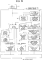
- Fig. 11 is a view illustrating an example of a configuration of a tandem rolling mill control device 10a according to a second embodiment of the present invention.
- the configuration of the tandem rolling mill control device 10a according to the second embodiment is different from that of the tandem rolling mill control device 10 of Fig. 1 in that it further includes a steel grade-similarity calculation section 31, a distribution coefficient calculation section 32, and a similarity-number storage section 35 which are newly added. Only this difference will be explained hereinafter.
- components which are similar to those of the tandem rolling mill control device 10 of Fig. 1 are denoted by like reference signs.
- the distribution coefficient ⁇ used in the formula (11) is made variable according to similarity numbers of strips 63 rolled one after the other.
- the steel grade-similarity calculation section 31 refers to the similarity-number storage section 35 to acquire their similarity-numbers and outputs them to the distribution coefficient calculation section 32.
- the distribution coefficient calculation section 32 calculates the distribution coefficient ⁇ on the basis of the similarity-numbers of the last and next strips 63, which it acquires from the steel grade-similarity calculation section 31, and outputs the distribution coefficient ⁇ to the roll force compensation value calculation section 16.
- the roll force compensation value calculation section 16 executes the calculation of the formula (11) using the distribution coefficient ⁇ which it receives from the distribution coefficient calculation section 32.
- Fig. 12 is a view illustrating an example of a processing flow of processing which the steel grade-similarity calculation section 31 executes.
- Fig. 13 is a view illustrating an example of a similarity-number table 351 which is stored in the similarity-number storage section 35.
- the similarity-number table 351 is configured by defining similarity-numbers with respect to the respective steel grades of the strips 63.
- the similarity-number of a strip 63 whose steel grade is SS400 is 4 and the similarity-number of a strip 63 whose steel grade is SS490 is 5. Therefore, it can be said that these steel plats 63 are very close in similarity of steel grades thereof.
- the similarity-number of a strip 63 whose steel grade is SS400 is 4 and the similarity-number of a strip 63 whose steel grade is SPHC is 2. Therefore, similarity of these strips 63 in steel grades is not as high as that of the strip 63 whose steel grade is SS400 and of the strip 63 whose steel grade is 490.
- the steel grade-similarity calculation section 31 refers to the similarity-number storage section 35 to acquire a steel grade-similarity number and a steel grade similarity number which correspond to the steel grade of a strip 63 rolled in the immediate past and the steel grade of a strip to be next rolled, respectively (Step S51).
- a similarity V is calculated from a difference between the similarity-numbers of the two strips 63 in accordance with the following formula (14) (Step S52).
- the smaller the value of the similarity V defined in the formula (14) is, the larger the similarity is, and the larger the value is, the smaller the similarity is.
- V Vn i ⁇ Vn j
- Vni is the similarity-number of the steel grade of the strip 63 rolled in the immediate past
- Vn j is the similarity-number of the steel grade of the strip 63 to be next rolled.
- the steel grade-similarity calculation section 31 outputs the selected similarity V to the distribution coefficient calculation section 32 (Step S53) and ends the processing.
- the distribution coefficient ⁇ becomes a value close to 0.
- the similarity V is smaller than Vc
- the distribution coefficient ⁇ is 0.
- the calculation of the formula (11) is performed using this distribution coefficient ⁇ .
- the second embodiment which has been discussed above is the example in which the calculation of the distribution coefficient is concretely performed using the distribution coefficient ⁇ used in the formula (11) and whose effect is substantially identical to that of the above-mentioned embodiment.
- tandem rolling mill control devices 10, 10a of the above-mentioned embodiment and second embodiment of the present invention are applied to hot-rolling, they can be applied to cold-rolling.
Landscapes
- Engineering & Computer Science (AREA)
- Mechanical Engineering (AREA)
- Control Of Metal Rolling (AREA)
Applications Claiming Priority (1)
| Application Number | Priority Date | Filing Date | Title |
|---|---|---|---|
| JP2014206616A JP6315818B2 (ja) | 2014-10-07 | 2014-10-07 | タンデム圧延ミルの制御装置および制御方法 |
Publications (2)
| Publication Number | Publication Date |
|---|---|
| EP3006126A1 EP3006126A1 (en) | 2016-04-13 |
| EP3006126B1 true EP3006126B1 (en) | 2017-08-02 |
Family
ID=54260664
Family Applications (1)
| Application Number | Title | Priority Date | Filing Date |
|---|---|---|---|
| EP15188340.2A Active EP3006126B1 (en) | 2014-10-07 | 2015-10-05 | Tandem rolling mill comprising a control device and control method |
Country Status (3)
| Country | Link |
|---|---|
| EP (1) | EP3006126B1 (ja) |
| JP (1) | JP6315818B2 (ja) |
| CN (1) | CN105478490B (ja) |
Families Citing this family (7)
| Publication number | Priority date | Publication date | Assignee | Title |
|---|---|---|---|---|
| JP6670261B2 (ja) * | 2017-02-23 | 2020-03-18 | 株式会社日立製作所 | タンデム圧延ミル制御装置およびタンデム圧延ミル制御方法 |
| CN110621422B (zh) * | 2017-05-26 | 2021-03-23 | 东芝三菱电机产业系统株式会社 | 串列轧机的尾端蛇行控制装置 |
| JP2020131248A (ja) * | 2019-02-21 | 2020-08-31 | Jfeスチール株式会社 | 圧延荷重予測方法、圧延荷重予測装置、及び圧延制御方法 |
| CN111400928B (zh) * | 2020-04-03 | 2023-09-15 | 首钢智新迁安电磁材料有限公司 | 一种基于多元回归的轧制力补偿方法及装置 |
| KR20220085047A (ko) * | 2020-11-16 | 2022-06-21 | 도시바 미쓰비시덴키 산교시스템 가부시키가이샤 | 연속 압연 시스템 |
| CN112711867B (zh) * | 2021-01-19 | 2023-04-18 | 苏州大学 | 融合理论模型和大数据模型的轧制力预测方法 |
| CN114367545B (zh) * | 2021-12-09 | 2023-09-08 | 北京首钢自动化信息技术有限公司 | 一种轧制力的修正方法和装置 |
Family Cites Families (12)
| Publication number | Priority date | Publication date | Assignee | Title |
|---|---|---|---|---|
| JPS5588911A (en) * | 1978-12-27 | 1980-07-05 | Kobe Steel Ltd | Controlling method for roll gap in tandem rolling |
| JPS60244413A (ja) * | 1984-05-16 | 1985-12-04 | Mitsubishi Electric Corp | 連続圧延機における負荷配分制御方法 |
| JPH02211905A (ja) * | 1989-02-09 | 1990-08-23 | Sumitomo Metal Ind Ltd | 熱間連続圧延機における圧下位置設定方法 |
| JPH0399710A (ja) * | 1989-09-14 | 1991-04-24 | Toshiba Corp | 圧延機のパススケジュールの設定方法および装置 |
| JP3467677B2 (ja) | 1997-03-25 | 2003-11-17 | Jfeスチール株式会社 | 圧延機における圧延荷重の学習制御方法 |
| JPH11244920A (ja) * | 1998-03-04 | 1999-09-14 | Hitachi Ltd | タンデム圧延機制御装置 |
| JP2007245204A (ja) * | 2006-03-16 | 2007-09-27 | Jfe Steel Kk | 圧延荷重モデルの学習方法及びその装置 |
| JP2009113101A (ja) * | 2007-11-09 | 2009-05-28 | Jfe Steel Corp | 圧延荷重の学習制御方法および装置、ならびに鋼板の製造方法 |
| BRPI0903494A2 (pt) * | 2008-03-14 | 2015-09-22 | Nippon Steel Corp | método de aprendizagem de predição de carga de laminação para laminação a quente |
| EP2431105A1 (de) * | 2010-09-16 | 2012-03-21 | Siemens Aktiengesellschaft | Ermittlungsverfahren für Steuergrößen einer Walzstraße mit mehreren Walzgerüsten zum Walzen eines Metallbandes |
| JP6020263B2 (ja) | 2012-03-29 | 2016-11-02 | Jfeスチール株式会社 | 圧延荷重の学習制御装置および学習制御方法、並びにこれを用いた金属板製造方法 |
| JP6025553B2 (ja) * | 2012-12-26 | 2016-11-16 | 株式会社日立製作所 | 圧延制御装置、圧延制御方法および圧延制御プログラム |
-
2014
- 2014-10-07 JP JP2014206616A patent/JP6315818B2/ja active Active
-
2015
- 2015-09-30 CN CN201510641106.4A patent/CN105478490B/zh active Active
- 2015-10-05 EP EP15188340.2A patent/EP3006126B1/en active Active
Also Published As
| Publication number | Publication date |
|---|---|
| JP6315818B2 (ja) | 2018-04-25 |
| CN105478490B (zh) | 2019-05-21 |
| CN105478490A (zh) | 2016-04-13 |
| JP2016074008A (ja) | 2016-05-12 |
| EP3006126A1 (en) | 2016-04-13 |
Similar Documents
| Publication | Publication Date | Title |
|---|---|---|
| EP3006126B1 (en) | Tandem rolling mill comprising a control device and control method | |
| JP4452323B2 (ja) | 熱間での板圧延における圧延負荷予測の学習方法 | |
| EP3031541B1 (en) | Control system of tandem rolling mill and control method of tandem rolling mill | |
| JP6025553B2 (ja) | 圧延制御装置、圧延制御方法および圧延制御プログラム | |
| JP3844280B2 (ja) | 板圧延における圧下レベリング設定方法 | |
| JP5239728B2 (ja) | 金属板材の圧延方法及び圧延装置 | |
| JP5783925B2 (ja) | 熱間タンデム圧延ミルの制御装置および熱間タンデム圧延ミルの制御方法 | |
| JP5251427B2 (ja) | 金属板材の板厚制御装置及び塑性係数推定用関数設定方法 | |
| JP4903676B2 (ja) | 金属板材の圧延方法および圧延装置 | |
| JP6620777B2 (ja) | 圧延機のレベリング設定方法および圧延機のレベリング設定装置 | |
| JP4948301B2 (ja) | 冷間圧延における形状制御方法 | |
| JP2001269706A (ja) | 連続冷間圧延時の形状制御方法 | |
| JP4986463B2 (ja) | 冷間圧延における形状制御方法 | |
| JP6670261B2 (ja) | タンデム圧延ミル制御装置およびタンデム圧延ミル制御方法 | |
| JPH1110215A (ja) | 熱間圧延材のウエッジ制御方法 | |
| JP3666340B2 (ja) | 熱間連続圧延機における板厚制御方法 | |
| KR101462332B1 (ko) | 압연기의 압연속도 제어장치 및 방법 | |
| JPH048122B2 (ja) | ||
| JPH0636929B2 (ja) | 被圧延材の板幅制御方法 | |
| JP2002346616A (ja) | 板厚制御方法 | |
| JP6601451B2 (ja) | 圧延機の制御方法、圧延機の制御装置、および熱延鋼板の製造方法 | |
| JPH01233004A (ja) | タンデムミルの制御方法及び装置 | |
| JP2950182B2 (ja) | テーパー鋼板の製造方法 | |
| JP2001347308A (ja) | 圧延機のパススケジュール設定方法及びその装置 | |
| JPH0899103A (ja) | 板圧延における板クラウンおよび形状制御方法 |
Legal Events
| Date | Code | Title | Description |
|---|---|---|---|
| PUAI | Public reference made under article 153(3) epc to a published international application that has entered the european phase |
Free format text: ORIGINAL CODE: 0009012 |
|
| 17P | Request for examination filed |
Effective date: 20160115 |
|
| AK | Designated contracting states |
Kind code of ref document: A1 Designated state(s): AL AT BE BG CH CY CZ DE DK EE ES FI FR GB GR HR HU IE IS IT LI LT LU LV MC MK MT NL NO PL PT RO RS SE SI SK SM TR |
|
| AX | Request for extension of the european patent |
Extension state: BA ME |
|
| GRAP | Despatch of communication of intention to grant a patent |
Free format text: ORIGINAL CODE: EPIDOSNIGR1 |
|
| INTG | Intention to grant announced |
Effective date: 20170215 |
|
| GRAS | Grant fee paid |
Free format text: ORIGINAL CODE: EPIDOSNIGR3 |
|
| GRAA | (expected) grant |
Free format text: ORIGINAL CODE: 0009210 |
|
| AK | Designated contracting states |
Kind code of ref document: B1 Designated state(s): AL AT BE BG CH CY CZ DE DK EE ES FI FR GB GR HR HU IE IS IT LI LT LU LV MC MK MT NL NO PL PT RO RS SE SI SK SM TR |
|
| REG | Reference to a national code |
Ref country code: CH Ref legal event code: EP Ref country code: AT Ref legal event code: REF Ref document number: 913883 Country of ref document: AT Kind code of ref document: T Effective date: 20170815 |
|
| REG | Reference to a national code |
Ref country code: IE Ref legal event code: FG4D |
|
| REG | Reference to a national code |
Ref country code: DE Ref legal event code: R096 Ref document number: 602015003857 Country of ref document: DE |
|
| REG | Reference to a national code |
Ref country code: NL Ref legal event code: MP Effective date: 20170802 |
|
| REG | Reference to a national code |
Ref country code: AT Ref legal event code: MK05 Ref document number: 913883 Country of ref document: AT Kind code of ref document: T Effective date: 20170802 |
|
| REG | Reference to a national code |
Ref country code: LT Ref legal event code: MG4D |
|
| PG25 | Lapsed in a contracting state [announced via postgrant information from national office to epo] |
Ref country code: NO Free format text: LAPSE BECAUSE OF FAILURE TO SUBMIT A TRANSLATION OF THE DESCRIPTION OR TO PAY THE FEE WITHIN THE PRESCRIBED TIME-LIMIT Effective date: 20171102 Ref country code: LT Free format text: LAPSE BECAUSE OF FAILURE TO SUBMIT A TRANSLATION OF THE DESCRIPTION OR TO PAY THE FEE WITHIN THE PRESCRIBED TIME-LIMIT Effective date: 20170802 Ref country code: NL Free format text: LAPSE BECAUSE OF FAILURE TO SUBMIT A TRANSLATION OF THE DESCRIPTION OR TO PAY THE FEE WITHIN THE PRESCRIBED TIME-LIMIT Effective date: 20170802 Ref country code: SE Free format text: LAPSE BECAUSE OF FAILURE TO SUBMIT A TRANSLATION OF THE DESCRIPTION OR TO PAY THE FEE WITHIN THE PRESCRIBED TIME-LIMIT Effective date: 20170802 Ref country code: FI Free format text: LAPSE BECAUSE OF FAILURE TO SUBMIT A TRANSLATION OF THE DESCRIPTION OR TO PAY THE FEE WITHIN THE PRESCRIBED TIME-LIMIT Effective date: 20170802 Ref country code: HR Free format text: LAPSE BECAUSE OF FAILURE TO SUBMIT A TRANSLATION OF THE DESCRIPTION OR TO PAY THE FEE WITHIN THE PRESCRIBED TIME-LIMIT Effective date: 20170802 Ref country code: AT Free format text: LAPSE BECAUSE OF FAILURE TO SUBMIT A TRANSLATION OF THE DESCRIPTION OR TO PAY THE FEE WITHIN THE PRESCRIBED TIME-LIMIT Effective date: 20170802 |
|
| PG25 | Lapsed in a contracting state [announced via postgrant information from national office to epo] |
Ref country code: PL Free format text: LAPSE BECAUSE OF FAILURE TO SUBMIT A TRANSLATION OF THE DESCRIPTION OR TO PAY THE FEE WITHIN THE PRESCRIBED TIME-LIMIT Effective date: 20170802 Ref country code: RS Free format text: LAPSE BECAUSE OF FAILURE TO SUBMIT A TRANSLATION OF THE DESCRIPTION OR TO PAY THE FEE WITHIN THE PRESCRIBED TIME-LIMIT Effective date: 20170802 Ref country code: IS Free format text: LAPSE BECAUSE OF FAILURE TO SUBMIT A TRANSLATION OF THE DESCRIPTION OR TO PAY THE FEE WITHIN THE PRESCRIBED TIME-LIMIT Effective date: 20171202 Ref country code: ES Free format text: LAPSE BECAUSE OF FAILURE TO SUBMIT A TRANSLATION OF THE DESCRIPTION OR TO PAY THE FEE WITHIN THE PRESCRIBED TIME-LIMIT Effective date: 20170802 Ref country code: LV Free format text: LAPSE BECAUSE OF FAILURE TO SUBMIT A TRANSLATION OF THE DESCRIPTION OR TO PAY THE FEE WITHIN THE PRESCRIBED TIME-LIMIT Effective date: 20170802 Ref country code: BG Free format text: LAPSE BECAUSE OF FAILURE TO SUBMIT A TRANSLATION OF THE DESCRIPTION OR TO PAY THE FEE WITHIN THE PRESCRIBED TIME-LIMIT Effective date: 20171102 Ref country code: GR Free format text: LAPSE BECAUSE OF FAILURE TO SUBMIT A TRANSLATION OF THE DESCRIPTION OR TO PAY THE FEE WITHIN THE PRESCRIBED TIME-LIMIT Effective date: 20171103 |
|
| PG25 | Lapsed in a contracting state [announced via postgrant information from national office to epo] |
Ref country code: DK Free format text: LAPSE BECAUSE OF FAILURE TO SUBMIT A TRANSLATION OF THE DESCRIPTION OR TO PAY THE FEE WITHIN THE PRESCRIBED TIME-LIMIT Effective date: 20170802 Ref country code: RO Free format text: LAPSE BECAUSE OF FAILURE TO SUBMIT A TRANSLATION OF THE DESCRIPTION OR TO PAY THE FEE WITHIN THE PRESCRIBED TIME-LIMIT Effective date: 20170802 Ref country code: CZ Free format text: LAPSE BECAUSE OF FAILURE TO SUBMIT A TRANSLATION OF THE DESCRIPTION OR TO PAY THE FEE WITHIN THE PRESCRIBED TIME-LIMIT Effective date: 20170802 |
|
| REG | Reference to a national code |
Ref country code: DE Ref legal event code: R097 Ref document number: 602015003857 Country of ref document: DE |
|
| PG25 | Lapsed in a contracting state [announced via postgrant information from national office to epo] |
Ref country code: MC Free format text: LAPSE BECAUSE OF FAILURE TO SUBMIT A TRANSLATION OF THE DESCRIPTION OR TO PAY THE FEE WITHIN THE PRESCRIBED TIME-LIMIT Effective date: 20170802 Ref country code: SM Free format text: LAPSE BECAUSE OF FAILURE TO SUBMIT A TRANSLATION OF THE DESCRIPTION OR TO PAY THE FEE WITHIN THE PRESCRIBED TIME-LIMIT Effective date: 20170802 Ref country code: IT Free format text: LAPSE BECAUSE OF FAILURE TO SUBMIT A TRANSLATION OF THE DESCRIPTION OR TO PAY THE FEE WITHIN THE PRESCRIBED TIME-LIMIT Effective date: 20170802 Ref country code: EE Free format text: LAPSE BECAUSE OF FAILURE TO SUBMIT A TRANSLATION OF THE DESCRIPTION OR TO PAY THE FEE WITHIN THE PRESCRIBED TIME-LIMIT Effective date: 20170802 Ref country code: SK Free format text: LAPSE BECAUSE OF FAILURE TO SUBMIT A TRANSLATION OF THE DESCRIPTION OR TO PAY THE FEE WITHIN THE PRESCRIBED TIME-LIMIT Effective date: 20170802 |
|
| PLBE | No opposition filed within time limit |
Free format text: ORIGINAL CODE: 0009261 |
|
| STAA | Information on the status of an ep patent application or granted ep patent |
Free format text: STATUS: NO OPPOSITION FILED WITHIN TIME LIMIT |
|
| 26N | No opposition filed |
Effective date: 20180503 |
|
| REG | Reference to a national code |
Ref country code: IE Ref legal event code: MM4A |
|
| REG | Reference to a national code |
Ref country code: FR Ref legal event code: ST Effective date: 20180629 |
|
| PG25 | Lapsed in a contracting state [announced via postgrant information from national office to epo] |
Ref country code: LU Free format text: LAPSE BECAUSE OF NON-PAYMENT OF DUE FEES Effective date: 20171005 |
|
| REG | Reference to a national code |
Ref country code: BE Ref legal event code: MM Effective date: 20171031 |
|
| PG25 | Lapsed in a contracting state [announced via postgrant information from national office to epo] |
Ref country code: BE Free format text: LAPSE BECAUSE OF NON-PAYMENT OF DUE FEES Effective date: 20171031 Ref country code: FR Free format text: LAPSE BECAUSE OF NON-PAYMENT OF DUE FEES Effective date: 20171031 Ref country code: SI Free format text: LAPSE BECAUSE OF FAILURE TO SUBMIT A TRANSLATION OF THE DESCRIPTION OR TO PAY THE FEE WITHIN THE PRESCRIBED TIME-LIMIT Effective date: 20170802 |
|
| PG25 | Lapsed in a contracting state [announced via postgrant information from national office to epo] |
Ref country code: MT Free format text: LAPSE BECAUSE OF NON-PAYMENT OF DUE FEES Effective date: 20171005 |
|
| PG25 | Lapsed in a contracting state [announced via postgrant information from national office to epo] |
Ref country code: IE Free format text: LAPSE BECAUSE OF NON-PAYMENT OF DUE FEES Effective date: 20171005 |
|
| REG | Reference to a national code |
Ref country code: CH Ref legal event code: PL |
|
| PG25 | Lapsed in a contracting state [announced via postgrant information from national office to epo] |
Ref country code: HU Free format text: LAPSE BECAUSE OF FAILURE TO SUBMIT A TRANSLATION OF THE DESCRIPTION OR TO PAY THE FEE WITHIN THE PRESCRIBED TIME-LIMIT; INVALID AB INITIO Effective date: 20151005 |
|
| PG25 | Lapsed in a contracting state [announced via postgrant information from national office to epo] |
Ref country code: LI Free format text: LAPSE BECAUSE OF NON-PAYMENT OF DUE FEES Effective date: 20181031 Ref country code: CH Free format text: LAPSE BECAUSE OF NON-PAYMENT OF DUE FEES Effective date: 20181031 |
|
| PG25 | Lapsed in a contracting state [announced via postgrant information from national office to epo] |
Ref country code: CY Free format text: LAPSE BECAUSE OF FAILURE TO SUBMIT A TRANSLATION OF THE DESCRIPTION OR TO PAY THE FEE WITHIN THE PRESCRIBED TIME-LIMIT Effective date: 20170802 |
|
| PG25 | Lapsed in a contracting state [announced via postgrant information from national office to epo] |
Ref country code: MK Free format text: LAPSE BECAUSE OF FAILURE TO SUBMIT A TRANSLATION OF THE DESCRIPTION OR TO PAY THE FEE WITHIN THE PRESCRIBED TIME-LIMIT Effective date: 20170802 |
|
| PG25 | Lapsed in a contracting state [announced via postgrant information from national office to epo] |
Ref country code: TR Free format text: LAPSE BECAUSE OF FAILURE TO SUBMIT A TRANSLATION OF THE DESCRIPTION OR TO PAY THE FEE WITHIN THE PRESCRIBED TIME-LIMIT Effective date: 20170802 |
|
| PG25 | Lapsed in a contracting state [announced via postgrant information from national office to epo] |
Ref country code: PT Free format text: LAPSE BECAUSE OF FAILURE TO SUBMIT A TRANSLATION OF THE DESCRIPTION OR TO PAY THE FEE WITHIN THE PRESCRIBED TIME-LIMIT Effective date: 20170802 |
|
| PG25 | Lapsed in a contracting state [announced via postgrant information from national office to epo] |
Ref country code: AL Free format text: LAPSE BECAUSE OF FAILURE TO SUBMIT A TRANSLATION OF THE DESCRIPTION OR TO PAY THE FEE WITHIN THE PRESCRIBED TIME-LIMIT Effective date: 20170802 |
|
| GBPC | Gb: european patent ceased through non-payment of renewal fee |
Effective date: 20191005 |
|
| PG25 | Lapsed in a contracting state [announced via postgrant information from national office to epo] |
Ref country code: GB Free format text: LAPSE BECAUSE OF NON-PAYMENT OF DUE FEES Effective date: 20191005 |
|
| PGFP | Annual fee paid to national office [announced via postgrant information from national office to epo] |
Ref country code: DE Payment date: 20230830 Year of fee payment: 9 |