EP3003937B1 - Aufspulmaschine - Google Patents
Aufspulmaschine Download PDFInfo
- Publication number
- EP3003937B1 EP3003937B1 EP14722218.6A EP14722218A EP3003937B1 EP 3003937 B1 EP3003937 B1 EP 3003937B1 EP 14722218 A EP14722218 A EP 14722218A EP 3003937 B1 EP3003937 B1 EP 3003937B1
- Authority
- EP
- European Patent Office
- Prior art keywords
- winding
- traversing plate
- traversing
- winding machine
- plate
- Prior art date
- Legal status (The legal status is an assumption and is not a legal conclusion. Google has not performed a legal analysis and makes no representation as to the accuracy of the status listed.)
- Active
Links
Images


Classifications
-
- B—PERFORMING OPERATIONS; TRANSPORTING
- B65—CONVEYING; PACKING; STORING; HANDLING THIN OR FILAMENTARY MATERIAL
- B65H—HANDLING THIN OR FILAMENTARY MATERIAL, e.g. SHEETS, WEBS, CABLES
- B65H54/00—Winding, coiling, or depositing filamentary material
- B65H54/02—Winding and traversing material on to reels, bobbins, tubes, or like package cores or formers
- B65H54/10—Winding and traversing material on to reels, bobbins, tubes, or like package cores or formers for making packages of specified shapes or on specified types of bobbins, tubes, cores, or formers
- B65H54/20—Winding and traversing material on to reels, bobbins, tubes, or like package cores or formers for making packages of specified shapes or on specified types of bobbins, tubes, cores, or formers forming multiple packages
-
- B—PERFORMING OPERATIONS; TRANSPORTING
- B65—CONVEYING; PACKING; STORING; HANDLING THIN OR FILAMENTARY MATERIAL
- B65H—HANDLING THIN OR FILAMENTARY MATERIAL, e.g. SHEETS, WEBS, CABLES
- B65H54/00—Winding, coiling, or depositing filamentary material
- B65H54/70—Other constructional features of yarn-winding machines
-
- B—PERFORMING OPERATIONS; TRANSPORTING
- B65—CONVEYING; PACKING; STORING; HANDLING THIN OR FILAMENTARY MATERIAL
- B65H—HANDLING THIN OR FILAMENTARY MATERIAL, e.g. SHEETS, WEBS, CABLES
- B65H54/00—Winding, coiling, or depositing filamentary material
- B65H54/02—Winding and traversing material on to reels, bobbins, tubes, or like package cores or formers
- B65H54/28—Traversing devices; Package-shaping arrangements
- B65H54/2881—Traversing devices with a plurality of guides for winding on a plurality of bobbins
-
- B—PERFORMING OPERATIONS; TRANSPORTING
- B65—CONVEYING; PACKING; STORING; HANDLING THIN OR FILAMENTARY MATERIAL
- B65H—HANDLING THIN OR FILAMENTARY MATERIAL, e.g. SHEETS, WEBS, CABLES
- B65H54/00—Winding, coiling, or depositing filamentary material
- B65H54/70—Other constructional features of yarn-winding machines
- B65H54/72—Framework; Casings; Coverings
-
- B—PERFORMING OPERATIONS; TRANSPORTING
- B65—CONVEYING; PACKING; STORING; HANDLING THIN OR FILAMENTARY MATERIAL
- B65H—HANDLING THIN OR FILAMENTARY MATERIAL, e.g. SHEETS, WEBS, CABLES
- B65H67/00—Replacing or removing cores, receptacles, or completed packages at paying-out, winding, or depositing stations
- B65H67/04—Arrangements for removing completed take-up packages and or replacing by cores, formers, or empty receptacles at winding or depositing stations; Transferring material between adjacent full and empty take-up elements
- B65H67/044—Continuous winding apparatus for winding on two or more winding heads in succession
- B65H67/048—Continuous winding apparatus for winding on two or more winding heads in succession having winding heads arranged on rotary capstan head
-
- B—PERFORMING OPERATIONS; TRANSPORTING
- B65—CONVEYING; PACKING; STORING; HANDLING THIN OR FILAMENTARY MATERIAL
- B65H—HANDLING THIN OR FILAMENTARY MATERIAL, e.g. SHEETS, WEBS, CABLES
- B65H2701/00—Handled material; Storage means
- B65H2701/30—Handled filamentary material
- B65H2701/31—Textiles threads or artificial strands of filaments
-
- B—PERFORMING OPERATIONS; TRANSPORTING
- B65—CONVEYING; PACKING; STORING; HANDLING THIN OR FILAMENTARY MATERIAL
- B65H—HANDLING THIN OR FILAMENTARY MATERIAL, e.g. SHEETS, WEBS, CABLES
- B65H2701/00—Handled material; Storage means
- B65H2701/30—Handled filamentary material
- B65H2701/31—Textiles threads or artificial strands of filaments
- B65H2701/313—Synthetic polymer threads
- B65H2701/3132—Synthetic polymer threads extruded from spinnerets
Definitions
- the invention relates to a winding machine for winding a plurality of threads according to the preamble of claim 1.
- a generic winding machine for winding a plurality of threads to coils is for example from the DE 10 2006 001 041 A1 known.
- Such winding machines are preferably used in melt spinning plants for winding a plurality of synthetic threads, wherein the winding machine usually has a number of winding points, which coincides with a number of simultaneously spun in a spinning position threads.
- more than ten winding points can be formed parallel to each other in a machine frame of the winding machine.
- Within the machine frame of the winding machine usually several movable components are mounted so that an occurrence of vibrations of the movable components during winding operations on the fixed machine frame is more or less inevitable.
- a winding spindle depending on the diameter of the coils from the beginning to the end of the winding a speed range of about 2,000 rev / min. up to 30,000 rpm. run through.
- the critical speeds which cause an undamped oscillation of the winding spindle, must be avoided in particular to not destroy the one-sided storage of a winding spindle.
- the provided within the winding machine assemblies represent a vibratory system, which is to be coordinated accordingly.
- the oscillatory system can be changed in particular by optionally frame stiffeners can be switched on or off, so that the natural frequency of the vibration system changes.
- frame stiffeners can be switched on or off, so that the natural frequency of the vibration system changes.
- the winding machine according to the invention is characterized in that with very long projecting winding spindles with a corresponding plurality of winding positions in each of the winding point a uniform yarn guide is possible. So all traversing units can work together on a traversing plate be kept without that in particular the arranged in the central region traversing units are loaded by natural oscillations.
- the damping element is preferably arranged in a central region of the oscillating plate.
- the rigidity of the oscillating plate can be preferably improved by the development of the invention, in which the tube bar extends over a total length of the traversing plate at least over 90% of the total length of the traversing plate substantially.
- the development of the invention is preferably carried out, in which a plurality of damping elements are arranged between the tube bar and the traversing plate, which are held at a distance from one another in the central region of the tube bar.
- a rubber buffer is preferably used, which generates a uniform damping effect over a relatively large frequency range.
- the traversing plate is held at the ends via a respective pivot bearing on the machine frame.
- the pivot bearing is preferably formed on a movable roller carrier for receiving a pressure roller, wherein the traversing plate is supported on the roller carrier. This ensures that the distance between the traversing units and the coil surfaces remains constant during a deflection movement of a pressure roller resting against the coil surfaces.
- FIG. 1-3 a first embodiment of the winding machine according to the invention is shown schematically in several views.
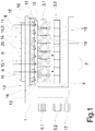
- the Fig. 1 shows a side view
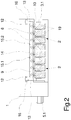
- Fig. 2 a top view
- Fig. 3 schematically a cross-sectional view.
- the following description applies to all figures, insofar as no explicit reference is made to one of the figures.
- the embodiment of the winding machine has in a machine frame 1 a rotatably mounted Spulrevolver 4, are held on the two long projecting Spulspindeln 3.1 and 3.2.
- the winding spindles 3.1 and 3.2 are offset by 180 ° to each other on the winding turret 4 and are coupled to spindle drives 5.1 and 5.2, which are held on the opposite side of the winding turret 4.
- the winding turret 4 is coupled to a turret drive 17.
- winding stations 2 are formed next to each other on the machine frame 1.
- the winding stations 2 are arranged uniformly distributed over the projecting length of the winding spindles 3.1 and 3.2 and each have a head thread guide 11 and arranged below the head thread guide 11 traversing unit 6.
- eight winding stations 2 are arranged side by side.
- the number of winding stations 2 is exemplary and may also include 6, 10, 12 or 16 digits.
- the traversing units 6 are formed in the winding stations 2 by a respective oppositely rotating pair of wings 7, the wing tips a yarn within the winding point 2 along a guide ruler 8 back and forth.
- Such rempligelchangierüen are well known, so that no further description is required for this purpose.
- Fig. 1 to 3 shows the traversing units 6 of the winding stations 2 are held together on a traversing plate 9.
- the traversing plate 9 is supported on a roller carrier 13 which carries a pressure roller 10 arranged between the traversing units 6 and the winding spindles 3.1 and 3.2.
- the roller carrier 13 of the pressure roller 10 is coupled via a pivot bearing 12 to the machine frame 1.
- the pressure roller 10 extends substantially parallel to the winding spindles 3.1 and 3.2 over an entire winding area of the winding points 2.
- the traversing plate 9 is held on the roller carrier 13 via a pivot bearing 16.
- an elongated rough beam 14 extends, which is connected at its ends fixed to the oscillating plate 9.
- damping elements 15.1 and 15.2 are arranged in particular in the central region of the traversing plate 9.
- the damping elements 15.1 and 15.2 are arranged at a distance from each other between the tube beam 14 and the traversing plate 9 and form a support of the traversing plate 9 relative to the tubular beam 14.
- the traversing plate 9 on the underside a plurality of supports 21, with which the traversing plate 9 is supported on the roller carrier 12.
- a winding tube 18 is held on the winding spindles 3.1 and 3.2 for each winding position 2.
- a thread 20 supplied via the head thread guide 11 can be wound into a spool 19 on the circumference of a winding spindle 3.1 or 3.2.
- the winding spindle 3.1 and 3.2 are pivoted on reaching a predetermined coil diameter of the coil 19 of the winding spindle held on a winding spindle by the winding turret 4, so that a yarn change and yarn transfer can take place in the winding stations 2.
- the traversing plate 9 is coupled to the roller carrier 13.
- the roller carrier 13 can be changed via the pivot bearing 12 in its position within the machine frame 1. Such changes occur in particular in the operating state with stationary winding turret 4 in order to be able to carry out, for example, a decrease of full bobbins on the winding spindle held in the change position.
- the traversing units 6 are also changed in the same relation to the pressure roller 10 in its position. This leaves the Distance between the traversing units 6 and the coil surfaces of the coils 19 constant in each operating situation, so that a uniform cross-winding to form the coil 19 is possible.
- the threads 20 are wound in the winding stations 2 parallel to coils 19.
- the threads 20 are fed via the head thread guide 11 to the winding stations 2.
- Each thread 20 is moved back and forth for depositing on a spool 19 by the pair of wings 7 of the traversing units 6 within a traverse stroke and after Generalumschlingung at the periphery of the pressure roller 10 at the periphery of the coil 20.
- the winding spindle 3.1 is driven via the spindle drive 5.1.
- an oscillation excitation takes place with an excitation frequency which changes as a function of the operating rotational speed of the winding spindles 3.1.
- the vibrations are transmitted with the excitation frequency to adjacent modules directly or via the machine frame 1.
- adjacent assemblies first the pressure roller 10 with the roller carrier 13 and the traversing units 6 with the traversing plate 9 are affected. It has been found that excessively high stiffnesses on the oscillating plate 9 adversely affect the displacement of a natural frequency. Basically, a vote between the natural frequencies of the components and the excitation frequency of the winding spindle is required.
- the traversing plate 9 Due to the inventive design of the winding machine, the traversing plate 9 has sufficient rigidity, which is determined essentially by the rigid tube beam 14. The relatively high elasticity in the central region of the traversing plate 9 can be stabilized by the damping elements 15.1 and 15.2. Natural vibrations of the traversing plate 9 can not occur unhindered.
- damping elements 15.1 and 15.2 in the illustrated embodiment of the winding machine at the top of the traversing plate are exemplary. It is essential here that in particular on the oscillating plate no excessive rigidity is generated, which lead to an increase of the natural frequency. As damping elements 15.1 and 15.2 in particular rubber buffers have proven to produce a relatively strong support effect in addition to the damping.
- Fig. 4 is a cross-sectional view of another embodiment of a traversing plate, as for example in the embodiment of Fig. 1 to 3 could be used.
- the traversing plate 9 has in this embodiment, an overall length, which is marked with the code letter L.
- the attached to an upper side of the traversing plate 9 tube bar 14 has a length which is marked with the code letter L R.
- the length L R of the tube bar 14 is dimensioned such that the tube bar covers at least 90% of the total length L of the traversing plate 9.
- the total length L of the traversing plate is in a range of 1.5 m to 2.5 m.
- one or more damping elements can be arranged between the tube bar 14 and the top of the traversing plate 9.
- one damping element 15 is provided at the in Fig. 4 illustrated embodiment.
- the number of damping elements and the type of damping elements is basically arbitrary. It is essential here that a compromise between softness and rigidity of the traversing plate, which is more favorable for the natural frequency of the entire oscillation system, is given.
- the tube beam 14 is connected at its ends via rigid holders 22.1 and 22.2 fixed to the top of the traversing plate.
Landscapes
- Engineering & Computer Science (AREA)
- Textile Engineering (AREA)
- Winding Filamentary Materials (AREA)
- Replacing, Conveying, And Pick-Finding For Filamentary Materials (AREA)
Description
- Die Erfindung betrifft eine Aufspulmaschine zum Aufwickeln mehrerer Fäden gemäß dem Oberbegriff des Anspruchs 1.
- Eine gattungsgemäße Aufspulmaschine zum Aufwickeln mehrerer Fäden zu Spulen ist beispielsweise aus der
DE 10 2006 001 041 A1 bekannt. - Derartige Aufspulmaschinen werden vorzugsweise in Schmelzspinnanlagen zum Aufwickeln mehrerer synthetischer Fäden eingesetzt, wobei die Aufspulmaschine üblicherweise eine Anzahl von Wickelstellen aufweist, die mit einer Anzahl der in einer Spinnposition gleichzeitig gesponnenen Fäden übereinstimmt. Insoweit können mehr als zehn Wickelstellen parallel nebeneinander in einem Maschinengestell der Aufspulmaschine ausgebildet sein. Innerhalb des Maschinengestells der Aufspulmaschine sind üblicherweise mehrere bewegliche Bauteile angebracht, so dass ein Auftreten von Schwingungen der beweglichen Bauteile bei Spulvorgängen an dem festen Maschinengestell mehr oder weniger unvermeidlich ist. So muss eine Spulspindel in Abhängigkeit vom Durchmesser der Spulen vom Anfang bis zum Ende der Aufwicklung einen Drehzahlbereich von ca. 2.000 U/min. bis hin zu 30.000 U/min. durchlaufen. Hierbei müssen im besonderen Maße die kritischen Drehzahlen, die eine ungedämpfte Schwingung der Spulspindel verursachen, vermieden werden, um die einseitige Lagerung einer Spulspindel nicht zu zerstören. Die innerhalb der Aufspulmaschine vorgesehenen Baugruppen stellen ein schwingungsfähiges System dar, das dementsprechend abzustimmen ist.
- Bei der bekannten Aufspulmaschine lässt sich das schwingungsfähige System insbesondere dadurch verändern, indem wahlweise Gestellversteifungen zu oder abgeschaltet werden können, so dass sich die Eigenfrequenz des Schwingungssystems verändert. Somit können Zustände, bei welcher eine Erregerfrequenz mit einer Eigenfrequenz zusammentrifft, vermieden werden.
- Bei einer Vielzahl von Wickelstellen innerhalb eines Maschinengestell wurde nun jedoch festgestellt, dass die teilweise sehr lang auskragende Bauteile eine Neigung aufweisen, besondere Eigenschwingungen zu entwickeln. Diese können insbesondere die Fadenführungen in den Wickelstellen beeinflussen.
- Es ist daher Aufgabe der Erfindung, die gattungsgemäße Aufspulmaschine zum Aufwickeln mehrerer Fäden derart zu verbessern, dass insbesondere die Gestellteile in den Wickelstellen möglichst schwingungsarm gehalten sind.
- Diese Aufgabe wird erfindungsgemäß dadurch gelöst, dass zwischen den Enden des Rohrbalkens zumindest ein Dämpfungselement vorgesehen ist, durch welches die Changierplatte gegenüber dem Rohrbalken abgestützt ist.
- Vorteilhafte Weiterbildungen der Erfindung sind durch die Merkmale und Merkmalskombinationen der Unteransprüche definiert.
- Die erfindungsgemäße Aufspulmaschine zeichnet sich dadurch aus, dass bei sehr lang auskragenden Spulspindeln mit entsprechender Vielzahl von Wickelstellen in jeder der Wickelstelle eine gleichmäßige Fadenführung möglich ist. So können alle Changiereinheiten gemeinsam an einer Changierplatte gehalten werden, ohne dass insbesondere die im mittleren Bereich angeordneten Changiereinheiten durch Eigenschwingungen belastet sind.
- Um die höchste Wirksamkeit zur Stabilisierung der Changierplatte zu erhalten, wird das Dämpfungselement bevorzugt in einem mittleren Bereich der Changierplatte angeordnet.
- Die Steifigkeit der Changierplatte lässt sich dabei bevorzugt durch die Weiterbildung der Erfindung verbessern, bei welcher der Rohrbalken sich im wesentlichen über eine Gesamtlänge der Changierplatte zumindest über 90% der Gesamtlänge der Changierplatte erstreckt.
- Durch derartige Strukturverbesserungen sind Gesamtlängen der Changierplatte im Bereich von 1,5 m bis 2,5 m ohne Schwierigkeiten realisierbar.
- Bei derartig langen Changierplatten ist die Weiterbildung der Erfindung bevorzugt ausgeführt, bei welcher zwischen den Rohrbalken und der Changierplatte mehrere Dämpfungselemente angeordnet sind, die mit Abstand zueinander im mittleren Bereich des Rohrbalkens verteilt gehalten sind.
- Als Dämpfungsmittel wird bevorzugt ein Gummipuffer verwendet, der über einen relativ großen Frequenzbereich eine gleichmäßige Dämpfwirkung erzeugt.
- Zur Verbesserung der Montagemöglichkeiten der Changiereinheiten ist vorgesehen, dass die Changierplatte an den Enden über jeweils ein Schwenklager an dem Maschinengestell gehalten ist.
- Dabei wird das Schwenklager vorzugsweise an einem beweglichen Walzenträger zur Aufnahme einer Andrückwalze ausgebildet, wobei die Changierplatte sich an dem Walzenträger abstützt. Damit ist sichergestellt, dass bei einer Ausweichbewegung einer an den Spulenoberflächen anliegenden Andrückwalze der Abstand zwischen den Changiereinheiten und den Spulenoberflächen konstant bleibt.
- Nachfolgend wird ein Ausführungsbeispiel der erfindungsgemäßen Aufspulmaschine unter Hinweis auf die beigefügten Figuren näher erläutert.
- Es stellen dar:
- Fig. 1
- schematisch eine Seitenansicht des Ausführungsbeispiels der erfindungsgemäßen Aufspulmaschine
- Fig. 2
- schematisch eine Draufsicht des Ausführungsbeispiels aus
Fig. 1 - Fig. 3
- schematisch eine Querschnittsansicht des Ausführungsbeispiels aus
Fig. 1 - Fig. 4
- schematisch eine Draufsicht einer Changierplatte
- In den
Fig. 1-3 ist ein erstes Ausführungsbeispiel der erfindungsgemäßen Aufspulmaschine schematisch in mehreren Ansichten dargestellt. DieFig. 1 zeigt eine Seitenansicht,Fig. 2 eine Draufsicht undFig. 3 schematisch eine Querschnittsansicht. Die nachfolgende Beschreibung gilt für alle Figuren, insoweit kein ausdrücklicher Bezug zu einer der Figuren gemach ist. - Das Ausführungsbeispiel der Aufspulmaschine weist in einem Maschinengestell 1 einen drehbar gelagerten Spulrevolver 4 auf, an dem zwei lang auskragende Spulspindeln 3.1 und 3.2 gehalten sind. Die Spulspindeln 3.1 und 3.2 sind um 180° versetzt zueinander an dem Spulrevolver 4 angeordnet und sind mit Spindelantrieben 5.1 und 5.2 gekoppelt, die auf der gegenüberliegenden Seite des Spulrevolvers 4 gehalten sind. Der Spulrevolver 4 ist mit einem Revolverantrieb 17 gekoppelt.
- Oberhalb der Spulspindel 3.1 und 3.2 sind an dem Maschinengestell 1 mehrere Wickelstellen 2 nebeneinander ausgebildet. Die Wickelstellen 2 sind über die auskragende Länge der Spulspindeln 3.1 und 3.2 gleichmäßig verteilt angeordnet und weisen jeweils einen Kopffadenführer 11 und einen unterhalb der Kopffadenführer 11 angeordnete Changiereinheit 6 auf. In diesem Ausführungsbeispiel sind acht Wickelstellen 2 nebeneinander angeordnet. Die Anzahl der Wickelstellen 2 ist beispielhaft und kann auch 6, 10, 12 oder 16 Stellen enthalten.
- Wie aus der Darstellung in
Fig. 3 hervorgeht, sind die Changiereinheiten 6 in den Wickelstellen 2 durch jeweils ein gegensinnig rotierendes Flügelpaar 7 ausgebildet, deren Flügelspitzen einen Faden innerhalb der Wickelstelle 2 entlang eines Leitlineals 8 hin- und herführen. Derartige Flügelchangiereinheiten sind hinlänglich bekannt, so dass hierzu keine weitere Beschreibung erforderlich ist. - Wie aus den
Fig. 1 bis 3 hervorgeht sind die Changiereinheiten 6 der Wickelstellen 2 gemeinsam an einer Changierplatte 9 gehalten. Die Changierplatte 9 stützt sich an einem Walzenträger 13 ab, der eine zwischen den Changiereinheiten 6 und den Spulspindeln 3.1 und 3.2 angeordnete Andrückwalze 10 trägt. Der Walzenträger 13 der Andrückwalze 10 ist über ein Schwenklager 12 mit dem Maschinengestell 1 gekoppelt. Die Andrückwalze 10 erstreckt sich im wesentlichen parallel zu den Spulspindeln 3.1 und 3.2 über einen gesamten Wickelbereich der Wickelstellen 2. Die Changierplatte 9 ist über ein Schwenklager 16 an dem Walzenträger 13 gehalten. An einer Oberseite der Changierplatte 9 erstreckt sich ein länglicher Rohbalken 14, der mit seinen Enden fest mit der Changierplatte 9 verbunden ist. Zwischen den Enden des Rohrbalkens 14 sind insbesondere im mittleren Bereich der Changierplatte 9 mehrere Dämpfungselemente 15.1 und 15.2 angeordnet. Die Dämpfungselemente 15.1 und 15.2 sind im Abstand zueinander zwischen dem Rohrbalken 14 und der Changierplatte 9 angeordnet und bilden eine Abstützung der Changierplatte 9 gegenüber dem Rohrbalken 14. Wie insbesondere aus derFig. 3 hervorgeht, weist die Changierplatte 9 an der Unterseite mehrere Stützen 21 auf, mit denen sich die Changierplatte 9 an dem Walzenträger 12 abstützt. - Wie aus der Darstellung in
Fig. 1 hervorgeht, sind an den Spulspindeln 3.1 und 3.2 zu jeder Wickelstelle 2 jeweils eine Spulhülse 18 gehalten. So lässt sich ein über die Kopffadenführer 11 zugeführter Faden 20 zu einer Spule 19 am Umfang einer Spulspindel 3.1 oder 3.2 wickeln. Die Spulspindel 3.1 und 3.2 werden bei Erreichen eines vorbestimmten Spulendurchmessers der Spule 19 der an einem Wickelbereich gehaltenen Spulspindel durch den Spulrevolver 4 verschwenkt, so dass ein Fadenwechsel und Fadenübergabe in den Wickelstellen 2 stattfinden kann. - Wie aus der Darstellung in
Fig. 3 hervorgeht, ist die Changierplatte 9 mit dem Walzenträger 13 gekoppelt. Der Walzenträger 13 lässt sich über das Schwenklager 12 in seiner Stellung innerhalb des Maschinengestells 1 verändern. Derartige Veränderungen treten insbesondere im Betriebszustand bei stillstehendem Spulrevolver 4 auf, um beispielsweise eine Abnahme von Vollspulen an der in der Wechselstellung gehaltenen Spulspindel vornehmen zu können. Durch die Kopplung der Changierplatte 9 mit dem Walzenträger 13 werden die Changiereinheiten 6 ebenfalls in gleicher Relation zu der Andrückwalze 10 in ihrer Stellung verändert. Damit bleibt der Abstand zwischen den Changiereinheiten 6 und den Spulenoberflächen der Spulen 19 in jeder Betriebssituation konstant, so dass eine gleichmäßige Kreuzwicklung zur Bildung der Spule 19 möglich ist. - Bei dem in
Fig. 1 bis 3 dargestellten Ausführungsbeispiel der erfindungsgemäßen Aufspulmaschine werden die Fäden 20 in den Wickelstellen 2 parallel zu Spulen 19 gewickelt. Hierzu werden die Fäden 20 über die Kopffadenführer 11 den Wickelstellen 2 zugeführt. Jeder Faden 20 wird zum Ablegen auf eine Spule 19 durch das Flügelpaar 7 der Changiereinheiten 6 innerhalb eines Changierhubes hin- und hergeführt und nach Teilumschlingung am Umfang der Andrückwalze 10 am Umfang der Spule 20 abgelegt. Während des Aufwickelns der Fäden 20 zu Spulen 19 wird die Spulspindel 3.1 über den Spindelantrieb 5.1 angetrieben. Dabei erfolgt eine Schwingungsanregung mit einer Erregerfrequenz, die sich in Abhängigkeit von der Betriebsdrehzahl der Spulspindeln 3.1 ändert. Die Schwingungen werden mit der Erregerfrequenz auf benachbarte Baugruppen unmittelbar oder über das Maschinengestell 1 übertragen. Als benachbarte Baugruppen ist zunächst die Andrückwalze 10 mit dem Walzenträger 13 und die Changiereinheiten 6 mit der Changierplatte 9 betroffen. Dabei hat sich herausgestellt, dass zu hohe Steifigkeiten an der Changierplatte 9 sich ungünstig auf die Verschiebung einer Eigenfrequenz auswirken. Grundsätzlich ist eine Abstimmung zwischen den Eigenfrequenzen der Bauteile und der Erregerfrequenz der Spulspindel erforderlich. Durch die erfindungsgemäße Ausbildung der Aufspulmaschine weist die Changierplatte 9 eine ausreichende Steifigkeit auf, die im wesentlichen durch den starren Rohrbalken 14 bestimmt ist. Die relativ hohe Elastizität im mittleren Bereich der Changierplatte 9 lässt sich dabei durch die Dämpfungselemente 15.1 und 15.2 stabilisieren. Eigenschwingungen der Changierplatte 9 können nicht ungehindert auftreten. - Die Ausgestaltung und Anbringung der Dämpfungselemente 15.1 und 15.2 in dem dargestellten Ausführungsbeispiel der Aufspulmaschine an der Oberseite der Changierplatte sind beispielhaft. Wesentlich hierbei ist, dass insbesondere an der Changierplatte keine überhöhte Steifigkeit erzeugt wird, die zu einer Anhebung der Eigenfrequenz führen. Als Dämpfungselemente 15.1 und 15.2 haben sich insbesondere Gummipuffer bewährt, die neben der Dämpfung eine relativ starke Stützwirkung erzeugen.
- In
Fig. 4 ist eine Querschnittsansicht eines weiteren Ausführungsbeispiels einer Changierplatte, wie sie beispielsweise in dem Ausführungsbeispiel nachFig. 1 bis 3 eingesetzt werden könnte. Die Changierplatte 9 weist in diesem Ausführungsbeispiel eine Gesamtlänge auf, die mit dem Kennbuchstaben L gekennzeichnet ist. Der an einer Oberseite der Changierplatte 9 befestigte Rohrbalken 14 weist eine Länge auf, die mit dem Kennbuchstaben LR gekennzeichnet ist. Die Länge LR des Rohrbalkens 14 ist derart bemessen, dass der Rohrbalken zumindest 90% der Gesamtlänge L der Changierplatte 9 überdeckt. In Abhängigkeit von der Anzahl der Wickelstellen 2 liegt die Gesamtlänge L der Changierplatte dabei in einem Bereich von 1,5 m bis 2,5 m. Je nach Länge der Changierplatte 9 können dabei ein oder mehrere Dämpfungselemente zwischen dem Rohrbalken 14 und der Oberseite der Changierplatte 9 angeordnet sein. Bei dem inFig. 4 dargestellten Ausführungsbeispiel ist nur ein Dämpfungselement 15 vorgesehen. Die Anzahl der Dämpfungselemente sowie die Art der Dämpfungselemente ist grundsätzlich beliebig. Wesentlich hierbei ist, dass ein für die Eigenfrequenz des gesamten Schwingungssystems günstiger Kompromiss zwischen Weichheit und Steifigkeit der Changierplatte gegeben ist. - Der Rohrbalken 14 ist mit seinen Enden über starre Halter 22.1 und 22.2 fest mit der Oberseite der Changierplatte verbunden.
-
- 1
- Maschinengestell
- 2
- Wickelstellen
- 3.1,3.2
- Spulspindel
- 4
- Spulrevolver
- 5.1,5.2
- Spindelantriebe
- 6
- Changiereinheiten
- 7
- Flügelpaar
- 8
- Leitlineal
- 9
- Changierplatte
- 10
- Andrückwalze
- 11
- Kopffadenführer
- 12
- Schwenklager Walzenträger
- 13
- Walzenträger
- 14
- Rohrbalken
- 15.1, 15.2
- Dämpfungselement
- 16
- Schwenklager Changierplatte
- 17
- Revolverantrieb
- 18
- Spulhülse
- 19
- Spule
- 20
- Faden
- 21
- Stütze
- 22.1,22.2
- Halter
Claims (8)
- Aufspulmaschine zum Aufwickeln mehrerer Fäden zu mehreren Spulen, mit zumindest einer Spulspindel (3.1, 3.2) und mehreren entlang der Spulspindel (3.1, 3.2) angeordneten Wickelstellen (2), wobei jede der Wickelstellen (2) eine von mehreren Changiereinheiten (6) zum Hin- und Herführen der Fäden aufweist, wobei die Changiereinheiten (6) nebeneinander durch eine Changierplatte (9) in einem Maschinengestell (1) gehalten sind und wobei die Changierplatte (9) an einer Seite einen mit Abstand angeordneten Rohrbalken (14) aufweist, der an seinen Enden fest mit der Changierplatte (9) verbunden ist, dadurch gekennzeichnet, dass zwischen den Enden des Rohrbalkens (14) an der Seite der Changierplatte (9) zumindest ein Dämpfungselement (15) vorgesehen ist, durch welches die Changierplatte (9) gegenüber dem Rohrbalken (14) abgestützt ist.
- Aufspulmaschine nach Anspruch 1, dadurch gekennzeichnet, dass das Dämpfungselement (15) in einem mittleren Bereich der Changierplatte (9) angeordnet ist.
- Aufspulmaschine nach Anspruch 1 oder 2, dadurch gekennzeichnet, dass der Rohrbalken (14) sich im Wesentlichen über eine Gesamtlänge (L) der Changierplatte (9) zumindest über 90% der Gesamtlänge (L) der Changierplatte (9) erstreckt.
- Aufspulmaschine nach Anspruch 3, dadurch gekennzeichnet, dass die Gesamtlänge (L) der Changierplatte (9) im Bereich von 1,5 m bis 2,5 m liegt.
- Aufspulmaschine nach einem der Ansprüche 1 bis 4, dadurch gekennzeichnet, dass zwischen dem Rohrbalken (14) und der Changierplatte (9) mehrere Dämpfungselemente (15.1, 15.2) angeordnet sind, die mit Abstand zueinander im mittleren Bereich des Rohrbalkens (14) verteilt gehalten sind.
- Aufspulmaschine nach einem der Ansprüche 1 bis 5, dadurch gekennzeichnet, dass das Dämpfungsmittel (15) durch einen Gummipuffer gebildet ist.
- Aufspulmaschine nach einem der Ansprüche 1 bis 6, dadurch gekennzeichnet, dass die Changierplatte (9) an den Enden über jeweils ein Schwenklager (16) an dem Maschinengestell (1) gehalten ist.
- Aufspulmaschine nach Anspruch 7, dadurch gekennzeichnet, dass die Schwenklager (16) an einem beweglichen Walzenträger (13) zur Aufnahme einer Andrückwalze (10) ausgebildet ist, wobei die Changierplatte (9) sich an dem Walzenträger (13) abstützt.
Applications Claiming Priority (2)
| Application Number | Priority Date | Filing Date | Title |
|---|---|---|---|
| DE102013008825.9A DE102013008825A1 (de) | 2013-05-24 | 2013-05-24 | Aufspulmaschine |
| PCT/EP2014/059428 WO2014187677A1 (de) | 2013-05-24 | 2014-05-08 | Aufspulmaschine |
Publications (2)
| Publication Number | Publication Date |
|---|---|
| EP3003937A1 EP3003937A1 (de) | 2016-04-13 |
| EP3003937B1 true EP3003937B1 (de) | 2017-07-05 |
Family
ID=50680046
Family Applications (1)
| Application Number | Title | Priority Date | Filing Date |
|---|---|---|---|
| EP14722218.6A Active EP3003937B1 (de) | 2013-05-24 | 2014-05-08 | Aufspulmaschine |
Country Status (6)
| Country | Link |
|---|---|
| US (1) | US20160101961A1 (de) |
| EP (1) | EP3003937B1 (de) |
| JP (1) | JP6391675B2 (de) |
| CN (1) | CN105377734B (de) |
| DE (1) | DE102013008825A1 (de) |
| WO (1) | WO2014187677A1 (de) |
Cited By (1)
| Publication number | Priority date | Publication date | Assignee | Title |
|---|---|---|---|---|
| DE102020002770A1 (de) | 2020-05-09 | 2021-11-11 | Oerlikon Textile Gmbh & Co. Kg | Verfahren zum Handhaben einer Fadenspule sowie Hilfseinrichtung zum Handhaben einer Fadenspule |
Families Citing this family (14)
| Publication number | Priority date | Publication date | Assignee | Title |
|---|---|---|---|---|
| JP6781011B2 (ja) * | 2016-11-01 | 2020-11-04 | Tmtマシナリー株式会社 | トラバース装置及び糸巻取装置 |
| JP6761731B2 (ja) * | 2016-11-01 | 2020-09-30 | Tmtマシナリー株式会社 | バランス修正方法及び回転部材 |
| CN110506020B (zh) * | 2017-04-07 | 2021-06-15 | 欧瑞康纺织有限及两合公司 | 卷绕机 |
| DE102017004866A1 (de) * | 2017-05-19 | 2018-11-22 | Oerlikon Textile Gmbh & Co. Kg | Verfahren zum Bedienen einer Aufspulmaschine sowie eine Aufspulmaschine |
| JP6935243B2 (ja) * | 2017-06-21 | 2021-09-15 | Tmtマシナリー株式会社 | 糸巻取機 |
| DE102017006865A1 (de) * | 2017-07-19 | 2019-01-24 | Oerlikon Textile Gmbh & Co. Kg | Aufspulmaschine |
| CN108178015B (zh) * | 2017-12-07 | 2020-06-02 | 丁年生 | 一种用于色纺纱线的送纱卷纱装置及其使用方法 |
| WO2020126724A1 (de) * | 2018-12-19 | 2020-06-25 | Oerlikon Textile Gmbh & Co. Kg | Aufspulmaschine |
| CN111977452B (zh) * | 2020-07-22 | 2022-03-15 | 杭州华龙纺织机械有限公司 | 一种复摇机 |
| DE102020004592A1 (de) * | 2020-07-29 | 2022-02-03 | Oerlikon Textile Gmbh & Co. Kg | Aufspulmaschine |
| DE102021002456A1 (de) * | 2021-05-08 | 2022-11-10 | Oerlikon Textile Gmbh & Co. Kg | Aufspulmaschine |
| DE102022116443B3 (de) * | 2021-07-14 | 2022-10-27 | Oerlikon Textile Gmbh & Co. Kg | Aufspulmaschine |
| CN116812612B (zh) * | 2023-06-14 | 2026-02-10 | 桐昆集团浙江恒腾差别化纤维有限公司 | 一种卷绕机横动箱加装防震装置 |
| JP2025096163A (ja) * | 2023-12-15 | 2025-06-26 | Tmtマシナリー株式会社 | 長尺部材の振動抑制システム及びボビンホルダ |
Family Cites Families (8)
| Publication number | Priority date | Publication date | Assignee | Title |
|---|---|---|---|---|
| US5100072A (en) * | 1990-06-06 | 1992-03-31 | Barmag Ag | Yarn winding apparatus and method |
| JP2505140B2 (ja) * | 1991-12-05 | 1996-06-05 | 村田機械株式会社 | 紡糸巻取機 |
| US5915508A (en) * | 1994-04-18 | 1999-06-29 | Minnesota Mining And Manufacturing Company | Tuned mass damper |
| DE10060593A1 (de) * | 1999-12-24 | 2001-07-05 | Barmag Barmer Maschf | Aufspulmaschine |
| DE102005044804A1 (de) * | 2004-09-30 | 2006-04-06 | Saurer Gmbh & Co. Kg | Aufspulmaschine |
| CN1810618A (zh) * | 2005-01-28 | 2006-08-02 | 苏拉有限及两合公司 | 卷绕多股长丝的方法和装置 |
| DE102006001041A1 (de) | 2005-01-28 | 2006-08-03 | Saurer Gmbh & Co. Kg | Verfahren und Vorrichtung zum Aufwickeln mehrerer Fäden |
| DE102011114025A1 (de) * | 2011-09-21 | 2013-03-21 | Oerlikon Textile Gmbh & Co. Kg | Aufspulmaschine |
-
2013
- 2013-05-24 DE DE102013008825.9A patent/DE102013008825A1/de not_active Withdrawn
-
2014
- 2014-05-08 CN CN201480029017.8A patent/CN105377734B/zh active Active
- 2014-05-08 EP EP14722218.6A patent/EP3003937B1/de active Active
- 2014-05-08 US US14/892,676 patent/US20160101961A1/en not_active Abandoned
- 2014-05-08 JP JP2016514324A patent/JP6391675B2/ja active Active
- 2014-05-08 WO PCT/EP2014/059428 patent/WO2014187677A1/de not_active Ceased
Non-Patent Citations (1)
| Title |
|---|
| None * |
Cited By (2)
| Publication number | Priority date | Publication date | Assignee | Title |
|---|---|---|---|---|
| DE102020002770A1 (de) | 2020-05-09 | 2021-11-11 | Oerlikon Textile Gmbh & Co. Kg | Verfahren zum Handhaben einer Fadenspule sowie Hilfseinrichtung zum Handhaben einer Fadenspule |
| WO2021228622A1 (de) | 2020-05-09 | 2021-11-18 | Oerlikon Textile Gmbh & Co. Kg | Verfahren zum handhaben einer fadenspule sowie hilfseinrichtung zum handhaben einer fadenspule |
Also Published As
| Publication number | Publication date |
|---|---|
| US20160101961A1 (en) | 2016-04-14 |
| CN105377734A (zh) | 2016-03-02 |
| JP2016519032A (ja) | 2016-06-30 |
| JP6391675B2 (ja) | 2018-09-19 |
| EP3003937A1 (de) | 2016-04-13 |
| DE102013008825A1 (de) | 2014-11-27 |
| WO2014187677A1 (de) | 2014-11-27 |
| CN105377734B (zh) | 2017-07-21 |
Similar Documents
| Publication | Publication Date | Title |
|---|---|---|
| WO2014187677A1 (de) | Aufspulmaschine | |
| DE102009035393A1 (de) | Spulenwechseleinrichtung für eine Vorspinnmaschine | |
| WO2018036916A1 (de) | Verfahren zur steuerung einer aufspulmaschine und aufspulmaschine | |
| DE102011114312A1 (de) | Vorrichtung zum Aufwickeln synthetischer Fäden sowie Aufspulmaschine | |
| EP2251291A2 (de) | Fadenspeicher für eine Arbeitsstelle einer Offenend-Spinnmaschine | |
| DE102015002963A1 (de) | Aufspulmaschine | |
| WO2010124730A1 (de) | Aufspulmaschine | |
| EP3206846B1 (de) | Vorrichtung sowie verfahren zum bereitstellen von verstärkungsstrangschlaufen | |
| DE102007041696B4 (de) | Changiereinrichtung | |
| WO2019025262A1 (de) | Vorrichtung zum aufwickeln eines fadens zu spulen | |
| EP0165444B1 (de) | Antriebsvorrichtung und Verfahren für eine Paraffiniereinrichtung | |
| EP2251292A1 (de) | Paraffiniereinrichtung für eine Kreuzspulen herstellende Textilmaschine | |
| EP1728748A1 (de) | Fadenchangiervorrichtung für eine Spuleinrichtung einer Kreuzspulen herstellenden Textilmaschine | |
| EP3483313B1 (de) | Ringspinnmaschine mit beweglich gelagerter spindelbank | |
| DE102006001041A1 (de) | Verfahren und Vorrichtung zum Aufwickeln mehrerer Fäden | |
| EP3257979B1 (de) | Fadenklemmvorrichtung | |
| DE102007031151A1 (de) | Luftspinnmaschine | |
| EP1730064B1 (de) | Aufspulvorrichtung | |
| DE102004016257A1 (de) | Verfahren zum Aufwickeln eines Fadens sowie eine Aufspulmaschine | |
| DE102018132951A1 (de) | Ringspinnmaschine mit Streckwerken | |
| EP1727758B1 (de) | Verfahren und vorrichtung zum aufwickeln mehrerer fäden | |
| DE102016014977A1 (de) | Aufspulmaschine | |
| EP2948399B1 (de) | Aufspulmaschine | |
| DE102016121746A1 (de) | Fadenumlenkrolle für einen im Bereich des Fadenchangierdreieckes einer Arbeitsstelle einer Kreuzspulen herstellenden Textilmaschine angeordneten mechanischen Fadenspeicher | |
| DE102017000607A1 (de) | Vorrichtung zum Abziehen, Verstrecken und Aufwickeln einer synthetischen Fadenschar |
Legal Events
| Date | Code | Title | Description |
|---|---|---|---|
| PUAI | Public reference made under article 153(3) epc to a published international application that has entered the european phase |
Free format text: ORIGINAL CODE: 0009012 |
|
| 17P | Request for examination filed |
Effective date: 20151216 |
|
| AK | Designated contracting states |
Kind code of ref document: A1 Designated state(s): AL AT BE BG CH CY CZ DE DK EE ES FI FR GB GR HR HU IE IS IT LI LT LU LV MC MK MT NL NO PL PT RO RS SE SI SK SM TR |
|
| AX | Request for extension of the european patent |
Extension state: BA ME |
|
| DAX | Request for extension of the european patent (deleted) | ||
| GRAP | Despatch of communication of intention to grant a patent |
Free format text: ORIGINAL CODE: EPIDOSNIGR1 |
|
| INTG | Intention to grant announced |
Effective date: 20170223 |
|
| GRAS | Grant fee paid |
Free format text: ORIGINAL CODE: EPIDOSNIGR3 |
|
| GRAA | (expected) grant |
Free format text: ORIGINAL CODE: 0009210 |
|
| AK | Designated contracting states |
Kind code of ref document: B1 Designated state(s): AL AT BE BG CH CY CZ DE DK EE ES FI FR GB GR HR HU IE IS IT LI LT LU LV MC MK MT NL NO PL PT RO RS SE SI SK SM TR |
|
| REG | Reference to a national code |
Ref country code: GB Ref legal event code: FG4D Free format text: NOT ENGLISH |
|
| REG | Reference to a national code |
Ref country code: CH Ref legal event code: EP |
|
| REG | Reference to a national code |
Ref country code: AT Ref legal event code: REF Ref document number: 906451 Country of ref document: AT Kind code of ref document: T Effective date: 20170715 |
|
| REG | Reference to a national code |
Ref country code: IE Ref legal event code: FG4D Free format text: LANGUAGE OF EP DOCUMENT: GERMAN |
|
| REG | Reference to a national code |
Ref country code: DE Ref legal event code: R096 Ref document number: 502014004488 Country of ref document: DE |
|
| REG | Reference to a national code |
Ref country code: NL Ref legal event code: MP Effective date: 20170705 |
|
| REG | Reference to a national code |
Ref country code: LT Ref legal event code: MG4D |
|
| PG25 | Lapsed in a contracting state [announced via postgrant information from national office to epo] |
Ref country code: SE Free format text: LAPSE BECAUSE OF FAILURE TO SUBMIT A TRANSLATION OF THE DESCRIPTION OR TO PAY THE FEE WITHIN THE PRESCRIBED TIME-LIMIT Effective date: 20170705 Ref country code: FI Free format text: LAPSE BECAUSE OF FAILURE TO SUBMIT A TRANSLATION OF THE DESCRIPTION OR TO PAY THE FEE WITHIN THE PRESCRIBED TIME-LIMIT Effective date: 20170705 Ref country code: HR Free format text: LAPSE BECAUSE OF FAILURE TO SUBMIT A TRANSLATION OF THE DESCRIPTION OR TO PAY THE FEE WITHIN THE PRESCRIBED TIME-LIMIT Effective date: 20170705 Ref country code: LT Free format text: LAPSE BECAUSE OF FAILURE TO SUBMIT A TRANSLATION OF THE DESCRIPTION OR TO PAY THE FEE WITHIN THE PRESCRIBED TIME-LIMIT Effective date: 20170705 Ref country code: NO Free format text: LAPSE BECAUSE OF FAILURE TO SUBMIT A TRANSLATION OF THE DESCRIPTION OR TO PAY THE FEE WITHIN THE PRESCRIBED TIME-LIMIT Effective date: 20171005 Ref country code: NL Free format text: LAPSE BECAUSE OF FAILURE TO SUBMIT A TRANSLATION OF THE DESCRIPTION OR TO PAY THE FEE WITHIN THE PRESCRIBED TIME-LIMIT Effective date: 20170705 |
|
| PG25 | Lapsed in a contracting state [announced via postgrant information from national office to epo] |
Ref country code: PL Free format text: LAPSE BECAUSE OF FAILURE TO SUBMIT A TRANSLATION OF THE DESCRIPTION OR TO PAY THE FEE WITHIN THE PRESCRIBED TIME-LIMIT Effective date: 20170705 Ref country code: RS Free format text: LAPSE BECAUSE OF FAILURE TO SUBMIT A TRANSLATION OF THE DESCRIPTION OR TO PAY THE FEE WITHIN THE PRESCRIBED TIME-LIMIT Effective date: 20170705 Ref country code: BG Free format text: LAPSE BECAUSE OF FAILURE TO SUBMIT A TRANSLATION OF THE DESCRIPTION OR TO PAY THE FEE WITHIN THE PRESCRIBED TIME-LIMIT Effective date: 20171005 Ref country code: GR Free format text: LAPSE BECAUSE OF FAILURE TO SUBMIT A TRANSLATION OF THE DESCRIPTION OR TO PAY THE FEE WITHIN THE PRESCRIBED TIME-LIMIT Effective date: 20171006 Ref country code: IS Free format text: LAPSE BECAUSE OF FAILURE TO SUBMIT A TRANSLATION OF THE DESCRIPTION OR TO PAY THE FEE WITHIN THE PRESCRIBED TIME-LIMIT Effective date: 20171105 Ref country code: ES Free format text: LAPSE BECAUSE OF FAILURE TO SUBMIT A TRANSLATION OF THE DESCRIPTION OR TO PAY THE FEE WITHIN THE PRESCRIBED TIME-LIMIT Effective date: 20170705 Ref country code: LV Free format text: LAPSE BECAUSE OF FAILURE TO SUBMIT A TRANSLATION OF THE DESCRIPTION OR TO PAY THE FEE WITHIN THE PRESCRIBED TIME-LIMIT Effective date: 20170705 |
|
| REG | Reference to a national code |
Ref country code: DE Ref legal event code: R097 Ref document number: 502014004488 Country of ref document: DE |
|
| PG25 | Lapsed in a contracting state [announced via postgrant information from national office to epo] |
Ref country code: RO Free format text: LAPSE BECAUSE OF FAILURE TO SUBMIT A TRANSLATION OF THE DESCRIPTION OR TO PAY THE FEE WITHIN THE PRESCRIBED TIME-LIMIT Effective date: 20170705 Ref country code: CZ Free format text: LAPSE BECAUSE OF FAILURE TO SUBMIT A TRANSLATION OF THE DESCRIPTION OR TO PAY THE FEE WITHIN THE PRESCRIBED TIME-LIMIT Effective date: 20170705 Ref country code: DK Free format text: LAPSE BECAUSE OF FAILURE TO SUBMIT A TRANSLATION OF THE DESCRIPTION OR TO PAY THE FEE WITHIN THE PRESCRIBED TIME-LIMIT Effective date: 20170705 |
|
| PLBE | No opposition filed within time limit |
Free format text: ORIGINAL CODE: 0009261 |
|
| STAA | Information on the status of an ep patent application or granted ep patent |
Free format text: STATUS: NO OPPOSITION FILED WITHIN TIME LIMIT |
|
| PG25 | Lapsed in a contracting state [announced via postgrant information from national office to epo] |
Ref country code: SK Free format text: LAPSE BECAUSE OF FAILURE TO SUBMIT A TRANSLATION OF THE DESCRIPTION OR TO PAY THE FEE WITHIN THE PRESCRIBED TIME-LIMIT Effective date: 20170705 Ref country code: SM Free format text: LAPSE BECAUSE OF FAILURE TO SUBMIT A TRANSLATION OF THE DESCRIPTION OR TO PAY THE FEE WITHIN THE PRESCRIBED TIME-LIMIT Effective date: 20170705 Ref country code: EE Free format text: LAPSE BECAUSE OF FAILURE TO SUBMIT A TRANSLATION OF THE DESCRIPTION OR TO PAY THE FEE WITHIN THE PRESCRIBED TIME-LIMIT Effective date: 20170705 |
|
| 26N | No opposition filed |
Effective date: 20180406 |
|
| PG25 | Lapsed in a contracting state [announced via postgrant information from national office to epo] |
Ref country code: SI Free format text: LAPSE BECAUSE OF FAILURE TO SUBMIT A TRANSLATION OF THE DESCRIPTION OR TO PAY THE FEE WITHIN THE PRESCRIBED TIME-LIMIT Effective date: 20170705 |
|
| PG25 | Lapsed in a contracting state [announced via postgrant information from national office to epo] |
Ref country code: MT Free format text: LAPSE BECAUSE OF FAILURE TO SUBMIT A TRANSLATION OF THE DESCRIPTION OR TO PAY THE FEE WITHIN THE PRESCRIBED TIME-LIMIT Effective date: 20170705 |
|
| GBPC | Gb: european patent ceased through non-payment of renewal fee |
Effective date: 20180508 |
|
| PG25 | Lapsed in a contracting state [announced via postgrant information from national office to epo] |
Ref country code: MC Free format text: LAPSE BECAUSE OF FAILURE TO SUBMIT A TRANSLATION OF THE DESCRIPTION OR TO PAY THE FEE WITHIN THE PRESCRIBED TIME-LIMIT Effective date: 20170705 |
|
| REG | Reference to a national code |
Ref country code: IE Ref legal event code: MM4A |
|
| PG25 | Lapsed in a contracting state [announced via postgrant information from national office to epo] |
Ref country code: LU Free format text: LAPSE BECAUSE OF NON-PAYMENT OF DUE FEES Effective date: 20180508 |
|
| PG25 | Lapsed in a contracting state [announced via postgrant information from national office to epo] |
Ref country code: FR Free format text: LAPSE BECAUSE OF NON-PAYMENT OF DUE FEES Effective date: 20180531 Ref country code: IE Free format text: LAPSE BECAUSE OF NON-PAYMENT OF DUE FEES Effective date: 20180508 Ref country code: GB Free format text: LAPSE BECAUSE OF NON-PAYMENT OF DUE FEES Effective date: 20180508 |
|
| PGFP | Annual fee paid to national office [announced via postgrant information from national office to epo] |
Ref country code: BE Payment date: 20190520 Year of fee payment: 6 |
|
| PGFP | Annual fee paid to national office [announced via postgrant information from national office to epo] |
Ref country code: CH Payment date: 20190524 Year of fee payment: 6 |
|
| PG25 | Lapsed in a contracting state [announced via postgrant information from national office to epo] |
Ref country code: TR Free format text: LAPSE BECAUSE OF FAILURE TO SUBMIT A TRANSLATION OF THE DESCRIPTION OR TO PAY THE FEE WITHIN THE PRESCRIBED TIME-LIMIT Effective date: 20170705 |
|
| PG25 | Lapsed in a contracting state [announced via postgrant information from national office to epo] |
Ref country code: PT Free format text: LAPSE BECAUSE OF FAILURE TO SUBMIT A TRANSLATION OF THE DESCRIPTION OR TO PAY THE FEE WITHIN THE PRESCRIBED TIME-LIMIT Effective date: 20170705 |
|
| PG25 | Lapsed in a contracting state [announced via postgrant information from national office to epo] |
Ref country code: HU Free format text: LAPSE BECAUSE OF FAILURE TO SUBMIT A TRANSLATION OF THE DESCRIPTION OR TO PAY THE FEE WITHIN THE PRESCRIBED TIME-LIMIT; INVALID AB INITIO Effective date: 20140508 Ref country code: CY Free format text: LAPSE BECAUSE OF FAILURE TO SUBMIT A TRANSLATION OF THE DESCRIPTION OR TO PAY THE FEE WITHIN THE PRESCRIBED TIME-LIMIT Effective date: 20170705 Ref country code: MK Free format text: LAPSE BECAUSE OF NON-PAYMENT OF DUE FEES Effective date: 20170705 |
|
| PG25 | Lapsed in a contracting state [announced via postgrant information from national office to epo] |
Ref country code: AL Free format text: LAPSE BECAUSE OF FAILURE TO SUBMIT A TRANSLATION OF THE DESCRIPTION OR TO PAY THE FEE WITHIN THE PRESCRIBED TIME-LIMIT Effective date: 20170705 |
|
| REG | Reference to a national code |
Ref country code: AT Ref legal event code: MM01 Ref document number: 906451 Country of ref document: AT Kind code of ref document: T Effective date: 20190508 |
|
| PG25 | Lapsed in a contracting state [announced via postgrant information from national office to epo] |
Ref country code: AT Free format text: LAPSE BECAUSE OF NON-PAYMENT OF DUE FEES Effective date: 20190508 |
|
| PG25 | Lapsed in a contracting state [announced via postgrant information from national office to epo] |
Ref country code: LI Free format text: LAPSE BECAUSE OF NON-PAYMENT OF DUE FEES Effective date: 20200531 Ref country code: CH Free format text: LAPSE BECAUSE OF NON-PAYMENT OF DUE FEES Effective date: 20200531 |
|
| REG | Reference to a national code |
Ref country code: BE Ref legal event code: MM Effective date: 20200531 |
|
| PG25 | Lapsed in a contracting state [announced via postgrant information from national office to epo] |
Ref country code: BE Free format text: LAPSE BECAUSE OF NON-PAYMENT OF DUE FEES Effective date: 20200531 |
|
| PGFP | Annual fee paid to national office [announced via postgrant information from national office to epo] |
Ref country code: IT Payment date: 20210527 Year of fee payment: 8 |
|
| PG25 | Lapsed in a contracting state [announced via postgrant information from national office to epo] |
Ref country code: IT Free format text: LAPSE BECAUSE OF NON-PAYMENT OF DUE FEES Effective date: 20220508 |
|
| PGFP | Annual fee paid to national office [announced via postgrant information from national office to epo] |
Ref country code: DE Payment date: 20250521 Year of fee payment: 12 |