EP3000942A1 - Rammgerät und Verfahren zum Einrammen eines Pfahlelementes in den Boden - Google Patents
Rammgerät und Verfahren zum Einrammen eines Pfahlelementes in den Boden Download PDFInfo
- Publication number
- EP3000942A1 EP3000942A1 EP14186393.6A EP14186393A EP3000942A1 EP 3000942 A1 EP3000942 A1 EP 3000942A1 EP 14186393 A EP14186393 A EP 14186393A EP 3000942 A1 EP3000942 A1 EP 3000942A1
- Authority
- EP
- European Patent Office
- Prior art keywords
- pile element
- winch
- auxiliary
- main
- hammer unit
- Prior art date
- Legal status (The legal status is an assumption and is not a legal conclusion. Google has not performed a legal analysis and makes no representation as to the accuracy of the status listed.)
- Granted
Links
Images


Classifications
-
- E—FIXED CONSTRUCTIONS
- E02—HYDRAULIC ENGINEERING; FOUNDATIONS; SOIL SHIFTING
- E02D—FOUNDATIONS; EXCAVATIONS; EMBANKMENTS; UNDERGROUND OR UNDERWATER STRUCTURES
- E02D7/00—Methods or apparatus for placing sheet pile bulkheads, piles, mouldpipes, or other moulds
- E02D7/02—Placing by driving
- E02D7/06—Power-driven drivers
- E02D7/08—Drop drivers with free-falling hammer
-
- E—FIXED CONSTRUCTIONS
- E02—HYDRAULIC ENGINEERING; FOUNDATIONS; SOIL SHIFTING
- E02D—FOUNDATIONS; EXCAVATIONS; EMBANKMENTS; UNDERGROUND OR UNDERWATER STRUCTURES
- E02D7/00—Methods or apparatus for placing sheet pile bulkheads, piles, mouldpipes, or other moulds
- E02D7/02—Placing by driving
- E02D7/06—Power-driven drivers
- E02D7/10—Power-driven drivers with pressure-actuated hammer, i.e. the pressure fluid acting directly on the hammer structure
-
- E—FIXED CONSTRUCTIONS
- E02—HYDRAULIC ENGINEERING; FOUNDATIONS; SOIL SHIFTING
- E02B—HYDRAULIC ENGINEERING
- E02B7/00—Barrages or weirs; Layout, construction, methods of, or devices for, making same
- E02B7/02—Fixed barrages
- E02B7/04—Dams across valleys
- E02B7/08—Wall dams
-
- E—FIXED CONSTRUCTIONS
- E02—HYDRAULIC ENGINEERING; FOUNDATIONS; SOIL SHIFTING
- E02D—FOUNDATIONS; EXCAVATIONS; EMBANKMENTS; UNDERGROUND OR UNDERWATER STRUCTURES
- E02D11/00—Methods or apparatus specially adapted for both placing and removing sheet pile bulkheads, piles, or mould-pipes
-
- E—FIXED CONSTRUCTIONS
- E02—HYDRAULIC ENGINEERING; FOUNDATIONS; SOIL SHIFTING
- E02D—FOUNDATIONS; EXCAVATIONS; EMBANKMENTS; UNDERGROUND OR UNDERWATER STRUCTURES
- E02D13/00—Accessories for placing or removing piles or bulkheads, e.g. noise attenuating chambers
-
- E—FIXED CONSTRUCTIONS
- E02—HYDRAULIC ENGINEERING; FOUNDATIONS; SOIL SHIFTING
- E02D—FOUNDATIONS; EXCAVATIONS; EMBANKMENTS; UNDERGROUND OR UNDERWATER STRUCTURES
- E02D7/00—Methods or apparatus for placing sheet pile bulkheads, piles, mouldpipes, or other moulds
- E02D7/02—Placing by driving
- E02D7/06—Power-driven drivers
- E02D7/12—Drivers with explosion chambers
- E02D7/125—Diesel drivers
-
- E—FIXED CONSTRUCTIONS
- E21—EARTH OR ROCK DRILLING; MINING
- E21B—EARTH OR ROCK DRILLING; OBTAINING OIL, GAS, WATER, SOLUBLE OR MELTABLE MATERIALS OR A SLURRY OF MINERALS FROM WELLS
- E21B15/00—Supports for the drilling machine, e.g. derricks or masts
-
- E—FIXED CONSTRUCTIONS
- E21—EARTH OR ROCK DRILLING; MINING
- E21B—EARTH OR ROCK DRILLING; OBTAINING OIL, GAS, WATER, SOLUBLE OR MELTABLE MATERIALS OR A SLURRY OF MINERALS FROM WELLS
- E21B7/00—Special methods or apparatus for drilling
- E21B7/02—Drilling rigs characterised by means for land transport with their own drive, e.g. skid mounting or wheel mounting
-
- E—FIXED CONSTRUCTIONS
- E02—HYDRAULIC ENGINEERING; FOUNDATIONS; SOIL SHIFTING
- E02D—FOUNDATIONS; EXCAVATIONS; EMBANKMENTS; UNDERGROUND OR UNDERWATER STRUCTURES
- E02D7/00—Methods or apparatus for placing sheet pile bulkheads, piles, mouldpipes, or other moulds
- E02D7/02—Placing by driving
- E02D7/06—Power-driven drivers
Definitions
- the invention relates to a pile driver for driving a pile element into the ground with a mast, a driven hammer unit, which is movably mounted along the mast and has a driving hood in a lower region, which is designed to receive a head region of the pile element to be excavated, a main winch Main rope, which is connected to the hammer unit for moving the hammer unit along the mast, and an auxiliary winch with auxiliary rope, which is guided over the mast and is connectable to a prominent pile element, said means of the auxiliary winch Conceptrammende the pile element from a lying position in an approximately vertical ramming position can be erected, wherein the head portion of the pile element is received in the driving hood of the hammer unit, according to the preamble of claim 1.
- the invention further relates to a method for driving a pile element into the ground, wherein a head region of the pile element is arranged in a driving hood on a lower side of a driven hammer unit, which is moved by a main winch with a main rope along a mast and the pile element in an approximately vertical Rammposition rammed into the ground, wherein the pile element is set by means of an auxiliary winch with auxiliary rope from a lying position in the approximately vertical ramming position, in which the head portion of the pile element is received in the ramming hood of the hammer unit, according to the preamble of claim.
- Such piling devices and such methods are used in foundation measures, in which pile elements are driven into a relatively soft soil.
- the pile driver on a hammer unit which depends on the drive may be a so-called diesel hammer or a hydraulic hammer.
- the hammer unit generates impact pulses which are applied to the head area of a pile element so that the pile element is driven into the ground.
- the pile elements which are usually formed of steel or concrete, must first be placed from a typically lying transort or storage position in the vertical operating or piling position.
- an auxiliary winch with an auxiliary rope located on the mast of the piling an auxiliary winch with an auxiliary rope, the free end is mounted in an upper region of the pile element, so that the pile element can be placed from the lying position with the auxiliary winch in the vertical ramming position.
- the invention has for its object to provide a piling device and a method for driving in a pile element, with which an efficient and very safe operation is possible.
- the piling device is characterized in that a control device for simultaneously controlling the main winch and the auxiliary winch is provided and that when setting up the pile element to be eingurammenden the main winch and the auxiliary winch are controlled by the controller, so that the hammer unit from a lower initial position on the mast the main winch is movable and the head portion of the pile element rests during deployment by means of the auxiliary winch on the Rammhaube with a predeterminable pressure force.
- a first aspect of the invention consists in that, when the pile element is set up from a lying position into the ramming position, a head region of the pile element rests in a defined manner on the ramming hood of the hammer unit.
- the pile element is always in contact with the ground on the one hand and on the other hand with the Rammhaube. Through this multiple contact the risk of swinging the pile element during erection is effectively prevented.
- the predeterminable pressure force is not a single force value, but preferably a force value range which is predetermined by a lower minimum value and an upper maximum value. The minimum value must be so large that the Pile element safely remains on the Rammhaube during deployment, while the maximum value is selected so that the driving force is not damaged by the pressure force.
- control device has an input device for adjusting the pressing force.
- the input device may expediently be a simple controller or a potentiometer with which an operator controls the auxiliary winch and / or the main winch so that a desired pressure force of the pile element is effected on the driving hood.
- default buttons can also be preset with standard pressure force values.
- the winches can be driven arbitrarily.
- a particularly expedient embodiment of the invention results from the fact that the main winch and the auxiliary winch each have a hydraulic motor and that the supply of hydraulic fluid in one of the hydraulic motors or in both hydraulic motors for adjusting the pressing force is controlled by the control device.
- hydraulic motors are particularly compact and enable efficient force application.
- the control by changing the supply of hydraulic fluid to a hydraulic motor, such as by changing the flow rate or the hydraulic pressure, on the other hand allow fast and accurate control of the winch drives.
- a hydraulic pressure control valve is arranged, which can be actuated via the control device.
- the hydraulic pressure control valve is only in the supply to a hydraulic motor, in particular to the hydraulic motor of the main winch.
- the auxiliary winch with a greater rotational speed and / or tensile force is operated as the rotational speed or tensile force of the main winch.
- This ensures that the pile element always rests reliably with the desired pressure force on the Rammhaube the hammer unit.
- the auxiliary winch is to be controlled or adjusted so that a tip of the pile element is supported on the ground.
- control device has a switch with which can be switched between a single control of main winch and auxiliary winch and a common automatic control.
- the control device may have a portable manual unit, on which the input device and the switch are arranged. It is thus possible for an operator to continue to operate and adjust the main winch and thus the hammer unit and the auxiliary winch and thus the pile element independently of each other. However, for a safe and reliable deployment, the operator may switch to the automatic control so that after an initial adjustment and application of the head portion of the pile element to the ram, automatic deployment and threading of the pile element to the hammer unit is performed.
- the method according to the invention for driving in a pile element into the ground is characterized in that the main winch and the auxiliary winch are simultaneously controlled automatically by a control device when setting up the pile element to be pierced, so that the head area of the pile element rests with a predeterminable pressure force during the erection of the pile cap ,
- the method can be carried out in particular by the piling device described above. It can be achieved with the method according to the invention, the advantages described above.
- a fixed predetermined pressure force can be stored in the control device. It is preferred according to a variant of the invention that the pressing force is adjusted by means of the control device. This can be done via a controller, in particular a potentiometer, or via a numeric input field.
- the pressure force can be adapted to different sizes and weights of the pile element.
- an advantageous embodiment of the invention is that for adjusting the pressing force, the auxiliary winch operated and the pile element is pressed against the driving hood, while the main winch is stationary and the hammer unit is in a lower initial position on the mast and that subsequently by the control device Main winch and the auxiliary winch are operated, the hammer unit is moved from the lower initial position along the mast in an upper ramming position, while the pile element is pressed continuously against the driving hood.
- the adjustment of the pressure force can thus be done in practice by the operator by a simple adjustment and pressing the pile element to the driving hood, while the hammer unit is in a lower initial position on the mast.
- a measuring device in particular a sensor device, can be provided on the winch or the ram hood, with which the instantaneous contact pressure force is displayed.
- a measuring device is not absolutely necessary.
- the hammer unit is controlled by the main winch moves upward, while the pile element by the synchronously controlled auxiliary winch continues to push the pile element against the upwardly moving hammer unit until the pile element the reached vertical end position and threaded into the cylindrical receiving space of the cup-shaped Rammhaube.
- the drive of the two winches is then stopped.
- the hammer unit is lowered relative to the piling member until a sufficient impact contact area between the piling cap and the top head portion of the pile member is achieved. In the ramming position, the hammer unit can then be put into operation and the pile element can be driven into the ground while moving the hammer unit downwards.
- a further preferred variant of the method according to the invention consists in that, during setting up, a supply of hydraulic fluid to a hydraulic motor of the main winch and / or the auxiliary winch is controlled. This allows a particularly accurate and fast control of the winch operation.
- the auxiliary winch is operated at a predetermined speed and / or tensile force and that the main winch is operated at a speed and / or traction force that can be set by the control device in order to generate the pressure force.
- the auxiliary winch thus has a predetermined fixed setting.
- the pressing force is adjusted by a corresponding adjustment of the speed and / or the tensile force of the main winch with the main rope on the controller.
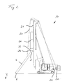
- FIGS. 1 to 3 the course of a method according to the invention is explained, which is carried out on a piling device 10 according to the invention.
- the pile driver 10 has a crawler undercarriage 12 and an upper carriage 14 rotatably mounted thereon.
- a mast 16 with mast head 17 is mounted in a known manner via a Anlenkkinematik 18 with actuating cylinder 19 adjustable. In operating position, the mast 16 is in a vertical orientation, which in Fig. 1 is shown.
- a non-illustrated linear guide is provided, along which a hammer unit 30 is guided and supported vertically displaceable.
- a main winch 20 is arranged in the uppercarriage 14, which is connected to the hammer unit 30 via a main cable 21 guided via the mast head 17.
- the main winch 20 is driven by a hydraulic motor, not shown.
- the hammer unit 30 has, in a known manner, a striker unit, which is driven by a percussion drive, such as a diesel engine or a hydraulic drive, to generate impact pulses.
- a percussion drive such as a diesel engine or a hydraulic drive
- the approximately cylindrical receiving space 34 is open at the bottom.
- the receiving space 34 is designed to receive a head region 5 of a pile element 4 to be engraved in order to transfer the impact pulses generated by the hammer unit 30 to the pile element 4 via the driving cap 32.
- an auxiliary winch 22 with an auxiliary cable 23 is provided on the superstructure 14 in addition to the main winch 20, which is guided via rollers on the mast head 17.
- the free end of the auxiliary cable 23 is fixed in a conventional manner, such as a hook means in an upper region of the pile element 4 at this.
- the hammer unit 30 is moved on the mast 16 in a lower initial position, which approximately in Fig. 1 is shown.
- the auxiliary winch 22 driven by a hydraulic motor by an operator, the head portion 5 of the pile member 4 is raised, while a tip 6 of the pile member 4 is supported on the ground 8.
- the pile element 4 is raised with the auxiliary winch 22 in a single control by an operator until the head portion 5 of the pile element 4 rests against the underside of the Rammhaube 32 with a desired pressure force.
- the pressing force can be predetermined by the operator on the basis of his experience or determined and adjusted by means of a measuring device with a force-measuring sensor on the auxiliary winch 22.
- an automatic control program is activated in the control device of the piling device 10, through which now the main winch 20 and the auxiliary winch 22 are operated defined for erecting the pile element 4.
- the main cable 21 and the auxiliary cable 23 are pulled in synchronized with each other synchronously, so that the hammer unit 30 moves along the mast 16 upwards.
- the pile element 4 is pulled upwards by the auxiliary cable 23, whereby the control takes place in such a way that the head region 5 of the pile element 4 always rests against the driving hood 32 with the desired pressure force. Since the pile element 4 is still supported on the top 6 on the bottom 8, is prevented by this double support of the pile element 4 during the erection that the pile element 4 gets into an undesirable swing.
- the up-pulling of the pile element 4 and the hammer unit 30 takes place until the in Fig. 3 shown operating and piling position is reached.
- the pile element 4 In the ramming position, the pile element 4 is arranged approximately vertically and the head region 5 of the pile element 4 is suitably received in the receiving space 34 of the driving hood 32.
- a guide and retaining claw 36 which is attached to a lower region of the mast 16, be pivoted to the pile element 4 in order to additionally guide this during subsequent ramming.
- the pile member 4 can be driven to a desired depth in the bottom 8.
Landscapes
- Engineering & Computer Science (AREA)
- Mining & Mineral Resources (AREA)
- Life Sciences & Earth Sciences (AREA)
- General Engineering & Computer Science (AREA)
- General Life Sciences & Earth Sciences (AREA)
- Structural Engineering (AREA)
- Civil Engineering (AREA)
- Paleontology (AREA)
- Geology (AREA)
- Mechanical Engineering (AREA)
- Physics & Mathematics (AREA)
- Environmental & Geological Engineering (AREA)
- Fluid Mechanics (AREA)
- Geochemistry & Mineralogy (AREA)
- Placing Or Removing Of Piles Or Sheet Piles, Or Accessories Thereof (AREA)
Abstract
Description
- Die Erfindung betrifft ein Rammgerät zum Einrammen eines Pfahlelementes in den Boden mit einem Mast, einer angetriebenen Hammereinheit, welche entlang des Mastes verfahrbar gelagert ist und in einem unteren Bereich eine Rammhaube aufweist, welche zum Aufnehmen eines Kopfbereiches des einzurammenden Pfahlelementes ausgebildet ist, einer Hauptwinde mit Hauptseil, welches mit der Hammereinheit zum Verfahren der Hammereinheit entlang des Mastes verbunden ist, und einer Hilfswinde mit Hilfsseil, welches über den Mast geführt ist und mit einem einzurammenden Pfahlelement verbindbar ist, wobei mittels der Hilfswinde das einzurammende Pfahlelement von einer liegenden Position in eine etwa vertikale Rammposition aufstellbar ist, bei welcher der Kopfbereich des Pfahlelementes in der Rammhaube der Hammereinheit aufgenommen ist, gemäß dem Oberbegriff des Anspruchs 1.
- Die Erfindung betrifft weiterhin ein Verfahren zum Einrammen eines Pfahlelementes in den Boden, wobei ein Kopfbereich des Pfahlelementes in einer Rammhaube an einer Unterseite einer angetriebenen Hammereinheit angeordnet wird, welche mittels einer Hauptwinde mit einem Hauptseil entlang eines Mastes verfahren wird und das Pfahlelement in einer etwa vertikalen Rammposition in den Boden einrammt, wobei das Pfahlelement mittels einer Hilfswinde mit Hilfsseil von einer liegenden Position in die etwa vertikale Rammposition aufgestellt wird, bei welcher der Kopfbereich des Pfahlelementes in der Rammhaube der Hammereinheit aufgenommen ist, gemäß dem Oberbegriff des Anspruchs 7.
- Derartige Rammgeräte und derartige Verfahren werden bei Gründungsmaßnahmen eingesetzt, bei welchen Pfahlelemente in einen relativ weichen Boden eingetrieben werden. Hierzu weist das Rammgerät eine Hammereinheit auf, welche abhängig von der Antriebsart ein sogenannter Diesel-Hammer oder ein Hydraulik-Hammer sein kann. Die Hammereinheit erzeugt Schlagimpulse, welche auf den Kopfbereich eines Pfahlelementes aufgebracht werden, so dass das Pfahlelement in den Boden eingetrieben wird.
- Für ein derartiges Einrammen ist es erforderlich, das Pfahlelement zunächst in eine etwa vertikale Rammposition zu bringen, bei welcher ein oberer Kopfbereich des Pfahlelementes in einer Rammhaube der Hammereinheit aufgenommen ist. Über die topfartige Rammhaube werden die Schlagimpulse auf das Pfahlelement übertragen.
- Die Pfahlelemente, welche üblicherweise aus Stahl oder Beton gebildet sind, müssen dabei zunächst aus einer typischerweise liegenden Transort- oder Lagerposition in die vertikale Betriebs- oder Rammposition aufgestellt werden. Hierzu befindet sich am Mast des Rammgerätes eine Hilfswinde mit einem Hilfsseil, dessen freies Ende in einem oberen Bereich des Pfahlelementes befestigt wird, so dass das Pfahlelement aus der liegenden Position mit der Hilfswinde in die vertikale Rammposition aufgestellt werden kann.
- Dieses Aufstellen des Pfahlelementes und auch das notwendige Einfädeln des Kopfes des Pfahlelementes in die Rammhaube erfordert von einem Bediener große Erfahrung und Geschicklichkeit. Neben einer Steuerung der Hilfswinde ist es teilweise erforderlich, das Pfahlelement von Hand in die genaue Position unterhalb der Hammereinheit zu bringen. Zudem muss für ein Einfädeln in die Rammhaube neben der Hilfswinde auch die Position der Hammereinheit am Mast über eine Hauptwinde koordiniert verstellt werden.
- Diese Einfädelarbeiten sind zeit- und personalaufwändig, wobei zudem Justierarbeiten des Pfahlelementes von Hand im unmittelbaren Arbeitsbereich des Rammgerätes aus Gründen der Betriebssicherheit möglichst zu vermeiden sind.
- Zudem besteht bei einem Aufstellen des Pfahlelementes in die Rammposition mittels der Hilfswinde die Gefahr, dass das bis zu 10 m und mehr lange Pfahlelement an dem Hilfsseil in ein Schwingen oder Pendeln gerät. Ein pendelndes Pfahlelement kann das Rammgerät beschädigen oder die Verbindung zum Hilfsseil kann sich lösen, was ebenso zu Sach- oder gar Personenschäden führen kann.
- Der Erfindung liegt die Aufgabe zugrunde, ein Rammgerät und ein Verfahren zum Einrammen eines Pfahlelementes anzugeben, mit welchen ein effizienter und besonders sicherer Betrieb möglich ist.
- Die Aufgabe wird zum einen durch ein Rammgerät mit den Merkmalen des Anspruchs 1 und zum anderen mit einem Verfahren mit den Merkmalen des Anspruchs 7 gelöst. Bevorzugte Ausführungen der Erfindung sind in den jeweils abhängigen Ansprüchen angegeben.
- Das erfindungsgemäße Rammgerät ist dadurch gekennzeichnet, dass eine Steuereinrichtung zum gleichzeitigen automatischen Steuern der Hauptwinde und der Hilfswinde vorgesehen ist und dass beim Aufstellen des einzurammenden Pfahlelementes die Hauptwinde und die Hilfswinde durch die Steuereinrichtung gesteuert sind, so dass die Hammereinheit von einer unteren Anfangsposition am Mast durch die Hauptwinde verfahrbar ist und der Kopfbereich des Pfahlelementes während des Aufstellens mittels der Hilfswinde an der Rammhaube mit einer vorgebbaren Andruckkraft anliegt.
- Ein erster Aspekt der Erfindung besteht darin, dass beim Aufstellen des Pfahlelementes aus einer liegenden Position in die Rammposition ein Kopfbereich des Pfahlelementes an der Rammhaube der Hammereinheit definiert anliegt. Damit befindet sich das Pfahlelement während des Aufstellens stets in Kontakt einerseits mit dem Boden und andererseits mit der Rammhaube. Durch diese mehrfache Kontaktierung wird der Gefahr eines Schwingens des Pfahlelementes beim Aufstellen wirksam vorgebeugt.
- Ein weiterer Aspekt der Erfindung liegt darin, dass das Anliegen des Pfahlelementes an der Rammhaube mit einer definierten Andruckkraft während des Aufstellens durch ein gleichzeitiges automatisches Steuern der Hauptwinde zum Verstellen der Hammereinheit und der Hilfswinde zum Verstellen des Pfahlelementes durch eine Steuereinrichtung gesteuert wird. Dies gewährleistet einen effizienten, zuverlässigen und damit sicheren Betrieb beim Aufstellen des Pfahlelementes. Im Sinne der Erfindung ist die vorgebbare Andruckkraft kein einzelner Kraftwert, sondern vorzugsweise ein Kraftwertbereich, welcher durch einen unteren Minimalwert und einen oberen Maximalwert vorgegeben wird. Der Minimalwert muss dabei so groß sein, dass das Pfahlelement während des Aufstellens sicher an der Rammhaube verbleibt, während der Maximalwert so gewählt ist, dass durch die Andruckkraft die Rammhaube nicht beschädigt wird.
- Eine bevorzugte Ausführungsform der Erfindung besteht darin, dass die Steuereinrichtung eine Eingabeeinrichtung zum Einstellen der Andruckkraft aufweist. Die Eingabeeinrichtung kann dabei zweckmäßigerweise ein einfacher Regler oder ein Potentiometer sein, mit welchem ein Bediener die Hilfswinde und/oder die Hauptwinde so steuert, dass eine gewünschte Andruckkraft des Pfahlelementes an der Rammhaube bewirkt wird. Neben einer derartigen stufenlos einstellbaren Eingabeeinrichtung können auch Vorgabetasten mit Standardandruckkraftwerten vorgegeben sein. Grundsätzlich ist es auch möglich, eine Tastatur vorzusehen, so dass die Andruckkraft numerisch vorgebbar ist.
- Grundsätzlich können die Winden beliebig angetrieben sein. Eine besonders zweckmäßige Ausführungsform der Erfindung ergibt sich dadurch, dass die Hauptwinde und die Hilfswinde jeweils einen Hydraulikmotor aufweisen und dass durch die Steuereinrichtung die Zuführung von Hydraulikfluid in einen der Hydraulikmotoren oder in beiden Hydraulikmotoren zum Einstellen der Andruckkraft gesteuert ist. Zum einen sind Hydraulikmotoren besonders kompakt und ermöglichen eine effiziente Kraftaufbringung. Die Steuerung durch Veränderung der Zuführung von Hydraulikfluid zu einem Hydraulikmotor, etwa durch Änderung des Volumenstromes oder des Hydraulikdruckes, ermöglichen zum anderen eine schnelle und genaue Steuerung der Windenantriebe.
- Eine vorteilhafte Weiterbildung der Erfindung ergibt sich dadurch, dass zur Steuerung des mindestens einen Hydraulikmotors in einer Zuführleitung ein hydraulisches Druckregelventil angeordnet ist, welches über die Steuereinrichtung betätigbar ist. Vorzugsweise befindet sich das hydraulische Druckregelventil lediglich in der Zuführung zu einem Hydraulikmotor, insbesondere zu dem Hydraulikmotor der Hauptwinde. Hierdurch lässt sich die Drehgeschwindigkeit und/oder die Zugkraft der Winde sehr genau einstellen.
- Gemäß einer weiteren Ausführungsform der Erfindung ist es vorteilhaft, dass beim Aufstellen des Pfahlelementes die Hilfswinde mit einer größeren Drehgeschwindigkeit und/oder Zugkraft als die Drehgeschwindigkeit beziehungsweise Zugkraft der Hauptwinde betrieben ist. Hierdurch wird erreicht, dass das Pfahlelement stets mit der gewünschten Andruckkraft zuverlässig an der Rammhaube der Hammereinheit anliegt. Insbesondere wird so vermieden, dass die Hammereinheit durch die Hauptwinde zu schnell nach oben verfahren wird und der Kopfbereich des Pfahlelementes den Kontakt mit der Rammhaube verliert. Zudem ist die Hilfswinde so zu steuern oder einzustellen, dass eine Spitze des Pfahlelementes sich am Boden abstützt.
- Eine weitere Verbesserung der Bedienbarkeit wird nach einer Ausführungsform der Erfindung dadurch erreicht, dass die Steuereinrichtung einen Schalter aufweist, mit welchem zwischen einer Einzelsteuerung von Hauptwinde und Hilfswinde und einer gemeinsamen automatischen Steuerung umgeschaltet werden kann. Die Steuereinrichtung kann dabei eine tragbare manuelle Einheit aufweisen, an welcher die Eingabeeinrichtung und der Schalter angeordnet sind. Es besteht so für einen Bediener weiter die Möglichkeit, die Hauptwinde und damit die Hammereinheit und die Hilfswinde und damit das Pfahlelement weiterhin unabhängig voneinander zu bedienen und zu verstellen. Für ein sicheres und zuverlässiges Aufstellen kann der Bediener jedoch auf die automatische Steuerung umschalten, so dass nach einem anfänglichen Justieren und Anlegen des Kopfbereiches des Pfahlelementes an der Rammhaube ein automatisches Aufstellen und Einfädeln des Pfahlelementes an der Hammereinheit durchgeführt wird.
- Das erfindungsgemäße Verfahren zum Einrammen eines Pfahlelementes in den Boden ist dadurch gekennzeichnet, dass beim Aufstellen des einzurammenden Pfahlelementes die Hauptwinde und die Hilfswinde gleichzeitig durch eine Steuereinrichtung automatisch gesteuert werden, so dass der Kopfbereich des Pfahlelementes während des Aufstellens an den Rammhaube mit einer vorgebbaren Andruckkraft anliegt.
- Das Verfahren kann insbesondere durch das vorausgehend beschriebene Rammgerät durchgeführt werden. Es können mit dem erfindungsgemäßen Verfahren die vorausgehend beschriebenen Vorteile erzielt werden.
- Grundsätzlich kann eine fest vorgegebene Andruckkraft in der Steuereinrichtung hinterlegt sein. Bevorzugt ist es nach einer Variante der Erfindung, dass die Andruckkraft mittels der Steuereinrichtung eingestellt wird. Dies kann über einen Regler, insbesondere ein Potentiometer, oder über ein numerisches Eingabefeld erfolgen. Die Andruckkraft kann so an unterschiedliche Größen und Gewichte des Pfahlelementes angepasst werden.
- Zur Druckeinstellung besteht eine vorteilhafte Ausführungsvariante der Erfindung darin, dass zum Einstellen der Andruckkraft die Hilfswinde betätigt und das Pfahlelement an die Rammhaube angedrückt wird, während die Hauptwinde stillsteht und die Hammereinheit sich in einer unteren Anfangsposition an dem Mast befindet und dass anschließend durch die Steuereinrichtung die Hauptwinde und die Hilfswinde betätigt werden, wobei die Hammereinheit von der unteren Anfangsposition entlang des Mastes in eine obere Rammposition verfahren wird, während das Pfahlelement kontinuierlich an die Rammhaube angedrückt wird. Das Einstellen der Andruckkraft kann also in der Praxis durch den Bediener durch ein einfaches Justieren und Andrücken des Pfahlelementes an die Rammhaube erfolgen, während sich die Hammereinheit in einer unteren Anfangsposition an dem Mast befindet.
- Grundsätzlich kann an der Winde oder der Rammhaube auch eine Messeinrichtung, insbesondere eine Sensoreinrichtung, vorgesehen sein, mit welcher die momentane Andruckkraft angezeigt wird. Eine derartige Messeinrichtung ist jedoch nicht zwingend notwendig.
- Nach diesem Vorjustieren des Pfahlelementes mit Andrücken an die Rammhaube kann der Aufstellvorgang beginnen, wobei die Hammereinheit gesteuert durch die Hauptwinde nach oben verfahren wird, während das Pfahlelement durch die synchron gesteuerte Hilfswinde das Pfahlelement weiter gegen die nach oben fahrende Hammereinheit andrückt, bis das Pfahlelement die vertikale Endposition erreicht und in den zylindrischen Aufnahmeraum der topfförmigen Rammhaube einfädelt. Der Antrieb der beiden Winden wird sodann gestoppt. Gegebenenfalls wird die Hammereinheit gegenüber dem Rammelement abgesenkt, bis eine ausreichende Schlagkontaktfläche zwischen der Rammhaube und dem oberen Kopfbereich des Pfahlelementes erreicht ist. In der Rammposition kann dann die Hammereinheit in Betrieb gesetzt werden und das Pfahlelement unter einem nach unten Bewegen der Hammereinheit in den Boden eingerammt werden.
- Eine weitere bevorzugte Verfahrensvariante der Erfindung besteht darin, dass während des Aufstellens eine Zuführung von Hydraulikfluid zu einem Hydraulikmotor der Hauptwinde und/oder der Hilfswinde gesteuert wird. Dies ermöglicht eine besonders genaue und schnelle Steuerung des Windenbetriebes.
- Nach einer weiteren Ausführungsform der Erfindung ist es vorteilhaft, dass die Hilfswinde mit einer vorgegebenen Geschwindigkeit und/oder Zugkraft betrieben wird und dass zum Erzeugen der Andruckkraft die Hauptwinde mit einer durch die Steuereinrichtung einstellbaren Geschwindigkeit und/oder Zugkraft betrieben wird. Die Hilfswinde weist somit eine vorgegebene feste Einstellung auf. Damit wird die Andruckkraft durch eine entsprechende Einstellung der Geschwindigkeit und/oder der Zugkraft der Hauptwinde mit dem Hauptseil über die Steuerung eingestellt.
- Grundsätzlich ist aber auch eine feste Einstellung der Hauptwinde möglich, während die Einstellung über eine entsprechende Veränderung des Hilfswindenantriebes erfolgt.
- Nachfolgend wird die Erfindung anhand eines bevorzugten Ausführungsbeispieles erläutert, welches schematisch in den Zeichnungen dargestellt ist. In den Zeichnungen zeigen:
- Fig. 1:
- eine Seitenansicht eines erfindungsgemäßen Rammgerätes beim Aufstellen eines Pfahlelementes in einer Anfangsposition;
- Fig. 2:
- eine Seitenansicht des Rammgerätes von
Fig. 1 während des Aufstellens des Pfahlelementes; und - Fig. 3:
- eine Seitenansicht des Rammgerätes von
Figuren 1 und2 mit aufgestelltem Pfahlelement in einer Rammposition. - In den
Figuren 1 bis 3 ist der Verlauf eines erfindungsgemäßen Verfahrens erläutert, welches auf einem erfindungsgemäßen Rammgerät 10 durchgeführt wird. Das Rammgerät 10 weist einen als Raupenfahrwerk ausgebildeten Unterwagen 12 und einen darauf drehbar gelagerten Oberwagen 14 auf. An dem Oberwagen 14 ist in bekannter Weise über eine Anlenkkinematik 18 mit Stellzylinder 19 ein Mast 16 mit Mastkopf 17 verstellbar angebracht. In Betriebsposition befindet sich der Mast 16 in einer vertikalen Ausrichtung, welche inFig. 1 dargestellt ist. - An einer Vorderseite des Mastes 16 ist eine nicht-dargestellte Linearführung vorgesehen, entlang welcher eine Hammereinheit 30 vertikal verschiebbar geführt und gelagert ist. Zum Verfahren der Hammereinheit 30 ist im Oberwagen 14 eine Hauptwinde 20 angeordnet, welche über ein über den Mastkopf 17 geführtes Hauptseil 21 mit der Hammereinheit 30 in Verbindung steht. Die Hauptwinde 20 wird über einen nicht-dargestellten Hydraulikmotor angetrieben.
- Die Hammereinheit 30 weist in bekannter Weise eine Schlageinheit auf, welche durch einen Schlagantrieb, etwa einen Dieselmotor oder einen Hydraulikantrieb, zur Erzeugung von Schlagimpulsen angetrieben ist. An einer Unterseite der Hammereinheit 30 ist eine topfförmige Rammhaube 32 angeordnet, deren etwa zylindrischer Aufnahmeraum 34 nach unten offen ist. Der Aufnahmeraum 34 ist zum Aufnehmen eines Kopfbereiches 5 eines einzurammenden Pfahlelementes 4 ausgebildet, um die von der Hammereinheit 30 erzeugten Schlagimpulse über die Rammhaube 32 auf das Pfahlelement 4 zu übertragen.
- Zur Durchführung des Rammverfahrens ist es zunächst erforderlich, das Pfahlelement 4 von einer liegenden Lager- oder Transortposition, in welcher das Pfahlelement 4 üblicherweise horizontal gerichtet ist, in eine etwa vertikal gerichtete Betriebsoder Rammposition zu bringen, bei welcher der Kopfbereich 5 des Pfahlelementes 4 in den Aufnahmeraum 34 der Rammhaube 32 eingefädelt ist, wie in
Fig. 3 dargestellt. - Für dieses notwendige Aufstellen des Pfahlelementes 4 ist am Oberwagen 14 zusätzlich zur Hauptwinde 20 eine Hilfswinde 22 mit einem Hilfsseil 23 vorgesehen, welches über Rollen am Mastkopf 17 geführt ist. Das freie Ende des Hilfsseiles 23 wird in an sich bekannter Weise, etwa über eine Hakeneinrichtung, in einem oberen Bereich des Pfahlelementes 4 an diesem befestigt. Zum Aufstellen wird zunächst die Hammereinheit 30 am Mast 16 in eine untere Anfangsposition verfahren, welche näherungsweise in
Fig. 1 dargestellt ist. Durch Betätigen der über einen Hydraulikmotor angetriebenen Hilfswinde 22 durch einen Bediener wird der Kopfbereich 5 des Pfahlelementes 4 angehoben, während sich eine Spitze 6 des Pfahlelementes 4 am Boden 8 abstützt. - Dabei wird das Pfahlelement 4 mit der Hilfswinde 22 in einer Einzelansteuerung durch einen Bediener soweit angehoben, bis der Kopfbereich 5 des Pfahlelementes 4 an der Unterseite der Rammhaube 32 mit einer gewünschten Andruckkraft anliegt. Die Andruckkraft kann durch den Bediener aufgrund seiner Erfahrung vorgegeben oder mittels einer Messeinrichtung mit einem Kraftmess-Sensor an der Hilfswinde 22 bestimmt und eingestellt werden.
- Nachdem der Anfangszustand gemäß
Fig. 1 erreicht ist, wird gemäß der Erfindung ein automatisches Steuerprogramm in der Steuereinrichtung des Rammgerätes 10 aktiviert, durch welches nunmehr die Hauptwinde 20 und die Hilfswinde 22 zum Aufrichten des Pfahlelementes 4 definiert betätigt werden. Dabei werden das Hauptseil 21 und das Hilfsseil 23 abgestimmt aufeinander synchron eingezogen, so dass die Hammereinheit 30 entlang des Mastes 16 nach oben fährt. Gleichzeitig wird durch das Hilfsseil 23 das Pfahlelement 4 nach oben gezogen, wobei die Steuerung derart erfolgt, dass der Kopfbereich 5 des Pfahlelementes 4 stets mit der gewünschten Andruckkraft an der Rammhaube 32 anliegt. Da das Pfahlelement 4 sich weiterhin über die Spitze 6 am Boden 8 abstützt, wird so durch diese zweifache Abstützung des Pfahlelementes 4 während der Aufstellbewegung verhindert, dass das Pfahlelement 4 in ein unerwünschtes Schwingen gerät. - Wie aus der Darstellung gemäß
Fig. 2 hervorgeht, wird bei diesem gesteuerten nach-oben-Ziehen von Pfahlelement 4 und Hammereinheit 30 der Kopfbereich 5 des Pfahlelementes 4 allmählich in den Aufnahmeraum 34 der Rammhaube 32 eingefädelt. Hierbei kann die Rammhaube 32 in den zylindrischen Wandbereich, welcher den Aufnahmeraum 34 umgibt, eine nicht-dargestellte, zum Aufnahmeraum 34 gerichtete Einlaufschräge aufweisen, durch welche das schräge Einführen des Kopfbereiches 5 in den Aufnahmeraum 34 unterstützt wird. - Das nach-oben-Ziehen des Pfahlelementes 4 und der Hammereinheit 30 erfolgt solange, bis die in
Fig. 3 dargestellte Betriebs- und Rammposition erreicht ist. In der Rammposition ist das Pfahlelement 4 etwa vertikal angeordnet und der Kopfbereich 5 des Pfahlelementes 4 ist passend in dem Aufnahmeraum 34 der Rammhaube 32 aufgenommen. Zur zusätzlichen Führung des Pfahlelementes 4 kann eine Führungsund Halteklaue 36, welche an einem unteren Bereich des Mastes 16 angebracht ist, an das Pfahlelement 4 angeschwenkt werden, um dieses beim nachfolgenden Einrammen zusätzlich zu führen. - Sodann kann das Pfahlelement 4 bis zu einer gewünschten Tiefe in den Boden 8 eingetrieben werden.
Claims (11)
- Rammgerät zum Einrammen eines Pfahlelementes (4) in den Boden (8) mit- einem Mast (16),- einer angetriebenen Hammereinheit (30), welche entlang des Mastes (16) verfahrbar gelagert ist und in einem unteren Bereich eine Rammhaube (32) aufweist, welche zum Aufnehmen eines Kopfbereiches (5) des einzurammenden Pfahlelementes (4) ausgebildet ist,- einer Hauptwinde (20) mit Hauptseil (21), welches mit der Hammereinheit (30) zum Verfahren der Hammereinheit (30) entlang des Mastes (16) verbunden ist, und- einer Hilfswinde (22) mit Hilfsseil (23), welches über den Mast (16) geführt ist und mit einem einzurammenden Pfahlelement (4) verbindbar ist, wobei mittels der Hilfswinde (22) das einzurammende Pfahlelement (4) von einer liegenden Position in eine etwa vertikale Rammposition aufstellbar ist, bei welcher der Kopfbereich (5) des Pfahlelementes (4) in der Rammhaube (32) der Hammereinheit (30) aufgenommen ist,
dadurch gekennzeichnet,- dass eine Steuereinrichtung zum gleichzeitigen automatischen Steuern der Hauptwinde (20) und der Hilfswinde (22) vorgesehen ist und- dass beim Aufstellen des einzurammenden Pfahlelementes (4) die Hauptwinde (20) und die Hilfswinde (22) durch die Steuereinrichtung gesteuert sind, so dass die Hammereinheit (30) von einer unteren Anfangsposition am Mast (16) durch die Hauptwinde (20) verfahrbar ist und der Kopfbereich (5) des Pfahlelementes (4) während des Aufstellens mittels der Hilfswinde (22) an der Rammhaube (32) mit einer vorgebbaren Andruckkraft anliegt. - Rammgerät nach Anspruch 1,
dadurch gekennzeichnet,
dass die Steuereinrichtung eine Eingabeeinrichtung zum Einstellen der Andruckkraft aufweist. - Rammgerät nach Anspruch 1 oder 2,
dadurch gekennzeichnet,
dass die Hauptwinde (20) und die Hilfswinde (22) jeweils einen Hydraulikmotor aufweisen und
dass durch die Steuereinrichtung die Zuführung von Hydraulikfluid in einen der Hydraulikmotoren oder in beiden Hydraulikmotoren zum Einstellen der Andruckkraft gesteuert ist. - Rammgerät nach Anspruch 3,
dadurch gekennzeichnet,
dass zur Steuerung des mindestens einen Hydraulikmotors in einer Zuführleitung ein hydraulisches Druckregelventil angeordnet ist, welches über die Steuereinrichtung betätigbar ist. - Rammgerät nach einem der Ansprüche 1 bis 4,
dadurch gekennzeichnet,
dass beim Aufstellen des Pfahlelementes (4) die Hilfswinde (22) mit einer größeren Drehgeschwindigkeit und/oder Zugkraft als die Drehgeschwindigkeit beziehungsweise Zugkraft der Hauptwinde (20) betrieben ist. - Rammgerät nach einem der Ansprüche 1 bis 5,
dadurch gekennzeichnet,
dass die Steuereinrichtung einen Schalter aufweist, mit welchem zwischen einer Einzelsteuerung von Hauptwinde (20) und Hilfswinde (22) und einer gemeinsamen automatischen Steuerung umschaltbar ist. - Verfahren zum Einrammen eines Pfahlelementes (4) in den Boden (8), insbesondere mit einem Rammgerät (10) nach einem der Ansprüche 1 bis 6,
wobei ein Kopfbereich (5) des Pfahlelementes (4) in einer Rammhaube (32) an einer Unterseite einer angetriebenen Hammereinheit (30) angeordnet wird, welche mittels einer Hauptwinde (20) mit einem Hauptseil (21) entlang eines Mastes (16) verfahren wird und das Pfahlelement (4) in einer etwa vertikalen Rammposition in den Boden (8) einrammt, wobei das Pfahlelement (4) mittels einer Hilfswinde (22) mit Hilfsseil (23) von einer liegenden Position in die etwa vertikale Rammposition aufgestellt wird, bei welcher der Kopfbereich (5) des Pfahlelementes (4) in der Rammhaube (32) der Hammereinheit (30) aufgenommen ist,
dadurch gekennzeichnet,
dass beim Aufstellen des einzurammenden Pfahlelementes (4) die Hauptwinde (20) und die Hilfswinde (22) gleichzeitig durch eine Steuereinrichtung automatisch gesteuert werden, so dass der Kopfbereich (5) des Pfahlelementes (4) während des Aufstellens an der Rammhaube (32) mit einer vorgebbaren Andruckkraft anliegt. - Verfahren nach Anspruch 7,
dadurch gekennzeichnet,
dass die Andruckkraft mittels der Steuereinrichtung eingestellt wird. - Verfahren nach Anspruch 8,
dadurch gekennzeichnet,
dass zum Einstellen der Andruckkraft die Hilfswinde (22) betätigt und das Pfahlelement (4) an die Rammhaube (32) angedrückt wird, während die Hauptwinde (20) still steht und die Hammereinheit (30) sich in einer unteren Anfangsposition an dem Mast (16) befindet, und
dass anschließend durch die Steuereinrichtung die Hauptwinde (20) und die Hilfswinde (22) betätigt werden, wobei die Hammereinheit (30) von der unteren Anfangsposition entlang des Mastes (16) in eine obere Rammposition verfahren wird, während das Pfahlelement (4) kontinuierlich an die Rammhaube (32) angedrückt wird. - Verfahren nach einem der Ansprüche 7 bis 9,
dadurch gekennzeichnet,
dass während des Aufstellens eine Zuführung von Hydraulikfluid zu einem Hydraulikmotor der Hauptwinde (20) und/oder der Hilfswinde (22) gesteuert wird. - Verfahren nach einem der Anspruch 1 bis 10,
dadurch gekennzeichnet,
dass die Hilfswinde (22) mit einer vorgegebenen Geschwindigkeit und/oder Zugkraft betrieben wird und
dass zum Erzeugen der Andruckkraft die Hauptwinde (20) mit einer durch die Steuereinrichtung einstellbaren Geschwindigkeit und/oder Zugkraft betrieben wird.
Priority Applications (5)
| Application Number | Priority Date | Filing Date | Title |
|---|---|---|---|
| EP14186393.6A EP3000942B1 (de) | 2014-09-25 | 2014-09-25 | Rammgerät und Verfahren zum Einrammen eines Pfahlelementes in den Boden |
| DK14186393.6T DK3000942T3 (en) | 2014-09-25 | 2014-09-25 | Dispensing device and method for impounding a pile element in the ground |
| ES14186393.6T ES2626780T3 (es) | 2014-09-25 | 2014-09-25 | Aparato de hincado y procedimiento para hincar un elemento de pilote en el suelo |
| RU2015137964A RU2633454C2 (ru) | 2014-09-25 | 2015-09-07 | Сваебойная машина и способ забивки свайных элементов в грунт |
| US14/864,599 US9464398B2 (en) | 2014-09-25 | 2015-09-24 | Pile-driving apparatus and method for driving a pile element into the ground |
Applications Claiming Priority (1)
| Application Number | Priority Date | Filing Date | Title |
|---|---|---|---|
| EP14186393.6A EP3000942B1 (de) | 2014-09-25 | 2014-09-25 | Rammgerät und Verfahren zum Einrammen eines Pfahlelementes in den Boden |
Publications (2)
| Publication Number | Publication Date |
|---|---|
| EP3000942A1 true EP3000942A1 (de) | 2016-03-30 |
| EP3000942B1 EP3000942B1 (de) | 2017-03-15 |
Family
ID=51589213
Family Applications (1)
| Application Number | Title | Priority Date | Filing Date |
|---|---|---|---|
| EP14186393.6A Active EP3000942B1 (de) | 2014-09-25 | 2014-09-25 | Rammgerät und Verfahren zum Einrammen eines Pfahlelementes in den Boden |
Country Status (5)
| Country | Link |
|---|---|
| US (1) | US9464398B2 (de) |
| EP (1) | EP3000942B1 (de) |
| DK (1) | DK3000942T3 (de) |
| ES (1) | ES2626780T3 (de) |
| RU (1) | RU2633454C2 (de) |
Cited By (3)
| Publication number | Priority date | Publication date | Assignee | Title |
|---|---|---|---|---|
| EP3708714A1 (de) * | 2019-03-13 | 2020-09-16 | BAUER Maschinen GmbH | Sicherungsvorrichtung zum sichern eines tiefbauelementes und tiefbauverfahren |
| IT202000030965A1 (it) * | 2020-12-16 | 2022-06-16 | Orteco S R L | Macchina per l’infissione di pali nel terreno |
| EP4671449A1 (de) * | 2024-06-26 | 2025-12-31 | ABI Anlagentechnik-Baumaschinen-Industriebedarf Maschinenfabrik und Vertriebsgesellschaft mbH | Vorrichtung und verfahren zum sichern eines tiefbauelementes an einer tiefbaumaschine |
Families Citing this family (14)
| Publication number | Priority date | Publication date | Assignee | Title |
|---|---|---|---|---|
| SG11201908187QA (en) * | 2017-03-13 | 2019-10-30 | Giken Ltd | Pile press-in machine and pile press-in method |
| JP6562364B2 (ja) * | 2017-11-10 | 2019-08-21 | 五洋建設株式会社 | 管杭の吊り起こし装置及び管杭の吊り起こし方法 |
| US20190264411A1 (en) * | 2018-02-23 | 2019-08-29 | Clark Equipment Company | Post driving implement |
| IT201900013833A1 (it) * | 2019-08-02 | 2021-02-02 | Orteco S R L | Apparecchiatura per l’infissione di pali nel terreno |
| US10954645B2 (en) * | 2019-08-23 | 2021-03-23 | Christopher DeBlauw | System and apparatus for driving piles |
| CN111622220B (zh) * | 2020-06-05 | 2021-06-29 | 浙江广厦建设职业技术学院 | 一种土木施工用打桩装置 |
| RU201332U1 (ru) * | 2020-07-23 | 2020-12-09 | Андрей Александрович Щербина | Сваебойка |
| IT202000025255A1 (it) * | 2020-10-26 | 2022-04-26 | Soilmec Spa | Macchina da fondazioni e metodo per il controllo di tale macchina |
| CA3109696A1 (en) * | 2021-02-19 | 2022-08-19 | Jason Linley | A mast and grapple combination |
| JP7661120B2 (ja) | 2021-05-13 | 2025-04-14 | 株式会社技研製作所 | 杭吊上補助具 |
| RU210391U1 (ru) * | 2021-10-15 | 2022-04-14 | Общество с ограниченной ответственностью «Техноперспектива» | Сваебойная машина |
| CN114592517B (zh) * | 2022-03-21 | 2023-03-21 | 浙江大学 | 带扩大桩靴桩身自重锤击施工工艺 |
| CN115467330B (zh) * | 2022-07-29 | 2024-11-01 | 武汉理工大学 | 一种沉桩消声装置及安装方法 |
| CN116024972A (zh) * | 2023-01-06 | 2023-04-28 | 华电重工股份有限公司 | 一种打桩设备和打桩系统 |
Citations (2)
| Publication number | Priority date | Publication date | Assignee | Title |
|---|---|---|---|---|
| US2134989A (en) * | 1936-05-11 | 1938-11-01 | John B Templeton | Pile-driving attachment for booms |
| GB771037A (en) * | 1954-06-30 | 1957-03-27 | Landsverk Ab | A method and a device for pile driving by means of a self-propelled pile driver |
Family Cites Families (15)
| Publication number | Priority date | Publication date | Assignee | Title |
|---|---|---|---|---|
| GB938592A (en) * | 1960-08-24 | 1963-10-02 | Lehane Mackenzie & Shand Ltd | Improvements relating to piling frames |
| SE305629B (de) * | 1965-04-26 | 1968-10-28 | J Johansson | |
| SU372321A1 (ru) * | 1970-09-28 | 1973-03-01 | Авторы изобретени витель | УСТРОЙСТВО дл БУРЕНИЯ СКВАЖИН |
| US3827508A (en) * | 1973-01-05 | 1974-08-06 | Foundation Equipment Corp | Mechanical safety pile monkey |
| JPS5431605B2 (de) * | 1974-09-24 | 1979-10-08 | ||
| SU909013A1 (ru) * | 1979-12-20 | 1982-02-28 | Всесоюзный конструкторско-технологический институт по механизации монтажных и специальных строительных работ | Свайный копер |
| SU1188245A1 (ru) * | 1983-07-01 | 1985-10-30 | Сыктывкарское Проектно-Конструкторское Технологическое Бюро Минлеспрома Ссср | Свайный копер |
| DE3328159A1 (de) * | 1983-08-04 | 1985-02-14 | Martin Oetken GmbH & Co KG, 2900 Oldenburg | Rammgeraet mit von einem baggerausleger gehaltenen haenge-senk-maekler |
| SU1357500A1 (ru) * | 1985-11-26 | 1987-12-07 | Tsytlenok Aleksandr L | Устройство дл погружени свай |
| SU1628606A1 (ru) * | 1989-07-28 | 1996-10-10 | Дальневосточный научно-исследовательский, проектно-конструкторский и технологический институт по строительству | Копровая установка |
| SU1760015A1 (ru) * | 1990-11-16 | 1992-09-07 | Всесоюзное проектно-изыскательское и научно-исследовательское объединение "Гидропроект" им.С.Я.Жука | Копрова установка |
| US5375664A (en) * | 1993-06-15 | 1994-12-27 | Mcdowell; Michael M. | Pile driver |
| US7198115B2 (en) * | 2004-05-06 | 2007-04-03 | Cruz Construction Corp. | Lead alignment attachment |
| CA2468358C (en) * | 2004-06-18 | 2005-05-03 | Subterranean Ltd. | Pile installation method with downhole hammer |
| US7575398B2 (en) * | 2006-08-17 | 2009-08-18 | Deep Foundations Contractors, Inc | Automatic spotter with electronic control system for pile driving and continuous flight auger drilling leads |
-
2014
- 2014-09-25 ES ES14186393.6T patent/ES2626780T3/es active Active
- 2014-09-25 DK DK14186393.6T patent/DK3000942T3/en active
- 2014-09-25 EP EP14186393.6A patent/EP3000942B1/de active Active
-
2015
- 2015-09-07 RU RU2015137964A patent/RU2633454C2/ru active
- 2015-09-24 US US14/864,599 patent/US9464398B2/en not_active Expired - Fee Related
Patent Citations (2)
| Publication number | Priority date | Publication date | Assignee | Title |
|---|---|---|---|---|
| US2134989A (en) * | 1936-05-11 | 1938-11-01 | John B Templeton | Pile-driving attachment for booms |
| GB771037A (en) * | 1954-06-30 | 1957-03-27 | Landsverk Ab | A method and a device for pile driving by means of a self-propelled pile driver |
Cited By (5)
| Publication number | Priority date | Publication date | Assignee | Title |
|---|---|---|---|---|
| EP3708714A1 (de) * | 2019-03-13 | 2020-09-16 | BAUER Maschinen GmbH | Sicherungsvorrichtung zum sichern eines tiefbauelementes und tiefbauverfahren |
| US11174613B2 (en) | 2019-03-13 | 2021-11-16 | Bauer Maschinen Gmbh | Securing means for securing a civil engineering element, and civil engineering method |
| IT202000030965A1 (it) * | 2020-12-16 | 2022-06-16 | Orteco S R L | Macchina per l’infissione di pali nel terreno |
| WO2022130170A1 (en) * | 2020-12-16 | 2022-06-23 | Orteco - S.R.L. | Machine for the introduction of poles into the ground |
| EP4671449A1 (de) * | 2024-06-26 | 2025-12-31 | ABI Anlagentechnik-Baumaschinen-Industriebedarf Maschinenfabrik und Vertriebsgesellschaft mbH | Vorrichtung und verfahren zum sichern eines tiefbauelementes an einer tiefbaumaschine |
Also Published As
| Publication number | Publication date |
|---|---|
| ES2626780T3 (es) | 2017-07-26 |
| US9464398B2 (en) | 2016-10-11 |
| US20160090707A1 (en) | 2016-03-31 |
| EP3000942B1 (de) | 2017-03-15 |
| RU2015137964A (ru) | 2017-03-13 |
| RU2633454C2 (ru) | 2017-10-12 |
| DK3000942T3 (en) | 2017-06-12 |
Similar Documents
| Publication | Publication Date | Title |
|---|---|---|
| EP3000942B1 (de) | Rammgerät und Verfahren zum Einrammen eines Pfahlelementes in den Boden | |
| EP3705629B1 (de) | Rammvorrichtung und verfahren zum einrammen in einen boden | |
| AT513118B1 (de) | Seilsäge | |
| EP2975208A2 (de) | Baumaschine und verfahren zum steuern einer baumaschine | |
| EP1068402A1 (de) | Gerät zum Einbringen eines Fremdstoffes in Böden und/oder zur Verdichtung des Bodens und Verfahren zur Herstellung einer Materialsäule im Boden | |
| EP3670753B1 (de) | Rammvorrichtung und verfahren zum einrammen von rammgut | |
| DE2542012C3 (de) | Vorrichtung zum Eintreiben eines Rammpfahles | |
| DE69000667T2 (de) | Vorrichtung zum herstellen von pfaehlen im boden mit einem kontinuierlichen hohlen bohrer. | |
| EP3084537B1 (de) | Verfahren zur steuerung eines gerätesystems mit einem werkzeuggerät und einer motorischen vorschubeinrichtung | |
| DE2535865C3 (de) | Vorrichtung zum Eintreiben von Spundbohlen | |
| EP3269882B1 (de) | Rammvorrichtung | |
| EP3091173B1 (de) | Bohranlage zum erzeugen oder aufweiten einer erdbohrung im erdreich und verfahren zur steuerung eines vorschubantriebs einer solchen bohranlage | |
| EP4215717B1 (de) | Baumaschine und verfahren zum betreiben einer baumaschine | |
| EP0263967A1 (de) | Tauchfähige Rammvorrichtung | |
| DE2065907C3 (de) | Vorrichtung zur selbsttätigen Erzielung einer vorwählbaren, während der gesamten Rammung konstanten Fallhöhe eines Rammhammers | |
| EP3415708B1 (de) | Bohrvorrichtung | |
| DE102008044352A1 (de) | Mobile Bohrvorrichtung zum Erstellen von Mehrfachbohrungen in einem Bauteil | |
| DE102012109332A1 (de) | Verfahren und Vorrichtung zum Herstellen von im Boden eingelassenen Ortbetonstrukturen | |
| EP0900884B1 (de) | Rammgerät insbesondere zur Durchführung von Rammsondierungen | |
| DE2934310A1 (de) | Vorrichtung zum fuehren von rammgut, insbesondere bohlen, kanaldielen u.dgl., am maekler eines rammgeraets | |
| DE2732117A1 (de) | Verfahren und vorrichtung zum geraeusch- und vibrationsfreien setzen eines pfeilers | |
| EP2439164A1 (de) | Arbeitsmaschine mit Meißelfunktion | |
| DE102015102856B4 (de) | Baumaschine, umfassend ein Bewegungsmittel, ein Abstützmittel und ein Steuerungsmittel | |
| DE2126493A1 (de) | Fallhammer | |
| EP4717821A1 (de) | Baumaschine und verfahren zum einbringen von frischbeton in ein bohrloch unter verwendung eines schüttrohrs |
Legal Events
| Date | Code | Title | Description |
|---|---|---|---|
| PUAI | Public reference made under article 153(3) epc to a published international application that has entered the european phase |
Free format text: ORIGINAL CODE: 0009012 |
|
| 17P | Request for examination filed |
Effective date: 20150429 |
|
| AK | Designated contracting states |
Kind code of ref document: A1 Designated state(s): AL AT BE BG CH CY CZ DE DK EE ES FI FR GB GR HR HU IE IS IT LI LT LU LV MC MK MT NL NO PL PT RO RS SE SI SK SM TR |
|
| AX | Request for extension of the european patent |
Extension state: BA ME |
|
| GRAP | Despatch of communication of intention to grant a patent |
Free format text: ORIGINAL CODE: EPIDOSNIGR1 |
|
| INTG | Intention to grant announced |
Effective date: 20160901 |
|
| GRAJ | Information related to disapproval of communication of intention to grant by the applicant or resumption of examination proceedings by the epo deleted |
Free format text: ORIGINAL CODE: EPIDOSDIGR1 |
|
| INTC | Intention to grant announced (deleted) | ||
| GRAR | Information related to intention to grant a patent recorded |
Free format text: ORIGINAL CODE: EPIDOSNIGR71 |
|
| GRAS | Grant fee paid |
Free format text: ORIGINAL CODE: EPIDOSNIGR3 |
|
| INTG | Intention to grant announced |
Effective date: 20170104 |
|
| GRAA | (expected) grant |
Free format text: ORIGINAL CODE: 0009210 |
|
| AK | Designated contracting states |
Kind code of ref document: B1 Designated state(s): AL AT BE BG CH CY CZ DE DK EE ES FI FR GB GR HR HU IE IS IT LI LT LU LV MC MK MT NL NO PL PT RO RS SE SI SK SM TR |
|
| REG | Reference to a national code |
Ref country code: CH Ref legal event code: EP Ref country code: GB Ref legal event code: FG4D Free format text: NOT ENGLISH |
|
| REG | Reference to a national code |
Ref country code: IE Ref legal event code: FG4D Free format text: LANGUAGE OF EP DOCUMENT: GERMAN |
|
| REG | Reference to a national code |
Ref country code: AT Ref legal event code: REF Ref document number: 875716 Country of ref document: AT Kind code of ref document: T Effective date: 20170415 |
|
| REG | Reference to a national code |
Ref country code: SE Ref legal event code: TRGR |
|
| REG | Reference to a national code |
Ref country code: NL Ref legal event code: FP |
|
| REG | Reference to a national code |
Ref country code: DE Ref legal event code: R096 Ref document number: 502014002991 Country of ref document: DE |
|
| REG | Reference to a national code |
Ref country code: DK Ref legal event code: T3 Effective date: 20170606 |
|
| REG | Reference to a national code |
Ref country code: NO Ref legal event code: T2 Effective date: 20170315 |
|
| REG | Reference to a national code |
Ref country code: LT Ref legal event code: MG4D |
|
| REG | Reference to a national code |
Ref country code: ES Ref legal event code: FG2A Ref document number: 2626780 Country of ref document: ES Kind code of ref document: T3 Effective date: 20170726 |
|
| PG25 | Lapsed in a contracting state [announced via postgrant information from national office to epo] |
Ref country code: LT Free format text: LAPSE BECAUSE OF FAILURE TO SUBMIT A TRANSLATION OF THE DESCRIPTION OR TO PAY THE FEE WITHIN THE PRESCRIBED TIME-LIMIT Effective date: 20170315 Ref country code: HR Free format text: LAPSE BECAUSE OF FAILURE TO SUBMIT A TRANSLATION OF THE DESCRIPTION OR TO PAY THE FEE WITHIN THE PRESCRIBED TIME-LIMIT Effective date: 20170315 Ref country code: GR Free format text: LAPSE BECAUSE OF FAILURE TO SUBMIT A TRANSLATION OF THE DESCRIPTION OR TO PAY THE FEE WITHIN THE PRESCRIBED TIME-LIMIT Effective date: 20170616 |
|
| PG25 | Lapsed in a contracting state [announced via postgrant information from national office to epo] |
Ref country code: BG Free format text: LAPSE BECAUSE OF FAILURE TO SUBMIT A TRANSLATION OF THE DESCRIPTION OR TO PAY THE FEE WITHIN THE PRESCRIBED TIME-LIMIT Effective date: 20170615 Ref country code: LV Free format text: LAPSE BECAUSE OF FAILURE TO SUBMIT A TRANSLATION OF THE DESCRIPTION OR TO PAY THE FEE WITHIN THE PRESCRIBED TIME-LIMIT Effective date: 20170315 Ref country code: RS Free format text: LAPSE BECAUSE OF FAILURE TO SUBMIT A TRANSLATION OF THE DESCRIPTION OR TO PAY THE FEE WITHIN THE PRESCRIBED TIME-LIMIT Effective date: 20170315 |
|
| PG25 | Lapsed in a contracting state [announced via postgrant information from national office to epo] |
Ref country code: RO Free format text: LAPSE BECAUSE OF FAILURE TO SUBMIT A TRANSLATION OF THE DESCRIPTION OR TO PAY THE FEE WITHIN THE PRESCRIBED TIME-LIMIT Effective date: 20170315 Ref country code: SK Free format text: LAPSE BECAUSE OF FAILURE TO SUBMIT A TRANSLATION OF THE DESCRIPTION OR TO PAY THE FEE WITHIN THE PRESCRIBED TIME-LIMIT Effective date: 20170315 Ref country code: CZ Free format text: LAPSE BECAUSE OF FAILURE TO SUBMIT A TRANSLATION OF THE DESCRIPTION OR TO PAY THE FEE WITHIN THE PRESCRIBED TIME-LIMIT Effective date: 20170315 Ref country code: EE Free format text: LAPSE BECAUSE OF FAILURE TO SUBMIT A TRANSLATION OF THE DESCRIPTION OR TO PAY THE FEE WITHIN THE PRESCRIBED TIME-LIMIT Effective date: 20170315 |
|
| PG25 | Lapsed in a contracting state [announced via postgrant information from national office to epo] |
Ref country code: SM Free format text: LAPSE BECAUSE OF FAILURE TO SUBMIT A TRANSLATION OF THE DESCRIPTION OR TO PAY THE FEE WITHIN THE PRESCRIBED TIME-LIMIT Effective date: 20170315 Ref country code: PT Free format text: LAPSE BECAUSE OF FAILURE TO SUBMIT A TRANSLATION OF THE DESCRIPTION OR TO PAY THE FEE WITHIN THE PRESCRIBED TIME-LIMIT Effective date: 20170717 Ref country code: PL Free format text: LAPSE BECAUSE OF FAILURE TO SUBMIT A TRANSLATION OF THE DESCRIPTION OR TO PAY THE FEE WITHIN THE PRESCRIBED TIME-LIMIT Effective date: 20170315 Ref country code: IS Free format text: LAPSE BECAUSE OF FAILURE TO SUBMIT A TRANSLATION OF THE DESCRIPTION OR TO PAY THE FEE WITHIN THE PRESCRIBED TIME-LIMIT Effective date: 20170715 |
|
| REG | Reference to a national code |
Ref country code: DE Ref legal event code: R097 Ref document number: 502014002991 Country of ref document: DE |
|
| PLBE | No opposition filed within time limit |
Free format text: ORIGINAL CODE: 0009261 |
|
| STAA | Information on the status of an ep patent application or granted ep patent |
Free format text: STATUS: NO OPPOSITION FILED WITHIN TIME LIMIT |
|
| 26N | No opposition filed |
Effective date: 20171218 |
|
| PG25 | Lapsed in a contracting state [announced via postgrant information from national office to epo] |
Ref country code: SI Free format text: LAPSE BECAUSE OF FAILURE TO SUBMIT A TRANSLATION OF THE DESCRIPTION OR TO PAY THE FEE WITHIN THE PRESCRIBED TIME-LIMIT Effective date: 20170315 |
|
| REG | Reference to a national code |
Ref country code: DE Ref legal event code: R082 Ref document number: 502014002991 Country of ref document: DE Representative=s name: WUNDERLICH & HEIM PATENTANWAELTE PARTNERSCHAFT, DE |
|
| REG | Reference to a national code |
Ref country code: CH Ref legal event code: PL |
|
| PG25 | Lapsed in a contracting state [announced via postgrant information from national office to epo] |
Ref country code: MC Free format text: LAPSE BECAUSE OF FAILURE TO SUBMIT A TRANSLATION OF THE DESCRIPTION OR TO PAY THE FEE WITHIN THE PRESCRIBED TIME-LIMIT Effective date: 20170315 |
|
| REG | Reference to a national code |
Ref country code: IE Ref legal event code: MM4A |
|
| REG | Reference to a national code |
Ref country code: BE Ref legal event code: MM Effective date: 20170930 |
|
| PG25 | Lapsed in a contracting state [announced via postgrant information from national office to epo] |
Ref country code: LU Free format text: LAPSE BECAUSE OF NON-PAYMENT OF DUE FEES Effective date: 20170925 |
|
| REG | Reference to a national code |
Ref country code: FR Ref legal event code: ST Effective date: 20180531 |
|
| PG25 | Lapsed in a contracting state [announced via postgrant information from national office to epo] |
Ref country code: CH Free format text: LAPSE BECAUSE OF NON-PAYMENT OF DUE FEES Effective date: 20170930 Ref country code: IE Free format text: LAPSE BECAUSE OF NON-PAYMENT OF DUE FEES Effective date: 20170925 Ref country code: LI Free format text: LAPSE BECAUSE OF NON-PAYMENT OF DUE FEES Effective date: 20170930 |
|
| PG25 | Lapsed in a contracting state [announced via postgrant information from national office to epo] |
Ref country code: FR Free format text: LAPSE BECAUSE OF NON-PAYMENT OF DUE FEES Effective date: 20171002 Ref country code: BE Free format text: LAPSE BECAUSE OF NON-PAYMENT OF DUE FEES Effective date: 20170930 |
|
| PG25 | Lapsed in a contracting state [announced via postgrant information from national office to epo] |
Ref country code: MT Free format text: LAPSE BECAUSE OF FAILURE TO SUBMIT A TRANSLATION OF THE DESCRIPTION OR TO PAY THE FEE WITHIN THE PRESCRIBED TIME-LIMIT Effective date: 20170315 |
|
| PG25 | Lapsed in a contracting state [announced via postgrant information from national office to epo] |
Ref country code: HU Free format text: LAPSE BECAUSE OF FAILURE TO SUBMIT A TRANSLATION OF THE DESCRIPTION OR TO PAY THE FEE WITHIN THE PRESCRIBED TIME-LIMIT; INVALID AB INITIO Effective date: 20140925 |
|
| PG25 | Lapsed in a contracting state [announced via postgrant information from national office to epo] |
Ref country code: CY Free format text: LAPSE BECAUSE OF FAILURE TO SUBMIT A TRANSLATION OF THE DESCRIPTION OR TO PAY THE FEE WITHIN THE PRESCRIBED TIME-LIMIT Effective date: 20170315 |
|
| PG25 | Lapsed in a contracting state [announced via postgrant information from national office to epo] |
Ref country code: MK Free format text: LAPSE BECAUSE OF FAILURE TO SUBMIT A TRANSLATION OF THE DESCRIPTION OR TO PAY THE FEE WITHIN THE PRESCRIBED TIME-LIMIT Effective date: 20170315 |
|
| PG25 | Lapsed in a contracting state [announced via postgrant information from national office to epo] |
Ref country code: TR Free format text: LAPSE BECAUSE OF FAILURE TO SUBMIT A TRANSLATION OF THE DESCRIPTION OR TO PAY THE FEE WITHIN THE PRESCRIBED TIME-LIMIT Effective date: 20170315 |
|
| PG25 | Lapsed in a contracting state [announced via postgrant information from national office to epo] |
Ref country code: AL Free format text: LAPSE BECAUSE OF FAILURE TO SUBMIT A TRANSLATION OF THE DESCRIPTION OR TO PAY THE FEE WITHIN THE PRESCRIBED TIME-LIMIT Effective date: 20170315 |
|
| PGFP | Annual fee paid to national office [announced via postgrant information from national office to epo] |
Ref country code: NO Payment date: 20230907 Year of fee payment: 10 Ref country code: IT Payment date: 20230908 Year of fee payment: 10 Ref country code: GB Payment date: 20230907 Year of fee payment: 10 |
|
| PGFP | Annual fee paid to national office [announced via postgrant information from national office to epo] |
Ref country code: SE Payment date: 20230907 Year of fee payment: 10 Ref country code: DK Payment date: 20230905 Year of fee payment: 10 |
|
| PGFP | Annual fee paid to national office [announced via postgrant information from national office to epo] |
Ref country code: ES Payment date: 20231004 Year of fee payment: 10 |
|
| PGFP | Annual fee paid to national office [announced via postgrant information from national office to epo] |
Ref country code: DE Payment date: 20240913 Year of fee payment: 11 Ref country code: FI Payment date: 20240916 Year of fee payment: 11 |
|
| PGFP | Annual fee paid to national office [announced via postgrant information from national office to epo] |
Ref country code: NL Payment date: 20240918 Year of fee payment: 11 |
|
| PGFP | Annual fee paid to national office [announced via postgrant information from national office to epo] |
Ref country code: AT Payment date: 20240916 Year of fee payment: 11 |
|
| P01 | Opt-out of the competence of the unified patent court (upc) registered |
Free format text: CASE NUMBER: UPC_APP_110779/2023 Effective date: 20230510 |
|
| REG | Reference to a national code |
Ref country code: DK Ref legal event code: EBP Effective date: 20240930 |
|
| REG | Reference to a national code |
Ref country code: SE Ref legal event code: EUG |
|
| GBPC | Gb: european patent ceased through non-payment of renewal fee |
Effective date: 20240925 |
|
| PG25 | Lapsed in a contracting state [announced via postgrant information from national office to epo] |
Ref country code: GB Free format text: LAPSE BECAUSE OF NON-PAYMENT OF DUE FEES Effective date: 20240925 |
|
| PG25 | Lapsed in a contracting state [announced via postgrant information from national office to epo] |
Ref country code: NO Free format text: LAPSE BECAUSE OF NON-PAYMENT OF DUE FEES Effective date: 20240930 |
|
| PG25 | Lapsed in a contracting state [announced via postgrant information from national office to epo] |
Ref country code: IT Free format text: LAPSE BECAUSE OF NON-PAYMENT OF DUE FEES Effective date: 20240925 |
|
| PG25 | Lapsed in a contracting state [announced via postgrant information from national office to epo] |
Ref country code: DK Free format text: LAPSE BECAUSE OF NON-PAYMENT OF DUE FEES Effective date: 20240930 |
|
| PG25 | Lapsed in a contracting state [announced via postgrant information from national office to epo] |
Ref country code: SE Free format text: LAPSE BECAUSE OF NON-PAYMENT OF DUE FEES Effective date: 20240926 |
|
| REG | Reference to a national code |
Ref country code: ES Ref legal event code: FD2A Effective date: 20251105 |
|
| PG25 | Lapsed in a contracting state [announced via postgrant information from national office to epo] |
Ref country code: ES Free format text: LAPSE BECAUSE OF NON-PAYMENT OF DUE FEES Effective date: 20240926 |
|
| PG25 | Lapsed in a contracting state [announced via postgrant information from national office to epo] |
Ref country code: FI Free format text: LAPSE BECAUSE OF NON-PAYMENT OF DUE FEES Effective date: 20250925 |
|
| REG | Reference to a national code |
Ref country code: NL Ref legal event code: MM Effective date: 20251001 |