EP3000352A1 - Brosse de nettoyage - Google Patents
Brosse de nettoyage Download PDFInfo
- Publication number
- EP3000352A1 EP3000352A1 EP15002708.4A EP15002708A EP3000352A1 EP 3000352 A1 EP3000352 A1 EP 3000352A1 EP 15002708 A EP15002708 A EP 15002708A EP 3000352 A1 EP3000352 A1 EP 3000352A1
- Authority
- EP
- European Patent Office
- Prior art keywords
- skeleton
- cleaning
- cleaning element
- longitudinal axis
- elements
- Prior art date
- Legal status (The legal status is an assumption and is not a legal conclusion. Google has not performed a legal analysis and makes no representation as to the accuracy of the status listed.)
- Granted
Links
Images


Classifications
-
- A—HUMAN NECESSITIES
- A46—BRUSHWARE
- A46B—BRUSHES
- A46B7/00—Bristle carriers arranged in the brush body
- A46B7/06—Bristle carriers arranged in the brush body movably during use, i.e. the normal brushing action causing movement
- A46B7/10—Bristle carriers arranged in the brush body movably during use, i.e. the normal brushing action causing movement as a rotating cylinder
-
- A—HUMAN NECESSITIES
- A46—BRUSHWARE
- A46B—BRUSHES
- A46B13/00—Brushes with driven brush bodies or carriers
- A46B13/001—Cylindrical or annular brush bodies
-
- A—HUMAN NECESSITIES
- A46—BRUSHWARE
- A46B—BRUSHES
- A46B13/00—Brushes with driven brush bodies or carriers
- A46B13/001—Cylindrical or annular brush bodies
- A46B13/003—Cylindrical or annular brush bodies made up of a series of annular brush rings; Annular brush rings therefor
-
- A—HUMAN NECESSITIES
- A46—BRUSHWARE
- A46B—BRUSHES
- A46B3/00—Brushes characterised by the way in which the bristles are fixed or joined in or on the brush body or carrier
- A46B3/20—Brushes characterised by the way in which the bristles are fixed or joined in or on the brush body or carrier the bristles being fixed or joined in rubber bodies, e.g. in soft rubber
-
- D—TEXTILES; PAPER
- D01—NATURAL OR MAN-MADE THREADS OR FIBRES; SPINNING
- D01G—PRELIMINARY TREATMENT OF FIBRES, e.g. FOR SPINNING
- D01G15/00—Carding machines or accessories; Card clothing; Burr-crushing or removing arrangements associated with carding or other preliminary-treatment machines
- D01G15/76—Stripping or cleaning carding surfaces; Maintaining cleanliness of carding area
-
- D—TEXTILES; PAPER
- D01—NATURAL OR MAN-MADE THREADS OR FIBRES; SPINNING
- D01G—PRELIMINARY TREATMENT OF FIBRES, e.g. FOR SPINNING
- D01G19/00—Combing machines
- D01G19/06—Details
- D01G19/22—Arrangements for removing, or disposing of, noil or waste
-
- D—TEXTILES; PAPER
- D06—TREATMENT OF TEXTILES OR THE LIKE; LAUNDERING; FLEXIBLE MATERIALS NOT OTHERWISE PROVIDED FOR
- D06C—FINISHING, DRESSING, TENTERING OR STRETCHING TEXTILE FABRICS
- D06C11/00—Teasing, napping or otherwise roughening or raising pile of textile fabrics
-
- A—HUMAN NECESSITIES
- A46—BRUSHWARE
- A46B—BRUSHES
- A46B2200/00—Brushes characterized by their functions, uses or applications
- A46B2200/30—Brushes for cleaning or polishing
- A46B2200/3093—Brush with abrasive properties, e.g. wire bristles
-
- D—TEXTILES; PAPER
- D06—TREATMENT OF TEXTILES OR THE LIKE; LAUNDERING; FLEXIBLE MATERIALS NOT OTHERWISE PROVIDED FOR
- D06C—FINISHING, DRESSING, TENTERING OR STRETCHING TEXTILE FABRICS
- D06C2700/00—Finishing or decoration of textile materials, except for bleaching, dyeing, printing, mercerising, washing or fulling
- D06C2700/15—Brushing or beating of fabrics for finishing but not for cleaning
Definitions
- the present invention relates to a cleaning brush for cleaning sets in textile machines.
- cleaning brushes, or cleaning rollers called are used in various, fiber-processing, equipped with trimmings textile machines.
- trimmings in various forms are used for transporting fibers or for cleaning fibers.
- the trimmings are usually on rollers or so-called carding or combing elements.
- pollute these sets they are dirt and dust which adheres to the fibers to be processed or added by fiber residues.
- the sets used must be cleaned. This cleaning usually takes place automatically during operation.
- cleaning rollers are known from the prior art.
- DE 43 34 246 a brush for cleaning garnished rolls which has circumferentially arranged bristle elements.
- cleaning rollers of a roller body with spirally applied on the roller body Gamiturstsammlung are also known from the prior art.
- the granite strips are cut out of previously made needle cloths.
- needle cloths consist of woven or non-woven fabrics with U-shaped wire hooks pierced therein. The ends of the wire hooks form the bristles and can have varied, tailored to the intended application dimensions and shapes.
- the invention has for its object to provide a cleaning brush, which is characterized by a simple structure and allows easy replacement of the cleaning elements
- a cleaning brush is proposed with a shaft and with deferred on the shaft cleaning elements.
- the cleaning elements are provided for attachment to a cylindrical base body, for example a shaft.
- the cleaning elements are designed as cylindrical hollow elements with a longitudinal axis and comprise a skeleton and a needle cloth applied to the skeleton.
- the skeleton is connected to the needle cloth via a rubber molding compound and an inner longitudinal surface of the cleaning element facing the longitudinal axis is formed by the skeleton or the rubber molding compound.
- the skeleton is formed by at certain intervals concentric with the longitudinal axis arranged support rings, which are held over one or more extending in the direction of the longitudinal axis webs.
- a needle cloth is applied to the support rings.
- the interior of the cylinder formed by the needle cloth with a rubber molding compound, such as synthetic rubber, filled in this case is excluded according to a desired shape, an interior of the rubber molding compound and formed a cylindrical hollow member.
- the needle cloth is thus connected to the skeleton by the rubber molding compound, whereby also the areas of the needle cloth between the skeletal support rings are supported by the rubber molding compound.
- the skeleton comprises an inner sleeve on which the longitudinal webs are supported.
- the skeleton is formed by a sleeve arranged concentrically to the longitudinal axis.
- the needle cloth is brought into a cylindrical shape and placed in a device which supports the needle cloth from the outside.
- the skeleton is arranged in the form of a sleeve.
- the space between the skeleton respectively the sleeve and the needle cloth is filled with a rubber molding compound.
- the needle cloth is connected to the sleeve.
- Such embodiments are particularly suitable for only weak stress of the cleaning elements in operation due to the properties of the sleeve connecting the sleeve with the needle cloth rubber overflow.
- the skeleton can be made of metal or plastic.
- the skeleton or at least one skeleton element is produced as an injection-molded part made of polyamide.
- the skeleton is formed at its ends such that the ends of the skeletons of two adjacent cleaning elements engage in such a way that they are rotationally held against each other. This can be achieved for example by the formation of interlocking teeth or by a corresponding design of the webs.
- a coupling piece is provided.
- the skeleton of two adjacent cleaning elements is formed at their ends such that the ends of two adjacent cleaning elements with the intermediate coupling piece engage in such a way that the cleaning elements are rotatably held against each other, wherein the coupling piece is received in the cleaning elements.
- the coupling piece is thereby pushed onto the base body between two cleaning elements.
- the formation of the ends of the cleaning elements is designed such that the coupling piece engages in the skeleton of the cleaning element, for example via a toothing or pins and thereby remains after the pushing together of two adjacent cleaning elements between the cleaning elements no gap.
- the coupling piece fits snugly into the skeletons of two adjacent cleaning elements and the non-rotatable holder is realized within the cleaning elements. This gives the advantage that the skeleton of the cleaning element have no over the length of the applied needle cloth protruding elements.
- the cylindrical base body has for this purpose at least at one of its ends to the formation of the end of the cleaning element or the coupling piece corresponding counterpart.
- the cleaning elements and, depending on the embodiment, the associated coupling pieces are pushed onto the shaft and braced in their entirety in the direction of the longitudinal axis in a known manner, for example by screws, nuts, clamping rings or the like.
- the rotationally fixed mount on the base body is ensured by the fact that the inner surface of the cleaning elements has depressions or elevations which extend in the direction of the longitudinal axis.
- the main body has the corresponding reflection of the elevations or depressions of the cleaning elements, whereby a positive and thus rotationally fixed connection between the cleaning elements and the base body is given. Because the recesses or elevations extend in the direction of the longitudinal axis, the cleaning elements are displaceable on the base body. Several cleaning elements can be pushed one behind the other onto the same base body.
- the skeleton is provided with an inner sleeve on which the webs are arranged, wherein the webs in turn hold the outer support rings.
- the inner surface of the cleaning element facing the main body is formed by the inner surface of the skeleton or the sleeve assigned to the skeleton.
- the sleeve is formed in its shape such that a positive connection with the base body can be produced.
- an at least partially uniform cylindrical shape of the inner dimensions of the sleeve is to be regarded as a positive connection with a smooth shaft.
- Under a positive connection is also an embodiment to be understood, are provided in the sleeve spaced-apart ribs which come to rest on the body. In this embodiment, the space which is bounded by the needle cloth and the sleeve is filled with a rubber molding compound.
- the skeleton of a cleaning element may be composed of several components, wherein the components have plug connections with each other. This makes it possible to produce skeleton elements in uniform dimensions. These skeleton elements are then assembled directly or with the aid of intermediate elements to form a skeleton of a cleaning element of the required length. Under an intermediate element is a component to understand, which is characterized in that it serves only for the connection of two skeleton elements to a skeleton of a cleaning element. In contrast to a skeleton or skeleton element, the intermediate element itself has no web or support ring. By choosing different length intermediate elements skeletons can be provided by joining individual skeleton elements with different sized intermediate elements for the production of cleaning elements in any length.
- the applied needle cloth is designed as a customary for use in cleaning brushes usual fabric or nonwoven with inserted therein U-shaped wire hook.
- the shape of the wire hooks or their length is to be adapted to the use and can be carried out in various ways.
- the distribution of the wire hooks over the circumference or the length of the cleaning element can be performed evenly or according to a specific pattern.
- the so-called Benadelung of the needle cloth is dependent on the subsequent use of the corresponding cleaning element.
- the application of the needle cloth to the skeleton takes place in such a way that the needle cloth is cut to the required size and shaped into a cylinder.
- the now abutting ends of the needle cloth can be connected by gluing, sewing or welding. After that it will be Needle cloth placed over the skeletal support rings.
- the needle cloth is fixed on the skeleton, this can be done for example by means of adhesives. It is also conceivable that the skeleton is inserted with the needle cloth in a corresponding shape which encloses the needle cloth and this fixed so against the inner skeleton.
- the rubber molding compound is introduced into the cavity of the skeleton whereby on the one hand the skeleton is connected to the needle cloth and on the other hand, the stable cylindrical shape of the cleaning element is achieved.
- the use of a rubber molding compound has the advantage that the needle cloth is elastically supported and thus a greater cleaning effect can be achieved by the greater freedom of movement of the wire hook.
- omitting the rubber compound would result in too much yielding of the needle cloth and too little pressure could be placed on an object to be cleaned.
- the inventive cleaning brush comprises a shaft and slid on the shaft cleaning elements according to one of the above embodiments.
- cleaning brushes can be assembled by varying the cleaning elements used in their length, number, dimension and applied needle cloths.
- the non-rotatable connection of the cleaning elements with each other and with the shaft takes place by appropriate design of the cleaning elements and the shaft or by the use of appropriate coupling pieces.
- FIG. 1 and FIG. 2 show a schematic representation of a first embodiment of a cleaning element 1, wherein FIG. 1 the cross section and FIG. 2 the longitudinal section at the point AA after FIG. 1 represents.
- the two figures are considered together in the episode.
- the cleaning element 1 with its longitudinal axis 4 is held on a cylindrical base body 2 and comprises a skeleton 3 with an outer needle cloth 5.
- the skeleton 3 is composed of concentric to the longitudinal axis 4 arranged support rings 8, which extend in the direction of the longitudinal axis 4 webs. 9 are held.
- the webs 9 in turn are mounted on a sleeve 10.
- the sleeve 10 is cylindrical and has a surface facing the base body 2 7. About this surface 7, the cleaning element 1 is supported on the base body 2 from.
- the nature of the surface 7 may be smooth or structured.
- a needle cloth 5 is applied.
- the needle cloth 5 has wire hooks 12 pierced therein distributed over the surface.
- the wire hooks 12 are shown schematically in the figures and may have different sizes, shapes and lengths.
- the space between the needle cloth 5 and the sleeve 10 of the skeleton 3 is filled with a rubber molding compound 6. This creates a connection between the skeleton 3 and the needle cloth 5.
- the needle cloth 5 is replaced in this way a stable cylindrical shape and can be pushed over the skeleton 3 on the base body 2.
- the expansion of the cleaning element 1 in the direction of the longitudinal axis 4 does not correspond in all cases to the length of the body 2 to be provided with the cleaning elements 1.
- the skeleton 3, in the illustrated embodiment the sleeve 10 of the skeleton 3, is formed with teeth 11 at its ends , If two cleaning elements 1 are now pushed onto the base body 2, the teeth 11 engage in one another and the two cleaning elements 1 are coupled to each other in a rotationally fixed manner.
- the same toothing 11 can be used on at least one end of the main body 2 for rotationally fixed mounting of the cleaning elements 1 on the base body 2 (not shown).
- FIG. 3 a further embodiment of a cleaning element 1 is shown schematically in a longitudinal section.
- the cleaning element 1 is pushed onto a base body 2.
- the cleaning element 1 comprises in the embodiment shown a skeleton 3, which is composed of several components 14, 15.
- Two identical skeleton elements 14 are shown, which are connected to an intermediate element 15.
- Each of the skeleton elements 14 has a sleeve 10 and support rings 8 which are arranged concentrically to the longitudinal axis 4 and which are each held by a web 9.
- the intermediate element 15 serves only to couple the skeleton elements 14 and has no support rings 8 or webs 9.
- the intermediate element 15 provides a rotationally fixed coupling of the skeleton elements 14 with the aid of a toothing 11 provided at the ends of the skeleton elements 14.
- standardized lengths of the cleaning elements can be provided with standardized skeleton elements 14.
- a needle cloth 5 is applied with inserted into it wire hook 12.
- the space between the sleeve 10 and the needle cloth 5 is filled with a rubber molding compound 6.
- FIG. 4 shows a further embodiment of a cleaning element 1 in a schematic representation in a cross section.
- the cleaning element 1 comprises a skeleton and a needle cloth 5 applied over the skeleton with wire hooks 12 pierced therein.
- the skeleton is composed of concentrically arranged support rings 8 which are held by webs 9.
- the skeleton and the needle cloth 5 connecting rubber molding compound 6 is introduced in such a way that in turn a hollow element is formed, which, however, has an inner surface having a matched to a base body 2 structure or shape. Exemplary is in FIG. 4
- These elevations 13 engage in the use state in corresponding recesses of the base body 2 and result in this way a positive and thus rotationally fixed connection between the cleaning element 1 and a base body 2.
- the main body 2 may for example be designed as splined shaft be.
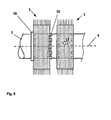
- FIG. 5 shows a schematic representation of the structure of a cleaning brush.
- a first cleaning element 1 is pushed onto the shaft 2 and held in a clamping element 18.
- the clamping element 18 is designed such that the cleaning element 1 is held against rotation.
- a coupling piece 16 is applied to the shaft 2.
- the coupling piece 16 is rotatably connected thereto via a toothing provided in the cleaning element 1.
- toothing instead of a toothing other connections such as pins are conceivable, which lead to a rotationally fixed connection of cleaning element 1 and coupling piece 16.
- a second cleaning element 1 is now pushed in the direction of the longitudinal axis 4 and in the direction of arrow 17 against the first cleaning element 1 on the shaft 2.
- the second cleaning element 1 engages in the coupling piece 16. This leads to a rotationally fixed connection of the two cleaning elements 1 via the inserted coupling piece 16.
- the coupling piece 16 is completely absorbed by the two cleaning elements 1, so in the finished assembled Condition the cleaning elements 1 abut each other without a gap.
Landscapes
- Engineering & Computer Science (AREA)
- Textile Engineering (AREA)
- Environmental & Geological Engineering (AREA)
- Brushes (AREA)
- Cleaning In General (AREA)
- Cleaning Implements For Floors, Carpets, Furniture, Walls, And The Like (AREA)
Applications Claiming Priority (1)
| Application Number | Priority Date | Filing Date | Title |
|---|---|---|---|
| CH01433/14A CH710140A1 (de) | 2014-09-23 | 2014-09-23 | Reinigungsbürste. |
Publications (2)
| Publication Number | Publication Date |
|---|---|
| EP3000352A1 true EP3000352A1 (fr) | 2016-03-30 |
| EP3000352B1 EP3000352B1 (fr) | 2020-07-22 |
Family
ID=54544867
Family Applications (1)
| Application Number | Title | Priority Date | Filing Date |
|---|---|---|---|
| EP15002708.4A Active EP3000352B1 (fr) | 2014-09-23 | 2015-09-18 | Brosse de nettoyage |
Country Status (5)
| Country | Link |
|---|---|
| US (1) | US10064481B2 (fr) |
| EP (1) | EP3000352B1 (fr) |
| CN (1) | CN105442106B (fr) |
| CH (1) | CH710140A1 (fr) |
| MX (1) | MX362968B (fr) |
Cited By (1)
| Publication number | Priority date | Publication date | Assignee | Title |
|---|---|---|---|---|
| WO2018207044A1 (fr) * | 2017-05-11 | 2018-11-15 | Graf + Cie Ag | Dispositif de nettoyage pour une garniture d'un cylindre de peignage |
Families Citing this family (3)
| Publication number | Priority date | Publication date | Assignee | Title |
|---|---|---|---|---|
| CN107116746A (zh) * | 2017-04-18 | 2017-09-01 | 安徽振达刷业有限公司 | 一种一体式毛刷及其注塑模具 |
| CN108158197A (zh) * | 2017-12-19 | 2018-06-15 | 马斌祥 | 一种沙发地毯清洁用静电除尘滚筒 |
| CH714816A1 (de) * | 2018-03-21 | 2019-09-30 | Rieter Ag Maschf | Querband für eine Bandbildungseinheit einer Karde. |
Citations (6)
| Publication number | Priority date | Publication date | Assignee | Title |
|---|---|---|---|---|
| US2864112A (en) * | 1955-04-22 | 1958-12-16 | Newark Brush Company | Street sweeper brush and holder |
| US3407425A (en) * | 1968-01-15 | 1968-10-29 | Arthur E. Drumm | Spacer for use in rotary brush assembly |
| DE4334246A1 (de) | 1993-10-08 | 1995-04-13 | Spinnereimaschinenbau Leisnig | Rotierend antreibbare Rundbürste für das Reinigen von vorzugsweise garnierten Walzen |
| EP1634783A2 (fr) * | 2004-09-13 | 2006-03-15 | Auwa Industriebürsten GmbH | Kit de montage pour la garniture d'un cylindre de travail d'une installation de lavage de voiture |
| EP1763597A1 (fr) | 2004-07-07 | 2007-03-21 | Maschinenfabrik Rieter Ag | Dispositif de debourrage pour une machine textile |
| DE102009016151A1 (de) * | 2009-04-05 | 2010-10-21 | Kratzenfabrik Mehlhorn Gmbh | Rotationsbürstenwerkzeug zur Oberflächenbearbeitung |
Family Cites Families (25)
| Publication number | Priority date | Publication date | Assignee | Title |
|---|---|---|---|---|
| US1318778A (en) * | 1919-10-14 | Planodrapi | ||
| US455729A (en) * | 1891-07-07 | Roll for napping or other machines | ||
| US1524640A (en) * | 1925-01-27 | Cylindrical or ring-shaped brush | ||
| US992175A (en) * | 1910-01-10 | 1911-05-16 | George B Dexter | Device for restoring nap to fabrics. |
| US1975567A (en) * | 1930-05-09 | 1934-10-02 | Dossmann Wilhelm | Fastening device for rotary brushes and the like |
| FR765069A (fr) * | 1932-12-06 | 1934-06-01 | Garniture de carde | |
| GB411946A (en) * | 1932-12-29 | 1934-06-21 | Emma Dossmann | Improvements in roller brushes |
| US2172433A (en) * | 1937-05-05 | 1939-09-12 | George R Churchill | Rotary brush |
| US2340069A (en) * | 1941-05-31 | 1944-01-25 | Mccarthy John William | Clothing for use in fabric brushing machines |
| GB550214A (en) * | 1942-04-16 | 1942-12-29 | John William Mccarthy | Improvements in and relating to clothing for use in fabric brushing machines |
| US2739332A (en) * | 1954-04-12 | 1956-03-27 | John C Ward | Rotary wire brushes |
| US2877481A (en) * | 1955-01-05 | 1959-03-17 | Pittsburgh Plate Glass Co | Rotary brush sections |
| US2929088A (en) * | 1955-08-16 | 1960-03-22 | Firestone Tire & Rubber Co | Roll for cleaning continuous strip material |
| GB894323A (en) * | 1958-11-27 | 1962-04-18 | Caspar Monforts Von Hobe | Improvements in textile napping machines |
| US3134123A (en) * | 1960-10-20 | 1964-05-26 | Osborn Mfg Co | Segmental rotary brush |
| US3106737A (en) * | 1961-09-05 | 1963-10-15 | Manufacturers Brush Company | Cylindrical brush |
| US3167800A (en) * | 1963-05-10 | 1965-02-02 | Louis J Mundo | Washing brushes |
| US3281882A (en) * | 1964-02-27 | 1966-11-01 | Osborn Mfg Co | Brush type rotary tools and the like |
| US3614801A (en) * | 1970-04-22 | 1971-10-26 | Tennant Co | Rotary tubular brush |
| US3851350A (en) * | 1973-08-06 | 1974-12-03 | Mfg Brush Co | Interlocking rotary brush construction |
| DE3603287A1 (de) * | 1986-02-04 | 1987-08-06 | Marta Pajtak | Walze mit elastischen borsten |
| US5083840A (en) * | 1988-04-27 | 1992-01-28 | Minnesota Mining And Manufacturing Company | Method of preparing an industrial cylinder brush arrangement for operation |
| GB0218511D0 (en) * | 2002-08-09 | 2002-09-18 | Holdsworth James & Brothers | Card clothing |
| US6974193B2 (en) * | 2002-08-13 | 2005-12-13 | Jason Incorporated | Power operated brush and method |
| CN203307495U (zh) * | 2013-05-20 | 2013-11-27 | 浙江新棉纺织有限公司 | 梳棉机的盖板针布清洁辊 |
-
2014
- 2014-09-23 CH CH01433/14A patent/CH710140A1/de not_active Application Discontinuation
-
2015
- 2015-09-18 EP EP15002708.4A patent/EP3000352B1/fr active Active
- 2015-09-22 CN CN201510605730.9A patent/CN105442106B/zh active Active
- 2015-09-22 MX MX2015013519A patent/MX362968B/es active IP Right Grant
- 2015-09-23 US US14/862,333 patent/US10064481B2/en active Active
Patent Citations (6)
| Publication number | Priority date | Publication date | Assignee | Title |
|---|---|---|---|---|
| US2864112A (en) * | 1955-04-22 | 1958-12-16 | Newark Brush Company | Street sweeper brush and holder |
| US3407425A (en) * | 1968-01-15 | 1968-10-29 | Arthur E. Drumm | Spacer for use in rotary brush assembly |
| DE4334246A1 (de) | 1993-10-08 | 1995-04-13 | Spinnereimaschinenbau Leisnig | Rotierend antreibbare Rundbürste für das Reinigen von vorzugsweise garnierten Walzen |
| EP1763597A1 (fr) | 2004-07-07 | 2007-03-21 | Maschinenfabrik Rieter Ag | Dispositif de debourrage pour une machine textile |
| EP1634783A2 (fr) * | 2004-09-13 | 2006-03-15 | Auwa Industriebürsten GmbH | Kit de montage pour la garniture d'un cylindre de travail d'une installation de lavage de voiture |
| DE102009016151A1 (de) * | 2009-04-05 | 2010-10-21 | Kratzenfabrik Mehlhorn Gmbh | Rotationsbürstenwerkzeug zur Oberflächenbearbeitung |
Cited By (1)
| Publication number | Priority date | Publication date | Assignee | Title |
|---|---|---|---|---|
| WO2018207044A1 (fr) * | 2017-05-11 | 2018-11-15 | Graf + Cie Ag | Dispositif de nettoyage pour une garniture d'un cylindre de peignage |
Also Published As
| Publication number | Publication date |
|---|---|
| US20160081464A1 (en) | 2016-03-24 |
| CN105442106B (zh) | 2020-03-20 |
| CN105442106A (zh) | 2016-03-30 |
| EP3000352B1 (fr) | 2020-07-22 |
| MX362968B (es) | 2019-02-28 |
| US10064481B2 (en) | 2018-09-04 |
| MX2015013519A (es) | 2016-07-08 |
| CH710140A1 (de) | 2016-03-31 |
Similar Documents
| Publication | Publication Date | Title |
|---|---|---|
| EP2482692B1 (fr) | Support de poils et système de support de poils pour des brosses rotatives de type rouleaux destinées à des balayeuses mécaniques | |
| EP3000352B1 (fr) | Brosse de nettoyage | |
| EP3268526B1 (fr) | Cylindre d'aiguilles et machine à tricoter circulaire | |
| EP2650414B1 (fr) | Elément de peigne pour un peigne rond d'une peigneuse | |
| DE3711558C1 (de) | Fadenliefervorrichtung fuer Strickmaschinen | |
| DE3438133A1 (de) | Aufloesewalze fuer open-end spinnmaschinen | |
| DE19829159A1 (de) | Kämmsegment für einen Rundkamm einer textilen Kämm-Maschine | |
| DE102012025176A1 (de) | Verdichter | |
| EP2561779A1 (fr) | Dispositif-infuseur pour une machine à café | |
| EP1121479A1 (fr) | Systeme pour fixer une tissu maille a deux couches sur un support | |
| EP3980195B1 (fr) | Rouleau de saupoudrage pour un dispositif de distribution | |
| EP0557478B1 (fr) | Procede servant a empecher des mailles de filer dans la gaine filtrante d'un element de drainage | |
| DE1926419A1 (de) | Putzvorrichtung fuer Streckwerke von Spinnereimaschinen | |
| DE3331347C1 (de) | Freilaufkupplung, insbes. zum Anziehen oder Lösen von Ringmuttern | |
| DE202018103126U1 (de) | Rotierbare Reinigungsbürsteneinheit und deren Verwendung | |
| DE3247298C2 (de) | Motorisch angetriebene, walzenförmige Bürste für ein Reinigungsgerät | |
| DE2901408A1 (de) | Falschdrahtzwirnkopf | |
| DE2636868A1 (de) | Spule fuer einen gekruemmten stabbreithalter, sowie damit ausgestatteter breithalter | |
| DE102007022287A1 (de) | Extrudermischer | |
| EP2277702B1 (fr) | Agencement de brosses rotatives | |
| DE102008007193A1 (de) | Abstreifwalze für eine Textilmaschine | |
| DE102010035667A1 (de) | Vorrichtung zur Vorbereitung von Borstenbündeln | |
| DE102015013123A1 (de) | Spindelschaft, Spinnhülse und Formwerkzeug | |
| DE102021128367A1 (de) | Filtereinrichtung zum Filtrieren eines suspensionsartigen Stoffgemischs | |
| DE9113140U1 (de) | Vorrichtung zur Führung eines Fadens o.dgl. |
Legal Events
| Date | Code | Title | Description |
|---|---|---|---|
| PUAI | Public reference made under article 153(3) epc to a published international application that has entered the european phase |
Free format text: ORIGINAL CODE: 0009012 |
|
| AK | Designated contracting states |
Kind code of ref document: A1 Designated state(s): AL AT BE BG CH CY CZ DE DK EE ES FI FR GB GR HR HU IE IS IT LI LT LU LV MC MK MT NL NO PL PT RO RS SE SI SK SM TR |
|
| AX | Request for extension of the european patent |
Extension state: BA ME |
|
| 17P | Request for examination filed |
Effective date: 20160914 |
|
| RBV | Designated contracting states (corrected) |
Designated state(s): AL AT BE BG CH CY CZ DE DK EE ES FI FR GB GR HR HU IE IS IT LI LT LU LV MC MK MT NL NO PL PT RO RS SE SI SK SM TR |
|
| GRAP | Despatch of communication of intention to grant a patent |
Free format text: ORIGINAL CODE: EPIDOSNIGR1 |
|
| STAA | Information on the status of an ep patent application or granted ep patent |
Free format text: STATUS: GRANT OF PATENT IS INTENDED |
|
| INTG | Intention to grant announced |
Effective date: 20200224 |
|
| GRAS | Grant fee paid |
Free format text: ORIGINAL CODE: EPIDOSNIGR3 |
|
| GRAA | (expected) grant |
Free format text: ORIGINAL CODE: 0009210 |
|
| STAA | Information on the status of an ep patent application or granted ep patent |
Free format text: STATUS: THE PATENT HAS BEEN GRANTED |
|
| AK | Designated contracting states |
Kind code of ref document: B1 Designated state(s): AL AT BE BG CH CY CZ DE DK EE ES FI FR GB GR HR HU IE IS IT LI LT LU LV MC MK MT NL NO PL PT RO RS SE SI SK SM TR |
|
| REG | Reference to a national code |
Ref country code: GB Ref legal event code: FG4D Free format text: NOT ENGLISH |
|
| REG | Reference to a national code |
Ref country code: CH Ref legal event code: EP |
|
| REG | Reference to a national code |
Ref country code: DE Ref legal event code: R096 Ref document number: 502015013046 Country of ref document: DE |
|
| REG | Reference to a national code |
Ref country code: AT Ref legal event code: REF Ref document number: 1292538 Country of ref document: AT Kind code of ref document: T Effective date: 20200815 |
|
| REG | Reference to a national code |
Ref country code: IE Ref legal event code: FG4D Free format text: LANGUAGE OF EP DOCUMENT: GERMAN |
|
| REG | Reference to a national code |
Ref country code: LT Ref legal event code: MG4D |
|
| PG25 | Lapsed in a contracting state [announced via postgrant information from national office to epo] |
Ref country code: HR Free format text: LAPSE BECAUSE OF FAILURE TO SUBMIT A TRANSLATION OF THE DESCRIPTION OR TO PAY THE FEE WITHIN THE PRESCRIBED TIME-LIMIT Effective date: 20200722 Ref country code: SE Free format text: LAPSE BECAUSE OF FAILURE TO SUBMIT A TRANSLATION OF THE DESCRIPTION OR TO PAY THE FEE WITHIN THE PRESCRIBED TIME-LIMIT Effective date: 20200722 Ref country code: FI Free format text: LAPSE BECAUSE OF FAILURE TO SUBMIT A TRANSLATION OF THE DESCRIPTION OR TO PAY THE FEE WITHIN THE PRESCRIBED TIME-LIMIT Effective date: 20200722 Ref country code: LT Free format text: LAPSE BECAUSE OF FAILURE TO SUBMIT A TRANSLATION OF THE DESCRIPTION OR TO PAY THE FEE WITHIN THE PRESCRIBED TIME-LIMIT Effective date: 20200722 Ref country code: BG Free format text: LAPSE BECAUSE OF FAILURE TO SUBMIT A TRANSLATION OF THE DESCRIPTION OR TO PAY THE FEE WITHIN THE PRESCRIBED TIME-LIMIT Effective date: 20201022 Ref country code: PT Free format text: LAPSE BECAUSE OF FAILURE TO SUBMIT A TRANSLATION OF THE DESCRIPTION OR TO PAY THE FEE WITHIN THE PRESCRIBED TIME-LIMIT Effective date: 20201123 Ref country code: ES Free format text: LAPSE BECAUSE OF FAILURE TO SUBMIT A TRANSLATION OF THE DESCRIPTION OR TO PAY THE FEE WITHIN THE PRESCRIBED TIME-LIMIT Effective date: 20200722 Ref country code: NO Free format text: LAPSE BECAUSE OF FAILURE TO SUBMIT A TRANSLATION OF THE DESCRIPTION OR TO PAY THE FEE WITHIN THE PRESCRIBED TIME-LIMIT Effective date: 20201022 Ref country code: GR Free format text: LAPSE BECAUSE OF FAILURE TO SUBMIT A TRANSLATION OF THE DESCRIPTION OR TO PAY THE FEE WITHIN THE PRESCRIBED TIME-LIMIT Effective date: 20201023 |
|
| PG25 | Lapsed in a contracting state [announced via postgrant information from national office to epo] |
Ref country code: IS Free format text: LAPSE BECAUSE OF FAILURE TO SUBMIT A TRANSLATION OF THE DESCRIPTION OR TO PAY THE FEE WITHIN THE PRESCRIBED TIME-LIMIT Effective date: 20201122 Ref country code: PL Free format text: LAPSE BECAUSE OF FAILURE TO SUBMIT A TRANSLATION OF THE DESCRIPTION OR TO PAY THE FEE WITHIN THE PRESCRIBED TIME-LIMIT Effective date: 20200722 Ref country code: RS Free format text: LAPSE BECAUSE OF FAILURE TO SUBMIT A TRANSLATION OF THE DESCRIPTION OR TO PAY THE FEE WITHIN THE PRESCRIBED TIME-LIMIT Effective date: 20200722 Ref country code: LV Free format text: LAPSE BECAUSE OF FAILURE TO SUBMIT A TRANSLATION OF THE DESCRIPTION OR TO PAY THE FEE WITHIN THE PRESCRIBED TIME-LIMIT Effective date: 20200722 |
|
| PG25 | Lapsed in a contracting state [announced via postgrant information from national office to epo] |
Ref country code: NL Free format text: LAPSE BECAUSE OF FAILURE TO SUBMIT A TRANSLATION OF THE DESCRIPTION OR TO PAY THE FEE WITHIN THE PRESCRIBED TIME-LIMIT Effective date: 20200722 |
|
| REG | Reference to a national code |
Ref country code: DE Ref legal event code: R097 Ref document number: 502015013046 Country of ref document: DE |
|
| PG25 | Lapsed in a contracting state [announced via postgrant information from national office to epo] |
Ref country code: CZ Free format text: LAPSE BECAUSE OF FAILURE TO SUBMIT A TRANSLATION OF THE DESCRIPTION OR TO PAY THE FEE WITHIN THE PRESCRIBED TIME-LIMIT Effective date: 20200722 Ref country code: DK Free format text: LAPSE BECAUSE OF FAILURE TO SUBMIT A TRANSLATION OF THE DESCRIPTION OR TO PAY THE FEE WITHIN THE PRESCRIBED TIME-LIMIT Effective date: 20200722 Ref country code: SM Free format text: LAPSE BECAUSE OF FAILURE TO SUBMIT A TRANSLATION OF THE DESCRIPTION OR TO PAY THE FEE WITHIN THE PRESCRIBED TIME-LIMIT Effective date: 20200722 Ref country code: RO Free format text: LAPSE BECAUSE OF FAILURE TO SUBMIT A TRANSLATION OF THE DESCRIPTION OR TO PAY THE FEE WITHIN THE PRESCRIBED TIME-LIMIT Effective date: 20200722 Ref country code: EE Free format text: LAPSE BECAUSE OF FAILURE TO SUBMIT A TRANSLATION OF THE DESCRIPTION OR TO PAY THE FEE WITHIN THE PRESCRIBED TIME-LIMIT Effective date: 20200722 Ref country code: MC Free format text: LAPSE BECAUSE OF FAILURE TO SUBMIT A TRANSLATION OF THE DESCRIPTION OR TO PAY THE FEE WITHIN THE PRESCRIBED TIME-LIMIT Effective date: 20200722 |
|
| REG | Reference to a national code |
Ref country code: CH Ref legal event code: PL |
|
| PLBE | No opposition filed within time limit |
Free format text: ORIGINAL CODE: 0009261 |
|
| STAA | Information on the status of an ep patent application or granted ep patent |
Free format text: STATUS: NO OPPOSITION FILED WITHIN TIME LIMIT |
|
| PG25 | Lapsed in a contracting state [announced via postgrant information from national office to epo] |
Ref country code: AL Free format text: LAPSE BECAUSE OF FAILURE TO SUBMIT A TRANSLATION OF THE DESCRIPTION OR TO PAY THE FEE WITHIN THE PRESCRIBED TIME-LIMIT Effective date: 20200722 |
|
| REG | Reference to a national code |
Ref country code: BE Ref legal event code: MM Effective date: 20200930 |
|
| GBPC | Gb: european patent ceased through non-payment of renewal fee |
Effective date: 20201022 |
|
| 26N | No opposition filed |
Effective date: 20210423 |
|
| PG25 | Lapsed in a contracting state [announced via postgrant information from national office to epo] |
Ref country code: SK Free format text: LAPSE BECAUSE OF FAILURE TO SUBMIT A TRANSLATION OF THE DESCRIPTION OR TO PAY THE FEE WITHIN THE PRESCRIBED TIME-LIMIT Effective date: 20200722 Ref country code: LU Free format text: LAPSE BECAUSE OF NON-PAYMENT OF DUE FEES Effective date: 20200918 |
|
| PG25 | Lapsed in a contracting state [announced via postgrant information from national office to epo] |
Ref country code: FR Free format text: LAPSE BECAUSE OF NON-PAYMENT OF DUE FEES Effective date: 20200922 |
|
| PG25 | Lapsed in a contracting state [announced via postgrant information from national office to epo] |
Ref country code: SI Free format text: LAPSE BECAUSE OF FAILURE TO SUBMIT A TRANSLATION OF THE DESCRIPTION OR TO PAY THE FEE WITHIN THE PRESCRIBED TIME-LIMIT Effective date: 20200722 Ref country code: GB Free format text: LAPSE BECAUSE OF NON-PAYMENT OF DUE FEES Effective date: 20201022 Ref country code: LI Free format text: LAPSE BECAUSE OF NON-PAYMENT OF DUE FEES Effective date: 20200930 Ref country code: IE Free format text: LAPSE BECAUSE OF NON-PAYMENT OF DUE FEES Effective date: 20200918 Ref country code: CH Free format text: LAPSE BECAUSE OF NON-PAYMENT OF DUE FEES Effective date: 20200930 Ref country code: BE Free format text: LAPSE BECAUSE OF NON-PAYMENT OF DUE FEES Effective date: 20200930 |
|
| REG | Reference to a national code |
Ref country code: NL Ref legal event code: MP Effective date: 20200722 |
|
| REG | Reference to a national code |
Ref country code: AT Ref legal event code: MM01 Ref document number: 1292538 Country of ref document: AT Kind code of ref document: T Effective date: 20200918 |
|
| PG25 | Lapsed in a contracting state [announced via postgrant information from national office to epo] |
Ref country code: AT Free format text: LAPSE BECAUSE OF NON-PAYMENT OF DUE FEES Effective date: 20200918 |
|
| PG25 | Lapsed in a contracting state [announced via postgrant information from national office to epo] |
Ref country code: MT Free format text: LAPSE BECAUSE OF FAILURE TO SUBMIT A TRANSLATION OF THE DESCRIPTION OR TO PAY THE FEE WITHIN THE PRESCRIBED TIME-LIMIT Effective date: 20200722 Ref country code: CY Free format text: LAPSE BECAUSE OF FAILURE TO SUBMIT A TRANSLATION OF THE DESCRIPTION OR TO PAY THE FEE WITHIN THE PRESCRIBED TIME-LIMIT Effective date: 20200722 |
|
| PG25 | Lapsed in a contracting state [announced via postgrant information from national office to epo] |
Ref country code: MK Free format text: LAPSE BECAUSE OF FAILURE TO SUBMIT A TRANSLATION OF THE DESCRIPTION OR TO PAY THE FEE WITHIN THE PRESCRIBED TIME-LIMIT Effective date: 20200722 |
|
| P01 | Opt-out of the competence of the unified patent court (upc) registered |
Effective date: 20230519 |
|
| PGFP | Annual fee paid to national office [announced via postgrant information from national office to epo] |
Ref country code: DE Payment date: 20250919 Year of fee payment: 11 |
|
| PGFP | Annual fee paid to national office [announced via postgrant information from national office to epo] |
Ref country code: TR Payment date: 20250911 Year of fee payment: 11 |
|
| PGFP | Annual fee paid to national office [announced via postgrant information from national office to epo] |
Ref country code: IT Payment date: 20250930 Year of fee payment: 11 |