EP3000149B1 - Mehrlagige schichtanordnung für einen festkörperelektrolyt - Google Patents
Mehrlagige schichtanordnung für einen festkörperelektrolyt Download PDFInfo
- Publication number
- EP3000149B1 EP3000149B1 EP14728826.0A EP14728826A EP3000149B1 EP 3000149 B1 EP3000149 B1 EP 3000149B1 EP 14728826 A EP14728826 A EP 14728826A EP 3000149 B1 EP3000149 B1 EP 3000149B1
- Authority
- EP
- European Patent Office
- Prior art keywords
- layer
- electrolyte
- layers
- cathode
- oxide
- Prior art date
- Legal status (The legal status is an assumption and is not a legal conclusion. Google has not performed a legal analysis and makes no representation as to the accuracy of the status listed.)
- Not-in-force
Links
Images

Classifications
-
- H—ELECTRICITY
- H01—ELECTRIC ELEMENTS
- H01M—PROCESSES OR MEANS, e.g. BATTERIES, FOR THE DIRECT CONVERSION OF CHEMICAL ENERGY INTO ELECTRICAL ENERGY
- H01M8/00—Fuel cells; Manufacture thereof
- H01M8/10—Fuel cells with solid electrolytes
- H01M8/1004—Fuel cells with solid electrolytes characterised by membrane-electrode assemblies [MEA]
-
- H—ELECTRICITY
- H01—ELECTRIC ELEMENTS
- H01M—PROCESSES OR MEANS, e.g. BATTERIES, FOR THE DIRECT CONVERSION OF CHEMICAL ENERGY INTO ELECTRICAL ENERGY
- H01M8/00—Fuel cells; Manufacture thereof
- H01M8/10—Fuel cells with solid electrolytes
- H01M8/12—Fuel cells with solid electrolytes operating at high temperature, e.g. with stabilised ZrO2 electrolyte
- H01M8/1213—Fuel cells with solid electrolytes operating at high temperature, e.g. with stabilised ZrO2 electrolyte characterised by the electrode/electrolyte combination or the supporting material
-
- H—ELECTRICITY
- H01—ELECTRIC ELEMENTS
- H01M—PROCESSES OR MEANS, e.g. BATTERIES, FOR THE DIRECT CONVERSION OF CHEMICAL ENERGY INTO ELECTRICAL ENERGY
- H01M8/00—Fuel cells; Manufacture thereof
- H01M8/10—Fuel cells with solid electrolytes
- H01M8/12—Fuel cells with solid electrolytes operating at high temperature, e.g. with stabilised ZrO2 electrolyte
- H01M8/124—Fuel cells with solid electrolytes operating at high temperature, e.g. with stabilised ZrO2 electrolyte characterised by the process of manufacturing or by the material of the electrolyte
- H01M8/1246—Fuel cells with solid electrolytes operating at high temperature, e.g. with stabilised ZrO2 electrolyte characterised by the process of manufacturing or by the material of the electrolyte the electrolyte consisting of oxides
-
- H—ELECTRICITY
- H01—ELECTRIC ELEMENTS
- H01M—PROCESSES OR MEANS, e.g. BATTERIES, FOR THE DIRECT CONVERSION OF CHEMICAL ENERGY INTO ELECTRICAL ENERGY
- H01M8/00—Fuel cells; Manufacture thereof
- H01M8/10—Fuel cells with solid electrolytes
- H01M8/12—Fuel cells with solid electrolytes operating at high temperature, e.g. with stabilised ZrO2 electrolyte
- H01M2008/1293—Fuel cells with solid oxide electrolytes
-
- H—ELECTRICITY
- H01—ELECTRIC ELEMENTS
- H01M—PROCESSES OR MEANS, e.g. BATTERIES, FOR THE DIRECT CONVERSION OF CHEMICAL ENERGY INTO ELECTRICAL ENERGY
- H01M2300/00—Electrolytes
- H01M2300/0017—Non-aqueous electrolytes
- H01M2300/0065—Solid electrolytes
- H01M2300/0068—Solid electrolytes inorganic
- H01M2300/0071—Oxides
- H01M2300/0074—Ion conductive at high temperature
- H01M2300/0077—Ion conductive at high temperature based on zirconium oxide
-
- H—ELECTRICITY
- H01—ELECTRIC ELEMENTS
- H01M—PROCESSES OR MEANS, e.g. BATTERIES, FOR THE DIRECT CONVERSION OF CHEMICAL ENERGY INTO ELECTRICAL ENERGY
- H01M2300/00—Electrolytes
- H01M2300/0088—Composites
- H01M2300/0094—Composites in the form of layered products, e.g. coatings
-
- H—ELECTRICITY
- H01—ELECTRIC ELEMENTS
- H01M—PROCESSES OR MEANS, e.g. BATTERIES, FOR THE DIRECT CONVERSION OF CHEMICAL ENERGY INTO ELECTRICAL ENERGY
- H01M8/00—Fuel cells; Manufacture thereof
- H01M8/10—Fuel cells with solid electrolytes
- H01M8/12—Fuel cells with solid electrolytes operating at high temperature, e.g. with stabilised ZrO2 electrolyte
- H01M8/124—Fuel cells with solid electrolytes operating at high temperature, e.g. with stabilised ZrO2 electrolyte characterised by the process of manufacturing or by the material of the electrolyte
- H01M8/1246—Fuel cells with solid electrolytes operating at high temperature, e.g. with stabilised ZrO2 electrolyte characterised by the process of manufacturing or by the material of the electrolyte the electrolyte consisting of oxides
- H01M8/1253—Fuel cells with solid electrolytes operating at high temperature, e.g. with stabilised ZrO2 electrolyte characterised by the process of manufacturing or by the material of the electrolyte the electrolyte consisting of oxides the electrolyte containing zirconium oxide
-
- Y—GENERAL TAGGING OF NEW TECHNOLOGICAL DEVELOPMENTS; GENERAL TAGGING OF CROSS-SECTIONAL TECHNOLOGIES SPANNING OVER SEVERAL SECTIONS OF THE IPC; TECHNICAL SUBJECTS COVERED BY FORMER USPC CROSS-REFERENCE ART COLLECTIONS [XRACs] AND DIGESTS
- Y02—TECHNOLOGIES OR APPLICATIONS FOR MITIGATION OR ADAPTATION AGAINST CLIMATE CHANGE
- Y02E—REDUCTION OF GREENHOUSE GAS [GHG] EMISSIONS, RELATED TO ENERGY GENERATION, TRANSMISSION OR DISTRIBUTION
- Y02E60/00—Enabling technologies; Technologies with a potential or indirect contribution to GHG emissions mitigation
- Y02E60/30—Hydrogen technology
- Y02E60/50—Fuel cells
-
- Y—GENERAL TAGGING OF NEW TECHNOLOGICAL DEVELOPMENTS; GENERAL TAGGING OF CROSS-SECTIONAL TECHNOLOGIES SPANNING OVER SEVERAL SECTIONS OF THE IPC; TECHNICAL SUBJECTS COVERED BY FORMER USPC CROSS-REFERENCE ART COLLECTIONS [XRACs] AND DIGESTS
- Y02—TECHNOLOGIES OR APPLICATIONS FOR MITIGATION OR ADAPTATION AGAINST CLIMATE CHANGE
- Y02P—CLIMATE CHANGE MITIGATION TECHNOLOGIES IN THE PRODUCTION OR PROCESSING OF GOODS
- Y02P70/00—Climate change mitigation technologies in the production process for final industrial or consumer products
- Y02P70/50—Manufacturing or production processes characterised by the final manufactured product
Definitions
- the invention relates to a cathode-electrolyte anode unit for an electrochemical functional device, in particular for a high-temperature fuel cell, and a manufacturing method thereof.
- Solid oxide fuel cells allow direct conversion of chemical energy into electrical energy.
- the electrochemically active cell of an SOFC consists of a so-called cathode-electrolyte-anode unit (single cell), in which a gas-tight solid electrolyte between a gas-permeable anode and a gas-permeable cathode is arranged.
- the solid electrolyte usually consists of a solid ceramic material of metal oxide, which conducts oxygen ions, but not electrons.
- the anode During operation of an SOFC, the anode is supplied with fuel (for example hydrogen or conventional hydrocarbons, such as methane, natural gas, biogas, etc.) and is catalytically oxidized there with the emission of electrons.
- fuel for example hydrogen or conventional hydrocarbons, such as methane, natural gas, biogas, etc.
- the electrons are derived from the fuel cell and flow via an electrical load to the cathode.
- an oxidant eg, oxygen or air
- the electrical circuit closes as the oxygen ions flow across the electrolyte to the anode and react with the fuel at the appropriate interfaces.
- the electrolyte is the mechanically-bearing cell component ("Electrolyte Supported Cell", ESC).
- the layer thickness of the electrolyte here is relatively large, about 100-150 microns and usually consists of yttria (YSZ) or scandium (ScSZ) stabilized zirconia.
- YSZ yttria
- ScSZ scandium
- these fuel cells must be operated at a relatively high operating temperature of about 850-1000 ° C. This high operating temperature leads to high demands on the materials used.
- anode- and cathode-supported SOFC systems in which a relatively thick (at least about 200 microns) mechanically supporting ceramic anode or cathode substrate with a thin Electrochemically active anode or cathode functional layer is connected. Since the electrolyte layer no longer has to perform a mechanically supporting role, it can be made relatively thin and the operating temperature can be correspondingly reduced due to the lower ohmic resistance.
- SOFC thin film systems based on a metallic carrier substrate so-called metal-supported SOFC ("metal-supported cell", MSC) have been developed as the latest generation.
- MSC metal-supported SOFC
- These metallic-ceramic composite systems show advantages over purely ceramic thin-film systems in terms of manufacturing costs, thermal and redox cyclability and mechanical stability and can also be operated at an even lower operating temperature of about 600 ° C to 800 ° C due to their thin-film electrolyte. Due to their specific advantages, they are particularly suitable for mobile applications, such as for the electrical supply of passenger cars or utility vehicles (APU-Auxiliary Power Unit).
- An exemplary MSC known from the state of the art consists of a porous carrier substrate which is about 1 mm thick, and thus permeable to gas, onto which a 60-70 ⁇ m thick cathode-electrolyte anode unit, which is actually electrochemically active layer arrangement, is arranged.
- the anode faces the carrier substrate and, in the sequence of the layer assembly, is closer to the metal substrate than the cathode.
- Known ceramic thin-film electrolyte fabrication methods include, in addition to wet-ceramic processes such as wet powder coating or screen printing, which sinter the electrolyte for required gas tightness (using yttria-stabilized zirconia (YSZ) at about 1400 ° C.), coating methods such as physical vapor deposition (PVD). Physical Vapor Deposition).
- wet-ceramic processes such as wet powder coating or screen printing, which sinter the electrolyte for required gas tightness (using yttria-stabilized zirconia (YSZ) at about 1400 ° C.), coating methods such as physical vapor deposition (PVD). Physical Vapor Deposition).
- Coating methods such as PVD have considerable advantages due to the lower process temperature, in particular for metal substrate-supported SOFCs. While coating methods are typically used to modify the properties of predominantly smooth surfaces, the challenge of using PVD for SOFC is to deposit a gas-tight layer as thin as possible on a porous substrate such as the anode.
- the layer growth and the microstructure (crucial for the gas permeability) of the applied electrolyte layer is significantly influenced by the surface structure of the substrate (porosity, surface roughness, cracks, defects, ).
- electrode-supported SOFCs have been able to realize gas-tight electrolytes with a layer thickness of less than 3 ⁇ m by means of PVD ( DE 10 2007 015 358 A1 ).
- the thin layer thickness of the electrolyte is achieved by pre-treating the surface of the anode substrate, which reduces the porosity, before the PVD coating process.
- near-surface pores of the anode of a mixture of nickel oxide (NiO) and with 8 mol% yttria fully stabilized zirconia (8YSZ) can be closed by a vacuum slurry applied YSZ suspension, whereby after sintering a sufficiently smooth surface structure of the anode substrate is provided an electrolyte with a dense structure can be deposited ( N. Jordan-Escalona, Production of High Temperature Fuel Cells via Physical Vapor Deposition, Dissertation, Univ. Bochum 2008 ).
- the necessary gas permeability of the anode occurs during the first operation of the fuel cell when the NiO in the anode is reduced to metallic Ni, thereby increasing the porosity of the anode to about 20% to 30%.
- an embodiment of the electrolyte of a multilayer composite of gadolinium-doped cerium oxide (CGO), YSZ and CGO is known ( DE 10 2007 015 358 A1 ).
- the carrier for the anode is a powder metallurgically produced carrier substrate based on an iron-chromium alloy, wherein there is still a diffusion barrier layer made of CGO between the metal substrate and the anode.
- the electrolyte is prepared from a metallic ZrY sputtering target while supplying oxygen as a reactive gas. Due to the layer growth, the electrolyte has a columnar structure, wherein individual stems can traverse the entire thickness of the electrolyte and form spaces along the grain boundaries where gas can diffuse through. In order to achieve sufficient gas tightness, therefore, a corresponding thickness of the electrolyte is required.
- Hybrid processes are known in which the coating process is followed by a thermal treatment step.
- EP 2 083 466 A1 Such an example can be found in EP 2 083 466 A1 in which the electrolyte applied by means of a sputtering method is compacted in a subsequent sintering process step.
- a first layer of an oxide sputtering target for example 8YSZ
- HF radio frequency
- a reactive sputtering process DC or HF
- This anode-electrode assembly is then subjected to a sintering process at about 1400 ° C for about 6 hours before a cathode layer is applied in a final step.
- the disadvantage is that two systems with two different sputtering targets are needed and a more expensive and time-consuming sintering process step at high temperatures is required to consolidate the electrolyte layer. Due to the high process temperature, this method is also not suitable for MSC.
- EP 1 513 623 B1 Another approach for producing a gas-impermeable, extremely thin electrolyte layer, in which a coating process is combined with a subsequent heat treatment step, is disclosed in US Pat EP 1 513 623 B1 disclosed.
- EP 1 513 623 B1 For example, a fine-pored aluminum substrate (pore diameter up to 200 nm) is coated by a DC sputtering method using a yttrium-zirconium (YZ) sputtering target, then the oxidized YZ is oxidized to YSZ in an oxidizing atmosphere at about 300 ° C - 400 ° C Forming a uniform film subjected to a final heat treatment step at about 700 ° C.
- YZ yttrium-zirconium
- WO 2007/045111 A1 WO 02/17420 A1 or WO 2005/057685
- WO97 / 41612 describes a cathode-electrolyte-anode unit for a high-temperature fuel cell, comprising a multilayered solid electrolyte disposed between a porous anode and a porous cathode, wherein the solid electrolyte is produced by a physical vapor deposition method and has a layered structure of at least a first layer and at least a second layer , It exists in particular for MSC further development needs of the electrolyte.
- an electrochemical functional device such as an SOFC
- high oxygen ion conductivity and low electron conductivity at operating temperature chemical and mechanical stability in the process gas atmosphere used (air or fuel gas atmosphere), good adhesive properties with adjacent functional layers and sufficient gas tightness, to separate the process gas at the anode side (fuel gas) from the process gas at the cathode side (air).
- the present invention has for its object to provide a low-cost cathode-electrolyte anode unit for use in an electrochemical functional device, in particular in a high-temperature fuel cell, in which the electrolyte meets the above-mentioned requirements and has the lowest possible ohmic resistance.
- the method for producing such a cathode-electrolyte anode unit should be particularly suitable for an MSC.
- a cathode-electrolyte anode unit in which the solid-state electrolyte arranged between the cathode and the anode is designed in multiple layers and is produced by means of physical vapor deposition.
- Physical vapor deposition includes, in particular, sputtering (cathode sputtering), reactive sputtering (reactive sputtering), electron beam (Vapor Deposition) vapor deposition, pulsed laser deposition, or comparable coating processes or a combination of these coating processes.
- the solid electrolyte has a layered structure at least one first layer and at least one second layer, wherein the second layer has a higher oxygen content than the first Layer and the two layers with the exception of oxygen substantially to trace elements have the same composition.
- the two layers therefore differ primarily in their oxygen content.
- the first layer with lower oxygen content may be applied metallically
- the second layer with higher oxygen content may be applied oxide ceramic.
- metallic applied means the deposition of a metallic compound which has previously been converted into the gas phase (for example by means of a sputtering process), deposited under oxide-ceramic deposition of an oxide of this metallic compound.
- the metal oxide can be deposited, for example, using a (sputtering) target consisting of the metal oxide or by using a metallic target with the supply of oxygen as a reactive gas (reactive sputtering). Due to the process, for example, due to residual oxygen in the coating system, some oxygen can accumulate in the layer applied to metal, the metal-deposited layer must therefore not be purely metallic and may have non-metallic phases.
- the metallically applied layer has a significantly lower oxygen content than the oxide-ceramic layer applied.
- the first layer is thus formed substoichiometric.
- substoichiometric is meant that, upon deposition of the corresponding layer, oxygen incorporation is less than necessary to achieve a stoichiometric ratio in the deposited layer.
- the inventive solution is based on the idea that a metallically deposited layer can be deposited significantly more compact and dense in an advantageous manner due to the lower melting temperature of the metal compared to the corresponding metal oxide under otherwise identical process conditions as an oxide ceramic layer of the associated metal oxide.
- the stems in the metallically deposited layer are typically smaller than the stems in the corresponding oxide-ceramic deposited layer.
- the electrolyte Since the electrolyte is not subjected to a subsequent sintering process, the shape and the preferred orientation of the crystallites in the growth direction remain. As a rule, this has a positive effect on the oxygen ion conductivity of the electrolyte.
- the metallically deposited substoichiometric layer is not initially or extremely low oxygen ion conductive, but the oxygen ion conductivity of the electrolyte increases significantly when the electrolyte in air or oxygen-containing atmosphere, for example, during the first minutes in the first operation of the cathode-electrolyte-anode unit , Is paged and store oxygen ions in the metal deposited layer (s).
- the chemical composition of the individual layers of the electrolyte is then essentially the same, but structural differences, for example in the crystal system, in which the crystallites of the initially metallically deposited substoichiometric or oxide-ceramic layers are possibly crystallized differently, may continue to exist. Due to the oxygen storage, an increase in volume of the metallically applied layer with originally low oxygen content takes place, as a result of which the metallically applied layer is additionally compacted and any intermediate spaces can be reduced. Due to the comparable composition to trace elements, the adjacent layers of the electrolyte are chemically resistant to each other and have a comparable coefficient of thermal expansion.
- the electrolyte has two layers, a first layer having a lower oxygen content, which is preferably applied metallically, and a second layer having a higher oxygen content, which is preferably applied by oxide ceramics, with the exception of the oxygen content and any impurities or trace elements chemical composition of the two layers does not differ.
- Electrode material may be provided between electrolyte and electrode at least one further functional layer such as a diffusion barrier layer of CGO.
- the lower oxygen content metal layer is applied as a topcoat to the higher oxygen content oxide ceramic layer.
- the change between the layers with different oxygen content is repeated several times, the electrolyte then consists of a layer system of at least three intermediate layers, wherein first, metallically deposited layers with lower oxygen content and second, oxide ceramic applied layers higher oxygen content in an alternating manner are arranged one above the other.
- the composition of the individual oxide-ceramic or metallically applied layer (s) is preferably the same.
- the sequence of the layer arrangement therefore results in a higher oxygen content intermediate layer, lower oxygen content intermediate layer, higher oxygen content (or oxide ceramic / metallic / oxide ceramic applied) or lower oxygen intermediate layer, higher oxygen content intermediate layer, lower intermediate layer Oxygen content (or metallic / oxide ceramic / metallic applied).
- the multilayered electrolyte starting from a total of 4 intermediate layers (ie, in an alternating arrangement, a total of 2 oxide ceramic deposited layers with higher oxygen content and 2 metallically deposited layers with lower oxygen content ) to a total of 50 intermediate layers (ie, in total arrangement, a total of 25 oxide-ceramic layers with higher oxygen content and 25 metallic layers with lower oxygen content).
- a minimum thickness of an intermediate layer (applied with metallic or oxide ceramic) of about 200 nm is advantageous.
- the layer thickness of the metallically deposited intermediate layer with a lower oxygen content should not exceed 800 nm, in particular 500 nm, since an increase in volume takes place due to the later oxygen deposition and thus there is a danger of the intermediate layer spalling or flaking off. If the leak rate remains the same, the layer thickness can therefore be reduced by using the multilayered electrolyte according to the invention, and thus the ohmic resistance can be reduced.
- Some oxygen may be incorporated in the intermediate layers deposited in metal, but the oxygen content is substoichiometric and significantly lower than in the intermediate layer applied by means of oxide ceramic.
- a significant advantage of the invention is that an expensive, energy-consuming and time-consuming sintering process at high temperatures can be avoided for the production of the multilayer electrolyte.
- a physical vapor deposition method is used as the coating method.
- the electrolyte material is thereby transferred into the gas phase and led to the substrate to be coated, where it condenses.
- a layer with a lower oxygen content and a layer with a higher oxygen content are applied on top of one another on a porous substrate, such as the electrode or optionally another functional layer, if a functional layer is provided between the electrode and the electrolyte.
- Sputter deposition methods such as DC sputtering, RF sputtering, ion beam sputtering, magnetron sputtering or reactive sputtering may be mentioned as coating methods for the invention.
- Particularly advantageous is so-called hollow cathode gas flow sputtering (gas flow sputtering), a special Sputterdepositions vide in which solid material is removed by sputtering in a hollow cathode glow discharge and by means of a flowing through the hollow cathode working gas, usually argon, located outside the hollow cathode Substrate is transported, where it deposits as a layer.
- Fig. 4 shows a schematic diagram of this method.
- the sputtering target 11 has the shape of a hollow cathode, usually in the form of two parallel rectangular plates or as a short tube, and is flowed through by the working gas 13, which flows from a rear opening 14 of the hollow cathode and emanates at a front opening 15 while the atomized Cathode material transported.
- the hollow cathode is cooled by the cooling 12.
- the target is atomized by working gas ions from the glow discharge, wherein the geometry of the hollow cathode reinforcing acts for the glow discharge.
- the glow discharge is ignited by the source voltage 16.
- the typical working pressure is 0.2 - 0.8 mbar. Due to the comparatively high process pressure, the high-energy plasma particles lose most of their energy on the way to the substrate, whereby low-stress layers can be generated.
- Oxide layers can be produced in a reactive process.
- oxygen 17 is supplied as a reactive gas at the hollow cathode mouth, where the mixture of the working gas with the atomized cathode material flows out of the hollow cathode.
- the reactive gas can not penetrate to the target surface, whereby plasma instabilities or rate reduction, as often occurs in reactive magnetron sputtering avoided. Since no magnetic field is required, the target removal takes place uniformly and one can work with very high power density, which benefits a high coating rate.
- a particular advantage of the hollow cathode gas flow sputtering in terms of the present invention is that the change between metallic and oxide ceramic applied layers during the coating process can be done simply by switching on or off the supply of oxygen as a reactive gas with otherwise constant parameters and the multilayer Electrolytic process can be produced successively and without interruption in a system without the sample between the coatings cooled or the coating chamber would have to be opened. It can thereby achieve a very good contact and adhesion between the individual layers. Due to residual oxygen in the system, some oxygen can also be deposited in the layer applied in metallic form, and the layer applied in metallic form therefore does not have to be purely metallic and may have non-metallic phases. However, it has a significantly lower oxygen content than the oxide-ceramic applied layer.
- a bias voltage 18 between the anode and the substrate holder 19 can be applied to the substrate in order to increase the energy input of the working gas ions onto the substrate and to densify the deposited layer.
- the substrate holder 19 In order to coat larger areas, the substrate holder 19 must be moved with the sample to be coated 21 in front of the source. This can be done both by a pendulum motion as well as by a slow pass of the substrate holder before the source.
- the substrate temperature, the working gas flow, the reactive gas flow and the distance from the source front to the substrate surface play a role in the coating rate and the deposited layer structure.
- a device for hollow cathode gas flow sputtering is used, for example, in US Pat EP1520290 B1 described.
- the cathode-electrolyte anode unit of the present invention is applicable to anode- and cathode-assisted SOFCs, especially for MSC, where the cathode-electrolyte-anode unit is deposited and supported on a metallic carrier substrate. But it can also be used for example for an electrolyzer or in membrane technology for electrochemical gas separation.
- the metallic carrier substrate of the MSC is respectively according to AT 008 975 U1 powder metallurgically produced and consists of a ferritic iron-chromium alloy (Fe> 50 wt.% And 15 to 35 wt.% Cr) with an additional mixed oxide content (0.01-2 wt%, the mixed oxides preferably from the group Y, Sc , Rare earth metals and / or from the group Ti, Al, Cr originate) and a porosity of 30-60%.
- a diffusion barrier layer made of CGO is applied by means of PVD to this porous metal substrate which acts as a support in order to prevent interdiffusion between the metal substrate and the subsequent anode.
- the anode is designed as a multi-layer graded anode layer composite of Ni-8YSZ cermet with a thickness of about 30 to 50 microns and prepared via a wet ceramic route (screen printing) and then sintered at about 1200 ° C for 5 h in a reducing atmosphere.
- the generation of the electrolyte layers is effected by vapor deposition in a hollow cathode gas flow sputtering plant, wherein a metallic ZrY sputtering target (Zr 85.2 at%, Y 14.8%) is used.
- the metallic target is commercially available, for example, from MaTecK GmbH or Sindlhauser Materials GmbH. Before the actual coating is the Substrate cleaned in an ultrasonic bath with liquid cleaning agents.
- the coating process chamber is evacuated (chamber volume about 200 l, pumping speed of the pumping station 1000 m 3 / h) and the substrate slowly (max 20 K per minute) heated to about 500 ° C and then with the aid of an argon plasma (generated by applying a medium-frequency DC pulse bias voltage with nominal bias voltage> 100 V, 200 kHz and 1 ⁇ s counterpulse duration), whereby a process pressure of approximately 0.1 mbar is present at a volumetric flow of Ar of approximately 400 sccm. After this "fine ion cleaning", the actual coating process begins.
- the parameters shown below refer to a gas flow sputtering source with a length of 250 mm and must be adapted for other source sizes, eg linear scaled.
- Argon is used as the process gas at a volume flow of about 5000 sccm (formation of a hollow cathode discharge at a given source length and a process pressure of about 0.5 mbar), oxygen is used as reactive gas at a volume flow of about 60 sccm.
- the source voltage between the cathode and anode is about 330 V and it is thereby converted a power of about 5000 W in the plasma.
- a nominal medium frequency bias voltage of about 30-150 V is set between substrate (sample) and cathode (200 kHz, 1 ⁇ s count pulse duration) (the magnitude of the nominal bias voltage depends, among other things, on the desired density of the sputtering layer) Execution of the present substrate as well as the distance from substrate to source front (here approx. 40 mm) dependent and must be adjusted by the specialist to the respective situation).
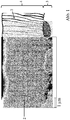
- Example 1 ( Fig. 2 ) an approximately 4 micron thick electrolyte was produced, wherein the first 3.5 microns were deposited with the supply of oxygen and an approximately 0.5 micron thick cover layer was applied without the supply of oxygen as a reactive gas.
- the electrolyte thus comprises a 3.5 ⁇ m layer with a higher oxygen content and a 0.5 ⁇ m thick cover layer with a lower oxygen content.
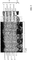
- Example 2 ( Fig. 3 ) has an electrolyte layer composite with a total of 8 intermediate layers, wherein alternately, starting with a metallically applied layer, each having an approximately 0.5 micron thick intermediate layer without Reactive gas and an approximately 0.5 micron thick intermediate layer were applied with the supply of reactive gas.
- a 20 to 60 microns thick porous cathode of lanthanum-strontium-cobalt-iron oxide (LSCF, (La 0.6 Sr 0.4 Co 0.8 Fe 0.2 ) O 3- ⁇ ) is printed by screen printing method, where before the screen printing, if necessary, the sample again a plasma treatment can be subjected. Activation of the cathode occurs in situ during the first hours of operation of the cell. In the in the Fig. 1-3 Examples shown missing in each case a CGO protective layer or the cathode.
- the multilayer structure of the electrolyte can be seen.
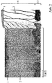
- the columnar structure of the electrolyte which is known from the prior art example in Fig. 1 can extend over the entire thickness of the electrolyte is interrupted and limited to the thickness of an intermediate layer.
- the crystallites of the metallic and oxide-ceramic deposited layer differ in shape and in the formed crystal system. While the individual stems of the oxide-ceramic deposited layer form a tetragonal or cubic crystal system typical for 8YSZ and are preferably arranged in the growth direction in columnar form, the crystallites of the metallized layer are smaller and, due to the lack of oxygen atoms, usually crystallize out in other crystal systems.
- a tetragonal or cubic crystal system sets in by the incorporation of oxygen in the metallic layer.
- a gas-tight electrolyte with a thickness of 4 ⁇ m could be produced.
- the electrolyte in Example 1 ( Fig. 2 ) has a leak rate of 7.6 10 -4 hPa dm 3 s -1 cm -2
- the electrolyte has no other elements than yttrium, zirconium and oxygen.
Landscapes
- Engineering & Computer Science (AREA)
- Manufacturing & Machinery (AREA)
- Life Sciences & Earth Sciences (AREA)
- Sustainable Development (AREA)
- Sustainable Energy (AREA)
- Chemical & Material Sciences (AREA)
- Chemical Kinetics & Catalysis (AREA)
- Electrochemistry (AREA)
- General Chemical & Material Sciences (AREA)
- Fuel Cell (AREA)
- Inert Electrodes (AREA)
- Conductive Materials (AREA)
Applications Claiming Priority (2)
| Application Number | Priority Date | Filing Date | Title |
|---|---|---|---|
| DE102013008472.5A DE102013008472A1 (de) | 2013-05-21 | 2013-05-21 | Mehrlagige Schichtanordnung für einen Festkörperelektrolyt |
| PCT/EP2014/001352 WO2014187559A1 (de) | 2013-05-21 | 2014-05-20 | Mehrlagige schichtanordnung für einen festkörperelektrolyt |
Publications (2)
| Publication Number | Publication Date |
|---|---|
| EP3000149A1 EP3000149A1 (de) | 2016-03-30 |
| EP3000149B1 true EP3000149B1 (de) | 2017-05-10 |
Family
ID=50897525
Family Applications (1)
| Application Number | Title | Priority Date | Filing Date |
|---|---|---|---|
| EP14728826.0A Not-in-force EP3000149B1 (de) | 2013-05-21 | 2014-05-20 | Mehrlagige schichtanordnung für einen festkörperelektrolyt |
Country Status (10)
| Country | Link |
|---|---|
| US (1) | US10312540B2 (enExample) |
| EP (1) | EP3000149B1 (enExample) |
| JP (1) | JP6600300B2 (enExample) |
| KR (1) | KR20160010465A (enExample) |
| CN (1) | CN105493327B (enExample) |
| CA (1) | CA2911454A1 (enExample) |
| DE (1) | DE102013008472A1 (enExample) |
| DK (1) | DK3000149T3 (enExample) |
| TW (1) | TWI634696B (enExample) |
| WO (1) | WO2014187559A1 (enExample) |
Families Citing this family (5)
| Publication number | Priority date | Publication date | Assignee | Title |
|---|---|---|---|---|
| JP6014807B2 (ja) | 2014-11-20 | 2016-10-26 | 株式会社プラズマイオンアシスト | 燃料電池用セパレータ又は燃料電池用集電部材、及びその製造方法 |
| CN105762391B (zh) * | 2016-04-15 | 2019-01-08 | 暨南大学 | 组件组成一体化的质子导体低温固体氧化物电池及其制备 |
| BR112021004708A2 (pt) * | 2018-09-12 | 2021-06-22 | Gelion Technologies Pty Ltd | bateria com agente sequestrante de halogênio, uso de um hsa polimérico, uso de um agente sequestrante de halogênio polimérico (hsa) que é um polímero e método de produção de uma bateria |
| US10930844B2 (en) | 2018-10-11 | 2021-02-23 | International Business Machines Corporation | Three-terminal oxygen intercalation neuromorphic devices |
| KR20210076688A (ko) | 2019-12-16 | 2021-06-24 | 삼성전자주식회사 | 복합 고체전해질, 이를 포함하는 전기화학 셀, 및 상기 복합 고체전해질의 제조방법 |
Family Cites Families (27)
| Publication number | Priority date | Publication date | Assignee | Title |
|---|---|---|---|---|
| US5171645A (en) * | 1991-01-08 | 1992-12-15 | Gas Research Institute, Inc. | Zirconia-bismuth oxide graded electrolyte |
| WO1997041612A1 (en) * | 1996-05-01 | 1997-11-06 | Gas Research Institute, Inc. | Stable high conductivity functionally gradient compositionally layered solid state electrolytes and membranes |
| JP3843766B2 (ja) | 2000-07-04 | 2006-11-08 | 日産自動車株式会社 | 固体電解質型燃料電池 |
| US6558831B1 (en) | 2000-08-18 | 2003-05-06 | Hybrid Power Generation Systems, Llc | Integrated SOFC |
| JP4840718B2 (ja) * | 2001-08-14 | 2011-12-21 | 日産自動車株式会社 | 固体酸化物形燃料電池 |
| JP2003142123A (ja) * | 2001-11-05 | 2003-05-16 | Nissan Motor Co Ltd | 固体電解質型燃料電池 |
| JP4054867B2 (ja) * | 2001-12-04 | 2008-03-05 | 独立行政法人産業技術総合研究所 | 導電性酸化ジルコニウム |
| AU2003301727A1 (en) | 2002-05-29 | 2004-05-25 | Honda Giken Kogyo Kabushiki Kaisha | Solid oxide electrolyte with ion conductivity enhancement by dislocation |
| DE10227048A1 (de) | 2002-06-17 | 2004-01-08 | Fraunhofer-Gesellschaft zur Förderung der angewandten Forschung e.V. | Vorrichtung zur Beschichtung von Substraten mittels physikalischer Dampfabscheidung über den Hohlkathodeneffekt |
| JP4135891B2 (ja) * | 2002-11-07 | 2008-08-20 | 独立行政法人産業技術総合研究所 | 固体電解質型燃料電池用電解質材料の製造方法、及び固体電解質型燃料電池セルの製造方法 |
| UA83400C2 (uk) | 2003-12-02 | 2008-07-10 | Нанодайнемікс, Інк. | Твердооксидні паливні елементи з керметним електролітом та спосіб їх одержання |
| KR100909120B1 (ko) * | 2004-06-10 | 2009-07-23 | 테크니칼 유니버시티 오브 덴마크 | 고체 산화물 연료 전지 |
| JP2006164801A (ja) * | 2004-12-08 | 2006-06-22 | Toyota Motor Corp | 固体電解質、それを備えた燃料電池およびそれらの製造方法 |
| US7767358B2 (en) * | 2005-05-31 | 2010-08-03 | Nextech Materials, Ltd. | Supported ceramic membranes and electrochemical cells and cell stacks including the same |
| EP1938417A1 (de) * | 2005-10-19 | 2008-07-02 | Eidgenössische Technische Hochschule Zürich | Dünnfilm und damit hergestelltes verbundelement |
| AT8975U1 (de) | 2006-02-27 | 2007-03-15 | Plansee Se | Poröser körper |
| JP5013748B2 (ja) * | 2006-05-23 | 2012-08-29 | 新光電気工業株式会社 | 固体酸化物燃料電池 |
| CN1960048A (zh) * | 2006-11-23 | 2007-05-09 | 上海交通大学 | 多孔金属支撑的低温固体氧化物燃料电池的结构 |
| DE102007015358A1 (de) | 2007-03-30 | 2008-10-02 | Forschungszentrum Jülich GmbH | Schichtsystem für einen Elektrolyten einer Hochtemperatur-Brennstoffzelle sowie Verfahren zur Herstellung desselben |
| EP2083466A1 (en) | 2008-01-24 | 2009-07-29 | Institute of Nuclear Energy Research | Process for the fabrication of a sputter deposited fully dense electrolyte layer embedded in a high performance membrane electrolyte assembly of solid oxide fuel cell |
| FR2935843B1 (fr) * | 2008-09-11 | 2011-02-11 | Commissariat Energie Atomique | Electrolyte pour pile sofc et son procede de fabrication. |
| EP2325931A1 (de) * | 2009-11-18 | 2011-05-25 | Plansee Se | Anordnung für eine Brennstoffzelle sowie Verfahren zu deren Herstellungen |
| KR20110101976A (ko) * | 2010-03-10 | 2011-09-16 | 삼성전자주식회사 | 고체산화물 연료전지 및 이의 제조방법 |
| KR20120040449A (ko) * | 2010-10-19 | 2012-04-27 | 삼성전자주식회사 | 고체산화물 전해질막, 그 제조방법 및 이를 채용한 연료전지 |
| KR20120080375A (ko) * | 2011-01-07 | 2012-07-17 | 삼성전자주식회사 | 연료전지용 양극 소재, 이를 포함하는 연료전지용 양극과 그 양극의 제조방법, 및 고체산화물 연료전지 |
| KR101215338B1 (ko) * | 2011-06-20 | 2012-12-26 | 주식회사 엑스에프씨 | 고체 산화물 연료전지용 전해질막, 그 제조방법 및 이를 채용한 연료전지 |
| CN102593480B (zh) * | 2012-02-23 | 2014-12-10 | 上海交通大学 | 固体氧化物燃料电池掺杂钛酸盐支撑固体电解质多层膜及其制备方法 |
-
2013
- 2013-05-21 DE DE102013008472.5A patent/DE102013008472A1/de not_active Ceased
-
2014
- 2014-05-20 TW TW103117554A patent/TWI634696B/zh not_active IP Right Cessation
- 2014-05-20 CN CN201480029350.9A patent/CN105493327B/zh not_active Expired - Fee Related
- 2014-05-20 US US14/892,891 patent/US10312540B2/en not_active Expired - Fee Related
- 2014-05-20 DK DK14728826.0T patent/DK3000149T3/en active
- 2014-05-20 JP JP2016514298A patent/JP6600300B2/ja not_active Expired - Fee Related
- 2014-05-20 CA CA2911454A patent/CA2911454A1/en not_active Abandoned
- 2014-05-20 WO PCT/EP2014/001352 patent/WO2014187559A1/de not_active Ceased
- 2014-05-20 EP EP14728826.0A patent/EP3000149B1/de not_active Not-in-force
- 2014-05-20 KR KR1020157033280A patent/KR20160010465A/ko not_active Ceased
Also Published As
| Publication number | Publication date |
|---|---|
| DE102013008472A1 (de) | 2014-11-27 |
| DK3000149T3 (en) | 2017-08-28 |
| WO2014187559A8 (de) | 2016-02-18 |
| CA2911454A1 (en) | 2014-11-27 |
| TWI634696B (zh) | 2018-09-01 |
| WO2014187559A1 (de) | 2014-11-27 |
| JP6600300B2 (ja) | 2019-10-30 |
| CN105493327B (zh) | 2018-01-30 |
| JP2016524282A (ja) | 2016-08-12 |
| US10312540B2 (en) | 2019-06-04 |
| CN105493327A (zh) | 2016-04-13 |
| US20160118680A1 (en) | 2016-04-28 |
| EP3000149A1 (de) | 2016-03-30 |
| KR20160010465A (ko) | 2016-01-27 |
| TW201505246A (zh) | 2015-02-01 |
Similar Documents
| Publication | Publication Date | Title |
|---|---|---|
| DE19547700C2 (de) | Elektrodensubstrat für eine Brennstoffzelle | |
| EP0788175B1 (de) | Hochtemperatur-Brennstoffzelle mit einem Dünnfilm-Elektrolyten | |
| EP2038450B1 (de) | Verfahren zur herstellung einer elektrisch leitfähigen schicht und poröses trägersubstrat | |
| CN102119134A (zh) | 用于沉积陶瓷膜的方法 | |
| DE10324396A1 (de) | Brennstoffzelle | |
| EP3000149B1 (de) | Mehrlagige schichtanordnung für einen festkörperelektrolyt | |
| EP2502296B1 (de) | Anordnung für eine brennstoffzelle sowie verfahren zu deren herstellung | |
| KR20160030625A (ko) | 프로톤 전도체 고체산화물 연료전지의 제조방법과 이 방법에 의해 제조된 프로톤 전도체 고체산화물 연료전지 | |
| DE102023206560A1 (de) | Verfahren zur Herstellung einer elektrochemischen Zelle, elektrochemische Zelle, Elektrolysezellenvorrichtung und Brennstoffzellenvorrichtung | |
| WO2008119321A1 (de) | Schichtsystem für einen elektrolyten einer hochtemperatur-brennstoffzelle sowie verfahren zur herstellung desselben | |
| KR20170141408A (ko) | 연료전지의 연료극용 금속-세라믹 복합체 및 이의 제조방법 | |
| AT521011A4 (de) | Bauelement mit einer zweilagigen, oxidischen Schutzschicht | |
| EP1806805B1 (de) | Kathode-Electrolyt-Anode-Einheit für Festoxid-Brennstoffzellen und Verfahren zu deren Herstellung | |
| EP2669984B1 (de) | Anoden-Schichtsystem für elektrochemische Anwendungen sowie Verfahren zur Herstellung desselben | |
| He | Thin coating technologies and applications in high-temperature solid oxide fuel cells | |
| WO2013045230A1 (de) | Verfahren zur herstellung einer festelektrolyt-brennstoffzelle | |
| DE102023211935A1 (de) | Verfahren zur Herstellung einer elektrochemischen Zelle, elektrochemische Zelle, Elektrolysezellenvorrichtung und Brennstoffzellenvorrichtung | |
| DE102023206638A1 (de) | Verfahren zur Herstellung einer elektrochemischen Zelle, elektrochemische Zelle, Elektrolysezellenvorrichtung und Brennstoffzellenvorrichtung | |
| JP5603516B1 (ja) | 固体酸化物型燃料電池 | |
| EP3327848B1 (de) | Verfahren zur herstellung einer festoxidbrennstoffzelle | |
| DE102013200594A1 (de) | Verfahren zur Herstellung einer Elektroden-Elektrolyt-Einheit für einen wiederaufladbaren elektrischen Energiespeicher, insbesondere einen Metalloxid-Luft-Energiespeicher, mit einem zwischen zwei Elektroden angeordneten Elektrolyten | |
| DE102010028893A1 (de) | Interkonnektor für einen Brennstoffzellenstapel und Verfahren zur Herstellung | |
| DE102016112125A1 (de) | Verfahren zur Herstellung eines Festelektrolyts, Festelektrolyt und Festoxidbrennstoffzelle |
Legal Events
| Date | Code | Title | Description |
|---|---|---|---|
| PUAI | Public reference made under article 153(3) epc to a published international application that has entered the european phase |
Free format text: ORIGINAL CODE: 0009012 |
|
| 17P | Request for examination filed |
Effective date: 20151110 |
|
| AK | Designated contracting states |
Kind code of ref document: A1 Designated state(s): AL AT BE BG CH CY CZ DE DK EE ES FI FR GB GR HR HU IE IS IT LI LT LU LV MC MK MT NL NO PL PT RO RS SE SI SK SM TR |
|
| AX | Request for extension of the european patent |
Extension state: BA ME |
|
| RIN1 | Information on inventor provided before grant (corrected) |
Inventor name: ORTNER, KAI Inventor name: JUNG, THOMAS Inventor name: FRANCO, THOMAS Inventor name: HAYDN, MARKUS Inventor name: UHLENBRUCK, SVEN Inventor name: RUETTINGER, MATTHIAS |
|
| DAX | Request for extension of the european patent (deleted) | ||
| REG | Reference to a national code |
Ref country code: DE Ref legal event code: R079 Ref document number: 502014003808 Country of ref document: DE Free format text: PREVIOUS MAIN CLASS: H01M0008120000 Ipc: H01M0008121300 |
|
| GRAP | Despatch of communication of intention to grant a patent |
Free format text: ORIGINAL CODE: EPIDOSNIGR1 |
|
| RIC1 | Information provided on ipc code assigned before grant |
Ipc: H01M 8/124 20160101ALI20160922BHEP Ipc: H01M 8/1213 20160101AFI20160922BHEP Ipc: H01M 8/1246 20160101ALI20160922BHEP Ipc: H01M 8/1253 20160101ALN20160922BHEP |
|
| INTG | Intention to grant announced |
Effective date: 20161018 |
|
| GRAS | Grant fee paid |
Free format text: ORIGINAL CODE: EPIDOSNIGR3 |
|
| GRAA | (expected) grant |
Free format text: ORIGINAL CODE: 0009210 |
|
| AK | Designated contracting states |
Kind code of ref document: B1 Designated state(s): AL AT BE BG CH CY CZ DE DK EE ES FI FR GB GR HR HU IE IS IT LI LT LU LV MC MK MT NL NO PL PT RO RS SE SI SK SM TR |
|
| REG | Reference to a national code |
Ref country code: GB Ref legal event code: FG4D Free format text: NOT ENGLISH |
|
| REG | Reference to a national code |
Ref country code: AT Ref legal event code: REF Ref document number: 893195 Country of ref document: AT Kind code of ref document: T Effective date: 20170515 Ref country code: CH Ref legal event code: EP |
|
| REG | Reference to a national code |
Ref country code: FR Ref legal event code: PLFP Year of fee payment: 4 |
|
| REG | Reference to a national code |
Ref country code: IE Ref legal event code: FG4D Free format text: LANGUAGE OF EP DOCUMENT: GERMAN |
|
| REG | Reference to a national code |
Ref country code: DE Ref legal event code: R096 Ref document number: 502014003808 Country of ref document: DE |
|
| REG | Reference to a national code |
Ref country code: DK Ref legal event code: T3 Effective date: 20170822 |
|
| REG | Reference to a national code |
Ref country code: SE Ref legal event code: TRGR |
|
| REG | Reference to a national code |
Ref country code: NL Ref legal event code: MP Effective date: 20170510 |
|
| REG | Reference to a national code |
Ref country code: LT Ref legal event code: MG4D |
|
| PG25 | Lapsed in a contracting state [announced via postgrant information from national office to epo] |
Ref country code: HR Free format text: LAPSE BECAUSE OF FAILURE TO SUBMIT A TRANSLATION OF THE DESCRIPTION OR TO PAY THE FEE WITHIN THE PRESCRIBED TIME-LIMIT Effective date: 20170510 Ref country code: GR Free format text: LAPSE BECAUSE OF FAILURE TO SUBMIT A TRANSLATION OF THE DESCRIPTION OR TO PAY THE FEE WITHIN THE PRESCRIBED TIME-LIMIT Effective date: 20170811 Ref country code: NO Free format text: LAPSE BECAUSE OF FAILURE TO SUBMIT A TRANSLATION OF THE DESCRIPTION OR TO PAY THE FEE WITHIN THE PRESCRIBED TIME-LIMIT Effective date: 20170810 Ref country code: LT Free format text: LAPSE BECAUSE OF FAILURE TO SUBMIT A TRANSLATION OF THE DESCRIPTION OR TO PAY THE FEE WITHIN THE PRESCRIBED TIME-LIMIT Effective date: 20170510 Ref country code: ES Free format text: LAPSE BECAUSE OF FAILURE TO SUBMIT A TRANSLATION OF THE DESCRIPTION OR TO PAY THE FEE WITHIN THE PRESCRIBED TIME-LIMIT Effective date: 20170510 |
|
| PG25 | Lapsed in a contracting state [announced via postgrant information from national office to epo] |
Ref country code: NL Free format text: LAPSE BECAUSE OF FAILURE TO SUBMIT A TRANSLATION OF THE DESCRIPTION OR TO PAY THE FEE WITHIN THE PRESCRIBED TIME-LIMIT Effective date: 20170510 Ref country code: LV Free format text: LAPSE BECAUSE OF FAILURE TO SUBMIT A TRANSLATION OF THE DESCRIPTION OR TO PAY THE FEE WITHIN THE PRESCRIBED TIME-LIMIT Effective date: 20170510 Ref country code: BG Free format text: LAPSE BECAUSE OF FAILURE TO SUBMIT A TRANSLATION OF THE DESCRIPTION OR TO PAY THE FEE WITHIN THE PRESCRIBED TIME-LIMIT Effective date: 20170810 Ref country code: RS Free format text: LAPSE BECAUSE OF FAILURE TO SUBMIT A TRANSLATION OF THE DESCRIPTION OR TO PAY THE FEE WITHIN THE PRESCRIBED TIME-LIMIT Effective date: 20170510 Ref country code: PL Free format text: LAPSE BECAUSE OF FAILURE TO SUBMIT A TRANSLATION OF THE DESCRIPTION OR TO PAY THE FEE WITHIN THE PRESCRIBED TIME-LIMIT Effective date: 20170510 Ref country code: IS Free format text: LAPSE BECAUSE OF FAILURE TO SUBMIT A TRANSLATION OF THE DESCRIPTION OR TO PAY THE FEE WITHIN THE PRESCRIBED TIME-LIMIT Effective date: 20170910 |
|
| PG25 | Lapsed in a contracting state [announced via postgrant information from national office to epo] |
Ref country code: SK Free format text: LAPSE BECAUSE OF FAILURE TO SUBMIT A TRANSLATION OF THE DESCRIPTION OR TO PAY THE FEE WITHIN THE PRESCRIBED TIME-LIMIT Effective date: 20170510 Ref country code: RO Free format text: LAPSE BECAUSE OF FAILURE TO SUBMIT A TRANSLATION OF THE DESCRIPTION OR TO PAY THE FEE WITHIN THE PRESCRIBED TIME-LIMIT Effective date: 20170510 Ref country code: EE Free format text: LAPSE BECAUSE OF FAILURE TO SUBMIT A TRANSLATION OF THE DESCRIPTION OR TO PAY THE FEE WITHIN THE PRESCRIBED TIME-LIMIT Effective date: 20170510 Ref country code: CZ Free format text: LAPSE BECAUSE OF FAILURE TO SUBMIT A TRANSLATION OF THE DESCRIPTION OR TO PAY THE FEE WITHIN THE PRESCRIBED TIME-LIMIT Effective date: 20170510 |
|
| REG | Reference to a national code |
Ref country code: DE Ref legal event code: R097 Ref document number: 502014003808 Country of ref document: DE |
|
| REG | Reference to a national code |
Ref country code: IE Ref legal event code: MM4A |
|
| PG25 | Lapsed in a contracting state [announced via postgrant information from national office to epo] |
Ref country code: SM Free format text: LAPSE BECAUSE OF FAILURE TO SUBMIT A TRANSLATION OF THE DESCRIPTION OR TO PAY THE FEE WITHIN THE PRESCRIBED TIME-LIMIT Effective date: 20170510 |
|
| PLBE | No opposition filed within time limit |
Free format text: ORIGINAL CODE: 0009261 |
|
| STAA | Information on the status of an ep patent application or granted ep patent |
Free format text: STATUS: NO OPPOSITION FILED WITHIN TIME LIMIT |
|
| PG25 | Lapsed in a contracting state [announced via postgrant information from national office to epo] |
Ref country code: LU Free format text: LAPSE BECAUSE OF NON-PAYMENT OF DUE FEES Effective date: 20170520 |
|
| 26N | No opposition filed |
Effective date: 20180213 |
|
| REG | Reference to a national code |
Ref country code: BE Ref legal event code: MM Effective date: 20170531 |
|
| PG25 | Lapsed in a contracting state [announced via postgrant information from national office to epo] |
Ref country code: IE Free format text: LAPSE BECAUSE OF NON-PAYMENT OF DUE FEES Effective date: 20170520 |
|
| REG | Reference to a national code |
Ref country code: FR Ref legal event code: PLFP Year of fee payment: 5 |
|
| PG25 | Lapsed in a contracting state [announced via postgrant information from national office to epo] |
Ref country code: SI Free format text: LAPSE BECAUSE OF FAILURE TO SUBMIT A TRANSLATION OF THE DESCRIPTION OR TO PAY THE FEE WITHIN THE PRESCRIBED TIME-LIMIT Effective date: 20170510 |
|
| PG25 | Lapsed in a contracting state [announced via postgrant information from national office to epo] |
Ref country code: BE Free format text: LAPSE BECAUSE OF NON-PAYMENT OF DUE FEES Effective date: 20170531 |
|
| PG25 | Lapsed in a contracting state [announced via postgrant information from national office to epo] |
Ref country code: MT Free format text: LAPSE BECAUSE OF FAILURE TO SUBMIT A TRANSLATION OF THE DESCRIPTION OR TO PAY THE FEE WITHIN THE PRESCRIBED TIME-LIMIT Effective date: 20170510 |
|
| PG25 | Lapsed in a contracting state [announced via postgrant information from national office to epo] |
Ref country code: HU Free format text: LAPSE BECAUSE OF FAILURE TO SUBMIT A TRANSLATION OF THE DESCRIPTION OR TO PAY THE FEE WITHIN THE PRESCRIBED TIME-LIMIT; INVALID AB INITIO Effective date: 20140520 Ref country code: MC Free format text: LAPSE BECAUSE OF FAILURE TO SUBMIT A TRANSLATION OF THE DESCRIPTION OR TO PAY THE FEE WITHIN THE PRESCRIBED TIME-LIMIT Effective date: 20170510 |
|
| PG25 | Lapsed in a contracting state [announced via postgrant information from national office to epo] |
Ref country code: CY Free format text: LAPSE BECAUSE OF FAILURE TO SUBMIT A TRANSLATION OF THE DESCRIPTION OR TO PAY THE FEE WITHIN THE PRESCRIBED TIME-LIMIT Effective date: 20170510 |
|
| PG25 | Lapsed in a contracting state [announced via postgrant information from national office to epo] |
Ref country code: MK Free format text: LAPSE BECAUSE OF FAILURE TO SUBMIT A TRANSLATION OF THE DESCRIPTION OR TO PAY THE FEE WITHIN THE PRESCRIBED TIME-LIMIT Effective date: 20170510 |
|
| PG25 | Lapsed in a contracting state [announced via postgrant information from national office to epo] |
Ref country code: TR Free format text: LAPSE BECAUSE OF FAILURE TO SUBMIT A TRANSLATION OF THE DESCRIPTION OR TO PAY THE FEE WITHIN THE PRESCRIBED TIME-LIMIT Effective date: 20170510 |
|
| PG25 | Lapsed in a contracting state [announced via postgrant information from national office to epo] |
Ref country code: PT Free format text: LAPSE BECAUSE OF FAILURE TO SUBMIT A TRANSLATION OF THE DESCRIPTION OR TO PAY THE FEE WITHIN THE PRESCRIBED TIME-LIMIT Effective date: 20170510 |
|
| PG25 | Lapsed in a contracting state [announced via postgrant information from national office to epo] |
Ref country code: AL Free format text: LAPSE BECAUSE OF FAILURE TO SUBMIT A TRANSLATION OF THE DESCRIPTION OR TO PAY THE FEE WITHIN THE PRESCRIBED TIME-LIMIT Effective date: 20170510 |
|
| PGFP | Annual fee paid to national office [announced via postgrant information from national office to epo] |
Ref country code: FI Payment date: 20200522 Year of fee payment: 7 Ref country code: DK Payment date: 20200527 Year of fee payment: 7 Ref country code: FR Payment date: 20200522 Year of fee payment: 7 Ref country code: CH Payment date: 20200520 Year of fee payment: 7 |
|
| PGFP | Annual fee paid to national office [announced via postgrant information from national office to epo] |
Ref country code: GB Payment date: 20200527 Year of fee payment: 7 Ref country code: SE Payment date: 20200527 Year of fee payment: 7 Ref country code: IT Payment date: 20200528 Year of fee payment: 7 |
|
| PGFP | Annual fee paid to national office [announced via postgrant information from national office to epo] |
Ref country code: AT Payment date: 20200522 Year of fee payment: 7 |
|
| REG | Reference to a national code |
Ref country code: FI Ref legal event code: MAE |
|
| REG | Reference to a national code |
Ref country code: DK Ref legal event code: EBP Effective date: 20210531 |
|
| REG | Reference to a national code |
Ref country code: SE Ref legal event code: EUG |
|
| REG | Reference to a national code |
Ref country code: CH Ref legal event code: PL |
|
| REG | Reference to a national code |
Ref country code: AT Ref legal event code: MM01 Ref document number: 893195 Country of ref document: AT Kind code of ref document: T Effective date: 20210520 |
|
| GBPC | Gb: european patent ceased through non-payment of renewal fee |
Effective date: 20210520 |
|
| PG25 | Lapsed in a contracting state [announced via postgrant information from national office to epo] |
Ref country code: FI Free format text: LAPSE BECAUSE OF NON-PAYMENT OF DUE FEES Effective date: 20210520 Ref country code: AT Free format text: LAPSE BECAUSE OF NON-PAYMENT OF DUE FEES Effective date: 20210520 Ref country code: CH Free format text: LAPSE BECAUSE OF NON-PAYMENT OF DUE FEES Effective date: 20210531 Ref country code: LI Free format text: LAPSE BECAUSE OF NON-PAYMENT OF DUE FEES Effective date: 20210531 Ref country code: SE Free format text: LAPSE BECAUSE OF NON-PAYMENT OF DUE FEES Effective date: 20210521 |
|
| PG25 | Lapsed in a contracting state [announced via postgrant information from national office to epo] |
Ref country code: GB Free format text: LAPSE BECAUSE OF NON-PAYMENT OF DUE FEES Effective date: 20210520 Ref country code: DK Free format text: LAPSE BECAUSE OF NON-PAYMENT OF DUE FEES Effective date: 20210531 |
|
| PG25 | Lapsed in a contracting state [announced via postgrant information from national office to epo] |
Ref country code: FR Free format text: LAPSE BECAUSE OF NON-PAYMENT OF DUE FEES Effective date: 20210531 |
|
| PGFP | Annual fee paid to national office [announced via postgrant information from national office to epo] |
Ref country code: DE Payment date: 20220519 Year of fee payment: 9 |
|
| PG25 | Lapsed in a contracting state [announced via postgrant information from national office to epo] |
Ref country code: IT Free format text: LAPSE BECAUSE OF NON-PAYMENT OF DUE FEES Effective date: 20200520 |
|
| REG | Reference to a national code |
Ref country code: DE Ref legal event code: R119 Ref document number: 502014003808 Country of ref document: DE |
|
| PG25 | Lapsed in a contracting state [announced via postgrant information from national office to epo] |
Ref country code: DE Free format text: LAPSE BECAUSE OF NON-PAYMENT OF DUE FEES Effective date: 20231201 |
|
| PG25 | Lapsed in a contracting state [announced via postgrant information from national office to epo] |
Ref country code: IT Free format text: LAPSE BECAUSE OF NON-PAYMENT OF DUE FEES Effective date: 20210520 |