EP3000149B1 - Multi-layer sandwich structure for a solid-state electrolyte - Google Patents
Multi-layer sandwich structure for a solid-state electrolyte Download PDFInfo
- Publication number
- EP3000149B1 EP3000149B1 EP14728826.0A EP14728826A EP3000149B1 EP 3000149 B1 EP3000149 B1 EP 3000149B1 EP 14728826 A EP14728826 A EP 14728826A EP 3000149 B1 EP3000149 B1 EP 3000149B1
- Authority
- EP
- European Patent Office
- Prior art keywords
- layer
- electrolyte
- layers
- cathode
- oxide
- Prior art date
- Legal status (The legal status is an assumption and is not a legal conclusion. Google has not performed a legal analysis and makes no representation as to the accuracy of the status listed.)
- Not-in-force
Links
- 239000003792 electrolyte Substances 0.000 title description 76
- 239000001301 oxygen Substances 0.000 claims description 75
- 229910052760 oxygen Inorganic materials 0.000 claims description 75
- QVGXLLKOCUKJST-UHFFFAOYSA-N atomic oxygen Chemical compound [O] QVGXLLKOCUKJST-UHFFFAOYSA-N 0.000 claims description 68
- 238000000034 method Methods 0.000 claims description 47
- 239000007789 gas Substances 0.000 claims description 46
- 239000000758 substrate Substances 0.000 claims description 40
- 230000008569 process Effects 0.000 claims description 27
- 238000004544 sputter deposition Methods 0.000 claims description 20
- 239000000446 fuel Substances 0.000 claims description 15
- 238000005240 physical vapour deposition Methods 0.000 claims description 15
- 229910052751 metal Inorganic materials 0.000 claims description 14
- 239000002184 metal Substances 0.000 claims description 14
- 239000007784 solid electrolyte Substances 0.000 claims description 12
- 239000000203 mixture Substances 0.000 claims description 11
- 238000004519 manufacturing process Methods 0.000 claims description 9
- 239000013078 crystal Substances 0.000 claims description 6
- 238000000151 deposition Methods 0.000 claims description 6
- 230000004888 barrier function Effects 0.000 claims description 4
- 238000009792 diffusion process Methods 0.000 claims description 4
- 150000002739 metals Chemical class 0.000 claims 2
- 238000005137 deposition process Methods 0.000 claims 1
- 239000008246 gaseous mixture Substances 0.000 claims 1
- 239000010410 layer Substances 0.000 description 132
- 229910052574 oxide ceramic Inorganic materials 0.000 description 26
- 239000011224 oxide ceramic Substances 0.000 description 26
- 238000000576 coating method Methods 0.000 description 24
- 210000004027 cell Anatomy 0.000 description 15
- 239000000919 ceramic Substances 0.000 description 8
- 239000011248 coating agent Substances 0.000 description 8
- 229910002080 8 mol% Y2O3 fully stabilized ZrO2 Inorganic materials 0.000 description 7
- 230000008901 benefit Effects 0.000 description 7
- -1 oxygen ions Chemical class 0.000 description 7
- 238000005245 sintering Methods 0.000 description 7
- 238000005477 sputtering target Methods 0.000 description 7
- 229910052727 yttrium Inorganic materials 0.000 description 7
- XKRFYHLGVUSROY-UHFFFAOYSA-N Argon Chemical compound [Ar] XKRFYHLGVUSROY-UHFFFAOYSA-N 0.000 description 6
- 239000012298 atmosphere Substances 0.000 description 6
- 229910001233 yttria-stabilized zirconia Inorganic materials 0.000 description 6
- 239000002346 layers by function Substances 0.000 description 5
- 229910044991 metal oxide Inorganic materials 0.000 description 5
- 150000004706 metal oxides Chemical class 0.000 description 5
- 238000005546 reactive sputtering Methods 0.000 description 5
- 239000010409 thin film Substances 0.000 description 5
- 239000002131 composite material Substances 0.000 description 4
- 230000008021 deposition Effects 0.000 description 4
- 238000011161 development Methods 0.000 description 4
- 230000018109 developmental process Effects 0.000 description 4
- 150000002500 ions Chemical class 0.000 description 4
- VNWKTOKETHGBQD-UHFFFAOYSA-N methane Chemical compound C VNWKTOKETHGBQD-UHFFFAOYSA-N 0.000 description 4
- 239000011148 porous material Substances 0.000 description 4
- 238000007650 screen-printing Methods 0.000 description 4
- 239000000126 substance Substances 0.000 description 4
- 239000011573 trace mineral Substances 0.000 description 4
- 235000013619 trace mineral Nutrition 0.000 description 4
- 238000007740 vapor deposition Methods 0.000 description 4
- 229910052782 aluminium Inorganic materials 0.000 description 3
- 229910052786 argon Inorganic materials 0.000 description 3
- 230000015572 biosynthetic process Effects 0.000 description 3
- 239000010406 cathode material Substances 0.000 description 3
- 238000001755 magnetron sputter deposition Methods 0.000 description 3
- 239000000463 material Substances 0.000 description 3
- PXHVJJICTQNCMI-UHFFFAOYSA-N nickel Substances [Ni] PXHVJJICTQNCMI-UHFFFAOYSA-N 0.000 description 3
- 229910000480 nickel oxide Inorganic materials 0.000 description 3
- 230000035699 permeability Effects 0.000 description 3
- 239000000843 powder Substances 0.000 description 3
- 239000011241 protective layer Substances 0.000 description 3
- RVRKDGLTBFWQHH-UHFFFAOYSA-N yttrium zirconium Chemical compound [Y][Zr][Y] RVRKDGLTBFWQHH-UHFFFAOYSA-N 0.000 description 3
- 229910000599 Cr alloy Inorganic materials 0.000 description 2
- 229910052691 Erbium Inorganic materials 0.000 description 2
- 229910052688 Gadolinium Inorganic materials 0.000 description 2
- 229910052772 Samarium Inorganic materials 0.000 description 2
- 238000002441 X-ray diffraction Methods 0.000 description 2
- QCWXUUIWCKQGHC-UHFFFAOYSA-N Zirconium Chemical group [Zr] QCWXUUIWCKQGHC-UHFFFAOYSA-N 0.000 description 2
- XAGFODPZIPBFFR-UHFFFAOYSA-N aluminium Chemical compound [Al] XAGFODPZIPBFFR-UHFFFAOYSA-N 0.000 description 2
- 238000004458 analytical method Methods 0.000 description 2
- 229910052791 calcium Inorganic materials 0.000 description 2
- 230000008859 change Effects 0.000 description 2
- 238000006243 chemical reaction Methods 0.000 description 2
- 229910052804 chromium Inorganic materials 0.000 description 2
- 239000011651 chromium Substances 0.000 description 2
- 239000000788 chromium alloy Substances 0.000 description 2
- UPHIPHFJVNKLMR-UHFFFAOYSA-N chromium iron Chemical compound [Cr].[Fe] UPHIPHFJVNKLMR-UHFFFAOYSA-N 0.000 description 2
- RKTYLMNFRDHKIL-UHFFFAOYSA-N copper;5,10,15,20-tetraphenylporphyrin-22,24-diide Chemical compound [Cu+2].C1=CC(C(=C2C=CC([N-]2)=C(C=2C=CC=CC=2)C=2C=CC(N=2)=C(C=2C=CC=CC=2)C2=CC=C3[N-]2)C=2C=CC=CC=2)=NC1=C3C1=CC=CC=C1 RKTYLMNFRDHKIL-UHFFFAOYSA-N 0.000 description 2
- 230000007547 defect Effects 0.000 description 2
- 230000000694 effects Effects 0.000 description 2
- 239000002001 electrolyte material Substances 0.000 description 2
- 239000002737 fuel gas Substances 0.000 description 2
- 238000010438 heat treatment Methods 0.000 description 2
- 238000010348 incorporation Methods 0.000 description 2
- 229910000765 intermetallic Inorganic materials 0.000 description 2
- XEEYBQQBJWHFJM-UHFFFAOYSA-N iron Substances [Fe] XEEYBQQBJWHFJM-UHFFFAOYSA-N 0.000 description 2
- 230000001590 oxidative effect Effects 0.000 description 2
- 238000005086 pumping Methods 0.000 description 2
- 229910052761 rare earth metal Inorganic materials 0.000 description 2
- 150000002910 rare earth metals Chemical class 0.000 description 2
- 230000009467 reduction Effects 0.000 description 2
- 229910052706 scandium Inorganic materials 0.000 description 2
- 239000007787 solid Substances 0.000 description 2
- 230000003746 surface roughness Effects 0.000 description 2
- RUDFQVOCFDJEEF-UHFFFAOYSA-N yttrium(III) oxide Inorganic materials [O-2].[O-2].[O-2].[Y+3].[Y+3] RUDFQVOCFDJEEF-UHFFFAOYSA-N 0.000 description 2
- 229910052726 zirconium Inorganic materials 0.000 description 2
- 229910052684 Cerium Inorganic materials 0.000 description 1
- 241000196324 Embryophyta Species 0.000 description 1
- UFHFLCQGNIYNRP-UHFFFAOYSA-N Hydrogen Chemical compound [H][H] UFHFLCQGNIYNRP-UHFFFAOYSA-N 0.000 description 1
- 235000010624 Medicago sativa Nutrition 0.000 description 1
- 240000004658 Medicago sativa Species 0.000 description 1
- RJBSIFOTJSUDHY-UHFFFAOYSA-N [O-2].[Fe+2].[Co+2].[Sr+2].[La+3] Chemical compound [O-2].[Fe+2].[Co+2].[Sr+2].[La+3] RJBSIFOTJSUDHY-UHFFFAOYSA-N 0.000 description 1
- 230000004913 activation Effects 0.000 description 1
- 230000001070 adhesive effect Effects 0.000 description 1
- 238000013459 approach Methods 0.000 description 1
- 210000003850 cellular structure Anatomy 0.000 description 1
- 229910010293 ceramic material Inorganic materials 0.000 description 1
- GWXLDORMOJMVQZ-UHFFFAOYSA-N cerium Chemical compound [Ce] GWXLDORMOJMVQZ-UHFFFAOYSA-N 0.000 description 1
- 229910000420 cerium oxide Inorganic materials 0.000 description 1
- 239000011195 cermet Substances 0.000 description 1
- 238000004140 cleaning Methods 0.000 description 1
- 239000012459 cleaning agent Substances 0.000 description 1
- 238000001816 cooling Methods 0.000 description 1
- 230000001419 dependent effect Effects 0.000 description 1
- 238000010586 diagram Methods 0.000 description 1
- 239000007772 electrode material Substances 0.000 description 1
- 238000010894 electron beam technology Methods 0.000 description 1
- 238000005516 engineering process Methods 0.000 description 1
- 239000010408 film Substances 0.000 description 1
- 229910002078 fully stabilized zirconia Inorganic materials 0.000 description 1
- 229910021526 gadolinium-doped ceria Inorganic materials 0.000 description 1
- 229930195733 hydrocarbon Natural products 0.000 description 1
- 150000002430 hydrocarbons Chemical class 0.000 description 1
- 239000001257 hydrogen Substances 0.000 description 1
- 229910052739 hydrogen Inorganic materials 0.000 description 1
- 239000012535 impurity Substances 0.000 description 1
- 238000011065 in-situ storage Methods 0.000 description 1
- 238000001659 ion-beam spectroscopy Methods 0.000 description 1
- 239000007788 liquid Substances 0.000 description 1
- 238000002844 melting Methods 0.000 description 1
- 230000008018 melting Effects 0.000 description 1
- 239000012528 membrane Substances 0.000 description 1
- 239000003345 natural gas Substances 0.000 description 1
- 238000005457 optimization Methods 0.000 description 1
- 239000007800 oxidant agent Substances 0.000 description 1
- BMMGVYCKOGBVEV-UHFFFAOYSA-N oxo(oxoceriooxy)cerium Chemical compound [Ce]=O.O=[Ce]=O BMMGVYCKOGBVEV-UHFFFAOYSA-N 0.000 description 1
- GNRSAWUEBMWBQH-UHFFFAOYSA-N oxonickel Chemical compound [Ni]=O GNRSAWUEBMWBQH-UHFFFAOYSA-N 0.000 description 1
- 125000004430 oxygen atom Chemical group O* 0.000 description 1
- QVGXLLKOCUKJST-OUBTZVSYSA-N oxygen-17 atom Chemical compound [17O] QVGXLLKOCUKJST-OUBTZVSYSA-N 0.000 description 1
- 239000002245 particle Substances 0.000 description 1
- 238000009832 plasma treatment Methods 0.000 description 1
- 230000008092 positive effect Effects 0.000 description 1
- 238000002360 preparation method Methods 0.000 description 1
- 238000004549 pulsed laser deposition Methods 0.000 description 1
- 238000001552 radio frequency sputter deposition Methods 0.000 description 1
- 230000003014 reinforcing effect Effects 0.000 description 1
- 238000011160 research Methods 0.000 description 1
- SIXSYDAISGFNSX-UHFFFAOYSA-N scandium atom Chemical compound [Sc] SIXSYDAISGFNSX-UHFFFAOYSA-N 0.000 description 1
- 238000000926 separation method Methods 0.000 description 1
- 239000002002 slurry Substances 0.000 description 1
- 239000011343 solid material Substances 0.000 description 1
- 238000004901 spalling Methods 0.000 description 1
- 229910002076 stabilized zirconia Inorganic materials 0.000 description 1
- 238000003860 storage Methods 0.000 description 1
- 229910052712 strontium Inorganic materials 0.000 description 1
- CIOAGBVUUVVLOB-UHFFFAOYSA-N strontium atom Chemical compound [Sr] CIOAGBVUUVVLOB-UHFFFAOYSA-N 0.000 description 1
- 239000000725 suspension Substances 0.000 description 1
- 238000007669 thermal treatment Methods 0.000 description 1
- 229910052719 titanium Inorganic materials 0.000 description 1
- 238000012546 transfer Methods 0.000 description 1
- VWQVUPCCIRVNHF-UHFFFAOYSA-N yttrium atom Chemical compound [Y] VWQVUPCCIRVNHF-UHFFFAOYSA-N 0.000 description 1
Images

Classifications
-
- H—ELECTRICITY
- H01—ELECTRIC ELEMENTS
- H01M—PROCESSES OR MEANS, e.g. BATTERIES, FOR THE DIRECT CONVERSION OF CHEMICAL ENERGY INTO ELECTRICAL ENERGY
- H01M8/00—Fuel cells; Manufacture thereof
- H01M8/10—Fuel cells with solid electrolytes
- H01M8/1004—Fuel cells with solid electrolytes characterised by membrane-electrode assemblies [MEA]
-
- H—ELECTRICITY
- H01—ELECTRIC ELEMENTS
- H01M—PROCESSES OR MEANS, e.g. BATTERIES, FOR THE DIRECT CONVERSION OF CHEMICAL ENERGY INTO ELECTRICAL ENERGY
- H01M8/00—Fuel cells; Manufacture thereof
- H01M8/10—Fuel cells with solid electrolytes
- H01M8/12—Fuel cells with solid electrolytes operating at high temperature, e.g. with stabilised ZrO2 electrolyte
- H01M8/1213—Fuel cells with solid electrolytes operating at high temperature, e.g. with stabilised ZrO2 electrolyte characterised by the electrode/electrolyte combination or the supporting material
-
- H—ELECTRICITY
- H01—ELECTRIC ELEMENTS
- H01M—PROCESSES OR MEANS, e.g. BATTERIES, FOR THE DIRECT CONVERSION OF CHEMICAL ENERGY INTO ELECTRICAL ENERGY
- H01M8/00—Fuel cells; Manufacture thereof
- H01M8/10—Fuel cells with solid electrolytes
- H01M8/12—Fuel cells with solid electrolytes operating at high temperature, e.g. with stabilised ZrO2 electrolyte
- H01M8/124—Fuel cells with solid electrolytes operating at high temperature, e.g. with stabilised ZrO2 electrolyte characterised by the process of manufacturing or by the material of the electrolyte
- H01M8/1246—Fuel cells with solid electrolytes operating at high temperature, e.g. with stabilised ZrO2 electrolyte characterised by the process of manufacturing or by the material of the electrolyte the electrolyte consisting of oxides
-
- H—ELECTRICITY
- H01—ELECTRIC ELEMENTS
- H01M—PROCESSES OR MEANS, e.g. BATTERIES, FOR THE DIRECT CONVERSION OF CHEMICAL ENERGY INTO ELECTRICAL ENERGY
- H01M8/00—Fuel cells; Manufacture thereof
- H01M8/10—Fuel cells with solid electrolytes
- H01M8/12—Fuel cells with solid electrolytes operating at high temperature, e.g. with stabilised ZrO2 electrolyte
- H01M2008/1293—Fuel cells with solid oxide electrolytes
-
- H—ELECTRICITY
- H01—ELECTRIC ELEMENTS
- H01M—PROCESSES OR MEANS, e.g. BATTERIES, FOR THE DIRECT CONVERSION OF CHEMICAL ENERGY INTO ELECTRICAL ENERGY
- H01M2300/00—Electrolytes
- H01M2300/0017—Non-aqueous electrolytes
- H01M2300/0065—Solid electrolytes
- H01M2300/0068—Solid electrolytes inorganic
- H01M2300/0071—Oxides
- H01M2300/0074—Ion conductive at high temperature
- H01M2300/0077—Ion conductive at high temperature based on zirconium oxide
-
- H—ELECTRICITY
- H01—ELECTRIC ELEMENTS
- H01M—PROCESSES OR MEANS, e.g. BATTERIES, FOR THE DIRECT CONVERSION OF CHEMICAL ENERGY INTO ELECTRICAL ENERGY
- H01M2300/00—Electrolytes
- H01M2300/0088—Composites
- H01M2300/0094—Composites in the form of layered products, e.g. coatings
-
- H—ELECTRICITY
- H01—ELECTRIC ELEMENTS
- H01M—PROCESSES OR MEANS, e.g. BATTERIES, FOR THE DIRECT CONVERSION OF CHEMICAL ENERGY INTO ELECTRICAL ENERGY
- H01M8/00—Fuel cells; Manufacture thereof
- H01M8/10—Fuel cells with solid electrolytes
- H01M8/12—Fuel cells with solid electrolytes operating at high temperature, e.g. with stabilised ZrO2 electrolyte
- H01M8/124—Fuel cells with solid electrolytes operating at high temperature, e.g. with stabilised ZrO2 electrolyte characterised by the process of manufacturing or by the material of the electrolyte
- H01M8/1246—Fuel cells with solid electrolytes operating at high temperature, e.g. with stabilised ZrO2 electrolyte characterised by the process of manufacturing or by the material of the electrolyte the electrolyte consisting of oxides
- H01M8/1253—Fuel cells with solid electrolytes operating at high temperature, e.g. with stabilised ZrO2 electrolyte characterised by the process of manufacturing or by the material of the electrolyte the electrolyte consisting of oxides the electrolyte containing zirconium oxide
-
- Y—GENERAL TAGGING OF NEW TECHNOLOGICAL DEVELOPMENTS; GENERAL TAGGING OF CROSS-SECTIONAL TECHNOLOGIES SPANNING OVER SEVERAL SECTIONS OF THE IPC; TECHNICAL SUBJECTS COVERED BY FORMER USPC CROSS-REFERENCE ART COLLECTIONS [XRACs] AND DIGESTS
- Y02—TECHNOLOGIES OR APPLICATIONS FOR MITIGATION OR ADAPTATION AGAINST CLIMATE CHANGE
- Y02E—REDUCTION OF GREENHOUSE GAS [GHG] EMISSIONS, RELATED TO ENERGY GENERATION, TRANSMISSION OR DISTRIBUTION
- Y02E60/00—Enabling technologies; Technologies with a potential or indirect contribution to GHG emissions mitigation
- Y02E60/30—Hydrogen technology
- Y02E60/50—Fuel cells
-
- Y—GENERAL TAGGING OF NEW TECHNOLOGICAL DEVELOPMENTS; GENERAL TAGGING OF CROSS-SECTIONAL TECHNOLOGIES SPANNING OVER SEVERAL SECTIONS OF THE IPC; TECHNICAL SUBJECTS COVERED BY FORMER USPC CROSS-REFERENCE ART COLLECTIONS [XRACs] AND DIGESTS
- Y02—TECHNOLOGIES OR APPLICATIONS FOR MITIGATION OR ADAPTATION AGAINST CLIMATE CHANGE
- Y02P—CLIMATE CHANGE MITIGATION TECHNOLOGIES IN THE PRODUCTION OR PROCESSING OF GOODS
- Y02P70/00—Climate change mitigation technologies in the production process for final industrial or consumer products
- Y02P70/50—Manufacturing or production processes characterised by the final manufactured product
Definitions
- the invention relates to a cathode-electrolyte anode unit for an electrochemical functional device, in particular for a high-temperature fuel cell, and a manufacturing method thereof.
- Solid oxide fuel cells allow direct conversion of chemical energy into electrical energy.
- the electrochemically active cell of an SOFC consists of a so-called cathode-electrolyte-anode unit (single cell), in which a gas-tight solid electrolyte between a gas-permeable anode and a gas-permeable cathode is arranged.
- the solid electrolyte usually consists of a solid ceramic material of metal oxide, which conducts oxygen ions, but not electrons.
- the anode During operation of an SOFC, the anode is supplied with fuel (for example hydrogen or conventional hydrocarbons, such as methane, natural gas, biogas, etc.) and is catalytically oxidized there with the emission of electrons.
- fuel for example hydrogen or conventional hydrocarbons, such as methane, natural gas, biogas, etc.
- the electrons are derived from the fuel cell and flow via an electrical load to the cathode.
- an oxidant eg, oxygen or air
- the electrical circuit closes as the oxygen ions flow across the electrolyte to the anode and react with the fuel at the appropriate interfaces.
- the electrolyte is the mechanically-bearing cell component ("Electrolyte Supported Cell", ESC).
- the layer thickness of the electrolyte here is relatively large, about 100-150 microns and usually consists of yttria (YSZ) or scandium (ScSZ) stabilized zirconia.
- YSZ yttria
- ScSZ scandium
- these fuel cells must be operated at a relatively high operating temperature of about 850-1000 ° C. This high operating temperature leads to high demands on the materials used.
- anode- and cathode-supported SOFC systems in which a relatively thick (at least about 200 microns) mechanically supporting ceramic anode or cathode substrate with a thin Electrochemically active anode or cathode functional layer is connected. Since the electrolyte layer no longer has to perform a mechanically supporting role, it can be made relatively thin and the operating temperature can be correspondingly reduced due to the lower ohmic resistance.
- SOFC thin film systems based on a metallic carrier substrate so-called metal-supported SOFC ("metal-supported cell", MSC) have been developed as the latest generation.
- MSC metal-supported SOFC
- These metallic-ceramic composite systems show advantages over purely ceramic thin-film systems in terms of manufacturing costs, thermal and redox cyclability and mechanical stability and can also be operated at an even lower operating temperature of about 600 ° C to 800 ° C due to their thin-film electrolyte. Due to their specific advantages, they are particularly suitable for mobile applications, such as for the electrical supply of passenger cars or utility vehicles (APU-Auxiliary Power Unit).
- An exemplary MSC known from the state of the art consists of a porous carrier substrate which is about 1 mm thick, and thus permeable to gas, onto which a 60-70 ⁇ m thick cathode-electrolyte anode unit, which is actually electrochemically active layer arrangement, is arranged.
- the anode faces the carrier substrate and, in the sequence of the layer assembly, is closer to the metal substrate than the cathode.
- Known ceramic thin-film electrolyte fabrication methods include, in addition to wet-ceramic processes such as wet powder coating or screen printing, which sinter the electrolyte for required gas tightness (using yttria-stabilized zirconia (YSZ) at about 1400 ° C.), coating methods such as physical vapor deposition (PVD). Physical Vapor Deposition).
- wet-ceramic processes such as wet powder coating or screen printing, which sinter the electrolyte for required gas tightness (using yttria-stabilized zirconia (YSZ) at about 1400 ° C.), coating methods such as physical vapor deposition (PVD). Physical Vapor Deposition).
- Coating methods such as PVD have considerable advantages due to the lower process temperature, in particular for metal substrate-supported SOFCs. While coating methods are typically used to modify the properties of predominantly smooth surfaces, the challenge of using PVD for SOFC is to deposit a gas-tight layer as thin as possible on a porous substrate such as the anode.
- the layer growth and the microstructure (crucial for the gas permeability) of the applied electrolyte layer is significantly influenced by the surface structure of the substrate (porosity, surface roughness, cracks, defects, ).
- electrode-supported SOFCs have been able to realize gas-tight electrolytes with a layer thickness of less than 3 ⁇ m by means of PVD ( DE 10 2007 015 358 A1 ).
- the thin layer thickness of the electrolyte is achieved by pre-treating the surface of the anode substrate, which reduces the porosity, before the PVD coating process.
- near-surface pores of the anode of a mixture of nickel oxide (NiO) and with 8 mol% yttria fully stabilized zirconia (8YSZ) can be closed by a vacuum slurry applied YSZ suspension, whereby after sintering a sufficiently smooth surface structure of the anode substrate is provided an electrolyte with a dense structure can be deposited ( N. Jordan-Escalona, Production of High Temperature Fuel Cells via Physical Vapor Deposition, Dissertation, Univ. Bochum 2008 ).
- the necessary gas permeability of the anode occurs during the first operation of the fuel cell when the NiO in the anode is reduced to metallic Ni, thereby increasing the porosity of the anode to about 20% to 30%.
- an embodiment of the electrolyte of a multilayer composite of gadolinium-doped cerium oxide (CGO), YSZ and CGO is known ( DE 10 2007 015 358 A1 ).
- the carrier for the anode is a powder metallurgically produced carrier substrate based on an iron-chromium alloy, wherein there is still a diffusion barrier layer made of CGO between the metal substrate and the anode.
- the electrolyte is prepared from a metallic ZrY sputtering target while supplying oxygen as a reactive gas. Due to the layer growth, the electrolyte has a columnar structure, wherein individual stems can traverse the entire thickness of the electrolyte and form spaces along the grain boundaries where gas can diffuse through. In order to achieve sufficient gas tightness, therefore, a corresponding thickness of the electrolyte is required.
- Hybrid processes are known in which the coating process is followed by a thermal treatment step.
- EP 2 083 466 A1 Such an example can be found in EP 2 083 466 A1 in which the electrolyte applied by means of a sputtering method is compacted in a subsequent sintering process step.
- a first layer of an oxide sputtering target for example 8YSZ
- HF radio frequency
- a reactive sputtering process DC or HF
- This anode-electrode assembly is then subjected to a sintering process at about 1400 ° C for about 6 hours before a cathode layer is applied in a final step.
- the disadvantage is that two systems with two different sputtering targets are needed and a more expensive and time-consuming sintering process step at high temperatures is required to consolidate the electrolyte layer. Due to the high process temperature, this method is also not suitable for MSC.
- EP 1 513 623 B1 Another approach for producing a gas-impermeable, extremely thin electrolyte layer, in which a coating process is combined with a subsequent heat treatment step, is disclosed in US Pat EP 1 513 623 B1 disclosed.
- EP 1 513 623 B1 For example, a fine-pored aluminum substrate (pore diameter up to 200 nm) is coated by a DC sputtering method using a yttrium-zirconium (YZ) sputtering target, then the oxidized YZ is oxidized to YSZ in an oxidizing atmosphere at about 300 ° C - 400 ° C Forming a uniform film subjected to a final heat treatment step at about 700 ° C.
- YZ yttrium-zirconium
- WO 2007/045111 A1 WO 02/17420 A1 or WO 2005/057685
- WO97 / 41612 describes a cathode-electrolyte-anode unit for a high-temperature fuel cell, comprising a multilayered solid electrolyte disposed between a porous anode and a porous cathode, wherein the solid electrolyte is produced by a physical vapor deposition method and has a layered structure of at least a first layer and at least a second layer , It exists in particular for MSC further development needs of the electrolyte.
- an electrochemical functional device such as an SOFC
- high oxygen ion conductivity and low electron conductivity at operating temperature chemical and mechanical stability in the process gas atmosphere used (air or fuel gas atmosphere), good adhesive properties with adjacent functional layers and sufficient gas tightness, to separate the process gas at the anode side (fuel gas) from the process gas at the cathode side (air).
- the present invention has for its object to provide a low-cost cathode-electrolyte anode unit for use in an electrochemical functional device, in particular in a high-temperature fuel cell, in which the electrolyte meets the above-mentioned requirements and has the lowest possible ohmic resistance.
- the method for producing such a cathode-electrolyte anode unit should be particularly suitable for an MSC.
- a cathode-electrolyte anode unit in which the solid-state electrolyte arranged between the cathode and the anode is designed in multiple layers and is produced by means of physical vapor deposition.
- Physical vapor deposition includes, in particular, sputtering (cathode sputtering), reactive sputtering (reactive sputtering), electron beam (Vapor Deposition) vapor deposition, pulsed laser deposition, or comparable coating processes or a combination of these coating processes.
- the solid electrolyte has a layered structure at least one first layer and at least one second layer, wherein the second layer has a higher oxygen content than the first Layer and the two layers with the exception of oxygen substantially to trace elements have the same composition.
- the two layers therefore differ primarily in their oxygen content.
- the first layer with lower oxygen content may be applied metallically
- the second layer with higher oxygen content may be applied oxide ceramic.
- metallic applied means the deposition of a metallic compound which has previously been converted into the gas phase (for example by means of a sputtering process), deposited under oxide-ceramic deposition of an oxide of this metallic compound.
- the metal oxide can be deposited, for example, using a (sputtering) target consisting of the metal oxide or by using a metallic target with the supply of oxygen as a reactive gas (reactive sputtering). Due to the process, for example, due to residual oxygen in the coating system, some oxygen can accumulate in the layer applied to metal, the metal-deposited layer must therefore not be purely metallic and may have non-metallic phases.
- the metallically applied layer has a significantly lower oxygen content than the oxide-ceramic layer applied.
- the first layer is thus formed substoichiometric.
- substoichiometric is meant that, upon deposition of the corresponding layer, oxygen incorporation is less than necessary to achieve a stoichiometric ratio in the deposited layer.
- the inventive solution is based on the idea that a metallically deposited layer can be deposited significantly more compact and dense in an advantageous manner due to the lower melting temperature of the metal compared to the corresponding metal oxide under otherwise identical process conditions as an oxide ceramic layer of the associated metal oxide.
- the stems in the metallically deposited layer are typically smaller than the stems in the corresponding oxide-ceramic deposited layer.
- the electrolyte Since the electrolyte is not subjected to a subsequent sintering process, the shape and the preferred orientation of the crystallites in the growth direction remain. As a rule, this has a positive effect on the oxygen ion conductivity of the electrolyte.
- the metallically deposited substoichiometric layer is not initially or extremely low oxygen ion conductive, but the oxygen ion conductivity of the electrolyte increases significantly when the electrolyte in air or oxygen-containing atmosphere, for example, during the first minutes in the first operation of the cathode-electrolyte-anode unit , Is paged and store oxygen ions in the metal deposited layer (s).
- the chemical composition of the individual layers of the electrolyte is then essentially the same, but structural differences, for example in the crystal system, in which the crystallites of the initially metallically deposited substoichiometric or oxide-ceramic layers are possibly crystallized differently, may continue to exist. Due to the oxygen storage, an increase in volume of the metallically applied layer with originally low oxygen content takes place, as a result of which the metallically applied layer is additionally compacted and any intermediate spaces can be reduced. Due to the comparable composition to trace elements, the adjacent layers of the electrolyte are chemically resistant to each other and have a comparable coefficient of thermal expansion.
- the electrolyte has two layers, a first layer having a lower oxygen content, which is preferably applied metallically, and a second layer having a higher oxygen content, which is preferably applied by oxide ceramics, with the exception of the oxygen content and any impurities or trace elements chemical composition of the two layers does not differ.
- Electrode material may be provided between electrolyte and electrode at least one further functional layer such as a diffusion barrier layer of CGO.
- the lower oxygen content metal layer is applied as a topcoat to the higher oxygen content oxide ceramic layer.
- the change between the layers with different oxygen content is repeated several times, the electrolyte then consists of a layer system of at least three intermediate layers, wherein first, metallically deposited layers with lower oxygen content and second, oxide ceramic applied layers higher oxygen content in an alternating manner are arranged one above the other.
- the composition of the individual oxide-ceramic or metallically applied layer (s) is preferably the same.
- the sequence of the layer arrangement therefore results in a higher oxygen content intermediate layer, lower oxygen content intermediate layer, higher oxygen content (or oxide ceramic / metallic / oxide ceramic applied) or lower oxygen intermediate layer, higher oxygen content intermediate layer, lower intermediate layer Oxygen content (or metallic / oxide ceramic / metallic applied).
- the multilayered electrolyte starting from a total of 4 intermediate layers (ie, in an alternating arrangement, a total of 2 oxide ceramic deposited layers with higher oxygen content and 2 metallically deposited layers with lower oxygen content ) to a total of 50 intermediate layers (ie, in total arrangement, a total of 25 oxide-ceramic layers with higher oxygen content and 25 metallic layers with lower oxygen content).
- a minimum thickness of an intermediate layer (applied with metallic or oxide ceramic) of about 200 nm is advantageous.
- the layer thickness of the metallically deposited intermediate layer with a lower oxygen content should not exceed 800 nm, in particular 500 nm, since an increase in volume takes place due to the later oxygen deposition and thus there is a danger of the intermediate layer spalling or flaking off. If the leak rate remains the same, the layer thickness can therefore be reduced by using the multilayered electrolyte according to the invention, and thus the ohmic resistance can be reduced.
- Some oxygen may be incorporated in the intermediate layers deposited in metal, but the oxygen content is substoichiometric and significantly lower than in the intermediate layer applied by means of oxide ceramic.
- a significant advantage of the invention is that an expensive, energy-consuming and time-consuming sintering process at high temperatures can be avoided for the production of the multilayer electrolyte.
- a physical vapor deposition method is used as the coating method.
- the electrolyte material is thereby transferred into the gas phase and led to the substrate to be coated, where it condenses.
- a layer with a lower oxygen content and a layer with a higher oxygen content are applied on top of one another on a porous substrate, such as the electrode or optionally another functional layer, if a functional layer is provided between the electrode and the electrolyte.
- Sputter deposition methods such as DC sputtering, RF sputtering, ion beam sputtering, magnetron sputtering or reactive sputtering may be mentioned as coating methods for the invention.
- Particularly advantageous is so-called hollow cathode gas flow sputtering (gas flow sputtering), a special Sputterdepositions vide in which solid material is removed by sputtering in a hollow cathode glow discharge and by means of a flowing through the hollow cathode working gas, usually argon, located outside the hollow cathode Substrate is transported, where it deposits as a layer.
- Fig. 4 shows a schematic diagram of this method.
- the sputtering target 11 has the shape of a hollow cathode, usually in the form of two parallel rectangular plates or as a short tube, and is flowed through by the working gas 13, which flows from a rear opening 14 of the hollow cathode and emanates at a front opening 15 while the atomized Cathode material transported.
- the hollow cathode is cooled by the cooling 12.
- the target is atomized by working gas ions from the glow discharge, wherein the geometry of the hollow cathode reinforcing acts for the glow discharge.
- the glow discharge is ignited by the source voltage 16.
- the typical working pressure is 0.2 - 0.8 mbar. Due to the comparatively high process pressure, the high-energy plasma particles lose most of their energy on the way to the substrate, whereby low-stress layers can be generated.
- Oxide layers can be produced in a reactive process.
- oxygen 17 is supplied as a reactive gas at the hollow cathode mouth, where the mixture of the working gas with the atomized cathode material flows out of the hollow cathode.
- the reactive gas can not penetrate to the target surface, whereby plasma instabilities or rate reduction, as often occurs in reactive magnetron sputtering avoided. Since no magnetic field is required, the target removal takes place uniformly and one can work with very high power density, which benefits a high coating rate.
- a particular advantage of the hollow cathode gas flow sputtering in terms of the present invention is that the change between metallic and oxide ceramic applied layers during the coating process can be done simply by switching on or off the supply of oxygen as a reactive gas with otherwise constant parameters and the multilayer Electrolytic process can be produced successively and without interruption in a system without the sample between the coatings cooled or the coating chamber would have to be opened. It can thereby achieve a very good contact and adhesion between the individual layers. Due to residual oxygen in the system, some oxygen can also be deposited in the layer applied in metallic form, and the layer applied in metallic form therefore does not have to be purely metallic and may have non-metallic phases. However, it has a significantly lower oxygen content than the oxide-ceramic applied layer.
- a bias voltage 18 between the anode and the substrate holder 19 can be applied to the substrate in order to increase the energy input of the working gas ions onto the substrate and to densify the deposited layer.
- the substrate holder 19 In order to coat larger areas, the substrate holder 19 must be moved with the sample to be coated 21 in front of the source. This can be done both by a pendulum motion as well as by a slow pass of the substrate holder before the source.
- the substrate temperature, the working gas flow, the reactive gas flow and the distance from the source front to the substrate surface play a role in the coating rate and the deposited layer structure.
- a device for hollow cathode gas flow sputtering is used, for example, in US Pat EP1520290 B1 described.
- the cathode-electrolyte anode unit of the present invention is applicable to anode- and cathode-assisted SOFCs, especially for MSC, where the cathode-electrolyte-anode unit is deposited and supported on a metallic carrier substrate. But it can also be used for example for an electrolyzer or in membrane technology for electrochemical gas separation.
- the metallic carrier substrate of the MSC is respectively according to AT 008 975 U1 powder metallurgically produced and consists of a ferritic iron-chromium alloy (Fe> 50 wt.% And 15 to 35 wt.% Cr) with an additional mixed oxide content (0.01-2 wt%, the mixed oxides preferably from the group Y, Sc , Rare earth metals and / or from the group Ti, Al, Cr originate) and a porosity of 30-60%.
- a diffusion barrier layer made of CGO is applied by means of PVD to this porous metal substrate which acts as a support in order to prevent interdiffusion between the metal substrate and the subsequent anode.
- the anode is designed as a multi-layer graded anode layer composite of Ni-8YSZ cermet with a thickness of about 30 to 50 microns and prepared via a wet ceramic route (screen printing) and then sintered at about 1200 ° C for 5 h in a reducing atmosphere.
- the generation of the electrolyte layers is effected by vapor deposition in a hollow cathode gas flow sputtering plant, wherein a metallic ZrY sputtering target (Zr 85.2 at%, Y 14.8%) is used.
- the metallic target is commercially available, for example, from MaTecK GmbH or Sindlhauser Materials GmbH. Before the actual coating is the Substrate cleaned in an ultrasonic bath with liquid cleaning agents.
- the coating process chamber is evacuated (chamber volume about 200 l, pumping speed of the pumping station 1000 m 3 / h) and the substrate slowly (max 20 K per minute) heated to about 500 ° C and then with the aid of an argon plasma (generated by applying a medium-frequency DC pulse bias voltage with nominal bias voltage> 100 V, 200 kHz and 1 ⁇ s counterpulse duration), whereby a process pressure of approximately 0.1 mbar is present at a volumetric flow of Ar of approximately 400 sccm. After this "fine ion cleaning", the actual coating process begins.
- the parameters shown below refer to a gas flow sputtering source with a length of 250 mm and must be adapted for other source sizes, eg linear scaled.
- Argon is used as the process gas at a volume flow of about 5000 sccm (formation of a hollow cathode discharge at a given source length and a process pressure of about 0.5 mbar), oxygen is used as reactive gas at a volume flow of about 60 sccm.
- the source voltage between the cathode and anode is about 330 V and it is thereby converted a power of about 5000 W in the plasma.
- a nominal medium frequency bias voltage of about 30-150 V is set between substrate (sample) and cathode (200 kHz, 1 ⁇ s count pulse duration) (the magnitude of the nominal bias voltage depends, among other things, on the desired density of the sputtering layer) Execution of the present substrate as well as the distance from substrate to source front (here approx. 40 mm) dependent and must be adjusted by the specialist to the respective situation).
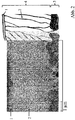
- Example 1 ( Fig. 2 ) an approximately 4 micron thick electrolyte was produced, wherein the first 3.5 microns were deposited with the supply of oxygen and an approximately 0.5 micron thick cover layer was applied without the supply of oxygen as a reactive gas.
- the electrolyte thus comprises a 3.5 ⁇ m layer with a higher oxygen content and a 0.5 ⁇ m thick cover layer with a lower oxygen content.
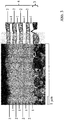
- Example 2 ( Fig. 3 ) has an electrolyte layer composite with a total of 8 intermediate layers, wherein alternately, starting with a metallically applied layer, each having an approximately 0.5 micron thick intermediate layer without Reactive gas and an approximately 0.5 micron thick intermediate layer were applied with the supply of reactive gas.
- a 20 to 60 microns thick porous cathode of lanthanum-strontium-cobalt-iron oxide (LSCF, (La 0.6 Sr 0.4 Co 0.8 Fe 0.2 ) O 3- ⁇ ) is printed by screen printing method, where before the screen printing, if necessary, the sample again a plasma treatment can be subjected. Activation of the cathode occurs in situ during the first hours of operation of the cell. In the in the Fig. 1-3 Examples shown missing in each case a CGO protective layer or the cathode.
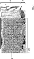
- the multilayer structure of the electrolyte can be seen.
- the columnar structure of the electrolyte which is known from the prior art example in Fig. 1 can extend over the entire thickness of the electrolyte is interrupted and limited to the thickness of an intermediate layer.
- the crystallites of the metallic and oxide-ceramic deposited layer differ in shape and in the formed crystal system. While the individual stems of the oxide-ceramic deposited layer form a tetragonal or cubic crystal system typical for 8YSZ and are preferably arranged in the growth direction in columnar form, the crystallites of the metallized layer are smaller and, due to the lack of oxygen atoms, usually crystallize out in other crystal systems.
- a tetragonal or cubic crystal system sets in by the incorporation of oxygen in the metallic layer.
- a gas-tight electrolyte with a thickness of 4 ⁇ m could be produced.
- the electrolyte in Example 1 ( Fig. 2 ) has a leak rate of 7.6 10 -4 hPa dm 3 s -1 cm -2
- the electrolyte has no other elements than yttrium, zirconium and oxygen.
Description
Die Erfindung betrifft eine Kathode-Elektrolyt-Anodeneinheit für eine elektrochemische Funktionseinrichtung, insbesondere für eine Hochtemperaturbrennstoffzelle, und ein Herstellungsverfahren dazu.The invention relates to a cathode-electrolyte anode unit for an electrochemical functional device, in particular for a high-temperature fuel cell, and a manufacturing method thereof.
Hochtemperaturbrennstoffzellen (Solid Oxide Fuel Cell - SOFC) ermöglichen eine direkte Umwandlung von chemischer Energie in elektrische Energie. Die elektrochemisch aktive Zelle einer SOFC besteht aus einer sogenannten Kathoden-Elektrolyt-Anoden-Einheit (Einzelzelle), bei der ein gasdichter Feststoffelektrolyt zwischen einer gasdurchlässigen Anode und einer gasdurchlässigen Kathode angeordnet ist. Der Feststoffelektrolyt besteht dabei meist aus einem festen keramischen Werkstoff aus Metalloxid, der Sauerstoffionen leitet, Elektronen aber nicht.Solid oxide fuel cells (SOFCs) allow direct conversion of chemical energy into electrical energy. The electrochemically active cell of an SOFC consists of a so-called cathode-electrolyte-anode unit (single cell), in which a gas-tight solid electrolyte between a gas-permeable anode and a gas-permeable cathode is arranged. The solid electrolyte usually consists of a solid ceramic material of metal oxide, which conducts oxygen ions, but not electrons.
Im Betrieb einer SOFC wird der Anode Brennstoff (beispielsweise Wasserstoff oder herkömmliche Kohlenwasserstoffe, wie Methan, Erdgas, Biogas, ...) zugeführt und dort katalytisch unter Abgabe von Elektronen oxidiert. Die Elektronen werden aus der Brennstoffzelle abgeleitet und fließen über einen elektrischen Verbraucher zur Kathode. An der Kathode wird ein Oxidationsmittel (beispielsweise Sauerstoff oder Luft) durch Aufnahme der Elektronen reduziert. Der elektrische Kreislauf schließt sich, indem die Sauerstoffionen über den Elektrolyten zur Anode fließen und an den entsprechenden Grenzflächen mit dem Brennstoff reagieren.During operation of an SOFC, the anode is supplied with fuel (for example hydrogen or conventional hydrocarbons, such as methane, natural gas, biogas, etc.) and is catalytically oxidized there with the emission of electrons. The electrons are derived from the fuel cell and flow via an electrical load to the cathode. At the cathode, an oxidant (eg, oxygen or air) is reduced by receiving the electrons. The electrical circuit closes as the oxygen ions flow across the electrolyte to the anode and react with the fuel at the appropriate interfaces.
Bei SOFC Systemen sind aus dem Stand der Technik verschiedene Ausführungsformen bekannt, die im Folgenden kurz skizziert werden sollen. Bei einer ersten Variante, technisch am weitesten fortgeschritten, ist der Elektrolyt die mechanisch tragende Zellkomponente ("Electrolyte Supported Cell", ESC). Die Schichtdicke des Elektrolyten ist hierbei verhältnismäßig groß, ca. 100-150 µm und besteht meist aus Yttriumoxid (YSZ) oder Scandiumoxid (ScSZ) stabilisierten Zirkoniumdioxid. Um eine ausreichende lonenleitfähigkeit des Elektrolyten zu erzielen müssen diese Brennstoffzellen bei einer verhältnismäßig hohen Betriebstemperatur von ca. 850-1000°C betrieben werden. Diese hohe Betriebstemperatur führt zu hohen Anforderungen an die verwendeten Materialien.In SOFC systems, various embodiments are known from the prior art, which are briefly outlined below. In a first variant, technically most advanced, the electrolyte is the mechanically-bearing cell component ("Electrolyte Supported Cell", ESC). The layer thickness of the electrolyte here is relatively large, about 100-150 microns and usually consists of yttria (YSZ) or scandium (ScSZ) stabilized zirconia. In order to achieve a sufficient ion conductivity of the electrolyte, these fuel cells must be operated at a relatively high operating temperature of about 850-1000 ° C. This high operating temperature leads to high demands on the materials used.
Die Bestrebungen nach niedrigerer Betriebstemperatur führten in Folge zur Entwicklung von unterschiedlichen Dünnschichtsystemen. Dazu zählen Anoden- bzw. Kathoden gestützte ("Anode-Supported Cell" bzw. "Cathode-Supported Cell") SOFC Systeme, bei denen ein relativ dickes (mind. ca 200 µm) mechanisch tragendes keramisches Anoden- bzw. Kathodensubstrat mit einer dünnen, elektrochemisch aktiven Anoden- bzw. Kathodenfunktionsschicht verbunden ist. Da die Elektrolytschicht keine mechanisch tragende Rolle mehr auszuführen hat, kann diese verhältnismäßig dünn ausgeführt werden und die Betriebstemperatur aufgrund des geringeren ohmschen Widerstands dementsprechend reduziert werden.Efforts to lower operating temperature resulted in the development of different thin film systems. These include anode- and cathode-supported ("anode-supported cell" or "cathode-supported cell") SOFC systems in which a relatively thick (at least about 200 microns) mechanically supporting ceramic anode or cathode substrate with a thin Electrochemically active anode or cathode functional layer is connected. Since the electrolyte layer no longer has to perform a mechanically supporting role, it can be made relatively thin and the operating temperature can be correspondingly reduced due to the lower ohmic resistance.
Neben diesen rein keramischen Systemen wurden als jüngste Generation SOFC Dünnschichtsysteme entwickelt, die auf einem metallischen Trägersubstrat basieren, sogenannte Metallgestützte SOFC ("Metall-Supported Cell", MSC). Diese metallisch-keramischen Verbundsysteme zeigen gegenüber rein keramischen Dünnschichtsystemen Vorteile hinsichtlich der Herstellungskosten, thermischen- und Redox-Zyklierbarkeit sowie der mechanischen Stabilität und können auf Grund ihres Dünnschichtelektrolyten zudem bei einer noch niedrigeren Betriebstemperatur von ca. 600°C bis 800 °C betrieben werden. Aufgrund ihrer spezifischen Vorteile sind sie insbesondere für mobile Anwendungen, wie beispielsweise zur elektrischen Versorgung von Personenkraftwagen oder Nutzfahrzeugen (APU-Auxiliary Power Unit) geeignet. Eine aus dem Stand der Technik bekannte, exemplarische MSC besteht aus einem ca. 1 mm dicken porösen, dadurch gasdurchlässigen, metallischen Trägersubstrat, auf das eine 60-70 µm dicke Kathoden-Elektrolyt-Anodeneinheit, der eigentlich elektrochemisch aktiven Schichtanordnung, angeordnet ist. Typischerweise ist die Anode dem Trägersubstrat zugewandt und in der Abfolge der Schichtanordnung näher am Metallsubstrat als die Kathode.In addition to these purely ceramic systems, SOFC thin film systems based on a metallic carrier substrate, so-called metal-supported SOFC ("metal-supported cell", MSC), have been developed as the latest generation. These metallic-ceramic composite systems show advantages over purely ceramic thin-film systems in terms of manufacturing costs, thermal and redox cyclability and mechanical stability and can also be operated at an even lower operating temperature of about 600 ° C to 800 ° C due to their thin-film electrolyte. Due to their specific advantages, they are particularly suitable for mobile applications, such as for the electrical supply of passenger cars or utility vehicles (APU-Auxiliary Power Unit). An exemplary MSC known from the state of the art consists of a porous carrier substrate which is about 1 mm thick, and thus permeable to gas, onto which a 60-70 μm thick cathode-electrolyte anode unit, which is actually electrochemically active layer arrangement, is arranged. Typically, the anode faces the carrier substrate and, in the sequence of the layer assembly, is closer to the metal substrate than the cathode.
Intensive Forschungsaktivitäten zur Leistungssteigerung von SOFC Systemen, insbesondere bei Anoden-, Kathoden- oder Metallsubstratgestützen SOFC, haben eine Verringerung der Schichtdicke des Elektrolyten zum Ziel, wobei gleichzeitig eine ausreichende Gasdichtheit gewährleistet bleiben muss (Leckrate < 1,0 x 10⁻³ hPa dm3 /(s cm2) (gemessen unter Luft mit Druckanstiegsmethode (Fa. Dr. Wiesner, Remscheid, Typ: Integra DDV) bei einer Druckdifferenz dp = 100 hPa).Intensive research activities to improve the performance of SOFC systems, especially for anode, cathode or metal substrate supports SOFC, have a reduction in the thickness of the electrolyte to the target, while ensuring sufficient gas tightness must be ensured (leak rate <1.0 x 10 -3 hPa dm 3 / (s cm 2 ) (measured in air with Pressure increase method (Dr. Wiesner, Remscheid, type: Integra DDV) at a pressure difference dp = 100 hPa).
Bekannte Herstellungsverfahren für keramische Dünnschichtelektrolyte umfassen neben nasskeramischen Verfahren wie Nasspulverbeschichten oder Siebdruck, bei denen der Elektrolyt zur erforderlichen Gasdichtheit im Anschluss (bei Verwendung von Yttrium stabilisierten Zirkoniumoxid (YSZ) bei etwa 1400°C) gesintert wird, Beschichtungsverfahren wie beispielsweise physikalische Gasphasenabscheidung (PVD - Physical Vapour Deposition).Known ceramic thin-film electrolyte fabrication methods include, in addition to wet-ceramic processes such as wet powder coating or screen printing, which sinter the electrolyte for required gas tightness (using yttria-stabilized zirconia (YSZ) at about 1400 ° C.), coating methods such as physical vapor deposition (PVD). Physical Vapor Deposition).
Beschichtungsverfahren wie PVD weisen aufgrund der geringeren Prozesstemperatur insbesondere für metallsubstratgestützte SOFC erhebliche Vorteile auf. Während Beschichtungsverfahren in der Regel verwendet werden, um die Eigenschaften von überwiegend glatten Oberflächen zu modifizieren, so steht man bei der Anwendung von PVD für SOFC vor der Herausforderung, auf einem porösen Substrat wie beispielsweise der Anode eine gasdichte Schicht mit möglichst geringer Dicke abzuscheiden. Das Schichtwachstum und die Mikrostruktur (entscheidend für die Gaspermeabilität) der aufgetragenen Elektrolytschicht wird wesentlich durch die Oberflächenstruktur des Substrats (Porosität, Oberflächenrauhigkeit, Risse, Defekte, ...) beeinflusst.Coating methods such as PVD have considerable advantages due to the lower process temperature, in particular for metal substrate-supported SOFCs. While coating methods are typically used to modify the properties of predominantly smooth surfaces, the challenge of using PVD for SOFC is to deposit a gas-tight layer as thin as possible on a porous substrate such as the anode. The layer growth and the microstructure (crucial for the gas permeability) of the applied electrolyte layer is significantly influenced by the surface structure of the substrate (porosity, surface roughness, cracks, defects, ...).
Bei Elektrodengestützten SOFC ist es in der Vergangenheit gelungen, mittels PVD, gasdichte Elektrolyte mit einer Schichtdicke von unter 3 µm, zu realisieren (
Zur Optimierung ist eine Ausführung des Elektrolyten aus einem Mehrlagenschichtverbund aus Gadolinium dotiertem Ceroxid (CGO), YSZ und CGO bekannt (
Beim Versuch, dieses bei anodengestützten SOFC verwendete Herstellungsverfahren auf metallsubstratgestützte SOFC (MSC) zu übertragen, stößt man auf folgende prozessbedingte Schwierigkeit. Aufgrund des metallischen Trägersubstrats müssen die Prozessschritte für MSC in reduzierender Atmosphäre erfolgen, die Sinterung der Anode findet unter geringem Sauerstoffpartialdruck statt. Unter diesen Bedingungen liegt in der Anode das Ni bereits überwiegend metallisch vor und ist vergröbert, es können Korngrößen bis zu ca. 1 µm auftreten. Die zu beschichtende, reduziert vorliegende Anode einer MSC weist daher eine deutlich höhere Oberflächenrauhigkeit und größere Poren auf als die oxidierte Anode bei Elektrodengestützten SOFC. Aus diesem Grund kann derzeit bei mit PVD hergestellten MSC Elektrolyten eine ausreichende Gasundurchlässigkeit nur bei einer Elektrolytschichtdicke ab etwa 5 µm erreicht werden (
Zur Verringerung der Gaspermeabilität von mittels Beschichtungsverfahren hergestellten Elektrolyten sind aus dem Stand der Technik weiters Hybridverfahren bekannt, bei denen dem Beschichtungsprozess ein thermischer Behandlungsschritt nachfolgt.To reduce the gas permeability of electrolytes produced by coating processes are further from the prior art Hybrid processes are known in which the coating process is followed by a thermal treatment step.
Ein derartiges Beispiel findet sich in
Ein weiterer Ansatz zur Herstellung einer gasundurchlässigen, äußerst dünnen Elektrolytschicht, bei dem ein Beschichtungsverfahren mit einem nachfolgenden Wärmebehandlungsschritt kombiniert wird, wird in
Weiters sind aus der Patentliteratur verschiedene Mehrlagenschichtsysteme für Elektrolyten bekannt, beispielsweise
Die Anforderungen an den Elektrolyten einer elektrochemischen Funktionseinrichtung wie einer SOFC lassen sich wie folgt zusammenfassen: bei Betriebstemperatur hohe Sauerstoffionenleitfähigkeit und geringe Elektronenleitfähigkeit, chemische und mechanische Stabilität bei verwendeter Prozessgasatmosphäre (Luft bzw. Brenngas-Atmosphäre), gute Hafteigenschaften mit angrenzenden Funktionsschichten und ausreichende Gasdichtheit, um das Prozessgas an der Anodenseite (Brenngas) vom Prozessgas an der Kathodenseite (Luft) zu trennen.The requirements for the electrolyte of an electrochemical functional device such as an SOFC can be summarized as follows: high oxygen ion conductivity and low electron conductivity at operating temperature, chemical and mechanical stability in the process gas atmosphere used (air or fuel gas atmosphere), good adhesive properties with adjacent functional layers and sufficient gas tightness, to separate the process gas at the anode side (fuel gas) from the process gas at the cathode side (air).
Der vorliegenden Erfindung liegt die Aufgabe zugrunde, eine kostengünstige Kathode-Elektrolyt-Anodeneinheit für den Einsatz in einer elektrochemischen Funktionseinrichtung, insbesondere in einer Hochtemperatur-Brennstoffzelle, zu schaffen, bei dem der Elektrolyt voranstehend genannten Anforderungen genügt und eine möglichst geringen ohmschen Widerstand aufweist. Das Verfahren zur Herstellung einer solchen Kathode-Elektrolyt-Anodeneinheit soll insbesondere für eine MSC geeignet sein.The present invention has for its object to provide a low-cost cathode-electrolyte anode unit for use in an electrochemical functional device, in particular in a high-temperature fuel cell, in which the electrolyte meets the above-mentioned requirements and has the lowest possible ohmic resistance. The method for producing such a cathode-electrolyte anode unit should be particularly suitable for an MSC.
Diese Aufgabe wird durch die Gegenstände und Verfahren mit den Merkmalen gemäß den unabhängigen Patentansprüchen gelöst.This object is solved by the objects and methods having the features according to the independent patent claims.
Erfindungsgemäß wird eine Kathode-Elektrolyt-Anodeneinheit vorgeschlagen, bei der der zwischen Kathode und Anode angeordnete Festkörperelektrolyt mehrlagig ausgeführt ist und mittels physikalischer Gasphasenabscheidung hergestellt wird. Unter physikalischer Gasphasenabscheidung werden insbesondere Sputtern (Kathodenzerstäubung), Reaktivsputtern (reaktive Kathodenzerstäubung), Gasphasenabscheidung mit Hilfe eines Elektronenstrahls (Electron-beam Physical Vapor Deposition), Laserstrahlverdampfen (Pulsed Laser Deposition) oder vergleichbare Beschichtungsverfahren oder eine Kombination dieser Beschichtungsverfahren gezählt. Der Festkörperelektrolyt weist einen schichtförmigen Aufbau aus mindestens einer ersten Schicht und mindestens einer zweiten Schicht auf, wobei die zweite Schicht einen höheren Sauerstoffgehalt aufweist als die erste Schicht und die beiden Schichten mit Ausnahme von Sauerstoff im Wesentlichen bis auf Spurenelemente die gleiche Zusammensetzung aufweisen. Die beiden Schichten unterscheiden sich daher primär in ihrem Sauerstoffgehalt.According to the invention, a cathode-electrolyte anode unit is proposed in which the solid-state electrolyte arranged between the cathode and the anode is designed in multiple layers and is produced by means of physical vapor deposition. Physical vapor deposition includes, in particular, sputtering (cathode sputtering), reactive sputtering (reactive sputtering), electron beam (Vapor Deposition) vapor deposition, pulsed laser deposition, or comparable coating processes or a combination of these coating processes. The solid electrolyte has a layered structure at least one first layer and at least one second layer, wherein the second layer has a higher oxygen content than the first Layer and the two layers with the exception of oxygen substantially to trace elements have the same composition. The two layers therefore differ primarily in their oxygen content.
Die erste Schicht mit niedrigerem Sauerstoffgehalt kann metallisch aufgebracht sein, die zweite Schicht mit höherem Sauerstoffgehalt kann oxidkeramisch aufgebracht sein. Unter metallisch aufgebracht ist das Abscheiden einer zuvor (bspw. mittels eines Sputterverfahrens) in die Gasphase überführten metallischen Verbindung zu verstehen, unter oxidkeramisch aufgebracht das Abscheiden eines Oxids dieser metallischen Verbindung. Das Metalloxid kann dabei beispielsweise unter Verwendung eines (Sputter)Targets bestehend aus dem Metalloxid abgeschieden werden oder unter Verwendung eines metallischen Targets unter Zufuhr von Sauerstoff als Reaktivgas (Reaktives Sputtern). Prozessbedingt, beispielsweise aufgrund von Restsauerstoff in der Beschichtungsanlage, kann sich in die metallisch aufgebrachte Schicht etwas Sauerstoff einlagern, die metallisch aufgebrachte Schicht muss daher nicht rein metallisch sein und kann nicht-metallische Phasen aufweisen. Die metallisch aufgebrachte Schicht weist aber einen deutlich niedrigeren Sauerstoffgehalt auf als die oxidkeramisch aufgebrachte Schicht. Die erste Schicht ist also unterstöchiometrisch ausgebildet. Unter "unterstöchiometrisch" ist zu verstehen, dass beim Abscheiden der entsprechenden Schicht die Sauerstoffeinlagerung geringer ist als sie zur Erzielung eines stöchiometrischen Verhältnisses in der abgeschiedenen Schicht notwendig ist.The first layer with lower oxygen content may be applied metallically, the second layer with higher oxygen content may be applied oxide ceramic. The term metallic applied means the deposition of a metallic compound which has previously been converted into the gas phase (for example by means of a sputtering process), deposited under oxide-ceramic deposition of an oxide of this metallic compound. The metal oxide can be deposited, for example, using a (sputtering) target consisting of the metal oxide or by using a metallic target with the supply of oxygen as a reactive gas (reactive sputtering). Due to the process, for example, due to residual oxygen in the coating system, some oxygen can accumulate in the layer applied to metal, the metal-deposited layer must therefore not be purely metallic and may have non-metallic phases. However, the metallically applied layer has a significantly lower oxygen content than the oxide-ceramic layer applied. The first layer is thus formed substoichiometric. By "substoichiometric" is meant that, upon deposition of the corresponding layer, oxygen incorporation is less than necessary to achieve a stoichiometric ratio in the deposited layer.
Der erfindungsgemäßen Lösung liegt der Gedanke zugrunde, dass eine metallisch aufgebrachte Schicht in vorteilhafter Weise aufgrund der geringeren Schmelztemperatur des Metalls im Vergleich zum entsprechenden Metalloxid unter sonst gleichen Prozessbedingungen deutlich kompakter und dichter abgeschieden werden kann als eine oxidkeramische Schicht aus dem zugehörigen Metalloxid. Die Stängel in der metallisch abgeschiedenen Schicht sind in der Regel kleiner als die Stängel in der entsprechenden oxidkeramisch abgeschiedenen Schicht. Durch den Wechsel zwischen Schichten mit niedrigerem oder höheren Sauerstoffgehalt (metallisch und oxidkeramisch aufgebrachten Schichten) wird zudem die für Beschichtungsverfahren charakteristische Stängelstruktur des Elektrolyten, wobei sich bei einem herkömmlichen, mittels PVD hergestellten Elektrolyten aus 8YSZ einzelne Stängel typischerweise über die gesamte Dicke des Elektrolyten erstrecken können, unterbrochen und die längliche Ausdehnung der Kristallite in Wachstumsrichtung auf die Dicke einer Zwischenschicht beschränkt. Da der Elektrolyt keinem anschließenden Sinterverfahren unterzogen wird, bleiben die Form und die bevorzugte Ausrichtung der Kristallite in Wachstumsrichtung bestehen. In der Regel wirkt sich diese positiv auf die Sauerstoffionenleitfähigkeit des Elektrolyten aus. Die metallisch aufgebrachte unterstöchiometrische Schicht ist ursprünglich nicht bzw. äußerst gering Sauerstoffionen leitend, die Sauerstoffionen - Leitfähigkeit des Elektrolyten erhöht sich aber signifikant, wenn der Elektrolyt in Luft bzw. sauerstoffhältiger Atmosphäre, beispielsweise während der ersten Minuten beim ersten Betrieb der Kathode-Elektrolyt-Anodeneinheit, ausgelagert wird und sich Sauerstoffionen in die metallisch abgeschiedene(n) Schicht(en) einlagern. Die chemische Zusammensetzung der einzelnen Schichten des Elektrolyten ist dann im Wesentlichen gleich, es können aber strukturelle Unterschiede, beispielsweise im Kristallsystem, in dem die Kristallite der ursprünglich metallisch aufgebrachten unterstöchiometrischen bzw. oxidkeramisch aufgebrachten Schichten möglicherweise unterschiedlich auskristallisiert sind, weiterhin bestehen bleiben. Durch die Sauerstoffeinlagerung findet eine Volumenzunahme der metallisch aufgebrachten Schicht mit ursprünglich niedrigem Sauerstoffgehalt statt, wodurch sich die metallisch aufgebrachte Schicht zusätzlich verdichtet und etwaige Zwischenräume verkleinert werden können. Aufgrund der bis auf Spurenelemente vergleichbaren Zusammensetzung sind die angrenzenden Schichten des Elektrolyten einander gegenüber chemisch beständig und weisen einen vergleichbaren thermischen Ausdehnungskoeffizienten auf.The inventive solution is based on the idea that a metallically deposited layer can be deposited significantly more compact and dense in an advantageous manner due to the lower melting temperature of the metal compared to the corresponding metal oxide under otherwise identical process conditions as an oxide ceramic layer of the associated metal oxide. The stems in the metallically deposited layer are typically smaller than the stems in the corresponding oxide-ceramic deposited layer. By changing between layers with lower or higher oxygen content (metallic and oxide ceramic applied layers) is also the characteristic of coating process stem structure of the electrolyte, wherein at a conventional PVD-made electrolytes from 8YSZ may extend single stems typically across the entire thickness of the electrolyte, interrupted and the elongated expansion of the crystallites in the growth direction limited to the thickness of an intermediate layer. Since the electrolyte is not subjected to a subsequent sintering process, the shape and the preferred orientation of the crystallites in the growth direction remain. As a rule, this has a positive effect on the oxygen ion conductivity of the electrolyte. The metallically deposited substoichiometric layer is not initially or extremely low oxygen ion conductive, but the oxygen ion conductivity of the electrolyte increases significantly when the electrolyte in air or oxygen-containing atmosphere, for example, during the first minutes in the first operation of the cathode-electrolyte-anode unit , Is paged and store oxygen ions in the metal deposited layer (s). The chemical composition of the individual layers of the electrolyte is then essentially the same, but structural differences, for example in the crystal system, in which the crystallites of the initially metallically deposited substoichiometric or oxide-ceramic layers are possibly crystallized differently, may continue to exist. Due to the oxygen storage, an increase in volume of the metallically applied layer with originally low oxygen content takes place, as a result of which the metallically applied layer is additionally compacted and any intermediate spaces can be reduced. Due to the comparable composition to trace elements, the adjacent layers of the electrolyte are chemically resistant to each other and have a comparable coefficient of thermal expansion.
In einer ersten Grundausführungsform weist der Elektrolyt zwei Schichten auf, eine erste Schicht mit niedrigerem Sauerstoffgehalt, die bevorzugt metallisch aufgebracht wird, und eine zweite Schicht mit höherem Sauerstoffgehalt, welche bevorzugt oxidkeramisch aufgebracht wird, wobei sich bis auf den Sauerstoffgehalt und etwaigen Verunreinigungen oder Spurenelementen die chemische Zusammensetzung der beiden Schichten nicht unterscheidet. Insbesondere bei Selten-Erd- oder Erdalkali-Elemente-haltigen Elektrodenmaterial kann zwischen Elektrolyt und Elektrode mindestens eine weitere Funktionsschicht wie beispielsweise eine Diffusionsbarriereschicht aus CGO vorgesehen sein. Typischerweise wird die metallische Schicht mit niedrigerem Sauerstoffgehalt als Deckschicht auf die oxidkeramische Schicht mit höherem Sauerstoffgehalt aufgebracht.In a first basic embodiment, the electrolyte has two layers, a first layer having a lower oxygen content, which is preferably applied metallically, and a second layer having a higher oxygen content, which is preferably applied by oxide ceramics, with the exception of the oxygen content and any impurities or trace elements chemical composition of the two layers does not differ. Especially with rare earth or alkaline earth elements-containing Electrode material may be provided between electrolyte and electrode at least one further functional layer such as a diffusion barrier layer of CGO. Typically, the lower oxygen content metal layer is applied as a topcoat to the higher oxygen content oxide ceramic layer.
In einer bevorzugten Ausführungsform wird der Wechsel zwischen den Schichten mit unterschiedlichem Sauerstoffgehalt (oxidkeramisch und metallisch aufgebracht) mehrmals wiederholt, der Elektrolyt besteht dann aus einem Schichtsystem aus mindestens drei Zwischenschichten, wobei erste, metallisch aufgebrachte Schichten mit niedrigerem Sauerstoffgehalt und zweite, oxidkeramisch aufgebrachte Schichten mit höherem Sauerstoffgehalt in alternierender Weise übereinander angeordnet sind. Bevorzugt ist die Zusammensetzung der einzelnen oxidkeramisch bzw. metallisch aufgebrachten Schicht(en) gleich.In a preferred embodiment, the change between the layers with different oxygen content (oxide ceramic and metallic applied) is repeated several times, the electrolyte then consists of a layer system of at least three intermediate layers, wherein first, metallically deposited layers with lower oxygen content and second, oxide ceramic applied layers higher oxygen content in an alternating manner are arranged one above the other. The composition of the individual oxide-ceramic or metallically applied layer (s) is preferably the same.
Bei einem dreilagigen Elektrolytschichtsystem ergibt sich als Abfolge der Schichtanordnung daher Zwischenschicht mit höherem Sauerstoffgehalt, Zwischenschicht mit niedrigerem Sauerstoffgehalt, Zwischenschicht mit höherem Sauerstoffgehalt (bzw. oxidkeramisch/metallisch/oxidkeramisch aufgebracht) bzw. Zwischenschicht mit niedrigerem Sauerstoffgehalt, Zwischenschicht mit höherem Sauerstoffgehalt, Zwischenschicht mit niedrigerem Sauerstoffgehalt (bzw. metallisch/oxidkeramisch/metallisch aufgebracht). Die Vorteile der Erfindung kommen insbesondere bei mehrmaligem Wechsel zwischen Schichten mit unterschiedlichem Sauerstoffgehalt zur Geltung, in vorteilhaften Ausführungsvarianten kann der mehrlagige Elektrolyt beginnend von insgesamt 4 Zwischenschichten (d.h. in alternierender Anordnung insgesamt 2 oxidkeramisch aufgebrachte Schichten mit höherem Sauerstoffgehalt und 2 metallisch aufgebrachte Schichten mit niedrigerem Sauerstoffgehalt) bis hin zu insgesamt 50 Zwischenschichten (d.h. in alternierender Anordnung insgesamt 25 oxidkeramisch aufgebrachte Schichten mit höherem Sauerstoffgehalt und 25 metallisch aufgebrachte Schichten mit niedrigerem Sauerstoffgehalt) aufweisen. Bei gleichbleibender Gesamtdicke des Elektrolyten ist eine höhere Anzahl von dünnen, alternierend aufgebrachten Zwischenschichten vorteilhaft für die Gasdichtheit des Elektrolyten, da die stängelige, kolumnare Struktur der Kristalliten, an dessen Korngrenzen sich längliche, sich über die gesamte Dicke der Zwischenschicht erstreckende Zwischenräume ausbilden können, häufiger unterbrochen wird. Zudem können durch das mehrmalige Wiederholen der Schichten mit unterschiedlichem Sauerstoffgehalt potentielle Schichtfehler des Substrats, auf dem der Elektrolyt aufgetragen wird, besser ausheilen. Zu beachten ist aber, dass eine sehr hohe Anzahl von Zwischenschichten sich aufgrund der großen Grenzfläche zwischen den Zwischenschichten eventuell negativ auf die Sauerstoffionentransportfähigkeit des Elektrolyten auswirken kann.In the case of a three-layer electrolyte layer system, the sequence of the layer arrangement therefore results in a higher oxygen content intermediate layer, lower oxygen content intermediate layer, higher oxygen content (or oxide ceramic / metallic / oxide ceramic applied) or lower oxygen intermediate layer, higher oxygen content intermediate layer, lower intermediate layer Oxygen content (or metallic / oxide ceramic / metallic applied). The advantages of the invention are particularly noticeable when switching between layers with different oxygen content, in advantageous embodiments, the multilayered electrolyte starting from a total of 4 intermediate layers (ie, in an alternating arrangement, a total of 2 oxide ceramic deposited layers with higher oxygen content and 2 metallically deposited layers with lower oxygen content ) to a total of 50 intermediate layers (ie, in total arrangement, a total of 25 oxide-ceramic layers with higher oxygen content and 25 metallic layers with lower oxygen content). With a constant total thickness of the electrolyte, a higher number of thin, alternately applied intermediate layers is advantageous for the gas-tightness of the electrolyte, since the columnar, columnar structure of the crystallites, at whose Grain boundaries can form elongated, extending over the entire thickness of the intermediate layer spaces is interrupted more frequently. In addition, by repeating the layers with different oxygen content several times, potential layer defects of the substrate on which the electrolyte is applied can better heal. It should be noted, however, that a very high number of intermediate layers may have a negative effect on the oxygen-ion transportability of the electrolyte due to the large interface between the intermediate layers.
Auch wenn sich mittels Gasphasenabscheidungsverfahren regelmäßig Schichtdicken unter 200 nm realisieren lassen, so zeigt sich, dass eine Mindestdicke einer Zwischenschicht (metallisch oder oxidkeramisch aufgebracht) von etwa 200 nm vorteilhaft ist. Die Schichtdicke der metallisch aufgebrachten Zwischenschicht mit niedrigerem Sauerstoffgehalt soll 800 nm, insbesondere 500 nm nicht überschreiten, da aufgrund der späteren Sauerstoffeinlagerung eine Volumenzunahme stattfindet und dadurch Gefahr für ein Abplatzen bzw. Abblättern der Zwischenschicht besteht. Bei gleichbleibender Leckrate kann daher durch Verwendung des erfindungsgemäßen mehrlagigen Elektrolyten die Schichtdicke verringert und somit der ohmsche Widerstand reduziert werden.Even if layer thicknesses of less than 200 nm can be regularly achieved by means of vapor deposition methods, it is evident that a minimum thickness of an intermediate layer (applied with metallic or oxide ceramic) of about 200 nm is advantageous. The layer thickness of the metallically deposited intermediate layer with a lower oxygen content should not exceed 800 nm, in particular 500 nm, since an increase in volume takes place due to the later oxygen deposition and thus there is a danger of the intermediate layer spalling or flaking off. If the leak rate remains the same, the layer thickness can therefore be reduced by using the multilayered electrolyte according to the invention, and thus the ohmic resistance can be reduced.
Ein für die Herstellung des mehrlagigen Elektrolyten besonders geeigneter Werkstoff ist mit Erdalkali-Elementen oder Seltenen Erden dotiertes Zirkonium LnyZr1-y, wobei Ln = Y, Sc, Yb, Er und 0.08≤y≤0.12, für die metallisch abgeschiedenen Zwischenschichten und ein entsprechendes Oxid im stöchiometrischen Verhältnis LnyZr1-yO2-δ wobei Ln= Y, Sc, Yb, Er und 0.08≤y≤0.12 für die oxidkeramisch aufgetragene Zwischenschicht. Ebenso geeignet ist dotiertes Cer AxCe1-x, wobei A=Gd, Sm, Y, Ca und 0.05≤x≤0.3 für die metallisch aufgetragene Zwischenschicht und entsprechend dotiertes Ceroxid AxCe1-xO2-δ, wobei A=Gd, Sm, Y, Ca und 0.05≤x≤0.3 für die oxidkeramisch aufgetragene Schicht. In die metallisch abgeschiedenen Zwischenschichten kann etwas Sauerstoff eingelagert sein, der Sauerstoffgehalt ist aber unterstöchiometrisch und deutlich geringer als in der oxidkeramisch aufgetragenen Zwischenschicht.An especially suitable material for the preparation of the multilayer electrolyte is zirconium doped with alkaline earth elements or rare earths Ln y Zr 1-y , where Ln = Y, Sc, Yb, Er and 0.08≤y≤0.12, for the metallic deposited intermediate layers and a corresponding oxide in the stoichiometric ratio Ln y Zr 1-y O 2 -δ wherein Ln = Y, Sc, Yb, Er and 0.08≤y≤0.12 for the oxide-ceramic applied intermediate layer. Also suitable is doped cerium A x Ce 1-x , where A = Gd, Sm, Y, Ca and 0.05≤x≤0.3 for the metallic deposited intermediate layer and correspondingly doped cerium oxide A x Ce 1-x O 2 -δ , where A = Gd, Sm, Y, Ca and 0.05≤x≤0.3 for the oxide-ceramic deposited layer. Some oxygen may be incorporated in the intermediate layers deposited in metal, but the oxygen content is substoichiometric and significantly lower than in the intermediate layer applied by means of oxide ceramic.
Ein wesentlicher Vorteil der Erfindung ist, dass zur Herstellung des mehrlagigen Elektrolyten ein teurer, energie- und zeitaufwendiger Sinterprozess bei hohen Temperaturen vermieden werden kann. Zur Fertigung des Elektrolyten kommt ein physikalisches Gasphasenabscheidungsverfahren als Beschichtungsverfahren zur Anwendung. Das Elektrolytmaterial wird dabei in die Gasphase übergeführt und zum zu beschichtenden Substrat geführt, wo es kondensiert. Es wird in alternierender Abfolge eine Schicht mit niedrigerem Sauerstoffgehalt und eine Schicht mit höherem Sauerstoffgehalt (metallische oder eine oxidkeramisch aufgebrachte Schicht) auf einem porösen Substrat wie der Elektrode oder gegebenenfalls einer weiteren Funktionsschicht, falls eine Funktionsschicht zwischen Elektrode und Elektrolyt vorgesehen ist, übereinander aufgebracht. Als Beschichtungsverfahren sind für die Erfindung insbesondere Sputterdepositionsverfahren wie DC-Sputtern, HF-Sputtern, lonenstrahlsputtern, Magnetronsputtern oder reaktives Sputtern zu nennen. Besonders vorteilhaft erweist sich sogenanntes Hohlkathoden-Gasfluss-Sputtern (Gas Flow Sputtering), ein spezielles Sputterdepositionsverfahren, bei dem festes Material durch Kathodenzerstäubung in einer Hohlkathoden-Glimmentladung abgetragen wird und mittels eines durch die Hohlkathode strömenden Arbeitsgases, meist Argon, zum außerhalb der Hohlkathode befindlichen Substrat transportiert wird, wo es als Schicht niederschlägt.
Oxidschichten können in einem reaktiven Prozess hergestellt werden. Dazu wird an der Hohlkathodenmündung, wo die Mischung des Arbeitsgases mit dem zerstäubten Kathodenmaterial aus der Hohlkathode ausströmt, Sauerstoff 17 als Reaktivgas zugeführt. Durch die Strömung des Arbeitsgases kann das Reaktivgas nicht zur Targetoberfläche vordringen, wodurch Plasma-Instabilitäten oder Ratenminderung, wie sie häufig bei reaktivem Magnetronsputtern auftritt, vermieden werden. Da kein Magnetfeld benötigt wird, erfolgt der Targetabtrag gleichmäßig und es kann mit sehr hoher Leistungsdichte gearbeitet werden, was einer hohen Beschichtungsrate zu Gute kommt. Ein besonderer Vorteil des Hohlkathoden-Gasfluss-Sputterns in Hinblick auf die vorliegende Erfindung ist, dass der Wechsel zwischen metallisch und oxidkeramisch aufgebrachten Schichten während des Beschichtungsvorganges einfach durch Einschalten bzw. Abschalten der Zufuhr von Sauerstoff als Reaktivgas bei sonst gleichbleibenden Parametern erfolgen kann und der mehrlagige Elektrolyt prozesstechnisch sukzessive und ohne Unterbrechung in einer Anlage hergestellt werden kann, ohne dass die Probe zwischen den Beschichtungen abgekühlt oder die Beschichtungskammer geöffnet werden müsste. Es lässt sich dadurch ein sehr guter Kontakt und Haftung zwischen den einzelnen Schichten erzielen. Aufgrund von Restsauerstoff in der Anlage kann sich auch in die metallisch aufgebrachte Schicht etwas Sauerstoff einlagern, die metallisch aufgebrachte Schicht muss daher nicht rein metallisch sein und kann nicht-metallische Phasen aufweisen. Sie weist aber einen deutlich niedrigeren Sauerstoffgehalt auf als die oxidkeramisch aufgebrachte Schicht. Zusätzlich kann am Substrat eine Bias-Spannung 18 zwischen Anode und Substrathalter 19 angelegt werden, um den Energieeintrag der Arbeitsgasionen auf das Substrat zu erhöhen und die abgeschiedene Schicht zu verdichten. Für die Schichtbildung kann es vorteilhaft sein, den Substrathalter zu heizen (keramischer Heizer 20). Um größere Flächen beschichten zu können, muss der Substrathalter 19 mit der zu beschichtenden Probe 21 vor der Quelle bewegt werden. Dies kann sowohl durch eine Pendelbewegung als auch durch ein langsames Vorbeifahren des Substrathalters vor der Quelle geschehen. Neben der Bias-Spannung spielt die Substrattemperatur, der Arbeitsgasfluss, der Reaktivgasfluss und der Abstand von Quellenfront zu Substratoberfläche eine Rolle für die Beschichtungsrate sowie der abgeschiedenen Schichtstruktur. Eine Vorrichtung für das Hohlkathoden-Gasfluss-Sputtern wird beispielsweise in
Die erfindungsgemäße Kathode-Elektrolyt-Anodeneinheit ist für Anoden- bzw. Kathodengestützte SOFC einsetzbar, im speziellen für MSC, wo die Kathode-Elektrolyt-Anodeneinheit auf ein metallisches Trägersubstrat aufgebracht und gestützt wird. Sie kann aber auch beispielsweise für einen Elektrolyseur oder in der Membrantechnologie zur elektrochemischen Gastrennung eingesetzt werden.The cathode-electrolyte anode unit of the present invention is applicable to anode- and cathode-assisted SOFCs, especially for MSC, where the cathode-electrolyte-anode unit is deposited and supported on a metallic carrier substrate. But it can also be used for example for an electrolyzer or in membrane technology for electrochemical gas separation.
Die Erfindung wird anhand nachfolgender Beispiele näher erläutert, wobei auf die
Im Beispiel 1 (
Das Beispiel 2 (
Auf diesem Elektrolyt wurde jeweils eine weitere 1 bis 2 µm dicke CGO Schutzschicht mit Hilfe eines PVD Verfahrens aufgebracht. Diese Schutzschicht verhindert eine chemische Reaktion zwischen Elektrolyt und Kathodenmaterial, insbesondere die Bildung von Strontiumzirkonaten (LaSrZrO, SrZrO).In this electrolyte, in each case a further 1 to 2 microns thick CGO protective layer was applied by means of a PVD process. This protective layer prevents a chemical reaction between electrolyte and cathode material, in particular the formation of strontium zirconates (LaSrZrO, SrZrO).
Abschließend wird eine 20 bis 60 µm dicke poröse Kathode aus Lanthan-Strontium-Kobalt-Eisenoxid (LSCF, (La0.6 Sr0.4 Co0.8 Fe0.2) O3-δ) mittels Siebdruckverfahren aufgedruckt, wobei vor dem Siebdruck gegebenenfalls die Probe nochmals einer Plasmabehandlung unterzogen werden kann. Die Aktivierung der Kathode erfolgt in situ während der ersten Betriebsstunden der Zelle. Bei den in den
In beiden Ausführungsbeispielen ist die mehrlagige Struktur des Elektrolyten ersichtlich. Die kolumnare Struktur des Elektrolyten, die sich aus dem aus dem Stand der Technik bekannten Beispiel in
Im späteren Betrieb stellt sich durch Einlagerung von Sauerstoff auch in der metallischen Schicht ein tetragonales oder kubisches Kristallsystem ein.In later operation, a tetragonal or cubic crystal system sets in by the incorporation of oxygen in the metallic layer.
Erfindungsgemäß konnte ein gasdichter Elektrolyt mit 4 µm Dicke hergestellt werden. Der Elektrolyt in Beispiel 1 (
Claims (15)
- Cathode-electrolyte-anode unit for an electrochemical functional device, more particularly a high-temperature fuel cell, comprising a multi-layered solid electrolyte (5), arranged between a porous anode (3) and a porous cathode (4), the solid electrolyte being produced by a physical vapour deposition process and comprising a layered structure of at least one first layer (1) and at least one second layer (2), the second layer (2) comprising a higher oxygen content than the first layer (1), and the first and second layers having substantially the same composition except for oxygen.
- Cathode-electrolyte-anode unit according to Claim 1, characterized in that the solid electrolyte comprises an alternating layer sequence wherein first layers with lower oxygen content (1) and second layers with higher oxygen content (2) are arranged alternately one above another.
- Cathode-electrolyte-anode unit according to Claim 2, characterized in that the solid electrolyte is composed of an alternating layer sequence of a total of at least two first layers with lower oxygen content (1) and at least two second layers with higher oxygen content (2).
- Cathode-electrolyte-anode unit according to any of the preceding claims, characterized in that the first layer or layers with lower oxygen content (1) and the second layer or layers with higher oxygen content (2) form a different crystal structure.
- Cathode-electrolyte-anode unit according to any of the preceding claims, characterized in that the first layer or layers with lower oxygen content (1) has or have in each case a layer thickness of between 200 and 800 nm, more particularly a layer thickness of between 300 and 500 nm.
- Cathode-electrolyte-anode unit according to any of the preceding claims, characterized in that the second layer or layers with higher oxygen content (2) has or have in each case a layer thickness of between 200 and 800 nm.
- Cathode-electrolyte-anode unit according to any of the preceding claims, characterized in that the layer thickness of the solid electrolyte is between 1 and 10 µm.
- Cathode-electrolyte-anode unit according to any of the preceding claims, characterized in that the first layer or layers (1) consist of Zr doped with alkaline earth elements or rare earths, more particularly of Y-doped Zr or of Sc-doped Zr, or of Gd-doped Ce and substoichiometrically intercalated oxygen, and the second layer or layers are formed from a corresponding stoichiometric oxide.
- Cathode-electrolyte-anode unit according to any of the preceding claims, characterized in that at least one further layer, more particularly a diffusion barrier layer, is arranged between the multi-layered solid electrolyte and the electrodes.
- Use of the cathode-electrolyte-anode unit according to any of the preceding claims in a metal-substrate-supported fuel cell, in an anode-supported fuel cell or in a cathode-supported fuel cell.
- Method for producing a multi-layered solid electrolyte with metallically (1) and oxide-ceramically (2) applied layers arranged in alternation for an electrochemical functional device, more particularly a high-temperature fuel cell, on the basis of a vapour deposition process, comprising the steps ofa. providing a (porous) substrateb. alternatively generating a metallically (1) or an oxide-ceramically (2) applied layer, wherethe metallically applied layer (1) is produced by depositing a mixture of metals converted beforehand (by means of a sputtering process) into the gas phase,and the oxide-ceramically applied layer (2) is produced by depositing the mixture of metals converted beforehand into the gas phase (or gaseous mixture), with supply of oxygen or of an oxygen-containing gas as reactive gas,c. singly or multiply repeating step b), in order to obtain a layer sequence in which metallically (1) and oxide-ceramically (2) applied layers are arranged in alternation one above another.
- Method according to Claim 11, characterized in that the substrate is coated by means of a gas flow sputtering process, more particularly a hollow-cathode gas flow sputtering process.
- Method according to Claim 11 or 12, characterized in that the layer thickness of the metallically applied layer or layers (1) is between 200 and 800 nm.
- Method according to any of Claims 11 to 13, characterized in that the layer thickness of the oxide-ceramically applied layer or layers (2) is between 200 and 800 nm.
- Method according to any of Claims 11 to 13, characterized in that as first layer an oxide-ceramically applied layer (2) with a layer thickness of between 500 nm and 3 µm is applied to the substrate, and possible subsequent oxide-ceramically applied layers (2) have a layer thickness of between 200 and 800 nm.
Applications Claiming Priority (2)
| Application Number | Priority Date | Filing Date | Title |
|---|---|---|---|
| DE102013008472.5A DE102013008472A1 (en) | 2013-05-21 | 2013-05-21 | Multi-layered layer arrangement for a solid electrolyte |
| PCT/EP2014/001352 WO2014187559A1 (en) | 2013-05-21 | 2014-05-20 | Multi-layer sandwich structure for a solid-state electrolyte |
Publications (2)
| Publication Number | Publication Date |
|---|---|
| EP3000149A1 EP3000149A1 (en) | 2016-03-30 |
| EP3000149B1 true EP3000149B1 (en) | 2017-05-10 |
Family
ID=50897525
Family Applications (1)
| Application Number | Title | Priority Date | Filing Date |
|---|---|---|---|
| EP14728826.0A Not-in-force EP3000149B1 (en) | 2013-05-21 | 2014-05-20 | Multi-layer sandwich structure for a solid-state electrolyte |
Country Status (10)
| Country | Link |
|---|---|
| US (1) | US10312540B2 (en) |
| EP (1) | EP3000149B1 (en) |
| JP (1) | JP6600300B2 (en) |
| KR (1) | KR20160010465A (en) |
| CN (1) | CN105493327B (en) |
| CA (1) | CA2911454A1 (en) |
| DE (1) | DE102013008472A1 (en) |
| DK (1) | DK3000149T3 (en) |
| TW (1) | TWI634696B (en) |
| WO (1) | WO2014187559A1 (en) |
Families Citing this family (4)
| Publication number | Priority date | Publication date | Assignee | Title |
|---|---|---|---|---|
| JP6014807B2 (en) * | 2014-11-20 | 2016-10-26 | 株式会社プラズマイオンアシスト | FUEL CELL SEPARATOR OR FUEL CELL COLLECTING MEMBER AND METHOD FOR PRODUCING THE SAME |
| CN105762391B (en) * | 2016-04-15 | 2019-01-08 | 暨南大学 | Component forms integrated proton conductor low-temperature solid oxide battery and its preparation |
| US10930844B2 (en) | 2018-10-11 | 2021-02-23 | International Business Machines Corporation | Three-terminal oxygen intercalation neuromorphic devices |
| KR20210076688A (en) | 2019-12-16 | 2021-06-24 | 삼성전자주식회사 | Composite solid electrolyte, electrochemical cell including the same, and method of preparing the composite solid electrolyte |
Family Cites Families (27)
| Publication number | Priority date | Publication date | Assignee | Title |
|---|---|---|---|---|
| US5171645A (en) * | 1991-01-08 | 1992-12-15 | Gas Research Institute, Inc. | Zirconia-bismuth oxide graded electrolyte |
| AU5634896A (en) * | 1996-05-01 | 1997-11-19 | Gas Research Institute, Inc. | Stable high conductivity functionally gradient compositionally layered solid state electrolytes and membranes |
| JP3843766B2 (en) | 2000-07-04 | 2006-11-08 | 日産自動車株式会社 | Solid oxide fuel cell |
| US6558831B1 (en) * | 2000-08-18 | 2003-05-06 | Hybrid Power Generation Systems, Llc | Integrated SOFC |
| JP4840718B2 (en) * | 2001-08-14 | 2011-12-21 | 日産自動車株式会社 | Solid oxide fuel cell |
| JP2003142123A (en) * | 2001-11-05 | 2003-05-16 | Nissan Motor Co Ltd | Solid electrolyte type fuel cell |
| JP4054867B2 (en) * | 2001-12-04 | 2008-03-05 | 独立行政法人産業技術総合研究所 | Conductive zirconium oxide |
| CA2487859A1 (en) | 2002-05-29 | 2004-05-13 | The Board Of Trustees Of The Leland Stanford Junior Unversity | Solid oxide electrolyte with ion conductivity enhancement by dislocation |
| DE10227048A1 (en) | 2002-06-17 | 2004-01-08 | Fraunhofer-Gesellschaft zur Förderung der angewandten Forschung e.V. | Device for coating substrates by means of physical vapor deposition using the hollow cathode effect |
| JP4135891B2 (en) * | 2002-11-07 | 2008-08-20 | 独立行政法人産業技術総合研究所 | Method for producing electrolyte material for solid oxide fuel cell and method for producing solid oxide fuel cell |
| UA83400C2 (en) | 2003-12-02 | 2008-07-10 | Нанодайнемікс, Інк. | Solid oxide fuel cells (sofc) with cermet electrolite and method for their manufacturing |
| EP1784888A2 (en) * | 2004-06-10 | 2007-05-16 | Technical University of Denmark | Solid oxide fuel cell |
| JP2006164801A (en) * | 2004-12-08 | 2006-06-22 | Toyota Motor Corp | Solid electrolyte, fuel cell equipped with it, and their manufacturing method |
| US7767358B2 (en) * | 2005-05-31 | 2010-08-03 | Nextech Materials, Ltd. | Supported ceramic membranes and electrochemical cells and cell stacks including the same |
| EP1938417A1 (en) | 2005-10-19 | 2008-07-02 | Eidgenössische Technische Hochschule Zürich | Thin film and composite element produced from the same |
| AT8975U1 (en) | 2006-02-27 | 2007-03-15 | Plansee Se | POROUS BODY |
| JP5013748B2 (en) * | 2006-05-23 | 2012-08-29 | 新光電気工業株式会社 | Solid oxide fuel cell |
| CN1960048A (en) * | 2006-11-23 | 2007-05-09 | 上海交通大学 | Structure of low temperature solid oxide fuel cell supported by porous metal |
| DE102007015358A1 (en) | 2007-03-30 | 2008-10-02 | Forschungszentrum Jülich GmbH | Layer system for an electrolyte of a high-temperature fuel cell and method for producing the same |
| EP2083466A1 (en) | 2008-01-24 | 2009-07-29 | Institute of Nuclear Energy Research | Process for the fabrication of a sputter deposited fully dense electrolyte layer embedded in a high performance membrane electrolyte assembly of solid oxide fuel cell |
| FR2935843B1 (en) * | 2008-09-11 | 2011-02-11 | Commissariat Energie Atomique | ELECTROLYTE FOR SOFC CELL AND METHOD FOR MANUFACTURING THE SAME |
| EP2325931A1 (en) * | 2009-11-18 | 2011-05-25 | Plansee Se | Assembly for a fuel cell and method for producing same |
| KR20110101976A (en) * | 2010-03-10 | 2011-09-16 | 삼성전자주식회사 | Solid oxide fuel cell and preparation method thereof |
| KR20120040449A (en) * | 2010-10-19 | 2012-04-27 | 삼성전자주식회사 | Solid oxide electrolyte membrane, manufacturing method thereof, and fuel cell employing the same |
| KR20120080375A (en) * | 2011-01-07 | 2012-07-17 | 삼성전자주식회사 | Cathode material for fuel cell, cathode for fuel cell including the same and method of manufacuring the cathode, and solid oxide fuel cell |
| KR101215338B1 (en) * | 2011-06-20 | 2012-12-26 | 주식회사 엑스에프씨 | Solid oxide electrolyte membrane, manufacturing method thereof, and fuel cell employing the same |
| CN102593480B (en) * | 2012-02-23 | 2014-12-10 | 上海交通大学 | Mixed titanate support solid electrolyte multilayer film of solid oxide fuel cell and manufacturing method thereof |
-
2013
- 2013-05-21 DE DE102013008472.5A patent/DE102013008472A1/en not_active Ceased
-
2014
- 2014-05-20 WO PCT/EP2014/001352 patent/WO2014187559A1/en active Application Filing
- 2014-05-20 CN CN201480029350.9A patent/CN105493327B/en not_active Expired - Fee Related
- 2014-05-20 CA CA2911454A patent/CA2911454A1/en not_active Abandoned
- 2014-05-20 DK DK14728826.0T patent/DK3000149T3/en active
- 2014-05-20 KR KR1020157033280A patent/KR20160010465A/en not_active Application Discontinuation
- 2014-05-20 EP EP14728826.0A patent/EP3000149B1/en not_active Not-in-force
- 2014-05-20 TW TW103117554A patent/TWI634696B/en not_active IP Right Cessation
- 2014-05-20 JP JP2016514298A patent/JP6600300B2/en not_active Expired - Fee Related
- 2014-05-20 US US14/892,891 patent/US10312540B2/en not_active Expired - Fee Related
Also Published As
| Publication number | Publication date |
|---|---|
| CN105493327B (en) | 2018-01-30 |
| KR20160010465A (en) | 2016-01-27 |
| JP6600300B2 (en) | 2019-10-30 |
| US10312540B2 (en) | 2019-06-04 |
| JP2016524282A (en) | 2016-08-12 |
| WO2014187559A1 (en) | 2014-11-27 |
| EP3000149A1 (en) | 2016-03-30 |
| CN105493327A (en) | 2016-04-13 |
| TW201505246A (en) | 2015-02-01 |
| US20160118680A1 (en) | 2016-04-28 |
| CA2911454A1 (en) | 2014-11-27 |
| TWI634696B (en) | 2018-09-01 |
| DE102013008472A1 (en) | 2014-11-27 |
| DK3000149T3 (en) | 2017-08-28 |
| WO2014187559A8 (en) | 2016-02-18 |
Similar Documents
| Publication | Publication Date | Title |
|---|---|---|
| DE19547700C2 (en) | Electrode substrate for a fuel cell | |
| EP0788175B1 (en) | High temperature fuel cell with an electrolyte thin film | |
| EP2038450B1 (en) | Method for producing an electrically conducting layer and porous carrier substrate | |
| EP1844517A2 (en) | A method for producing a reversible solid oxid fuel cell | |
| DE10324396A1 (en) | Fuel cell e.g. solid oxide fuel cell, has support substrate which is made of iron and/or iron group metal oxides along with rare earth oxides | |
| EP3000149B1 (en) | Multi-layer sandwich structure for a solid-state electrolyte | |
| EP1806805B1 (en) | Cathode electrolyte anode unit for solid oxide fuel cells and method for their production | |
| EP2502296B1 (en) | Assembly for a fuel cell and method for producing same | |
| KR20160030625A (en) | Method for manufacturing proton conducting solid oxide fuel cell and proton conducting solid oxide fuel cell using the method | |
| EP2669984B1 (en) | Layered anode system for electrochemical applications and process of manufacturing the same | |
| AT521011A4 (en) | Component with a two-layer, oxidic protective layer | |
| DE102007015358A1 (en) | Layer system for an electrolyte of a high-temperature fuel cell and method for producing the same | |
| DE102006005194A1 (en) | Proton conductive layer system and manufacturing method thereof | |
| He | Thin coating technologies and applications in high-temperature solid oxide fuel cells | |
| WO2013045230A1 (en) | Method for the production of a solid electrolyte fuel cell | |
| EP3327848B1 (en) | Method of manufacturing a solid oxide fuel cell | |
| KR20170141408A (en) | metal-ceramic nanocomposites, method for manufacturing thereof | |
| JP5603516B1 (en) | Solid oxide fuel cell | |
| DE102023206560A1 (en) | Method for producing an electrochemical cell, electrochemical cell, electrolytic cell device and fuel cell device | |
| KR20120132058A (en) | Solid oxide fuel cell having the improved electrodes and its preparation | |
| DE102013200594A1 (en) | Method for producing an electrode-electrolyte unit for a rechargeable electrical energy store, in particular a metal-oxide-air energy store, with an electrolyte arranged between two electrodes | |
| DE102016112125A1 (en) | Process for producing a solid electrolyte, solid electrolyte and solid oxide fuel cell | |
| DE102010028893A1 (en) | Interconnector for fuel cell stack i.e. oxide-ceramic fuel cell stack, has anodic and cathodic regions comprising metal sponge, where metal sponge is made of predominant proportion of silver |
Legal Events
| Date | Code | Title | Description |
|---|---|---|---|
| PUAI | Public reference made under article 153(3) epc to a published international application that has entered the european phase |
Free format text: ORIGINAL CODE: 0009012 |
|
| 17P | Request for examination filed |
Effective date: 20151110 |
|
| AK | Designated contracting states |
Kind code of ref document: A1 Designated state(s): AL AT BE BG CH CY CZ DE DK EE ES FI FR GB GR HR HU IE IS IT LI LT LU LV MC MK MT NL NO PL PT RO RS SE SI SK SM TR |
|
| AX | Request for extension of the european patent |
Extension state: BA ME |
|
| RIN1 | Information on inventor provided before grant (corrected) |
Inventor name: ORTNER, KAI Inventor name: JUNG, THOMAS Inventor name: FRANCO, THOMAS Inventor name: HAYDN, MARKUS Inventor name: UHLENBRUCK, SVEN Inventor name: RUETTINGER, MATTHIAS |
|
| DAX | Request for extension of the european patent (deleted) | ||
| REG | Reference to a national code |
Ref country code: DE Ref legal event code: R079 Ref document number: 502014003808 Country of ref document: DE Free format text: PREVIOUS MAIN CLASS: H01M0008120000 Ipc: H01M0008121300 |
|
| GRAP | Despatch of communication of intention to grant a patent |
Free format text: ORIGINAL CODE: EPIDOSNIGR1 |
|
| RIC1 | Information provided on ipc code assigned before grant |
Ipc: H01M 8/124 20160101ALI20160922BHEP Ipc: H01M 8/1213 20160101AFI20160922BHEP Ipc: H01M 8/1246 20160101ALI20160922BHEP Ipc: H01M 8/1253 20160101ALN20160922BHEP |
|
| INTG | Intention to grant announced |
Effective date: 20161018 |
|
| GRAS | Grant fee paid |
Free format text: ORIGINAL CODE: EPIDOSNIGR3 |
|
| GRAA | (expected) grant |
Free format text: ORIGINAL CODE: 0009210 |
|
| AK | Designated contracting states |
Kind code of ref document: B1 Designated state(s): AL AT BE BG CH CY CZ DE DK EE ES FI FR GB GR HR HU IE IS IT LI LT LU LV MC MK MT NL NO PL PT RO RS SE SI SK SM TR |
|
| REG | Reference to a national code |
Ref country code: GB Ref legal event code: FG4D Free format text: NOT ENGLISH |
|
| REG | Reference to a national code |
Ref country code: AT Ref legal event code: REF Ref document number: 893195 Country of ref document: AT Kind code of ref document: T Effective date: 20170515 Ref country code: CH Ref legal event code: EP |
|
| REG | Reference to a national code |
Ref country code: FR Ref legal event code: PLFP Year of fee payment: 4 |
|
| REG | Reference to a national code |
Ref country code: IE Ref legal event code: FG4D Free format text: LANGUAGE OF EP DOCUMENT: GERMAN |
|
| REG | Reference to a national code |
Ref country code: DE Ref legal event code: R096 Ref document number: 502014003808 Country of ref document: DE |
|
| REG | Reference to a national code |
Ref country code: DK Ref legal event code: T3 Effective date: 20170822 |
|
| REG | Reference to a national code |
Ref country code: SE Ref legal event code: TRGR |
|
| REG | Reference to a national code |
Ref country code: NL Ref legal event code: MP Effective date: 20170510 |
|
| REG | Reference to a national code |
Ref country code: LT Ref legal event code: MG4D |
|
| PG25 | Lapsed in a contracting state [announced via postgrant information from national office to epo] |
Ref country code: HR Free format text: LAPSE BECAUSE OF FAILURE TO SUBMIT A TRANSLATION OF THE DESCRIPTION OR TO PAY THE FEE WITHIN THE PRESCRIBED TIME-LIMIT Effective date: 20170510 Ref country code: GR Free format text: LAPSE BECAUSE OF FAILURE TO SUBMIT A TRANSLATION OF THE DESCRIPTION OR TO PAY THE FEE WITHIN THE PRESCRIBED TIME-LIMIT Effective date: 20170811 Ref country code: NO Free format text: LAPSE BECAUSE OF FAILURE TO SUBMIT A TRANSLATION OF THE DESCRIPTION OR TO PAY THE FEE WITHIN THE PRESCRIBED TIME-LIMIT Effective date: 20170810 Ref country code: LT Free format text: LAPSE BECAUSE OF FAILURE TO SUBMIT A TRANSLATION OF THE DESCRIPTION OR TO PAY THE FEE WITHIN THE PRESCRIBED TIME-LIMIT Effective date: 20170510 Ref country code: ES Free format text: LAPSE BECAUSE OF FAILURE TO SUBMIT A TRANSLATION OF THE DESCRIPTION OR TO PAY THE FEE WITHIN THE PRESCRIBED TIME-LIMIT Effective date: 20170510 |
|
| PG25 | Lapsed in a contracting state [announced via postgrant information from national office to epo] |
Ref country code: NL Free format text: LAPSE BECAUSE OF FAILURE TO SUBMIT A TRANSLATION OF THE DESCRIPTION OR TO PAY THE FEE WITHIN THE PRESCRIBED TIME-LIMIT Effective date: 20170510 Ref country code: LV Free format text: LAPSE BECAUSE OF FAILURE TO SUBMIT A TRANSLATION OF THE DESCRIPTION OR TO PAY THE FEE WITHIN THE PRESCRIBED TIME-LIMIT Effective date: 20170510 Ref country code: BG Free format text: LAPSE BECAUSE OF FAILURE TO SUBMIT A TRANSLATION OF THE DESCRIPTION OR TO PAY THE FEE WITHIN THE PRESCRIBED TIME-LIMIT Effective date: 20170810 Ref country code: RS Free format text: LAPSE BECAUSE OF FAILURE TO SUBMIT A TRANSLATION OF THE DESCRIPTION OR TO PAY THE FEE WITHIN THE PRESCRIBED TIME-LIMIT Effective date: 20170510 Ref country code: PL Free format text: LAPSE BECAUSE OF FAILURE TO SUBMIT A TRANSLATION OF THE DESCRIPTION OR TO PAY THE FEE WITHIN THE PRESCRIBED TIME-LIMIT Effective date: 20170510 Ref country code: IS Free format text: LAPSE BECAUSE OF FAILURE TO SUBMIT A TRANSLATION OF THE DESCRIPTION OR TO PAY THE FEE WITHIN THE PRESCRIBED TIME-LIMIT Effective date: 20170910 |
|
| PG25 | Lapsed in a contracting state [announced via postgrant information from national office to epo] |
Ref country code: SK Free format text: LAPSE BECAUSE OF FAILURE TO SUBMIT A TRANSLATION OF THE DESCRIPTION OR TO PAY THE FEE WITHIN THE PRESCRIBED TIME-LIMIT Effective date: 20170510 Ref country code: RO Free format text: LAPSE BECAUSE OF FAILURE TO SUBMIT A TRANSLATION OF THE DESCRIPTION OR TO PAY THE FEE WITHIN THE PRESCRIBED TIME-LIMIT Effective date: 20170510 Ref country code: EE Free format text: LAPSE BECAUSE OF FAILURE TO SUBMIT A TRANSLATION OF THE DESCRIPTION OR TO PAY THE FEE WITHIN THE PRESCRIBED TIME-LIMIT Effective date: 20170510 Ref country code: CZ Free format text: LAPSE BECAUSE OF FAILURE TO SUBMIT A TRANSLATION OF THE DESCRIPTION OR TO PAY THE FEE WITHIN THE PRESCRIBED TIME-LIMIT Effective date: 20170510 |
|
| REG | Reference to a national code |
Ref country code: DE Ref legal event code: R097 Ref document number: 502014003808 Country of ref document: DE |
|
| REG | Reference to a national code |
Ref country code: IE Ref legal event code: MM4A |
|
| PG25 | Lapsed in a contracting state [announced via postgrant information from national office to epo] |
Ref country code: SM Free format text: LAPSE BECAUSE OF FAILURE TO SUBMIT A TRANSLATION OF THE DESCRIPTION OR TO PAY THE FEE WITHIN THE PRESCRIBED TIME-LIMIT Effective date: 20170510 |
|
| PLBE | No opposition filed within time limit |
Free format text: ORIGINAL CODE: 0009261 |
|
| STAA | Information on the status of an ep patent application or granted ep patent |
Free format text: STATUS: NO OPPOSITION FILED WITHIN TIME LIMIT |
|
| PG25 | Lapsed in a contracting state [announced via postgrant information from national office to epo] |
Ref country code: LU Free format text: LAPSE BECAUSE OF NON-PAYMENT OF DUE FEES Effective date: 20170520 |
|
| 26N | No opposition filed |
Effective date: 20180213 |
|
| REG | Reference to a national code |
Ref country code: BE Ref legal event code: MM Effective date: 20170531 |
|
| PG25 | Lapsed in a contracting state [announced via postgrant information from national office to epo] |
Ref country code: IE Free format text: LAPSE BECAUSE OF NON-PAYMENT OF DUE FEES Effective date: 20170520 |
|
| REG | Reference to a national code |
Ref country code: FR Ref legal event code: PLFP Year of fee payment: 5 |
|
| PG25 | Lapsed in a contracting state [announced via postgrant information from national office to epo] |
Ref country code: SI Free format text: LAPSE BECAUSE OF FAILURE TO SUBMIT A TRANSLATION OF THE DESCRIPTION OR TO PAY THE FEE WITHIN THE PRESCRIBED TIME-LIMIT Effective date: 20170510 |
|
| PG25 | Lapsed in a contracting state [announced via postgrant information from national office to epo] |
Ref country code: BE Free format text: LAPSE BECAUSE OF NON-PAYMENT OF DUE FEES Effective date: 20170531 |
|
| PG25 | Lapsed in a contracting state [announced via postgrant information from national office to epo] |
Ref country code: MT Free format text: LAPSE BECAUSE OF FAILURE TO SUBMIT A TRANSLATION OF THE DESCRIPTION OR TO PAY THE FEE WITHIN THE PRESCRIBED TIME-LIMIT Effective date: 20170510 |
|
| PG25 | Lapsed in a contracting state [announced via postgrant information from national office to epo] |
Ref country code: HU Free format text: LAPSE BECAUSE OF FAILURE TO SUBMIT A TRANSLATION OF THE DESCRIPTION OR TO PAY THE FEE WITHIN THE PRESCRIBED TIME-LIMIT; INVALID AB INITIO Effective date: 20140520 Ref country code: MC Free format text: LAPSE BECAUSE OF FAILURE TO SUBMIT A TRANSLATION OF THE DESCRIPTION OR TO PAY THE FEE WITHIN THE PRESCRIBED TIME-LIMIT Effective date: 20170510 |
|
| PG25 | Lapsed in a contracting state [announced via postgrant information from national office to epo] |
Ref country code: CY Free format text: LAPSE BECAUSE OF FAILURE TO SUBMIT A TRANSLATION OF THE DESCRIPTION OR TO PAY THE FEE WITHIN THE PRESCRIBED TIME-LIMIT Effective date: 20170510 |
|
| PG25 | Lapsed in a contracting state [announced via postgrant information from national office to epo] |
Ref country code: MK Free format text: LAPSE BECAUSE OF FAILURE TO SUBMIT A TRANSLATION OF THE DESCRIPTION OR TO PAY THE FEE WITHIN THE PRESCRIBED TIME-LIMIT Effective date: 20170510 |
|
| PG25 | Lapsed in a contracting state [announced via postgrant information from national office to epo] |
Ref country code: TR Free format text: LAPSE BECAUSE OF FAILURE TO SUBMIT A TRANSLATION OF THE DESCRIPTION OR TO PAY THE FEE WITHIN THE PRESCRIBED TIME-LIMIT Effective date: 20170510 |
|
| PG25 | Lapsed in a contracting state [announced via postgrant information from national office to epo] |
Ref country code: PT Free format text: LAPSE BECAUSE OF FAILURE TO SUBMIT A TRANSLATION OF THE DESCRIPTION OR TO PAY THE FEE WITHIN THE PRESCRIBED TIME-LIMIT Effective date: 20170510 |
|
| PG25 | Lapsed in a contracting state [announced via postgrant information from national office to epo] |
Ref country code: AL Free format text: LAPSE BECAUSE OF FAILURE TO SUBMIT A TRANSLATION OF THE DESCRIPTION OR TO PAY THE FEE WITHIN THE PRESCRIBED TIME-LIMIT Effective date: 20170510 |
|
| PGFP | Annual fee paid to national office [announced via postgrant information from national office to epo] |
Ref country code: FI Payment date: 20200522 Year of fee payment: 7 Ref country code: DK Payment date: 20200527 Year of fee payment: 7 Ref country code: FR Payment date: 20200522 Year of fee payment: 7 Ref country code: CH Payment date: 20200520 Year of fee payment: 7 |
|
| PGFP | Annual fee paid to national office [announced via postgrant information from national office to epo] |
Ref country code: GB Payment date: 20200527 Year of fee payment: 7 Ref country code: SE Payment date: 20200527 Year of fee payment: 7 Ref country code: IT Payment date: 20200528 Year of fee payment: 7 |
|
| PGFP | Annual fee paid to national office [announced via postgrant information from national office to epo] |
Ref country code: AT Payment date: 20200522 Year of fee payment: 7 |
|
| REG | Reference to a national code |
Ref country code: FI Ref legal event code: MAE |
|
| REG | Reference to a national code |
Ref country code: DK Ref legal event code: EBP Effective date: 20210531 |
|
| REG | Reference to a national code |
Ref country code: SE Ref legal event code: EUG |
|
| REG | Reference to a national code |
Ref country code: CH Ref legal event code: PL |
|
| REG | Reference to a national code |
Ref country code: AT Ref legal event code: MM01 Ref document number: 893195 Country of ref document: AT Kind code of ref document: T Effective date: 20210520 |
|
| GBPC | Gb: european patent ceased through non-payment of renewal fee |
Effective date: 20210520 |
|
| PG25 | Lapsed in a contracting state [announced via postgrant information from national office to epo] |
Ref country code: FI Free format text: LAPSE BECAUSE OF NON-PAYMENT OF DUE FEES Effective date: 20210520 Ref country code: AT Free format text: LAPSE BECAUSE OF NON-PAYMENT OF DUE FEES Effective date: 20210520 Ref country code: CH Free format text: LAPSE BECAUSE OF NON-PAYMENT OF DUE FEES Effective date: 20210531 Ref country code: LI Free format text: LAPSE BECAUSE OF NON-PAYMENT OF DUE FEES Effective date: 20210531 Ref country code: SE Free format text: LAPSE BECAUSE OF NON-PAYMENT OF DUE FEES Effective date: 20210521 |
|
| PG25 | Lapsed in a contracting state [announced via postgrant information from national office to epo] |
Ref country code: GB Free format text: LAPSE BECAUSE OF NON-PAYMENT OF DUE FEES Effective date: 20210520 Ref country code: DK Free format text: LAPSE BECAUSE OF NON-PAYMENT OF DUE FEES Effective date: 20210531 |
|
| PG25 | Lapsed in a contracting state [announced via postgrant information from national office to epo] |
Ref country code: FR Free format text: LAPSE BECAUSE OF NON-PAYMENT OF DUE FEES Effective date: 20210531 |
|
| PGFP | Annual fee paid to national office [announced via postgrant information from national office to epo] |
Ref country code: DE Payment date: 20220519 Year of fee payment: 9 |
|
| PG25 | Lapsed in a contracting state [announced via postgrant information from national office to epo] |
Ref country code: IT Free format text: LAPSE BECAUSE OF NON-PAYMENT OF DUE FEES Effective date: 20200520 |
|
| REG | Reference to a national code |
Ref country code: DE Ref legal event code: R119 Ref document number: 502014003808 Country of ref document: DE |