EP2994591B1 - Verschlussanordnung - Google Patents
Verschlussanordnung Download PDFInfo
- Publication number
- EP2994591B1 EP2994591B1 EP14720049.7A EP14720049A EP2994591B1 EP 2994591 B1 EP2994591 B1 EP 2994591B1 EP 14720049 A EP14720049 A EP 14720049A EP 2994591 B1 EP2994591 B1 EP 2994591B1
- Authority
- EP
- European Patent Office
- Prior art keywords
- receiving
- assembly according
- closure
- guide
- closing assembly
- Prior art date
- Legal status (The legal status is an assumption and is not a legal conclusion. Google has not performed a legal analysis and makes no representation as to the accuracy of the status listed.)
- Not-in-force
Links
- 238000004146 energy storage Methods 0.000 description 6
- 239000000463 material Substances 0.000 description 5
- 238000009434 installation Methods 0.000 description 2
- 238000004519 manufacturing process Methods 0.000 description 2
- 238000005192 partition Methods 0.000 description 2
Images


Classifications
-
- E—FIXED CONSTRUCTIONS
- E06—DOORS, WINDOWS, SHUTTERS, OR ROLLER BLINDS IN GENERAL; LADDERS
- E06B—FIXED OR MOVABLE CLOSURES FOR OPENINGS IN BUILDINGS, VEHICLES, FENCES OR LIKE ENCLOSURES IN GENERAL, e.g. DOORS, WINDOWS, BLINDS, GATES
- E06B9/00—Screening or protective devices for wall or similar openings, with or without operating or securing mechanisms; Closures of similar construction
- E06B9/02—Shutters, movable grilles, or other safety closing devices, e.g. against burglary
- E06B9/08—Roll-type closures
- E06B9/11—Roller shutters
- E06B9/115—Roller shutters specially adapted for furniture
-
- E—FIXED CONSTRUCTIONS
- E06—DOORS, WINDOWS, SHUTTERS, OR ROLLER BLINDS IN GENERAL; LADDERS
- E06B—FIXED OR MOVABLE CLOSURES FOR OPENINGS IN BUILDINGS, VEHICLES, FENCES OR LIKE ENCLOSURES IN GENERAL, e.g. DOORS, WINDOWS, BLINDS, GATES
- E06B9/00—Screening or protective devices for wall or similar openings, with or without operating or securing mechanisms; Closures of similar construction
- E06B9/02—Shutters, movable grilles, or other safety closing devices, e.g. against burglary
- E06B9/08—Roll-type closures
- E06B9/11—Roller shutters
- E06B9/13—Roller shutters with closing members of one piece, e.g. of corrugated sheet metal
-
- E—FIXED CONSTRUCTIONS
- E06—DOORS, WINDOWS, SHUTTERS, OR ROLLER BLINDS IN GENERAL; LADDERS
- E06B—FIXED OR MOVABLE CLOSURES FOR OPENINGS IN BUILDINGS, VEHICLES, FENCES OR LIKE ENCLOSURES IN GENERAL, e.g. DOORS, WINDOWS, BLINDS, GATES
- E06B9/00—Screening or protective devices for wall or similar openings, with or without operating or securing mechanisms; Closures of similar construction
- E06B9/02—Shutters, movable grilles, or other safety closing devices, e.g. against burglary
- E06B9/06—Shutters, movable grilles, or other safety closing devices, e.g. against burglary collapsible or foldable, e.g. of the bellows or lazy-tongs type
- E06B9/0607—Shutters, movable grilles, or other safety closing devices, e.g. against burglary collapsible or foldable, e.g. of the bellows or lazy-tongs type comprising a plurality of similar rigid closing elements movable to a storage position
- E06B9/0646—Shutters, movable grilles, or other safety closing devices, e.g. against burglary collapsible or foldable, e.g. of the bellows or lazy-tongs type comprising a plurality of similar rigid closing elements movable to a storage position characterised by the relative arrangement of the closing elements in the stored position
- E06B2009/0684—Shutters, movable grilles, or other safety closing devices, e.g. against burglary collapsible or foldable, e.g. of the bellows or lazy-tongs type comprising a plurality of similar rigid closing elements movable to a storage position characterised by the relative arrangement of the closing elements in the stored position stored in a spiral like arrangement
Definitions
- the invention relates to a closure assembly in particular for cabinet furniture, with at least one horizontally guided closure element, in particular blind, shutters and the like, which is arranged in the region of an opening of the cabinet furniture from a closed position to an open position and back, with at least one at the opening the cabinet furniture arranged first guide element, with at least one rotatably arranged receiving device, comprising a first receiving element and a second receiving element.
- This closure assembly is formed as a roller shutter or shutter-like closure having a on two opposite sides formed in the side walls of the cupboard guides running and in the direction of movement between the open position a resilient and flexible, rollable carrying web, during the movement in the direction of the open position is rolled up into a space or box provided in a top or bottom or side and having a smooth exterior surface of wood-like appearance and stiffened on its inside by means of stiffening ribs or ledges extending transversely to the direction of movement over its entire width.
- the supporting web is made of a film or sheet of plastic material, in the inside of the stiffening ribs or strips are incorporated so that between two successive ribs or strips of plastic material each have a large distance and the outside directly or with the interposition of middle layers one of the outside of the closure gives a wood-like appearance and carries an uninterrupted one-piece covering layer.
- This closure arrangement for housing of all kinds, in particular for cabinet furniture, has a closure element, which is made of individual, mutually adjoined Venetian blind elements which are hinged together and which are arranged movable from a closed position to an open position with at least one arranged at the opening Guide element, wherein at the end of the last arranged in cabinet furniture blind rod guide parts are mounted on both sides, which extend beyond the width of the blind and run in recessed guide grooves which are shorter than the total length of the blind and the two sides each provided a recess which the part the blind can absorb, which is inserted after reaching the stop of the recessed guide groove.
- the geometry of the blinds of the geometry corresponding guide groove at the opening of the cabinet furniture is designed in the particular space for the blind receiving space in their width so that they can accommodate the blind in the open position. From a specific opening of the blind only the guide parts are held in the groove, so that the blind should move in the receiving space without significant friction.
- a disadvantage of this closure arrangement is that initially an increased force is required to open the closure element.
- the JP 2009 185576 A describes a closure arrangement in particular for cabinet furniture. It is disclosed as a shutter assembly, a shutter, which is in the vertical direction (ie from top to bottom or vice versa) movable, this is still in section [0074] stated that this closure assembly in offset by 90 ° cabinet furniture so in horizontally movable closure arrangements should be used. It is further disclosed that the receiving surface is arranged vertically and not horizontally. As a result, the axis is also arranged horizontally. Furthermore, the possibility is disclosed, at the built-in and closed shutter box using a movably arranged flap for repair or replacement purposes at any time.
- a closure arrangement in particular for cabinet furniture with at least one horizontally guided closure element, in particular blind, roller shutter and the like, which is arranged in the region of an opening of the cabinet from a closed position to an open position and movable back, with at least a arranged at the opening of the cabinet furniture first guide member having at least one rotatably arranged receiving device, comprising a first receiving element and a second receiving element, characterized in that the first receiving member is rotatably disposed about a vertical axis and at least one, the closure element at least partially receiving, horizontally arranged, receiving surface.
- the closure arrangement according to the invention it is thus possible for the first time to realize the opening or closing of cabinet furniture with horizontally guided closure elements so that during the movement of the closure element almost no friction losses occur in the guide elements and the closure element very easily and without much force from a closed position in an open position and can move back.
- the first receiving element is advantageously designed so that it has a round, for example, in cross-sectional receiving surface on which the closure element is received in the movement from a closed position to an open position and by the weight of the closure element and the material pairings of the closure element and the Guide element resulting friction losses are minimized.
- the closure arrangement according to the invention thus leads, in particular with the rotatably arranged first receiving element, to the weight of the closure element being received in the movement from a closed position to an open position over the receiving surface of the first receiving element and thus the opening or closing movement of the closure element being very light is feasible. It has also proven to be advantageous that the first receiving element is in operative connection with the second receiving element. This makes it possible, on the one hand, to arrange the closure element on the second receiving element such that upon movement from a closed position to an open position and back, the closure element can be wound around the second receiving element by the rotating movement of the first receiving element.
- the first receiving element is in operative connection with the second guide element.
- This second guide element of the closure arrangement according to the invention is positioned, for example, on the bottom of the cabinet furniture or on the upper floor of the cabinet cabinet and receives the first receiving element.
- the first receiving element can be arranged in a recess of the second guide element.
- a further advantage of the closure arrangement according to the invention is that the receiving surface of the first receiving element is arranged adjacent to a guide groove of the second guide element.
- This guide groove is advantageously designed so that at its one free end is in operative connection with the first guide element and is in operative connection with its second free end with the first receiving element.
- the closure element is thus movable from the closed position via the first guide element to the guide groove of the second guide element, wherein the guide groove of the second guide element serves to guide the closure element on or on the receiving surface of the first receiving element.
- the closure arrangement according to the invention can be realized without such a second guide element.
- a further advantageous embodiment of the closure arrangement according to the invention provides that the first receiving element is in operative connection with the second receiving element via a connecting element.
- This advantageous embodiment is inexpensive to produce and leads to a quick and easy installation of the rotatably arranged receiving device.
- the receiving surface of the first receiving element is formed smooth surface. This makes it possible to easily guide or transport various types of closure elements such as blinds, blinds and the like on the receiving surface of the first receiving element.
- the receiving surface of the first receiving element in cross section has approximately U-shaped grooves for receiving the closure element.
- the second receiving element has at least one shaft which is rotatably arranged in the cabinet furniture.
- This shaft is designed so that it is easily rotatable and dimensioned so in their dimensions that a closure element arranged thereon is fully absorbable.
- the second receiving element is formed so that it has an axis which is fixed, for example, in the second guide member and around which the second receiving element is rotatably mounted.
- the closure arrangement according to the invention is furthermore designed such that the second receiving element has at least one holding element.
- the closure arrangement according to the invention is further designed such that the receiving surface of the first receiving element is dimensioned so that it receives the closure element in the open position in full.
- the fixed to the second receiving elements closure element is thus by the rotational movement of the first Carried receiving element on the receiving surface of the first receiving element and radially wound by the further rotational movement about the second receiving element until the opening of the cabinet furniture is completely released.
- the receiving surface of the first receiving element may be circular in cross section and have a diameter corresponding to about one third of the difference between the closed position GS and the open position OS of the closure assembly
- a deflecting device is arranged on the second guide element, which ensures that the horizontally guided closure element is guided stable in its movement from a closed position to an open position and back and of a linear movement in the first guide element can be guided and stabilized in a curved movement in the guide groove of the second guide element.
- the deflection device has a arranged in a guide element of the second guide member shaft on which at least one deflecting element is arranged. It is also within the scope of the invention that the deflection device is arranged on an axis fixed in the second guide element.
- This, for example, circular deflection element can be dimensioned so that a variety of types, geometries or materials of closure elements of the closure assembly according to the invention can be easily and safely moved.
- the closure arrangement according to the invention is further characterized in that the second receiving element has a housing element arranged around the shaft, which is in operative connection with the shaft via a spring element. It is also within the scope of the invention that the second receiving element is arranged on an axis fixed in the second guide element.
- the opening or closing of the horizontally arranged in the cabinet furniture closure element can be advantageously carried out so that the respective user taps the closure element of the closed position only briefly and by the force of the spring element in the second receiving element, the closure element alone on the first guide element moves into the guide groove of the second guide element on the receiving surface of the first receiving element.
- the second receiving element has a housing element arranged around the shaft, which is in operative connection with the shaft via a known electric motor.
- the electric motor serves to allow the closure element to be moved from the closed position GS to the open position OS without additional effort by the user.
- the arrangement of an electric motor in the housing element of the second receiving element allows it to be that the closure element can also be transferred from the open position OS via the force of the electric motor in the closed position GS.
- a closure arrangement is arranged, in particular for cupboard furniture, with at least one closure element on the at least one grip element, in particular venetian blind, roller shutter and the like, which moves in the region of an opening of the cupboard furniture from a closed position to an open position and back is movable, with at least one arranged at the opening of the cabinet furniture first guide element and at least one energy storage is characterized in that the energy storage is in operative connection with the closure element.
- the force store is designed such that the force store is in operative connection with at least one profile element of the closure element.
- the force accumulator is designed so that the energy accumulator is in operative connection with the free end of the closure element opposite the gripping element.
- the energy storage is designed so that it the closure element constantly loaded with a tensile force. This ensures that cupboard furniture of various sizes can be provided with the closure arrangement according to the invention, so that an independent opening or closing of the closure element can always be realized here.
- the energy store is designed as an electric motor.
- the closure assembly according to the invention can be evenly and easily move from the closed position to an open position and back anytime.
- the designed as a force accumulator electric motor can have a torque of 3 Nm to 80 Nm, preferably 5 Nm to 50 Nm.
- the energy store as a receiving element comprising a shaft, at least one spring element and a housing element is formed.
- the closure assembly according to the invention can be produced inexpensively and economically, and a slight movement of the closure element from the closed position to an open position and back is ensured at all times.
- the spring element designed as a force accumulator exerts a force of about 1 N to 80 N, preferably 5 N to 50 N on the closure element. This dimensioning makes it possible for the first time to provide different widths or heights of cabinets with closure arrangements according to the invention which can be moved at any time by the user from a closed position into an open position and back without any additional effort by the user.
- the closure arrangement according to the invention is furthermore designed such that the grip element of the closure element has at least one fixing element.
- the fixing element may be formed as a magnet with a metallic holder or as a lock with a movable bolt arranged thereon. It has also been found to be advantageous that the energy storage at least one, the handle element opposite the free end of the closure assembly receiving retaining element. As a result, it is advantageously possible to fix different types, sizes and geometries of closure elements on the receiving element, so that the closure element during movement from the closed position to an open position and back very easily and without additional effort is movable.
- the energy storage is designed so that it can absorb the closure assembly in the open position fully.
- 8 appropriately sized retaining elements are advantageously positioned on the housing element of the receiving element.
- the closure arrangement according to the invention is furthermore advantageously designed such that in each case further guide elements are arranged on the end faces of the floor or of the upper floor or in the side walls, which advantageously allow the closure element not to be separated from the side wall or wall by a partition in a separate wall.
- the upper floor separated region of the cabinet furniture are positioned but that the closure assembly is movable by the energy storage in this approximately parallel to the first guide elements arranged third guide elements.
- the closure assembly according to the invention can also be positioned in third guide elements, which are arranged behind the rear wall, so that the entire volume of the cabinet furniture is available.
- This type of closure arrangement according to the invention can be realized both with vertically guided and horizontally guided closure elements.
- the second guide element is formed smooth surface. This makes it possible to easily guide or transport various types of closure elements such as blinds, blinds and the like on the receiving surface of the first receiving element.
- the receiving element has at least one shaft which is rotatably arranged in the cabinet furniture.
- This shaft is designed so that it is easily rotatable is dimensioned and so in their dimensions that a closure element arranged thereon is fully absorbable.
- the receiving element is formed so that it has an axis which is fixed, for example, in the second guide member and around which the second receiving element is rotatably mounted.
- a deflecting device is arranged on the second guide element, which ensures that the horizontally guided closure element is guided stable in its movement from a closed position to an open position and back and of a linear movement in the first guide element can be guided and stabilized in a curved movement in the guide groove of the second guide element.
- the deflection device has a arranged in a guide element of the second guide member shaft on which at least one deflecting element is arranged. It is also within the scope of the invention that the deflection device is arranged on an axis fixed in the second guide element.
- This, for example, circular deflection element can be dimensioned so that a variety of types, geometries or materials of closure elements of the closure assembly according to the invention can be easily and safely moved.
- the closure assembly according to the invention is further characterized in that the receiving element has a housing element arranged around the shaft, which is in operative connection with the shaft via a spring element. It is also within the scope of the invention that the second receiving element is arranged on an axis fixed in the second guide element.
- the opening or closing of the horizontally arranged in the cabinet furniture closure element can thereby advantageously be such that the respective user taps the closure element of the closed position only briefly and by the force of the spring element in the second receiving element, the closure element alone on the first guide element in the guide of the second guide element on the receiving surface of the first receiving element moves.
- the second receiving element has a housing element arranged around the shaft, which is in operative connection with the shaft via a known electric motor.
- the electric motor serves to allow the closure element to be moved from the closed position GS to the open position OS without additional effort by the user.
- the arrangement of an electric motor in the housing element of the second receiving element allows it to be that the closure element can also be transferred from the open position OS via the force of the electric motor in the closed position GS.
- the invention also claims a cabinet furniture, which is equipped with a closure assembly according to the previous features.
- FIG. 1 is a closure assembly for a cabinet 1 shown with a horizontally guided closure element 2, which is formed in this embodiment as a roller shutter.
- the closure element 2 consists of a plurality of individual profile elements 22 which are rotatably connected to each other in a manner known per se.
- the side wall 12 is arranged opposite the handle element 18, through which the closure assembly 2 is movable.
- the closure element 2 is arranged in this embodiment so that it closes the non-visible opening 10 of the cabinet furniture 1 in the closed position GS.
- the cabinet 1 has in this embodiment a body consisting of the side walls 11, 12, a top 14, a rear wall 15 and a non-visible bottom 13th
- the closure element 2 is in this embodiment of the closed position GS in an open position OS and arranged back movable in a guide element 3, 3 ', which are positioned on two oppositely arranged end sides of the bottom 13 and the top 14 of the cabinet cabinet 1.
- the first guide element 3 and the upper bottom 14, the first guide element 3 ' is arranged.
- the cabinet furniture 1 is further designed so that on the side wall 11, a cover 9 is arranged.
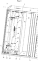
- FIG. 2 is a perspective view of another closure arrangement according to the invention for cabinet furniture 1 with a horizontally guided closure element 2 is shown.
- the cabinet 1 has in this embodiment a furniture body, consisting of a side wall 11, 12, a bottom 13, a top 14, a rear wall 15 and an additional partition 16.
- the closure element 2 is arranged in the open position OS in the cabinet 1.
- the closure element 2 is formed in this embodiment so that it has a flat decorative element 20, which has additional stiffening elements on its not visible here in the cabinet furniture 1 facing inside.
- the first guide element 3 is arranged at the end face of the bottom 13, the first guide element 3 and this opposite to the front side of the top 14, the first guide element 3 'is arranged.
- the first guide element 3, 3 ' is formed in this embodiment as a cross-sectionally approximately U-shaped rail.
- the closure element 2 is in this embodiment, with its handle element 18, through which the closure assembly 2 is movable, approximately positioned on the intermediate wall 16 of the cabinet furniture 1 and thus releases the opening 10 of the cabinet furniture 1.
- the cabinet 1 has a furniture body consisting of the bottom 13, the oppositely arranged upper floor 14, the rear wall connecting them 15 and the side wall eleventh Spaced to the side wall 11, an intermediate wall 16 is positioned between the bottom 13 and the top bottom 14.
- the rotatably arranged receiving device 4 comprising a first receiving element 5 and a second receiving element eighth
- the first receiving element 5 is arranged rotatably about a vertical axis and has at least one, not shown here, the closure element 2 at least partially receiving, horizontally arranged receiving surface 50.
- the first receiving element 5 is arranged in operative connection with the second receiving element 8.
- first receiving element 5 is arranged in operative connection with a second guide element 6.
- the second guide element 6 is fixed in this embodiment, both on the bottom 13 and on the upper floor 14 of the cabinet furniture 1 via the fastening elements 62.
- the second guide element 6 is formed in this embodiment so that it has a recess 61 in which the first receiving element 5 is arranged.
- the second guide element 6 has a guide groove 60, which is arranged adjacent to the receiving surface 50 of the first receiving element 5, wherein the first receiving element 5 is arranged in the recess 61 of the second guide member 6, that the receiving surface 50 and the guide groove 60 side by side in the same height are arranged horizontally.
- the closure arrangement according to the invention is further designed in this exemplary embodiment such that the first guide element 3 arranged on the end face of the base 13 and the first guide element 3 'arranged on the end face of the upper floor 14 are in operative connection with the guide groove 60 of the second guide element 6.
- the first receiving element 5 is designed in this embodiment so that the receiving surface 50 is formed circular and smooth surface. Furthermore, the first receiving element 5 is formed so that it is connected via the connecting element 51 with the second receiving element 8 in operative connection.
- the receiving device 4, comprising the first receiving element 5 and the second receiving element 8, is thus rotatably arranged.
- the second receiving element 8 is formed in this embodiment so that it has a housing member 80 on which two holding elements 81 are arranged.
- the second receiving element 8 is further configured, as can be seen in the partial sectional view, that it has an axis 82 and a spring element 83.
- the axis 82 is arranged fixed in the bottom 13 or in the topsoil 14 and equidistant from the housing member 80 spaced. In the space between the housing 80 and the axis 82, the spring element 83 is arranged.
- the spring element 83 is arranged with a free end on the axis 82 and with the second free end on the housing element 80, so that during a rotational movement of the receiving device 4, caused by a movement of the closure element not shown here from the open position OS the closed position GS, the spring element 83 is stretched so that it is movable in the opposite movement of the closed position GS in an open position OS, the closure element 2 solely by the force of the spring element 83.
- the trained as a force accumulator spring element 83 exerts in this embodiment, a tensile force of about 3 N on the closure element 2.
- the receiving surface 50 of the first receiving element 5 which is smooth-surfaced and circular in this embodiment, is dimensioned so that it has a diameter which corresponds to about one-third of the difference in the path between the closed position GS and the open position OS.
- the diameter of the receiving surface 50 of the first receiving element 5 is about 165 mm.
- the receiving surface 50 of the first receiving element 5 can always be dimensioned so that it fully absorbs the closure element 2, not shown here in the open position OS.
- the diameter may have values of about 100 mm to 500 mm, preferably 100 mm to 350 mm.
- the closure arrangement according to the invention is furthermore designed such that a deflection device 7 is arranged on the second guide element 6 in this exemplary embodiment.
- the deflecting device 7 has an axis 70 arranged in a guide element 63, on which a deflecting element 71, 72 is arranged.
- the deflecting element 71, 72 is rotatable and in this example in its outer contour circular designed as a wheel.
- the deflection element 71, 72 supports or stabilizes the closure element 2 and guides it via the guide groove 60 to the receiving surface 50 of the first receiving element 5th
- FIG. 4 is a detailed representation of another closure arrangement according to the invention in the cabinet 1 shown.
- the cabinet furniture 1 has a furniture body, consisting of the bottom 13, the oppositely arranged topsoil 14, the connecting rear wall 15 and the side wall 11. Spaced from the side wall 11 is between the bottom 13 and the top 14 an intermediate wall 16 is positioned.
- receiving element 8 In the area between the side wall 11 and the intermediate wall 16 of the cabinet furniture 1 designed as a force storage, rotatably arranged receiving element 8 is shown. Furthermore, the receiving element 8 is arranged in operative connection with a second guide element 6.
- the second guide element 6 is fixed in this embodiment, both on the bottom 13 and on the upper floor 14 of the cabinet furniture 1 via the fastening elements 62.
- the closure arrangement according to the invention is also designed in this exemplary embodiment such that the first guide element arranged on the end face of the floor 13 3 as well as arranged on the front side of the topsoil 14 first guide member 3 'with the guide groove 60 of the second guide member 6 are in operative connection.
- the receiving element 8 is designed such that it has a housing element 80, on which two holding elements 81 are arranged.
- the receiving element 8 is further formed so that it has an axis 82 to the second guide member 6.
- the axis 82 is arranged fixed in the bottom 13 or in the topsoil 14 and equidistant from the housing member 80 spaced. In the space between the housing 80 and the axis 82, a (non-visible) electric motor is arranged.
- the closure arrangement according to the invention is designed such that in this exemplary embodiment, a deflection device 7 is arranged on the second guide element 6.
- the deflecting device 7 has an axis 70 arranged in a guide element 63, on which a deflecting element 71, 72 is arranged.
- the deflecting element 71, 72 is rotatable and in this example in its outer contour circular designed as a wheel.
- the deflecting element 71, 72 supports or stabilizes the closure element 2 and guides it via the guide groove 60 to the receiving element 8 designed as a force accumulator ,
Landscapes
- Engineering & Computer Science (AREA)
- Structural Engineering (AREA)
- Architecture (AREA)
- Civil Engineering (AREA)
- Closing And Opening Devices For Wings, And Checks For Wings (AREA)
- Cabinets, Racks, Or The Like Of Rigid Construction (AREA)
Description
- Die Erfindung betrifft eine Verschlussanordnung insbesondere für Schrankmöbel, mit wenigstens einem horizontal geführten Verschlusselement, insbesondere Jalousie, Rollladen und dergleichen, welches im Bereich einer Öffnung des Schrankmöbels von einer geschlossenen Position in eine offene Position und zurück bewegbar angeordnet ist, mit wenigsten einem an der Öffnung des Schrankmöbels angeordneten ersten Führungselement, mit wenigstens einer drehbar angeordneten Aufnahmevorrichtung, umfassend ein erstes Aufnahmeelement sowie ein zweites Aufnahmeelement.
- Derartige Verschlussanordnungen sind im Stand der Technik bekannt.
- So beschreibt die
DE 1850550 U eine gattungsgemäße Verschlussanordnung für ein Schrankmöbel. Diese Verschlussanordnung ist als Rollladen oder rollladenähnlicher Verschluss ausgebildet, der eine an zwei gegenüberliegenden Seiten in an den Seitenwänden des Schrankmöbels ausgebildeten Führungen laufende und in Richtung der Bewegung zwischen der Offenstellung eine nachgiebige und biegsame, zusammenrollbare tragende Bahn besitzt, die während der Bewegung in Richtung auf die Offenstellung zu in einem oben oder unten oder an der Seite vorgesehenen Raum oder Kasten aufgerollt wird und eine glatte Außenfläche mit holzähnlichem Aussehen aufweist und an ihrer Innenseite mithilfe von sich quer zur Bewegungsrichtung über ihre gesamte Breite erstreckenden Versteifungsrippen oder -leisten abgesteift ist. - Dazu ist die tragende Bahn aus einer Folie oder Tafel aus Kunststoffmaterial hergestellt, in deren Innenseite die Versteifungsrippen oder -leisten so eingearbeitet sind, dass zwischen zwei aufeinanderfolgenden Rippen oder Leisten aus Kunststoffmaterial jeweils ein großer Abstand vorhanden ist und die außen direkt oder unter Zwischenschaltung von Mittelschichten eine der Verschlussaußenseite holzähnliches Aussehen verleihen und eine ununterbrochene, aus einem Stück bestehende Deckschicht trägt.
- Nachteilig bei dieser Verschlussanordnung wird gesehen, dass durch den komplexen Aufbau des Verschlusselementes die Bewegung des Öffnens bzw. des Schließens mit einer erhöhten Kraftaufwendung verbunden ist, da insbesondere das Verschlusselement in der unteren horizontal angeordneten Führungsschiene bedingt durch Reibungskräfte und Fertigungstoleranzen nicht optimal bewegbar ist.
- Eine weitere Verschlussanordnung ist in der
DE 1921182 U1 beschrieben.
Diese Verschlussanordnung für Gehäuse aller Art, insbesondere für Schrankmöbel, weist ein Verschlusselement auf, welches aus einzelnen, aneinander angeordneten Jalousieelementen, die gelenkig miteinander verbunden sind und welche von einer geschlossenen Position in eine offene Position bewegbar angeordnet sind, mit wenigstens einem an der Öffnung angeordneten Führungselement, wobei am Ende des letzten im Schrankmöbel angeordneten Jalousiestabes beidseitig Führungsteile angebracht sind, die über die Breite der Jalousie hinausragen und in vertieften Führungsnuten laufen, die kürzer sind, als die Gesamtlänge der Jalousie und das beidseitig je eine Ausnehmung vorgesehen ist, welche den Teil der Jalousie aufzunehmen vermag, der nach dem Erreichen des Anschlags der vertieften Führungsnut eingeschoben ist.
Die den Jalousiestäben der Geometrie entsprechende Führungsnut an der Öffnung des Schrankmöbels ist in dem für die Jalousie bestimmten Aufnahmeraum in ihrer Breite so ausgebildet, dass sie in der offenen Position die Jalousie aufnehmen kann.
Ab einer bestimmten Öffnung der Jalousie sind nur noch die Führungsteile in der Nut gehalten, so dass die Jalousie sich in dem Aufnahmeraum ohne nennenswerte Reibung weiterbewegen soll. - Nachteilig bei dieser Verschlussanordnung ist es, das zum Öffnen des Verschlusselementes anfänglich eine erhöhte Krafteinwirkung erforderlich ist.
- Ein weiterer Nachteil wird darin gesehen, dass durch die Fixierung des letzten Jalousiestabes in etwa an der Rückwand des Schrankmöbels die für den Verschluss der Öffnung des Schrankmöbels erforderliche Jalousie wesentlich länger sein muss, da diese sowohl die Breite des Schrankes zur geschlossenen Position abdecken und gleichzeitig aber noch in die Tiefe des Schrankes bis zu der Arretierung des letzten Profilstabes angeordnet sein muss. Dies führt zu höheren Herstellungskosten der Jalousie und auch zu erhöhtem Montageaufwand der Verschlussanordnung in dem Schrankmöbel.
- Die
JP 2009 185576 A
Es wird weiterhin offenbart, dass die Aufnahmefläche vertikal und nicht horizontal angeordnet ist. Demzufolge ist auch die Achse horizontal angeordnet. Weiterhin wird auch die Möglichkeit offenbart, an den eingebauten und verschlossenen Rollladenkasten mithilfe einer bewegbar angeordneten Klappe zu Reparatur- bzw. Ersatzzwecken jederzeit heranzukommen. - Hier setzt die Erfindung ein, die sich die Aufgabe gestellt hat, die Nachteile des bekannten Standes der Technik zu überwinden und eine Verschlussanordnung aufzuzeigen, die wirtschaftlich und kostengünstig herstellbar ist, die bei bestimmungsgemäßem Gebrauch jederzeit ein gleichmäßiges Laufverhalten mit reduzierter Bedienungskraft ermöglicht.
- Erfindungsgemäß wird diese Aufgabe durch eine Verschlussanordnung gemäß den Merkmalen des Anspruches 1 realisiert.
Vorteilhafte Ausgestaltungen sind in den Unteransprüchen beschrieben. - Es konnte überraschend festgestellt werden, dass eine Verschlussanordnung insbesondere für Schrankmöbel, mit wenigstens einem horizontal geführten Verschlusselement, insbesondere Jalousie, Rollladen und dergleichen, welches im Bereich einer Öffnung des Schrankes von einer geschlossenen Position in eine offene Position und zurück bewegbar angeordnet ist, mit wenigstens einem an der Öffnung des Schrankmöbels angeordneten ersten Führungselement, mit wenigstens einer drehbar angeordneten Aufnahmevorrichtung, umfassend ein erstes Aufnahmeelement sowie ein zweites Aufnahmeelement, sich dadurch auszeichnet, dass das erste Aufnahmeelement um eine vertikale Achse drehbar angeordnet ist und das es wenigstens eine, das Verschlusselement wenigstens teilweise aufnehmende, horizontal angeordnete, Aufnahmefläche aufweist. Durch diese erfindungsgemäße Verschlussanordnung ist es somit erstmals möglich, das Öffnen bzw. Schließen von Schrankmöbeln mit horizontal geführten Verschlusselementen so zu realisieren, dass bei der Bewegung des Verschlusselementes nahezu keine Reibungsverluste in den Führungselementen auftreten und sich das Verschlusselement sehr leicht und ohne große Krafteinwirkung von einer geschlossenen Position in eine offene Position und zurück bewegen lässt.
Das erste Aufnahmeelement ist dabei vorteilhafterweise so ausgebildet, dass es eine beispielsweise im Querschnitt runde Aufnahmefläche aufweist, auf die das Verschlusselement bei der Bewegung von einer geschlossenen Position in eine offene Position aufnehmbar ist und die durch das Gewicht des Verschlusselementes und die Materialpaarungen des Verschlusselementes sowie des Führungselementes sich ergebenden Reibungsverluste minimiert sind. Die erfindungsgemäße Verschlussanordnung führt somit insbesondere mit dem drehbar angeordneten ersten Aufnahmeelement dazu, dass das Gewicht des Verschlusselementes bei der Bewegung von einer geschlossenen Position in eine offene Position über die Aufnahmefläche des ersten Aufnahmeelementes aufgenommen ist und somit die Öffnungs- bzw. Schließbewegung des Verschlusselementes sehr leicht realisierbar ist.
Es hat sich weiterhin als vorteilhaft herausgestellt, dass das erste Aufnahmeelement mit dem zweiten Aufnahmeelement in Wirkverbindung steht. Hierdurch ist es einerseits möglich, das Verschlusselement am zweiten Aufnahmeelement so anzuordnen, dass bei einer Bewegung von einer geschlossenen Position in eine offene Position und zurück das Verschlusselement um das zweite Aufnahmeelement durch die rotierende Bewegung des ersten Aufnahmeelements wickelbar ist. - In einer weiteren vorteilhaften Ausgestaltung der erfindungsgemäßen Verschlussanordnung steht das erste Aufnahmeelement mit dem zweiten Führungselement in Wirkverbindung. Dieses zweite Führungselement der erfindungsgemäßen Verschlussanordnung ist beispielsweise am Boden des Schrankmöbels bzw. am Oberboden des Schrankmöbels positioniert und nimmt das erste Aufnahmeelement auf.
Hierzu kann vorteilhafterweise das erste Aufnahmeelement in einer Vertiefung des zweiten Führungselementes angeordnet sein. Diese vorteilhafte Anordnung ist kostengünstig und wirtschaftlich herstellbar und führt dazu, dass das erste Aufnahmeelement im zweiten Führungselement drehbar anordenbar ist. - Ein weiterer Vorteil der erfindungsgemäßen Verschlussanordnung besteht darin, dass die Aufnahmefläche des ersten Aufnahmeelementes benachbart zu einer Führungsnut des zweiten Führungselements angeordnet ist. Diese Führungsnut ist vorteilhafterweise so ausgebildet, dass die an ihrem einen freien Ende mit dem ersten Führungselement in Wirkverbindung steht und mit ihrem zweiten freien Ende mit dem ersten Aufnahmeelement in Wirkverbindung steht. Das Verschlusselement ist somit aus der geschlossenen Position über das erste Führungselement bis zur Führungsnut des zweiten Führungselements bewegbar, wobei die Führungsnut des zweiten Führungselementes dazu dient, das Verschlusselement an bzw. auf die Aufnahmefläche des ersten Aufnahmeelementes zu führen. Es liegt jedoch auch im Rahmen der Erfindung, dass die erfindungsgemäße Verschlussanordnung ohne ein derartiges zweites Führungselement realisierbar ist.
- Eine weitere vorteilhafte Ausgestaltung der erfindungsgemäßen Verschlussanordnung sieht vor, dass das erste Aufnahmeelement über ein Verbindungselement mit dem zweiten Aufnahmeelement in Wirkverbindung steht. Diese vorteilhafte Ausgestaltung ist kostengünstig herstellbar und führt zu einer schnellen und einfachen Montage der drehbar angeordneten Aufnahmevorrichtung.
- Es hat sich weiterhin als sehr vorteilhaft herausgestellt, dass die Aufnahmefläche des ersten Aufnahmeelementes glattflächig ausgebildet ist. Hierdurch ist es möglich, verschiedenste Arten von Verschlusselementen wie beispielsweise Jalousien, Rollladen und dergleichen problemlos auf die Aufnahmefläche des ersten Aufnahmeelementes zu führen bzw. zu transportieren.
- Es liegt weiterhin auch im Rahmen der Erfindung, dass die Aufnahmefläche des ersten Aufnahmeelementes im Querschnitt etwa U-förmige Nuten zur Aufnahme des Verschlusselements aufweist. In dieser vorteilhaften Ausgestaltung ist es somit möglich, dass Verschlusselement vom ersten Führungselement über die Führungsnut des zweiten Führungselementes in die U-förmigen Nuten des ersten Aufnahmeelementes zu überführen und so für eine kraftarme Bewegung des Verschlusselementes von einer geschlossenen Position in eine offene Position und zurück, zu realisieren.
- In einer weiteren vorteilhaften Ausgestaltung der erfindungsgemäßen Verschlussanordnung weist das zweite Aufnahmeelement wenigstens eine Welle auf, die drehbar im Schrankmöbel angeordnet ist. Diese Welle ist dabei so ausgebildet, dass sie leicht drehbar angeordnet ist und so in ihren Maßen dimensioniert ist, dass ein daran angeordnetes Verschlusselement vollumfänglich aufnehmbar ist. Es liegt weiterhin im Rahmen der Erfindung, dass das zweite Aufnahmeelement so ausgebildet ist, dass es eine Achse aufweist die beispielsweise im zweiten Führungselement fixiert ist und um welche das zweite Aufnahmeelement drehbar gelagert angeordnet ist.
- Die erfindungsgemäße Verschlussanordnung ist weiterhin so ausgebildet, dass das zweite Aufnahmeelement wenigstens ein Halteelement aufweist. Hierdurch ist es vorteilhafterweise möglich, verschiedenste Arten, Größen und Geometrien von Verschlusselementen am zweiten Aufnahmeelement zu fixieren, so dass das Verschlusselement bei der Bewegung von einer geschlossenen Position in eine offene Position und zurück leicht und mit minimalem Kraftaufwand bewegbar ist.
- Die erfindungsgemäße Verschlussanordnung ist weiterhin so ausgebildet, dass die Aufnahmefläche des ersten Aufnahmeelementes so dimensioniert ist, dass sie das Verschlusselement in der offenen Position vollumfänglich aufnimmt. Das am zweiten Aufnahmeelemente fixierte Verschlusselement wird somit durch die Drehbewegung des ersten Aufnahmeelementes auf die Aufnahmefläche des ersten Aufnahmeelementes befördert und durch die weitere Drehbewegung um das zweite Aufnahmeelement radial aufgewickelt, bis die Öffnung des Schrankmöbels komplett freigegeben ist. Die Aufnahmefläche des ersten Aufnahmeelementes kann dabei im Querschnitt kreisförmig ausgebildet sein und einen Durchmesser aufweisen, der etwa einem Drittel der Differenz zwischen der geschlossenen Position GS und der offenen Position OS der Verschlussanordnung entspricht
- Es hat sich ebenfalls als vorteilhaft herausgestellt, dass am zweiten Führungselement eine Umlenkvorrichtung angeordnet ist, die dafür sorgt, dass das horizontal geführte Verschlusselement bei seiner Bewegung von einer geschlossenen Position in eine offene Position sowie zurück stabil geführt ist und von einer linearen Bewegung im ersten Führungselement in eine gebogene Bewegung in der Führungsnut des zweiten Führungselementes führbar und stabilisierbar ist.
- Dabei hat es sich weiterhin als sehr vorteilhaft herausgestellt, dass die Umlenkvorrichtung eine in einem Führungselement des zweiten Führungselementes angeordnete Welle aufweist, an der wenigstens ein Umlenkelement angeordnet ist. Es liegt ebenfalls im Rahmen der Erfindung, dass die Umlenkvorrichtung an einer im zweiten Führungselement fixierten Achse angeordnet ist. Dieses beispielsweise kreisförmig ausgebildete Umlenkelement lässt sich dabei so dimensionieren, dass verschiedenste Arten, Geometrien bzw. Materialien von Verschlusselementen der erfindungsgemäßen Verschlussanordnung leicht und sicher bewegbar angeordnet werden können.
- Die erfindungsgemäße Verschlussanordnung zeichnet sich weiterhin dadurch aus, dass das zweite Aufnahmeelement ein um die Welle angeordnetes Gehäuseelement aufweist, welches über ein Federelement mit der Welle in Wirkverbindung steht. Es liegt ebenfalls im Rahmen der Erfindung, dass das zweite Aufnahmeelement an einer im zweiten Führungselement fixierten Achse angeordnet ist. Durch diese vorteilhafte Ausgestaltung der erfindungsgemäßen Verschlussanordnung ist es möglich, dass die Bewegung des horizontal geführten Verschlusselementes von einer geschlossenen Position in eine offene Position und zurück durch die Kraft des Federelements im zweiten Aufnahmeelement realisierbar ist. Das Öffnen bzw. Schließen des im Schrankmöbel horizontal angeordneten Verschlusselementes kann dadurch vorteilhafterweise so erfolgen, dass der jeweilige Nutzer das Verschlusselement von der geschlossenen Position nur kurz antippt und durch die Kraft des Federelements im zweiten Aufnahmeelement sich das Verschlusselement allein über das erste Führungselement in die Führungsnut des zweiten Führungselements auf die Aufnahmefläche des ersten Aufnahmeelementes bewegt. Es liegt jedoch auch im Rahmen der Erfindung, dass das zweite Aufnahmeelement ein um die Welle angeordnetes Gehäuseelement aufweist, welches über einen an sich bekannten Elektromotor mit der Welle in Wirkverbindung steht. Der Elektromotor, dient dazu, dass das Verschlusselement von der geschlossenen Position GS in die offene Position OS ohne zusätzlichen Kraftaufwand des Benutzer bewegbar ist. Weiterhin lässt die Anordnung eines Elektromotors im Gehäuseelement des zweiten Aufnahmeelementes es zu, dass das Verschlusselement auch von der offenen Position OS über die Kraft des Elektromotors in die geschlossene Position GS überführbar ist.
- Es konnte weiterhin überraschend festgestellt werden, dass eine Verschlussanordnung insbesondere für Schrankmöbel, mit wenigstens einem Verschlusselement an dem wenigstens ein Griffelement angeordnet ist, insbesondere Jalousie, Rollladen und dergleichen, welches im Bereich einer Öffnung des Schrankmöbels von einer geschlossenen Position in eine offene Position und zurück bewegbar ist, mit wenigstens einem an der Öffnung des Schrankmöbels angeordneten ersten Führungselement sowie mit wenigstens einem Kraftspeicher sich dadurch auszeichnet, dass der Kraftspeicher in Wirkverbindung mit dem Verschlusselement steht.
Weiterhin vorteilhaft bei der erfindungsgemäßen Verschlussanordnung ist, dass der Kraftspeicher so ausgebildet ist, dass der Kraftspeicher in Wirkverbindung mit wenigstens einem Profilelement des Verschlusselementes steht.
Ebenfalls hat sich bei der erfindungsgemäßen Verschlussanordnung vorteilhaft herausgestellt, dass der Kraftspeicher so ausgebildet ist, dass der Kraftspeicher in Wirkverbindung mit dem dem Griffelement gegenüberliegenden freien Ende des Verschlusselementes steht.
Durch diese erfindungsgemäße Verschlussanordnung ist es somit erstmals möglich, das Öffnen bzw. Schließen von Schrankmöbeln mit geführten Verschlusselementen so zu realisieren, dass bei der Bewegung des Verschlusselementes nahezu keine Reibungsverluste in den Führungselementen auftreten und sich das Verschlusselement sehr leicht und ohne die Krafteinwirkung des Benutzers von einer geschlossenen Position in eine offene Position und zurück bewegen lässt. - Dabei hat sich weiterhin als sehr vorteilhaft herausgestellt bei der erfindungsgemäßen Verschlussanordnung, dass der Kraftspeicher so ausgebildet ist, dass er das Verschlusselement ständig mit einer Zugkraft belastet. Hierdurch ist gewährleistet, dass Schrankmöbel verschiedenster Größer mit der erfindungsgemäßen Verschlussanordnung versehen werden können, so dass hier immer ein selbständiges Öffnen bzw. Schließen der Verschlusselement realisierbar ist.
- In einer vorteilhaften Ausgestaltung der erfindungsgemäßen Verschlussanordnung ist der Kraftspeicher als Elektromotor ausgebildet. In dieser vorteilhaften Ausgestaltung lässt sich die erfindungsgemäße Verschlussanordnung gleichmäßig und leicht von der geschlossenen Position in eine offene Position und zurück jederzeit bewegen. Dabei kann der als Kraftspeicher ausgebildete Elektromotor ein Drehmoment von 3 Nm bis 80 Nm, vorzugsweise 5 Nm bis 50 Nm aufweisen.
- In einer ebenfalls vorteilhaften Ausgestaltung der erfindungsgemäßen Verschlussanordnung ist der Kraftspeicher als Aufnahmeelement umfassend eine Welle, wenigstens ein Federelement sowie ein Gehäuseelement, ausgebildet. In dieser vorteilhaften Ausgestaltung lässt sich die erfindungsgemäße Verschlussanordnung kostengünstig und wirtschaftlich herstellen und eine leichte Bewegung des Verschlusselementes von der geschlossenen Position in eine offene Position und zurück ist jederzeit gewährleistet.
- Es hat sich weiterhin als vorteilhaft herausgestellt, dass das als Kraftspeicher ausgebildete Federelement eine Kraft von etwa 1 N bis 80 N, vorzugsweise 5 N bis 50 N auf das Verschlusselement ausübt. Durch diese Dimensionierung ist es erstmals möglich, verschiedene Breiten bzw. Höhen von Schränken mit erfindungsgemäßen Verschlussanordnungen zu versehen, die durch den Kraftspeicher jederzeit problemlos und ohne zusätzlichen Aufwand durch den Benutzer von einer geschlossenen Position in eine offene Position und zurück bewegbar sind.
- Die erfindungsgemäße Verschlussanordnung ist weiterhin so ausgebildet, dass das Griffelement des Verschlusselementes wenigstens ein Fixierelement aufweist. Durch diese Ausgestaltung kann die erfindungsgemäße Verschlussanordnung insbesondere in Schrankmöbeln in der geschlossenen Position fixiert werden, ohne das die durch den Kraftspeicher auf das Verschlusselement wirkende Zugkraft eine selbständige und vom Benutzer nicht gewollte Öffnung von der geschlossenen Position in die offene Position realisieren kann. Das Fixierelement kann dabei als Magnet mit einer metallischer Halterung oder auch als Schloss mit einem daran angeordneten beweglichen Riegel ausgebildet sein. Dabei hat es sich weiterhin als vorteilhaft herausgestellt, dass der Kraftspeicher wenigstens ein, das dem Griffelement gegenüberliegende freie Ende der Verschlussanordnung aufnehmendes Halteelement aufweist. Hierdurch ist es vorteilhafterweise möglich, verschiedene Arten, Größen und Geometrien von Verschlusselementen am Aufnahmeelement zu fixieren, so dass das Verschlusselement bei der Bewegung von der geschlossenen Position in eine offene Position und zurück sehr leicht und ohne zusätzlichen Kraftaufwand bewegbar ist.
- Dabei hat es sich weiterhin als vorteilhaft herausgestellt, dass der Kraftspeicher so ausgebildet ist, dass er die Verschlussanordnung in der offenen Position vollumfänglich aufnehmen kann. Hierzu sind vorteilhafterweise am Gehäuseelement des Aufnahmeelementes 8 entsprechend dimensionierte Halteelemente positioniert.
- Die erfindungsgemäße Verschlussanordnung ist weiterhin vorteilhafterweise so ausgebildet, dass an den Stirnseiten des Bodens bzw. des Oberbodens bzw. in den Seitenwänden jeweils weitere Führungselemente angeordnet sind, die es vorteilhafterweise ermöglichen, dass das Verschlusselement nicht in einem separaten durch eine Zwischenwand von der Seitenwand bzw. des Oberbodens abgetrennten Bereiches des Schrankmöbels positionierbar sind sondern das die Verschlussanordnung durch den Kraftspeicher in diese etwa parallel zu den ersten Führungselementen angeordneten dritten Führungselemente bewegbar ist. Insbesondere bei Schrankmöbeln, bei denen das gesamte Schrankvolumen für den Benutzer wichtig ist, kann die erfindungsgemäße Verschlussanordnung auch in dritten Führungselementen, welche hinter der Rückwand angeordnet sind positioniert werden, so dass das komplette Volumen des Schrankmöbels nutzbar ist. Diese Art der erfindungsgemäßen Verschlussanordnung ist sowohl bei vertikal geführten als auch bei horizontal geführten Verschlusselementen realisierbar.
Es hat sich weiterhin als sehr vorteilhaft herausgestellt, dass das zweite Führungselement glattflächig ausgebildet ist. Hierdurch ist es möglich, verschiedenste Arten von Verschlusselementen wie beispielsweise Jalousien, Rollladen und dergleichen problemlos auf die Aufnahmefläche des ersten Aufnahmeelementes zu führen bzw. zu transportieren. - In einer weiteren vorteilhaften Ausgestaltung der erfindungsgemäßen Verschlussanordnung weist das Aufnahmeelement wenigstens eine Welle auf, die drehbar im Schrankmöbel angeordnet ist. Diese Welle ist dabei so ausgebildet, dass sie leicht drehbar angeordnet ist und so in ihren Maßen dimensioniert ist, dass ein daran angeordnetes Verschlusselement vollumfänglich aufnehmbar ist. Es liegt weiterhin im Rahmen der Erfindung, dass das Aufnahmeelement so ausgebildet ist, dass es eine Achse aufweist die beispielsweise im zweiten Führungselement fixiert ist und um welche das zweite Aufnahmeelement drehbar gelagert angeordnet ist.
- Es hat sich ebenfalls als vorteilhaft herausgestellt, dass am zweiten Führungselement eine Umlenkvorrichtung angeordnet ist, die dafür sorgt, dass das horizontal geführte Verschlusselement bei seiner Bewegung von einer geschlossenen Position in eine offene Position sowie zurück stabil geführt ist und von einer linearen Bewegung im ersten Führungselement in eine gebogene Bewegung in der Führungsnut des zweiten Führungselementes führbar und stabilisierbar ist.
- Dabei hat es sich weiterhin als sehr vorteilhaft herausgestellt, dass die Umlenkvorrichtung eine in einem Führungselement des zweiten Führungselementes angeordnete Welle aufweist, an der wenigstens ein Umlenkelement angeordnet ist. Es liegt ebenfalls im Rahmen der Erfindung, dass die Umlenkvorrichtung an einer im zweiten Führungselement fixierten Achse angeordnet ist. Dieses beispielsweise kreisförmig ausgebildete Umlenkelement lässt sich dabei so dimensionieren, dass verschiedenste Arten, Geometrien bzw. Materialien von Verschlusselementen der erfindungsgemäßen Verschlussanordnung leicht und sicher bewegbar angeordnet werden können.
- Die erfindungsgemäße Verschlussanordnung zeichnet sich weiterhin dadurch aus, dass das Aufnahmeelement ein um die Welle angeordnetes Gehäuseelement aufweist, welches über ein Federelement mit der Welle in Wirkverbindung steht. Es liegt ebenfalls im Rahmen der Erfindung, dass das zweite Aufnahmeelement an einer im zweiten Führungselement fixierten Achse angeordnet ist. Durch diese vorteilhafte Ausgestaltung der erfindungsgemäßen Verschlussanordnung ist es möglich, dass die Bewegung des horizontal geführten Verschlusselementes von einer geschlossenen Position in eine offene Position und zurück durch die Kraft des Federelements im Aufnahmeelement realisierbar ist.
Das Öffnen bzw. Schließen des im Schrankmöbel horizontal angeordneten Verschlusselementes kann dadurch vorteilhafterweise so erfolgen, dass der jeweilige Nutzer das Verschlusselement von der geschlossenen Position nur kurz antippt und durch die Kraft des Federelements im zweiten Aufnahmeelement sich das Verschlusselement allein über das erste Führungselement in die Führungsnut des zweiten Führungselements auf die Aufnahmefläche des ersten Aufnahmeelementes bewegt. Es liegt jedoch auch im Rahmen der Erfindung, dass das zweite Aufnahmeelement ein um die Welle angeordnetes Gehäuseelement aufweist, welches über einen an sich bekannten Elektromotor mit der Welle in Wirkverbindung steht. Der Elektromotor, dient dazu, dass das Verschlusselement von der geschlossenen Position GS in die offene Position OS ohne zusätzlichen Kraftaufwand des Benutzers bewegbar ist. Weiterhin lässt die Anordnung eines Elektromotors im Gehäuseelement des zweiten Aufnahmeelementes es zu, dass das Verschlusselement auch von der offenen Position OS über die Kraft des Elektromotors in die geschlossene Position GS überführbar ist. - Die Erfindung beansprucht auch ein Schrankmöbel, welches mit einer Verschlussanordnung gemäß den vorherigen Merkmalen ausgerüstet ist.
- Die erfindungsgemäße Verschlussanordnung soll nun an Ausführungsbeispielen, die diese nicht einschränken, näher beschrieben werden.
- Es zeigen:
- Fig. 1:
- perspektivische Darstellung der erfindungsgemäßen Verschlussanordnung für Schrankmöbel
- Fig. 2:
- perspektivische Darstellung einer weiteren erfindungsgemäßen Verschlussanordnung für Schrankmöbel
- Fig. 3:
- detaillierte Darstellung der erfindungsgemäßen Verschlussanordnung
- Fig. 4:
- detaillierte Darstellung einer weiteren erfindungsgemäßen Verschlussanordnung
- In der
Fig. 1 ist eine Verschlussanordnung für ein Schrankmöbel 1 dargestellt mit einem horizontal geführten Verschlusselement 2, welches in diesem Ausführungsbeispiel als Rollladen ausgebildet ist.
Das Verschlusselement 2 besteht aus einer Vielzahl von einzelnen Profilelementen 22, die in an sich bekannter Art und Weise miteinander drehbeweglich verbunden sind. - Der Seitenwand 12 gegenüber angeordnet ist das Griffelement 18, durch welches die Verschlussanordnung 2 bewegbar ist.
Die Verschlusselement 2 ist in diesem Ausführungsbeispiel so angeordnet, dass es in der geschlossenen Position GS die nicht sichtbare Öffnung 10 des Schrankmöbels 1 verschließt.
Der Schrankmöbel 1 weist in diesem Ausführungsbeispiel einen Korpus auf bestehend aus den Seitenwänden 11, 12, einem Oberboden 14, einer Rückwand 15 sowie einem nicht sichtbaren Boden 13.
Das Verschlusselement 2 ist in diesem Ausführungsbeispiel von der geschlossenen Position GS in eine offene Position OS und zurück bewegbar angeordnet in einem Führungselement 3, 3', welches an jeweils zwei gegenüberliegend angeordneten Stirnseiten des Bodens 13 bzw. des Oberboden 14 des Schrankmöbels 1 positioniert sind.
An der Stirnseite des Bodens 13 ist das erste Führungselement 3 und am Oberboden 14 das erste Führungselement 3' angeordnet. Der Schrankmöbel 1 ist weiterhin so ausgebildet, dass an der Seitenwand 11 ein Abdeckelement 9 angeordnet ist. - In der
Fig. 2 ist eine perspektivische Darstellung einer weiteren erfindungsgemäßen Verschlussanordnung für Schrankmöbel 1 mit einem horizontal geführten Verschlusselement 2 dargestellt.
Der Schrankmöbel 1 weist in diesem Ausführungsbeispiel einen Möbelkorpus auf, bestehend aus einer Seitenwand 11, 12, einem Boden 13, einem Oberboden 14, einer Rückwand 15 sowie einer zusätzlichen Zwischenwand 16. - In diesem Ausführungsbeispiel ist das Verschlusselement 2 in der offenen Position OS im Schrankmöbel 1 angeordnet.
Das Verschlusselement 2 ist in diesem Ausführungsbeispiel so ausgebildet, dass es ein flächiges Dekorelement 20 aufweist, welches an seiner hier nicht sichtbaren in den Schrankmöbel 1 weisenden Innenseite zusätzliche Versteifungselemente aufweist. - An der Stirnseite des Bodens 13 ist das erste Führungselement 3 und diesem gegenüberliegend an der Stirnseite des Oberbodens 14 das erste Führungselement 3' angeordnet. Das erste Führungselement 3, 3' ist in diesem Ausführungsbeispiel als im Querschnitt etwa U-förmige Schiene ausgebildet.
Das Verschlusselement 2 ist in diesem Ausführungsbeispiel mit seinem Griffelement 18, durch welches die Verschlussanordnung 2 bewegbar ist, etwa an der Zwischenwand 16 des Schrankmöbels 1 positioniert und gibt somit die Öffnung 10 des Schrankmöbels 1 frei. - In der
Fig. 3 ist eine Detaildarstellung der erfindungsgemäßen Verschlussanordnung im Schrankmöbel 1 dargestellt.
Der Schrankmöbel 1 weist einen Möbelkorpus auf bestehend aus dem Boden 13, dem gegenüberliegend angeordneten Oberboden 14, den diese verbindende Rückwand 15 sowie die Seitenwand 11.
Beabstandet zur Seitenwand 11 ist zwischen dem Boden 13 und dem Oberboden 14 eine Zwischenwand 16 positioniert. - In dem Bereich zwischen der Seitenwand 11 und der Zwischenwand 16 des Schrankmöbels 1 ist die drehbar angeordnete Aufnahmevorrichtung 4 dargestellt, umfassend ein erstes Aufnahmeelement 5 sowie ein zweites Aufnahmeelement 8.
Das erste Aufnahmeelement 5 ist um eine vertikale Achse drehbar angeordnet und weist wenigstens eine, das hier nicht dargestellte Verschlusselement 2 wenigstens teilweise aufnehmende, horizontal angeordnete Aufnahmefläche 50 auf.
In diesem Ausführungsbeispiel ist das erste Aufnahmeelement 5 mit dem zweiten Aufnahmeelement 8 in Wirkverbindung stehend angeordnet. - Weiterhin ist das erste Aufnahmeelement 5 mit einem zweiten Führungselement 6 in Wirkverbindung stehend angeordnet. Das zweite Führungselement 6 ist in diesem Ausführungsbeispiel sowohl am Boden 13 als auch am Oberboden 14 des Schrankmöbels 1 über die Befestigungselemente 62 fixiert. Das zweite Führungselement 6 ist in diesem Ausführungsbeispiel so ausgebildet, dass es eine Vertiefung 61 aufweist, in der das erste Aufnahmeelement 5 angeordnet ist.
- Weiterhin weist das zweite Führungselement 6 eine Führungsnut 60 auf, die benachbart zur Aufnahmefläche 50 des ersten Aufnahmeelements 5 angeordnet ist, wobei das erste Aufnahmeelement 5 so in der Vertiefung 61 des zweiten Führungselements 6 angeordnet ist, dass die Aufnahmefläche 50 und die Führungsnut 60 nebeneinander in gleicher Höhe liegend angeordnet sind.
- Die erfindungsgemäße Verschlussanordnung ist in diesem Ausführungsbeispiel weiterhin so ausgebildet, dass das an der Stirnseite des Bodens 13 angeordnete erste Führungselement 3 sowie das an der Stirnseite des Oberbodens 14 angeordnete erste Führungselement 3' mit der Führungsnut 60 des zweiten Führungselementes 6 in Wirkverbindung stehen.
Das erste Aufnahmeelement 5 ist in diesem Ausführungsbeispiel so ausgestaltet, dass die Aufnahmefläche 50 kreisförmig und glattflächig ausgebildet ist.
Weiterhin ist das erste Aufnahmeelement 5 so ausgebildet, dass es über das Verbindungselement 51 mit dem zweiten Aufnahmeelement 8 in Wirkverbindung steht.
Die Aufnahmevorrichtung 4, umfassend das erste Aufnahmeelement 5 sowie das zweite Aufnahmeelement 8, ist somit drehbar angeordnet. - Das zweite Aufnahmeelement 8 ist in diesem Ausführungsbeispiel so ausgebildet, dass es ein Gehäuseelement 80 aufweist an dem zwei Halteelemente 81 angeordnet sind.
Das zweite Aufnahmeelement 8 ist weiterhin so ausgebildet, wie in der Teilschnittdarstellung erkennbar, dass es eine Achse 82 sowie ein Federelement 83 aufweist.
Die Achse 82 ist dabei im Boden 13 bzw. im Oberboden 14 fixiert angeordnet und äquidistant vom Gehäuseelement 80 beabstandet.
Im Zwischenraum zwischen dem Gehäuse 80 und der Achse 82 ist das Federelement 83 angeordnet. In diesem Ausführungsbeispiel ist das Federelement 83 mit einem freien Ende an der Achse 82 und mit dem zweiten freien Ende am Gehäuseelement 80 angeordnet, so dass bei einer Drehbewegung der Aufnahmevorrichtung 4, verursacht durch eine Bewegung des hier nicht dargestellten Verschlusselementes von der offenen Position OS in die geschlossene Position GS das Federelement 83 so gespannt ist, dass es bei der entgegengesetzten Bewegung von der geschlossenen Position GS in eine offene Position OS das Verschlusselement 2 allein durch die Kraft des Federelements 83 bewegbar ist.
Das als Kraftspeicher ausgebildete Federelement 83 übt in diesem Ausführungsbeispiel eine Zugkraft von etwa 3 N auf das Verschlusselement 2 aus. - Die Aufnahmefläche 50 des ersten Aufnahmeelements 5, welche in diesem Ausführungsbeispiel glattflächig und kreisförmig ausgebildet ist, ist so dimensioniert, dass sie einen Durchmesser aufweist, der etwa einem Drittel der Differenz des Weges zwischen der geschlossenen Position GS und der offenen Position OS entspricht. In diesem Ausführungsbeispiel beträgt der Durchmesser der Aufnahmefläche 50 des ersten Aufnahmeelementes 5 etwa 165 mm.
- Somit kann die Aufnahmefläche 50 des ersten Aufnahmeelements 5 immer so dimensioniert sein, dass es das hier nicht dargestellte Verschlusselement 2 in der offenen Position OS vollumfänglich aufnimmt. Der Durchmesser kann dabei Werte von etwa 100 mm bis 500 mm, bevorzugt 100 mm bis 350 mm aufweisen.
Die erfindungsgemäße Verschlussanordnung ist weiterhin so ausgebildet, dass in diesem Ausführungsbeispiel am zweiten Führungselement 6 eine Umlenkvorrichtung 7 angeordnet ist.
Die Umlenkvorrichtung 7 weist in diesem Ausführungsbeispiel eine in einem Führungselement 63 angeordnete Achse 70 auf, an der ein Umlenkelement 71, 72 angeordnet ist. Das Umlenkelement 71, 72 ist drehbar und in diesem Beispiel in seiner Außenkontur kreisförmig als Rad ausgebildet. - Bei einer Bewegung des Verschlusselementes 2 vom ersten Führungselement 3, 3' in die Führungsnut 60 des zweiten Führungselements 6 stützt bzw. stabilisiert das Umlenkelement 71, 72 das Verschlusselement 2 und führt es über die Führungsnut 60 zur bzw. auf die Aufnahmefläche 50 des ersten Aufnahmeelementes 5.
- In der
Fig. 4 ist eine Detaildarstellung einer weiteren erfindungsgemäßen Verschlussanordnung im Schrankmöbel 1 dargestellt. - Der Schrankmöbel 1 weist einen Möbelkorpus auf, bestehend aus dem Boden 13, dem gegenüberliegend angeordneten Oberboden 14, den diese verbindende Rückwand 15 sowie die Seitenwand 11. Beabstandet zur Seitenwand 11 ist zwischen dem Boden 13 und dem Oberboden 14 eine Zwischenwand 16 positioniert.
- In dem Bereich zwischen der Seitenwand 11 und der Zwischenwand 16 des Schrankmöbels 1 ist das als Kraftspeicher ausgebildete, drehbar angeordnete Aufnahmeelement 8 dargestellt.
Weiterhin ist das Aufnahmeelement 8 mit einem zweiten Führungselement 6 in Wirkverbindung stehend angeordnet.
Das zweite Führungselement 6 ist in diesem Ausführungsbeispiel sowohl am Boden 13 als auch am Oberboden 14 des Schrankmöbels 1 über die Befestigungselemente 62 fixiert. - Die erfindungsgemäße Verschlussanordnung ist in diesem Ausführungsbeispiel weiterhin so ausgebildet, dass das an der Stirnseite des Bodens 13 angeordnete erste Führungselement 3 sowie das an der Stirnseite des Oberbodens 14 angeordnete erste Führungselement 3' mit der Führungsnut 60 des zweiten Führungselementes 6 in Wirkverbindung stehen.
Das Aufnahmeelement 8 ist so ausgebildet, dass es ein Gehäuseelement 80 aufweist, an dem zwei Halteelemente 81 angeordnet sind.
Das Aufnahmeelement 8 ist weiterhin so ausgebildet, dass es eine Achse 82 zum zweiten Führungselement 6 aufweist. Die Achse 82 ist dabei im Boden 13 bzw. im Oberboden 14 fixiert angeordnet und äquidistant vom Gehäuseelement 80 beabstandet.
Im Zwischenraum zwischen dem Gehäuse 80 und der Achse 82 ist ein (nicht sichtbarer) Elektromotor angeordnet. Dieser fungiert als Kraftspeicher und bewegt das hier nur teilweise dargestellte Verschlusselement 2 von der offenen Position OS in die geschlossene Position GS und weist ein Drehmoment von etwa 10 Nm auf.
Die erfindungsgemäße Verschlussanordnung ist so ausgebildet, dass in diesem Ausführungsbeispiel am zweiten Führungselement 6 eine Umlenkvorrichtung 7 angeordnet ist. Die Umlenkvorrichtung 7 weist in diesem Ausführungsbeispiel eine in einem Führungselement 63 angeordnete Achse 70 auf, an der ein Umlenkelement 71, 72 angeordnet ist.
Das Umlenkelement 71, 72 ist drehbar und in diesem Beispiel in seiner Außenkontur kreisförmig als Rad ausgebildet.
Bei einer Bewegung des hier nur teilweise dargestellten Verschlusselementes 2 vom ersten Führungselement 3, 3' in die Führungsnut 60 des zweiten Führungselements 6 stützt bzw. stabilisiert das Umlenkelement 71, 72 das Verschlusselement 2 und führt es über die Führungsnut 60 zum als Kraftspeicher ausgebildeten Aufnahmeelement 8.
Claims (20)
- Verschlussanordnung insbesondere für Schrankmöbel (1), mit wenigstens einem horizontal geführten Verschlusselement (2), insbesondere Jalousie, Rollladen und dergleichen, welches im Bereich einer Öffnung (10) des Schrankmöbels (1) von einer geschlossenen Position (GS) in eine offene Position (OS) und zurück bewegbar angeordnet ist, mit wenigstens einem an der Öffnung (10) des Schrankmöbels (1) angeordneten ersten Führungselement (3, 3'), mit wenigstens einer drehbar angeordneten Aufnahmevorrichtung (4), umfassend ein erstes Aufnahmeelement (5) sowie ein zweites Aufnahmeelement (8), wobei das erste Aufnahmeelement (5) um eine vertikale Achse drehbar angeordnet ist und das es wenigstens eine, das Verschlusselement (2) wenigstens teilweise aufnehmende, horizontal angeordnete, Aufnahmefläche (50) aufweist, dadurch gekennzeichnet, dass das erste Aufnahmeelement (5) mit einem zweiten Führungselement (6) in Wirkverbindung steht, dass das erste Aufnahmeelement (5) in einer Vertiefung (61) des zweiten Führungselements (6) angeordnet ist.
- Verschlussanordnung nach Anspruch 1, dadurch gekennzeichnet, dass das erste Aufnahmeelement (5) mit dem zweiten Aufnahmeelement (8) in Wirkverbindung steht.
- Verschlussanordnung nach einem der vorhergehenden Ansprüche, dadurch gekennzeichnet, dass das erste Aufnahmeelement (5) über ein Verbindungselement (51) mit dem zweiten Aufnahmeelement (8) in Wirkverbindung steht.
- Verschlussanordnung nach einem der vorhergehenden Ansprüche, dadurch gekennzeichnet, dass die Aufnahmefläche (50) des ersten Aufnahmeelements (5) glattflächig ausgebildet ist.
- Verschlussanordnung nach einem der vorhergehenden Ansprüche, dadurch gekennzeichnet, dass die Aufnahmefläche (50) des ersten Aufnahmeelements (5) im Querschnitt etwa U-förmige Nuten zur Aufnahme des Verschlusselements (2) aufweist.
- Verschlussanordnung nach Anspruch 5, dadurch gekennzeichnet, dass die im Querschnitt etwa U-förmigen Nuten spiralförmig in der Aufnahmefläche (50) des ersten Aufnahmeelements (5) angeordnet sind.
- Verschlussanordnung nach einem der vorhergehenden Ansprüche, dadurch gekennzeichnet, dass die Aufnahmefläche (50) des ersten Aufnahmeelementes (5) so dimensioniert ist, dass es das Verschlusselement (2) in der offenen Position (OS) vollumfänglich aufnimmt.
- Verschlussanordnung nach einem der vorhergehenden Ansprüche, dadurch gekennzeichnet, dass das zweite Aufnahmeelement (8) wenigstens ein Halteelement (81) aufweist.
- Verschlussanordnung nach einem der vorhergehenden Ansprüche, dadurch gekennzeichnet, dass das zweite Aufnahmeelement (8) ein um eine Welle (82) angeordnetes Gehäuseelement (80) aufweist, welches über ein Federelement (83) mit der Welle (82) in Wirkverbindung steht.
- Verschlussanordnung nach einem der vorhergehenden Ansprüche, dadurch gekennzeichnet, dass die Aufnahmefläche (50) des ersten Aufnahmeelements (5) benachbart zur Führungsnut (60) des zweiten Führungselements (6) angeordnet ist.
- Verschlussanordnung nach einem der vorhergehenden Ansprüche, dadurch gekennzeichnet, dass am zweiten Führungselement (6) eine Umlenkvorrichtung (7) angeordnet ist.
- Verschlussanordnung nach Anspruch 11, dadurch gekennzeichnet, dass die Umlenkvorrichtung (7) eine in einem Führungselement (63) des zweiten Führungselements (6) angeordnete Welle (70) aufweist, an der wenigstens ein Umlenkelement (71, 72) angeordnet ist.
- Verschlussanordnung nach einem der vorhergehenden Ansprüche, dadurch gekennzeichnet, dass wenigstens ein Kraftspeicher, der in Wirkverbindung mit dem Verschlusselement (2) steht, vorgesehen ist.
- Verschlussanordnung nach Anspruch 13, dadurch gekennzeichnet, dass der Kraftspeicher in Wirkverbindung mit wenigstens einem Profilelement (22) des Verschlusselements (2) steht.
- Verschlussanordnung nach einem der vorhergehenden Ansprüche, dadurch gekennzeichnet, dass der Kraftspeicher so ausgebildet ist, dass er das Verschlusselement (2) ständig mit einer Zugkraft belastet.
- Verschlussanordnung nach einem der vorhergehenden Ansprüche, dadurch gekennzeichnet, dass der Kraftspeicher als Elektromotor ausgebildet ist.
- Verschlussanordnung nach einem der vorhergehenden Ansprüche, dadurch gekennzeichnet, dass der Kraftspeicher als Aufnahmeelement (8) umfassend eine Welle (82), wenigstens ein Federelement (83) sowie ein Gehäuseelement (80), ausgebildet ist.
- Verschlussanordnung nach einem der vorhergehenden Ansprüche, dadurch gekennzeichnet, dass das als Kraftspeicher ausgebildete Federelement (83) eine Zugkraft von etwa 1 N bis 80 N, vorzugsweise 5 N bis 50 N auf das Verschlusselement (2) ausübt.
- Verschlussanordnung nach einem der vorhergehenden Ansprüche, dadurch gekennzeichnet, dass an der dem ersten Führungselement (3, 3') gegenüberliegenden Seite des Bodens (13) und/oder des Oberbodens (14) und/oder der Seitenwand (11, 12) des Schrankmöbels (1) wenigstens ein drittes Führungselement angeordnet ist.
- Schrankmöbel (1) mit einer Verschlussanordnung nach einem der Ansprüche 1 bis 19.
Applications Claiming Priority (3)
| Application Number | Priority Date | Filing Date | Title |
|---|---|---|---|
| DE201320102040 DE202013102040U1 (de) | 2013-05-10 | 2013-05-10 | Verschlussanordnung |
| DE202013102031.1U DE202013102031U1 (de) | 2013-05-10 | 2013-05-10 | Verschlussanordnung |
| PCT/EP2014/001122 WO2014180541A1 (de) | 2013-05-10 | 2014-04-26 | Verschlussanordnung |
Publications (2)
| Publication Number | Publication Date |
|---|---|
| EP2994591A1 EP2994591A1 (de) | 2016-03-16 |
| EP2994591B1 true EP2994591B1 (de) | 2018-03-14 |
Family
ID=50624544
Family Applications (1)
| Application Number | Title | Priority Date | Filing Date |
|---|---|---|---|
| EP14720049.7A Not-in-force EP2994591B1 (de) | 2013-05-10 | 2014-04-26 | Verschlussanordnung |
Country Status (2)
| Country | Link |
|---|---|
| EP (1) | EP2994591B1 (de) |
| WO (1) | WO2014180541A1 (de) |
Family Cites Families (5)
| Publication number | Priority date | Publication date | Assignee | Title |
|---|---|---|---|---|
| DE1850550U (de) | 1962-02-21 | 1962-04-26 | Franz Hettich K G | Rollade oder rolladenaehnlicher verschluss nach art einer schiebetuer. |
| DE1921182U (de) | 1965-05-05 | 1965-08-12 | Graetz K G | Jalousiefuehrungsvorrichtung. |
| US5332021A (en) * | 1991-09-11 | 1994-07-26 | Todd John M | Flexible retractable door |
| JP5038178B2 (ja) * | 2008-02-08 | 2012-10-03 | 株式会社岡村製作所 | シャッター扉付き筐体 |
| DE102009044492B8 (de) * | 2009-11-10 | 2012-03-01 | Efaflex Inženiring D. O. O. Ljubljana | Rolltor, insbesondere schnelllaufendes Industrietor |
-
2014
- 2014-04-26 EP EP14720049.7A patent/EP2994591B1/de not_active Not-in-force
- 2014-04-26 WO PCT/EP2014/001122 patent/WO2014180541A1/de not_active Ceased
Also Published As
| Publication number | Publication date |
|---|---|
| EP2994591A1 (de) | 2016-03-16 |
| WO2014180541A1 (de) | 2014-11-13 |
Similar Documents
| Publication | Publication Date | Title |
|---|---|---|
| DE102010023444B4 (de) | Vorsatztür, insbesondere Insektenschutztür | |
| DE102017124117A1 (de) | Verschlussanordnung, insbesondere für Schrankmöbel | |
| DE102015015654A9 (de) | Teleskoprollo | |
| DE202013102031U1 (de) | Verschlussanordnung | |
| EP2252758B1 (de) | Kunststoff-Rollladenkasten sowie Profilsystem für einen solchen Rollladenkasten | |
| EP3642442B1 (de) | Lamellensystem und kastenmöbel | |
| EP2994591B1 (de) | Verschlussanordnung | |
| DE19805272B4 (de) | Einrichtung zum Schützen, Abdecken, Verschließen, Abtrennen o. dgl. Abgrenzen von Bereichen | |
| DE202005012809U1 (de) | Schrankmöbel | |
| DE102016124955B4 (de) | Verriegelungsvorrichtung eines Verriegelungssystems, Verriegelungssystem sowie Schiebewandanlage | |
| DE202013102028U1 (de) | Schrankmöbel | |
| EP3018280B1 (de) | Türantrieb | |
| EP1947286B1 (de) | Rolladenkasten | |
| DE9403992U1 (de) | Abschirm- oder Schutzvorrichtung für Wandöffnungen oder dgl., insbesondere ein Rolladen oder eine Jalousie | |
| DE202005006907U1 (de) | Schrankmöbel | |
| DE202013102040U1 (de) | Verschlussanordnung | |
| DE202006019609U1 (de) | Verschlussanordnung | |
| DE202004013244U1 (de) | Schrankmöbel mit Rollladen | |
| WO2004029396A1 (de) | Schnellauftor | |
| DE202023103241U1 (de) | Rolloanordnung und System von wenigstens zwei nebeneinander anliegend angeordneten Schränken mit einer Rolloanordnung | |
| DE29903263U1 (de) | Vorbaurolladen | |
| DE202005012810U1 (de) | Verschlussanordnung | |
| WO2015113741A1 (de) | Verschlussanordnung | |
| EP2994592B1 (de) | Schrankmöbel | |
| EP2089601B1 (de) | Verschlussanordnung |
Legal Events
| Date | Code | Title | Description |
|---|---|---|---|
| PUAI | Public reference made under article 153(3) epc to a published international application that has entered the european phase |
Free format text: ORIGINAL CODE: 0009012 |
|
| 17P | Request for examination filed |
Effective date: 20151030 |
|
| AK | Designated contracting states |
Kind code of ref document: A1 Designated state(s): AL AT BE BG CH CY CZ DE DK EE ES FI FR GB GR HR HU IE IS IT LI LT LU LV MC MK MT NL NO PL PT RO RS SE SI SK SM TR |
|
| AX | Request for extension of the european patent |
Extension state: BA ME |
|
| DAX | Request for extension of the european patent (deleted) | ||
| GRAP | Despatch of communication of intention to grant a patent |
Free format text: ORIGINAL CODE: EPIDOSNIGR1 |
|
| INTG | Intention to grant announced |
Effective date: 20171011 |
|
| GRAS | Grant fee paid |
Free format text: ORIGINAL CODE: EPIDOSNIGR3 |
|
| GRAA | (expected) grant |
Free format text: ORIGINAL CODE: 0009210 |
|
| AK | Designated contracting states |
Kind code of ref document: B1 Designated state(s): AL AT BE BG CH CY CZ DE DK EE ES FI FR GB GR HR HU IE IS IT LI LT LU LV MC MK MT NL NO PL PT RO RS SE SI SK SM TR |
|
| REG | Reference to a national code |
Ref country code: GB Ref legal event code: FG4D Free format text: NOT ENGLISH |
|
| REG | Reference to a national code |
Ref country code: CH Ref legal event code: EP Ref country code: AT Ref legal event code: REF Ref document number: 979061 Country of ref document: AT Kind code of ref document: T Effective date: 20180315 |
|
| REG | Reference to a national code |
Ref country code: IE Ref legal event code: FG4D Free format text: LANGUAGE OF EP DOCUMENT: GERMAN |
|
| REG | Reference to a national code |
Ref country code: DE Ref legal event code: R096 Ref document number: 502014007627 Country of ref document: DE |
|
| REG | Reference to a national code |
Ref country code: FR Ref legal event code: PLFP Year of fee payment: 5 |
|
| PGFP | Annual fee paid to national office [announced via postgrant information from national office to epo] |
Ref country code: LU Payment date: 20180417 Year of fee payment: 5 |
|
| REG | Reference to a national code |
Ref country code: NL Ref legal event code: MP Effective date: 20180314 |
|
| REG | Reference to a national code |
Ref country code: LT Ref legal event code: MG4D |
|
| PG25 | Lapsed in a contracting state [announced via postgrant information from national office to epo] |
Ref country code: NO Free format text: LAPSE BECAUSE OF FAILURE TO SUBMIT A TRANSLATION OF THE DESCRIPTION OR TO PAY THE FEE WITHIN THE PRESCRIBED TIME-LIMIT Effective date: 20180614 Ref country code: FI Free format text: LAPSE BECAUSE OF FAILURE TO SUBMIT A TRANSLATION OF THE DESCRIPTION OR TO PAY THE FEE WITHIN THE PRESCRIBED TIME-LIMIT Effective date: 20180314 Ref country code: HR Free format text: LAPSE BECAUSE OF FAILURE TO SUBMIT A TRANSLATION OF THE DESCRIPTION OR TO PAY THE FEE WITHIN THE PRESCRIBED TIME-LIMIT Effective date: 20180314 Ref country code: CY Free format text: LAPSE BECAUSE OF FAILURE TO SUBMIT A TRANSLATION OF THE DESCRIPTION OR TO PAY THE FEE WITHIN THE PRESCRIBED TIME-LIMIT Effective date: 20180314 Ref country code: LT Free format text: LAPSE BECAUSE OF FAILURE TO SUBMIT A TRANSLATION OF THE DESCRIPTION OR TO PAY THE FEE WITHIN THE PRESCRIBED TIME-LIMIT Effective date: 20180314 |
|
| PGFP | Annual fee paid to national office [announced via postgrant information from national office to epo] |
Ref country code: IE Payment date: 20180417 Year of fee payment: 5 |
|
| PG25 | Lapsed in a contracting state [announced via postgrant information from national office to epo] |
Ref country code: BG Free format text: LAPSE BECAUSE OF FAILURE TO SUBMIT A TRANSLATION OF THE DESCRIPTION OR TO PAY THE FEE WITHIN THE PRESCRIBED TIME-LIMIT Effective date: 20180614 Ref country code: GR Free format text: LAPSE BECAUSE OF FAILURE TO SUBMIT A TRANSLATION OF THE DESCRIPTION OR TO PAY THE FEE WITHIN THE PRESCRIBED TIME-LIMIT Effective date: 20180615 Ref country code: RS Free format text: LAPSE BECAUSE OF FAILURE TO SUBMIT A TRANSLATION OF THE DESCRIPTION OR TO PAY THE FEE WITHIN THE PRESCRIBED TIME-LIMIT Effective date: 20180314 Ref country code: LV Free format text: LAPSE BECAUSE OF FAILURE TO SUBMIT A TRANSLATION OF THE DESCRIPTION OR TO PAY THE FEE WITHIN THE PRESCRIBED TIME-LIMIT Effective date: 20180314 Ref country code: SE Free format text: LAPSE BECAUSE OF FAILURE TO SUBMIT A TRANSLATION OF THE DESCRIPTION OR TO PAY THE FEE WITHIN THE PRESCRIBED TIME-LIMIT Effective date: 20180314 |
|
| PGFP | Annual fee paid to national office [announced via postgrant information from national office to epo] |
Ref country code: BE Payment date: 20180417 Year of fee payment: 5 |
|
| PG25 | Lapsed in a contracting state [announced via postgrant information from national office to epo] |
Ref country code: MT Free format text: LAPSE BECAUSE OF FAILURE TO SUBMIT A TRANSLATION OF THE DESCRIPTION OR TO PAY THE FEE WITHIN THE PRESCRIBED TIME-LIMIT Effective date: 20180314 |
|
| PG25 | Lapsed in a contracting state [announced via postgrant information from national office to epo] |
Ref country code: PL Free format text: LAPSE BECAUSE OF FAILURE TO SUBMIT A TRANSLATION OF THE DESCRIPTION OR TO PAY THE FEE WITHIN THE PRESCRIBED TIME-LIMIT Effective date: 20180314 Ref country code: NL Free format text: LAPSE BECAUSE OF FAILURE TO SUBMIT A TRANSLATION OF THE DESCRIPTION OR TO PAY THE FEE WITHIN THE PRESCRIBED TIME-LIMIT Effective date: 20180314 Ref country code: IT Free format text: LAPSE BECAUSE OF FAILURE TO SUBMIT A TRANSLATION OF THE DESCRIPTION OR TO PAY THE FEE WITHIN THE PRESCRIBED TIME-LIMIT Effective date: 20180314 Ref country code: EE Free format text: LAPSE BECAUSE OF FAILURE TO SUBMIT A TRANSLATION OF THE DESCRIPTION OR TO PAY THE FEE WITHIN THE PRESCRIBED TIME-LIMIT Effective date: 20180314 Ref country code: AL Free format text: LAPSE BECAUSE OF FAILURE TO SUBMIT A TRANSLATION OF THE DESCRIPTION OR TO PAY THE FEE WITHIN THE PRESCRIBED TIME-LIMIT Effective date: 20180314 Ref country code: RO Free format text: LAPSE BECAUSE OF FAILURE TO SUBMIT A TRANSLATION OF THE DESCRIPTION OR TO PAY THE FEE WITHIN THE PRESCRIBED TIME-LIMIT Effective date: 20180314 Ref country code: ES Free format text: LAPSE BECAUSE OF FAILURE TO SUBMIT A TRANSLATION OF THE DESCRIPTION OR TO PAY THE FEE WITHIN THE PRESCRIBED TIME-LIMIT Effective date: 20180314 |
|
| PG25 | Lapsed in a contracting state [announced via postgrant information from national office to epo] |
Ref country code: CZ Free format text: LAPSE BECAUSE OF FAILURE TO SUBMIT A TRANSLATION OF THE DESCRIPTION OR TO PAY THE FEE WITHIN THE PRESCRIBED TIME-LIMIT Effective date: 20180314 Ref country code: SK Free format text: LAPSE BECAUSE OF FAILURE TO SUBMIT A TRANSLATION OF THE DESCRIPTION OR TO PAY THE FEE WITHIN THE PRESCRIBED TIME-LIMIT Effective date: 20180314 Ref country code: SM Free format text: LAPSE BECAUSE OF FAILURE TO SUBMIT A TRANSLATION OF THE DESCRIPTION OR TO PAY THE FEE WITHIN THE PRESCRIBED TIME-LIMIT Effective date: 20180314 |
|
| REG | Reference to a national code |
Ref country code: DE Ref legal event code: R097 Ref document number: 502014007627 Country of ref document: DE |
|
| PG25 | Lapsed in a contracting state [announced via postgrant information from national office to epo] |
Ref country code: PT Free format text: LAPSE BECAUSE OF FAILURE TO SUBMIT A TRANSLATION OF THE DESCRIPTION OR TO PAY THE FEE WITHIN THE PRESCRIBED TIME-LIMIT Effective date: 20180716 |
|
| PLBE | No opposition filed within time limit |
Free format text: ORIGINAL CODE: 0009261 |
|
| STAA | Information on the status of an ep patent application or granted ep patent |
Free format text: STATUS: NO OPPOSITION FILED WITHIN TIME LIMIT |
|
| PG25 | Lapsed in a contracting state [announced via postgrant information from national office to epo] |
Ref country code: MC Free format text: LAPSE BECAUSE OF FAILURE TO SUBMIT A TRANSLATION OF THE DESCRIPTION OR TO PAY THE FEE WITHIN THE PRESCRIBED TIME-LIMIT Effective date: 20180314 Ref country code: DK Free format text: LAPSE BECAUSE OF FAILURE TO SUBMIT A TRANSLATION OF THE DESCRIPTION OR TO PAY THE FEE WITHIN THE PRESCRIBED TIME-LIMIT Effective date: 20180314 |
|
| 26N | No opposition filed |
Effective date: 20181217 |
|
| PG25 | Lapsed in a contracting state [announced via postgrant information from national office to epo] |
Ref country code: SI Free format text: LAPSE BECAUSE OF FAILURE TO SUBMIT A TRANSLATION OF THE DESCRIPTION OR TO PAY THE FEE WITHIN THE PRESCRIBED TIME-LIMIT Effective date: 20180314 |
|
| PGFP | Annual fee paid to national office [announced via postgrant information from national office to epo] |
Ref country code: CH Payment date: 20190408 Year of fee payment: 6 |
|
| REG | Reference to a national code |
Ref country code: BE Ref legal event code: MM Effective date: 20190430 |
|
| PG25 | Lapsed in a contracting state [announced via postgrant information from national office to epo] |
Ref country code: LU Free format text: LAPSE BECAUSE OF NON-PAYMENT OF DUE FEES Effective date: 20190426 |
|
| PG25 | Lapsed in a contracting state [announced via postgrant information from national office to epo] |
Ref country code: BE Free format text: LAPSE BECAUSE OF NON-PAYMENT OF DUE FEES Effective date: 20190430 |
|
| PG25 | Lapsed in a contracting state [announced via postgrant information from national office to epo] |
Ref country code: TR Free format text: LAPSE BECAUSE OF FAILURE TO SUBMIT A TRANSLATION OF THE DESCRIPTION OR TO PAY THE FEE WITHIN THE PRESCRIBED TIME-LIMIT Effective date: 20180314 |
|
| PG25 | Lapsed in a contracting state [announced via postgrant information from national office to epo] |
Ref country code: IE Free format text: LAPSE BECAUSE OF NON-PAYMENT OF DUE FEES Effective date: 20190426 |
|
| PG25 | Lapsed in a contracting state [announced via postgrant information from national office to epo] |
Ref country code: MK Free format text: LAPSE BECAUSE OF NON-PAYMENT OF DUE FEES Effective date: 20180314 Ref country code: HU Free format text: LAPSE BECAUSE OF FAILURE TO SUBMIT A TRANSLATION OF THE DESCRIPTION OR TO PAY THE FEE WITHIN THE PRESCRIBED TIME-LIMIT; INVALID AB INITIO Effective date: 20140426 |
|
| PG25 | Lapsed in a contracting state [announced via postgrant information from national office to epo] |
Ref country code: IS Free format text: LAPSE BECAUSE OF FAILURE TO SUBMIT A TRANSLATION OF THE DESCRIPTION OR TO PAY THE FEE WITHIN THE PRESCRIBED TIME-LIMIT Effective date: 20180714 |
|
| PGFP | Annual fee paid to national office [announced via postgrant information from national office to epo] |
Ref country code: FR Payment date: 20200417 Year of fee payment: 7 |
|
| PGFP | Annual fee paid to national office [announced via postgrant information from national office to epo] |
Ref country code: GB Payment date: 20200417 Year of fee payment: 7 |
|
| PGFP | Annual fee paid to national office [announced via postgrant information from national office to epo] |
Ref country code: AT Payment date: 20200407 Year of fee payment: 7 |
|
| REG | Reference to a national code |
Ref country code: CH Ref legal event code: PL |
|
| PG25 | Lapsed in a contracting state [announced via postgrant information from national office to epo] |
Ref country code: CH Free format text: LAPSE BECAUSE OF NON-PAYMENT OF DUE FEES Effective date: 20200430 Ref country code: LI Free format text: LAPSE BECAUSE OF NON-PAYMENT OF DUE FEES Effective date: 20200430 |
|
| REG | Reference to a national code |
Ref country code: AT Ref legal event code: MM01 Ref document number: 979061 Country of ref document: AT Kind code of ref document: T Effective date: 20210426 |
|
| GBPC | Gb: european patent ceased through non-payment of renewal fee |
Effective date: 20210426 |
|
| PG25 | Lapsed in a contracting state [announced via postgrant information from national office to epo] |
Ref country code: GB Free format text: LAPSE BECAUSE OF NON-PAYMENT OF DUE FEES Effective date: 20210426 Ref country code: FR Free format text: LAPSE BECAUSE OF NON-PAYMENT OF DUE FEES Effective date: 20210430 Ref country code: AT Free format text: LAPSE BECAUSE OF NON-PAYMENT OF DUE FEES Effective date: 20210426 |
|
| REG | Reference to a national code |
Ref country code: DE Ref legal event code: R081 Ref document number: 502014007627 Country of ref document: DE Owner name: REHAU INDUSTRIES SE & CO. KG, DE Free format text: FORMER OWNER: REHAU AG + CO, 95111 REHAU, DE |
|
| PGFP | Annual fee paid to national office [announced via postgrant information from national office to epo] |
Ref country code: DE Payment date: 20220430 Year of fee payment: 9 |
|
| REG | Reference to a national code |
Ref country code: DE Ref legal event code: R119 Ref document number: 502014007627 Country of ref document: DE |
|
| PG25 | Lapsed in a contracting state [announced via postgrant information from national office to epo] |
Ref country code: DE Free format text: LAPSE BECAUSE OF NON-PAYMENT OF DUE FEES Effective date: 20231103 |