EP2993140A1 - Verfahren und vorrichtung zur form-stabilisierung von packungen - Google Patents
Verfahren und vorrichtung zur form-stabilisierung von packungen Download PDFInfo
- Publication number
- EP2993140A1 EP2993140A1 EP15002525.2A EP15002525A EP2993140A1 EP 2993140 A1 EP2993140 A1 EP 2993140A1 EP 15002525 A EP15002525 A EP 15002525A EP 2993140 A1 EP2993140 A1 EP 2993140A1
- Authority
- EP
- European Patent Office
- Prior art keywords
- packs
- channel
- mold
- channels
- packages
- Prior art date
- Legal status (The legal status is an assumption and is not a legal conclusion. Google has not performed a legal analysis and makes no representation as to the accuracy of the status listed.)
- Granted
Links
Images



Classifications
-
- B—PERFORMING OPERATIONS; TRANSPORTING
- B65—CONVEYING; PACKING; STORING; HANDLING THIN OR FILAMENTARY MATERIAL
- B65B—MACHINES, APPARATUS OR DEVICES FOR, OR METHODS OF, PACKAGING ARTICLES OR MATERIALS; UNPACKING
- B65B43/00—Forming, feeding, opening or setting-up containers or receptacles in association with packaging
- B65B43/08—Forming three-dimensional [3D] containers from sheet material
- B65B43/10—Forming three-dimensional [3D] containers from sheet material by folding the material
-
- B—PERFORMING OPERATIONS; TRANSPORTING
- B65—CONVEYING; PACKING; STORING; HANDLING THIN OR FILAMENTARY MATERIAL
- B65B—MACHINES, APPARATUS OR DEVICES FOR, OR METHODS OF, PACKAGING ARTICLES OR MATERIALS; UNPACKING
- B65B61/00—Auxiliary devices, not otherwise provided for, for operating on sheets, blanks, webs, binding material, containers or packages
- B65B61/002—Auxiliary devices, not otherwise provided for, for operating on sheets, blanks, webs, binding material, containers or packages for drying glued or sealed packages
-
- B—PERFORMING OPERATIONS; TRANSPORTING
- B65—CONVEYING; PACKING; STORING; HANDLING THIN OR FILAMENTARY MATERIAL
- B65B—MACHINES, APPARATUS OR DEVICES FOR, OR METHODS OF, PACKAGING ARTICLES OR MATERIALS; UNPACKING
- B65B19/00—Packaging rod-shaped or tubular articles susceptible to damage by abrasion or pressure, e.g. cigarettes, cigars, macaroni, spaghetti, drinking straws or welding electrodes
- B65B19/02—Packaging cigarettes
- B65B19/22—Wrapping the cigarettes; Packaging the cigarettes in containers formed by folding wrapping material around formers
-
- B—PERFORMING OPERATIONS; TRANSPORTING
- B65—CONVEYING; PACKING; STORING; HANDLING THIN OR FILAMENTARY MATERIAL
- B65B—MACHINES, APPARATUS OR DEVICES FOR, OR METHODS OF, PACKAGING ARTICLES OR MATERIALS; UNPACKING
- B65B35/00—Supplying, feeding, arranging or orientating articles to be packaged
- B65B35/10—Feeding, e.g. conveying, single articles
- B65B35/20—Feeding, e.g. conveying, single articles by reciprocating or oscillatory pushers
- B65B35/205—Feeding, e.g. conveying, single articles by reciprocating or oscillatory pushers linked to endless conveyors
-
- B—PERFORMING OPERATIONS; TRANSPORTING
- B65—CONVEYING; PACKING; STORING; HANDLING THIN OR FILAMENTARY MATERIAL
- B65B—MACHINES, APPARATUS OR DEVICES FOR, OR METHODS OF, PACKAGING ARTICLES OR MATERIALS; UNPACKING
- B65B59/00—Arrangements to enable machines to handle articles of different sizes, to produce packages of different sizes, to vary the contents of packages, to handle different types of packaging material, or to give access for cleaning or maintenance purposes
- B65B59/005—Adjustable conveying means
-
- B—PERFORMING OPERATIONS; TRANSPORTING
- B65—CONVEYING; PACKING; STORING; HANDLING THIN OR FILAMENTARY MATERIAL
- B65B—MACHINES, APPARATUS OR DEVICES FOR, OR METHODS OF, PACKAGING ARTICLES OR MATERIALS; UNPACKING
- B65B59/00—Arrangements to enable machines to handle articles of different sizes, to produce packages of different sizes, to vary the contents of packages, to handle different types of packaging material, or to give access for cleaning or maintenance purposes
- B65B59/04—Machines constructed with readily-detachable units or assemblies, e.g. to facilitate maintenance
-
- B—PERFORMING OPERATIONS; TRANSPORTING
- B65—CONVEYING; PACKING; STORING; HANDLING THIN OR FILAMENTARY MATERIAL
- B65B—MACHINES, APPARATUS OR DEVICES FOR, OR METHODS OF, PACKAGING ARTICLES OR MATERIALS; UNPACKING
- B65B61/00—Auxiliary devices, not otherwise provided for, for operating on sheets, blanks, webs, binding material, containers or packages
- B65B61/24—Auxiliary devices, not otherwise provided for, for operating on sheets, blanks, webs, binding material, containers or packages for shaping or reshaping completed packages
-
- B—PERFORMING OPERATIONS; TRANSPORTING
- B65—CONVEYING; PACKING; STORING; HANDLING THIN OR FILAMENTARY MATERIAL
- B65B—MACHINES, APPARATUS OR DEVICES FOR, OR METHODS OF, PACKAGING ARTICLES OR MATERIALS; UNPACKING
- B65B61/00—Auxiliary devices, not otherwise provided for, for operating on sheets, blanks, webs, binding material, containers or packages
- B65B61/28—Auxiliary devices, not otherwise provided for, for operating on sheets, blanks, webs, binding material, containers or packages for discharging completed packages from machines
-
- B—PERFORMING OPERATIONS; TRANSPORTING
- B65—CONVEYING; PACKING; STORING; HANDLING THIN OR FILAMENTARY MATERIAL
- B65G—TRANSPORT OR STORAGE DEVICES, e.g. CONVEYORS FOR LOADING OR TIPPING, SHOP CONVEYOR SYSTEMS OR PNEUMATIC TUBE CONVEYORS
- B65G2201/00—Indexing codes relating to handling devices, e.g. conveyors, characterised by the type of product or load being conveyed or handled
- B65G2201/02—Articles
- B65G2201/0226—Cigarettes
Definitions
- the invention relates to a method according to the preamble of claim 1 for shaping or shape stabilization of packages. Furthermore, the invention relates to a device with the preamble of claim 6.
- the device according to EP 0 437 201 serves primarily for the production of cigarette packs of the type soft cups.
- a plurality of packages are each located in one of several dry wells.
- the packs are on one Side inserted into the mold channel and occur due to a thrust promotion by mutual support and pressure transmission successively opposite from an outlet opening.
- the effect of this known technology is unsatisfactory with regard to the shape stabilization of the packages.
- the invention has for its object to propose measures for improved handling of packages during the setting of glue compounds, in particular for the handling of (cigarette) packs of the type folding box / Hinge lid.
- the invention is based on the finding that in the transport of the packages through the mold channel by means of mutual pressure transfer unwanted deformations of the packs and thus impairments of the glue joints are unavoidable.
- the packages are transported without pressure or contactless, in particular at a distance from one another, successively (cyclically) through the molding channel.
- the procedure is such that for each delivery cycle of each package in a mold channel separate conveyor elements are effective, the particular on a back of the pack - front wall or bottom wall - begin and further transport the pack by conveying or pushing movement to a movement cycle.
- a further (independent) feature is that the molding chambers or molding channels are variable with regard to the cross-section or the cross-sectional dimension, preferably by adjusting at least one wall of the molding channel adjacent to side walls of the packages.
- adjustable or interchangeable strip-shaped spacer or compensating pieces are arranged on at least one side wall of each mold channel for changing the cross-section or the dimension of the respective mold channel.
- a transfer conveyor (transfer turret) is adjustably mounted for feeding the packages from a package web to the dry conveyor or dry turret, in particular on a pivoting arm and by this from a working position in a handling or replacement position is movable.
- the examples shown in the drawings are concerned with the handling and treatment of parallelepiped packs 10. Specifically, they are (cigarette) packs 10 of the type folding box / hinge lid. These consist of (thin) cardboard and have folding flaps, which are connected by means of curable bonding agent, in particular with cold glue.
- the pack 10 usually consists of box part 11 and lid 12. These form a front side with box front wall 13 and lid front wall 14. Opposite are box back wall 15 and lid rear wall 16.
- the packs 10 are laterally separated by narrow side walls 17, 18 of the box part 11 and the lid 12 limited.
- the box part 11 forms a bottom wall 19 and the cover 12 has an end wall 20.
- Folding tabs connected to one another by adhesive bonding are located in particular in the region of the side walls 17, 18 (interconnected side lobes), but possibly also in the region of the bottom wall 19 and end wall 20.
- a conventional in this type of packaging collar can be fixed within the package by glue joints.
- the packs 10 formed in this way or in another manner are finished in a packaging machine of known type and supplied to a forming and drying station 21 with glue compounds not yet fixed or not yet (completely) cured.
- this packs 10 while maintaining or creating a correct package form to the setting of the glue areas in shaping brackets, in this case in mold chambers or mold channels 22, taken for a sufficient residence time. After stabilization, the packs 10 are transferred to a discharge conveyor 23 and transported away.
- a plurality of mold channels 22 are arranged in parallel alignment with an endless conveyor, in the present embodiment as a channel ring on a dry turret or drying wheel 24. This is provided to increase the performance or for a two-lane operation of the system with two channel wreaths 25, 26, each with a larger number of molding channels 22.
- the channel beads 25, 26 are arranged concentrically with each other, each with radial orientation of the adjacent molding channels 22, which are thus provided in pairs.
- the thus formed dry wheel 24 is (cyclically) driven in rotation, in particular such that the movement stroke corresponds to the dimensions of the molding channels 22, so that these successively different stations are supplied.
- the axially parallel arranged molding channels 22 are open at both ends.
- the largely, but not yet completely completed packs 10 are fed along two pack tracks 27, 28 in pairs of the forming and drying station 21.
- outer side flaps are provided with glue to form the side walls 17, 18, in the present case by means of glue wheels 29 in the region of a gluing station 30. Thereafter, the folding flaps are folded against one another to form the side walls 17, 18.
- the now finished packages 10 are transferred to the drying wheel 24.
- the packs 10 are detected on the package web 27, 28 by a transfer member and held in a position for insertion or insertion into an associated mold channel 22.
- the transfer element is presently a transfer turret 31, which is mounted in a parallel (upright) plane to the drying wheel 24 in the immediate vicinity of this (intermittently) rotating.
- the transfer turret 31 is preferably as shown and described in FIG EP 0 317 805 A1 Because of the two-lane mode of operation of the transfer turret 31 is provided with two juxtaposed pockets 32, with respect to the relative position on the one hand on the package tracks 27, 28 and on the other hand, on the position of the molding channels 22 are aligned.
- the transfer turret 31 is positioned above the packing webs 27, 28, such that two packages 10 are respectively grasped on the package webs 27, 28 and conveyed by appropriate rotational movement into a transfer station 33, in which the (two) packages 10 are allocated to associated forming channels 22 two channel beads 25, 26 are aligned ( Fig. 4 ). Two adjacent in the radial direction of the mold channels 22 are thus charged in the transfer station 33 with 10 packs.
- the treated packs 10, finished in particular with regard to the glue joints, are removed at an ejection station 34 from the mold channel 22 to be emptied or from the two mold channels 22 simultaneously loaded and transferred to the discharge conveyor 23.
- the extension station 34 is preferably located in a horizontal center plane of the drying wheel 24.
- the transfer station 33 is following in the direction of rotation, ie at an in Fig. 4 shown rotation of the drying wheel 24 counterclockwise positioned below the Ausschubstation 34. In the sequence, therefore, the (finished) packs 10 are first conveyed out of the mold channel 22 and then correspondingly introduced new packs 10 to be treated into the mold channels 22.
- the packs 10 are introduced in the present case by means of mechanical organs in the mold channels 22 and also conveyed away with mechanical conveying members of these. In the region of the transfer station 33, packs 10 are conveyed away from the pockets 32 of the transfer turret 31 and transferred in a common delivery cycle to the directly adjacent die passages 22.
- the transport means for the cyclically movable packs 10 are designed as plungers 35, 36 or as slide 37.
- the packages are presented by the transfer turret 31 in the transfer station 33 so that a first plunger 35 the (two adjacent) packs 10 on a free pack side, in this case the bottom wall 19 detect.
- the relevant pack 10 is removed from the pocket 32 and inserted through an inlet opening 38 into the mold channel 22.
- the package 10 is moved by this first conveying member - plunger 35 - in a first, inlet-side position within the mold channel 22. In this insertion position, the package 10 with the free side - bottom wall 19 - is approximately flush with the inlet opening 38 of the mold channel 22nd
- the handling of the packs 10 in the region of the molding channels 22 is achieved in a special way, such that the packs 10 remain in the molding channels 22 during a plurality of working or conveying cycles and a corresponding number of rotations of the drying wheel 24.
- a first conveying cycle the packs 10 reach the insertion position and then in a further conveying cycle in the Ausschub ein.
- an intermediate position of the packs 10 within a mold channel 22 is possible, so that three successive packs 10 in the longitudinal direction are located in a mold channel 22.
- the pack 10 on the outlet side of the mold channel 22 is preferably flush with an outlet opening 33.
- the packs 10 are transported to each other (two) successive conveying cycles without mutual pressure transmission, ie without pressure-transmitting contact of the walls 19, 20.
- a space 40 is formed between the successive packages 10.
- the packs 10 are removed from the pockets 32 of the transfer turret 31 by a first plunger 35 and inserted into the adjacent mold channel 22.
- the stroke of movement of the plunger 35 is dimensioned so that the packs 10 occupy the described entry-side first position ( Fig. 6 . Fig. 8 ).
- a further conveying member, plunger 36 promotes the pack 10 from the input-side position to the outlet-side, second position in a subsequent working step, and likewise by a correspondingly limited conveying stroke of the reciprocating plunger 36.
- the effective on the inlet side of the molding channels 22 conveying members - plunger 35, 36 - are formed so that the two in a radial plane adjacent molding channels 22 of the channel beads 25, 26 are fed at the same time. Furthermore, at the same time by the plunger 36 of the subsequent conveying cycle for the packs 10 - displacement within the mold channels 22 - executed.
- a thrust unit 41 is provided with a next to the plane of the drying wheel 24 arranged in the axis-parallel direction movable ram support 42.
- the plunger support 42 is actuated by a stationary drive unit 43.
- two packages 10 are removed from the pockets 32 and inserted via the inlet opening 38 into the associated molding channel 22 during a stoppage phase of the drying wheel 24, namely to the insertion position (packing 10) substantially flush with the inlet opening 38). Furthermore, two packs 10 are also displaced from the entry position within the mold channel 22 into an outlet position (in other adjacent mold channels 22), in this case in a position flush with the outlet opening 39. Between the transport cycles of the packs 10 into the mold channels 22, within the same and for the discharge from the molding channels 22 is preferably at least one (partial) rotation of the drying wheel 24th
- a special feature is the transport of the packs 10 when leaving a mold channel 22 (FIG. Fig. 7 ).
- the packs 10 are each detected by a pick-up conveyor and conveyed out of the mold channel 22.
- the retrieval conveyor is located in the region of the extension station 34, ie in the direction of movement of the drying wheel 24 in front of the transfer station 33.
- the retrieval conveyor is a (substantially) reciprocating conveyor member with a driver 44 for detecting the package 10 on a package surface, in this case on the (inner, transverse) bottom wall 19.
- the driver 44 is connected to an actuating unit 45, via a rod 46.
- the rod 46 is first moved to the pick-up position, in which the driver 44 enters the distance 40 between the adjacent packages 10 and thus abuts the transverse packing wall (upper position in FIG Fig. 7 ). Thereafter, the actuator unit 45 is moved in accordance with the directional arrows and thus the package 10 pulled out of the two molding channels 22.
- a stop 47 is mounted on the actuating unit 45 opposite the driver 22, which secures the pack 10 in the region of the end wall 20.
- the sequence of movement of the retrieval conveyor 44, 45, 46 is in Fig. 9 shown schematically.
- the trajectory is indicated by arrow 48 ( Fig. 9 ).
- the conveyor unit is from an initial position outside the dry edge 24 in the acquisition or Funding moved ( Fig. 7 , above).
- the driver 44 enters from the outside into the discharge channel 22 to be emptied, in the gap or the distance 40.
- the package 10 is pulled out of the mold channel 22 by linear movement and on a plate-shaped pad 49 to be carried by the discharge conveyor 23 filed.
- the conveyor 44, 45, 46 is lowered, that is moved out of the conveying area and then fed into the discharge position for the subsequent mold channel 22.
- This conveyor cycle is also carried out by appropriate design of the conveyor 44, 45, 46 with respect to the two adjacent mold channels 22 of the channel beads 25, 26 at the same time.
- the molding channels 22 are formed as rectangular in cross-section shafts, in shape and dimensions corresponding to the cross section of a pack 10. This is limited in the front side 13, 14 by a top wall 50 and opposite by a bottom wall 51. The latter is due to box and lid rear wall 15, 16 at. In the region of the narrow side walls 17, 18 channel side walls 52, 53 are formed. The adjacent in the radial direction of the mold channels 22 of the channel beads 25, 26 are preferably formed consistently.
- a special feature consists in the arrangement of recesses 54 in the region of the outlet side or outlet opening 39 of the molding channels 22.
- These recesses 54 are arranged in at least one of the large walls 50, 51, preferably in the region of top wall 50 and bottom wall 51.
- the recesses 54 are open to the outlet opening 39 and extend over the length of a pack 10 and into the region of the distance 40.
- the recess 54 allows the supply and the intervention of the conveyor or the slide 37 for the collection of the pack 10.
- Die Bar 46 with the driver 47 enters via an adjacent, in this area empty mold channel 22 in the removal position, wherein the rod 46 in the region of the recess 54 a wall 50, 51 and the driver via this recess 54 in the driving position in the region Distance 40 enters.
- the recess 54 is preferably arranged centrally in the region of the channel side walls 52, 53 and open toward the end. Laterally, so on both sides of the recess 54, legs 55 are formed for the system of the package 10 in the exit-side position.
- the slide 37 and the pull rod 46 by axially parallel movement in the adjacent mold channel 22 and by final transverse movement in the Abschub ein, whereby 44 by the transverse movement of the driver attachment to the free packing wall - bottom wall 19 - receives.
- the movements of the packs 10 in the region of the drying wheel 24 are matched to one another.
- a delivery cycle is carried out within the mold channel 22 and the package 10 is positioned on the exit side.
- the package 10 is conveyed out of the mold channel 22.
- the course of the movements is controlled so that - following the movement of the drying wheel 24 - first the pack 10 positioned on the outlet side moves out of the forming channel 22 and thus this position is cleared.
- the package 10 is moved from the entry position within the mold channel 22 in the exit position. This frees up this position.
- the insertion of a pack 10 in the entry-side position are performed simultaneously by the correspondingly designed pushing unit 41.
- a special feature are the measures for ensuring a straightforward, reciprocating movement of the plungers 35, 36, in particular as a thrust unit 41.
- a differential gear 56 outside the range of movement of the drying wheel 24, with the aim of exact linear movement backwards to ensure the plunger 35, 36.
- the differential consists of an axially parallel mounted support member 57 which is presently positioned on the outer periphery of the dryer wheel 24 at a small distance from this. With the support member 57, the plunger 35,36 are connected, via (horizontal and vertical) support rods 58, 59.
- the support member 57 is moved by a drive member of a not shown drive, in this case by a pull and push rod 60th
- the support member 57 is mounted in a special way to ensure the exact linear movement.
- These are (exclusively) levers, in the present case two spaced apart lever units 61, 62.
- Each unit consists of a pivotally connected to the support member 57 main lever 63 and two compensating levers 64, 65.
- These are (approximately in Parallel position to each other) stationary, pivotally mounted, namely in the range of fixed pivot bearings 66 and joints 67 at a distance from each other with a free, away from the support member 57 joint 67 is connected.
- the differential gear 56 namely by power transmission of the pull and push rod 60, therefore, the plunger 35 are reciprocated in the manner described.
- the transfer turret 31 is mounted for this purpose on a pivot arm 68 which is mounted on a machine foundation with a pivot bearing 69.
- the pivoting arm 68 is pivotable (with transfer turret 31) by almost 180 ° from the working position into the machining position (FIG. Fig. 5 ).
- the transfer turret 31 can be removed from the swivel arm 68 by a simple measure and replaced, for example, with another transfer turret 31 (for a different package format).
- the molding channels 22 are adjustable in terms of cross-sectional shape and / or in terms of (cross-sectional) dimensions.
- a channel surface here a narrow channel side wall 52, 53 provided with an adjusting mechanism, which allows a change in the transverse dimension of the molding channel 22 (effective distance between the channel side walls 52, 53).
- a pressure ridge 70 which preferably extends over the full length of the molding channel 22 and the associated side wall 52, 53.
- the pressure ridge 70 is formed as a wall and forms with the free side of the (lateral) boundary of the molding channel 22.
- the pressure ridge 70 is therefore on the facing side wall 17, 18 of the package 10 at.
- the pressure webs 70 of the adjacent molding channels 22 of the channel beads 25, 26 in the region of the mutually facing channel side walls 52, 53 are arranged.
- each pressure bar 70 is provided with (three) support pins 71 distributed over the length. These are arranged on the outer side facing away from the inner region of the molding channel 22 and pass through bores 72 in the supporting structure of the drying wheel 24, namely through mutually facing intermediate walls 73, 74 of the adjacent molding channels 22 or the channel beads 25, 26 between these intermediate walls 73, 74 there is a gap or a chamber 75 into which the support pins 71 enter.
- On each support pin 71 is a support spring 76 which is supported on the intermediate wall 73, 74 on the one hand and on a bolt head 77 on the other. The support springs 76 allow a transverse displacement of the pressure ribs 70 against spring load
- the relative position of the pressure ribs 70 within the respective mold channel 22 is variable, in particular by parallel displacement. As far as the position of the pressure ribs 70 relative to the intermediate walls 73, 74, a gap-shaped gap is created in these a suitable spacer is introduced, which determines the relative position of the pressure ridge 70 due to the action of the support springs 76. In the embodiment shown, it is an elongated blechianos spacer 78 which is inserted over a free side of the mold channel 22, in this case via the inlet side 38, in the gap between the pressure ridge 70 and intermediate wall 73, 74. Depending on the thickness or thickness of the spacer 78, the relative position of the pressure ridge 70 is determined and thus the (transverse) dimension of the molding channel 22nd
- a special tool 79 is provided. This consists of a rotary rod 80 with a special cross-section (in particular oval). At one end of the rotary rod 80, a handle 81 is attached. The tool 79 or the rotary rod 80 is inserted into the chamber 75 via corresponding openings or bores 86, 87 in the intermediate walls 73, 74, such that end regions of the rotary rod 80 are rotatably mounted in openings or bores 86, 87.
- the rotary rod 80 is located between the mutually facing ends (bolt head 77) of the support pin 71 adjacent mold channels 22.
- the tool 79 or its rotary rod 80 is preferably mounted in the region of the chamber 75, namely in the region of transversely directed limbs of the intermediate walls 73, 74, which respectively form the bores 86, 87 as pivot bearings for the rotary rod 80.
- the rotating rod 80 Upon insertion of the tool 79, the rotating rod 80 is positioned so that the support pins 71 and the bolt heads 77 abut against portions of small cross section ( Fig. 11 , above).
- the support pins 71 of the adjacent mold channels 22 are in support of the spacer 78.
- the bolts 71 are moved apart - against the pressure of the support springs 76 - and thereby the pressure ridges 70 is moved inwardly into the molding channel 22 ( Fig. 11 , Middle). It can now another, z. B. larger spacer 78 are brought into position ( Fig. 11 , below).
- the support pins 71 By reversing the rotary rod 80, the support pins 71 are released, so that the pressure ribs 70 are moved to rest on the (new) spacer 78.
- the spacers 78 are formed in a special way, namely as elongated plates with a longitudinal slot 82.
- the thus fork-shaped spacer 78 can be inserted in the longitudinal direction in the mold channel 22, so that spacer webs 83, 84 on both sides of the support pin 71 substantially over the entire Length of the pressure ribs 70 run.
- At the ends of the spacers 78 are arranged by angular training operating handles.
- the above-formed mechanism for changing the transverse dimensions of the molding channel 22 can also be used additionally or alternatively for other wall areas.
Landscapes
- Engineering & Computer Science (AREA)
- Mechanical Engineering (AREA)
- Wrapping Of Specific Fragile Articles (AREA)
- Auxiliary Devices For And Details Of Packaging Control (AREA)
Abstract
Description
- Die Erfindung betrifft ein Verfahren gemäß Oberbegriff des Anspruchs 1 zur Formgebung bzw. Formstabilisierung von Packungen. Weiterhin bezieht sich die Erfindung auf eine Vorrichtung mit dem Oberbegriff des Anspruchs 6.
- Bei der Fertigung von Packungen aus (dünnem) Karton oder vergleichbarem Packstoff mit durch Klebung, insbesondere durch Kaltleim, verbundenen Faltlappen besteht ein Problem hinsichtlich der Schaffung und Erhaltung bzw. Stabilisierung der exakten Packungsform. Dies gilt insbesondere für quaderförmige Packungen, vornehmlich für solche des Typs Klappschachtel bzw. Hinge Lid.
- Es ist bekannt, die fertiggestellten Packungen zum Abbinden der Leimverbindungen durch einen langgestreckten Formkanal hindurchzufördern, der die Packungen im Bereich von Vorderwand, Rückwand und Seitenwänden umgibt. Eine Mehrzahl derartiger Formkanäle ist an einem Trockenförderer angebracht, insbesondere an einen drehend angetriebenen Trockenrevolver.
- Die Vorrichtung gemäß
EP 0 437 201 dient vorrangig zur Herstellung von Zigarettenpackungen des Typs Weichbecher. Eine Mehrzahl von Packungen befindet sich jeweils in einem von mehreren Trockenschächten. Die Packungen werden an der einen Seite in den Formkanal eingeschoben und treten aufgrund einer Schubförderung durch wechselseitige Abstützung und Druckübertragung nacheinander gegenüberliegend aus einer Austrittsöffnung aus. Die Wirkung dieser bekannten Technologie ist hinsichtlich der Formstabilisierung der Packungen unbefriedigend. - Der Erfindung liegt die Aufgabe zugrunde, Maßnahmen vorzuschlagen für eine verbesserte Handhabung von Packungen während des Abbindens von Leimverbindungen, insbesondere für die Handhabung von (Zigaretten-)Packungen des Typs Klappschachtel/Hinge Lid.
- Zur Lösung dieser Aufgabe wird das Verfahren gemäß Anspruch 1 angewendet.
- Der Erfindung liegt die Erkenntnis zugrunde, dass bei dem Transport der Packungen durch den Formkanal mittels wechselseitiger Druckübertragung unerwünschte Verformungen der Packungen und damit Beeinträchtigungen der Leimverbindungen nicht zu vermeiden sind. Bei der erfindungsgemäßen Vorgehensweise werden die Packungen drucklos bzw. kontaktlos, insbesondere mit Abstand voneinander, aufeinanderfolgend (taktweise) durch den Formkanal hindurch transportiert.
- Bei der konkreten Umsetzung wird so vorgegangen, dass für jeden Fördertakt jeder Packung in einem Formkanal gesonderte Förderorgane wirksam werden, die insbesondere an einer Rückseite der Packung - Stirnwand oder Bodenwand - ansetzen und die Packung durch Förder- bzw. Schubbewegung um einen Bewegungstakt weitertransportieren.
- Eine weitere (eigenständige) Besonderheit besteht darin, dass die Formkammern bzw. Formkanäle hinsichtlich des Querschnitts bzw. der Querschnittsabmessung veränderbar sind, vorzugsweise durch Verstellung mindestens einer an Seitenwänden der Packungen anliegenden, Wandung des Formkanals. Insbesondere sind an mindestens einer Seitenwand jedes Formkanals verstellbare oder auswechselbare streifenförmige Distanz- bzw. Ausgleichsstücke angeordnet zur Veränderung des Querschnitts bzw. der Abmessung des betreffenden Formkanals.
- Auch besteht eine Besonderheit der erfindungsgemäßen Vorrichtung darin, dass ein Übergabeförderer (Übergaberevolver) zur Zuführung der Packungen von einer Packungsbahn zum Trockenförderer bzw. Trockenrevolver verstellbar gelagert ist, insbesondere an einem Schwenkarm und durch diesen aus einer Arbeitsstellung in eine Handhabungs- bzw. Auswechselposition bewegbar ist.
- Weitere Besonderheiten und Details der Erfindung werden nachfolgend anhand der Patentzeichnungen näher erläutert. Es zeigt:
- Fig. 1
- einen Ausschnitt einer Vorrichtung zum Herstellen von Packungen, nämlich eine Form- bzw. Trockenstation in schematischer Seitenansicht,
- Fig. 2
- eine Draufsicht auf die Einzelheit gemäß
Fig. 1 entsprechend Pfeil II, - Fig. 3
- eine Queransicht bzw. einen Querschnitt der Einzelheit gemäß
Fig. 1 in der Schnittebene III-III, - Fig. 4
- einen Ausschnitt IV der Darstellung in
Fig. 3 in vergrößertem Maßstab, - Fig. 5
- eine Darstellung analog
Fig. 3 bei veränderter Stellung eines Aggregats, - Fig. 6
- einen (radial gerichteten) Schnitt durch einen Trockenrevolver in der Schnittebene VI-VI der
Fig. 4 , in vergrößertem Maßstab, - Fig. 7
- ein weiterer Schnitt VII-VII der Einzelheit gemäß
Fig. 4 , in vergrößertem Maßstab, - Fig. 8
- ein Schnitt in der Ebene VIII-VIII der
Fig. 4 , in vergrößertem Maßstab, - Fig. 9
- eine schematische Darstellung eines Ausschnitts eines Trockenrevolvers, teilweise im Umfangsschnitt, mit Zu- und Abführung von Packungen,
- Fig. 10
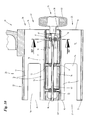
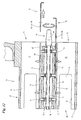
- eine Detaildarstellung von zwei aufeinanderfolgenden bzw. benachbarten Formkammern im Schnitt, in vergrößertem Maßstab,
- Fig. 11
- einen Querschnitt XI-XI der
Fig. 10 , - Fig. 12
- eine Darstellung analog
Fig. 10 bei veränderter Darstellung eines Werkzeugs. - Die in den Zeichnungen dargestellten Beispiele befassen sich mit der Handhabung und Behandlung von quaderförmigen Packungen 10. Konkret handelt es sich um (Zigaretten-)Packungen 10 des Typs Klappschachtel/Hinge Lid. Diese bestehen aus (dünnem) Karton und weisen Faltlappen auf, die mittels aushärtbarer Verbindungsmittel verbunden sind, insbesondere mit Kaltleim.
- Die Packung 10 besteht üblicherweise aus Schachtelteil 11 und Deckel 12. Diese bilden eine Vorderseite mit Schachtel-Vorderwand 13 und Deckel-Vorderwand 14. Gegenüberliegend befinden sich Schachtel-Rückwand 15 und Deckel-Rückwand 16. Seitlich sind die Packungen 10 durch schmale Seitenwände 17, 18 des Schachtelteils 11 und des Deckels 12 begrenzt. Der Schachtelteil 11 bildet eine Bodenwand 19 und der Deckel 12 eine Stirnwand 20. Durch Klebung miteinander verbundene Faltlappen befinden sich insbesondere im Bereich der Seitenwände 17, 18 (miteinander verbundene Seitenlappen), möglicherweise aber auch im Bereich von Bodenwand 19 und Stirnwand 20. Weiterhin kann ein bei diesem Packungstyp üblicher Kragen innerhalb der Packung durch Leimverbindungen fixiert sein.
- Die so oder in anderer Weise ausgebildeten Packungen 10 werden in einer Verpackungsmaschine bekannter Bauart fertiggestellt und mit noch nicht fixierten bzw. noch nicht (vollständig) ausgehärteten Leimverbindungen einer Form- und Trockenstation 21 zugeführt. In dieser werden die Packungen 10 unter Aufrechterhaltung bzw. Schaffung einer korrekten Packungsform bis zum Abbinden der Leimbereiche in formgebenden Halterungen, vorliegend in Formkammern bzw. Formkanälen 22, für eine ausreichende Verweildauer aufgenommen. Nach Stabilisierung werden die Packungen 10 an einen Abförderer 23 übergeben und abtransportiert.
- Eine Mehrzahl von Formkanälen 22 ist in paralleler Ausrichtung an einem Endlosförderer angeordnet, bei dem vorliegenden Ausführungsbeispiel als Kanalkranz an einem Trockenrevolver bzw. Trockenrad 24. Dieses ist zur Erhöhung der Leistungsfähigkeit bzw. für eine zweibahnige Betriebsweise der Anlage mit zwei Kanalkränzen 25, 26 versehen, je mit einer größeren Anzahl von Formkanälen 22. Die Kanalkränze 25, 26 sind konzentrisch zueinander angeordnet, jeweils mit radialer Ausrichtung der benachbarten Formkanäle 22, die demnach paarweise bereitgestellt werden. Das so ausgebildete Trockenrad 24 ist (taktweise) drehend angetrieben, insbesondere derart, dass der Bewegungstakt den Abmessungen der Formkanäle 22 entspricht, sodass diese aufeinanderfolgend unterschiedlichen Stationen zugeführt werden. Die achsparallel angeordneten Formkanäle 22 sind an beiden Enden offen.
- Die weitgehend, aber noch nicht komplett fertiggestellten Packungen 10 werden entlang zweier Packungsbahnen 27, 28 paarweise der Form- und Trockenstation 21 zugeführt. In einem letzten Faltschritt werden außenliegende Seitenlappen zur Bildung der Seitenwände 17, 18 mit Leim versehen, vorliegend mit Hilfe von Leimrädern 29 im Bereich einer Beleimungsstation 30. Danach werden die Faltlappen unter Bildung der Seitenwände 17, 18 gegeneinander gefaltet. Die nun fertiggestellten Packungen 10 werden an das Trockenrad 24 übergeben.
- Die Packungen 10 werden auf der Packungsbahn 27, 28 durch ein Übergabeorgan erfasst und in eine Position zur Einführung bzw. zum Einschub in einen zugeordneten Formkanal 22 bereitgehalten. Das Übergabeorgan ist vorliegend ein Übergaberevolver 31, der in einer parallelen (aufrechten) Ebene zum Trockenrad 24 in unmittelbarer Nachbarschaft zu diesem (taktweise) drehend gelagert ist.
- Der Übergaberevolver 31 ist vorzugsweise entsprechend Darstellung und Beschreibung in
EP 0 317 805 A1 ausgebildet, also mit einer polygonartigen Kontur und jeweils Taschen 32 für je eine Packung 10. Wegen der zweibahnigen Betriebsweise ist der Übergaberevolver 31 mit zwei nebeneinanderliegenden Taschen 32 versehen, die hinsichtlich der Relativstellung einerseits auf die Packungsbahnen 27, 28 und andererseits auf die Stellung der Formkanäle 22 ausgerichtet sind. Der Übergaberevolver 31 ist oberhalb der Packungsbahnen 27, 28 positioniert, derart, dass jeweils zwei Packungen 10 auf den Packungsbahnen 27, 28 erfasst und durch entsprechende Drehbewegung in eine Übergabestation 33 gefördert werden, in der die (zwei) Packungen 10 auf zugeordnete Formkanäle 22 der beiden Kanalkränze 25, 26 ausgerichtet sind (Fig. 4 ). Zwei in radialer Richtung benachbarte Formkanäle 22 werden demnach in der Übergabestation 33 mit Packungen 10 beschickt. - Die behandelten, insbesondere hinsichtlich der Leimverbindungen fertiggestellten Packungen 10 werden an einer Ausschubstation 34 aus dem zu entleerenden Formkanal 22 bzw. aus den zwei gleichzeitig beaufschlagten Formkanälen 22 entnommen und an den Abförderer 23 übergeben. Die Ausschubstation 34 befindet sich vorzugsweise in einer horizontalen Mittelebene des Trockenrads 24. Die Übergabestation 33 ist in Drehrichtung nachfolgend, also bei einer in
Fig. 4 gezeigten Drehung des Trockenrads 24 entgegen dem Uhrzeigersinn unterhalb der Ausschubstation 34 positioniert. In der Abfolge werden demnach zunächst die (fertigen) Packungen 10 aus dem Formkanal 22 herausgefördert und danach entsprechend neue, zu behandelnde Packungen 10 in die Formkanäle 22 eingeführt. - Die Packungen 10 werden vorliegend mittels mechanischer Organe in die Formkanäle 22 eingeführt und ebenfalls mit mechanischen Förderorganen aus diesen abgefördert. Im Bereich der Übergabestation 33 werden Packungen 10 aus den Taschen 32 des Übergaberevolvers 31 abgefördert und in einem gemeinsamen Fördertakt an die unmittelbar benachbarten Formkanäle 22 übergeben.
- Die Transportmittel für die taktweise bewegbaren Packungen 10 sind als Stößel 35, 36 bzw. als Schieber 37 ausgebildet. Die Packungen werden durch den Übergaberevolver 31 in der Übergabestation 33 so präsentiert, dass ein erster Stößel 35 die (zwei nebeneinander liegenden) Packungen 10 an einer freien Packungsseite, vorliegend an der Bodenwand 19 erfassen. Durch entsprechende Querbewegung (Pfeil in
Fig. 9 ) wird die betreffende Packung 10 aus der Tasche 32 aus- und über eine Eintrittsöffnung 38 in den Formkanal 22 eingeschoben. Entsprechend dem besonderen Handhabungsverfahren wird die Packung 10 durch dieses erste Förderorgan - Stößel 35 - in eine erste, eintrittsseitige Stellung innerhalb des Formkanals 22 bewegt. In dieser Einschubstellung liegt die Packung 10 mit der freien Seite - Bodenwand 19 - etwa bündig mit der Eintrittsöffnung 38 des Formkanals 22. - Die Handhabung der Packungen 10 im Bereich der Formkanäle 22 ist in besonderer Weise gelöst, derart, dass die Packungen 10 während mehrerer Arbeits- bzw. Fördertakte und entsprechender Anzahl von Drehungen des Trockenrads 24 in den Formkanälen 22 verbleiben. In einem ersten Fördertakt gelangen die Packungen 10 in die Einschubstellung und danach in einem weiteren Fördertakt in die Ausschubstellung. Bei entsprechender Bemessung der Formkanäle 22 ist eine Zwischenstellung der Packungen 10 innerhalb eines Formkanals 22 möglich, sodass sich drei in Längsrichtung aufeinanderfolgende Packungen 10 in einem Formkanal 22 befinden. Die Packung 10 an der Austrittsseite des Formkanals 22 ist vorzugsweise bündig mit einer Austrittsöffnung 33. Die Packungen 10 werden (zwei) aufeinanderfolgenden Fördertakten ohne wechselseitige Druckübertragung, also ohne druckübertragende Anlage der Wandungen 19, 20 aneinander, transportiert. Bei dem vorliegenden Ausführungsbeispiel ist zwischen den aufeinanderfolgenden Packungen 10 ein Abstand 40 gebildet.
- Bei dem ersten Fördertakt werden die Packungen 10 von einem ersten Stößel 35 aus den Taschen 32 des Übergaberevolvers 31 aus- und in den benachbarten Formkanal 22 eingeschoben. Der Bewegungstakt des Stößels 35 ist so bemessen, dass die Packungen 10 die beschriebene eintrittsseitige erste Position einnehmen (
Fig. 6 ,Fig. 8 ). Ein weiteres Förderorgan, Stößel 36, fördert in einem nachfolgenden Arbeitsschritt die Packung 10 aus der eingangsseitigen Position in die austrittsseitige, zweite Stellung, und zwar ebenfalls durch einen entsprechend begrenzten Fördertakt der hin- und herbewegbaren Stößel 36. - Die an der Eintrittsseite der Formkanäle 22 wirksamen Förderorgane - Stößel 35, 36 - sind so ausgebildet, dass die beiden in einer Radialebene nebeneinander liegenden Formkanäle 22 der Kanalkränze 25, 26gleichzeitig beschickt werden. Des Weiteren wird zeitgleich durch den Stößel 36 der nachfolgende Fördertakt für die Packungen 10 - Verschiebung innerhalb der Formkanäle 22 - ausgeführt. Zu diesem Zweck ist eine Schubeinheit 41 vorgesehen mit einem neben der Ebene des Trockenrads 24 angeordneten, in achsparalleler Richtung bewegbaren Stößelträger 42. An diesem sind entsprechend dem vorliegend angewendeten Verfahren vier Stößel angebracht, nämlich jeweils zwei Stößel 35, 36 für die zwei gleichzeitig bearbeiteten Formkanäle 22. Der Stößelträger 42 wird von einer ortsfesten Antriebseinheit 43 betätigt.
- Im Bereich der Eintrittsseite bzw. der Eintrittsöffnungen 38 der Formkanäle 22 werden demnach während einer Stillstandsphase des Trockenrads 24 einerseits zwei Packungen 10 aus den Taschen 32 aus- und über die Eintrittsöffnung 38 in den zugeordneten Formkanal 22 eingeschoben, und zwar bis zur Einschubstellung (Packung 10 im wesentlichen bündig mit der Eintrittsöffnung 38). Des Weiteren werden (in anderen, benachbarten Formkanälen 22) ebenfalls zwei Packungen 10 aus der Eingangsstellung innerhalb des Formkanals 22 in eine Austrittsstellung verschoben, vorliegend in eine Stellung bündig mit der Austrittsöffnung 39. Zwischen den Transporttakten der Packungen 10 in die Formkanäle 22, innerhalb derselben und für den Ausschub aus den Formkanälen 22 liegt vorzugsweise mindestens eine (Teil-)Drehung des Trockenrads 24.
- Eine Besonderheit ist der Transport der Packungen 10 beim Verlassen eines Formkanals 22 (
Fig. 7 ). Die Packungen 10 werden jeweils von einem Abholförderer erfasst und aus dem Formkanal 22 herausgefördert. Der Abholförderer befindet sich im Bereich der Ausschubstation 34, also in Bewegungsrichtung des Trockenrads 24 vor der Übergabestation 33. - Der Abholförderer ist ein (im wesentlichen) hin- oder herbewegbares Förderorgan mit einem Mitnehmer 44 zum Erfassen der Packung 10 an einer Packungsfläche, vorliegend an der (innenliegenden, quergerichteten) Bodenwand 19. Der Mitnehmer 44 ist mit einer Betätigungseinheit 45 verbunden, und zwar über eine (Zug-)Stange 46. Die Stange 46 wird zunächst in die Abholposition bewegt, in der der Mitnehmer 44 in den Abstand 40 zwischen den benachbarten Packungen 10 eintritt und damit an der quergerichteten Packungswand anliegt (obere Position in
Fig. 7 ). Danach wird die Betätigungseinheit 45 entsprechend den Richtungspfeilen bewegt und damit die Packung 10 aus den beiden Formkanälen 22 herausgezogen. Zur Sicherung der Stellung der Packung 10 bei der Ausschubbewegung ist gegenüberliegend zum Mitnehmer 22 ein Anschlag 47 an der Betätigungseinheit 45 angebracht, der die Packung 10 im Bereich der Stirnwand 20 sichert. - Der Bewegungsablauf des Abholförderers 44, 45, 46 ist in
Fig. 9 schematisch dargestellt. Die Bewegungsbahn ist durch Pfeil 48 (Fig. 9 ) wiedergegeben. Die Fördereinheit wird aus einer Ausgangsstellung außerhalb des Trockenrands 24 in die Übernahme- bzw. Förderstellung bewegt (Fig. 7 , oben). Dabei tritt der Mitnehmer 44 von Außen in den zu entleerenden Förderkanal 22 ein, und zwar in die Lücke bzw. den Abstand 40. Danach wird durch lineare Bewegung die Packung 10 aus dem Formkanal 22 herausgezogen und auf einer plattenförmigen Unterlage 49 zur Mitnahme durch den Abförderer 23 abgelegt. Der Förderer 44, 45, 46 wird abgesenkt, also aus dem Förderbereich herausbewegt und sodann in die Abförderstellung für den nachfolgenden Formkanal 22 geführt. Auch dieser Fördertakt wird durch entsprechende Ausbildung des Förderers 44, 45, 46 im Bezug auf die zwei benachbarten Formkanäle 22 der Kanalkränze 25, 26 zeitgleich durchgeführt. - Die Formkanäle 22 sind als im Querschnitt rechteckige Schächte ausgebildet, in Form und Abmessung entsprechend dem Querschnitt einer Packung 10. Diese wird im Bereich der Vorderseite 13, 14 durch eine Oberwand 50 und gegenüberliegend durch eine Unterwand 51 begrenzt. Letztere liegt an Schachtel- und Deckel-Rückwand 15, 16 an. Im Bereich der schmalen Seitenwände 17, 18 sind Kanalseitenwände 52, 53 gebildet. Die in Radialrichtung nebeneinanderliegenden Formkanäle 22 der Kanalkränze 25, 26 sind vorzugsweise übereinstimmend ausgebildet.
- Eine Besonderheit besteht in der Anordnung von Ausnehmungen 54 im Bereich der Austrittsseite bzw. Austrittsöffnung 39 der Formkanäle 22. Diese Ausnehmungen 54 sind in mindestens einer der großen Wandungen 50, 51, vorzugsweise im Bereich von Oberwand 50 und Unterwand 51 angeordnet. Die Ausnehmungen 54 sind zur Austrittsöffnung 39 hin offen und erstrecken sich über die Länge einer Packung 10 und bis in den Bereich des Abstands 40. Die Ausnehmung 54 ermöglicht die Zuführung und den Eingriff es Förderers bzw. des Schiebers 37 zur Abholung der Packung 10. Die Stange 46 mit dem Mitnehmer 47 tritt über einen benachbarten, in diesem Bereich entleerten Formkanal 22 in die Entnahmeposition ein, wobei die Stange 46 im Bereich der Ausnehmung 54 einer Wandung 50, 51 liegt und der Mitnehmer über diese Ausnehmung 54 in die Mitnehmerstellung im Bereich des Abstands 40 eintritt.
- Die Ausnehmung 54 ist vorzugsweise mittig im Bereich der Kanalseitenwände 52, 53 angeordnet und zum Ende hin offen. Seitlich, also zu beiden Seiten der Ausnehmung 54, sind Schenkel 55 gebildet für die Anlage der Packung 10 in der austrittsseitigen Stellung. Der Schieber 37 bzw. die Zug-Stange 46 durch achsparallele Bewegung im benachbarten Formkanal 22 und durch abschließende Querbewegung in die Abschubstellung, wobei durch die Querbewegung der Mitnehmer 44 Anlage an der freien Packungswandung - Bodenwand 19 - erhält.
- Die Bewegungen der Packungen 10 im Bereich des Trockenrades 24 sind aufeinander abgestimmt. Vorliegend besteht ein erster Fördertakt aus der Einschubbewegung in einen Formkanal 22. Nachfolgend - nach mindestens einer (Teil-)Drehung des Trockenrades 24 - wird ein Fördertakt innerhalb des Formkanals 22 durchgeführt und die Packung 10 an der Austrittsseite positioniert. Danach wird die Packung 10 aus dem Formkanal 22 herausgefördert. Der Ablauf der Bewegungen ist so gesteuert, dass - der Bewegung des Trockenrades 24 folgend - zuerst die austrittsseitig positionierte Packung 10 aus dem Formkanal 22 herausbewegt und damit diese Position freigemacht wird. Danach - in Bewegungsrichtung - wird die Packung 10 aus der Eintrittsposition innerhalb des Formkanals 22 in die Austrittsposition bewegt. Dadurch wird diese Position frei. Anschließend erfolgt der Einschub einer Packung 10 in die eintrittsseitige Position. Die beiden Letztgenannten Förderbewegungen innerhalb des Formkanals 22 werden durch die entsprechend ausgebildete Schubeinheit 41 zeitgleich durchgeführt.
- Eine Besonderheit sind die Maßnahmen zur Sicherstellung einer gradlinigen, hin- und hergehenden Bewegung der Stößel 35, 36, insbesondere als Schubeinheit 41. Zu dieser gehört ein Ausgleichsgetriebe 56, außerhalb des Bewegungsbereichs des Trockenrades 24, mit dem Ziel, eine exakte hin- hergehende Linearbewegung der Stößel 35, 36 zu gewährleisten. Das Ausgleichsgetriebe besteht aus einem achsparallel gelagerten Tragteil 57, welches vorliegend am Außenumfang des Trockenrades 24 mit geringem Abstand von diesem positioniert ist. Mit dem Tragteil 57 sind die Stößel 35,36 verbunden, und zwar über (horizontale und vertikale) Tragstangen 58, 59. Das Tragteil 57 wird durch ein Antriebsorgan von einem nichtgezeigtem Antrieb bewegt, vorliegend durch eine Zug- und Schubstange 60.
- Das Tragteil 57 ist in besonderer Weise gelagert, um die exakte Linearbewegung sicherzustellen. Es handelt sich dabei (ausschließlich) um Hebel, vorliegend um zwei im Abstand voneinander angeordnete Hebeleinheiten 61, 62. Jede Einheit besteht aus einem gelenkig bzw. schwenkbar mit dem Tragteil 57 verbundenen Haupthebel 63 und zwei Ausgleichshebeln 64, 65. Diese sind (annähernd in Parallelstellung zueinander) ortsfest, schwenkbar gelagert, nämlich im Bereich von feststehenden Drehlagern 66 und über Gelenke 67 im Abstand voneinander mit einem freien, vom Tragteil 57 entfernt liegenden Gelenk 67 verbunden. Durch Betätigen des Ausgleichsgetriebes 56, nämlich durch Kraftübertragung der Zug- und Schubstange 60, werden demnach die Stößel 35 in der beschriebenen Weise hin- und hergehend bewegt.
- Eine weitere Besonderheit ist die Schaffung von Voraussetzungen für eine erleichterte Wartung bzw. Anpassung der Anlage an unterschiedliche Packungen. Zu diesem Zweck ist die Übertragungseinheit für die Packungen 10 von der Packungsbahn 27, 28 an das Trockenrad 24 - Übergaberevolver 31 - verschiebbar an einem Träger angeordnet, und zwar derart, dass der Übergaberevolver 31 durch einfache Betätigung aus der Arbeitsstellung (z. B.
Fig. 3 ,Fig. 4 ) in eine freie Bearbeitungsposition bewegbar ist (Fig. 5 ). Der Übergaberevolver 31 ist zu diesem Zweck an einem Schwenkarm 68 gelagert, der auf einem Maschinenfundament mit einem Schwenklager 69 gelagert ist. Der Schwenkarm 68 ist (mit Übergaberevolver 31) um nahezu 180° schwenkbar aus der Arbeitsstellung in die Bearbeitungsposition (Fig. 5 ). Hier kann durch einfache Maßnahme der Übergaberevolver 31 vom Schwenkarm 68 abgenommen und beispielsweise gegen einen anderen Übergaberevolver 31 (für ein anderes Packungsformat) ausgetauscht werden. - Eine weitere Besonderheit besteht darin, dass die Formkanäle 22 hinsichtlich der Querschnittsform und/oder hinsichtlich der (Querschnitts-)Abmessungen verstellbar sind. Bei dem vorliegenden Beispiel ist eine Kanalfläche, hier eine schmale Kanalseitenwand 52, 53 mit einer Stellmechanik versehen, die eine Veränderung der Querabmessung des Formkanals 22 (wirksamer Abstand zwischen den Kanalseitenwände 52, 53) ermöglicht.
- Im Bereich der einen und/oder anderen Seitenwand 52, 53 befindet sich ein verstellbares Organ, vorliegend ein Drucksteg 70, der sich vorzugsweise über die volle Länge des Formkanals 22 bzw. der zugeordneten Seitenwand 52, 53 erstreckt. Der Drucksteg 70 ist als Wandung ausgebildet und bildet mit der freien Seite die (seitliche) Begrenzung des Formkanals 22. Der Drucksteg 70 liegt demnach an der zugekehrten Seitenwand 17, 18 der Packung 10 an. Bei dem gezeigten Ausführungsbeispiel sind die Druckstege 70 der benachbarten Formkanäle 22 der Kanalkränze 25, 26 im Bereich der einander zugekehrten Kanalseitenwände 52, 53 angeordnet.
- Die Druckstege 70 sind außerhalb des Formkanals 22 (beweglich) abgestützt. Zu diesem Zweck ist jeder Drucksteg 70 mit über die Länge verteilten (drei) Tragbolzen 71 versehen. Diese sind an der vom Innenbereich des Formkanals 22 abgekehrten, äußeren Seite angeordnet und treten durch Bohrungen 72 in der Tragkonstruktion des Trockenrads 24 hindurch, nämlich durch einander zugekehrte Zwischenwände 73, 74 der benachbarten Formkanäle 22 bzw. der Kanalkränze 25, 26. Zwischen diesen Zwischenwänden 73, 74 befindet sich ein Zwischenraum bzw. eine Kammer 75, in die die Tragbolzen 71 eintreten. Auf jedem Tragbolzen 71 befindet sich eine Stützfeder 76, die an der Zwischenwand 73, 74 einerseits und an einem Bolzenkopf 77 andererseits abgestützt ist. Die Stützfedern 76 ermöglichen eine Querverschiebung der Druckstege 70 gegen Federbelastung
- Die Relativstellung der Druckstege 70 innerhalb des jeweiligen Formkanals 22 ist veränderbar, und zwar insbesondere durch Parallelverschiebung. Soweit durch die Stellung der Druckstege 70 gegenüber den Zwischenwänden 73, 74 ein spaltförmiger Zwischenraum geschaffen ist, wird in diesen ein geeignetes Distanzstück eingeführt, welches die Relativstellung des Druckstegs 70 aufgrund der Wirkung der Stützfedern 76 bestimmt. Bei dem gezeigten Ausführungsbeispiel handelt es sich um ein langgestrecktes blechartiges Distanzstück 78, welches über eine freie Seite des Formkanals 22, vorliegend über die Eintrittsseite 38, in den Spalt zwischen Drucksteg 70 und Zwischenwand 73, 74 eingeschoben wird. Je nach Stärke bzw. Dicke des Distanzstücks 78 wird die Relativstellung des Druckstegs 70 bestimmt und damit die (Quer-) Abmessung des Formkanals 22.
- Zur Veränderung der Stellung der Druckstege 70 ist ein besonderes Werkzeug 79 vorgesehen. Dieses besteht aus einer Drehstange 80 mit besonderem Querschnitt (insbesondere oval). An einem Ende der Drehstange 80 ist ein Handgriff 81 angebracht. Das Werkzeug 79 bzw. die Drehstange 80 wird über entsprechende Öffnungen bzw. Bohrungen 86, 87 in den Zwischenwänden 73, 74 in die Kammer 75 eingeführt, derart, dass Endbereiche der Drehstange 80 in Öffnungen bzw. Bohrungen 86, 87 drehbar gelagert sind. Die Drehstange 80 befindet sich zwischen den einander zugekehrten Enden (Bolzenkopf 77) der Tragbolzen 71 benachbarter Formkanäle 22. Diese liegen mit abgerundeten Kopfflächen an dem Werkzeug bzw. an der Drehstange 80 an, so dass durch Betätigung des Werkzeugs 79 die Tragbolzen 71 (gemeinsam) beaufschlagt werden. Das Werkzeug 79 bzw. dessen Drehstange 80 ist vorzugsweise im Bereich der Kammer 75 gelagert, nämlich im Bereich von quergerichteten Schenkeln der Zwischenwände 73, 74, die jeweils die Bohrungen 86, 87, als Drehlager für die Drehstange 80 bilden.
- Bei der Einführung des Werkzeugs 79 ist die Drehstange 80 so positioniert, dass die Tragbolzen 71 bzw. die Bolzenköpfe 77 an Bereichen mit geringem Querschnitt anliegen (
Fig. 11 , oben). Die Tragbolzen 71 der benachbarten Formkanäle 22 befinden sich in Abstützung an dem Distanzstück 78. Durch Stellungsänderung der Drehstange 80 wird der größere bzw. volle Querschnitt der Drehstange 80 wirksam. Die Bolzen 71 werden auseinander bewegt - gegen den Druck der Stützfedern 76 - und dadurch die Druckstege 70 nach innen in den Formkanal 22 bewegt (Fig. 11 , Mitte). Es kann nun ein anderes, z. B. größeres Distanzstück 78 in Position gebracht werden (Fig. 11 , unten). Durch Rückdrehung der Drehstange 80 kommen die Tragbolzen 71 frei, so dass die Druckstege 70 bis zur Anlage an dem (neuen) Distanzstück 78 verschoben werden. - Die Distanzstücke 78 sind in besonderer Weise ausgebildet, nämlich als langgestreckte Bleche mit einem Längsschlitz 82. Das dadurch gabelförmige Distanzstück 78 kann in Längsrichtung in den Formkanal 22 eingeschoben werden, so dass Distanzstege 83, 84 zu beiden Seiten der Tragbolzen 71 im Wesentlichen über die gesamte Länge der Druckstege 70 verlaufen. An den Enden der Distanzstücke 78 sind durch winkelförmige Ausbildung Betätigungsgriffe angeordnet.
- Die vorstehend ausgebildete Mechanik zur Veränderung der Querabmessungen des Formkanals 22 können auch zusätzlich oder alternativ für andere Wandungsbereiche eingesetzt werden.
- Die mit der so ausgebildeten Vorrichtung fertiggestellten Packungen 10 werden durch den Abförderer 23 einem abschließenden Prüfaggregat 85 zugeführt zur Kontrolle der exakten äußeren Struktur.
Bezugszeichenliste: 10 Packung 46 (Zug-)Stange 83 Distanzsteg 11 Schachtelteil 47 Anschlag 84 Distanzsteg 12 Deckel 48 Pfeil 85 Prüfungsaggregat 13 Schachtel-Vorderwand 49 Unterlage 86 Bohrung 50 Oberwand 87 Bohrung 14 Deckel-Vorderwand 51 Unterwand 15 Schachtel-Rückwand 52 Kanalseitenwand 16 Deckel-Rückwand 53 Kanalseitenwand 17 Seitenwand 54 Ausnehmung 18 Seitenwand 55 Schenkel 19 Bodenwand 56 Ausgleichsgetriebe 20 Stirnwand 57 Tragteil 21 Form- und Trockenstation 58 Tragstange 59 Tragstange 22 Formkanal 60 Zug- und Schubstange 23 Abförderer 24 Trockenrad 61 Hebeleinheit 25 Kanalkranz 62 Hebeleinheit 26 Kanalkranz 63 Haupthebel 27 Packungsbahn 64 Ausgleichshebel 28 Packungsbahn 65 Ausgleichshebel 29 Leimrad 66 Drehlager 30 Beleimungsstation 67 Gelenk 31 Übergaberevolver 68 Schwenkarm 32 Tasche 69 Schwenklager 33 Übergabestation 70 Drucksteg 34 Ausschubstation 71 Tragbolzen 35 Stößel 72 Bohrung 36 Stößel 73 Zwischenwand 37 Schieber 74 Zwischenwand 38 Eintrittsöffnung 75 Kammer 39 Austrittsöffnung 76 Stützfeder 40 Abstand 77 Bolzenkopf 41 Schubeinheit 78 Distanzstück 42 Stößelträger 79 Werkzeug 43 Antriebseinheit 80 Drehstange 44 Mitnehmer 81 Handgriff 45 Betätigungseinheit 82 Längsschlitz
Claims (15)
- Verfahren zur Formgebung bzw. Formstabilisierung von Packungen (10) mit durch Leim verbundenen Faltlappen, insbesondere von quaderförmigen Zigarettenpackungen des Typs Klappschachtel aus (dünnem) Karton, wobei mehrere aufeinanderfolgende Packungen (10) durch einen formgebenden Kanal - Formkanal (22) - hindurch transportiert werden, der die Packungen (10) an mehreren Seiten umgibt und mit formgebenden Kanalwandungen an den Packungen (10) anliegt, vorzugsweise an Vorderwand (13, 14), Rückwand (15, 16) und schmalen, langgestreckten Seitenwänden (17, 18), dadurch gekennzeichnet, dass die Packungen (10) drucklos, also ohne wechselseitige Abstützung, insbesondere mit Abstand (40) voneinander, durch den Formkanal (22) (taktweise) hindurchtransportiert werden, wobei vorzugsweise die Packungen (10) durch Einschieben über eine Eintrittsseite bzw. Eintrittsöffnung (38) in den Formkanal (22) eingeführt und auf der gegenüberliegenden Seite durch gesonderten Antrieb aus dem Formkanal (22) über eine Austrittsöffnung (39) herausbewegt werden, vorzugsweise nach mehreren (taktweisen) Drehungen eines endlosen Trockenförderers, insbesondere eines Trockenrades (24), mit einer Vielzahl von längs des Umfangs angeordneten Formkanälen (22).
- Verfahren nach Anspruch 1, dadurch gekennzeichnet, dass die (quaderförmigen) Packungen (10) durch mindestens ein Schuborgan - Stößel (35, 36) - durch Übertragung von Druck auf eine quergerichtete, rückseitige Packungswandung - vorzugsweise Bodenwand (19) oder Stirnwand (20) einer Klappschachtel - in den Formkanal (22) eingeschoben und nach Beendigung des Formgebungsprozesses an der gegenüberliegenden Seite durch ein gesondertes Förderorgan - Antriebseinheit (43) mit Mitnehmer (44) zum Erfassen der Packung (10) ebenfalls an der rückwärtigen Packungsseite - aus dem Formkanal (22) herausgefördert wird, wobei mehrere Packungen (10) innerhalb eines Formkanals (22) einen Abstand (40) voneinander aufweisen, wobei vorzugsweise mindestens zwei Fördertakte der Packungen (10) innerhalb eines Formkanals (22) über die Eintrittsöffnung (38) bewirkt werden und mindestens ein weiterer Fördertakt, insbesondere ein Ausschubtakt der Packung (10) aus dem Formkanal (22), über die Austrittsöffnung (39) ausgeführt wird.
- Verfahren nach Anspruch 1 oder 2, dadurch gekennzeichnet, dass Fördertakte der Packungen (10) in die Formkanäle (22), in diesen sowie aus den Formkanälen (22) heraus in aufeinanderfolgenden Stationen im Bewegungsablauf des Trockenförderers - Trockenrad (24) - erfolgen, insbesondere derart, dass in einer ersten Station - Ausschubstation (34) - Packungen (10) über die Austrittsöffnung (39) aus dem Formkanal (22) herausgefördert, in einer nachfolgenden (ersten) Übergabestation (33) Packungen (10) aus einer Eintrittsstellung in eine weitere, nachfolgende Stellung innerhalb des Formkanals (22) bewegbar und das schließlich in einer weiteren Stellung der Übergabestation (33) Packungen (10) in den Formkanal (22) eingeschoben werden, vorzugsweise durch Übernahme von einem Übergaberevolver (31), wobei vorzugsweise die Einschubbewegung von Packungen (10) in die Formkanäle (22) im Bereich der Übergabestation (33) und ein nachfolgender Fördertakt, insbesondere von der Eintrittsstellung in die Austrittsstellung, durch gemeinsamen Fördertakt, vorzugsweise durch eine Schubeinheit (41), ausgeführt werden.
- Verfahren nach Anspruch 1 oder einem der weiteren Ansprüche, dadurch gekennzeichnet, dass die austrittsseitig in einem Formkanal (22) positionierten Packungen (10) über einen Förderer ausschiebbar sind - Betätigungseinheit (45) -, der über einen benachbarten, bereits (teilweise) entleerten Formkanal (22) in die Förderstellung zum Abtransport der Packung (10) gebracht wird.
- Verfahren nach Anspruch 1 oder einem der weiteren Ansprüche, dadurch gekennzeichnet, dass die Formkanäle (22) hinsichtlich (Querschnitts-)Form und/oder Abmessung, insbesondere hinsichtlich der Breite, verstellbar sind, vorzugsweise durch Querverschieben einer Kanalseitenwand (52, 53) bzw. eines Teils derselben.
- Vorrichtung zur Formgebung bzw. Formstabilisierung von Packungen (10), die durch Leim miteinander verbundene Faltlappen aufweisen, insbesondere quaderförmige Zigarettenpackungen des Typs Klappschachtel aus (dünnem) Karton, wobei mehrere formgebende Kanäle bzw. Taschen - Formkanal (22) - an einem Endlosförderer - Trockenrad (24) - angeordnet und die Packungen (10) in Längsrichtung durch die Formkanäle (22) taktweise hindurchförderbar sind bis zum Aushärten der Leimverbindungen, gekennzeichnet durch folgende Merkmale:a) im Bereich einer Übergabestation (33) sind vorzugsweise zwei Packungen (10) durch eine Schubeinheit (41) in (zwei) Formkanäle (22) einschiebbar,b) die Packungen (10) sind innerhalb der Formkanäle (22) um mindestens einen weiteren Fördertakt bewegbar, vorzugsweise durch die entsprechend ausgebildete Schubeinheit (41),c) die Packungen (10) werden im Bereich einer Ausschubstation (34) durch vorzugsweise gesonderte Förderorgane - Betätigungseinheit (45) - über eine Austrittsöffnung (39) aus den Formkanälen (22) herausgefördert,d) die Organe für den (taktweisen) Förderantrieb der Packungen (10) sind so ausgebildet bzw. bemessen, dass mehrere, insbesondere zwei innerhalb eines Formkanals (22) nebeneinanderliegende Packungen (10) druckfrei, insbesondere mit Abstand voneinander transportierbar sind.
- Vorrichtung nach Anspruch 6, dadurch gekennzeichnet, dass das Trockenrad (24) mehrere, insbesondere zwei konzentrische Kanalkränze (25, 26) aufweist, je mit derselben Anzahl von achsparallelen Formkanälen (22), wobei die benachbarten Formkanäle (22) der Kanalkränze (25, 26) in Radialrichtung aufeinander ausgerichtet sind und durch gemeinsame Förder- bzw. Schuborgane im Bereich der Übergabestation (33) beschickt und im Bereich der Ausschubstation (34) entleert werden.
- Vorrichtung nach Anspruch 6 oder 7, dadurch gekennzeichnet, dass in einer Förderstation für die Packungen (10), insbesondere in der gemeinsamen Übergabestation (33) durch eine gemeinsame Schubeinheit (41) vorzugsweise in einenm Fördertakt (zwei) Packungen (10) in nebeneinanderliegende Formkanäle (22) einschiebbar und (zwei) weitere Packungen (10) innerhalb von benachbarten (anderen) Formkanälen (22) um einen Fördertakt weiterbewegbar sind, wobei die Schubeinheit (41) vorzugsweise jeweils einer Packung (10) zugeordnete Stößel (35, 36) in unterschiedlicher Relativstellung aufweist für die Durchführung der Fördertakte, wobei weiterhin vorzugsweise eine Übergabevorrichtung für Packungen (10), insbesondere ein Übergaberevolver (31) mit vorzugsweise zwei nebeneinanderliegenden Taschen (32) in einer Ebene unmittelbar benachbart zum Trockenrad (24) gelagert ist, derart, dass aufgrund entsprechender Relativstellung der Taschen (32) mit einem ersten Fördertakt (zwei) Packungen (10) aus den Taschen (32) ausschiebbar und in (zwei) unmittelbar benachbarte Formkanäle (22) einschiebbar und in einer eintrittsseitigen ersten Position ablegbar sind.
- Vorrichtung nach Anspruch 6 oder einem der weiteren Ansprüche, dadurch gekennzeichnet, dass dem Trockenrad (24) mit vorzugsweise zwei Kanalkränzen (25, 26) Übergabestation (33) und Ausschubstation (34) an unterschiedlichen Positionen, bezogen auf die Drehbewegung des Trockenrads (24), zugeordnet sind, nämlich derart, dass in Förderrichtung der Formkanäle (22) zuerst im Bereich der Ausschubstation (34) einer Austrittsöffnung (39) zugeordnete Packungen (10) aus den (zwei) Formkanälen (22) herausgefördert werden und in Bewegungsrichtung der Formkanäle (22) nachfolgend in der Übergabestation (33) in einem ersten Fördertakt Packungen (10) aus einer Einschubstellung in die Ausschubstellung und in einer nachfolgenden Position Packungen (10) in die Formkanäle (22) einschiebbar sind.
- Vorrichtung nach Anspruch 6 oder einem der weiteren Ansprüche, dadurch gekennzeichnet, dass die im Querschnitt geschlossenen Formkanäle (22) mit Oberwand (50), Unterwand (51) und Kanalseitenwänden (52, 53) im Bereich der Austrittsöffnung (39) mindestens eine Ausnehmung (54) in mindestens einer Wandung des Formkanals (22) aufweisen, insbesondere je im Bereich der Oberwand (50) und Unterwand (51), wobei sich die Ausnehmungen (54) über einen Bereich erstrecken, der etwas länger ist als die Längsabmessung einer Packung (10), derart dass im Bereich einer quergerichteten Wandung der Packung (10), insbesondere im Bereich einer Bodenwand (19), ein freier Bereich der Ausnehmung (54) gebildet ist, in die die Betätigungseinheit (45) zum Abtransport der Packungen (10) eintritt, vorzugsweise mit einem Mitnehmer (44), wobei vorzugsweise der Austrittsöffnung (39) zugekehrte Packungen (10) durch die an der Austrittsseite im Bereich der Ausschubstation (34) angebrachte ortsfeste Betätigungseinheit (45) aus den Formkanälen (22) herausförderbar sind, insbesondere mit einer Zugstange (46) und einem Mitnehmer (44), der für den Abtransport die Packung (10) an der innenseitigen Bodenwand (19) erfasst, wobei das Betätigungsorgan - Stange (46) mit Mitnehmer (44) - über einen in Bewegungsrichtung des Trockenrades (24) der Ausschubstation (34) vorgeordneten im austrittsseitigen Bereich entleerten Formkanal (22) in die Mitnahmeposition für die Packung (10) bewegbar ist.
- Vorrichtung nach Anspruch 6 oder einem der weiteren Ansprüche, dadurch gekennzeichnet, dass das Organ zur Übergabe der Packungen (10) von einer Packungsbahn (27, 28) an das Trockenrad (24), insbesondere der Übergaberevolver (31), an einer verstellbaren Halterung oder verstellbar an der Halterung angebracht ist, insbesondere an einem Schwenkarm (68), durch den der Übergaberevolver (31) in eine vom Trockenrad (24) entfernte Handhabungsstellung schwenkbar ist.
- Packung nach Anspruch 6 oder einem der weiteren Ansprüche, dadurch gekennzeichnet, dass Förderorgane für die Packungen (10), insbesondere die Schubeinheit (41) mit den Stößeln (35, 36) an einem Lineargetriebe bzw. an einem Ausgleichsgetriebe (56) gelagert ist, dass aus mindestens einem Tragteil (57) für die Förderorgane (35, 36) und (zwei) Hebelgetrieben bzw. Hebeleinheiten (61, 62) besteht, insbesondere jeweils mit einem schwenkbaren Haupthebel (63) und ortsfesten, ebenfalls schwenkbaren Ausgleichshebeln (64, 65), die mit einem freien Ende des Haupthebels (63) verbunden sind.
- Vorrichtung nach Anspruch 6 oder einem der weiteren Ansprüche, dadurch gekennzeichnet, dass die Formkanäle (22) hinsichtlich der Abmessungen durch verstellbare Begrenzungsorgane veränderbar sind, insbesondere durch mindestens einen Drucksteg (70) in jedem Formkanal (22), wobei vorzugsweise ein langgestreckter, streifenförmiger Drucksteg (70) im Bereich mindestens einer Seitenwand (52, 53) eines Formkanals (22) angeordnet ist und der Drucksteg (70) hinsichtlich der Relativstellung innerhalb des Formkanals (22) verstellbar ist unter Veränderung der entsprechenden Abmessung - Breite - des Formkanals (22).
- Vorrichtung nach Anspruch 12 oder einem der weiteren Ansprüche, dadurch gekennzeichnet, dass die Druckstege (70) mittels Führungsorganen, insbesondere mit Tragbolzen (71), in Seitenwänden der Formkanäle (22) verschiebbar gelagert sind, vorzugsweise in den einander zugekehrten Seitenwänden (52, 53) der in Radialrichtung des Trockenrads (24) benachbarten Formkanäle (22), wobei vorzugsweise die Führungsorgane bzw. Tragbolzen (71) in zwischen dem benachbarten Formkanälen (22) angeordneten Zwischenwänden (73, 74) federelastisch gelagert sind.
- Vorrichtung nach Anspruch 12 oder einem der weiteren Ansprüche, dadurch gekennzeichnet, dass die Druckstege (70) von außerhalb des Trockenrades (24) verstellbar sind, insbesondere durch ein Werkzeug (79), welches mit einem Arbeitsteil, insbesondere einer Drehstange (80), auf die Tragbolzen (71) für die Druckstege (70) der benachbarten Formkanäle (22) einwirkt zur Verstellung derselben, wobei vorzugsweise die Stellung des Druckstegs (70) innerhalb des Formkanals (22) durch Distanzstücke (28) fixiert ist, die vorzugsweise als dünnwandige, langgestreckte Abstandshalter zwischen den Druckstegen (70) einerseits und den Zwischenwänden (73, 74) andererseits positioniert sind und die durch die Wandungsdicke die Relativstellung des Dreckstegs (70) bestimmen.
Applications Claiming Priority (1)
| Application Number | Priority Date | Filing Date | Title |
|---|---|---|---|
| DE102014012968.3A DE102014012968A1 (de) | 2014-09-08 | 2014-09-08 | Verfahren und Vorrichtung zur Formstabilisierung von Packungen |
Publications (2)
| Publication Number | Publication Date |
|---|---|
| EP2993140A1 true EP2993140A1 (de) | 2016-03-09 |
| EP2993140B1 EP2993140B1 (de) | 2018-02-21 |
Family
ID=54011941
Family Applications (1)
| Application Number | Title | Priority Date | Filing Date |
|---|---|---|---|
| EP15002525.2A Active EP2993140B1 (de) | 2014-09-08 | 2015-08-26 | Verfahren und vorrichtung zur form-stabilisierung von packungen |
Country Status (3)
| Country | Link |
|---|---|
| EP (1) | EP2993140B1 (de) |
| CN (1) | CN105398610A (de) |
| DE (1) | DE102014012968A1 (de) |
Cited By (8)
| Publication number | Priority date | Publication date | Assignee | Title |
|---|---|---|---|---|
| CN107187660A (zh) * | 2017-05-16 | 2017-09-22 | 刘晓富 | 一种刹车片制造厂用高效率包装装置 |
| CN109219559A (zh) * | 2016-04-04 | 2019-01-15 | Gima Tt 股份有限责任公司 | 用于吸烟制品有序群组的传送装置、包括上述传送装置的供给和形成吸烟制品有序群组的设备以及方法 |
| CN109353805A (zh) * | 2018-11-29 | 2019-02-19 | 东莞市达孚电子有限公司 | 一种薄膜电容器的移动上料装置 |
| CN110667176A (zh) * | 2019-10-25 | 2020-01-10 | 中科天工(武汉)智能技术有限公司 | 包装盒加工驱动装置及包装盒加工设备 |
| CN112093111A (zh) * | 2020-09-30 | 2020-12-18 | 上海烟草机械有限责任公司 | 烟包装填装置 |
| CN113401439A (zh) * | 2021-07-28 | 2021-09-17 | 广东省韶关烟草机械配件厂有限公司 | 一种烟包双通道透明纸除皱设备 |
| CN114689295A (zh) * | 2022-02-14 | 2022-07-01 | 重庆中烟工业有限责任公司 | 一种硬质烟盒翻盖闭合检测装置及其检测方法 |
| CN117682174A (zh) * | 2023-12-29 | 2024-03-12 | 河北白沙烟草有限责任公司保定卷烟厂 | 一种用于yb45型硬盒包装机的商标纸内舌折叠机构 |
Families Citing this family (7)
| Publication number | Priority date | Publication date | Assignee | Title |
|---|---|---|---|---|
| CN106113578B (zh) * | 2016-06-29 | 2018-08-28 | 德清中盈文具用品有限公司 | 一种防碰撞的包装盒围边定型结构 |
| CN106113579B (zh) * | 2016-06-29 | 2018-02-02 | 德清中盈文具用品有限公司 | 一种包装盒的围边定型结构及定型方法 |
| CN106113588B (zh) * | 2016-06-29 | 2018-02-02 | 德清中盈文具用品有限公司 | 一种心形包装盒的围边定型结构及定型方法 |
| CN110092025B (zh) * | 2019-05-31 | 2024-08-30 | 福建烟草机械有限公司 | 一种细支烟七号轮总成 |
| CN110430743B (zh) * | 2019-08-12 | 2020-10-13 | 深圳鼎典创造体设计有限公司 | 一种轮齿式电子设备外壳自动安装设备 |
| CN114013972B (zh) * | 2021-11-15 | 2023-09-01 | 真味生物(深圳)集团有限公司 | 一种带有限位结构的电子雾化器生产用输送装置 |
| CN120057374B (zh) * | 2025-04-29 | 2025-07-08 | 福建八马茶业有限公司 | 一种茶叶自动包装装置 |
Citations (7)
| Publication number | Priority date | Publication date | Assignee | Title |
|---|---|---|---|---|
| EP0197368A2 (de) * | 1985-04-06 | 1986-10-15 | Focke & Co. (GmbH & Co.) | Verfahren und Vorrichtung zum Verpacken von insbesondere Zigaretten |
| EP0243757A2 (de) * | 1984-01-11 | 1987-11-04 | Focke & Co. (GmbH & Co.) | Verpackungsmaschine für Packungen mit durch Klebung verbundenen Faltlappen |
| EP0317805A1 (de) | 1987-11-21 | 1989-05-31 | Focke & Co. (GmbH & Co.) | Vorrichtung zum Transport von Zigaretten-Packungen im Zusammenhang mit einer Verpackungsmaschine |
| EP0437201A1 (de) | 1990-01-12 | 1991-07-17 | Focke & Co. (GmbH & Co.) | Vorrichtung zur Formstabilisierung quaderförmiger (Zigaretten-)Packungen |
| GB2250257A (en) * | 1990-11-27 | 1992-06-03 | Focke & Co | Apparatus for setting the glue on newly-completed cigarette packs |
| EP0867372A1 (de) * | 1997-03-27 | 1998-09-30 | TOPACK Verpackungstechnik GmbH | Taschenrad zur Aufnahme von Packungen der tabakverarbeitenden Industrie |
| EP0931725A1 (de) * | 1998-01-27 | 1999-07-28 | G.D Societa' Per Azioni | Vorrichtung zum Konditionnieren von Zigarettenpackungen |
Family Cites Families (5)
| Publication number | Priority date | Publication date | Assignee | Title |
|---|---|---|---|---|
| DE3605177A1 (de) * | 1986-02-19 | 1987-08-20 | Focke & Co | Vorrichtung zum lagern von (zigaretten-) packungen |
| DE3701768A1 (de) * | 1987-01-22 | 1988-08-04 | Focke & Co | Verpackungsmaschine mit trockenrevolver |
| DE3736403A1 (de) * | 1987-10-28 | 1989-05-11 | Focke & Co | Vorrichtung zum stabilisieren und trocknen von quaderfoermigen packungen |
| DE102009050035A1 (de) * | 2009-10-20 | 2011-04-21 | Focke & Co.(Gmbh & Co. Kg) | Vorrichtung zum Speichern von (Zigaretten-)Packungen |
| ITBO20130227A1 (it) * | 2013-05-17 | 2014-11-18 | Gd Spa | Unità e metodo di trasferimento di pacchetti per trasferire i pacchetti da due percorsi di ingresso gemelli e separati ad un unico percorso di uscita comune. |
-
2014
- 2014-09-08 DE DE102014012968.3A patent/DE102014012968A1/de not_active Withdrawn
-
2015
- 2015-08-26 EP EP15002525.2A patent/EP2993140B1/de active Active
- 2015-09-08 CN CN201510564912.6A patent/CN105398610A/zh active Pending
Patent Citations (7)
| Publication number | Priority date | Publication date | Assignee | Title |
|---|---|---|---|---|
| EP0243757A2 (de) * | 1984-01-11 | 1987-11-04 | Focke & Co. (GmbH & Co.) | Verpackungsmaschine für Packungen mit durch Klebung verbundenen Faltlappen |
| EP0197368A2 (de) * | 1985-04-06 | 1986-10-15 | Focke & Co. (GmbH & Co.) | Verfahren und Vorrichtung zum Verpacken von insbesondere Zigaretten |
| EP0317805A1 (de) | 1987-11-21 | 1989-05-31 | Focke & Co. (GmbH & Co.) | Vorrichtung zum Transport von Zigaretten-Packungen im Zusammenhang mit einer Verpackungsmaschine |
| EP0437201A1 (de) | 1990-01-12 | 1991-07-17 | Focke & Co. (GmbH & Co.) | Vorrichtung zur Formstabilisierung quaderförmiger (Zigaretten-)Packungen |
| GB2250257A (en) * | 1990-11-27 | 1992-06-03 | Focke & Co | Apparatus for setting the glue on newly-completed cigarette packs |
| EP0867372A1 (de) * | 1997-03-27 | 1998-09-30 | TOPACK Verpackungstechnik GmbH | Taschenrad zur Aufnahme von Packungen der tabakverarbeitenden Industrie |
| EP0931725A1 (de) * | 1998-01-27 | 1999-07-28 | G.D Societa' Per Azioni | Vorrichtung zum Konditionnieren von Zigarettenpackungen |
Cited By (10)
| Publication number | Priority date | Publication date | Assignee | Title |
|---|---|---|---|---|
| CN109219559A (zh) * | 2016-04-04 | 2019-01-15 | Gima Tt 股份有限责任公司 | 用于吸烟制品有序群组的传送装置、包括上述传送装置的供给和形成吸烟制品有序群组的设备以及方法 |
| CN107187660A (zh) * | 2017-05-16 | 2017-09-22 | 刘晓富 | 一种刹车片制造厂用高效率包装装置 |
| CN107187660B (zh) * | 2017-05-16 | 2019-04-23 | 龙口市隆昌汽车配件有限公司 | 一种刹车片制造厂用包装装置 |
| CN109353805A (zh) * | 2018-11-29 | 2019-02-19 | 东莞市达孚电子有限公司 | 一种薄膜电容器的移动上料装置 |
| CN109353805B (zh) * | 2018-11-29 | 2024-02-13 | 广东达孚电子有限公司 | 一种薄膜电容器的移动上料装置 |
| CN110667176A (zh) * | 2019-10-25 | 2020-01-10 | 中科天工(武汉)智能技术有限公司 | 包装盒加工驱动装置及包装盒加工设备 |
| CN112093111A (zh) * | 2020-09-30 | 2020-12-18 | 上海烟草机械有限责任公司 | 烟包装填装置 |
| CN113401439A (zh) * | 2021-07-28 | 2021-09-17 | 广东省韶关烟草机械配件厂有限公司 | 一种烟包双通道透明纸除皱设备 |
| CN114689295A (zh) * | 2022-02-14 | 2022-07-01 | 重庆中烟工业有限责任公司 | 一种硬质烟盒翻盖闭合检测装置及其检测方法 |
| CN117682174A (zh) * | 2023-12-29 | 2024-03-12 | 河北白沙烟草有限责任公司保定卷烟厂 | 一种用于yb45型硬盒包装机的商标纸内舌折叠机构 |
Also Published As
| Publication number | Publication date |
|---|---|
| EP2993140B1 (de) | 2018-02-21 |
| DE102014012968A1 (de) | 2016-03-10 |
| CN105398610A (zh) | 2016-03-16 |
Similar Documents
| Publication | Publication Date | Title |
|---|---|---|
| EP2993140B1 (de) | Verfahren und vorrichtung zur form-stabilisierung von packungen | |
| DE60311778T2 (de) | Zurückziehbare übergabeeinrichtung für eine dosiervorrichtung | |
| EP3268144B1 (de) | Richtmaschine und verfahren zum wechseln von richtrollenelementen | |
| CH418956A (de) | Maschine zum Kartonieren von Füllgut aller Art | |
| EP3299158B1 (de) | Verfahren und vorrichtung zum herstellen von kappenschachteln | |
| DE4224009A1 (de) | Verfahren und vorrichtung zur warmformung und stapelung von hohlen gegenstaenden mit boden aus einem kunststoffband | |
| DE2425969A1 (de) | Getriebe einer hochleistungs-zigarettenverpackungs-maschine | |
| EP3366595B1 (de) | Verfahren und vorrichtung zum herstellen von (zigaretten-)packungen | |
| EP2457858A1 (de) | Vorrichtung und Verfahren zum Bilden von Paketen aus Druckproduken | |
| EP3059173B1 (de) | Vorrichtung zum herstellen von packungen | |
| EP3049241A2 (de) | Maschine und verfahren zum falten und kleben von zuschnitten für die herstellung von faltschachteln | |
| EP2143550B1 (de) | Vorrichtung zum Herstellen von Hohlkörpern aus thermoplastisch verformbaren Kunststoff-Folien | |
| EP2113461A1 (de) | Vorrichtung und Verfahren zum Fixieren eines Produkts in einer Aufnahme, insbesondere beim Herstellen von Zigarettenpackungen | |
| EP2490948B1 (de) | Vorrichtung zum speichern von (zigaretten-)packungen | |
| EP3024588B1 (de) | Vorrichtung zum herstellen von packungen für zigaretten mit ventilanordnung | |
| EP2412637A1 (de) | Verpackungsmaschine mit mehreren Arbeitsstationen | |
| DE602005003155T2 (de) | Vorrichtung zum Herstellen von Schachteln | |
| DE2365000A1 (de) | Hochleistungsmaschine mit aussetzendem arbeitsablauf zum verpacken von seifenstuecken und dergleichen | |
| DE2924827A1 (de) | Vorrichtung zum palettieren von gefuellten saecken | |
| DE102018008483B3 (de) | Verfahren zum Verpacken von portionierten, im Verarbeitungszustand flüssigen oder pastösen Produkten und Verpackungsmaschine zur Durchführung eines solchen Verfahrens | |
| DE102008063949A1 (de) | Mitlaufender Schieber | |
| CH386922A (de) | Packung mit einzelne Kammern begrenzenden Zwischenwänden, Verfahren zum Herstellen der Packung und Vorrichtung zur Durchführung des Verfahrens | |
| DE10011935C2 (de) | Vorrichtung zum Aufbringen eines Klebers auf eine Materialbahn | |
| DE3335147C2 (de) | ||
| DE1182946B (de) | Maschine zum Herstellen von Schachtelunter- oder -oberteilen |
Legal Events
| Date | Code | Title | Description |
|---|---|---|---|
| PUAI | Public reference made under article 153(3) epc to a published international application that has entered the european phase |
Free format text: ORIGINAL CODE: 0009012 |
|
| AK | Designated contracting states |
Kind code of ref document: A1 Designated state(s): AL AT BE BG CH CY CZ DE DK EE ES FI FR GB GR HR HU IE IS IT LI LT LU LV MC MK MT NL NO PL PT RO RS SE SI SK SM TR |
|
| AX | Request for extension of the european patent |
Extension state: BA ME |
|
| 17P | Request for examination filed |
Effective date: 20160906 |
|
| RBV | Designated contracting states (corrected) |
Designated state(s): AL AT BE BG CH CY CZ DE DK EE ES FI FR GB GR HR HU IE IS IT LI LT LU LV MC MK MT NL NO PL PT RO RS SE SI SK SM TR |
|
| R17P | Request for examination filed (corrected) |
Effective date: 20160906 |
|
| 17Q | First examination report despatched |
Effective date: 20170123 |
|
| GRAP | Despatch of communication of intention to grant a patent |
Free format text: ORIGINAL CODE: EPIDOSNIGR1 |
|
| INTG | Intention to grant announced |
Effective date: 20170918 |
|
| GRAS | Grant fee paid |
Free format text: ORIGINAL CODE: EPIDOSNIGR3 |
|
| GRAA | (expected) grant |
Free format text: ORIGINAL CODE: 0009210 |
|
| AK | Designated contracting states |
Kind code of ref document: B1 Designated state(s): AL AT BE BG CH CY CZ DE DK EE ES FI FR GB GR HR HU IE IS IT LI LT LU LV MC MK MT NL NO PL PT RO RS SE SI SK SM TR |
|
| REG | Reference to a national code |
Ref country code: GB Ref legal event code: FG4D Free format text: NOT ENGLISH |
|
| REG | Reference to a national code |
Ref country code: CH Ref legal event code: EP |
|
| REG | Reference to a national code |
Ref country code: AT Ref legal event code: REF Ref document number: 971437 Country of ref document: AT Kind code of ref document: T Effective date: 20180315 |
|
| REG | Reference to a national code |
Ref country code: IE Ref legal event code: FG4D Free format text: LANGUAGE OF EP DOCUMENT: GERMAN |
|
| REG | Reference to a national code |
Ref country code: DE Ref legal event code: R096 Ref document number: 502015003098 Country of ref document: DE |
|
| REG | Reference to a national code |
Ref country code: NL Ref legal event code: MP Effective date: 20180221 |
|
| REG | Reference to a national code |
Ref country code: LT Ref legal event code: MG4D |
|
| PG25 | Lapsed in a contracting state [announced via postgrant information from national office to epo] |
Ref country code: NL Free format text: LAPSE BECAUSE OF FAILURE TO SUBMIT A TRANSLATION OF THE DESCRIPTION OR TO PAY THE FEE WITHIN THE PRESCRIBED TIME-LIMIT Effective date: 20180221 Ref country code: LT Free format text: LAPSE BECAUSE OF FAILURE TO SUBMIT A TRANSLATION OF THE DESCRIPTION OR TO PAY THE FEE WITHIN THE PRESCRIBED TIME-LIMIT Effective date: 20180221 Ref country code: ES Free format text: LAPSE BECAUSE OF FAILURE TO SUBMIT A TRANSLATION OF THE DESCRIPTION OR TO PAY THE FEE WITHIN THE PRESCRIBED TIME-LIMIT Effective date: 20180221 Ref country code: CY Free format text: LAPSE BECAUSE OF FAILURE TO SUBMIT A TRANSLATION OF THE DESCRIPTION OR TO PAY THE FEE WITHIN THE PRESCRIBED TIME-LIMIT Effective date: 20180221 Ref country code: FI Free format text: LAPSE BECAUSE OF FAILURE TO SUBMIT A TRANSLATION OF THE DESCRIPTION OR TO PAY THE FEE WITHIN THE PRESCRIBED TIME-LIMIT Effective date: 20180221 Ref country code: NO Free format text: LAPSE BECAUSE OF FAILURE TO SUBMIT A TRANSLATION OF THE DESCRIPTION OR TO PAY THE FEE WITHIN THE PRESCRIBED TIME-LIMIT Effective date: 20180521 Ref country code: HR Free format text: LAPSE BECAUSE OF FAILURE TO SUBMIT A TRANSLATION OF THE DESCRIPTION OR TO PAY THE FEE WITHIN THE PRESCRIBED TIME-LIMIT Effective date: 20180221 |
|
| PG25 | Lapsed in a contracting state [announced via postgrant information from national office to epo] |
Ref country code: LV Free format text: LAPSE BECAUSE OF FAILURE TO SUBMIT A TRANSLATION OF THE DESCRIPTION OR TO PAY THE FEE WITHIN THE PRESCRIBED TIME-LIMIT Effective date: 20180221 Ref country code: SE Free format text: LAPSE BECAUSE OF FAILURE TO SUBMIT A TRANSLATION OF THE DESCRIPTION OR TO PAY THE FEE WITHIN THE PRESCRIBED TIME-LIMIT Effective date: 20180221 Ref country code: RS Free format text: LAPSE BECAUSE OF FAILURE TO SUBMIT A TRANSLATION OF THE DESCRIPTION OR TO PAY THE FEE WITHIN THE PRESCRIBED TIME-LIMIT Effective date: 20180221 Ref country code: BG Free format text: LAPSE BECAUSE OF FAILURE TO SUBMIT A TRANSLATION OF THE DESCRIPTION OR TO PAY THE FEE WITHIN THE PRESCRIBED TIME-LIMIT Effective date: 20180521 Ref country code: GR Free format text: LAPSE BECAUSE OF FAILURE TO SUBMIT A TRANSLATION OF THE DESCRIPTION OR TO PAY THE FEE WITHIN THE PRESCRIBED TIME-LIMIT Effective date: 20180522 |
|
| PG25 | Lapsed in a contracting state [announced via postgrant information from national office to epo] |
Ref country code: MT Free format text: LAPSE BECAUSE OF FAILURE TO SUBMIT A TRANSLATION OF THE DESCRIPTION OR TO PAY THE FEE WITHIN THE PRESCRIBED TIME-LIMIT Effective date: 20180221 |
|
| PG25 | Lapsed in a contracting state [announced via postgrant information from national office to epo] |
Ref country code: RO Free format text: LAPSE BECAUSE OF FAILURE TO SUBMIT A TRANSLATION OF THE DESCRIPTION OR TO PAY THE FEE WITHIN THE PRESCRIBED TIME-LIMIT Effective date: 20180221 Ref country code: EE Free format text: LAPSE BECAUSE OF FAILURE TO SUBMIT A TRANSLATION OF THE DESCRIPTION OR TO PAY THE FEE WITHIN THE PRESCRIBED TIME-LIMIT Effective date: 20180221 Ref country code: PL Free format text: LAPSE BECAUSE OF FAILURE TO SUBMIT A TRANSLATION OF THE DESCRIPTION OR TO PAY THE FEE WITHIN THE PRESCRIBED TIME-LIMIT Effective date: 20180221 Ref country code: AL Free format text: LAPSE BECAUSE OF FAILURE TO SUBMIT A TRANSLATION OF THE DESCRIPTION OR TO PAY THE FEE WITHIN THE PRESCRIBED TIME-LIMIT Effective date: 20180221 |
|
| REG | Reference to a national code |
Ref country code: DE Ref legal event code: R097 Ref document number: 502015003098 Country of ref document: DE |
|
| PG25 | Lapsed in a contracting state [announced via postgrant information from national office to epo] |
Ref country code: SM Free format text: LAPSE BECAUSE OF FAILURE TO SUBMIT A TRANSLATION OF THE DESCRIPTION OR TO PAY THE FEE WITHIN THE PRESCRIBED TIME-LIMIT Effective date: 20180221 Ref country code: SK Free format text: LAPSE BECAUSE OF FAILURE TO SUBMIT A TRANSLATION OF THE DESCRIPTION OR TO PAY THE FEE WITHIN THE PRESCRIBED TIME-LIMIT Effective date: 20180221 Ref country code: DK Free format text: LAPSE BECAUSE OF FAILURE TO SUBMIT A TRANSLATION OF THE DESCRIPTION OR TO PAY THE FEE WITHIN THE PRESCRIBED TIME-LIMIT Effective date: 20180221 Ref country code: CZ Free format text: LAPSE BECAUSE OF FAILURE TO SUBMIT A TRANSLATION OF THE DESCRIPTION OR TO PAY THE FEE WITHIN THE PRESCRIBED TIME-LIMIT Effective date: 20180221 |
|
| PLBE | No opposition filed within time limit |
Free format text: ORIGINAL CODE: 0009261 |
|
| STAA | Information on the status of an ep patent application or granted ep patent |
Free format text: STATUS: NO OPPOSITION FILED WITHIN TIME LIMIT |
|
| 26N | No opposition filed |
Effective date: 20181122 |
|
| PG25 | Lapsed in a contracting state [announced via postgrant information from national office to epo] |
Ref country code: SI Free format text: LAPSE BECAUSE OF FAILURE TO SUBMIT A TRANSLATION OF THE DESCRIPTION OR TO PAY THE FEE WITHIN THE PRESCRIBED TIME-LIMIT Effective date: 20180221 |
|
| PG25 | Lapsed in a contracting state [announced via postgrant information from national office to epo] |
Ref country code: MC Free format text: LAPSE BECAUSE OF FAILURE TO SUBMIT A TRANSLATION OF THE DESCRIPTION OR TO PAY THE FEE WITHIN THE PRESCRIBED TIME-LIMIT Effective date: 20180221 |
|
| REG | Reference to a national code |
Ref country code: CH Ref legal event code: PL |
|
| PG25 | Lapsed in a contracting state [announced via postgrant information from national office to epo] |
Ref country code: CH Free format text: LAPSE BECAUSE OF NON-PAYMENT OF DUE FEES Effective date: 20180831 Ref country code: LU Free format text: LAPSE BECAUSE OF NON-PAYMENT OF DUE FEES Effective date: 20180826 Ref country code: LI Free format text: LAPSE BECAUSE OF NON-PAYMENT OF DUE FEES Effective date: 20180831 |
|
| REG | Reference to a national code |
Ref country code: BE Ref legal event code: MM Effective date: 20180831 |
|
| PG25 | Lapsed in a contracting state [announced via postgrant information from national office to epo] |
Ref country code: BE Free format text: LAPSE BECAUSE OF NON-PAYMENT OF DUE FEES Effective date: 20180831 Ref country code: FR Free format text: LAPSE BECAUSE OF NON-PAYMENT OF DUE FEES Effective date: 20180831 |
|
| PG25 | Lapsed in a contracting state [announced via postgrant information from national office to epo] |
Ref country code: TR Free format text: LAPSE BECAUSE OF FAILURE TO SUBMIT A TRANSLATION OF THE DESCRIPTION OR TO PAY THE FEE WITHIN THE PRESCRIBED TIME-LIMIT Effective date: 20180221 |
|
| GBPC | Gb: european patent ceased through non-payment of renewal fee |
Effective date: 20190826 |
|
| PG25 | Lapsed in a contracting state [announced via postgrant information from national office to epo] |
Ref country code: PT Free format text: LAPSE BECAUSE OF FAILURE TO SUBMIT A TRANSLATION OF THE DESCRIPTION OR TO PAY THE FEE WITHIN THE PRESCRIBED TIME-LIMIT Effective date: 20180221 |
|
| PG25 | Lapsed in a contracting state [announced via postgrant information from national office to epo] |
Ref country code: IE Free format text: LAPSE BECAUSE OF NON-PAYMENT OF DUE FEES Effective date: 20180826 Ref country code: HU Free format text: LAPSE BECAUSE OF FAILURE TO SUBMIT A TRANSLATION OF THE DESCRIPTION OR TO PAY THE FEE WITHIN THE PRESCRIBED TIME-LIMIT; INVALID AB INITIO Effective date: 20150826 Ref country code: MK Free format text: LAPSE BECAUSE OF NON-PAYMENT OF DUE FEES Effective date: 20180221 |
|
| PG25 | Lapsed in a contracting state [announced via postgrant information from national office to epo] |
Ref country code: IS Free format text: LAPSE BECAUSE OF FAILURE TO SUBMIT A TRANSLATION OF THE DESCRIPTION OR TO PAY THE FEE WITHIN THE PRESCRIBED TIME-LIMIT Effective date: 20180621 |
|
| PG25 | Lapsed in a contracting state [announced via postgrant information from national office to epo] |
Ref country code: GB Free format text: LAPSE BECAUSE OF NON-PAYMENT OF DUE FEES Effective date: 20190826 |
|
| REG | Reference to a national code |
Ref country code: AT Ref legal event code: MM01 Ref document number: 971437 Country of ref document: AT Kind code of ref document: T Effective date: 20200826 |
|
| PG25 | Lapsed in a contracting state [announced via postgrant information from national office to epo] |
Ref country code: AT Free format text: LAPSE BECAUSE OF NON-PAYMENT OF DUE FEES Effective date: 20200826 |
|
| P01 | Opt-out of the competence of the unified patent court (upc) registered |
Effective date: 20230517 |
|
| PGFP | Annual fee paid to national office [announced via postgrant information from national office to epo] |
Ref country code: DE Payment date: 20240927 Year of fee payment: 10 |
|
| PGFP | Annual fee paid to national office [announced via postgrant information from national office to epo] |
Ref country code: IT Payment date: 20250829 Year of fee payment: 11 |
|
| REG | Reference to a national code |
Ref country code: DE Ref legal event code: R119 Ref document number: 502015003098 Country of ref document: DE |