EP2986402B1 - Verfahren zum herstellen eines mehrlagigen grossrohres - Google Patents
Verfahren zum herstellen eines mehrlagigen grossrohres Download PDFInfo
- Publication number
- EP2986402B1 EP2986402B1 EP14714231.9A EP14714231A EP2986402B1 EP 2986402 B1 EP2986402 B1 EP 2986402B1 EP 14714231 A EP14714231 A EP 14714231A EP 2986402 B1 EP2986402 B1 EP 2986402B1
- Authority
- EP
- European Patent Office
- Prior art keywords
- layer
- lining
- support
- support plate
- plate
- Prior art date
- Legal status (The legal status is an assumption and is not a legal conclusion. Google has not performed a legal analysis and makes no representation as to the accuracy of the status listed.)
- Active
Links
- 238000004519 manufacturing process Methods 0.000 title claims description 24
- 238000005452 bending Methods 0.000 claims description 49
- 238000000034 method Methods 0.000 claims description 33
- 239000000463 material Substances 0.000 claims description 32
- 239000002131 composite material Substances 0.000 claims description 19
- 238000003466 welding Methods 0.000 claims description 16
- 230000002093 peripheral effect Effects 0.000 claims description 6
- 239000000956 alloy Substances 0.000 claims description 3
- 229910045601 alloy Inorganic materials 0.000 claims description 3
- 238000005304 joining Methods 0.000 claims 3
- 238000007493 shaping process Methods 0.000 claims 3
- 238000000465 moulding Methods 0.000 description 14
- 239000002184 metal Substances 0.000 description 13
- 230000006835 compression Effects 0.000 description 7
- 238000007906 compression Methods 0.000 description 7
- 238000010276 construction Methods 0.000 description 3
- 240000006829 Ficus sundaica Species 0.000 description 2
- 230000015572 biosynthetic process Effects 0.000 description 2
- 238000005260 corrosion Methods 0.000 description 2
- 230000007797 corrosion Effects 0.000 description 2
- 230000008439 repair process Effects 0.000 description 2
- 238000013000 roll bending Methods 0.000 description 2
- 238000005476 soldering Methods 0.000 description 2
- 238000007711 solidification Methods 0.000 description 2
- 230000008023 solidification Effects 0.000 description 2
- 239000000758 substrate Substances 0.000 description 2
- 238000012360 testing method Methods 0.000 description 2
- 238000004026 adhesive bonding Methods 0.000 description 1
- 238000013459 approach Methods 0.000 description 1
- 150000001875 compounds Chemical class 0.000 description 1
- 230000001419 dependent effect Effects 0.000 description 1
- 238000013461 design Methods 0.000 description 1
- 238000005552 hardfacing Methods 0.000 description 1
- 238000007689 inspection Methods 0.000 description 1
- 238000011835 investigation Methods 0.000 description 1
- 239000007769 metal material Substances 0.000 description 1
- 238000005457 optimization Methods 0.000 description 1
- 230000035515 penetration Effects 0.000 description 1
- 238000002360 preparation method Methods 0.000 description 1
- 238000003825 pressing Methods 0.000 description 1
- 238000005096 rolling process Methods 0.000 description 1
- 229910000679 solder Inorganic materials 0.000 description 1
Images


Classifications
-
- B—PERFORMING OPERATIONS; TRANSPORTING
- B21—MECHANICAL METAL-WORKING WITHOUT ESSENTIALLY REMOVING MATERIAL; PUNCHING METAL
- B21C—MANUFACTURE OF METAL SHEETS, WIRE, RODS, TUBES OR PROFILES, OTHERWISE THAN BY ROLLING; AUXILIARY OPERATIONS USED IN CONNECTION WITH METAL-WORKING WITHOUT ESSENTIALLY REMOVING MATERIAL
- B21C37/00—Manufacture of metal sheets, bars, wire, tubes or like semi-manufactured products, not otherwise provided for; Manufacture of tubes of special shape
- B21C37/06—Manufacture of metal sheets, bars, wire, tubes or like semi-manufactured products, not otherwise provided for; Manufacture of tubes of special shape of tubes or metal hoses; Combined procedures for making tubes, e.g. for making multi-wall tubes
- B21C37/08—Making tubes with welded or soldered seams
- B21C37/09—Making tubes with welded or soldered seams of coated strip material ; Making multi-wall tubes
-
- B—PERFORMING OPERATIONS; TRANSPORTING
- B21—MECHANICAL METAL-WORKING WITHOUT ESSENTIALLY REMOVING MATERIAL; PUNCHING METAL
- B21C—MANUFACTURE OF METAL SHEETS, WIRE, RODS, TUBES OR PROFILES, OTHERWISE THAN BY ROLLING; AUXILIARY OPERATIONS USED IN CONNECTION WITH METAL-WORKING WITHOUT ESSENTIALLY REMOVING MATERIAL
- B21C37/00—Manufacture of metal sheets, bars, wire, tubes or like semi-manufactured products, not otherwise provided for; Manufacture of tubes of special shape
- B21C37/06—Manufacture of metal sheets, bars, wire, tubes or like semi-manufactured products, not otherwise provided for; Manufacture of tubes of special shape of tubes or metal hoses; Combined procedures for making tubes, e.g. for making multi-wall tubes
- B21C37/08—Making tubes with welded or soldered seams
- B21C37/0815—Making tubes with welded or soldered seams without continuous longitudinal movement of the sheet during the bending operation
-
- B—PERFORMING OPERATIONS; TRANSPORTING
- B21—MECHANICAL METAL-WORKING WITHOUT ESSENTIALLY REMOVING MATERIAL; PUNCHING METAL
- B21C—MANUFACTURE OF METAL SHEETS, WIRE, RODS, TUBES OR PROFILES, OTHERWISE THAN BY ROLLING; AUXILIARY OPERATIONS USED IN CONNECTION WITH METAL-WORKING WITHOUT ESSENTIALLY REMOVING MATERIAL
- B21C37/00—Manufacture of metal sheets, bars, wire, tubes or like semi-manufactured products, not otherwise provided for; Manufacture of tubes of special shape
- B21C37/06—Manufacture of metal sheets, bars, wire, tubes or like semi-manufactured products, not otherwise provided for; Manufacture of tubes of special shape of tubes or metal hoses; Combined procedures for making tubes, e.g. for making multi-wall tubes
- B21C37/15—Making tubes of special shape; Making tube fittings
- B21C37/154—Making multi-wall tubes
-
- B—PERFORMING OPERATIONS; TRANSPORTING
- B23—MACHINE TOOLS; METAL-WORKING NOT OTHERWISE PROVIDED FOR
- B23K—SOLDERING OR UNSOLDERING; WELDING; CLADDING OR PLATING BY SOLDERING OR WELDING; CUTTING BY APPLYING HEAT LOCALLY, e.g. FLAME CUTTING; WORKING BY LASER BEAM
- B23K31/00—Processes relevant to this subclass, specially adapted for particular articles or purposes, but not covered by only one of the preceding main groups
- B23K31/02—Processes relevant to this subclass, specially adapted for particular articles or purposes, but not covered by only one of the preceding main groups relating to soldering or welding
- B23K31/027—Making tubes with soldering or welding
-
- B—PERFORMING OPERATIONS; TRANSPORTING
- B23—MACHINE TOOLS; METAL-WORKING NOT OTHERWISE PROVIDED FOR
- B23K—SOLDERING OR UNSOLDERING; WELDING; CLADDING OR PLATING BY SOLDERING OR WELDING; CUTTING BY APPLYING HEAT LOCALLY, e.g. FLAME CUTTING; WORKING BY LASER BEAM
- B23K9/00—Arc welding or cutting
- B23K9/02—Seam welding; Backing means; Inserts
- B23K9/025—Seam welding; Backing means; Inserts for rectilinear seams
- B23K9/0253—Seam welding; Backing means; Inserts for rectilinear seams for the longitudinal seam of tubes
-
- B—PERFORMING OPERATIONS; TRANSPORTING
- B23—MACHINE TOOLS; METAL-WORKING NOT OTHERWISE PROVIDED FOR
- B23K—SOLDERING OR UNSOLDERING; WELDING; CLADDING OR PLATING BY SOLDERING OR WELDING; CUTTING BY APPLYING HEAT LOCALLY, e.g. FLAME CUTTING; WORKING BY LASER BEAM
- B23K9/00—Arc welding or cutting
- B23K9/18—Submerged-arc welding
Definitions
- the invention relates to a method for producing a multi-layered large pipe having a diameter of at least 200 mm and a total wall thickness of at least 5 mm and with an outer support layer and at least one inner support layer.
- a method for producing a multi-layered large tube under cohesive and non-positive connection of an outer support layer and an inner support layer is in the EP 1 827 727 B1 shown.
- a flat carrier plate and a flat support plate are placed on each other, after which a first connection between the material layers is created.
- the still freely mutually displaceable material layers are then formed with the aid of a bending roller under constant frictional engagement between the material layers to the tube. After a certain deformation progress, a further connection between the material layers is created by this in at least one other position be connected to each other.
- the multilayer pipe is formed with the help of the bending roller and / or a bending machine to the end, in which case the material layers can not move against each other and acting as an inner tube material layer is non-positively pressed into the functioning as an outer tube material layer.
- a method which is fundamentally similar in terms of the method of preparation also shows the EP 2 285 508 B1 , wherein at least one of the material layers consists of more than one launched element.
- the EP 1 857 194 B1 shows a method for producing a multilayer pipe, in which initially a flat, plate-shaped support plate and a flat support plate are placed on each other.
- the support plate or base plate is provided along its two longitudinal edges or approximately parallel thereto, each with a preferably welded stop edge, between which the support plate is loosely inserted to then form the thus formed multilayer material by means of a bending roll to form a multilayer pipe.
- the functioning as an inner tube material layer is clamped between the stop edges and in the final stages of pipe forming in the bending roll and / or a subsequent use of the adjacent bending machine frictionally in the functioning as an outer tube material layer pressed.
- the formation of the stop edges and their positioning in coordination with the extent of the support plate represent a considerable effort in the production of pipes, with these steps no cohesive connection is achieved.
- multi-layered large pipes which are metallurgically clad as so-called clad pipes with a support layer and are thus already formed during the production process of the plate in special manufacturing steps.
- the choice of materials for many applications are set too narrow limits.
- the present invention has for its object to provide a method for producing a multi-layered large pipe of the type mentioned, which results in efficient production advantageous voting options for different applications.
- the bending process can be performed under non-positive connection of the material layers, with ease different bending machines, such as bending roll, JCO bending press or a UOE press can be used, which also be used in the usual pipe production.
- the measures contribute to the fact that in the step of cohesive bonding and the peripheral edges of the at least one support plate are at least partially connected to the support plate and / or a cohesive connection by means of penetration of the support plate.
- Investigations by the inventors have shown that the connection in the circumferential direction, such as a welded or soldered connection, practically does not affect the process of the frictional connection between the carrier layer and the at least one support layer.
- the cohesive connection can be further improved by the measures that several pre-bent part-support sheets are placed in the circumferential direction next to each other on the inside and there integrally connected individually at least along its two longitudinal edges with the support plate.
- the production and the structure are also favored by the fact that the initial bending radii of the inside of the support plate and the outside of the at least one support plate are chosen to be the same size.
- the measures contribute that the initial bending radii are at least twice as large as the radius of the finished bent large tube.
- the measures contribute to the initial bending radii of the support plate and the at least one support plate are chosen so large that bulging or wrinkling during molding of the cohesive composite of the carrier layer and at least one support layer is avoided for slotted large tube.
- a high stability of the multilayer large tube is achieved in that the initial bending radii are chosen so that a compression of the at least one support plate is caused during the molding of the slotted large tube.
- At least one support plate is selected with a material having a higher yield strength than the carrier plate.
- a stable construction of the multi-layered large tube is also supported by the fact that the compression limit of the at least one support plate during molding of the cohesive composite of support layer and support layer is selectively exceeded to the slotted large tube to a predetermined extent.
- Advantages for the production and the construction of the large tube are further provided by the fact that the closing of the gap remaining after molding in the slotted large tube takes place in such a way that the carrier tube formed from the carrier layer is welded by means of a submerged arc welding process, whereupon the inner formed in this way Weld seam is covered by means of a hardfacing with identical or with an appropriate to the material of the overlay layer alloy.
- Fig. 1 shows in the partial images a), b) and c) different process steps in the production of a multi-layered large pipe.
- the term "large pipe” should be understood to mean pipes with diameters of at least 200 mm and a total wall thickness of at least 5 mm.
- the multi-layered large pipe (multilayer pipe) has an outer tube layer forming an outer material layer, which acts as a carrier layer 1 (sometimes referred to as a base layer or substrate), as well as at least one inner tube body forming inner material layer or support layer 2 (sometimes referred to as a liner ) on.
- the support layer 1 extends in all embodiments over the entire circumference of the multilayer pipe except for a formed between the mutually facing edges in the finished tube (not shown) longitudinal seam, which is preferably designed as a longitudinal weld.
- the overlay layer 2 extends at the in Fig. 1 shown embodiment in the finished multilayer pipe also up to a connecting seam over the entire inner circumference. Alternatively, however, it may also extend only over a part of the inner circumference.
- the Fig. 1 shows the carrier layer 1 and in the present embodiment, only one support layer 2 as a pre-bent support plate or pre-bent support plate made of metallic material, wherein the pre-bent support plate or the carrier layer 1 in the pre-bent initial state an initial bending radius R B0 and the pre-bent support plate or the overlay layer 2 formed thereby has an initial radius R A0 .
- the support plate and the support plate extend substantially (possibly to a slightly smaller extent of the support plate because of the smaller inner circumference) over the same sheet width b and in the direction of the bending axis or longitudinal axis of the finished tube over a sheet length L.
- the Fig. 1 shows, the support plate and the support plate along their aligned longitudinal edges 3a, 3b and 4a, 4b by means of a cohesive connection 30 in the longitudinal direction and in the embodiment shown along their peripheral edges 4a, 4b connected via a cohesive connection 40 in the direction of rotation, wherein the cohesive connections are preferably designed as a welded joint or solder joint.
- the carrier sheet 1 forming carrier sheet and the support layer 2 forming support sheet along the edges are materially interconnected and part of the surface in the prebent starting condition and form a multilayer composite, which is then formed into a fully curved slot tube, as the panel c) schematically shows.
- the multilayer composite results in a non-positive connection over the remaining surface between the support layer 1 and the support layer second following the cohesive bonding process, which may be only partially executed along the two longitudinal edges and possibly circumferential edges.
- the pre-bent support plate and the independently pre-bent support plate are provided in the pre-bent state and z. B. already delivered and then placed in the manner mentioned under alignment of their longitudinal edges 3a, 3b and their peripheral edges 4a, 4b each other.
- the initial bending radii are always greater than the final radius of the finished multilayer pipe, but in any case finite, so that there is a non-positive connection over the remaining area when molding the composite to the multilayer pipe.
- a fixation of the support layer 2 forming the support material to the carrier layer 1 Prior to welding or soldering along the longitudinal edges 3a, 3b and possibly in the direction of rotation extending edges 4a, 4b, a fixation of the support layer 2 forming the support material to the carrier layer 1 by welding, soldering, gluing or by mechanical clamping.
- the pre-bending of the two support layer 1 and the support layer 2 forming sheet metal partners before their connection with each other serves to continue bending after the production of the material connection along the longitudinal edges 3a, 3b and optionally extending in the direction of rotation edges 4a, 4b of the support layer, ie in the Composite on the end radius of the finished multilayer pipe to allow at all.
- the initial bending radius of the carrier layer 1 and the (at least one) support layer 2 is chosen small enough, so that during the bending process of the pre-bent sheet metal partners previously fixed to one another only at the edge, a bulging of the generally thinner compared to the support layer 1 Pad layer 2 on the underlying substrate layer 1 or wrinkling in the support layer 2 is avoided.
- the bulge or wrinkling in the thinner support layer 1 can be caused by their compression during joint bending of the composite of each other only at the edge fixed sheet metal partners, because the compression to can lead to a loss of stability.
- the compression in the circumferential direction of the multilayer pipe is unavoidable and is due to the smaller radius of the inner wall of the multilayer pipe compared to the outer radius over which takes place during bending an expansion.
- the pre-bending of the support plate and the or the support plates can independently of each other also z. B. already done at the supplier.
- various known bending methods such as.
- a JCO press or a U-press can be used as the three-roll bending.
- a roll-rolling device is used for pre-bending the thin (compared to the support plate relative) thin support plates, which produces the pre-bent sheets or metal strip from a coil.
- the overlay layer 2 is compressed in the tangential direction.
- the resulting tangential compressive stress generates a normal stress, which presses the at least one support layer 2 onto the carrier layer 1.
- the amount of the pressing force increases with the increase in compression deformation, which is due to the solidification of the material of the overlay layer (s) 2.
- the degree of compression which is reached at the end of bending when forming the multilayer pipe to final diameter, depends on the initial bending radii of the sheet metal partners. The larger the initial bending radius, the greater the compressive stress. As a result, a greater effectiveness of the frictional connection between the carrier layer 1 and the (at least one) support layer 2 is achieved in the finished tube.
- the largest possible initial bending radius is selected, which still allows a secure bending of the composite during molding of the two sheet metal partners, without causing a buckling or wrinkling of the support layer 2.
- the so-defined initial bending radius simultaneously leads to the maximum possible frictional connection of the two sheet metal partners in the finished multilayer pipe. It depends on the thickness of the metal sheets forming the carrier layer 1 and at least one overlay layer 2, their mechanical properties (such as Young's modulus, compressive yield stress, solidification and the like) as well as on the bending equipment and selected bending process parameters and also on the friction properties of the cooperating surfaces of the carrier layer 1 and the support layer 2 dependent.
- the bending radius can be determined empirically and / or calculation by means of found model parameters.
- the molding of the composite of the two metal partners after the cohesive connection along their edges can be carried out by various suitable methods. These include, inter alia, a three-roll bending machine, JCO press or UOE press, wherein the critical leading radius, in which the molding without bulging of the support layer 2 is possible, may be different for each selected method and z. B. is determined in preliminary tests.
- the z. B. at least twice as large as the end radius of the multilayer pipe and also allows free access to all sheet metal edges from above. Thus, the implementation of welding, weld inspection and possibly necessary repairs during manufacture are facilitated.
- the support tube formed by the carrier layer 1 is usually a submerged arc welding used, followed by the coverage of the inner weld by an overlay welding with matching or with a matching material for the bearing material.
- the support plate and the at least one support plate are pre-bent so that the inner radius of the support plate and the outer radius of the adjacent support plate are the same size.
- the regions of the carrier sheet or the carrier layer 1 which are close to the longitudinal edges 3a, 3b and corresponding regions of the support sheet or of the support layer 2 can additionally be bent on the end radius of the multilayer pipe, wherein the remaining surface of the support plate and the support plate or the respective layers still has the larger initial bending radius. This can be done before molding the composite produced with the cohesive compound on the end radius of the multilayer pipe. It is also conceivable to bend the longitudinal edges after the multilayer pipe has been predominantly molded onto the end radius and the longitudinal seam weld is about to close the slot pipe.
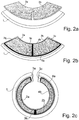
- the number of support plates forming a support layer 2 in the direction of rotation need not be limited to a single one-piece support plate, as in Fig. 1 but may be composed of a plurality of circumferentially juxtaposed partial support sheets or partial support layers, such. B. from two (s. Fig. 2 ), three or four (s. Fig. 3 ) and even more support plates, depending on the application and requirements for the connection between the support layer 2 and the support layer 1.
- This increases each additional cohesive connection along the other longitudinal edges 3c), 3d) in the form of connecting seams, the bond between the support layer 1 and the Pad layer 2 compared to a more positive connection, which is still effected between the seams.
- the partial overlay layers may have the same or different widths. This makes it possible, even for different diameters of the finished multilayer pipe to access in part standardized strips of the same or different width of partial support layers.
- a build-up welding in the area of the overlay layer 2 or between the partial overlay layers, the test of the overlay welding and, if necessary, their repair are by a maximum initial bending radius which is at least twice as large as the end radius of the multilayer pipe and thus allows free accessibility of the welds, favored.
- a further embodiment variant of the invention consists in that the regions of the carrier sheet which follow the longitudinal edges in the circumferential direction remain straight after the pre-bending; the pre-bent support plates are placed only up to the approach of the straight areas merging into the rounding and connected cohesively along its edges with the support plate.
- the remaining straight sections of the carrier sheet or the carrier layer 1 along the longitudinal edge of the support layer separated, so that a slot tube without straight sections in the edge region in the circumferential direction and, accordingly, a round multi-layer tube is obtained.
- a further embodiment variant is that the support layer 2 does not completely cover the carrier layer 1 in the circumferential direction in order to form a groove over a partial circle.
- the partial support layers or segments can be produced from different materials and / or also have different wall thicknesses (thicknesses). This enables application-specific optimization of the multilayer pipe. In this way, areas of the multilayer pipe subject to different stresses can be covered in terms of corrosion, wear and the like with matching corrosion or wear-resistant materials.
- the method described in its different variants makes it possible to use materials of the support layer 2 with a higher yield strength compared to the material of the carrier layer 1 in the manufacture of multilayer large pipes. This provides a further advantage over hydroforming liner liners made in a known manner when the liner material must have a lower yield strength so that after the expansion of the inner and outer tubes and the final joint shrinkage of the two tubes, a frictional connection is created.
Applications Claiming Priority (2)
| Application Number | Priority Date | Filing Date | Title |
|---|---|---|---|
| DE102013103811.5A DE102013103811B3 (de) | 2013-04-16 | 2013-04-16 | Verfahren zum Herstellen eines mehrlagigen Großrohres |
| PCT/EP2014/056059 WO2014170106A1 (de) | 2013-04-16 | 2014-03-26 | Verfahren zum herstellen eines mehrlagigen grossrohres |
Publications (2)
| Publication Number | Publication Date |
|---|---|
| EP2986402A1 EP2986402A1 (de) | 2016-02-24 |
| EP2986402B1 true EP2986402B1 (de) | 2017-03-01 |
Family
ID=50181996
Family Applications (1)
| Application Number | Title | Priority Date | Filing Date |
|---|---|---|---|
| EP14714231.9A Active EP2986402B1 (de) | 2013-04-16 | 2014-03-26 | Verfahren zum herstellen eines mehrlagigen grossrohres |
Country Status (10)
| Country | Link |
|---|---|
| US (1) | US10183320B2 (ko) |
| EP (1) | EP2986402B1 (ko) |
| JP (1) | JP6109406B2 (ko) |
| KR (1) | KR101758299B1 (ko) |
| CN (1) | CN105142814B (ko) |
| BR (1) | BR112015025557B1 (ko) |
| CY (1) | CY1118897T1 (ko) |
| DE (1) | DE102013103811B3 (ko) |
| MY (1) | MY184340A (ko) |
| WO (1) | WO2014170106A1 (ko) |
Families Citing this family (8)
| Publication number | Priority date | Publication date | Assignee | Title |
|---|---|---|---|---|
| DE102013103811B3 (de) | 2013-04-16 | 2014-03-20 | EISENBAU KRäMER GMBH | Verfahren zum Herstellen eines mehrlagigen Großrohres |
| DE102014108145A1 (de) | 2014-06-10 | 2015-12-17 | EISENBAU KRäMER GMBH | Verfahren zum Herstellen eines mehrlagigen Großrohres |
| DE202015101441U1 (de) | 2015-03-06 | 2016-06-08 | EISENBAU KRäMER GMBH | Vorrichtung zum Herstellen eines mehrlagigen Großrohres |
| CA2977433C (en) | 2015-03-06 | 2019-03-19 | Eisenbau Kramer Gmbh | Method and coating device for applying a cladding layer during the production of a multilayer heavy-duty pipe |
| DE102015103338B3 (de) * | 2015-03-06 | 2016-04-14 | EISENBAU KRäMER GMBH | Verfahren zum Herstellen eines mehrlagigen Großrohres |
| CN107962311B (zh) * | 2017-11-29 | 2020-05-19 | 郑博元 | 一种双金属复合内防腐管的制备方法 |
| DE102019130078A1 (de) * | 2019-11-07 | 2021-05-12 | Auto-Kabel Management Gmbh | Kraftfahrzeugenergieleitung sowie ein Verfahren zum Biegen einer Kraftfahrzeugenergieleitung |
| US20220040782A1 (en) * | 2020-08-04 | 2022-02-10 | Paul Po Cheng | Methods and systems for cladding |
Family Cites Families (20)
| Publication number | Priority date | Publication date | Assignee | Title |
|---|---|---|---|---|
| DE593559C (de) | 1934-02-28 | Theodor V Meszoely | Verfahren zur Herstellung von doppelwandigen Metallrohren | |
| US2288340A (en) | 1936-08-29 | 1942-06-30 | William S S Yates | Method of making composite tubular structures |
| JPS5865524A (ja) | 1981-10-16 | 1983-04-19 | Kawasaki Heavy Ind Ltd | 二重管製造方法 |
| JPS60111791A (ja) * | 1983-11-21 | 1985-06-18 | Kawasaki Steel Corp | 多重uoe管の製法 |
| BE1005554A3 (fr) * | 1991-12-10 | 1993-10-26 | Bundy Internat Ltd | Procede de fabrication d'un tube a paroi multiple. |
| US5657922A (en) * | 1995-07-14 | 1997-08-19 | Univ Oklahoma State | Machine and process for forming tapered or cylindrical utility poles from flat sheet metal |
| JPH11291030A (ja) * | 1998-04-07 | 1999-10-26 | Nkk Corp | チタンクラッド鋼被覆鋼管杭の製造方法 |
| DE10022823A1 (de) * | 2000-05-10 | 2001-11-22 | Unicor Extrusionstechnik Gmbh | Verfahren zur Herstellung von Mehrschicht-Metall-Verbundrohren |
| SE517435C2 (sv) | 2000-06-20 | 2002-06-04 | Claes Haakan Lundgren Med Plaa | Tillverkningsmetod för framställning av profilerade produkter som deformeras till slutlig form genom tryck mot ämnets vägg samt ämne |
| US7243717B2 (en) | 2002-08-05 | 2007-07-17 | Intelliserv, Inc. | Apparatus in a drill string |
| US6799632B2 (en) | 2002-08-05 | 2004-10-05 | Intelliserv, Inc. | Expandable metal liner for downhole components |
| AU2003902440A0 (en) | 2003-05-20 | 2003-06-05 | Cladtek International Pty Ltd | Production of clad pipes |
| BRPI0411204B1 (pt) * | 2003-07-21 | 2015-04-14 | Grant Prideco Lp | Dispositivo de componente tubular e conector e método para soldar um componente tubular e um conector |
| ES2308586T3 (es) * | 2004-12-21 | 2008-12-01 | Bergrohr Gmbh Siegen | Procedimiento para la fabricacion de un tubo multicapa. |
| US7694402B2 (en) | 2005-08-01 | 2010-04-13 | Packless Metal Hose, Inc. | Method for forming a lined conduit |
| DE102008024009A1 (de) * | 2008-05-16 | 2009-12-03 | Erndtebrücker Eisenwerk GmbH & Co. KG | Längsnahtgeschweißtes Mehrlagenrohr und Verfahren zur Herstellung eines längsnahtgeschweißten Mehrlagenrohres |
| DE102008027807B4 (de) | 2008-06-06 | 2011-05-12 | Eisenbau Krämer mbH | Verfahren zum Herstellen eines großen Stahlrohres |
| KR101179763B1 (ko) | 2009-05-07 | 2012-09-04 | 현대하이스코 주식회사 | 하이드로포밍을 이용한 다중복합강관 및 그 제조방법 |
| ATE520479T1 (de) | 2009-06-19 | 2011-09-15 | Bergrohr Gmbh Siegen | Produktionsoptimiertes verfahren zur herstellung eines mehrlagenrohres |
| DE102013103811B3 (de) | 2013-04-16 | 2014-03-20 | EISENBAU KRäMER GMBH | Verfahren zum Herstellen eines mehrlagigen Großrohres |
-
2013
- 2013-04-16 DE DE102013103811.5A patent/DE102013103811B3/de not_active Expired - Fee Related
-
2014
- 2014-03-26 WO PCT/EP2014/056059 patent/WO2014170106A1/de active Application Filing
- 2014-03-26 JP JP2016508066A patent/JP6109406B2/ja active Active
- 2014-03-26 EP EP14714231.9A patent/EP2986402B1/de active Active
- 2014-03-26 CN CN201480021807.1A patent/CN105142814B/zh active Active
- 2014-03-26 US US14/785,272 patent/US10183320B2/en active Active
- 2014-03-26 KR KR1020157032098A patent/KR101758299B1/ko active IP Right Grant
- 2014-03-26 BR BR112015025557-4A patent/BR112015025557B1/pt active IP Right Grant
- 2014-03-26 MY MYPI2015703659A patent/MY184340A/en unknown
-
2017
- 2017-05-12 CY CY20171100510T patent/CY1118897T1/el unknown
Also Published As
| Publication number | Publication date |
|---|---|
| DE102013103811B3 (de) | 2014-03-20 |
| KR20150140371A (ko) | 2015-12-15 |
| EP2986402A1 (de) | 2016-02-24 |
| US10183320B2 (en) | 2019-01-22 |
| CN105142814B (zh) | 2017-03-08 |
| CY1118897T1 (el) | 2018-01-10 |
| US20160082492A1 (en) | 2016-03-24 |
| JP6109406B2 (ja) | 2017-04-05 |
| JP2016518990A (ja) | 2016-06-30 |
| MY184340A (en) | 2021-04-01 |
| CN105142814A (zh) | 2015-12-09 |
| BR112015025557B1 (pt) | 2020-12-08 |
| BR112015025557A2 (pt) | 2017-07-18 |
| KR101758299B1 (ko) | 2017-07-14 |
| WO2014170106A1 (de) | 2014-10-23 |
Similar Documents
| Publication | Publication Date | Title |
|---|---|---|
| EP2986402B1 (de) | Verfahren zum herstellen eines mehrlagigen grossrohres | |
| EP1827727B9 (de) | Verfahren zur Herstellung eines Mehrlagenrohres | |
| EP1954420B1 (de) | Verfahren und vorrichtung zum kernlosen einformen von hohlprofilen | |
| EP1775437B1 (de) | Hitzeschild in Sandwich-Bauweise | |
| WO2014033037A1 (de) | Verfahren und vorrichtung zum verbinden von metallbändern | |
| EP2931449B1 (de) | Verfahren zur herstellung eines endlosbandes | |
| DE102014108145A1 (de) | Verfahren zum Herstellen eines mehrlagigen Großrohres | |
| EP2285508B1 (de) | Produktionsoptimiertes verfahren zur herstellung eines mehrlagenrohres | |
| EP2729679A1 (de) | Verfahren zur herstellung einer abgasanlage sowie abgasanlage | |
| EP2205371B1 (de) | Verfahren zur herstellung von rohr-in-rohr-systemen | |
| EP2903757B1 (de) | Verfahren zur schnellen herstellung eines mehrlagenrohres | |
| EP2667073B1 (de) | Rohrstück aus Metallblech, Verfahren zu dessen Herstellung und Verfahren zur Herstellung eines Rohrbogens | |
| EP2492028A2 (de) | Verfahren zum Aufbringen einer Rosette auf ein Rohr | |
| DE102020116508B4 (de) | Verbinden von Blechendabschnitten mittels Umformens | |
| DE102012009845A1 (de) | Rohrstück aus Metallblech und Verfahren zu dessen Herstellung, Streck-Biegevorrichtung zur Herstellung eines Rohrbogens und Verfahren zur Herstellung eines Rohrbogens | |
| EP2508833A2 (de) | Verdampferplatte für eine Kältemaschine | |
| EP0186130B1 (de) | Verfahren zur Herstellung zylindrische Wärmetauschersammelrohrstrukturen bildender ringscheibenartiger Bauteile | |
| WO2011110195A1 (de) | Einformstrasse und verfahren zur herstellung eines mehrlagenrohres | |
| EP1849560B1 (de) | Presswerkzeug mit schichtförmigem Pressbackenelement | |
| WO2012113633A1 (de) | Rückschluss, insbesondere für eine elektrische maschine und verfahren zur herstellung eines rückschlusses für einen rotor oder stator einer elektrischen maschine | |
| DE102021106434A1 (de) | Fertigungslinie und Verfahren zur Herstellung von Kurzrohren aus metallischem Werkstoff | |
| WO2019068119A1 (de) | Verfahren zum verbinden flächiger bauteile sowie verbundelement | |
| DE102021110492A1 (de) | Vorrichtung und Verfahren zur Herstellung eines doppelwandigen Rohres |
Legal Events
| Date | Code | Title | Description |
|---|---|---|---|
| PUAI | Public reference made under article 153(3) epc to a published international application that has entered the european phase |
Free format text: ORIGINAL CODE: 0009012 |
|
| 17P | Request for examination filed |
Effective date: 20151116 |
|
| AK | Designated contracting states |
Kind code of ref document: A1 Designated state(s): AL AT BE BG CH CY CZ DE DK EE ES FI FR GB GR HR HU IE IS IT LI LT LU LV MC MK MT NL NO PL PT RO RS SE SI SK SM TR |
|
| AX | Request for extension of the european patent |
Extension state: BA ME |
|
| DAX | Request for extension of the european patent (deleted) | ||
| GRAP | Despatch of communication of intention to grant a patent |
Free format text: ORIGINAL CODE: EPIDOSNIGR1 |
|
| INTG | Intention to grant announced |
Effective date: 20161201 |
|
| GRAS | Grant fee paid |
Free format text: ORIGINAL CODE: EPIDOSNIGR3 |
|
| GRAA | (expected) grant |
Free format text: ORIGINAL CODE: 0009210 |
|
| AK | Designated contracting states |
Kind code of ref document: B1 Designated state(s): AL AT BE BG CH CY CZ DE DK EE ES FI FR GB GR HR HU IE IS IT LI LT LU LV MC MK MT NL NO PL PT RO RS SE SI SK SM TR |
|
| REG | Reference to a national code |
Ref country code: GB Ref legal event code: FG4D Free format text: NOT ENGLISH |
|
| REG | Reference to a national code |
Ref country code: CH Ref legal event code: EP Ref country code: AT Ref legal event code: REF Ref document number: 870670 Country of ref document: AT Kind code of ref document: T Effective date: 20170315 |
|
| REG | Reference to a national code |
Ref country code: IE Ref legal event code: FG4D Free format text: LANGUAGE OF EP DOCUMENT: GERMAN Ref country code: FR Ref legal event code: PLFP Year of fee payment: 4 |
|
| REG | Reference to a national code |
Ref country code: DE Ref legal event code: R096 Ref document number: 502014002848 Country of ref document: DE |
|
| REG | Reference to a national code |
Ref country code: NO Ref legal event code: T2 Effective date: 20170301 |
|
| REG | Reference to a national code |
Ref country code: NL Ref legal event code: MP Effective date: 20170301 |
|
| REG | Reference to a national code |
Ref country code: LT Ref legal event code: MG4D |
|
| PG25 | Lapsed in a contracting state [announced via postgrant information from national office to epo] |
Ref country code: LT Free format text: LAPSE BECAUSE OF FAILURE TO SUBMIT A TRANSLATION OF THE DESCRIPTION OR TO PAY THE FEE WITHIN THE PRESCRIBED TIME-LIMIT Effective date: 20170301 Ref country code: FI Free format text: LAPSE BECAUSE OF FAILURE TO SUBMIT A TRANSLATION OF THE DESCRIPTION OR TO PAY THE FEE WITHIN THE PRESCRIBED TIME-LIMIT Effective date: 20170301 Ref country code: HR Free format text: LAPSE BECAUSE OF FAILURE TO SUBMIT A TRANSLATION OF THE DESCRIPTION OR TO PAY THE FEE WITHIN THE PRESCRIBED TIME-LIMIT Effective date: 20170301 Ref country code: GR Free format text: LAPSE BECAUSE OF FAILURE TO SUBMIT A TRANSLATION OF THE DESCRIPTION OR TO PAY THE FEE WITHIN THE PRESCRIBED TIME-LIMIT Effective date: 20170602 |
|
| PG25 | Lapsed in a contracting state [announced via postgrant information from national office to epo] |
Ref country code: LV Free format text: LAPSE BECAUSE OF FAILURE TO SUBMIT A TRANSLATION OF THE DESCRIPTION OR TO PAY THE FEE WITHIN THE PRESCRIBED TIME-LIMIT Effective date: 20170301 Ref country code: RS Free format text: LAPSE BECAUSE OF FAILURE TO SUBMIT A TRANSLATION OF THE DESCRIPTION OR TO PAY THE FEE WITHIN THE PRESCRIBED TIME-LIMIT Effective date: 20170301 Ref country code: ES Free format text: LAPSE BECAUSE OF FAILURE TO SUBMIT A TRANSLATION OF THE DESCRIPTION OR TO PAY THE FEE WITHIN THE PRESCRIBED TIME-LIMIT Effective date: 20170301 Ref country code: SE Free format text: LAPSE BECAUSE OF FAILURE TO SUBMIT A TRANSLATION OF THE DESCRIPTION OR TO PAY THE FEE WITHIN THE PRESCRIBED TIME-LIMIT Effective date: 20170301 Ref country code: BG Free format text: LAPSE BECAUSE OF FAILURE TO SUBMIT A TRANSLATION OF THE DESCRIPTION OR TO PAY THE FEE WITHIN THE PRESCRIBED TIME-LIMIT Effective date: 20170601 |
|
| REG | Reference to a national code |
Ref country code: DE Ref legal event code: R082 Ref document number: 502014002848 Country of ref document: DE Representative=s name: PATENTANWAELTE JECK, FLECK & PARTNER MBB, DE Ref country code: DE Ref legal event code: R082 Ref document number: 502014002848 Country of ref document: DE Representative=s name: JECK - FLECK PATENTANWAELTE, DE |
|
| PG25 | Lapsed in a contracting state [announced via postgrant information from national office to epo] |
Ref country code: NL Free format text: LAPSE BECAUSE OF FAILURE TO SUBMIT A TRANSLATION OF THE DESCRIPTION OR TO PAY THE FEE WITHIN THE PRESCRIBED TIME-LIMIT Effective date: 20170301 |
|
| PG25 | Lapsed in a contracting state [announced via postgrant information from national office to epo] |
Ref country code: RO Free format text: LAPSE BECAUSE OF FAILURE TO SUBMIT A TRANSLATION OF THE DESCRIPTION OR TO PAY THE FEE WITHIN THE PRESCRIBED TIME-LIMIT Effective date: 20170301 Ref country code: CZ Free format text: LAPSE BECAUSE OF FAILURE TO SUBMIT A TRANSLATION OF THE DESCRIPTION OR TO PAY THE FEE WITHIN THE PRESCRIBED TIME-LIMIT Effective date: 20170301 Ref country code: SK Free format text: LAPSE BECAUSE OF FAILURE TO SUBMIT A TRANSLATION OF THE DESCRIPTION OR TO PAY THE FEE WITHIN THE PRESCRIBED TIME-LIMIT Effective date: 20170301 Ref country code: EE Free format text: LAPSE BECAUSE OF FAILURE TO SUBMIT A TRANSLATION OF THE DESCRIPTION OR TO PAY THE FEE WITHIN THE PRESCRIBED TIME-LIMIT Effective date: 20170301 |
|
| REG | Reference to a national code |
Ref country code: CH Ref legal event code: PL |
|
| PG25 | Lapsed in a contracting state [announced via postgrant information from national office to epo] |
Ref country code: IS Free format text: LAPSE BECAUSE OF FAILURE TO SUBMIT A TRANSLATION OF THE DESCRIPTION OR TO PAY THE FEE WITHIN THE PRESCRIBED TIME-LIMIT Effective date: 20170701 Ref country code: PL Free format text: LAPSE BECAUSE OF FAILURE TO SUBMIT A TRANSLATION OF THE DESCRIPTION OR TO PAY THE FEE WITHIN THE PRESCRIBED TIME-LIMIT Effective date: 20170301 Ref country code: PT Free format text: LAPSE BECAUSE OF FAILURE TO SUBMIT A TRANSLATION OF THE DESCRIPTION OR TO PAY THE FEE WITHIN THE PRESCRIBED TIME-LIMIT Effective date: 20170703 Ref country code: SM Free format text: LAPSE BECAUSE OF FAILURE TO SUBMIT A TRANSLATION OF THE DESCRIPTION OR TO PAY THE FEE WITHIN THE PRESCRIBED TIME-LIMIT Effective date: 20170301 |
|
| REG | Reference to a national code |
Ref country code: DE Ref legal event code: R097 Ref document number: 502014002848 Country of ref document: DE |
|
| REG | Reference to a national code |
Ref country code: IE Ref legal event code: MM4A |
|
| PLBE | No opposition filed within time limit |
Free format text: ORIGINAL CODE: 0009261 |
|
| STAA | Information on the status of an ep patent application or granted ep patent |
Free format text: STATUS: NO OPPOSITION FILED WITHIN TIME LIMIT |
|
| PG25 | Lapsed in a contracting state [announced via postgrant information from national office to epo] |
Ref country code: DK Free format text: LAPSE BECAUSE OF FAILURE TO SUBMIT A TRANSLATION OF THE DESCRIPTION OR TO PAY THE FEE WITHIN THE PRESCRIBED TIME-LIMIT Effective date: 20170301 Ref country code: LU Free format text: LAPSE BECAUSE OF NON-PAYMENT OF DUE FEES Effective date: 20170326 Ref country code: MC Free format text: LAPSE BECAUSE OF FAILURE TO SUBMIT A TRANSLATION OF THE DESCRIPTION OR TO PAY THE FEE WITHIN THE PRESCRIBED TIME-LIMIT Effective date: 20170301 |
|
| 26N | No opposition filed |
Effective date: 20171204 |
|
| PG25 | Lapsed in a contracting state [announced via postgrant information from national office to epo] |
Ref country code: IE Free format text: LAPSE BECAUSE OF NON-PAYMENT OF DUE FEES Effective date: 20170326 Ref country code: LI Free format text: LAPSE BECAUSE OF NON-PAYMENT OF DUE FEES Effective date: 20170331 Ref country code: CH Free format text: LAPSE BECAUSE OF NON-PAYMENT OF DUE FEES Effective date: 20170331 Ref country code: SI Free format text: LAPSE BECAUSE OF FAILURE TO SUBMIT A TRANSLATION OF THE DESCRIPTION OR TO PAY THE FEE WITHIN THE PRESCRIBED TIME-LIMIT Effective date: 20170301 |
|
| REG | Reference to a national code |
Ref country code: BE Ref legal event code: MM Effective date: 20170331 |
|
| REG | Reference to a national code |
Ref country code: FR Ref legal event code: PLFP Year of fee payment: 5 |
|
| PG25 | Lapsed in a contracting state [announced via postgrant information from national office to epo] |
Ref country code: BE Free format text: LAPSE BECAUSE OF NON-PAYMENT OF DUE FEES Effective date: 20170331 |
|
| PGFP | Annual fee paid to national office [announced via postgrant information from national office to epo] |
Ref country code: NO Payment date: 20180323 Year of fee payment: 5 |
|
| PG25 | Lapsed in a contracting state [announced via postgrant information from national office to epo] |
Ref country code: MT Free format text: LAPSE BECAUSE OF FAILURE TO SUBMIT A TRANSLATION OF THE DESCRIPTION OR TO PAY THE FEE WITHIN THE PRESCRIBED TIME-LIMIT Effective date: 20170301 |
|
| PGFP | Annual fee paid to national office [announced via postgrant information from national office to epo] |
Ref country code: CY Payment date: 20180322 Year of fee payment: 5 |
|
| PG25 | Lapsed in a contracting state [announced via postgrant information from national office to epo] |
Ref country code: HU Free format text: LAPSE BECAUSE OF FAILURE TO SUBMIT A TRANSLATION OF THE DESCRIPTION OR TO PAY THE FEE WITHIN THE PRESCRIBED TIME-LIMIT; INVALID AB INITIO Effective date: 20140326 |
|
| REG | Reference to a national code |
Ref country code: NO Ref legal event code: MMEP |
|
| PG25 | Lapsed in a contracting state [announced via postgrant information from national office to epo] |
Ref country code: CY Free format text: LAPSE BECAUSE OF NON-PAYMENT OF DUE FEES Effective date: 20190326 |
|
| PG25 | Lapsed in a contracting state [announced via postgrant information from national office to epo] |
Ref country code: MK Free format text: LAPSE BECAUSE OF FAILURE TO SUBMIT A TRANSLATION OF THE DESCRIPTION OR TO PAY THE FEE WITHIN THE PRESCRIBED TIME-LIMIT Effective date: 20170301 |
|
| PG25 | Lapsed in a contracting state [announced via postgrant information from national office to epo] |
Ref country code: NO Free format text: LAPSE BECAUSE OF NON-PAYMENT OF DUE FEES Effective date: 20190331 |
|
| PG25 | Lapsed in a contracting state [announced via postgrant information from national office to epo] |
Ref country code: TR Free format text: LAPSE BECAUSE OF FAILURE TO SUBMIT A TRANSLATION OF THE DESCRIPTION OR TO PAY THE FEE WITHIN THE PRESCRIBED TIME-LIMIT Effective date: 20170301 |
|
| PG25 | Lapsed in a contracting state [announced via postgrant information from national office to epo] |
Ref country code: AL Free format text: LAPSE BECAUSE OF FAILURE TO SUBMIT A TRANSLATION OF THE DESCRIPTION OR TO PAY THE FEE WITHIN THE PRESCRIBED TIME-LIMIT Effective date: 20170301 |
|
| REG | Reference to a national code |
Ref country code: AT Ref legal event code: MM01 Ref document number: 870670 Country of ref document: AT Kind code of ref document: T Effective date: 20190326 |
|
| PG25 | Lapsed in a contracting state [announced via postgrant information from national office to epo] |
Ref country code: AT Free format text: LAPSE BECAUSE OF NON-PAYMENT OF DUE FEES Effective date: 20190326 |
|
| PGFP | Annual fee paid to national office [announced via postgrant information from national office to epo] |
Ref country code: FR Payment date: 20230324 Year of fee payment: 10 |
|
| PGFP | Annual fee paid to national office [announced via postgrant information from national office to epo] |
Ref country code: GB Payment date: 20230322 Year of fee payment: 10 Ref country code: DE Payment date: 20230321 Year of fee payment: 10 |
|
| PGFP | Annual fee paid to national office [announced via postgrant information from national office to epo] |
Ref country code: IT Payment date: 20230328 Year of fee payment: 10 |
|
| PGFP | Annual fee paid to national office [announced via postgrant information from national office to epo] |
Ref country code: DE Payment date: 20240320 Year of fee payment: 11 Ref country code: GB Payment date: 20240320 Year of fee payment: 11 |