EP2985207B1 - Dispositif et procédé de commande de direction - Google Patents
Dispositif et procédé de commande de direction Download PDFInfo
- Publication number
- EP2985207B1 EP2985207B1 EP13882023.8A EP13882023A EP2985207B1 EP 2985207 B1 EP2985207 B1 EP 2985207B1 EP 13882023 A EP13882023 A EP 13882023A EP 2985207 B1 EP2985207 B1 EP 2985207B1
- Authority
- EP
- European Patent Office
- Prior art keywords
- steering
- assist torque
- vehicle
- speed
- steering assist
- Prior art date
- Legal status (The legal status is an assumption and is not a legal conclusion. Google has not performed a legal analysis and makes no representation as to the accuracy of the status listed.)
- Not-in-force
Links
- 238000000034 method Methods 0.000 title claims description 5
- 230000007935 neutral effect Effects 0.000 claims description 37
- 238000006557 surface reaction Methods 0.000 claims description 22
- 238000001514 detection method Methods 0.000 claims description 12
- 230000001133 acceleration Effects 0.000 claims description 10
- 230000015654 memory Effects 0.000 description 28
- 238000012937 correction Methods 0.000 description 24
- 238000010586 diagram Methods 0.000 description 14
- 230000007423 decrease Effects 0.000 description 13
- 230000008859 change Effects 0.000 description 11
- 230000000694 effects Effects 0.000 description 10
- 230000006870 function Effects 0.000 description 7
- 238000012545 processing Methods 0.000 description 7
- 230000009467 reduction Effects 0.000 description 6
- 230000007246 mechanism Effects 0.000 description 5
- 238000006243 chemical reaction Methods 0.000 description 2
- 230000003247 decreasing effect Effects 0.000 description 2
- 229920006395 saturated elastomer Polymers 0.000 description 2
- 230000000087 stabilizing effect Effects 0.000 description 2
- 238000012935 Averaging Methods 0.000 description 1
- 238000013459 approach Methods 0.000 description 1
- 238000010248 power generation Methods 0.000 description 1
- 230000003252 repetitive effect Effects 0.000 description 1
- 230000004044 response Effects 0.000 description 1
Images


Classifications
-
- B—PERFORMING OPERATIONS; TRANSPORTING
- B62—LAND VEHICLES FOR TRAVELLING OTHERWISE THAN ON RAILS
- B62D—MOTOR VEHICLES; TRAILERS
- B62D5/00—Power-assisted or power-driven steering
- B62D5/04—Power-assisted or power-driven steering electrical, e.g. using an electric servo-motor connected to, or forming part of, the steering gear
- B62D5/0457—Power-assisted or power-driven steering electrical, e.g. using an electric servo-motor connected to, or forming part of, the steering gear characterised by control features of the drive means as such
- B62D5/046—Controlling the motor
- B62D5/0463—Controlling the motor calculating assisting torque from the motor based on driver input
-
- B—PERFORMING OPERATIONS; TRANSPORTING
- B62—LAND VEHICLES FOR TRAVELLING OTHERWISE THAN ON RAILS
- B62D—MOTOR VEHICLES; TRAILERS
- B62D5/00—Power-assisted or power-driven steering
- B62D5/04—Power-assisted or power-driven steering electrical, e.g. using an electric servo-motor connected to, or forming part of, the steering gear
- B62D5/0457—Power-assisted or power-driven steering electrical, e.g. using an electric servo-motor connected to, or forming part of, the steering gear characterised by control features of the drive means as such
- B62D5/046—Controlling the motor
- B62D5/0466—Controlling the motor for returning the steering wheel to neutral position
Definitions
- the present invention relates to a steering control device, and the like, for assisting steering by a driver.
- a steering wheel return torque is generated by a motor in order to improve steering wheel return characteristics at the time when a driver releases a steering wheel from his/her hand at low vehicle speed.
- Patent Literature 1 a predefined function of a target return speed for a steering angle is selected based on an average feed speed and a vehicle speed, and drive control is performed by assist power generation means so that a return speed of the steering wheel becomes the calculated target return speed.
- the average feed speed is calculated based on a deviation between a steering angle at the start of the feed of the steering wheel and a steering angle at the end of the feed of the steering wheel and an elapsed time of the feed of the steering wheel.
- the target return speed is changed through the feed of the steering wheel.
- a steering-holding state of a steering wheel is determined based on a steering torque and a steering speed, and when it is determined that the steering is held, an output of steering wheel return control is set to be zero. In this manner, the steering torque is prevented from being increased at the time when the steering of the steering wheel is held.
- WO 2013/005092 A1 describes a steering system which includes: a steering member that is provided on a vehicle and that is used for a steering operation; an actuator that assists the steering operation of the steering member; and a steering control device that executes returning operation assist control in which the actuator is controlled to assist a returning operation for returning the steering member to a neutral position, the returning operation corresponding to a turning operation for turning the steering member from the neutral position, and that determines a returning operation time at the time of executing the returning operation assist control on the basis of a steering operation amount of the steering member (5) at the time of the turning operation.
- the target return speed or the return torque cannot be appropriately adjusted depending on the magnitude of a state amount representing a turning state of the vehicle at the time when the driver releases the steering wheel from his/her hand or turns back the steering wheel, for example, depending on the magnitude of a steering angle at the time when the driver releases the steering wheel from his/her hand.
- the increase in steering torque can be suppressed when it is determined that the steering is held, but the return torque is increased at the start of the feed of steering. Thus, the driver may have a feel of discomfort.
- the present invention has been made in order to solve the problems as described above, and has an object of providing a steering control device and the like, which are capable of acquiring an appropriate steering assist torque irrespective of a position of a steering wheel at the time when a driver turns back the steering wheel or releases the steering wheel from his/her hand.
- a steering control device and the like including: an actuator for applying a steering assist torque to a steering system of a vehicle; a vehicle turning state detection section for detecting a state amount representing a turning state of the vehicle; a steering-holding determination section for determining a steering-holding state of the steering system; a storing section for storing, when the steering-holding determination section determines the steering-holding state, the state amount detected by the vehicle turning state detection section as a steering-holding determination state amount; a steering assist torque calculation section for calculating the steering assist torque based on an absolute value of the steering-holding determination state amount; and an actuator control section for controlling the actuator based on the calculated steering assist torque.
- the steering assist torque may be changed depending on the magnitude of the steering-holding determination state amount. Consequently, an appropriate steering assist torque may be acquired irrespective of the position of the steering wheel at the time when the driver turns back the steering wheel or releases the steering wheel from his/her hand, and therefore an appropriate return of the steering wheel and an appropriate steering feeling may be realized.
- FIG. 1 is a diagram for illustrating an example of a configuration of the steering control device according to the present invention.
- Right and left steered wheels 3 are steered in response to rotation of a steering shaft 2 coupled to a steering wheel 1.
- a steering angle sensor 4 for detecting a steering angle is mounted to the steering wheel 1.
- a torque sensor 5 is mounted to the steering shaft 2 to detect a steering torque acting on the steering shaft 2.
- a motor 6 is coupled to the steering shaft 2 via a speed reduction mechanism 7, and can apply a steering assist torque generated by the motor 6 to the steering shaft 2.
- a vehicle speed of a vehicle is detected by a vehicle speed sensor 8.
- a current flowing through the motor 6 is detected by a current sensor 9.
- An inter-terminal voltage of the motor 6 is detected by a voltage sensor 10.
- a control unit 11 calculates, for example, the steering assist torque to be generated by the motor 6, and controls the current of the motor 6 necessary for generating the steering assist torque.
- the control unit 11 includes a microcomputer (CPU) constructed by memories including a ROM and a RAM to be described later, a current driver for driving the motor current (causing a desired current to flow through the motor 6), and the like.
- the control unit 11 includes a steering-holding determination device 22, a steering assist torque calculator 24, a storing device 23, and a memory M, which are constructed by the microcomputer, and a current driver 12. Then, a vehicle turning state detector 21 including the steering angle sensor 4, for example, and the vehicle speed sensor 8 and the torque sensor 5 are connected to the control unit 11.
- the storing device 23 writes and reads necessary data to and from the memory M, which is a recording medium.
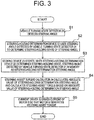
- Step S1 the steering angle sensor 4 is used as the vehicle turning state detector 21 to detect a steering angle.
- the steering angle is used as a state amount representing a turning state of the vehicle.
- the steering-holding determination device 22 determines a steering-holding state of a steering system of the vehicle, that is, whether or not the steering wheel 1 remains at a substantially constant steering angle. In the steering-holding determination, the steering-holding determination device 22 uses the steering angle detected by the vehicle turning state detector 21 to calculate a steering speed based on the steering angle, and determines a situation in which the magnitude of the steering speed is smaller than a predetermined steering speed threshold as the steering-holding state.
- the storing device 23 stores a value detected by the vehicle turning state detector 21 at the time when the steering-holding determination device 22 determines the steering-holding state in the memory M as a steering-holding determination state amount.
- the storing device 23 stores the steering angle detected by the steering angle sensor 4 at the time when the steering-holding determination device 22 determines the steering-holding state in the memory M as a steering-holding determination steering angle (first stored value).
- a predetermined stored value is stored in the memory M in advance as an initial value of the steering-holding determination steering angle.
- the predetermined stored value is zero.
- the storing device 23 updates the stored steering-holding determination state amount, and stores the updated steering-holding determination state amount.
- the steering-holding determination device 22 updates the steering-holding determination state amount to a predetermined second stored value, and stores the predetermined second stored value.
- the predetermined second stored value is zero.
- the steering-holding determination device 22 updates the steering-holding determination state amount to the second stored value as zero, and stores the second stored value.
- Step 4 S4 the steering assist torque calculator 24 calculates the magnitude of the steering-holding determination state amount, that is, an absolute value of the steering-holding determination steering angle, and calculates a steering assist torque based on the absolute value of the steering-holding determination steering angle.
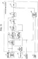
- FIG. 4 A block diagram of the steering assist torque calculator 24 is illustrated in FIG. 4 , and an operation flowchart thereof is illustrated in FIG. 5 . Note that, the operation illustrated in the operation flowchart is repeatedly executed at a control cycle of a predetermined period. In this embodiment, a steering angle is used as an input signal used in the steering assist torque calculator 24.
- the steering assist torque calculator 24 includes an absolute value calculator 31, a state amount corrector 32, a first target steering speed setter 33, a second target steering speed setter 34, a weighting device 35, a gain corrector 36, a sign corrector 37, a steering speed calculator 38, a speed controller 39, a steering assist torque-2 calculator 40, and an adder 41.
- the absolute value calculator 31 calculates the magnitude of the steering-holding determination state amount. In other words, the absolute value calculator 31 calculates the absolute value of the steering-holding determination state amount. In this embodiment, the absolute value calculator 31 calculates the absolute value of the steering-holding determination steering angle, which is stored in the memory by the storing device 23.
- Step S22 the state amount corrector 32 corrects the steering angle based on the absolute value of the steering-holding determination state amount, to thereby calculate the corrected steering angle.
- processing expressed by Expression (1) is performed.
- ⁇ h 1 ⁇ h ⁇ ⁇ n /
- the reference steering angle ⁇ n may be stored in the memory in advance, and the stored reference steering angle ⁇ n may be used.
- Expression (1) represents the calculation of a steering angle corresponding to the case where the absolute value
- Step S23 the first target steering speed setter 33 sets a first target steering speed corresponding to the corrected steering angle.
- first target steering speed information corresponding to steering angles of from zero to the reference steering angle is stored in the memory M in advance as map information.
- the first target steering speed setter 33 calculates a first target steering speed d ⁇ ref1 corresponding to the corrected steering angle ⁇ h1.
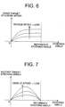
- FIG. 6 An example of the map information on the first target steering speed information is shown in FIG. 6 .
- a target steering speed is stored in the memory in association with a vehicle speed Vel, and the first target steering speed is set depending on the corrected steering angle and the vehicle speed.
- the three curves of FIG. 6 represent the first target steering speeds corresponding to the steering angles of from zero to the reference steering angle for three kinds of vehicle speeds (the vehicle speed is lower in order from bottom to top), respectively.
- the first target steering speed has such characteristics that the target steering speed increases along with an increase in steering angle.
- the first target steering speed has such characteristics that the first target steering speed decreases along with an increase in vehicle speed.
- the first target steering speed may be set as a function as expressed by Expression (2) instead of the map information.
- d ⁇ ref 1 f 1 ⁇ h 1, Vel
- Step S24 the second target steering speed setter 34 sets a second target steering speed d ⁇ ref2 corresponding to the corrected steering angle.
- second target steering speed information corresponding to steering angles of from zero to the reference steering angle is stored in the memory M in advance as map information.
- the second target steering speed setter 34 calculates the second target steering speed d ⁇ ref2 corresponding to the corrected steering angle ⁇ h1.
- FIG. 7 An example of the map information on the second target steering speed information is shown in FIG. 7 .
- a target steering speed is stored in the memory in association with the vehicle speed Vel, and the second target steering speed is set depending on the corrected steering angle and the vehicle speed.
- the second target steering speed has such characteristics that the second target steering speed decreases along with an increase in vehicle speed.
- the three curves of FIG. 7 represent the second target steering speeds corresponding to the steering angles of from zero to the reference steering angle for three kinds of vehicle speeds (the vehicle speed is lower in order from bottom to top), respectively.
- the second target steering speed has such characteristics that, under the same vehicle speed, the second target steering speed first increases along with an increase in steering angle but subsequently decreases after reaching the maximum target steering speed.
- the second target steering speed may be set as a function as expressed by Expression (3) instead of the map information.
- d ⁇ ref 2 f 2 ⁇ h 1, Vel
- Step S22, Step S23, and Step S24 the steering angle to be input to the map is corrected, but as an alternative to this processing, instead of the steering angle, preset steering angles on the horizontal axis in the map information, that is, steering angles of from zero to the reference steering angle may be corrected. It means that an input signal to be calculated is corrected depending on the magnitude of the steering-holding determination state amount, and the steering assist torque is calculated based on the corrected input signal.
- Step S25 the weighting device 35 weights the first target steering speed and the second target steering speed based on the absolute value
- An example of a weighting W1 used in the weighting device 35 is shown in FIG. 8 .
- Data on the weighting W1 is stored, for example, in the memory M in advance.
- Data of FIG. 8 is stored, for example, in the memory M in advance.
- the weighting W1 is set to be 1 in a region in which the absolute value of the steering-holding determination steering angle is small, and the weighting W1 is set so as to approach 0 as the absolute value of the steering-holding determination steering angle becomes larger. Further, W1 is changed depending on the vehicle speed.
- the three curves of FIG. 8 represent the weightings for three kinds of vehicle speeds (the vehicle speed is lower in order from left to right), respectively.
- the weighting W1 becomes larger as the vehicle speed becomes lower.
- the first target steering speed d ⁇ ref1 is mainly set as the third target steering speed d ⁇ ref3
- the second target steering speed d ⁇ ref2 is mainly set as the third target steering speed d ⁇ ref3.
- the third target steering speed d ⁇ ref3 is a target return speed obtained by averaging the first target steering speed d ⁇ ref1 and the second target steering speed d ⁇ ref2.
- the weighting W1 changes continuously from 0 to 1, but a switch (not shown) may be used or the steering-holding determination steering angle may be compared to a predetermined threshold so as to select one of the first target steering speed d ⁇ ref1 and the second target steering speed d ⁇ ref2 depending on the magnitude of the steering-holding determination steering angle, to thereby set the third target steering speed d ⁇ ref3.
- Step S26 the gain corrector 36 sets a correction gain based on the absolute value
- An example of a correction gain W2 used in the gain corrector 36 is shown in FIG. 9 .
- Data on the correction gain W2 is stored, for example, in the memory M in advance.
- the correction gain W2 is set so as to be larger as the absolute value
- the fourth target steering speed d ⁇ ref4 is calculated by Expression (5).
- d ⁇ ref 4 W 2 ⁇ d ⁇ ref 3
- Step S27 the sign corrector 37 sets the sign of the fourth target steering speed d ⁇ ref4 based on the sign of the steering angle, to thereby obtain a fifth target steering speed d ⁇ ref5.
- the target steering speed is used for the purpose of appropriately returning the steering wheel to a neutral position when the driver releases the steering wheel 1 from his/her hand or returns the steering wheel 1, namely a steering operation of returning the steering wheel from a certain steering angle toward the neutral position, and hence the sign of the target steering speed is set to be opposite to the sign of the steering angle.
- the steering speed calculator 38 calculates a steering speed d ⁇ act based on the steering angle ⁇ h. Specifically, the steering speed calculator 38 calculates the steering speed by differentiating the steering angle detected by the steering angle sensor 4. Note that, the steering speed may be calculated by differentiating a rotation angle of the motor 6 and thereafter taking the speed reduction ratio of the speed reduction mechanism 7 into consideration. Alternatively, the steering speed may be estimated based on an induced voltage of the motor 6 (acquired from the voltage sensor 10) or the like.
- Step S29 the speed controller 39 calculates a steering assist torque-1 so that the steering speed follows the fifth target steering speed d ⁇ ref5.
- a deviation between the target steering speed d ⁇ ref5 and the steering speed d ⁇ act is multiplied by a feedback gain Kp to calculate the steering assist torque-1 (Ta1).
- Ta 1 Kp ⁇ d ⁇ ref 5 ⁇ d ⁇ act
- the magnitude thereof is limited.
- the magnitude is limited to be Ta1_max.
- the threshold Ta1_max is set to such a magnitude that the driver is capable of steering the steering wheel 1 while resisting the steering assist torque-1 (Ta1).
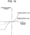
- the steering assist torque-2 calculator 40 calculates a steering assist torque-2 that is based at least on the steering torque. For example, a relationship between the vehicle speed Vel and the steering assist torque-2 with respect to the steering torque as shown in an assist map of FIG. 10 is stored in the memory M in advance, and the steering assist torque-2 calculator 40 sets the steering assist torque-2 (Ta2) depending on the steering torque from the torque sensor 5 and the vehicle speed Vel from the vehicle speed sensor 8.
- Step S31 the adder 41 adds the steering assist torque-1 (Ta1) and the steering assist torque-2 (Ta2) together, to thereby finally calculate the steering assist torque to be generated by the motor 6.
- Step S5 the current driver 12 drives the current of the motor 6 so that the motor 6 generates the calculated steering assist torque.
- the current driver 12 performs current control of the motor 6.
- the current driver 12 performs current control of the motor 6 so that the calculated steering assist torque is transmitted to the steering system via the speed reduction mechanism 7.
- the steering assist torque calculator 24 corrects the steering angle ⁇ h based on the absolute value
- the first and second target steering speeds d ⁇ ref1 and d ⁇ ref2 are weighted by the weighting W1 so that the first target steering speed d ⁇ ref1 is dominant in the region in which the absolute value of the steering-holding determination steering angle is small and that the second target steering speed d ⁇ ref2 is dominant in the region in which the absolute value of the steering-holding determination steering angle is large, and the resultants are added together, to thereby set the third target steering speed d ⁇ ref3.
- the third target steering speed d ⁇ ref3 is then corrected by the correction gain W2, which becomes larger as the absolute value of the steering-holding determination steering angle becomes larger, to thereby set the fourth target steering speed d ⁇ ref4.
- the fifth target steering speed d ⁇ ref5 obtained by converting the fourth target steering speed d ⁇ ref4 to have the opposite sign is set.
- the deviation between the fifth target steering speed d ⁇ ref5 and the steering speed d ⁇ act calculated based on the steering angle ⁇ h is multiplied by the feedback gain Kp, to thereby determine the steering assist torque-1 (Ta1) so that the steering speed follows the fifth target steering speed d ⁇ ref5.
- the steering assist torque-1 (Ta1) and the steering assist torque-2 (Ta2) which is determined from the assist map ( FIG. 10 ) based on the vehicle speed and the steering torque, are added together to calculate the steering assist torque to be generated by the motor 6.
- the steering-holding determination device 22 can detect the start of the return steering including the release of the steering wheel from the driver's hand, that is, the turning-back of the steering wheel, and by storing the steering angle at the start of the return steering as the steering-holding determination steering angle, the turning state at the start of the return steering can be recognized.
- the weighting device 35 is configured to weight the first target steering speed d ⁇ ref1 and the second target steering speed d ⁇ ref2 based on the absolute value of the steering-holding determination steering angle, to thereby calculate the third target steering speed d ⁇ ref3, and hence an appropriate target steering speed can be set depending on the turning state at the time of the return steering.
- the target steering speed d ⁇ ref1 is not zero when the driver releases the steering wheel from his/her hand, and hence the steering wheel 1 can be returned to the neutral position even in a region in which the road surface reaction torque is so small that the steering wheel 1 cannot be returned to the neutral position.
- the gradient in the assist map shown in FIG. 10 is small and the steering assist torque-2 (Ta2) is small in this region, and hence the steering assist torque-1 (Ta1) set by the first target steering speed d ⁇ ref1 is more easily transmitted to the driver.
- the first target steering speed d ⁇ ref1 has such characteristics that the target steering speed increases along with an increase in steering angle, and hence the driver's steering torque smoothly decreases as the steering angle becomes smaller, and an appropriate steering feeling can be realized.
- the target steering speed can be set to be zero or almost zero when the driver releases the steering wheel from his/her hand, and hence even in a situation in which the road surface reaction torque is large and the return speed is high, the steering assist torque-1 (Ta1) for suppressing the steering speed can be calculated, to thereby suppress an abrupt increase in return speed at the release of the steering wheel from the driver's hand. Further, when the steering is held in a region in which the steering angle is large, the target steering speed is almost zero and the steering speed is also almost zero.
- the steering assist torque-1 (Ta1) is small and the driver's steering torque is not changed, and hence an appropriate steering feeling can be realized. Also at the start of the return of steering, the target steering speed increases gradually from almost zero, and hence an abrupt increase in return torque can be prevented to realize a smooth change in steering torque, to thereby acquire an appropriate steering feeling.
- the weighting is performed by W1, and hence even when the steering wheel is returned from an intermediate steering angle between the steering angles described above, the steering speed can be set to an appropriate target steering speed-1.
- an appropriate target steering speed and therefore an appropriate steering assist torque can be set in every steering region.
- the gain corrector 36 is configured to set the correction gain W2 based on the absolute value of the steering-holding determination steering angle, and correct the third target steering speed d ⁇ ref3 based on the correction gain, to thereby calculate the fourth target steering speed d ⁇ ref4, and hence the magnitude of the target steering speed can be adjusted depending on a steering angle at which the driver releases the steering wheel from his/her hand.
- time until the steering wheel returns to the neutral position can be adjusted depending on the steering angle at which the driver releases the steering wheel from his/her hand, and, for example, when the time until the steering wheel returns to the neutral position is set substantially equal between the release from the driver's hand at a large steering angle and the release from the driver's hand at a small steering angle, an appropriate return of the steering wheel 1 can be realized.
- an appropriate steering assist torque can be acquired for the position of the steering wheel at the time when the driver turns back the steering wheel or releases the steering wheel from his/her hand, and therefore an appropriate return of the steering wheel and an appropriate steering feeling can be realized.
- the first target steering speed setter 33 and the second target steering speed setter 34 are configured to set the target steering speeds (d ⁇ ref1, d ⁇ ref2) corresponding to the steering angle ⁇ h1 that is corrected by the state amount corrector 32 based on the absolute value
- the speed controller 39 limits the steering assist torque-1 (Ta1) to such a magnitude that the driver is capable of steering the steering wheel 1 while resisting the steering assist torque-1 (Ta1), and hence the state in which the driver can always steer the steering wheel can be ensured.
- the steering-holding determination device 22 is configured to update the steering-holding determination steering angle to the second stored value as zero and store the second stored value when the steering angle is almost zero, namely when the steering angle is equal to or smaller than the predetermined zero-determination threshold with which the steering angle is determinable to be almost zero, even in a situation in which the steering speed is larger than the steering speed threshold.
- the steering-holding determination steering angle can be set to be zero, and the target steering speed can be set to be zero. Consequently, the target steering speed can be prevented from being set larger than zero at the time of additional steering, thereby being capable of suppressing an increase in driver's steering torque.
- the steering angle detected by the steering state detector (vehicle turning state detector) 21 is used as the signal used in the steering-holding determination device 22, but the present invention is not limited thereto. It should be understood that a rotation angle or a rotation speed of the motor 6 can be used. Further, it is well-known art to estimate the steering angle based on a difference between right and left wheel speeds or a yaw rate or a lateral acceleration of the vehicle, and it can also be determined that the steering wheel is in the steering-holding state when a change amount of the estimated steering angle is small. Alternatively, it may be determined that the steering wheel is in the steering-holding state when a change amount of the steering torque detected by the torque sensor 5 is small.
- the vehicle turning state detector 21 includes a desired number of sensors 4a for detecting the above-mentioned respective factors, and a desired number of calculation sections 4b for calculating desired factors such as the steering angle based on detection signals from the sensors (the same applies hereinafter).
- the input signal used in the steering assist torque calculator 24 and the state amount detected by the vehicle turning state detector 21 are the same. Consequently, the state amount corrector 32 can easily correct the state amount to be increased or decreased, thereby being capable of reducing the calculation load.
- FIG. 11 A block diagram of a steering assist torque calculator according to a second embodiment of the present invention is illustrated in FIG. 11 , and an operation flowchart of the steering assist torque calculator is illustrated in FIG. 12 .
- the other parts are basically the same as those in the above-mentioned embodiment.
- a steering angle is used as an input signal used in the steering assist torque calculator.
- a steering assist torque calculator 24 of FIG. 11 includes a first steering assist torque-1 setter 33_2 and a second steering assist torque-1 setter 34_2 in place of the first target steering speed setter 33 and the second target steering speed setter 34.
- the steering speed calculator 38 and the speed controller 39 are not included.
- the first steering assist torque-1 setter 33_2 sets a first steering assist torque-1 (Ta1-1) corresponding to the corrected steering angle ⁇ h1.
- information on the first steering assist torque-1 corresponding to steering angles of from zero to a reference steering angle is stored in the memory M in advance as map information.
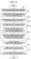
- An example of the map information on the first steering assist torque-1 is shown in FIG. 13 .
- the first steering assist torque-1 setter 33_2 calculates the first steering assist torque-1 corresponding to the corrected steering angle ⁇ h1.
- the map information on the first steering assist torque-1 (Ta1-1) is stored in the memory M in association with the vehicle speed, and the first steering assist torque-1 is set depending on the corrected steering angle and the vehicle speed.
- the three curves of FIG. 13 represent the first steering assist torques-1 corresponding to the steering angles of from zero to the reference steering angle for three kinds of vehicle speeds (the vehicle speed is lower in order from the bottom to the top), respectively.
- the first steering assist torque-1 has such characteristics that the steering assist torque-1 increases along with an increase in steering angle.
- the first steering assist torque-1 has such characteristics that the first steering assist torque-1 decreases along with an increase in vehicle speed.
- the first steering assist torque-1 may be set as a function instead of the map information.
- the second steering assist torque-1 setter 34_2 sets a second steering assist torque-1 (Ta1-2) corresponding to the corrected steering angle.
- information on the second steering assist torque-1 corresponding to steering angles of from zero to a reference steering angle is stored in the memory M in advance as map information.
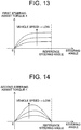
- map information on the second steering assist torque-1 is shown in FIG. 14 .
- the second steering assist torque-1 setter 34_2 calculates the second steering assist torque-1 corresponding to the corrected steering angle ⁇ h1.
- the map information on the second steering assist torque-1 (Ta1-2) is stored in the memory M in association with the vehicle speed, and the second steering assist torque-1 is set depending on the corrected steering angle and the vehicle speed.
- the three curves of FIG. 14 represent the second steering assist torques-1 corresponding to the steering angles of from zero to the reference steering angle for three kinds of vehicle speeds (the vehicle speed is lower in order from the bottom to the top), respectively.
- the second steering assist torque-1 has such characteristics that the second steering assist torque-1 decreases along with an increase in vehicle speed. Further, the second steering assist torque-1 has such characteristics that, under the same vehicle speed, the second steering assist torque-1 first increases along with an increase in steering angle but subsequently decreases after reaching the maximum steering assist torque.
- the second steering assist torque-1 may be set as a function instead of the map information.
- Step S22, Step S23_2, and Step S24_2 the steering angle to be input to the map is corrected, but as an alternative to this processing, instead of the steering angle, preset steering angles on the horizontal axis in the map information, that is, steering angles of from zero to the reference steering angle may be corrected.
- Step S25_2 the weighting device 35 follows Step S25 according to the above-mentioned embodiment to weight the first steering assist torque-1 (Ta1-1) and the second steering assist torque-1 (Ta1-2) based on the absolute value
- Step S26_2 the gain corrector 36 follows Step S26 according to the above-mentioned embodiment to set a correction gain based on the absolute value
- Step S27_2 the sign corrector 37 follows Step S27 according to the above-mentioned embodiment to set the sign of the fourth steering assist torque-1 (Ta1-4) based on the sign of the steering angle ⁇ h, to thereby obtain a fifth steering assist torque-1 (Ta1-5).
- the fifth steering assist torque-1 (Ta1-5) serves as the steering assist torque-1 (Ta1).
- the target steering speed is used for the purpose of appropriately returning the steering wheel to a neutral position when the driver releases the steering wheel 1 from his/her hand or returns the steering wheel 1, and hence the sign of the steering assist torque-1 is set to be opposite to the sign of the steering angle.
- Step S30 the steering assist torque-2 calculator 40 follows Step S30 according to the above-mentioned embodiment to calculate, in accordance with the assist map of FIG. 10 , for example, the steering assist torque-2 (Ta2) that is based at least on the steering torque from the torque sensor 5.
- Step S31 the adder 41 adds the fifth steering assist torque-1 (Ta1) and the steering assist torque-2 (Ta2) together, to thereby finally calculate the steering assist torque to be generated by the motor 6.
- Step S4 the steering assist torque calculator 24 finally calculates in Step S4 the steering assist torque to be generated by the motor 6, in Step S5, the current driver 12 of FIG. 2 drives the current of the motor 6 so that the motor 6 generates the steering assist torque.
- the first steering assist torque-1 and the second steering assist torque-1 are set by a corresponding method.
- the third to fifth steering assist torques-1 corresponding to the third to fifth target steering speeds, respectively, are set by a corresponding method.
- the fifth steering assist torque-1 serves as the steering assist torque-1 (Ta1) according to the first embodiment, and is added with the steering assist torque-2 (Ta2) to calculate the steering assist torque to be generated by the motor 6.
- Step S28 and Step S29 are unnecessary, and the calculation load on the CPU can be reduced.
- the same effects as those in the first embodiment can also be obtained.
- the weighting device 35 is configured to weight the first steering assist torque-1 (Ta1-1) and the second steering assist torque-1 (Ta1-2) based on the absolute value of the steering-holding determination steering angle, to thereby calculate the third steering assist torque-1 (Ta1-3), and hence an appropriate steering assist torque-1 can be set depending on the turning state at the time of the return steering.
- the target steering speed is not zero when the driver releases the steering wheel from his/her hand, and hence the steering wheel 1 can be returned to the neutral position even in a region in which the road surface reaction torque is so small that the steering wheel 1 cannot be returned to the neutral position.
- the gradient in the assist map shown in FIG. 10 is small and the steering assist torque-2 (Ta2) is small in this region, and hence the steering assist torque-1 (Ta1) as the fifth steering assist torque-1 set by the first steering assist torque-1 (Ta1-1) is more easily transmitted to the driver.
- the first steering assist torque-1 (Ta1-1) has such characteristics that the first steering assist torque-1 (Ta1-1) increases along with an increase in steering angle, and hence the driver's steering torque smoothly decreases as the steering angle becomes smaller, and an appropriate steering feeling can be realized.
- the steering assist torque-1 can be set to be zero or almost zero when the driver releases the steering wheel from his/her hand, and hence in a situation in which the road surface reaction torque is large and the return speed is high, it is possible to suppress an abrupt increase in return speed at the release of the steering wheel from the driver's hand.
- the steering assist torque-1 is set to be almost zero when the steering is held in a region in which the steering angle is large.
- the steering assist torque-1 is set to be almost zero.
- the target steering speed increases gradually from almost zero, and hence an abrupt increase in return torque can be prevented to realize a smooth change in steering torque, to thereby acquire an appropriate steering feeling.
- the weighting is performed by W1, and hence even when the steering wheel is returned from an intermediate steering angle between the steering angles described above, an appropriate steering assist torque-1 can be set.
- an appropriate steering assist torque can be set in every steering region.
- the gain corrector 36 is configured to set the correction gain W2 based on the absolute value of the steering-holding determination steering angle, and correct the third steering assist torque-1 (Ta1-3) based on the correction gain, to thereby calculate the fourth steering assist torque-1 (Ta1-4), and hence the magnitude of the steering assist torque-1 can be adjusted depending on a steering angle at which the driver releases the steering wheel from his/her hand.
- time until the steering wheel returns to the neutral position can be adjusted depending on the steering angle at which the driver releases the steering wheel from his/her hand, and, for example, when the time until the steering wheel returns to the neutral position is set substantially equal between the release from the driver's hand at a large steering angle and the release from the driver's hand at a small steering angle, an appropriate return of the steering wheel 1 can be realized.
- an appropriate steering assist torque can be acquired irrespective of the position of the steering wheel at the time when the driver turns back the steering wheel or releases the steering wheel from his/her hand, and therefore an appropriate return of the steering wheel and an appropriate steering feeling can be realized.
- the first steering assist torque-1 setter 33_2 and the second steering assist torque-1 setter 34_2 are configured to set the steering assist torque-1 corresponding to the corrected steering angle ⁇ h1 that is corrected by the state amount corrector 32 based on the magnitude of the steering-holding determination steering angle, and hence the amount of memory for the information on the steering assist torque-1 can be significantly reduced. If this system is not used, it is necessary to prepare the information on the steering assist torque-1 corresponding to each magnitude of the steering-holding determination steering angle or set a function corresponding thereto, with the result that the amount of memory is increased.
- the steering-holding determination device 22 is configured to update the steering-holding determination steering angle to the second stored value as zero and store the second stored value when the steering angle is almost zero, namely when the steering angle is equal to or smaller than the predetermined zero-determination threshold with which the steering angle is determinable to be almost zero, even in a situation in which the steering speed is larger than the steering speed threshold.
- the steering-holding determination steering angle can be set to be zero, and the steering assist torque-1 can be set to be zero. Consequently, the steering assist torque-1 can be prevented from being set larger than zero at the time of additional steering, thereby being capable of suppressing an increase in driver's steering torque.
- the steering angle sensor 4 is used as the vehicle turning state detector 21, and the steering angle sensor 4 is used also as an input signal used in the steering assist torque calculator 24, but another state amount representing the turning state of the vehicle may be used instead of the steering angle sensor 4.
- a yaw rate detected by a yaw rate sensor mounted to the vehicle is used as an input signal used in the vehicle turning state detector 21 and the steering assist torque calculator 24.
- the steering assist torque for returning the steering wheel 1 can be appropriately adjusted depending on a yaw rate at the start of the return of the steering wheel 1 or a yaw rate at the start of the release of the steering wheel 1 from the driver's hand, and therefore an appropriate return of the steering wheel and an appropriate steering feeling can be realized.
- the steering assist torque for returning the steering wheel may be generated because an offset amount of the steering angle is generated due to straight travel, when the yaw rate is used, the yaw rate is near zero, and hence the steering assist torque for returning the steering wheel is not generated. Consequently, there is an effect that the driver's steering torque can be prevented from fluctuating and an appropriate steering feeling can be realized.
- a lateral acceleration of the vehicle instead of the steering angle sensor 4, a lateral acceleration of the vehicle, a road surface reaction torque acting on the right and left steered wheels 3, or a steering torque may be used.
- the steering assist torque for returning the steering wheel 1 can be appropriately adjusted depending on the lateral acceleration, the road surface reaction torque, or the steering torque at the start of the return of the steering wheel or the start of the release of the steering wheel from the driver's hand, and therefore an appropriate return of the steering wheel and an appropriate steering feeling can be realized.
- the lateral acceleration, the road surface reaction torque, and the steering torque are the state amounts relating to the torque for returning the steering wheel 1 to a neutral position.
- the steering assist torque for returning the steering wheel 1 can be set small.
- the steering assist torque for returning the steering wheel 1 can be set large. Consequently, an appropriate steering assist torque can be acquired irrespective of the position of the steering wheel at the time when the driver turns back the steering wheel or releases the steering wheel from his/her hand, and therefore an appropriate return of the steering wheel and an appropriate steering feeling can be realized.
- the yaw rate and the lateral acceleration of the vehicle, the road surface reaction torque acting on the right and left steered wheels 3, and the steering torque are state amounts representing the turning state of the vehicle similarly to the steering angle, but have such characteristics that change amounts thereof decrease along with an increase in sideslip angle of the steered wheels. Accordingly, when the vehicle travels on a slippery road surface, if the sideslip angle increases so that the vehicle becomes unstable, the change amounts of those state amounts become smaller. Accordingly, when the vehicle travels on a slippery road surface, if the sideslip angle increases, the steering-holding determination state amount is set smaller so that the proportion of the first steering assist torque-1 to the steering assist torque-1 becomes higher as compared to when the vehicle stably travels with a small sideslip angle.
- the steering assist torque-1 for returning the steering wheel 1 to a neutral point is generated at the start of the return of the steering wheel 1 or the start of the release of the steering wheel 1 from the driver's hand, and hence there is an effect of facilitating the steering operation of returning the steering wheel 1 to the neutral point for stabilizing the vehicle.
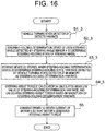
- FIG. 15 A block diagram of a control unit, which is a main part of a steering control device, according to a third embodiment of the present invention is illustrated in FIG. 15 , and an operation flowchart of the control unit is illustrated in FIG. 16 .
- the other parts are basically the same as those in the above-mentioned embodiments.
- this embodiment as compared to the first embodiment, another state amount representing a turning state of the vehicle is used as the vehicle turning state detector 21 instead of the steering angle sensor 4.
- the vehicle turning state detector 21 includes a yaw rate sensor 4c, and the steering angle sensor 4 is separately mounted.
- Step S1_3 the yaw rate sensor 4c is used as the vehicle turning state detector 21 to detect a yaw rate.
- the yaw rate is used as a state amount representing a turning state of the vehicle.
- the steering-holding determination device 22 determines a steering-holding state of a steering system of the vehicle, that is, whether or not the steering wheel 1 remains at a substantially constant steering angle. In the steering-holding determination, the steering-holding determination device 22 uses the steering angle detected by the steering angle sensor 4 to calculate a steering speed based on the steering angle, and determines a situation in which the magnitude of the steering speed is smaller than a predetermined steering speed threshold as the steering-holding state.
- Step S3_3 the storing device 23 stores a value detected by the vehicle turning state detector 21 at the time when the steering-holding determination device 22 determines that the steering system is in the steering-holding state in the memory M as a steering-holding determination state amount.
- the storing device 23 stores the yaw rate, at the time when the steering-holding determination device 22 determines that the steering system is in the steering-holding state, in the memory M as a steering-holding determination yaw rate.
- Step S4_3 the steering assist torque calculator 24 calculates the magnitude of the steering-holding determination state amount, that is, an absolute value of the steering-holding determination yaw rate, and calculates a steering assist torque based on the absolute value of the steering-hoiding determination yaw rate.
- FIG. 17 A block diagram of the steering assist torque calculator 24 is illustrated in FIG. 17 .
- the steering state detector (vehicle turning state detector) 21 is the yaw rate sensor (not shown in FIG. 17 ) and that a vehicle speed is used in the state amount corrector 32.
- a steering angle is used as an input signal used in the steering assist torque calculator 24.
- the state amount corrector 32 corrects the steering angle ⁇ h based on the absolute value
- the steering-holding determination state amount is the yaw rate unlike the first embodiment, based on the vehicle speed and the steering-holding determination yaw rate, a steering angle corresponding to the steering-holding determination yaw rate is calculated, and the calculated steering angle is determined as the steering-holding determination steering angle. Consequently, the steering angle used in the first target steering speed setter 33 and the second target steering speed setter 34 can be corrected by using Expression (1). In other words, the corrected steering angle ⁇ h1 is acquired.
- the yaw rate sensor 4c representing the turning state of the vehicle is used instead of the steering angle sensor 4.
- the other parts are basically the same. Note that, the use of the yaw rate sensor 4c is applicable also to the other embodiments.
- the effects described in the first embodiment can be obtained. Further, in the case where the vehicle travels straight forward on a traveling road surface having a cross slope, when the yaw rate is used, the yaw rate is near zero and the steering-holding determination yaw rate is not offset, and hence the correction gain W2 set by the gain corrector 36 is small, and the steering assist torque for returning the steering wheel is not generated. Consequently, there is an effect that the driver's steering torque can be prevented from fluctuating and an appropriate steering feeling can be realized.
- the yaw rate sensor 4c is used as the vehicle turning state detector 21, but the present invention is not limited thereto.
- Another state amount representing the turning state of the vehicle can be used.
- a lateral acceleration of the vehicle, a road surface reaction torque acting on the right and left steered wheels 3, or a steering torque may be used.
- the steering assist torque for returning the steering wheel 1 can be appropriately adjusted depending on the turning state of the vehicle such as the lateral acceleration, the road surface reaction torque, or the steering torque, and therefore an appropriate return of the steering wheel and an appropriate steering feeling can be realized.
- the lateral acceleration, the road surface reaction torque, and the steering torque are state amounts relating to the torque for returning the steering wheel 1 to a neutral position.
- the steering assist torque for returning the steering wheel 1 can be set small.
- the steering assist torque for returning the steering wheel 1 can be set large. Consequently, an appropriate steering assist torque can be acquired irrespective of the position of the steering wheel at the time when the driver turns back the steering wheel or releases the steering wheel from his/her hand, and therefore an appropriate return of the steering wheel and an appropriate steering feeling can be realized.
- the yaw rate and the lateral acceleration of the vehicle, the road surface reaction torque acting on the right and left steered wheels 3, and the steering torque are the state amounts representing the turning state of the vehicle similarly to the steering angle, but have such characteristics that change amounts thereof decrease along with an increase in sideslip angle of the steered wheels. Accordingly, when the vehicle travels on a slippery road surface, if the sideslip angle increases so that the vehicle becomes unstable, the change amounts of those state amounts become smaller. Accordingly, when the vehicle travels on a slippery road surface, if the sideslip angle increases, the steering-holding determination state amount is set smaller so that the proportion of the first steering assist torque-1 to the steering assist torque-1 becomes higher as compared to when the vehicle stably travels with a small sideslip angle.
- the steering assist torque-1 for returning the steering wheel 1 to a neutral point is generated at the start of the return of the steering wheel 1 or the start of the release of the steering wheel 1 from the driver's hand, and hence there is an effect of facilitating the steering operation of returning the steering wheel 1 to the neutral point for stabilizing the vehicle.
- this embodiment has been described for the differences from the first embodiment, but it should be understood that this embodiment can be combined with the second embodiment so that another state amount representing the turning state of the vehicle, such as the yaw rate sensor, is used as the steering state detector (vehicle turning state detector) 21.
- a plurality of state amounts each representing the turning state of the vehicle may be used.
- the yaw rate has such characteristics that a change amount thereof decreases along with an increase in sideslip angle of the steered wheels. Accordingly, when the vehicle travels on a slippery road surface, if the sideslip angle increases so that the change amount of the yaw rate decreases, the relationship between the steering-holding determination steering angle and the steering-holding determination yaw rate changes, that is, the ratio of the steering-holding determination yaw rate to the steering-holding determination steering angle becomes smaller as the sideslip angle becomes larger.
- FIG. 18 A block diagram of a steering assist torque calculator according to a fourth embodiment of the present invention is illustrated in FIG. 18 , and an operation flowchart of the steering assist torque calculator is illustrated in FIG. 19 .
- the other parts are basically the same as those in the above-mentioned embodiments.
- the steering assist torque calculator 24 corrects a steering assist torque-2 based on the magnitude of a steering-holding determination state amount.
- the steering angle sensor 4 (see FIG. 2 ) is used as the vehicle turning state detector 21 to detect a steering angle.
- the steering angle is used as a state amount representing a turning state of the vehicle.
- the steering assist torque calculator 24 of FIG. 18 calculates the magnitude of the steering-holding determination state amount, that is, an absolute value of the steering-holding determination steering angle, and calculates the steering assist torque based on the absolute value of the steering-hoiding determination steering angle.
- An operation flowchart of the steering assist torque calculator 24 is illustrated in FIG. 19 .
- the steering assist torque calculator 24 uses a steering torque as an input signal.
- Step S21 of FIG. 19 the absolute value calculator 31 calculates an absolute value
- a steering assist torque-3 calculator 42 calculates the steering assist torque-2 that is based at least on the steering torque. For example, the vehicle speed and the steering assist torque-2 with respect to the steering torque as shown in the assist map of FIG. 10 are stored in the memory M in advance, and the steering assist torque-2 is set depending on the steering torque and the vehicle speed.
- Step S31_4 the steering assist torque-3 calculator 42 sets a correction gain W2 based on the absolute value
- the steering assist torque calculator 24 sets the correction gain W2 based on the absolute value
- the steering assist torque-2 is set depending on the steering torque by using the assist map shown in FIG. 10 , and accordingly serves as a steering assist torque for reducing the driver's steering torque.
- the steering-holding determination steering angle is near zero, and hence the correction gain W2 is almost zero.
- the same steering assist torque-2 as that in the related art is calculated as the steering assist torque.
- the steering-holding determination steering angle of other than zero is set, and the correction gain W2 of other than zero is set.
- the steering assist torque-2 larger than that in the related art is calculated as the steering assist torque. Consequently, the steering assist torque when the steering wheel is returned can be changed with respect to that when the steering wheel is additionally turned. Further, an appropriate steering assist torque can be acquired for a steering angle at which the driver turns back the steering wheel 1 or a steering angle at which the driver releases the steering wheel 1 from his/her hand, and therefore an appropriate return of the steering wheel and an appropriate steering feeling can be realized.
- the steering assist torque-3 calculator 42 is configured to calculate the steering assist torque-2 that is based on the steering torque, but the present invention is not limited thereto.
- a steering assist torque calculated by a related-art steering control device may be corrected based on the magnitude (absolute value) of the steering-holding determination steering angle.
- the steering assist torque calculated by the related-art steering control device may be appropriately set for a steering angle at which the driver turns back the steering wheel 1 or a steering angle at which the driver releases the steering wheel 1 from his/her hand, and therefore an appropriate steering feeling can be realized.
- the steering angle is used as the steering-holding determination state amount, but the present invention is not limited thereto.
- Another state amount representing the turning state of the vehicle may be used instead of the steering angle.
- the correction gain W2 is set depending on a steering-holding determination road surface reaction torque.
- the steering assist torque can be appropriately set depending on a road surface reaction torque at the start of the return of the steering wheel or a road surface reaction torque at the start of the release of the steering wheel from the driver's hand, and therefore an appropriate return of the steering wheel and an appropriate steering feeling can be realized.
- the road surface reaction torque has such characteristics that a change amount thereof is saturated along with an increase in sideslip angle of the steered wheels. Accordingly, when the vehicle travels on a slippery road surface, if the sideslip angle increases so that the road surface reaction torque is saturated, the correction gain W2 is set small, and hence the steering assist torque-2 can be prevented from being set excessively large.
- only one target steering speed setter or only one steering assist torque-1 setter may be mounted, and the weighting device 35 may be omitted.
- the range of adjusting the steering assist torque is limited, but the calculation load can be reduced, and the magnitude of the steering assist torque can be adjusted depending on the steering-holding determination state
- three or more target steering speed setters or three or more steering assist torque-1 setters may be mounted.
- the steering assist torque can be more finely adjusted depending on the position of the steering wheel at the time when the driver turns back the steering wheel or releases the steering wheel from his/her hand, and therefore an appropriate return of the steering wheel and an appropriate steering feeling can be realized.
- the motor 6 and the speed reduction mechanism 7 serve as an actuator
- the vehicle turning state detector 21 serves as a vehicle turning state detection section
- the steering-holding determination device 22 serves as a steering-holding determination section
- the storing device 23 and the memory M serve as a storing section
- the steering assist torque calculator 24 serves as a steering assist torque calculation section
- the vehicle speed sensor 8 serves as a vehicle speed detection section
- the current driver 12 serves as an actuator control section.
- the first steering assist torque setting information includes the first target steering speed or the first steering assist torque
- the second steering assist torque setting information includes the second target steering speed or the second steering assist torque
- the reference steering assist torque includes the steering assist torque-2.
- the first to fifth target steering speeds correspond to the target return speeds.
- the steering control device and the like according to the present invention are applicable to various kinds of steering devices, and similar effects are obtained.
Landscapes
- Engineering & Computer Science (AREA)
- Chemical & Material Sciences (AREA)
- Combustion & Propulsion (AREA)
- Transportation (AREA)
- Mechanical Engineering (AREA)
- Steering Control In Accordance With Driving Conditions (AREA)
- Power Steering Mechanism (AREA)
Claims (12)
- Dispositif de commande de direction pour fournir un couple d'assistance de direction lorsqu'un système de direction d'un véhicule retourne à une position neutre, comprenant:un actionneur (6, 7) pour appliquer un couple d'assistance de direction au système de direction ; etune section de détection d'état de virage de véhicule (21) pour détecter une grandeur d'état représentant un état de virage du véhicule ;caractérisé en ce que le dispositif de commande de direction comprend :une section de détermination de maintien de direction (22) pour la détermination d'un état de maintien de direction du système de direction ;une section de stockage (23) pour stocker, lorsque la section de détermination de maintien de direction détermine que le système de direction est dans un état de maintien de direction, la grandeur d'état détectée par la section de détection d'état de virage de véhicule en tant que grandeur d'état de détermination de maintien de direction ;une section de calcul de couple d'assistance de direction (24) pour calculer le couple d'assistance de direction sur la base d'une valeur absolue de la grandeur d'état de détermination de maintien de direction ; etune section de commande d'actionneur (12) pour commander l'actionneur sur la base du couple d'assistance de direction calculé.
- Dispositif de commande de direction selon la revendication 1, dans lequel la section de calcul de couple d'assistance de direction (24) corrige un signal d'entrée sur la base d'une amplitude de la grandeur d'état de détermination de maintien de direction, et calcule le couple d'assistance de direction sur la base du signal d'entrée corrigé.
- Dispositif de commande de direction selon la revendication 1 ou 2, dans lequel la section de calcul de couple d'assistance de direction (24) stocke à l'avance au moins des premières informations de réglage de couple d'assistance de direction, qui concernent le couple d'assistance de direction lorsqu'un angle de direction au moment de la détermination de maintien de direction est petit, et des secondes informations de réglage de couple d'assistance de direction, qui concernent le couple d'assistance de direction lorsque l'angle de direction au moment de la détermination de maintien de direction est grand, et les premières informations de réglage de couple d'assistance de direction ou les secondes informations de réglage de couple d'assistance de direction sont sélectionnées ou pondérées selon la grandeur d'état de détermination de maintien de direction, pour calculer par là même le couple d'assistance de direction.
- Dispositif de commande de direction selon l'une quelconque des revendications 1 à 3, dans lequel même lorsque la section de détermination de maintien de direction ne détermine pas que le système de direction est dans l'état de maintien de direction, la section de stockage (23) met à jour la grandeur d'état de détermination de maintien de direction à une valeur prédéterminée lorsqu'un angle de direction est égal ou inférieur à un seuil de détermination de zéro prédéterminé avec lequel l'angle de direction peut être déterminé comme étant presque à zéro.
- Dispositif de commande de direction selon l'une quelconque des revendications 1 à 4, comprenant en outre une section de détection de vitesse de véhicule (8) pour détecter une vitesse de véhicule du véhicule,
dans lequel la section de calcul de couple d'assistance de direction (24) calcule le couple d'assistance de direction sur la base de la vitesse de véhicule détectée par la section de détection de vitesse de véhicule. - Dispositif de commande de direction selon l'une quelconque des revendications 1 à 5, dans lequel la section de calcul de couple d'assistance de direction (24) limite une amplitude du couple d'assistance de direction comme étant égale ou inférieure à une valeur prédéterminée, qui est une amplitude telle qu'un conducteur est capable de diriger le système de direction tout en résistant au couple d'assistance de direction.
- Dispositif de commande de direction selon l'une quelconque des revendications 1 à 6, dans lequel la section de détection d'état de virage de véhicule (21) détecte un angle de direction du système de direction.
- Dispositif de commande de direction selon l'une quelconque des revendications 1 à 6, dans lequel la section de détection d'état de virage de véhicule (21) détecte au moins l'un d'un couple de direction du système de direction, d'une accélération latérale du véhicule ou d'un couple de réaction de surface de route du véhicule.
- Dispositif de commande de direction selon l'une quelconque des revendications 1 à 6, dans lequel la section de détection d'état de virage de véhicule (21) détecte un taux de lacet du véhicule.
- Dispositif de commande de direction selon la revendication 7, dans lequel la section de calcul de couple d'assistance de direction (24) calcule une vitesse de retour cible correspondant à l'angle de direction, et calcule le couple d'assistance de direction de sorte qu'une vitesse de direction du système de direction suit la vitesse de retour cible calculée.
- Dispositif de commande de direction selon l'une quelconque des revendications 1 à 10, dans lequel la section de calcul de couple d'assistance de direction (24) calcule un couple d'assistance de direction de référence, qui est déterminé sur la base d'un couple de direction et d'une vitesse du véhicule, et sort le couple d'assistance de direction obtenu par correction du couple d'assistance de direction de référence avec le couple d'assistance de direction calculé.
- Procédé de commande de direction pour fournir un couple d'assistance de direction lorsqu'un système de direction d'un véhicule retourne à une position neutre, comprenant les étapes de :détection (21) d'une grandeur d'état représentant un état de virage du véhicule ;caractérisé par :la détermination (22) d'un état de maintien de direction du système de direction ;le stockage (23) de la grandeur d'état à un moment où le système de direction est déterminé comme étant dans l'état de maintien de direction, comme grandeur d'état de détermination de maintien de direction ;le calcul (24) d'un couple d'assistance de direction sur la base d'une valeur absolue de la grandeur d'état de détermination de maintien de direction ; etla commande (12) d'un actionneur de sorte que l'actionneur applique le couple d'assistance de direction calculé au système de direction du véhicule.
Applications Claiming Priority (1)
| Application Number | Priority Date | Filing Date | Title |
|---|---|---|---|
| PCT/JP2013/060634 WO2014167629A1 (fr) | 2013-04-08 | 2013-04-08 | Dispositif et procédé de commande de direction |
Publications (3)
| Publication Number | Publication Date |
|---|---|
| EP2985207A1 EP2985207A1 (fr) | 2016-02-17 |
| EP2985207A4 EP2985207A4 (fr) | 2017-01-11 |
| EP2985207B1 true EP2985207B1 (fr) | 2018-05-23 |
Family
ID=51689066
Family Applications (1)
| Application Number | Title | Priority Date | Filing Date |
|---|---|---|---|
| EP13882023.8A Not-in-force EP2985207B1 (fr) | 2013-04-08 | 2013-04-08 | Dispositif et procédé de commande de direction |
Country Status (5)
| Country | Link |
|---|---|
| US (1) | US9896122B2 (fr) |
| EP (1) | EP2985207B1 (fr) |
| JP (1) | JP5951116B2 (fr) |
| CN (1) | CN105102301B (fr) |
| WO (1) | WO2014167629A1 (fr) |
Families Citing this family (18)
| Publication number | Priority date | Publication date | Assignee | Title |
|---|---|---|---|---|
| JP6260818B2 (ja) * | 2014-02-18 | 2018-01-17 | 株式会社ジェイテクト | 電動パワーステアリング装置 |
| JP6323395B2 (ja) * | 2015-05-29 | 2018-05-16 | トヨタ自動車株式会社 | 電動パワーステアリング装置 |
| JP2017039466A (ja) * | 2015-08-21 | 2017-02-23 | 株式会社東海理化電機製作所 | 車両用操作装置 |
| KR102350043B1 (ko) * | 2015-11-20 | 2022-01-12 | 주식회사 만도 | 자동 조향 제어 시스템 및 방법 |
| JP6352956B2 (ja) * | 2016-01-26 | 2018-07-04 | 株式会社Subaru | 車両の制御装置及び車両の制御方法 |
| US9969426B2 (en) * | 2016-06-01 | 2018-05-15 | GM Global Technology Operations LLC | Systems and methods for variable steering assist-II |
| JP2018069998A (ja) * | 2016-10-31 | 2018-05-10 | 株式会社ジェイテクト | 車両用姿勢制御装置 |
| JP6873362B2 (ja) * | 2016-12-16 | 2021-05-19 | 日立Astemo株式会社 | 電動パワーステアリング装置 |
| US20180222518A1 (en) * | 2017-02-08 | 2018-08-09 | Peter Joseph Hill | Curve and terrain responsive steering system |
| US10569651B2 (en) * | 2017-05-15 | 2020-02-25 | Baidu Usa Llc | Speed control and steering control assistant based on pitch status and roll status of autonomous driving vehicle |
| CN107128354B (zh) * | 2017-05-19 | 2019-06-18 | 北京新能源汽车股份有限公司 | 一种转向控制方法、装置及汽车 |
| CN110758548B (zh) * | 2018-07-27 | 2021-06-18 | 比亚迪股份有限公司 | 转向助力控制方法、车辆、服务器、存储介质及系统 |
| KR102621533B1 (ko) * | 2018-11-26 | 2024-01-05 | 현대자동차주식회사 | 차량 조향 시스템의 제어 장치 및 제어 방법 |
| WO2020130479A1 (fr) * | 2018-12-19 | 2020-06-25 | 주식회사 만도 | Appareil de commande de direction, procédé de commande de direction et dispositif de direction |
| CN113474236B (zh) * | 2019-02-19 | 2024-01-12 | 日本精工株式会社 | 车辆用转向装置 |
| JP7197413B2 (ja) * | 2019-03-25 | 2022-12-27 | トヨタ自動車株式会社 | 操舵制御システム |
| DE102019206980B4 (de) * | 2019-05-14 | 2023-06-22 | Volkswagen Aktiengesellschaft | Verfahren und Lenkungssteuergerät zum Ermitteln einer Stellgröße für das Einstellen eines Servolenkmoments bei einem Fahrzeuglenksystem |
| JP2021011190A (ja) * | 2019-07-05 | 2021-02-04 | 株式会社Subaru | 車両の操舵支援装置 |
Family Cites Families (35)
| Publication number | Priority date | Publication date | Assignee | Title |
|---|---|---|---|---|
| JP3555126B2 (ja) | 1997-03-25 | 2004-08-18 | トヨタ自動車株式会社 | 操舵制御装置 |
| JP3314866B2 (ja) * | 1997-09-13 | 2002-08-19 | 本田技研工業株式会社 | 車両用操舵装置 |
| JPH11198844A (ja) * | 1998-01-19 | 1999-07-27 | Nissan Motor Co Ltd | 操舵力制御装置 |
| JP4231910B2 (ja) * | 2000-04-25 | 2009-03-04 | 日産自動車株式会社 | 車線維持装置 |
| US6736604B2 (en) * | 2001-06-18 | 2004-05-18 | Unisia Jkc Steering Systems Co., Ltd. | Control apparatus of variable displacement pump for power steering apparatus |
| US6695092B2 (en) * | 2002-03-04 | 2004-02-24 | Delphi Technologies, Inc. | Steering actuator system |
| JP3960266B2 (ja) * | 2003-05-28 | 2007-08-15 | トヨタ自動車株式会社 | 車輌用操舵制御装置 |
| JP2005041283A (ja) * | 2003-07-24 | 2005-02-17 | Hitachi Unisia Automotive Ltd | 操舵制御装置 |
| JP4411514B2 (ja) * | 2003-09-08 | 2010-02-10 | 株式会社ジェイテクト | 電動パワーステアリング装置 |
| US6970777B2 (en) * | 2003-11-26 | 2005-11-29 | Nissan Motor Co., Ltd. | Automotive lane deviation prevention apparatus |
| JP3966274B2 (ja) | 2003-12-04 | 2007-08-29 | トヨタ自動車株式会社 | 操舵制御装置 |
| JP4304604B2 (ja) * | 2004-02-16 | 2009-07-29 | 株式会社デンソー | 車両の電動パワーステアリング装置 |
| JP3889758B2 (ja) * | 2004-09-10 | 2007-03-07 | 三菱電機株式会社 | ステアリング制御装置 |
| JP4349309B2 (ja) * | 2004-09-27 | 2009-10-21 | 日産自動車株式会社 | 車両用操舵制御装置 |
| JP4715446B2 (ja) | 2005-10-31 | 2011-07-06 | 日本精工株式会社 | 電動パワーステアリング装置の制御装置 |
| EP2256019B1 (fr) * | 2005-01-14 | 2013-06-05 | NSK Ltd. | Appareil de commande de direction assistée électrique |
| JP4725132B2 (ja) * | 2005-03-01 | 2011-07-13 | 日産自動車株式会社 | 操舵制御装置 |
| JP5011757B2 (ja) * | 2005-08-02 | 2012-08-29 | 日産自動車株式会社 | 車両用操舵装置 |
| JP4876634B2 (ja) * | 2006-03-01 | 2012-02-15 | 日産自動車株式会社 | 車両用操舵制御装置 |
| JP4853053B2 (ja) * | 2006-03-03 | 2012-01-11 | 日産自動車株式会社 | 車両用操舵制御装置 |
| US7363135B2 (en) * | 2006-06-27 | 2008-04-22 | Gm Global Technology Operations, Inc. | Steering haptic feedback system for vehicle active safety |
| JP4287452B2 (ja) * | 2006-09-12 | 2009-07-01 | 本田技研工業株式会社 | 車両の自動操舵装置 |
| JP4997472B2 (ja) * | 2007-01-09 | 2012-08-08 | 株式会社ジェイテクト | 電動パワーステアリング装置 |
| JP4420036B2 (ja) * | 2007-02-05 | 2010-02-24 | 日産自動車株式会社 | 車両用操舵制御装置 |
| EP2017162B1 (fr) * | 2007-07-19 | 2013-06-12 | Nissan Motor Co., Ltd. | Système d'assistance de conduite sur voie, procédé d'assistance de conduite sur voie et automobile |
| EP2020361B1 (fr) * | 2007-08-02 | 2012-06-27 | Nissan Motor Co., Ltd. | Appareil contrôle de direction de véhicule |
| JP2009061878A (ja) * | 2007-09-05 | 2009-03-26 | Toyota Motor Corp | 走行制御装置 |
| JP5012925B2 (ja) * | 2010-02-08 | 2012-08-29 | 株式会社デンソー | 車両用運動制御装置 |
| JP5221600B2 (ja) * | 2010-06-30 | 2013-06-26 | トヨタ自動車株式会社 | 車両用操舵装置 |
| CN103228522B (zh) * | 2010-11-29 | 2016-05-25 | 日产自动车株式会社 | 车辆及其转向操纵控制方法 |
| JP2012166769A (ja) | 2011-02-17 | 2012-09-06 | Jtekt Corp | 電動パワーステアリング装置 |
| JP5316599B2 (ja) | 2011-07-05 | 2013-10-16 | トヨタ自動車株式会社 | 操舵装置及び操舵制御装置 |
| WO2013114429A1 (fr) * | 2012-01-31 | 2013-08-08 | トヨタ自動車株式会社 | Dispositif de commande de direction de véhicule |
| JP5620951B2 (ja) * | 2012-07-27 | 2014-11-05 | 富士重工業株式会社 | 車両のパワーステアリング制御装置 |
| CN104995079B (zh) * | 2013-01-11 | 2017-03-22 | 日产自动车株式会社 | 转向控制装置、转向控制方法 |
-
2013
- 2013-04-08 CN CN201380075403.6A patent/CN105102301B/zh not_active Expired - Fee Related
- 2013-04-08 US US14/768,096 patent/US9896122B2/en active Active
- 2013-04-08 WO PCT/JP2013/060634 patent/WO2014167629A1/fr active Application Filing
- 2013-04-08 JP JP2015510976A patent/JP5951116B2/ja not_active Expired - Fee Related
- 2013-04-08 EP EP13882023.8A patent/EP2985207B1/fr not_active Not-in-force
Non-Patent Citations (1)
| Title |
|---|
| None * |
Also Published As
| Publication number | Publication date |
|---|---|
| JPWO2014167629A1 (ja) | 2017-02-16 |
| EP2985207A1 (fr) | 2016-02-17 |
| US20150375777A1 (en) | 2015-12-31 |
| CN105102301B (zh) | 2017-09-22 |
| EP2985207A4 (fr) | 2017-01-11 |
| JP5951116B2 (ja) | 2016-07-13 |
| CN105102301A (zh) | 2015-11-25 |
| US9896122B2 (en) | 2018-02-20 |
| WO2014167629A1 (fr) | 2014-10-16 |
Similar Documents
| Publication | Publication Date | Title |
|---|---|---|
| EP2985207B1 (fr) | Dispositif et procédé de commande de direction | |
| EP2985205B1 (fr) | Dispositif et procédé de commande de direction | |
| JP4341665B2 (ja) | 車両操舵制御装置 | |
| US9738307B2 (en) | Steering control device, and steering control method | |
| JP5109342B2 (ja) | 電動パワーステアリング装置 | |
| US9821837B2 (en) | Electric power steering apparatus | |
| US20150191199A1 (en) | Electric power steering apparatus | |
| JP5233624B2 (ja) | 車両用操舵制御装置および方法 | |
| JPWO2010109676A1 (ja) | 車両の操舵装置 | |
| CN109383617B (zh) | 电动助力转向设备及其控制方法 | |
| CN107792165A (zh) | 转向控制装置 | |
| JP5028960B2 (ja) | 電動パワーステアリング装置 | |
| EP2700564B1 (fr) | Appareil de direction assistée électrique | |
| JP5206170B2 (ja) | 車両用操舵制御装置及び方法 | |
| JP2011051409A (ja) | 電動パワーステアリング装置 | |
| US11891136B2 (en) | Steering control device | |
| JP2008149887A (ja) | 電動パワーステアリング装置 | |
| JP6212987B2 (ja) | 操舵制御装置 | |
| KR100968066B1 (ko) | 능동 전륜 조향 시스템에서의 조향각 센서의 오프셋보상제어방법 | |
| JP5141059B2 (ja) | 電動パワーステアリング装置の制御装置 | |
| JP2008024073A (ja) | 電動パワーステアリング装置 | |
| JP2014080179A (ja) | 操舵制御装置 | |
| JP4840232B2 (ja) | 車両の操舵制御装置 | |
| JP5510504B2 (ja) | 電動パワーステアリング装置 | |
| JP6221416B2 (ja) | 操舵制御装置 |
Legal Events
| Date | Code | Title | Description |
|---|---|---|---|
| PUAI | Public reference made under article 153(3) epc to a published international application that has entered the european phase |
Free format text: ORIGINAL CODE: 0009012 |
|
| 17P | Request for examination filed |
Effective date: 20150909 |
|
| AK | Designated contracting states |
Kind code of ref document: A1 Designated state(s): AL AT BE BG CH CY CZ DE DK EE ES FI FR GB GR HR HU IE IS IT LI LT LU LV MC MK MT NL NO PL PT RO RS SE SI SK SM TR |
|
| AX | Request for extension of the european patent |
Extension state: BA ME |
|
| DAX | Request for extension of the european patent (deleted) | ||
| A4 | Supplementary search report drawn up and despatched |
Effective date: 20161213 |
|
| RIC1 | Information provided on ipc code assigned before grant |
Ipc: B62D 119/00 20060101ALI20161207BHEP Ipc: B62D 113/00 20060101ALI20161207BHEP Ipc: B62D 5/04 20060101ALI20161207BHEP Ipc: B62D 6/00 20060101AFI20161207BHEP |
|
| GRAP | Despatch of communication of intention to grant a patent |
Free format text: ORIGINAL CODE: EPIDOSNIGR1 |
|
| STAA | Information on the status of an ep patent application or granted ep patent |
Free format text: STATUS: GRANT OF PATENT IS INTENDED |
|
| INTG | Intention to grant announced |
Effective date: 20171120 |
|
| GRAJ | Information related to disapproval of communication of intention to grant by the applicant or resumption of examination proceedings by the epo deleted |
Free format text: ORIGINAL CODE: EPIDOSDIGR1 |
|
| STAA | Information on the status of an ep patent application or granted ep patent |
Free format text: STATUS: REQUEST FOR EXAMINATION WAS MADE |
|
| GRAR | Information related to intention to grant a patent recorded |
Free format text: ORIGINAL CODE: EPIDOSNIGR71 |
|
| GRAS | Grant fee paid |
Free format text: ORIGINAL CODE: EPIDOSNIGR3 |
|
| STAA | Information on the status of an ep patent application or granted ep patent |
Free format text: STATUS: GRANT OF PATENT IS INTENDED |
|
| INTC | Intention to grant announced (deleted) | ||
| INTG | Intention to grant announced |
Effective date: 20180314 |
|
| GRAA | (expected) grant |
Free format text: ORIGINAL CODE: 0009210 |
|
| STAA | Information on the status of an ep patent application or granted ep patent |
Free format text: STATUS: THE PATENT HAS BEEN GRANTED |
|
| AK | Designated contracting states |
Kind code of ref document: B1 Designated state(s): AL AT BE BG CH CY CZ DE DK EE ES FI FR GB GR HR HU IE IS IT LI LT LU LV MC MK MT NL NO PL PT RO RS SE SI SK SM TR |
|
| REG | Reference to a national code |
Ref country code: GB Ref legal event code: FG4D |
|
| REG | Reference to a national code |
Ref country code: CH Ref legal event code: EP |
|
| REG | Reference to a national code |
Ref country code: IE Ref legal event code: FG4D |
|
| REG | Reference to a national code |
Ref country code: AT Ref legal event code: REF Ref document number: 1001290 Country of ref document: AT Kind code of ref document: T Effective date: 20180615 |
|
| REG | Reference to a national code |
Ref country code: DE Ref legal event code: R096 Ref document number: 602013037971 Country of ref document: DE |
|
| REG | Reference to a national code |
Ref country code: NL Ref legal event code: MP Effective date: 20180523 |
|
| REG | Reference to a national code |
Ref country code: LT Ref legal event code: MG4D |
|
| PG25 | Lapsed in a contracting state [announced via postgrant information from national office to epo] |
Ref country code: SE Free format text: LAPSE BECAUSE OF FAILURE TO SUBMIT A TRANSLATION OF THE DESCRIPTION OR TO PAY THE FEE WITHIN THE PRESCRIBED TIME-LIMIT Effective date: 20180523 Ref country code: FI Free format text: LAPSE BECAUSE OF FAILURE TO SUBMIT A TRANSLATION OF THE DESCRIPTION OR TO PAY THE FEE WITHIN THE PRESCRIBED TIME-LIMIT Effective date: 20180523 Ref country code: BG Free format text: LAPSE BECAUSE OF FAILURE TO SUBMIT A TRANSLATION OF THE DESCRIPTION OR TO PAY THE FEE WITHIN THE PRESCRIBED TIME-LIMIT Effective date: 20180823 Ref country code: NO Free format text: LAPSE BECAUSE OF FAILURE TO SUBMIT A TRANSLATION OF THE DESCRIPTION OR TO PAY THE FEE WITHIN THE PRESCRIBED TIME-LIMIT Effective date: 20180823 Ref country code: ES Free format text: LAPSE BECAUSE OF FAILURE TO SUBMIT A TRANSLATION OF THE DESCRIPTION OR TO PAY THE FEE WITHIN THE PRESCRIBED TIME-LIMIT Effective date: 20180523 Ref country code: LT Free format text: LAPSE BECAUSE OF FAILURE TO SUBMIT A TRANSLATION OF THE DESCRIPTION OR TO PAY THE FEE WITHIN THE PRESCRIBED TIME-LIMIT Effective date: 20180523 |
|
| PG25 | Lapsed in a contracting state [announced via postgrant information from national office to epo] |
Ref country code: GR Free format text: LAPSE BECAUSE OF FAILURE TO SUBMIT A TRANSLATION OF THE DESCRIPTION OR TO PAY THE FEE WITHIN THE PRESCRIBED TIME-LIMIT Effective date: 20180824 Ref country code: HR Free format text: LAPSE BECAUSE OF FAILURE TO SUBMIT A TRANSLATION OF THE DESCRIPTION OR TO PAY THE FEE WITHIN THE PRESCRIBED TIME-LIMIT Effective date: 20180523 Ref country code: RS Free format text: LAPSE BECAUSE OF FAILURE TO SUBMIT A TRANSLATION OF THE DESCRIPTION OR TO PAY THE FEE WITHIN THE PRESCRIBED TIME-LIMIT Effective date: 20180523 Ref country code: LV Free format text: LAPSE BECAUSE OF FAILURE TO SUBMIT A TRANSLATION OF THE DESCRIPTION OR TO PAY THE FEE WITHIN THE PRESCRIBED TIME-LIMIT Effective date: 20180523 Ref country code: NL Free format text: LAPSE BECAUSE OF FAILURE TO SUBMIT A TRANSLATION OF THE DESCRIPTION OR TO PAY THE FEE WITHIN THE PRESCRIBED TIME-LIMIT Effective date: 20180523 |
|
| REG | Reference to a national code |
Ref country code: AT Ref legal event code: MK05 Ref document number: 1001290 Country of ref document: AT Kind code of ref document: T Effective date: 20180523 |
|
| PG25 | Lapsed in a contracting state [announced via postgrant information from national office to epo] |
Ref country code: AT Free format text: LAPSE BECAUSE OF FAILURE TO SUBMIT A TRANSLATION OF THE DESCRIPTION OR TO PAY THE FEE WITHIN THE PRESCRIBED TIME-LIMIT Effective date: 20180523 Ref country code: CZ Free format text: LAPSE BECAUSE OF FAILURE TO SUBMIT A TRANSLATION OF THE DESCRIPTION OR TO PAY THE FEE WITHIN THE PRESCRIBED TIME-LIMIT Effective date: 20180523 Ref country code: RO Free format text: LAPSE BECAUSE OF FAILURE TO SUBMIT A TRANSLATION OF THE DESCRIPTION OR TO PAY THE FEE WITHIN THE PRESCRIBED TIME-LIMIT Effective date: 20180523 Ref country code: PL Free format text: LAPSE BECAUSE OF FAILURE TO SUBMIT A TRANSLATION OF THE DESCRIPTION OR TO PAY THE FEE WITHIN THE PRESCRIBED TIME-LIMIT Effective date: 20180523 Ref country code: EE Free format text: LAPSE BECAUSE OF FAILURE TO SUBMIT A TRANSLATION OF THE DESCRIPTION OR TO PAY THE FEE WITHIN THE PRESCRIBED TIME-LIMIT Effective date: 20180523 Ref country code: DK Free format text: LAPSE BECAUSE OF FAILURE TO SUBMIT A TRANSLATION OF THE DESCRIPTION OR TO PAY THE FEE WITHIN THE PRESCRIBED TIME-LIMIT Effective date: 20180523 Ref country code: SK Free format text: LAPSE BECAUSE OF FAILURE TO SUBMIT A TRANSLATION OF THE DESCRIPTION OR TO PAY THE FEE WITHIN THE PRESCRIBED TIME-LIMIT Effective date: 20180523 |
|
| REG | Reference to a national code |
Ref country code: DE Ref legal event code: R097 Ref document number: 602013037971 Country of ref document: DE |
|
| PG25 | Lapsed in a contracting state [announced via postgrant information from national office to epo] |
Ref country code: IT Free format text: LAPSE BECAUSE OF FAILURE TO SUBMIT A TRANSLATION OF THE DESCRIPTION OR TO PAY THE FEE WITHIN THE PRESCRIBED TIME-LIMIT Effective date: 20180523 Ref country code: SM Free format text: LAPSE BECAUSE OF FAILURE TO SUBMIT A TRANSLATION OF THE DESCRIPTION OR TO PAY THE FEE WITHIN THE PRESCRIBED TIME-LIMIT Effective date: 20180523 |
|
| PLBE | No opposition filed within time limit |
Free format text: ORIGINAL CODE: 0009261 |
|
| STAA | Information on the status of an ep patent application or granted ep patent |
Free format text: STATUS: NO OPPOSITION FILED WITHIN TIME LIMIT |
|
| 26N | No opposition filed |
Effective date: 20190226 |
|
| PG25 | Lapsed in a contracting state [announced via postgrant information from national office to epo] |
Ref country code: SI Free format text: LAPSE BECAUSE OF FAILURE TO SUBMIT A TRANSLATION OF THE DESCRIPTION OR TO PAY THE FEE WITHIN THE PRESCRIBED TIME-LIMIT Effective date: 20180523 |
|
| PG25 | Lapsed in a contracting state [announced via postgrant information from national office to epo] |
Ref country code: AL Free format text: LAPSE BECAUSE OF FAILURE TO SUBMIT A TRANSLATION OF THE DESCRIPTION OR TO PAY THE FEE WITHIN THE PRESCRIBED TIME-LIMIT Effective date: 20180523 |
|
| REG | Reference to a national code |
Ref country code: CH Ref legal event code: PL |
|
| REG | Reference to a national code |
Ref country code: BE Ref legal event code: MM Effective date: 20190430 |
|
| GBPC | Gb: european patent ceased through non-payment of renewal fee |
Effective date: 20190408 |
|
| PG25 | Lapsed in a contracting state [announced via postgrant information from national office to epo] |
Ref country code: LU Free format text: LAPSE BECAUSE OF NON-PAYMENT OF DUE FEES Effective date: 20190408 Ref country code: MC Free format text: LAPSE BECAUSE OF FAILURE TO SUBMIT A TRANSLATION OF THE DESCRIPTION OR TO PAY THE FEE WITHIN THE PRESCRIBED TIME-LIMIT Effective date: 20180523 |
|
| PG25 | Lapsed in a contracting state [announced via postgrant information from national office to epo] |
Ref country code: CH Free format text: LAPSE BECAUSE OF NON-PAYMENT OF DUE FEES Effective date: 20190430 Ref country code: GB Free format text: LAPSE BECAUSE OF NON-PAYMENT OF DUE FEES Effective date: 20190408 Ref country code: LI Free format text: LAPSE BECAUSE OF NON-PAYMENT OF DUE FEES Effective date: 20190430 |
|
| PG25 | Lapsed in a contracting state [announced via postgrant information from national office to epo] |
Ref country code: BE Free format text: LAPSE BECAUSE OF NON-PAYMENT OF DUE FEES Effective date: 20190430 |
|
| PG25 | Lapsed in a contracting state [announced via postgrant information from national office to epo] |
Ref country code: TR Free format text: LAPSE BECAUSE OF FAILURE TO SUBMIT A TRANSLATION OF THE DESCRIPTION OR TO PAY THE FEE WITHIN THE PRESCRIBED TIME-LIMIT Effective date: 20180523 |
|
| PG25 | Lapsed in a contracting state [announced via postgrant information from national office to epo] |
Ref country code: IE Free format text: LAPSE BECAUSE OF NON-PAYMENT OF DUE FEES Effective date: 20190408 |
|
| PG25 | Lapsed in a contracting state [announced via postgrant information from national office to epo] |
Ref country code: PT Free format text: LAPSE BECAUSE OF FAILURE TO SUBMIT A TRANSLATION OF THE DESCRIPTION OR TO PAY THE FEE WITHIN THE PRESCRIBED TIME-LIMIT Effective date: 20180924 |
|
| PG25 | Lapsed in a contracting state [announced via postgrant information from national office to epo] |
Ref country code: CY Free format text: LAPSE BECAUSE OF FAILURE TO SUBMIT A TRANSLATION OF THE DESCRIPTION OR TO PAY THE FEE WITHIN THE PRESCRIBED TIME-LIMIT Effective date: 20180523 |
|
| PG25 | Lapsed in a contracting state [announced via postgrant information from national office to epo] |
Ref country code: IS Free format text: LAPSE BECAUSE OF FAILURE TO SUBMIT A TRANSLATION OF THE DESCRIPTION OR TO PAY THE FEE WITHIN THE PRESCRIBED TIME-LIMIT Effective date: 20180923 |
|
| PG25 | Lapsed in a contracting state [announced via postgrant information from national office to epo] |
Ref country code: MT Free format text: LAPSE BECAUSE OF FAILURE TO SUBMIT A TRANSLATION OF THE DESCRIPTION OR TO PAY THE FEE WITHIN THE PRESCRIBED TIME-LIMIT Effective date: 20180523 Ref country code: HU Free format text: LAPSE BECAUSE OF FAILURE TO SUBMIT A TRANSLATION OF THE DESCRIPTION OR TO PAY THE FEE WITHIN THE PRESCRIBED TIME-LIMIT; INVALID AB INITIO Effective date: 20130408 |
|
| PGFP | Annual fee paid to national office [announced via postgrant information from national office to epo] |
Ref country code: FR Payment date: 20220308 Year of fee payment: 10 |
|
| PG25 | Lapsed in a contracting state [announced via postgrant information from national office to epo] |
Ref country code: MK Free format text: LAPSE BECAUSE OF FAILURE TO SUBMIT A TRANSLATION OF THE DESCRIPTION OR TO PAY THE FEE WITHIN THE PRESCRIBED TIME-LIMIT Effective date: 20180523 |
|
| PGFP | Annual fee paid to national office [announced via postgrant information from national office to epo] |
Ref country code: DE Payment date: 20220302 Year of fee payment: 10 |
|
| P01 | Opt-out of the competence of the unified patent court (upc) registered |
Effective date: 20230512 |
|
| REG | Reference to a national code |
Ref country code: DE Ref legal event code: R119 Ref document number: 602013037971 Country of ref document: DE |
|
| PG25 | Lapsed in a contracting state [announced via postgrant information from national office to epo] |
Ref country code: FR Free format text: LAPSE BECAUSE OF NON-PAYMENT OF DUE FEES Effective date: 20230430 Ref country code: DE Free format text: LAPSE BECAUSE OF NON-PAYMENT OF DUE FEES Effective date: 20231103 |