EP2984152B2 - Dispositif électroluminescent organique - Google Patents
Dispositif électroluminescent organique Download PDFInfo
- Publication number
- EP2984152B2 EP2984152B2 EP14711162.9A EP14711162A EP2984152B2 EP 2984152 B2 EP2984152 B2 EP 2984152B2 EP 14711162 A EP14711162 A EP 14711162A EP 2984152 B2 EP2984152 B2 EP 2984152B2
- Authority
- EP
- European Patent Office
- Prior art keywords
- group
- aromatic
- electron
- substituted
- radicals
- Prior art date
- Legal status (The legal status is an assumption and is not a legal conclusion. Google has not performed a legal analysis and makes no representation as to the accuracy of the status listed.)
- Active
Links
- 125000003118 aryl group Chemical group 0.000 claims description 129
- 150000001875 compounds Chemical class 0.000 claims description 89
- 239000000463 material Substances 0.000 claims description 62
- 150000003254 radicals Chemical class 0.000 claims description 58
- 238000004768 lowest unoccupied molecular orbital Methods 0.000 claims description 51
- 125000004432 carbon atom Chemical group C* 0.000 claims description 44
- 238000004770 highest occupied molecular orbital Methods 0.000 claims description 44
- -1 aromatic phosphine oxides Chemical class 0.000 claims description 41
- 229910052799 carbon Inorganic materials 0.000 claims description 32
- 125000001424 substituent group Chemical group 0.000 claims description 29
- 229910052760 oxygen Inorganic materials 0.000 claims description 27
- 229910052731 fluorine Inorganic materials 0.000 claims description 26
- 239000011159 matrix material Substances 0.000 claims description 24
- 125000001072 heteroaryl group Chemical group 0.000 claims description 23
- 229910052717 sulfur Inorganic materials 0.000 claims description 23
- 229910052751 metal Inorganic materials 0.000 claims description 21
- 239000002184 metal Substances 0.000 claims description 21
- 229910052801 chlorine Inorganic materials 0.000 claims description 20
- 229910052794 bromium Inorganic materials 0.000 claims description 19
- 238000000034 method Methods 0.000 claims description 19
- 125000000217 alkyl group Chemical group 0.000 claims description 17
- 229910052740 iodine Inorganic materials 0.000 claims description 17
- 238000002347 injection Methods 0.000 claims description 16
- 239000007924 injection Substances 0.000 claims description 16
- 229910052739 hydrogen Inorganic materials 0.000 claims description 14
- 229910052805 deuterium Inorganic materials 0.000 claims description 13
- 125000003545 alkoxy group Chemical group 0.000 claims description 12
- UHOVQNZJYSORNB-UHFFFAOYSA-N Benzene Chemical compound C1=CC=CC=C1 UHOVQNZJYSORNB-UHFFFAOYSA-N 0.000 claims description 11
- 125000004435 hydrogen atom Chemical group [H]* 0.000 claims description 11
- MWPLVEDNUUSJAV-UHFFFAOYSA-N anthracene Chemical compound C1=CC=CC2=CC3=CC=CC=C3C=C21 MWPLVEDNUUSJAV-UHFFFAOYSA-N 0.000 claims description 10
- 229910052757 nitrogen Inorganic materials 0.000 claims description 10
- 125000004001 thioalkyl group Chemical group 0.000 claims description 10
- 125000006165 cyclic alkyl group Chemical group 0.000 claims description 9
- JUJWROOIHBZHMG-UHFFFAOYSA-N Pyridine Chemical compound C1=CC=NC=C1 JUJWROOIHBZHMG-UHFFFAOYSA-N 0.000 claims description 8
- YTPLMLYBLZKORZ-UHFFFAOYSA-N Thiophene Chemical compound C=1C=CSC=1 YTPLMLYBLZKORZ-UHFFFAOYSA-N 0.000 claims description 8
- YNPNZTXNASCQKK-UHFFFAOYSA-N phenanthrene Chemical compound C1=CC=C2C3=CC=CC=C3C=CC2=C1 YNPNZTXNASCQKK-UHFFFAOYSA-N 0.000 claims description 8
- BBEAQIROQSPTKN-UHFFFAOYSA-N pyrene Chemical compound C1=CC=C2C=CC3=CC=CC4=CC=C1C2=C43 BBEAQIROQSPTKN-UHFFFAOYSA-N 0.000 claims description 8
- 125000001931 aliphatic group Chemical group 0.000 claims description 7
- 239000000203 mixture Substances 0.000 claims description 7
- 125000002950 monocyclic group Chemical group 0.000 claims description 7
- 150000002894 organic compounds Chemical class 0.000 claims description 7
- 125000003367 polycyclic group Polymers 0.000 claims description 7
- 229910052710 silicon Inorganic materials 0.000 claims description 7
- 239000000126 substance Substances 0.000 claims description 7
- JYEUMXHLPRZUAT-UHFFFAOYSA-N 1,2,3-triazine Chemical compound C1=CN=NN=C1 JYEUMXHLPRZUAT-UHFFFAOYSA-N 0.000 claims description 6
- FCEHBMOGCRZNNI-UHFFFAOYSA-N 1-benzothiophene Chemical compound C1=CC=C2SC=CC2=C1 FCEHBMOGCRZNNI-UHFFFAOYSA-N 0.000 claims description 6
- YLQBMQCUIZJEEH-UHFFFAOYSA-N Furan Chemical compound C=1C=COC=1 YLQBMQCUIZJEEH-UHFFFAOYSA-N 0.000 claims description 6
- SIKJAQJRHWYJAI-UHFFFAOYSA-N Indole Chemical compound C1=CC=C2NC=CC2=C1 SIKJAQJRHWYJAI-UHFFFAOYSA-N 0.000 claims description 6
- KYQCOXFCLRTKLS-UHFFFAOYSA-N Pyrazine Chemical compound C1=CN=CC=N1 KYQCOXFCLRTKLS-UHFFFAOYSA-N 0.000 claims description 6
- KAESVJOAVNADME-UHFFFAOYSA-N Pyrrole Chemical compound C=1C=CNC=1 KAESVJOAVNADME-UHFFFAOYSA-N 0.000 claims description 6
- 125000003342 alkenyl group Chemical group 0.000 claims description 6
- 150000008365 aromatic ketones Chemical class 0.000 claims description 6
- 125000002915 carbonyl group Chemical group [*:2]C([*:1])=O 0.000 claims description 6
- GVEPBJHOBDJJJI-UHFFFAOYSA-N fluoranthrene Natural products C1=CC(C2=CC=CC=C22)=C3C2=CC=CC3=C1 GVEPBJHOBDJJJI-UHFFFAOYSA-N 0.000 claims description 6
- IMKMFBIYHXBKRX-UHFFFAOYSA-M lithium;quinoline-2-carboxylate Chemical compound [Li+].C1=CC=CC2=NC(C(=O)[O-])=CC=C21 IMKMFBIYHXBKRX-UHFFFAOYSA-M 0.000 claims description 6
- 238000007639 printing Methods 0.000 claims description 6
- YJTKZCDBKVTVBY-UHFFFAOYSA-N 1,3-Diphenylbenzene Chemical group C1=CC=CC=C1C1=CC=CC(C=2C=CC=CC=2)=C1 YJTKZCDBKVTVBY-UHFFFAOYSA-N 0.000 claims description 5
- LPHIYKWSEYTCLW-UHFFFAOYSA-N 1h-azaborole Chemical class N1B=CC=C1 LPHIYKWSEYTCLW-UHFFFAOYSA-N 0.000 claims description 5
- 125000000304 alkynyl group Chemical group 0.000 claims description 5
- 229910052782 aluminium Inorganic materials 0.000 claims description 5
- 125000004104 aryloxy group Chemical group 0.000 claims description 5
- 239000004305 biphenyl Substances 0.000 claims description 5
- 150000001716 carbazoles Chemical class 0.000 claims description 5
- 125000005553 heteroaryloxy group Chemical group 0.000 claims description 5
- 150000002642 lithium compounds Chemical class 0.000 claims description 5
- 238000004519 manufacturing process Methods 0.000 claims description 5
- 125000004433 nitrogen atom Chemical group N* 0.000 claims description 5
- 239000000243 solution Substances 0.000 claims description 5
- DXBHBZVCASKNBY-UHFFFAOYSA-N 1,2-Benz(a)anthracene Chemical compound C1=CC=C2C3=CC4=CC=CC=C4C=C3C=CC2=C1 DXBHBZVCASKNBY-UHFFFAOYSA-N 0.000 claims description 4
- PCNDJXKNXGMECE-UHFFFAOYSA-N Phenazine Natural products C1=CC=CC2=NC3=CC=CC=C3N=C21 PCNDJXKNXGMECE-UHFFFAOYSA-N 0.000 claims description 4
- 150000001340 alkali metals Chemical class 0.000 claims description 4
- 125000003710 aryl alkyl group Chemical group 0.000 claims description 4
- 125000004475 heteroaralkyl group Chemical group 0.000 claims description 4
- WUNJCKOTXFSWBK-UHFFFAOYSA-N indeno[2,1-a]carbazole Chemical compound C1=CC=C2C=C3C4=NC5=CC=CC=C5C4=CC=C3C2=C1 WUNJCKOTXFSWBK-UHFFFAOYSA-N 0.000 claims description 4
- VVVPGLRKXQSQSZ-UHFFFAOYSA-N indolo[3,2-c]carbazole Chemical compound C1=CC=CC2=NC3=C4C5=CC=CC=C5N=C4C=CC3=C21 VVVPGLRKXQSQSZ-UHFFFAOYSA-N 0.000 claims description 4
- 229960005544 indolocarbazole Drugs 0.000 claims description 4
- PBMFSQRYOILNGV-UHFFFAOYSA-N pyridazine Chemical compound C1=CC=NN=C1 PBMFSQRYOILNGV-UHFFFAOYSA-N 0.000 claims description 4
- 238000000859 sublimation Methods 0.000 claims description 4
- 230000008022 sublimation Effects 0.000 claims description 4
- 229930192474 thiophene Natural products 0.000 claims description 4
- 229910052721 tungsten Inorganic materials 0.000 claims description 4
- 229910052720 vanadium Inorganic materials 0.000 claims description 4
- 125000001637 1-naphthyl group Chemical group [H]C1=C([H])C([H])=C2C(*)=C([H])C([H])=C([H])C2=C1[H] 0.000 claims description 3
- 125000001622 2-naphthyl group Chemical group [H]C1=C([H])C([H])=C2C([H])=C(*)C([H])=C([H])C2=C1[H] 0.000 claims description 3
- SLGBZMMZGDRARJ-UHFFFAOYSA-N Triphenylene Natural products C1=CC=C2C3=CC=CC=C3C3=CC=CC=C3C2=C1 SLGBZMMZGDRARJ-UHFFFAOYSA-N 0.000 claims description 3
- 150000001491 aromatic compounds Chemical class 0.000 claims description 3
- 150000007859 azaphosphole derivatives Chemical class 0.000 claims description 3
- RFRXIWQYSOIBDI-UHFFFAOYSA-N benzarone Chemical compound CCC=1OC2=CC=CC=C2C=1C(=O)C1=CC=C(O)C=C1 RFRXIWQYSOIBDI-UHFFFAOYSA-N 0.000 claims description 3
- 229910052790 beryllium Inorganic materials 0.000 claims description 3
- 125000000609 carbazolyl group Chemical group C1(=CC=CC=2C3=CC=CC=C3NC12)* 0.000 claims description 3
- 239000012159 carrier gas Substances 0.000 claims description 3
- PZOUSPYUWWUPPK-UHFFFAOYSA-N indole Natural products CC1=CC=CC2=C1C=CN2 PZOUSPYUWWUPPK-UHFFFAOYSA-N 0.000 claims description 3
- RKJUIXBNRJVNHR-UHFFFAOYSA-N indolenine Natural products C1=CC=C2CC=NC2=C1 RKJUIXBNRJVNHR-UHFFFAOYSA-N 0.000 claims description 3
- 150000003951 lactams Chemical class 0.000 claims description 3
- 125000004437 phosphorous atom Chemical group 0.000 claims description 3
- 150000003230 pyrimidines Chemical class 0.000 claims description 3
- 238000004528 spin coating Methods 0.000 claims description 3
- 238000005092 sublimation method Methods 0.000 claims description 3
- 150000003918 triazines Chemical class 0.000 claims description 3
- 125000005580 triphenylene group Chemical group 0.000 claims description 3
- 238000001947 vapour-phase growth Methods 0.000 claims description 3
- 229910052725 zinc Inorganic materials 0.000 claims description 3
- 125000000520 N-substituted aminocarbonyl group Chemical group [*]NC(=O)* 0.000 claims description 2
- 229910001515 alkali metal fluoride Inorganic materials 0.000 claims description 2
- 229910001618 alkaline earth metal fluoride Inorganic materials 0.000 claims description 2
- 150000004649 carbonic acid derivatives Chemical class 0.000 claims description 2
- 125000004093 cyano group Chemical group *C#N 0.000 claims description 2
- 150000003252 quinoxalines Chemical class 0.000 claims description 2
- 238000000926 separation method Methods 0.000 claims 2
- 125000003785 benzimidazolyl group Chemical class N1=C(NC2=C1C=CC=C2)* 0.000 claims 1
- 230000002950 deficient Effects 0.000 claims 1
- 125000005240 diheteroarylamino group Chemical group 0.000 claims 1
- 239000010410 layer Substances 0.000 description 135
- 101100533558 Mus musculus Sipa1 gene Proteins 0.000 description 13
- 125000004122 cyclic group Chemical group 0.000 description 13
- 150000002739 metals Chemical class 0.000 description 12
- BASFCYQUMIYNBI-UHFFFAOYSA-N platinum Chemical compound [Pt] BASFCYQUMIYNBI-UHFFFAOYSA-N 0.000 description 8
- 238000003077 quantum chemistry computational method Methods 0.000 description 8
- 0 C*(C*c1c(c2c(*)c(*)c(*)c(-c3c(*)c(*)c(*)c(*)c33)c2[n]2C3=O)c2c(*)c(*)c1*)=C Chemical compound C*(C*c1c(c2c(*)c(*)c(*)c(-c3c(*)c(*)c(*)c(*)c33)c2[n]2C3=O)c2c(*)c(*)c1*)=C 0.000 description 7
- 230000005284 excitation Effects 0.000 description 7
- 229910052741 iridium Inorganic materials 0.000 description 7
- GEQBRULPNIVQPP-UHFFFAOYSA-N 2-[3,5-bis(1-phenylbenzimidazol-2-yl)phenyl]-1-phenylbenzimidazole Chemical compound C1=CC=CC=C1N1C2=CC=CC=C2N=C1C1=CC(C=2N(C3=CC=CC=C3N=2)C=2C=CC=CC=2)=CC(C=2N(C3=CC=CC=C3N=2)C=2C=CC=CC=2)=C1 GEQBRULPNIVQPP-UHFFFAOYSA-N 0.000 description 6
- 230000000903 blocking effect Effects 0.000 description 6
- 230000003111 delayed effect Effects 0.000 description 6
- ZUOUZKKEUPVFJK-UHFFFAOYSA-N diphenyl Chemical compound C1=CC=CC=C1C1=CC=CC=C1 ZUOUZKKEUPVFJK-UHFFFAOYSA-N 0.000 description 6
- 125000005842 heteroatom Chemical group 0.000 description 6
- 230000005525 hole transport Effects 0.000 description 6
- GKOZUEZYRPOHIO-UHFFFAOYSA-N iridium atom Chemical compound [Ir] GKOZUEZYRPOHIO-UHFFFAOYSA-N 0.000 description 6
- 125000001997 phenyl group Chemical group [H]C1=C([H])C([H])=C(*)C([H])=C1[H] 0.000 description 6
- 239000000758 substrate Substances 0.000 description 6
- TXCDCPKCNAJMEE-UHFFFAOYSA-N dibenzofuran Chemical compound C1=CC=C2C3=CC=CC=C3OC2=C1 TXCDCPKCNAJMEE-UHFFFAOYSA-N 0.000 description 5
- 239000011368 organic material Substances 0.000 description 5
- MPQXHAGKBWFSNV-UHFFFAOYSA-N oxidophosphanium Chemical class [PH3]=O MPQXHAGKBWFSNV-UHFFFAOYSA-N 0.000 description 5
- 229910052697 platinum Inorganic materials 0.000 description 5
- OWPJBAYCIXEHFA-UHFFFAOYSA-N 1-phenyl-3-(3-phenylphenyl)benzene Chemical compound C1=CC=CC=C1C1=CC=CC(C=2C=C(C=CC=2)C=2C=CC=CC=2)=C1 OWPJBAYCIXEHFA-UHFFFAOYSA-N 0.000 description 4
- UFWIBTONFRDIAS-UHFFFAOYSA-N Naphthalene Chemical compound C1=CC=CC2=CC=CC=C21 UFWIBTONFRDIAS-UHFFFAOYSA-N 0.000 description 4
- 150000001556 benzimidazoles Chemical class 0.000 description 4
- IYYZUPMFVPLQIF-UHFFFAOYSA-N dibenzothiophene Chemical compound C1=CC=C2C3=CC=CC=C3SC2=C1 IYYZUPMFVPLQIF-UHFFFAOYSA-N 0.000 description 4
- 239000002019 doping agent Substances 0.000 description 4
- 238000005259 measurement Methods 0.000 description 4
- 229910052709 silver Inorganic materials 0.000 description 4
- YAVCXSHORWKJQQ-UHFFFAOYSA-N 1-phenyl-2-(2-phenylphenyl)benzene Chemical compound C1=CC=CC=C1C1=CC=CC=C1C1=CC=CC=C1C1=CC=CC=C1 YAVCXSHORWKJQQ-UHFFFAOYSA-N 0.000 description 3
- HYZJCKYKOHLVJF-UHFFFAOYSA-N 1H-benzimidazole Chemical compound C1=CC=C2NC=NC2=C1 HYZJCKYKOHLVJF-UHFFFAOYSA-N 0.000 description 3
- DMEVMYSQZPJFOK-UHFFFAOYSA-N 3,4,5,6,9,10-hexazatetracyclo[12.4.0.02,7.08,13]octadeca-1(18),2(7),3,5,8(13),9,11,14,16-nonaene Chemical group N1=NN=C2C3=CC=CC=C3C3=CC=NN=C3C2=N1 DMEVMYSQZPJFOK-UHFFFAOYSA-N 0.000 description 3
- CZPWVGJYEJSRLH-UHFFFAOYSA-N Pyrimidine Chemical compound C1=CN=CN=C1 CZPWVGJYEJSRLH-UHFFFAOYSA-N 0.000 description 3
- 238000000862 absorption spectrum Methods 0.000 description 3
- 229940058303 antinematodal benzimidazole derivative Drugs 0.000 description 3
- QVGXLLKOCUKJST-UHFFFAOYSA-N atomic oxygen Chemical compound [O] QVGXLLKOCUKJST-UHFFFAOYSA-N 0.000 description 3
- 235000010290 biphenyl Nutrition 0.000 description 3
- 239000011248 coating agent Substances 0.000 description 3
- 238000000576 coating method Methods 0.000 description 3
- 239000004020 conductor Substances 0.000 description 3
- RAXXELZNTBOGNW-UHFFFAOYSA-N imidazole Natural products C1=CNC=N1 RAXXELZNTBOGNW-UHFFFAOYSA-N 0.000 description 3
- 150000002576 ketones Chemical class 0.000 description 3
- 238000004020 luminiscence type Methods 0.000 description 3
- 239000001301 oxygen Substances 0.000 description 3
- GPRIERYVMZVKTC-UHFFFAOYSA-N p-quaterphenyl Chemical compound C1=CC=CC=C1C1=CC=C(C=2C=CC(=CC=2)C=2C=CC=CC=2)C=C1 GPRIERYVMZVKTC-UHFFFAOYSA-N 0.000 description 3
- 150000003057 platinum Chemical class 0.000 description 3
- ICPSWZFVWAPUKF-UHFFFAOYSA-N 1,1'-spirobi[fluorene] Chemical compound C1=CC=C2C=C3C4(C=5C(C6=CC=CC=C6C=5)=CC=C4)C=CC=C3C2=C1 ICPSWZFVWAPUKF-UHFFFAOYSA-N 0.000 description 2
- JIHQDMXYYFUGFV-UHFFFAOYSA-N 1,3,5-triazine Chemical compound C1=NC=NC=N1 JIHQDMXYYFUGFV-UHFFFAOYSA-N 0.000 description 2
- WJFKNYWRSNBZNX-UHFFFAOYSA-N 10H-phenothiazine Chemical compound C1=CC=C2NC3=CC=CC=C3SC2=C1 WJFKNYWRSNBZNX-UHFFFAOYSA-N 0.000 description 2
- TZMSYXZUNZXBOL-UHFFFAOYSA-N 10H-phenoxazine Chemical compound C1=CC=C2NC3=CC=CC=C3OC2=C1 TZMSYXZUNZXBOL-UHFFFAOYSA-N 0.000 description 2
- KDCGOANMDULRCW-UHFFFAOYSA-N 7H-purine Chemical compound N1=CNC2=NC=NC2=C1 KDCGOANMDULRCW-UHFFFAOYSA-N 0.000 description 2
- UJOBWOGCFQCDNV-UHFFFAOYSA-N 9H-carbazole Chemical compound C1=CC=C2C3=CC=CC=C3NC2=C1 UJOBWOGCFQCDNV-UHFFFAOYSA-N 0.000 description 2
- SMWDFEZZVXVKRB-UHFFFAOYSA-N Quinoline Chemical compound N1=CC=CC2=CC=CC=C21 SMWDFEZZVXVKRB-UHFFFAOYSA-N 0.000 description 2
- 229910052783 alkali metal Inorganic materials 0.000 description 2
- 229910052784 alkaline earth metal Inorganic materials 0.000 description 2
- 150000001342 alkaline earth metals Chemical class 0.000 description 2
- 229910045601 alloy Inorganic materials 0.000 description 2
- 239000000956 alloy Substances 0.000 description 2
- 229910052788 barium Inorganic materials 0.000 description 2
- IOJUPLGTWVMSFF-UHFFFAOYSA-N benzothiazole Chemical compound C1=CC=C2SC=NC2=C1 IOJUPLGTWVMSFF-UHFFFAOYSA-N 0.000 description 2
- 230000015572 biosynthetic process Effects 0.000 description 2
- 150000001721 carbon Chemical group 0.000 description 2
- WDECIBYCCFPHNR-UHFFFAOYSA-N chrysene Chemical compound C1=CC=CC2=CC=C3C4=CC=CC=C4C=CC3=C21 WDECIBYCCFPHNR-UHFFFAOYSA-N 0.000 description 2
- 238000001194 electroluminescence spectrum Methods 0.000 description 2
- 230000005281 excited state Effects 0.000 description 2
- RMBPEFMHABBEKP-UHFFFAOYSA-N fluorene Chemical compound C1=CC=C2C3=C[CH]C=CC3=CC2=C1 RMBPEFMHABBEKP-UHFFFAOYSA-N 0.000 description 2
- 239000011521 glass Substances 0.000 description 2
- 230000005283 ground state Effects 0.000 description 2
- AMGQUBHHOARCQH-UHFFFAOYSA-N indium;oxotin Chemical compound [In].[Sn]=O AMGQUBHHOARCQH-UHFFFAOYSA-N 0.000 description 2
- 238000007641 inkjet printing Methods 0.000 description 2
- AWJUIBRHMBBTKR-UHFFFAOYSA-N isoquinoline Chemical compound C1=NC=CC2=CC=CC=C21 AWJUIBRHMBBTKR-UHFFFAOYSA-N 0.000 description 2
- 229910052749 magnesium Inorganic materials 0.000 description 2
- 229910001092 metal group alloy Inorganic materials 0.000 description 2
- 125000001624 naphthyl group Chemical group 0.000 description 2
- NIHNNTQXNPWCJQ-UHFFFAOYSA-N o-biphenylenemethane Natural products C1=CC=C2CC3=CC=CC=C3C2=C1 NIHNNTQXNPWCJQ-UHFFFAOYSA-N 0.000 description 2
- 125000002524 organometallic group Chemical group 0.000 description 2
- 229950000688 phenothiazine Drugs 0.000 description 2
- 229910052698 phosphorus Inorganic materials 0.000 description 2
- 238000005424 photoluminescence Methods 0.000 description 2
- 229920000642 polymer Polymers 0.000 description 2
- 230000005855 radiation Effects 0.000 description 2
- 125000006413 ring segment Chemical group 0.000 description 2
- 239000004065 semiconductor Substances 0.000 description 2
- 238000001228 spectrum Methods 0.000 description 2
- 125000005259 triarylamine group Chemical group 0.000 description 2
- 239000011701 zinc Substances 0.000 description 2
- FIARMZDBEGVMLV-UHFFFAOYSA-N 1,1,2,2,2-pentafluoroethanolate Chemical group [O-]C(F)(F)C(F)(F)F FIARMZDBEGVMLV-UHFFFAOYSA-N 0.000 description 1
- HQDYNFWTFJFEPR-UHFFFAOYSA-N 1,2,3,3a-tetrahydropyrene Chemical compound C1=C2CCCC(C=C3)C2=C2C3=CC=CC2=C1 HQDYNFWTFJFEPR-UHFFFAOYSA-N 0.000 description 1
- ZFXBERJDEUDDMX-UHFFFAOYSA-N 1,2,3,5-tetrazine Chemical compound C1=NC=NN=N1 ZFXBERJDEUDDMX-UHFFFAOYSA-N 0.000 description 1
- FNQJDLTXOVEEFB-UHFFFAOYSA-N 1,2,3-benzothiadiazole Chemical compound C1=CC=C2SN=NC2=C1 FNQJDLTXOVEEFB-UHFFFAOYSA-N 0.000 description 1
- UGUHFDPGDQDVGX-UHFFFAOYSA-N 1,2,3-thiadiazole Chemical compound C1=CSN=N1 UGUHFDPGDQDVGX-UHFFFAOYSA-N 0.000 description 1
- HTJMXYRLEDBSLT-UHFFFAOYSA-N 1,2,4,5-tetrazine Chemical compound C1=NN=CN=N1 HTJMXYRLEDBSLT-UHFFFAOYSA-N 0.000 description 1
- BBVIDBNAYOIXOE-UHFFFAOYSA-N 1,2,4-oxadiazole Chemical compound C=1N=CON=1 BBVIDBNAYOIXOE-UHFFFAOYSA-N 0.000 description 1
- YGTAZGSLCXNBQL-UHFFFAOYSA-N 1,2,4-thiadiazole Chemical compound C=1N=CSN=1 YGTAZGSLCXNBQL-UHFFFAOYSA-N 0.000 description 1
- FYADHXFMURLYQI-UHFFFAOYSA-N 1,2,4-triazine Chemical compound C1=CN=NC=N1 FYADHXFMURLYQI-UHFFFAOYSA-N 0.000 description 1
- UDGKZGLPXCRRAM-UHFFFAOYSA-N 1,2,5-thiadiazole Chemical compound C=1C=NSN=1 UDGKZGLPXCRRAM-UHFFFAOYSA-N 0.000 description 1
- UUSUFQUCLACDTA-UHFFFAOYSA-N 1,2-dihydropyrene Chemical compound C1=CC=C2C=CC3=CCCC4=CC=C1C2=C43 UUSUFQUCLACDTA-UHFFFAOYSA-N 0.000 description 1
- FKASFBLJDCHBNZ-UHFFFAOYSA-N 1,3,4-oxadiazole Chemical compound C1=NN=CO1 FKASFBLJDCHBNZ-UHFFFAOYSA-N 0.000 description 1
- MBIZXFATKUQOOA-UHFFFAOYSA-N 1,3,4-thiadiazole Chemical compound C1=NN=CS1 MBIZXFATKUQOOA-UHFFFAOYSA-N 0.000 description 1
- BCMCBBGGLRIHSE-UHFFFAOYSA-N 1,3-benzoxazole Chemical compound C1=CC=C2OC=NC2=C1 BCMCBBGGLRIHSE-UHFFFAOYSA-N 0.000 description 1
- FLBAYUMRQUHISI-UHFFFAOYSA-N 1,8-naphthyridine Chemical compound N1=CC=CC2=CC=CN=C21 FLBAYUMRQUHISI-UHFFFAOYSA-N 0.000 description 1
- QWENRTYMTSOGBR-UHFFFAOYSA-N 1H-1,2,3-Triazole Chemical compound C=1C=NNN=1 QWENRTYMTSOGBR-UHFFFAOYSA-N 0.000 description 1
- AGSGBXQHMGBCBO-UHFFFAOYSA-N 1H-diazasilole Chemical class N1C=C[SiH]=N1 AGSGBXQHMGBCBO-UHFFFAOYSA-N 0.000 description 1
- BAXOFTOLAUCFNW-UHFFFAOYSA-N 1H-indazole Chemical compound C1=CC=C2C=NNC2=C1 BAXOFTOLAUCFNW-UHFFFAOYSA-N 0.000 description 1
- USYCQABRSUEURP-UHFFFAOYSA-N 1h-benzo[f]benzimidazole Chemical compound C1=CC=C2C=C(NC=N3)C3=CC2=C1 USYCQABRSUEURP-UHFFFAOYSA-N 0.000 description 1
- IGHOZKDBCCFNNC-UHFFFAOYSA-N 1h-imidazole;quinoxaline Chemical compound C1=CNC=N1.N1=CC=NC2=CC=CC=C21 IGHOZKDBCCFNNC-UHFFFAOYSA-N 0.000 description 1
- 125000004793 2,2,2-trifluoroethoxy group Chemical group FC(CO*)(F)F 0.000 description 1
- 125000004206 2,2,2-trifluoroethyl group Chemical group [H]C([H])(*)C(F)(F)F 0.000 description 1
- PFRPMHBYYJIARU-UHFFFAOYSA-N 2,3-diazatetracyclo[6.6.2.04,16.011,15]hexadeca-1(14),2,4,6,8(16),9,11(15),12-octaene Chemical compound C1=CC=C2N=NC3=CC=CC4=CC=C1C2=C43 PFRPMHBYYJIARU-UHFFFAOYSA-N 0.000 description 1
- VEPOHXYIFQMVHW-XOZOLZJESA-N 2,3-dihydroxybutanedioic acid (2S,3S)-3,4-dimethyl-2-phenylmorpholine Chemical compound OC(C(O)C(O)=O)C(O)=O.C[C@H]1[C@@H](OCCN1C)c1ccccc1 VEPOHXYIFQMVHW-XOZOLZJESA-N 0.000 description 1
- UXGVMFHEKMGWMA-UHFFFAOYSA-N 2-benzofuran Chemical compound C1=CC=CC2=COC=C21 UXGVMFHEKMGWMA-UHFFFAOYSA-N 0.000 description 1
- LYTMVABTDYMBQK-UHFFFAOYSA-N 2-benzothiophene Chemical compound C1=CC=CC2=CSC=C21 LYTMVABTDYMBQK-UHFFFAOYSA-N 0.000 description 1
- 125000004198 2-fluorophenyl group Chemical group [H]C1=C([H])C(F)=C(*)C([H])=C1[H] 0.000 description 1
- 125000004493 2-methylbut-1-yl group Chemical group CC(C*)CC 0.000 description 1
- 125000004105 2-pyridyl group Chemical group N1=C([*])C([H])=C([H])C([H])=C1[H] 0.000 description 1
- 125000004180 3-fluorophenyl group Chemical group [H]C1=C([H])C(*)=C([H])C(F)=C1[H] 0.000 description 1
- OFDVABAUFQJWEZ-UHFFFAOYSA-N 3-pyridin-3-ylpyridine Chemical group C1=CN=CC(C=2C=NC=CC=2)=C1 OFDVABAUFQJWEZ-UHFFFAOYSA-N 0.000 description 1
- 125000003349 3-pyridyl group Chemical group N1=C([H])C([*])=C([H])C([H])=C1[H] 0.000 description 1
- MWVTWFVJZLCBMC-UHFFFAOYSA-N 4,4'-bipyridine Chemical group C1=NC=CC(C=2C=CN=CC=2)=C1 MWVTWFVJZLCBMC-UHFFFAOYSA-N 0.000 description 1
- CPDDXQJCPYHULE-UHFFFAOYSA-N 4,5,14,16-tetrazapentacyclo[9.7.1.12,6.015,19.010,20]icosa-1(18),2,4,6,8,10(20),11(19),12,14,16-decaene Chemical group C1=CC(C2=CC=CC=3C2=C2C=NN=3)=C3C2=CC=NC3=N1 CPDDXQJCPYHULE-UHFFFAOYSA-N 0.000 description 1
- 125000001255 4-fluorophenyl group Chemical group [H]C1=C([H])C(*)=C([H])C([H])=C1F 0.000 description 1
- 125000000339 4-pyridyl group Chemical group N1=C([H])C([H])=C([*])C([H])=C1[H] 0.000 description 1
- NSPMIYGKQJPBQR-UHFFFAOYSA-N 4H-1,2,4-triazole Chemical compound C=1N=CNN=1 NSPMIYGKQJPBQR-UHFFFAOYSA-N 0.000 description 1
- IUKNPBPXZUWMNO-UHFFFAOYSA-N 5,12-diazatetracyclo[6.6.2.04,16.011,15]hexadeca-1(15),2,4,6,8(16),9,11,13-octaene Chemical compound N1=CC=C2C=CC3=NC=CC4=CC=C1C2=C43 IUKNPBPXZUWMNO-UHFFFAOYSA-N 0.000 description 1
- NHWJSCHQRMCCAD-UHFFFAOYSA-N 5,14-diazatetracyclo[6.6.2.04,16.011,15]hexadeca-1(14),2,4,6,8(16),9,11(15),12-octaene Chemical compound C1=CN=C2C=CC3=NC=CC4=CC=C1C2=C43 NHWJSCHQRMCCAD-UHFFFAOYSA-N 0.000 description 1
- PODJSIAAYWCBDV-UHFFFAOYSA-N 5,6-diazatetracyclo[6.6.2.04,16.011,15]hexadeca-1(14),2,4(16),5,7,9,11(15),12-octaene Chemical compound C1=NN=C2C=CC3=CC=CC4=CC=C1C2=C43 PODJSIAAYWCBDV-UHFFFAOYSA-N 0.000 description 1
- SNFCXVRWFNAHQX-UHFFFAOYSA-N 9,9'-spirobi[fluorene] Chemical compound C12=CC=CC=C2C2=CC=CC=C2C21C1=CC=CC=C1C1=CC=CC=C21 SNFCXVRWFNAHQX-UHFFFAOYSA-N 0.000 description 1
- BPMFPOGUJAAYHL-UHFFFAOYSA-N 9H-Pyrido[2,3-b]indole Chemical compound C1=CC=C2C3=CC=CC=C3NC2=N1 BPMFPOGUJAAYHL-UHFFFAOYSA-N 0.000 description 1
- 239000005964 Acibenzolar-S-methyl Substances 0.000 description 1
- 229910016036 BaF 2 Inorganic materials 0.000 description 1
- FMMWHPNWAFZXNH-UHFFFAOYSA-N Benz[a]pyrene Chemical compound C1=C2C3=CC=CC=C3C=C(C=C3)C2=C2C3=CC=CC2=C1 FMMWHPNWAFZXNH-UHFFFAOYSA-N 0.000 description 1
- ROFVEXUMMXZLPA-UHFFFAOYSA-N Bipyridyl Chemical group N1=CC=CC=C1C1=CC=CC=N1 ROFVEXUMMXZLPA-UHFFFAOYSA-N 0.000 description 1
- PVXBEMBQBYHWQT-KGLFEYALSA-N C/C=C\C(\c(cc1)cc(c2c3ccc(-c4ccccc4)c2)c1[n]3-c(c(C#N)c(c(-[n]1c(ccc(-c2ccccc2)c2)c2c2cc(-c3ccccc3)ccc12)c1C#N)-[n](c(ccc(-c2ccccc2)c2)c2c2c3)c2ccc3-c2ccccc2)c1-[n](c(ccc(-c1ccccc1)c1)c1c1c2)c1ccc2-c1ccccc1)=C/C=C Chemical compound C/C=C\C(\c(cc1)cc(c2c3ccc(-c4ccccc4)c2)c1[n]3-c(c(C#N)c(c(-[n]1c(ccc(-c2ccccc2)c2)c2c2cc(-c3ccccc3)ccc12)c1C#N)-[n](c(ccc(-c2ccccc2)c2)c2c2c3)c2ccc3-c2ccccc2)c1-[n](c(ccc(-c1ccccc1)c1)c1c1c2)c1ccc2-c1ccccc1)=C/C=C PVXBEMBQBYHWQT-KGLFEYALSA-N 0.000 description 1
- ZPIPUFJBRZFYKJ-UHFFFAOYSA-N C1=NC=C2C=CC3=CN=CC4=CC=C1C2=C34 Chemical compound C1=NC=C2C=CC3=CN=CC4=CC=C1C2=C34 ZPIPUFJBRZFYKJ-UHFFFAOYSA-N 0.000 description 1
- NAIFOJZJFLPWGD-UHFFFAOYSA-N CC(C)(c(cccc1)c1-c1c2)c1cc1c2c2cc(-c(cc3c4c5cccc4)ccc3[n]5-c3ccccc3)ccc2[n]1-c1ccccc1 Chemical compound CC(C)(c(cccc1)c1-c1c2)c1cc1c2c2cc(-c(cc3c4c5cccc4)ccc3[n]5-c3ccccc3)ccc2[n]1-c1ccccc1 NAIFOJZJFLPWGD-UHFFFAOYSA-N 0.000 description 1
- FSRAZGPAKZMEJT-RGURZIINSA-N C[C@H](OCC12)[IH]N1C=CC(C)=C2/[I]=C\C Chemical compound C[C@H](OCC12)[IH]N1C=CC(C)=C2/[I]=C\C FSRAZGPAKZMEJT-RGURZIINSA-N 0.000 description 1
- OKTJSMMVPCPJKN-UHFFFAOYSA-N Carbon Chemical compound [C] OKTJSMMVPCPJKN-UHFFFAOYSA-N 0.000 description 1
- 229910018068 Li 2 O Inorganic materials 0.000 description 1
- ZCQWOFVYLHDMMC-UHFFFAOYSA-N Oxazole Chemical compound C1=COC=N1 ZCQWOFVYLHDMMC-UHFFFAOYSA-N 0.000 description 1
- WTKZEGDFNFYCGP-UHFFFAOYSA-N Pyrazole Chemical compound C=1C=NNC=1 WTKZEGDFNFYCGP-UHFFFAOYSA-N 0.000 description 1
- 229910052772 Samarium Inorganic materials 0.000 description 1
- BQCADISMDOOEFD-UHFFFAOYSA-N Silver Chemical compound [Ag] BQCADISMDOOEFD-UHFFFAOYSA-N 0.000 description 1
- PJANXHGTPQOBST-VAWYXSNFSA-N Stilbene Natural products C=1C=CC=CC=1/C=C/C1=CC=CC=C1 PJANXHGTPQOBST-VAWYXSNFSA-N 0.000 description 1
- DPOPAJRDYZGTIR-UHFFFAOYSA-N Tetrazine Chemical compound C1=CN=NN=N1 DPOPAJRDYZGTIR-UHFFFAOYSA-N 0.000 description 1
- FZWLAAWBMGSTSO-UHFFFAOYSA-N Thiazole Chemical compound C1=CSC=N1 FZWLAAWBMGSTSO-UHFFFAOYSA-N 0.000 description 1
- DGEZNRSVGBDHLK-UHFFFAOYSA-N [1,10]phenanthroline Chemical compound C1=CN=C2C3=NC=CC=C3C=CC2=C1 DGEZNRSVGBDHLK-UHFFFAOYSA-N 0.000 description 1
- 125000000641 acridinyl group Chemical group C1(=CC=CC2=NC3=CC=CC=C3C=C12)* 0.000 description 1
- 239000003513 alkali Substances 0.000 description 1
- HSFWRNGVRCDJHI-UHFFFAOYSA-N alpha-acetylene Natural products C#C HSFWRNGVRCDJHI-UHFFFAOYSA-N 0.000 description 1
- XAGFODPZIPBFFR-UHFFFAOYSA-N aluminium Chemical compound [Al] XAGFODPZIPBFFR-UHFFFAOYSA-N 0.000 description 1
- 239000010405 anode material Substances 0.000 description 1
- 150000001454 anthracenes Chemical class 0.000 description 1
- 125000004429 atom Chemical group 0.000 description 1
- WMUIZUWOEIQJEH-UHFFFAOYSA-N benzo[e][1,3]benzoxazole Chemical compound C1=CC=C2C(N=CO3)=C3C=CC2=C1 WMUIZUWOEIQJEH-UHFFFAOYSA-N 0.000 description 1
- BMWYMEQOMFGKSN-UHFFFAOYSA-N benzo[g]cinnoline Chemical compound N1=NC=CC2=CC3=CC=CC=C3C=C21 BMWYMEQOMFGKSN-UHFFFAOYSA-N 0.000 description 1
- RWCCWEUUXYIKHB-UHFFFAOYSA-N benzophenone Chemical compound C=1C=CC=CC=1C(=O)C1=CC=CC=C1 RWCCWEUUXYIKHB-UHFFFAOYSA-N 0.000 description 1
- 239000012965 benzophenone Substances 0.000 description 1
- 150000008366 benzophenones Chemical class 0.000 description 1
- QRUDEWIWKLJBPS-UHFFFAOYSA-N benzotriazole Chemical compound C1=CC=C2N[N][N]C2=C1 QRUDEWIWKLJBPS-UHFFFAOYSA-N 0.000 description 1
- 239000012964 benzotriazole Substances 0.000 description 1
- 125000006269 biphenyl-2-yl group Chemical group [H]C1=C([H])C([H])=C(C([H])=C1[H])C1=C(*)C([H])=C([H])C([H])=C1[H] 0.000 description 1
- 125000006268 biphenyl-3-yl group Chemical group [H]C1=C([H])C([H])=C(C([H])=C1[H])C1=C([H])C(*)=C([H])C([H])=C1[H] 0.000 description 1
- 125000000319 biphenyl-4-yl group Chemical group [H]C1=C([H])C([H])=C([H])C([H])=C1C1=C([H])C([H])=C([*])C([H])=C1[H] 0.000 description 1
- 125000002529 biphenylenyl group Chemical group C1(=CC=CC=2C3=CC=CC=C3C12)* 0.000 description 1
- 229910052796 boron Inorganic materials 0.000 description 1
- 125000004369 butenyl group Chemical group C(=CCC)* 0.000 description 1
- 125000000480 butynyl group Chemical group [*]C#CC([H])([H])C([H])([H])[H] 0.000 description 1
- 229910052791 calcium Inorganic materials 0.000 description 1
- 238000004364 calculation method Methods 0.000 description 1
- 238000006243 chemical reaction Methods 0.000 description 1
- 230000000052 comparative effect Effects 0.000 description 1
- 238000002484 cyclic voltammetry Methods 0.000 description 1
- 125000001162 cycloheptenyl group Chemical group C1(=CCCCCC1)* 0.000 description 1
- 125000000582 cycloheptyl group Chemical group [H]C1([H])C([H])([H])C([H])([H])C([H])([H])C([H])(*)C([H])([H])C1([H])[H] 0.000 description 1
- 125000000596 cyclohexenyl group Chemical group C1(=CCCCC1)* 0.000 description 1
- 125000000113 cyclohexyl group Chemical group [H]C1([H])C([H])([H])C([H])([H])C([H])(*)C([H])([H])C1([H])[H] 0.000 description 1
- 125000000522 cyclooctenyl group Chemical group C1(=CCCCCCC1)* 0.000 description 1
- 125000000640 cyclooctyl group Chemical group [H]C1([H])C([H])([H])C([H])([H])C([H])([H])C([H])(*)C([H])([H])C([H])([H])C1([H])[H] 0.000 description 1
- 125000002433 cyclopentenyl group Chemical group C1(=CCCC1)* 0.000 description 1
- 125000001511 cyclopentyl group Chemical group [H]C1([H])C([H])([H])C([H])([H])C([H])(*)C1([H])[H] 0.000 description 1
- 239000000412 dendrimer Substances 0.000 description 1
- 229920000736 dendritic polymer Polymers 0.000 description 1
- 230000006866 deterioration Effects 0.000 description 1
- 238000011161 development Methods 0.000 description 1
- 125000004986 diarylamino group Chemical group 0.000 description 1
- 150000001987 diarylethers Chemical class 0.000 description 1
- 150000007858 diazaphosphole derivatives Chemical class 0.000 description 1
- XXPBFNVKTVJZKF-UHFFFAOYSA-N dihydrophenanthrene Natural products C1=CC=C2CCC3=CC=CC=C3C2=C1 XXPBFNVKTVJZKF-UHFFFAOYSA-N 0.000 description 1
- 150000002148 esters Chemical class 0.000 description 1
- 125000001495 ethyl group Chemical group [H]C([H])([H])C([H])([H])* 0.000 description 1
- 125000002534 ethynyl group Chemical group [H]C#C* 0.000 description 1
- 238000011156 evaluation Methods 0.000 description 1
- 230000001747 exhibiting effect Effects 0.000 description 1
- JKFAIQOWCVVSKC-UHFFFAOYSA-N furazan Chemical compound C=1C=NON=1 JKFAIQOWCVVSKC-UHFFFAOYSA-N 0.000 description 1
- 229910052737 gold Inorganic materials 0.000 description 1
- 150000002390 heteroarenes Chemical class 0.000 description 1
- 125000005241 heteroarylamino group Chemical group 0.000 description 1
- 125000006038 hexenyl group Chemical group 0.000 description 1
- 125000005980 hexynyl group Chemical group 0.000 description 1
- 229910052738 indium Inorganic materials 0.000 description 1
- HOBCFUWDNJPFHB-UHFFFAOYSA-N indolizine Chemical compound C1=CC=CN2C=CC=C21 HOBCFUWDNJPFHB-UHFFFAOYSA-N 0.000 description 1
- 125000000959 isobutyl group Chemical group [H]C([H])([H])C([H])(C([H])([H])[H])C([H])([H])* 0.000 description 1
- GWVMLCQWXVFZCN-UHFFFAOYSA-N isoindoline Chemical compound C1=CC=C2CNCC2=C1 GWVMLCQWXVFZCN-UHFFFAOYSA-N 0.000 description 1
- 125000001449 isopropyl group Chemical group [H]C([H])([H])C([H])(*)C([H])([H])[H] 0.000 description 1
- ZLTPDFXIESTBQG-UHFFFAOYSA-N isothiazole Chemical compound C=1C=NSC=1 ZLTPDFXIESTBQG-UHFFFAOYSA-N 0.000 description 1
- CTAPFRYPJLPFDF-UHFFFAOYSA-N isoxazole Chemical compound C=1C=NOC=1 CTAPFRYPJLPFDF-UHFFFAOYSA-N 0.000 description 1
- 229910052747 lanthanoid Inorganic materials 0.000 description 1
- 150000002602 lanthanoids Chemical class 0.000 description 1
- 239000003446 ligand Substances 0.000 description 1
- 125000000040 m-tolyl group Chemical group [H]C1=C([H])C(*)=C([H])C(=C1[H])C([H])([H])[H] 0.000 description 1
- 239000008204 material by function Substances 0.000 description 1
- 229910044991 metal oxide Inorganic materials 0.000 description 1
- 150000004706 metal oxides Chemical class 0.000 description 1
- 125000002496 methyl group Chemical group [H]C([H])([H])* 0.000 description 1
- 229910003455 mixed metal oxide Inorganic materials 0.000 description 1
- 125000004108 n-butyl group Chemical group [H]C([H])([H])C([H])([H])C([H])([H])C([H])([H])* 0.000 description 1
- 125000003136 n-heptyl group Chemical group [H]C([H])([H])C([H])([H])C([H])([H])C([H])([H])C([H])([H])C([H])([H])C([H])([H])* 0.000 description 1
- 125000001280 n-hexyl group Chemical group C(CCCCC)* 0.000 description 1
- 125000000740 n-pentyl group Chemical group [H]C([H])([H])C([H])([H])C([H])([H])C([H])([H])C([H])([H])* 0.000 description 1
- 125000004123 n-propyl group Chemical group [H]C([H])([H])C([H])([H])C([H])([H])* 0.000 description 1
- 125000005244 neohexyl group Chemical group [H]C([H])([H])C(C([H])([H])[H])(C([H])([H])[H])C([H])([H])C([H])([H])* 0.000 description 1
- 125000001971 neopentyl group Chemical group [H]C([*])([H])C(C([H])([H])[H])(C([H])([H])[H])C([H])([H])[H] 0.000 description 1
- 125000003261 o-tolyl group Chemical group [H]C1=C([H])C(*)=C(C([H])=C1[H])C([H])([H])[H] 0.000 description 1
- 125000004365 octenyl group Chemical group C(=CCCCCCC)* 0.000 description 1
- 125000005069 octynyl group Chemical group [H]C([H])([H])C([H])([H])C([H])([H])C([H])([H])C([H])([H])C([H])([H])C#C* 0.000 description 1
- 238000007645 offset printing Methods 0.000 description 1
- 230000003287 optical effect Effects 0.000 description 1
- 238000005457 optimization Methods 0.000 description 1
- 239000012044 organic layer Substances 0.000 description 1
- 150000002902 organometallic compounds Chemical class 0.000 description 1
- WCPAKWJPBJAGKN-UHFFFAOYSA-N oxadiazole Chemical compound C1=CON=N1 WCPAKWJPBJAGKN-UHFFFAOYSA-N 0.000 description 1
- 230000003647 oxidation Effects 0.000 description 1
- 238000007254 oxidation reaction Methods 0.000 description 1
- AUONHKJOIZSQGR-UHFFFAOYSA-N oxophosphane Chemical compound P=O AUONHKJOIZSQGR-UHFFFAOYSA-N 0.000 description 1
- 125000004430 oxygen atom Chemical group O* 0.000 description 1
- 125000001037 p-tolyl group Chemical group [H]C1=C([H])C(=C([H])C([H])=C1*)C([H])([H])[H] 0.000 description 1
- SLIUAWYAILUBJU-UHFFFAOYSA-N pentacene Chemical compound C1=CC=CC2=CC3=CC4=CC5=CC=CC=C5C=C4C=C3C=C21 SLIUAWYAILUBJU-UHFFFAOYSA-N 0.000 description 1
- 125000006340 pentafluoro ethyl group Chemical group FC(F)(F)C(F)(F)* 0.000 description 1
- 125000002255 pentenyl group Chemical group C(=CCCC)* 0.000 description 1
- 125000005981 pentynyl group Chemical group 0.000 description 1
- 125000002080 perylenyl group Chemical group C1(=CC=C2C=CC=C3C4=CC=CC5=CC=CC(C1=C23)=C45)* 0.000 description 1
- CSHWQDPOILHKBI-UHFFFAOYSA-N peryrene Natural products C1=CC(C2=CC=CC=3C2=C2C=CC=3)=C3C2=CC=CC3=C1 CSHWQDPOILHKBI-UHFFFAOYSA-N 0.000 description 1
- 125000001792 phenanthrenyl group Chemical group C1(=CC=CC=2C3=CC=CC=C3C=CC12)* 0.000 description 1
- 150000005041 phenanthrolines Chemical class 0.000 description 1
- 238000009832 plasma treatment Methods 0.000 description 1
- 125000004368 propenyl group Chemical group C(=CC)* 0.000 description 1
- 125000002568 propynyl group Chemical group [*]C#CC([H])([H])[H] 0.000 description 1
- CPNGPNLZQNNVQM-UHFFFAOYSA-N pteridine Chemical compound N1=CN=CC2=NC=CN=C21 CPNGPNLZQNNVQM-UHFFFAOYSA-N 0.000 description 1
- 125000004307 pyrazin-2-yl group Chemical group [H]C1=C([H])N=C(*)C([H])=N1 0.000 description 1
- 125000004944 pyrazin-3-yl group Chemical group [H]C1=C([H])N=C(*)C([H])=N1 0.000 description 1
- UMJSCPRVCHMLSP-UHFFFAOYSA-N pyridine Natural products COC1=CC=CN=C1 UMJSCPRVCHMLSP-UHFFFAOYSA-N 0.000 description 1
- 150000003222 pyridines Chemical class 0.000 description 1
- 125000000246 pyrimidin-2-yl group Chemical group [H]C1=NC(*)=NC([H])=C1[H] 0.000 description 1
- 125000004527 pyrimidin-4-yl group Chemical group N1=CN=C(C=C1)* 0.000 description 1
- 125000004528 pyrimidin-5-yl group Chemical group N1=CN=CC(=C1)* 0.000 description 1
- 230000005610 quantum mechanics Effects 0.000 description 1
- 238000006862 quantum yield reaction Methods 0.000 description 1
- 239000010453 quartz Substances 0.000 description 1
- 125000002943 quinolinyl group Chemical group N1=C(C=CC2=CC=CC=C12)* 0.000 description 1
- 238000007650 screen-printing Methods 0.000 description 1
- 125000002914 sec-butyl group Chemical group [H]C([H])([H])C([H])([H])C([H])(*)C([H])([H])[H] 0.000 description 1
- 150000004756 silanes Chemical class 0.000 description 1
- VYPSYNLAJGMNEJ-UHFFFAOYSA-N silicon dioxide Inorganic materials O=[Si]=O VYPSYNLAJGMNEJ-UHFFFAOYSA-N 0.000 description 1
- 239000004332 silver Substances 0.000 description 1
- 238000010025 steaming Methods 0.000 description 1
- PJANXHGTPQOBST-UHFFFAOYSA-N stilbene Chemical compound C=1C=CC=CC=1C=CC1=CC=CC=C1 PJANXHGTPQOBST-UHFFFAOYSA-N 0.000 description 1
- 235000021286 stilbenes Nutrition 0.000 description 1
- 238000006467 substitution reaction Methods 0.000 description 1
- 150000003457 sulfones Chemical class 0.000 description 1
- 150000003462 sulfoxides Chemical class 0.000 description 1
- 238000003786 synthesis reaction Methods 0.000 description 1
- 125000000999 tert-butyl group Chemical group [H]C([H])([H])C(*)(C([H])([H])[H])C([H])([H])[H] 0.000 description 1
- MDDUHVRJJAFRAU-YZNNVMRBSA-N tert-butyl-[(1r,3s,5z)-3-[tert-butyl(dimethyl)silyl]oxy-5-(2-diphenylphosphorylethylidene)-4-methylidenecyclohexyl]oxy-dimethylsilane Chemical compound C1[C@@H](O[Si](C)(C)C(C)(C)C)C[C@H](O[Si](C)(C)C(C)(C)C)C(=C)\C1=C/CP(=O)(C=1C=CC=CC=1)C1=CC=CC=C1 MDDUHVRJJAFRAU-YZNNVMRBSA-N 0.000 description 1
- IFLREYGFSNHWGE-UHFFFAOYSA-N tetracene Chemical compound C1=CC=CC2=CC3=CC4=CC=CC=C4C=C3C=C21 IFLREYGFSNHWGE-UHFFFAOYSA-N 0.000 description 1
- 150000003536 tetrazoles Chemical class 0.000 description 1
- 238000001931 thermography Methods 0.000 description 1
- 238000010023 transfer printing Methods 0.000 description 1
- 238000000411 transmission spectrum Methods 0.000 description 1
- 125000002023 trifluoromethyl group Chemical group FC(F)(F)* 0.000 description 1
- YGPLLMPPZRUGTJ-UHFFFAOYSA-N truxene Chemical compound C1C2=CC=CC=C2C(C2=C3C4=CC=CC=C4C2)=C1C1=C3CC2=CC=CC=C21 YGPLLMPPZRUGTJ-UHFFFAOYSA-N 0.000 description 1
- 238000007738 vacuum evaporation Methods 0.000 description 1
- 238000002061 vacuum sublimation Methods 0.000 description 1
- 125000000391 vinyl group Chemical group [H]C([*])=C([H])[H] 0.000 description 1
- XLYOFNOQVPJJNP-UHFFFAOYSA-N water Substances O XLYOFNOQVPJJNP-UHFFFAOYSA-N 0.000 description 1
- 150000003751 zinc Chemical class 0.000 description 1
- YVTHLONGBIQYBO-UHFFFAOYSA-N zinc indium(3+) oxygen(2-) Chemical compound [O--].[Zn++].[In+3] YVTHLONGBIQYBO-UHFFFAOYSA-N 0.000 description 1
Classifications
-
- H—ELECTRICITY
- H10—SEMICONDUCTOR DEVICES; ELECTRIC SOLID-STATE DEVICES NOT OTHERWISE PROVIDED FOR
- H10K—ORGANIC ELECTRIC SOLID-STATE DEVICES
- H10K85/00—Organic materials used in the body or electrodes of devices covered by this subclass
- H10K85/60—Organic compounds having low molecular weight
- H10K85/649—Aromatic compounds comprising a hetero atom
- H10K85/657—Polycyclic condensed heteroaromatic hydrocarbons
- H10K85/6572—Polycyclic condensed heteroaromatic hydrocarbons comprising only nitrogen in the heteroaromatic polycondensed ring system, e.g. phenanthroline or carbazole
-
- C—CHEMISTRY; METALLURGY
- C09—DYES; PAINTS; POLISHES; NATURAL RESINS; ADHESIVES; COMPOSITIONS NOT OTHERWISE PROVIDED FOR; APPLICATIONS OF MATERIALS NOT OTHERWISE PROVIDED FOR
- C09K—MATERIALS FOR MISCELLANEOUS APPLICATIONS, NOT PROVIDED FOR ELSEWHERE
- C09K11/00—Luminescent, e.g. electroluminescent, chemiluminescent materials
- C09K11/06—Luminescent, e.g. electroluminescent, chemiluminescent materials containing organic luminescent materials
-
- H—ELECTRICITY
- H10—SEMICONDUCTOR DEVICES; ELECTRIC SOLID-STATE DEVICES NOT OTHERWISE PROVIDED FOR
- H10K—ORGANIC ELECTRIC SOLID-STATE DEVICES
- H10K85/00—Organic materials used in the body or electrodes of devices covered by this subclass
- H10K85/30—Coordination compounds
-
- H—ELECTRICITY
- H10—SEMICONDUCTOR DEVICES; ELECTRIC SOLID-STATE DEVICES NOT OTHERWISE PROVIDED FOR
- H10K—ORGANIC ELECTRIC SOLID-STATE DEVICES
- H10K85/00—Organic materials used in the body or electrodes of devices covered by this subclass
- H10K85/60—Organic compounds having low molecular weight
- H10K85/615—Polycyclic condensed aromatic hydrocarbons, e.g. anthracene
- H10K85/624—Polycyclic condensed aromatic hydrocarbons, e.g. anthracene containing six or more rings
-
- H—ELECTRICITY
- H10—SEMICONDUCTOR DEVICES; ELECTRIC SOLID-STATE DEVICES NOT OTHERWISE PROVIDED FOR
- H10K—ORGANIC ELECTRIC SOLID-STATE DEVICES
- H10K85/00—Organic materials used in the body or electrodes of devices covered by this subclass
- H10K85/60—Organic compounds having low molecular weight
- H10K85/649—Aromatic compounds comprising a hetero atom
- H10K85/654—Aromatic compounds comprising a hetero atom comprising only nitrogen as heteroatom
-
- C—CHEMISTRY; METALLURGY
- C09—DYES; PAINTS; POLISHES; NATURAL RESINS; ADHESIVES; COMPOSITIONS NOT OTHERWISE PROVIDED FOR; APPLICATIONS OF MATERIALS NOT OTHERWISE PROVIDED FOR
- C09K—MATERIALS FOR MISCELLANEOUS APPLICATIONS, NOT PROVIDED FOR ELSEWHERE
- C09K2211/00—Chemical nature of organic luminescent or tenebrescent compounds
- C09K2211/10—Non-macromolecular compounds
- C09K2211/1003—Carbocyclic compounds
- C09K2211/1007—Non-condensed systems
-
- C—CHEMISTRY; METALLURGY
- C09—DYES; PAINTS; POLISHES; NATURAL RESINS; ADHESIVES; COMPOSITIONS NOT OTHERWISE PROVIDED FOR; APPLICATIONS OF MATERIALS NOT OTHERWISE PROVIDED FOR
- C09K—MATERIALS FOR MISCELLANEOUS APPLICATIONS, NOT PROVIDED FOR ELSEWHERE
- C09K2211/00—Chemical nature of organic luminescent or tenebrescent compounds
- C09K2211/10—Non-macromolecular compounds
- C09K2211/1003—Carbocyclic compounds
- C09K2211/1011—Condensed systems
-
- C—CHEMISTRY; METALLURGY
- C09—DYES; PAINTS; POLISHES; NATURAL RESINS; ADHESIVES; COMPOSITIONS NOT OTHERWISE PROVIDED FOR; APPLICATIONS OF MATERIALS NOT OTHERWISE PROVIDED FOR
- C09K—MATERIALS FOR MISCELLANEOUS APPLICATIONS, NOT PROVIDED FOR ELSEWHERE
- C09K2211/00—Chemical nature of organic luminescent or tenebrescent compounds
- C09K2211/10—Non-macromolecular compounds
- C09K2211/1018—Heterocyclic compounds
- C09K2211/1025—Heterocyclic compounds characterised by ligands
- C09K2211/1029—Heterocyclic compounds characterised by ligands containing one nitrogen atom as the heteroatom
- C09K2211/1033—Heterocyclic compounds characterised by ligands containing one nitrogen atom as the heteroatom with oxygen
-
- C—CHEMISTRY; METALLURGY
- C09—DYES; PAINTS; POLISHES; NATURAL RESINS; ADHESIVES; COMPOSITIONS NOT OTHERWISE PROVIDED FOR; APPLICATIONS OF MATERIALS NOT OTHERWISE PROVIDED FOR
- C09K—MATERIALS FOR MISCELLANEOUS APPLICATIONS, NOT PROVIDED FOR ELSEWHERE
- C09K2211/00—Chemical nature of organic luminescent or tenebrescent compounds
- C09K2211/10—Non-macromolecular compounds
- C09K2211/1018—Heterocyclic compounds
- C09K2211/1025—Heterocyclic compounds characterised by ligands
- C09K2211/1044—Heterocyclic compounds characterised by ligands containing two nitrogen atoms as heteroatoms
-
- C—CHEMISTRY; METALLURGY
- C09—DYES; PAINTS; POLISHES; NATURAL RESINS; ADHESIVES; COMPOSITIONS NOT OTHERWISE PROVIDED FOR; APPLICATIONS OF MATERIALS NOT OTHERWISE PROVIDED FOR
- C09K—MATERIALS FOR MISCELLANEOUS APPLICATIONS, NOT PROVIDED FOR ELSEWHERE
- C09K2211/00—Chemical nature of organic luminescent or tenebrescent compounds
- C09K2211/10—Non-macromolecular compounds
- C09K2211/1018—Heterocyclic compounds
- C09K2211/1025—Heterocyclic compounds characterised by ligands
- C09K2211/1059—Heterocyclic compounds characterised by ligands containing three nitrogen atoms as heteroatoms
-
- H—ELECTRICITY
- H10—SEMICONDUCTOR DEVICES; ELECTRIC SOLID-STATE DEVICES NOT OTHERWISE PROVIDED FOR
- H10K—ORGANIC ELECTRIC SOLID-STATE DEVICES
- H10K2101/00—Properties of the organic materials covered by group H10K85/00
- H10K2101/10—Triplet emission
-
- H—ELECTRICITY
- H10—SEMICONDUCTOR DEVICES; ELECTRIC SOLID-STATE DEVICES NOT OTHERWISE PROVIDED FOR
- H10K—ORGANIC ELECTRIC SOLID-STATE DEVICES
- H10K2101/00—Properties of the organic materials covered by group H10K85/00
- H10K2101/20—Delayed fluorescence emission
-
- H—ELECTRICITY
- H10—SEMICONDUCTOR DEVICES; ELECTRIC SOLID-STATE DEVICES NOT OTHERWISE PROVIDED FOR
- H10K—ORGANIC ELECTRIC SOLID-STATE DEVICES
- H10K2101/00—Properties of the organic materials covered by group H10K85/00
- H10K2101/30—Highest occupied molecular orbital [HOMO], lowest unoccupied molecular orbital [LUMO] or Fermi energy values
-
- H—ELECTRICITY
- H10—SEMICONDUCTOR DEVICES; ELECTRIC SOLID-STATE DEVICES NOT OTHERWISE PROVIDED FOR
- H10K—ORGANIC ELECTRIC SOLID-STATE DEVICES
- H10K2101/00—Properties of the organic materials covered by group H10K85/00
- H10K2101/40—Interrelation of parameters between multiple constituent active layers or sublayers, e.g. HOMO values in adjacent layers
-
- H—ELECTRICITY
- H10—SEMICONDUCTOR DEVICES; ELECTRIC SOLID-STATE DEVICES NOT OTHERWISE PROVIDED FOR
- H10K—ORGANIC ELECTRIC SOLID-STATE DEVICES
- H10K2102/00—Constructional details relating to the organic devices covered by this subclass
- H10K2102/301—Details of OLEDs
- H10K2102/351—Thickness
-
- H—ELECTRICITY
- H10—SEMICONDUCTOR DEVICES; ELECTRIC SOLID-STATE DEVICES NOT OTHERWISE PROVIDED FOR
- H10K—ORGANIC ELECTRIC SOLID-STATE DEVICES
- H10K50/00—Organic light-emitting devices
- H10K50/10—OLEDs or polymer light-emitting diodes [PLED]
- H10K50/11—OLEDs or polymer light-emitting diodes [PLED] characterised by the electroluminescent [EL] layers
-
- H—ELECTRICITY
- H10—SEMICONDUCTOR DEVICES; ELECTRIC SOLID-STATE DEVICES NOT OTHERWISE PROVIDED FOR
- H10K—ORGANIC ELECTRIC SOLID-STATE DEVICES
- H10K50/00—Organic light-emitting devices
- H10K50/10—OLEDs or polymer light-emitting diodes [PLED]
- H10K50/14—Carrier transporting layers
- H10K50/16—Electron transporting layers
- H10K50/166—Electron transporting layers comprising a multilayered structure
-
- H—ELECTRICITY
- H10—SEMICONDUCTOR DEVICES; ELECTRIC SOLID-STATE DEVICES NOT OTHERWISE PROVIDED FOR
- H10K—ORGANIC ELECTRIC SOLID-STATE DEVICES
- H10K50/00—Organic light-emitting devices
- H10K50/10—OLEDs or polymer light-emitting diodes [PLED]
- H10K50/17—Carrier injection layers
- H10K50/171—Electron injection layers
-
- H—ELECTRICITY
- H10—SEMICONDUCTOR DEVICES; ELECTRIC SOLID-STATE DEVICES NOT OTHERWISE PROVIDED FOR
- H10K—ORGANIC ELECTRIC SOLID-STATE DEVICES
- H10K71/00—Manufacture or treatment specially adapted for the organic devices covered by this subclass
-
- H—ELECTRICITY
- H10—SEMICONDUCTOR DEVICES; ELECTRIC SOLID-STATE DEVICES NOT OTHERWISE PROVIDED FOR
- H10K—ORGANIC ELECTRIC SOLID-STATE DEVICES
- H10K85/00—Organic materials used in the body or electrodes of devices covered by this subclass
- H10K85/60—Organic compounds having low molecular weight
- H10K85/649—Aromatic compounds comprising a hetero atom
- H10K85/657—Polycyclic condensed heteroaromatic hydrocarbons
Definitions
- the present invention relates to organic electroluminescent devices which contain a luminescent material with a small singlet-triplet spacing in the emitting layer and a material with a LUMO -2.55 eV in the electron transport layer.
- OLEDs organic electroluminescent devices
- organic semiconductors in which organic semiconductors are used as functional materials
- OLEDs organic electroluminescent devices
- organometallic iridium and platinum complexes that show phosphorescence instead of fluorescence are used as emitting materials ( MA Baldo et al., Appl. Phys. Lett. 1999, 75, 4-6 ).
- the use of organometallic compounds as phosphorescence emitters can achieve up to four times the energy and power efficiency.
- Iridium and platinum are rare and expensive metals. In order to conserve resources, it would therefore be desirable to be able to avoid the use of these rare metals. Furthermore, such metal complexes sometimes have a lower thermal stability than purely organic compounds, in particular in the case of sublimation, so that the use of purely organic compounds would also be advantageous for this reason, provided they lead to comparably good efficiencies. Furthermore, blue, in particular deep blue phosphorescent iridium or platinum emitters with high efficiency and service life are technically difficult to realize, so that there is also a need for improvement here. Furthermore, there is a need for improvement, in particular with regard to the service life of phosphorescent OLEDs which contain Ir or Pt emitters, if the OLED is operated at a higher temperature, as is necessary for some applications.
- the prior art describes an external quantum efficiency of more than 19%, which is in the same order of magnitude as for phosphorescent OLEDs.
- an external quantum efficiency of more than 19%, which is in the same order of magnitude as for phosphorescent OLEDs.
- organic electroluminescent devices according to claim 1 which have an organic TADF molecule in the emitting layer and have one or more layers adjoining this layer on the cathode side, which contain an electron-conducting material with a LUMO of ⁇ -2.55 eV, these Solve the problem and lead to improvements in the organic electroluminescent device.
- organic electroluminescent devices are therefore the subject of the present invention.
- the present invention relates to an organic electroluminescent device according to claim 1, comprising cathode, anode and emitting layer which contains at least one luminescent organic compound which has a distance between the lowest triplet state T 1 and the first excited singlet state S 1 of ⁇ 0.15 eV, characterized in that the electroluminescent device contains one or more electron transport layers on the cathode side of the emitting layer, all electron transport layers containing at least one compound with a LUMO -2.55 eV.
- An organic electroluminescent device within the meaning of the present invention contains anode, cathode, emitting layer which is arranged between anode and cathode, and at least one electron transport layer.
- An electron transport layer in the sense of the present Invention is a layer which is arranged between the cathode or the electron injection layer and the emitting layer.
- An electron injection layer in the context of the present invention is a layer which is directly adjacent to the cathode and which has a layer thickness of not more than 5 nm, preferably 0.5 to 5 nm.
- all electron transport layers that is to say all layers that are present between the cathode or, if present, the electron injection layer and the emitting layer, contain at least one compound with a LUMO -2.55 eV.
- the luminescent organic compound which has a distance between the lowest triplet state T 1 and the first excited singlet state S 1 of 0.15 eV, is described in more detail below.
- This is a compound that shows TADF (thermally activated delayed fluorescence).
- TADF connection This connection is abbreviated as "TADF connection” in the following description.
- an organic compound is a carbon-containing compound that does not contain any metals.
- the organic compound is built up from the elements C, H, D, B, Si, N, P, O, S, F, Cl, Br and I.
- a luminescent compound in the context of the present invention is a compound which is able to emit light at room temperature under optical excitation in an environment such as is present in the organic electroluminescent device.
- the compound preferably has a luminescence quantum efficiency of at least 40%, particularly preferably of at least 50%, very particularly preferably of at least 60% and particularly preferably of at least 70%.
- the luminescence quantum efficiency is determined in a layer mixed with the matrix material as it is to be used in the organic electroluminescent device. How the determination of the luminescence quantum yield in the sense of the present invention is carried out is described in detail in the example part in general.
- the TADF connection has a short decay time.
- the decay time is preferably 50 microseconds. How the determination of the decay time is carried out in the sense of the present invention is described in detail in the example part in general.
- the energy of the lowest excited singlet state (S 1 ) and the lowest triplet state (T 1 ) are determined by quantum chemical calculations. How this determination is carried out within the meaning of the present invention is described in detail in general in the example section.
- the distance between S 1 and T 1 may be a maximum of 0.15 eV, so that the connection is a TADF connection within the meaning of the present invention.
- the distance between S 1 and T 1 is preferably 0.10 eV, particularly preferably 0.08 eV, very particularly preferably 0.05 eV.
- the TADF compound is preferably an aromatic compound which has both donor and acceptor substituents, the LUMO and the HOMO of the compound only slightly overlapping spatially.
- donor or acceptor substituents are known in principle to the person skilled in the art.
- Suitable donor substituents are in particular diaryl or heteroarylamino groups and carbazole groups or carbazole derivatives, each of which is preferably bonded to the aromatic compound via N. These groups can also be further substituted.
- Suitable acceptor substituents are, in particular, cyano groups, but also, for example, electron-poor heteroaryl groups, which can also be further substituted.
- Suitable molecules showing TADF are the structures listed in the table below.
- the TADF compound is preferably present in a matrix in the emitting layer.
- the matrix material does not contribute, or does not contribute significantly, to the emission of the mixture.
- LUMO i.e. the LUMO of the TADF compound
- HOMO matrix
- LUMO TADF - HOMO matrix > S. 1 TADF - 0.4 eV
- LUMO TADF - HOMO matrix > S. 1 TADF - 0.4 eV
- LUMO TADF - HOMO matrix > S. 1 TADF - 0.3 eV
- LUMO TADF - HOMO matrix > S. 1 TADF - 0.2 eV .
- S 1 (TADF) is the first excited singlet state S 1 of the TADF compound.
- the TADF compound is the emitting compound in the mixture of the emitting layer, it is preferred that the lowest triplet energy of the matrix is at most 0.1 eV lower than the triplet energy of the molecule which TADF shows.
- T 1 (matrix) T 1 (TADF) is particularly preferred. The following applies particularly preferably: T 1 (matrix) - T 1 (TADF) 0.1 eV, very particularly preferably T 1 (matrix) - T 1 (TADF) 0.2 eV.
- T 1 (matrix) here stands for the lowest triplet energy of the matrix compound and T 1 (TADF) for the lowest triplet energy of the compound exhibiting TADF.
- the triplet energy of the matrix is determined by quantum chemical calculation, as described in the example section in general for the compounds showing TADF.
- Suitable matrix materials are ketones, phosphine oxides, sulfoxides and sulfones, e.g. B. according to WO 2004/013080 , WO 2004/093207 , WO 2006/005627 or WO 2010/006680 , Triarylamines, carbazole derivatives, e.g. B. CBP (N, N-biscarbazolylbiphenyl), m-CBP or the in WO 2005/039246 , US 2005/0069729 , JP 2004/288381 , EP 1205527 , WO 2008/086851 or US 2009/0134784 disclosed carbazole derivatives, indolocarbazole derivatives, e.g. B.
- Indenocarbazole derivatives e.g. B. according to WO 2010/136109 or WO 2011/000455
- Azacarbazoles e.g. B. according to EP 1617710 , EP 1617711 , EP 1731584 , JP 2005/347160
- bipolar matrix materials e.g. B. according to WO 2007/137725
- Silanes e.g. B. according to WO 2005/111172
- Azaboroles or boronic esters e.g. B. according to WO 2006/117052
- Diazasilol derivatives e.g. B.
- Diazaphosphole derivatives e.g. B. according to WO 2010/054730
- Triazine derivatives e.g. B. according to WO 2010/015306 , WO 2007/063754 or WO 2008/056746
- Zinc complexes e.g. B. according to EP 652273 or WO 2009/062578
- bridged carbazole derivatives e.g. B. according to US 2009/0136779 , WO 2010/050778 , WO 2011/042107 or WO 2011/088877 .
- the electron transport layer according to the invention is described in more detail below.
- each of these layers containing at least one material with a LUMO -2.55 eV.
- one, two or three such electron transport layers are present, particularly preferably one or two electron transport layers.
- the total thickness of the electron transport layers is preferably between 10 and 100 nm, particularly preferably between 15 and 90 nm, very particularly preferably between 20 and 70 nm.
- the electron transport layer contains at least one electron transporting compound which has a LUMO -2.55 eV.
- the LUMO is preferably -2.60 eV, particularly preferably -2.65 eV, very particularly preferably -2.70 eV.
- the LUMO is the lowest unoccupied molecular orbital. The value of the LUMO of the compound is determined by quantum chemical calculation, as described in general in the example section below.
- T 1 (ETL) T 1 (TADF) is particularly preferred.
- T 1 (ETL) stands for the lowest triplet energy of the electron transport layer, which is directly adjacent to the emitting layer
- T 1 (TADF) for the lowest triplet energy of the TADF compound.
- the triplet energy of the materials of the electron transport layer is determined by quantum chemical calculation, as is generally described in the example section below. If the electron transport layer contains more than one compound, the triplet energy condition preferably applies to each of the compounds.
- the triplet energy is preferred only for the electron transport layer directly adjoining the emitting layer. If further electron transport layers are present, which are arranged on the cathode side of the electron transport layer directly adjacent to the emitting layer, the triplet energy is not important for these further electron transport layers, so that electron transport materials with a lower triplet energy can also be selected here, for example anthracene derivatives.
- the electron transport layer according to the invention which is directly adjacent to the emitting layer on the cathode side, can also act as a hole blocking layer, that is to say, in addition to electron transporting properties, it can also have hole blocking properties at the same time. This depends on the position of the HOMO level of the layer.
- the layer acts as a hole blocking layer when the following applies to the HOMO of the layer: HOMO (EML) - HOMO (ETL)> 0.2 eV, preferably HOMO (EML) - HOMO (ETL)> 0.3 eV.
- HOMO (ETL) is the HOMO of the material of the electron transport layer.
- HOMO is the highest HOMO of these materials.
- EML is the HOMO of the material of the emitting layer. If this layer consists of several materials, so HOMO (EML) is the highest HOMO of these materials.
- the HOMO (highest occupied molecular orbital) is determined by quantum chemical calculations, as explained in general in the example section.
- HOMO and LUMO are by definition negative numerical values.
- the highest HOMO or the highest HOMO is therefore the smallest HOMO in terms of amount, and the lowest LUMO or the lowest LUMO is the largest LUMO in terms of amount.
- the electron transport layer according to the invention can be present as a pure layer, i. H. consist of only one compound, which then has a LUMO ⁇ -2.55 eV.
- the layer can also be present as a mixture, in which case at least one of the compounds then has a LUMO -2.55 eV.
- This compound is present in the layer in a proportion of preferably at least 30% by volume, particularly preferably at least 50% by volume, very particularly preferably at least 70% by volume.
- the layer is particularly preferably in the form of a clean layer; H. it consists of only one compound, which has a LUMO ⁇ -2.55 eV. If the electron transport layer contains a mixture of two or more materials, it is preferred if each of these materials has a LUMO -2.55 eV.
- Suitable electron transport materials for use in the electron transport layer according to the invention are selected from the substance classes of the triazines, the pyrimidines, the lactams, the metal complexes, in particular the Be, Zn or Al complexes, the aromatic ketones, the aromatic phosphine oxides, the azaphospholes, the Azaboroles which are substituted by at least one electron-conducting substituent, the benzimidazoles and the quinoxalines. It is essential to the invention that these materials have a LUMO of -2.55 eV.
- Adjacent substituents in the context of the present application are substituents which are either bonded to the same carbon atom or which are bonded to carbon atoms which, in turn, are directly bonded to one another.
- an aryl group contains 6 to 60 carbon atoms;
- a heteroaryl group contains 2 to 60 carbon atoms and at least one heteroatom, with the proviso that the sum of carbon atoms and heteroatoms is at least 5.
- the heteroatoms are preferably selected from N, O and / or S.
- aryl group or heteroaryl group either a simple aromatic cycle, that is benzene, or a simple heteroaromatic cycle, for example pyridine, pyrimidine, thiophene, etc., or a fused (fused) aryl or heteroaryl groups, for example naphthalene, anthracene, phenanthrene, quinoline, isoquinoline, etc., understood.
- Aromatics linked to one another by a single bond, such as biphenyl, on the other hand, are not referred to as an aryl or heteroaryl group, but as an aromatic ring system.
- an aromatic ring system contains 6 to 80 carbon atoms in the ring system.
- a heteroaromatic ring system for the purposes of this invention contains 2 to 60 carbon atoms and at least one heteroatom in the ring system, with the proviso that the sum of carbon atoms and heteroatoms is at least 5.
- the heteroatoms are preferably selected from N, O and / or S.
- An aromatic or heteroaromatic ring system in the context of this invention is intended to mean a system be understood that does not necessarily contain only aryl or heteroaryl groups, but also in which several aryl or heteroaryl groups by a non-aromatic unit, such as. B. a C, N or O atom can be connected.
- systems such as fluorene, 9,9'-spirobifluorene, 9,9-diarylfluorene, triarylamine, diaryl ether, stilbene, etc. are to be understood as aromatic ring systems for the purposes of this invention, and likewise systems in which two or more aryl groups, for example linked by a short alkyl group.
- an aliphatic hydrocarbon radical or an alkyl group or an alkenyl or alkynyl group which can contain 1 to 40 C atoms, and in which also individual H atoms or CH 2 groups are represented by the above-mentioned groups can be substituted, preferably the radicals methyl, ethyl, n-propyl, i-propyl, n-butyl, i-butyl, s-butyl, t-butyl, 2-methylbutyl, n-pentyl, s-pentyl, neo-pentyl , Cyclopentyl, n-hexyl, neo-hexyl, cyclohexyl, n-heptyl, cycloheptyl, n-octyl, cyclooctyl, 2-ethylhexyl, trifluoromethyl, pentafluoroe
- An alkoxy group with 1 to 40 carbon atoms is preferably methoxy, trifluoromethoxy, ethoxy, n-propoxy, i-propoxy, n-butoxy, i-butoxy, s-butoxy, t-butoxy, n-pentoxy, s-pentoxy, 2-methylbutoxy, n-hexoxy, cyclohexyloxy, n-heptoxy, cycloheptyloxy, n-octyloxy, cyclooctyloxy, 2-ethylhexyloxy, pentafluoroethoxy and 2,2,2-trifluoroethoxy understood.
- a thioalkyl group with 1 to 40 carbon atoms includes, in particular, methylthio, ethylthio, n-propylthio, i-propylthio, n-butylthio, i-butylthio, s-butylthio, t-butylthio, n-pentylthio, s-pentylthio, n- Hexylthio, cyclohexylthio, n-heptylthio, cycloheptylthio, n-octylthio, cyclooctylthio, 2-ethylhexylthio, trifluoromethylthio, pentafluoroethylthio, 2,2,2-trifluoroethylthio, ethenylenylthio, propenylthio, cyclo-pentenylthio, cyclopentylthi
- alkyl, alkoxy or thioalkyl groups according to the present invention can be straight-chain, branched or cyclic, with one or several non-adjacent CH 2 groups can be replaced by the abovementioned groups; furthermore, one or more H atoms can also be replaced by D, F, Cl, Br, I, CN or NO 2 , preferably F, Cl or CN, more preferably F or CN, particularly preferably CN.
- An aromatic or heteroaromatic ring system with 5 - 30 or 5 - 60 aromatic ring atoms, which can also be substituted by the above-mentioned radicals R, R 1 or R 2 is understood to mean, in particular, groups which are derived from benzene, naphthalene, Anthracene, benzanthracene, phenanthrene, pyrene, chrysene, perylene, fluoranthene, naphthacene, pentacene, benzopyrene, biphenyl, biphenylene, terphenyl, triphenylene, fluorene, spirobifluorene, dihydrophenanthrene, dihydropyrene, tetrahydropyrene, cdenis- or trans- Indenocarbazole, cis- or trans-indolocarbazole, truxen, isotruxen, spirotruxen, spiroisotruxen
- At least one of the substituents R is aromatic or heteroaromatic ring system.
- all three substituents R particularly preferably represent an aromatic or heteroaromatic ring system which can in each case be substituted by one or more radicals R 1.
- one, two or three substituents R are particularly preferably an aromatic or heteroaromatic ring system, which can in each case be substituted by one or more radicals R 1 , and the other substituents R are H.
- R identically or differently, stands for an aromatic or heteroaromatic ring system with 5 to 60 aromatic ring atoms, which can in each case be substituted by one or more radicals R 1 , and R 1 has the meaning given above.
- the compounds of the formulas (2a) and (2d) are preferred, in particular compounds of the formula (2d).
- Preferred aromatic or heteroaromatic ring systems contain 5 to 30 aromatic ring atoms, in particular 6 to 24 aromatic ring atoms, and can be substituted by one or more radicals R 1.
- the aromatic or heteroaromatic ring systems preferably contain no condensed aryl or heteroaryl groups in which more than two aromatic six-membered rings are fused directly to one another. They particularly preferably do not contain any aryl or heteroaryl groups in which aromatic six-membered rings are fused directly to one another. This preference is due to the higher triplet energy of such substituents.
- R has no naphthyl groups or higher condensed aryl groups and also no quinoline groups, acridine groups, etc.
- R has, for example, carbazole groups, dibenzofuran groups, etc., because no 6-ring aromatics or heteroaromatics are condensed directly onto one another in these structures.
- Preferred substituents R are selected from the group consisting of benzene, ortho-, meta- or para-biphenyl, ortho-, meta-, para- or branched terphenyl, ortho-, meta-, para- or branched quaterphenyl, 1-, 2 -, 3- or 4-fluorenyl, 1-, 2-, 3- or 4-spirobifluorenyl, 1- or 2-naphthyl, pyrrole, furan, thiophene, indole, benzofuran, benzothiophene, 1-, 2- or 3-carbazole , 1-, 2- or 3-dibenzofuran, 1-, 2- or 3-dibenzothiophene, indenocarbazole, indolocarbazole, 2-, 3- or 4-pyridine, 2-, 4- or 5-pyrimidine, pyrazine, pyridazine, triazine , Anthracene, phenanthrene, triphenylene, pyrene,
- a maximum of one symbol X per cycle stands for N.
- the symbol X particularly preferably stands, identically or differently on each occurrence, for CR 1 , in particular for CH.
- Groups of the formulas (3) to (44) have several groups Y, all combinations from the definition of Y are suitable for this.
- Groups of the formulas (3) to (44) in which one group Y is NR 1 and the other group Y is C (R 1 ) 2 or in which both groups Y are NR 1 or in which both groups Y are preferred are stand for O.
- At least one group Y in the formulas (3) to (44), identically or differently on each occurrence, represents C (R 1 ) 2 or NR 1 .
- the substituent R 1 which is bonded directly to a nitrogen atom, is also preferably an aromatic or heteroaromatic ring system with 5 to 24 aromatic ring atoms, which can also be substituted by one or more radicals R 2.
- R 1 preferably, identically or differently on each occurrence, stands for a linear alkyl group with 1 to 10 carbon atoms or for a branched or cyclic alkyl group with 3 to 10 carbon atoms or an aromatic group or heteroaromatic ring system with 5 to 24 aromatic ring atoms, which is also characterized by one or more radicals R 2 can be substituted.
- R 1 very particularly preferably represents a methyl group or a phenyl group.
- the group of the above-mentioned formulas (3) to (44) do not bind directly to the triazine in formula (1) or the pyrimidine in formula (2), but rather via a bridging group.
- This bridging group is then preferably selected from an aromatic or heteroaromatic ring system with 5 to 24 aromatic ring atoms, in particular with 6 to 12 aromatic ring atoms, which can in each case be substituted by one or more radicals R 1.
- Examples of preferred compounds according to formula (1) or (2) are the following compounds.
- the group Ar 2 represents a group according to one of the following formulas (53), (54) or (55), where the dashed bond indicates the link with N, # indicates the position of the link with E or Ar 3 , * the link with E or Ar 1 indicates and W and V have the meanings given above.
- the group Ar 3 represents a group according to one of the following formulas (56), (57), (58) or (59), where the dashed bond indicates the linkage with N, * indicates the linkage with E or Ar 2 and W and V have the meanings given above.
- At least one group E stands for a single bond.
- At least two of the groups Ar 1 , Ar 2 and Ar 3 are particularly preferably a 6-ring aryl or a 6-ring heteroaryl group.
- Ar 1 particularly preferably stands for a group of the formula (47) and at the same time Ar 2 stands for a group of the formula (53), or Ar 1 stands for a group of the formula (47) and at the same time Ar 3 stands for a group of the formula (56), or Ar 2 stands for a group of the formula (53) and at the same time Ar 3 stands for a group of the formula (59).
- W stands for CR or N and not for a group of the formula (51) or (52).
- a maximum of one symbol W per cycle stands for N, and the remaining symbols W stand for CR.
- all symbols W stand for CR.
- the compounds according to the following formulas (60a) to (69a) are therefore particularly preferred, where the symbols used have the meanings given above.
- the compounds of the formula (60) or (60a) or (60b) are very particularly preferred.
- the bridging group L in the compounds of the formulas (46a) is preferably selected from a single bond or an aromatic or heteroaromatic ring system with 5 to 30 aromatic ring atoms, which can be substituted by one or more radicals R.
- the aromatic or heteroaromatic ring systems preferably contain no condensed aryl or heteroaryl groups in which more than two aromatic six-membered rings are fused directly to one another. They particularly preferably do not contain any aryl or heteroaryl groups in which aromatic six-membered rings are fused directly to one another.
- the index m in compounds of the formula (46) is 2 or 3, in particular 2.
- R in the above formulas is selected identically or differently on each occurrence from the group consisting of H, D, F, Cl, Br, CN, a straight-chain alkyl group having 1 to 10 carbon atoms or one branched or cyclic alkyl group with 3 to 10 carbon atoms, each of which can be substituted by one or more radicals R 1 , where one or more H atoms can be replaced by D or F, an aromatic or heteroaromatic ring system with 5 to 18 aromatic Ring atoms, each of which can be substituted by one or more radicals R 1 , or a combination of these systems.
- radicals R if they contain aromatic or heteroaromatic ring systems, preferably contain no condensed aryl or heteroaryl groups in which more than two aromatic six-membered rings are fused directly to one another. They particularly preferably do not contain any aryl or heteroaryl groups in which aromatic six-membered rings are fused directly to one another. Particularly preferred here are phenyl, biphenyl, terphenyl, quaterphenyl, carbazole, dibenzothiophene, dibenzofuran, indenocarbazole, indolocarbazole, triazine or pyrimidine, which in each case can also be substituted by one or more radicals R 1.
- the alkyl groups preferably have no more than five carbon atoms, particularly preferably no more than 4 carbon atoms, very particularly preferably no more than 1 carbon atom.
- compounds which are substituted with alkyl groups with up to 10 carbon atoms or which are substituted with oligoarylene groups, for example ortho-, meta-, para- or branched terphenyl groups, are also suitable.
- aromatic ketones or aromatic phosphine oxides are suitable as electron transport material in the electron transport layer according to the invention.
- an aromatic ketone is understood to mean a carbonyl group to which two aromatic or heteroaromatic groups or aromatic or heteroaromatic ring systems are directly bonded.
- Suitable compounds of the formula (70) and (71) are in particular those in WO 2004/093207 and WO 2010/006680 disclosed ketones and those in WO 2005/003253 disclosed phosphine oxides. These are part of the present invention via citation.
- the group Ar 4 in compounds according to formula (70) or (71) is preferably an aromatic ring system with 6 to 40 aromatic ring atoms, ie it does not contain any heteroaryl groups.
- the aromatic ring system does not necessarily have to have only aromatic groups, but two aryl groups can also be replaced by one non-aromatic Group, for example, be interrupted by a further carbonyl group or phosphine oxide group.
- the group Ar 4 has no more than two condensed rings. It is therefore preferably built up only from phenyl and / or naphthyl groups, particularly preferably only from phenyl groups, but does not contain any larger condensed aromatics, such as anthracene, for example.
- Preferred groups Ar 4 which are bonded to the carbonyl group are phenyl, 2-, 3- or 4-tolyl, 3- or 4-o-xylyl, 2- or 4-m-xylyl, 2-p-xylyl, or the like -, m- or p-tert-butylphenyl, o-, m- or p-fluorophenyl, benzophenone, 1-, 2- or 3-phenylmethanone, 2-, 3- or 4-biphenyl, 2-, 3- or 4 -o-terphenyl, 2-, 3- or 4-m-terphenyl, 2-, 3- or 4-p-terphenyl, 2'-p-terphenyl, 2'-, 4'- or 5'-m-terphenyl , 3'- or 4'-o-terphenyl, p-, m, p-, o, p-, m, m-, o, m- or o, o-quaterphenyl, quin
- the groups Ar 4 can be substituted by one or more radicals R.
- the group Ar is an aromatic ring system with 6 to 24 aromatic ring atoms which can be substituted by one or more radicals R 1.
- Ar is particularly preferably, identically or differently on each occurrence, an aromatic ring system with 6 to 12 aromatic ring atoms.
- Benzophenone derivatives which are each substituted at the 3,5,3 ', 5'-positions by an aromatic or heteroaromatic ring system with 5 to 30 aromatic ring atoms, which in turn are substituted by one or more radicals R as defined above, are particularly preferred can be. Also preferred are ketones which are substituted by at least one spirobifluorene group.
- Ar 4 in the above-mentioned formulas (72) and (75) is preferably an aromatic or heteroaromatic ring system with 5 to 30 aromatic ring atoms, which can be substituted by one or more radicals R 1.
- the groups Ar mentioned above are particularly preferred.
- Examples of suitable compounds according to formulas (70) and (71) are the compounds shown in the table below.
- Suitable metal complexes which can be used as electron transport material in the electron transport layer according to the invention are Be, Zn or Al complexes, provided the LUMO of these compounds is -2.55 eV.
- Suitable metal complexes are the compounds shown in the table below.
- the electron transport materials with a LUMO -2.55 eV in the electron transport layers according to the invention are purely organic materials, that is to say materials that contain no metal.
- Suitable azaphospholes which can be used as electron-conducting matrix material in the organic electroluminescent device according to the invention are those compounds as described in WO 2010/054730 are disclosed provided that the LUMO of these compounds is ⁇ -2.55 eV. This application is part of the present invention via citation.
- Suitable azaboroles which can be used as electron-conducting matrix material in the organic electroluminescent device according to the invention are azaborole derivatives which are substituted with at least one electron-conducting substituent, provided the LUMO of these compounds is ⁇ -2.55 eV.
- Such connections are in the as yet unpublished application EP 11010103.7 disclosed. This application is part of the present invention via citation.
- Benzimidazole derivatives are also suitable. So that these have a LUMO -2.55 eV, it is preferred that a condensed aryl group, in particular an anthacene, benzanthracene or pyrene, is bound to the benzimidazole directly or via an optionally substituted divalent aromatic or heteroaromatic group. Both the benzimidazole and the condensed aryl group can be optionally substituted. Suitable substituents for the benzimidazole derivatives are the radicals R described above.
- the organic electroluminescent device is described in more detail below.
- the organic electroluminescent device contains cathode, anode, emitting layer and at least one electron transport layer adjoining them on the cathode side.
- it can also contain further layers, for example one or more hole injection layers, hole transport layers, further electron transport layers, electron injection layers, exciton blocking layers, electron blocking layers and / or charge generation layers. It should be noted, however, that it is not necessary for each of these layers to be present.
- the hole transport layers can also be p-doped or the electron transport layers can also be n-doped.
- a p-doped layer is understood to mean a layer in which free holes have been produced and whose conductivity is increased as a result.
- the p-dopant is preferably able to oxidize the hole transport material in the hole transport layer, that is to say has a sufficiently high redox potential, in particular a higher redox potential than the hole transport material.
- a sufficiently high redox potential in particular a higher redox potential than the hole transport material.
- dopants all compounds that represent electron acceptor compounds and can increase the conductivity of the organic layer through oxidation of the host are suitable as dopants.
- the person skilled in the art can identify suitable compounds within the scope of his general technical knowledge without great effort.
- Particularly suitable as dopants are those in WO 2011/073149 , EP 1968131 , EP 2276085 , EP 2213662 , EP 1722602 , EP 2045848 , DE 102007031220 , US 8044390 , US 8057712 , WO 2009/003455 , WO 2010/094378 , WO 2011/120709 and US 2010/0096600 disclosed compounds.
- the further electron transport layer and / or electron injection layer contains a lithium compound, for example LiQ (lithium quinolinate).
- a lithium compound for example LiQ (lithium quinolinate).
- Other suitable lithium compounds can be the WO 2010/072300 can be removed.
- the electron transport layer which is adjacent to the cathode or, if present, to the electron injection layer contains a mixture of an electron transport material with a LUMO ⁇ -2.55 eV and a lithium compound, in particular lithium quinolinate or a lithium quinolinate derivative.
- Metals with a low work function metal alloys or multilayer structures made of different metals, such as, for example, alkaline earth metals, alkali metals, main group metals or lanthanoids, are preferred as the cathode of the electroluminescent device according to the invention (e.g. Ca, Ba, Mg, Al, In, Mg, Yb, Sm, etc.).
- other metals can also be used in addition to the metals mentioned, which have a relatively high work function, such as.
- B. Ag in which case combinations of the metals such as Mg / Ag, Ca / Ag or Ba / Ag are then usually used.
- metal alloys in particular alloys composed of an alkali metal or alkaline earth metal and silver, particularly preferably an alloy composed of Mg and Ag. It can also be preferred to introduce a thin intermediate layer of a material with a high dielectric constant between a metallic cathode and the organic semiconductor.
- alkali metal or alkaline earth metal fluorides but also the corresponding oxides or carbonates (e.g. LiF, Li 2 O, CsF, Cs 2 CO 3 , BaF 2 , MgO, NaF, etc.) are possible.
- Organic alkali or alkaline earth complexes are also suitable, such as.
- the layer thickness of this layer which is to be regarded as an electron injection layer, is preferably between 0.5 and 5 nm.
- the anode preferably has a work function greater than 4.5 eV vs. vacuum.
- metals with a high redox potential are suitable for this, such as Ag, Pt or Au.
- metal / metal oxide electrodes for example Al / Ni / NiO x , Al / PtO x
- At least one of the electrodes must be transparent or partially transparent in order to enable light to be coupled out.
- Preferred transparent or partially transparent anode materials are conductive mixed metal oxides. Indium tin oxide (ITO) or indium zinc oxide (IZO) are particularly preferred.
- conductive, doped organic materials in particular conductive doped polymers, are preferred.
- the device is structured accordingly (depending on the application), contacted and finally hermetically sealed, since the service life of such devices is drastically shortened in the presence of water and / or air.
- An organic electroluminescent device is also preferred, characterized in that one or more layers are coated with a sublimation process.
- the materials are vapor-deposited in vacuum sublimation systems at an initial pressure of less than 10 -5 mbar, preferably less than 10 -6 mbar. But it is also possible that the initial pressure is even lower, for example less than 10 -7 mbar.
- An organic electroluminescent device is also preferred, characterized in that one or more layers are coated with the OVPD (Organic Vapor Phase Deposition) process or with the aid of a carrier gas sublimation.
- the materials are applied at a pressure between 10 -5 mbar and 1 bar.
- OVJP Organic Vapor Jet Printing
- the materials are applied directly through a nozzle and structured in this way (e.g. MS Arnold et al., Appl. Phys. Lett. 2008, 92, 053301 ).
- an organic electroluminescent device characterized in that one or more layers of solution, such as. B. by spin coating, or with any printing process, such as. B. screen printing, flexographic printing, offset printing, LITI (Light Induced Thermal Imaging, thermal transfer printing), ink-jet printing (inkjet printing) or nozzle printing can be produced.
- any printing process such as. B. screen printing, flexographic printing, offset printing, LITI (Light Induced Thermal Imaging, thermal transfer printing), ink-jet printing (inkjet printing) or nozzle printing.
- This requires soluble compounds, which can be obtained, for example, by suitable substitution.
- These methods are also particularly suitable for oligomers, dendrimers and polymers.
- Another object of the present invention is therefore a method for producing an organic electroluminescent device according to the invention, characterized in that at least one Layer is applied with a sublimation process and / or that at least one layer is applied with an OVPD (Organic Vapor Phase Deposition) process or with the help of a carrier gas sublimation and / or that at least one layer is applied from solution, by spin coating or with a printing process.
- OVPD Organic Vapor Phase Deposition
- the HOMO and LUMO energy levels as well as the energy of the lowest triplet state T 1 or the lowest excited singlet state S 1 of the materials are determined using quantum chemical calculations.
- the "Gaussian09W” program package (Gaussian Inc.) is used for this.
- To calculate organic substances without metals (referred to as the "org.” Method in Table 4), a geometry optimization is first carried out using the "Ground State / Semi-empirical / Default Spin / AM1 / Charge 0 / Spin Singlet" method. This is followed by an energy bill based on the optimized geometry.
- the method "TD-SFC / DFT / Default Spin / B3PW91” is used with the basic set “6-31G (d)" (Charge 0, Spin Singlet).
- the geometry is optimized using the “Ground State / Hartree-Fock / Default Spin / LanL2MB / Charge 0 / Spin Singlet” method.
- the energy calculation is analogous to the organic substances, as described above, with the difference that the basic set "LanL2DZ” is used for the metal atom and the basic set "6-31G (d)" is used for the ligands.
- the HOMO energy level HEh or LUMO energy level LEh in Hartree units is obtained from the energy bill.
- these values are to be regarded as the HOMO or LUMO energy levels of the materials.
- the lowest triplet state T 1 is defined as the energy of the triplet state with the lowest energy, which results from the quantum chemical calculation described.
- the lowest excited singlet state S 1 is defined as the energy of the excited singlet state with the lowest energy, which results from the quantum chemical calculation described.
- Table 4 shows the HOMO and LUMO energy levels as well as S 1 and T 1 of the various materials.
- a 50 nm thick film of the emission layers used in the various OLEDs is applied to a suitable transparent substrate, preferably quartz, i.e. H. the layer contains the same materials in the same concentration as in the OLED.
- the same production conditions are used here as for the production of the emission layer for the OLEDs.
- An absorption spectrum in the wavelength range of 350-500 nm is measured from this film.
- the reflection spectrum R ( ⁇ ) and the transmission spectrum T ( ⁇ ) of the sample are determined at an angle of incidence of 6 ° (i.e. almost perpendicular incidence).
- a ( ⁇ ) ⁇ 0.3 in the range 350-500 nm the wavelength belonging to the maximum of the absorption spectrum in the range 350-500 nm is defined as ⁇ exc. If A ( ⁇ )> 0.3 applies to any wavelength, then ⁇ exc is defined as the largest wavelength at which A ( ⁇ ) changes from a value less than 0.3 to a value greater than 0.3 or from a value greater than 0.3 to a value less than 0.3.
- a Hamamatsu C9920-02 measuring station is used to determine the PLQE.
- the principle is based on the excitation of the sample with light of a defined wavelength and the measurement of the absorbed and emitted radiation. During the measurement, the sample is located in an integrating sphere.
- the spectrum of the excitation light is approximately Gaussian with a half width ⁇ 10 nm and peak wavelength ⁇ exc as defined above.
- the PLQE is determined according to the usual evaluation method for the named measuring station. It must be strictly ensured that the sample does not come into contact with oxygen at any time, as the PLQE of materials with a small energetic distance between S 1 and T 1 is greatly reduced by oxygen ( H. Uoyama et al., Nature 2012, Vol. 492, 234 ).
- Table 2 shows the PLQE for the emission layers of the OLEDs, as defined above, together with the excitation wavelength used.
- a sample is used which is prepared as described above under "Determination of the PL quantum efficiency (PLQE)".
- the sample is excited by a laser pulse at a temperature of 295 K (wavelength 266 nm, pulse duration 1.5 ns, pulse energy 200 ⁇ J, beam diameter 4 mm).
- the sample is in a vacuum ( ⁇ 10 -5 mbar).
- t 0
- the time course of the intensity of the emitted photoluminescence is measured.
- the photoluminescence shows a steep drop at the beginning, which is due to the prompt fluorescence of the TADF compound.
- a slower decrease can be observed, the delayed fluorescence (see e.g. H.
- the decay time t a in the context of this application is the decay time of the delayed fluorescence and is determined as follows: A point in time t d is selected at which the prompt fluorescence has decayed well below the intensity of the delayed fluorescence ( ⁇ 1%), so that the The following determination of the cooldown time is not affected. This choice can be made by a person skilled in the art.
- the decay time t a t e -t d is determined for the measurement data from time t d.
- Table 2 shows the values of t a and t d which are determined for the emission layers of the OLEDs according to the invention.
- Glass flakes coated with structured ITO (indium tin oxide) with a thickness of 50 nm form the substrates for the OLEDs.
- the substrates are wet cleaned (dishwasher, Merck Extran cleaner), then baked for 15 minutes at 250 ° C. and treated with an oxygen plasma for 130 seconds before coating.
- These plasma-treated glass platelets form the substrates on which the OLEDs are applied.
- the substrates remain in a vacuum before coating. The coating begins no later than 10 minutes after the plasma treatment.
- the OLEDs basically have the following layer structure: substrate / optional hole injection layer (HIL) / optional hole transport layer (HTL) / optional intermediate layer (IL) / electron block layer (EBL) / emission layer (EML) / optional hole blocking layer (HBL) / electron transport layer (ETL) / optional electron injection layer (EIL) and finally a cathode.
- the cathode is formed by a 100 nm thick aluminum layer.
- the exact structure of the OLEDs is shown in Table 1.
- the materials required to produce the OLEDs are shown in Table 3.
- the emission layer always consists of a matrix material (host material, host material) and the emitting TADF compound, i.e. the material that shows a small energetic distance between S 1 and T 1 . This is mixed into the matrix material in a certain volume fraction by co-steaming.
- a specification such as IC1: D1 (95%: 5%) means that the material IC1 is present in the layer in a volume proportion of 95% and D1 in a proportion of 5%.
- the electron transport layer can also consist of a mixture of two materials.
- the OLEDs are characterized as standard.
- the electroluminescence spectra, the current efficiency (measured in cd / A), the power efficiency (measured in Im / W) and the external quantum efficiency (EQE, measured in percent) as a function of the luminance, calculated from current-voltage-luminance characteristics ( IUL characteristics) assuming a Lambertian radiation characteristic and the service life is determined.
- the electroluminescence spectra are determined at a luminance of 1000 cd / m 2 and the CIE 1931 x and y color coordinates are calculated therefrom.
- the specification U1000 in Table 2 denotes the voltage that is required for a luminance of 1000 cd / m 2.
- SE1000 and LE1000 denote the current or power efficiency that can be achieved at 1000 cd / m 2 .
- EQE1000 describes the external quantum efficiency at an operating luminance of 1000 cd / m 2 .
- the roll-off is defined as EQE at 5000 cd / m 2 divided by EQE at 500 cd / m 2 , ie a high value corresponds to a small drop in efficiency at high luminance levels, which is advantageous.
- the service life LD is defined as the time after which the luminance drops from the initial luminance to a certain proportion L1 during operation with constant current.
- Compound D1 which has an energetic distance between S 1 and T 1 of 0.09 eV, or connection D2, for the difference between S 1 and T 1, is 0.06 eV, is used as the emitting dopant in the emission layer
- Examples V1-V11 are comparative examples according to the prior art
- Examples E1-E16 show data from OLEDs according to the invention.
Claims (17)
- Dispositif électroluminescent organique, comprenant une cathode, une anode et une couche d'émission, laquelle couche d'émission comprend au moins un composé organique luminescent qui est un composé aromatique qui comporte à la fois des substituants donneurs et également accepteurs, dans lequel les substituants donneurs sont sélectionnés parmi le groupe qui est constitué par des groupes diaryl-hétéroarylamino ou dihétéroarylamino, des groupes carbazole et des dérivés de carbazole, lesquels groupes et/ou dérivés peuvent dans chaque cas également être substitués, et dans lequel les substituants accepteurs sont sélectionnés parmi le groupe qui est constitué par des groupes cyano et des groupes hétéroaryle déficients en électrons, lesquels groupes peuvent également être substitués, et qui présente une séparation entre l'état triplet le plus bas T1 et le premier état singulet excité S1 ≤ 0,15 eV (composé TADF),
caractérisé en ce que le dispositif électroluminescent comprend une ou plusieurs couche(s) de transport d'électrons sur le côté de cathode de la couche d'émission, où toutes les couches de transport d'électrons qui sont présentes entre la cathode ou, si elle est présente, la couche d'injection d'électrons, et la couche d'émission comprennent au moins un composé qui présente un LUMO ≤ -2,55 eV. - Dispositif électroluminescent organique selon la revendication 1, caractérisé en ce que la séparation entre S1 et T1 du composé TADF est ≤ 0,10 eV, de préférence ≤ 0,08 eV et de façon particulièrement préférable ≤ 0,05 eV.
- Dispositif électroluminescent organique selon la revendication 1 ou 2, caractérisé en ce que le composé TADF est présent selon/dans une matrice, et ce qui suit s'applique au LUMO du composé TADF LUMO(TADF) et à l'HOMO de la matrice HOMO(matrice) :

- Dispositif électroluminescent organique selon une ou plusieurs des revendications 1 à 3, caractérisé en ce que le matériau de transport d'électrons dans la couche de transport d'électrons présente un LUMO ≤ -2,60 eV, de préférence ≤ -2,65 eV.
- Dispositif électroluminescent organique selon une ou plusieurs des revendications 1 à 4, caractérisé en ce qu'une, deux ou trois couche(s) de transport d'électrons est/sont présente(s).
- Dispositif électroluminescent organique selon une ou plusieurs des revendications 1 à 5, caractérisé en ce que l'épaisseur de couche des couches de transport d'électrons est au total entre 10 et 100 nm, de préférence entre 15 et 90 nm, de façon particulièrement préférable entre 20 et 70 nm.
- Dispositif électroluminescent organique selon une ou plusieurs des revendications 1 à 6, caractérisé en ce que l'énergie du triplet le plus bas de la couche de transport d'électrons qui est directement adjacente à la couche d'émission est au maximum de 0,1 eV inférieure à l'énergie du triplet du composé TADF.
- Dispositif électroluminescent organique selon une ou plusieurs des revendications 1 à 7, caractérisé en ce que ce qui suit s'applique au matériau de transport d'électrons de la couche de transport d'électrons qui est directement adjacente à la couche d'émission :

- Dispositif électroluminescent organique selon une ou plusieurs des revendications 1 à 8, caractérisé en ce qu'au moins une couche d'injection d'électrons, laquelle est de préférence sélectionnée parmi des composés de lithium et/ou des fluorures de métaux alcalins ou de métaux alcalino-terreux, des oxydes ou des carbonates, est présente entre la couche de transport d'électrons qui comprend le matériau de transport d'électrons qui présente un LUMO ≤ -2,55 eV et la cathode.
- Dispositif électroluminescent organique selon une ou plusieurs des revendications 1 à 9, caractérisé en ce que la couche de transport d'électrons qui est adjacente à la cathode ou, si elle est présente, à la couche d'injection d'électrons, comprend un mélange d'un matériau de transport d'électrons qui présente un LUMO ≤ -2,55 eV et d'un composé de lithium, en particulier du quinolinate de lithium ou un dérivé de quinolinate de lithium.
- Dispositif électroluminescent organique selon une ou plusieurs des revendications 1 à 10, caractérisé en ce que le matériau de transport d'électrons est sélectionné parmi les classes de substances qui sont constituées par les triazines, les pyrimidines, les lactames, les complexes de métaux, en particulier les complexes de Be, de Zn et d'Al, les cétones aromatiques, les oxydes de phosphine aromatiques, les azaphospholes, les azaboroles, lesquels sont substitués par au moins un substituant de conduction d'électrons, les benzimidazoles et les quinoxalines.
- Dispositif électroluminescent organique selon une ou plusieurs des revendications 1 à 11, caractérisé en ce que le matériau de transport d'électrons est sélectionné parmi les composés des formules (1) et (2) qui suivent :
 R est sélectionné pour chaque occurrence, de manière identique ou différente, parmi le groupe qui est constitué par H, D, F, Cl, Br, I, CN, NO2, N(Ar)2, N(R1)2, C(=O)Ar, C(=O)R1, P(=O)(Ar)2, un groupe alkyle, alcoxy ou thioalkyle en chaîne droite qui comporte de 1 à 40 atome(s) de C ou un groupe alkyle, alcoxy ou thioalkyle ramifié ou cyclique qui comporte de 3 à 40 atomes de C ou un groupe alkényle ou alkynyle qui comporte de 2 à 40 atomes de C, lequel groupe peut dans chaque cas être substitué par un radical ou par plusieurs radicaux R1, où un ou plusieurs groupe(s) CH2 non adjacents peut/peuvent être remplacé(s) par R1C=CR1, C≡C, Si(R1)2, C=O, C=S, C=NR1, P(=O)(R1), SO, SO2, NR1, O, S ou CONR1 et où un ou plusieurs atome(s) de H peut/peuvent être remplacé(s) par D, F, Cl, Br, I, CN ou NO2, un système de cycle aromatique ou hétéroaromatique qui comporte de 5 à 80, de préférence de 5 à 60, atomes de cycle aromatique, lequel système de cycle peut dans chaque cas être substitué par un radical ou par plusieurs radicaux R1, un groupe aryloxy ou hétéroaryloxy qui comporte de 5 à 60 atomes de cycle aromatique, lequel groupe peut être substitué par un radical ou par plusieurs radicaux R1, ou un groupe aralkyle ou hétéroaralkyle qui comporte de 5 à 60 atomes de cycle aromatique, lequel groupe peut être substitué par un radical ou par plusieurs radicaux R1, où deux substituants R adjacents ou plus peuvent en option former un système de cycle aliphatique, aromatique ou hétéroaromatique monocyclique ou polycyclique, lequel système de cycle peut être substitué par un radical ou par plusieurs radicaux R1 ;R1 est sélectionné pour chaque occurrence, de manière identique ou différente, parmi le groupe qui est constitué par H, D, F, Cl, Br, I, CN, NO2, N(Ar)2, N(R2)2, C(=O)Ar, C(=O)R2, P(=O)(Ar)2, un groupe alkyle, alcoxy ou thioalkyle en chaîne droite qui comporte de 1 à 40 atome(s) de C ou un groupe alkyle, alcoxy ou thioalkyle ramifié ou cyclique qui comporte de 3 à 40 atomes de C ou un groupe alkényle ou alkynyle qui comporte de 2 à 40 atomes de C, lequel groupe peut dans chaque cas être substitué par un radical ou par plusieurs radicaux R2, où un ou plusieurs groupe(s) CH2 non adjacents peut/peuvent être remplacé(s) par R2C=CR2, C≡C, Si(R2)2, C=O, C=S, C=NR2, P(=O)(R2), SO, SO2, NR2, O, S ou CONR2 et où un ou plusieurs atome(s) de H peut/peuvent être remplacé(s) par D, F, Cl, Br, I, CN ou NO2, un système de cycle aromatique ou hétéroaromatique qui comporte de 5 à 60 atomes de cycle aromatique, lequel système de cycle peut dans chaque cas être substitué par un radical ou par plusieurs radicaux R2, un groupe aryloxy ou hétéroaryloxy qui comporte de 5 à 60 atomes de cycle aromatique, lequel groupe peut être substitué par un radical ou par plusieurs radicaux R2, ou un groupe aralkyle ou hétéroaralkyle qui comporte de 5 à 60 atomes de cycle aromatique, où deux substituants R1 adjacents ou plus peuvent en option former un système de cycle aliphatique, aromatique ou hétéroaromatique monocyclique ou polycyclique, lequel système de cycle peut être substitué par un radical ou par plusieurs radicaux R2 ;Ar est pour chaque occurrence, de manière identique ou différente, un système de cycle aromatique ou hétéroaromatique qui comporte de 5 à 30 atomes de cycle aromatique, lequel système de cycle peut être substitué par un radical ou par plusieurs radicaux non aromatique(s) R2 ; deux radicaux Ar qui sont liés au même atome de N ou au même atome de P peuvent également être pontés l'un à l'autre au moyen d'une liaison simple ou au moyen d'un pont qui est sélectionné parmi N(R2), C(R2)2, O ou S ;R2 est sélectionné parmi le groupe qui est constitué par H, D, F, CN, un radical hydrocarbone aliphatique qui comporte de 1 à 20 atome(s) de C, un système de cycle aromatique ou hétéroaromatique qui comporte de 5 à 30 atomes de cycle aromatique, système de cycle dans lequel un ou plusieurs atome(s) de H peut/peuvent être remplacé(s) par D, F, Cl, Br, I ou CN, où deux substituants R2 adjacents ou plus peuvent former un système de cycle aliphatique, aromatique ou hétéroaromatique monocyclique ou polycyclique l'un avec l'autre ou les uns avec les autres.
 - Dispositif électroluminescent organique selon la revendication 12, caractérisé en ce qu'au moins un radical R est sélectionné, de manière identique ou différente pour chaque occurrence, parmi le groupe qui est constitué par benzène, ortho-biphényle, méta-biphényle ou para-biphényle, ortho-terphényle, méta-terphényle, para-terphényle ou terphényle ramifié, ortho-quaterphényle, méta-quaterphényle, para-quaterphényle ou quaterphényle ramifié, 1-fluorényle, 2-fluorényle, 3-fluorényle ou 4-fluorényle, 1-spirobifluorényle, 2-spirobifluorényle, 3-spirobifluorényle ou 4-spirobifluorényle, 1-naphtyle ou 2-naphtyle, pyrrole, furane, thiophène, indole, benzofurane, benzothiophène, 1-carbazole, 2-carbazole ou 3-carbazole, 1-dibenzofurane, 2-dibenzofurane ou 3-dibenzofurane, 1-dibenzothiophène, 2-dibenzothiophène ou 3-dibenzothiophène, indénocarbazole, indolocarbazole, 2-pyridine, 3-pyridine ou 4-pyridine, 2-pyrilidine, 4-pyrimidine ou 5-pyrimidine, pyrazine, pyridazine, triazine, anthracène, phénanthrène, triphénylène, pyrène, benzanthracène ou des combinaisons de deux ou trois de ces groupes, lesquels groupes peuvent dans chaque cas être substitués par un radical ou par plusieurs radicaux R1, ou parmi les structures des formules (3) à (44) qui suivent :


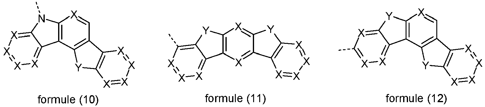


 X est pour chaque occurrence, de manière identique ou différente, CR1 ou N, où de préférence, un maximum de 2 symboles X par cycle représentent N ;Y est pour chaque occurrence, de manière identique ou différente, C(R1)2, NR1, O ou S ;n est 0 ou 1, où n égal à 0 signifie qu'aucun groupe Y n'est lié au niveau de cette position et qu'en lieu et place, des radicaux R1 sont liés aux atomes de carbone correspondants.
 - Dispositif électroluminescent organique selon la revendication 11, caractérisé en ce que le matériau de transport d'électrons est sélectionné parmi les composés de la formule (45) ou (46) :
 E est, de manière identique ou différente pour chaque occurrence, une liaison simple, NR, CR2, O ou S ;Ar1 est, en association avec les atomes de carbone qui sont représentés de façon explicite, un système de cycle aromatique ou hétéroaromatique qui comporte de 5 à 30 atomes de cycle aromatique, lequel système de cycle peut être substitué par un radical ou par plusieurs radicaux R ;Ar2, Ar3 sont, de manière identique ou différente pour chaque occurrence, en association avec les atomes de carbone qui sont représentés de façon explicite, un système de cycle aromatique ou hétéroaromatique qui comporte de 5 à 30 atomes de cycle aromatique, lequel système de cycle peut être substitué par un radical ou par plusieurs radicaux R ;L est, pour m = 2, une liaison simple ou un groupe divalent, ou, pour m = 3, un groupe trivalent ou, pour m = 4, un groupe tétravalent, lequel groupe est dans chaque cas lié à Ar1, Ar2 ou Ar3 au niveau de n'importe quelle position souhaitée ou est lié à E en lieu et place d'un radical R ;m est 2, 3 ou 4.
 - Dispositif électroluminescent organique selon la revendication 14, caractérisé en ce que le groupe Ar1 représente un groupe de la formule (47), (48), (49) ou (50), soit les formules qui suivent :
 W est, de manière identique ou différente pour chaque occurrence, CR ou N ; ou deux groupes adjacents W représentent un groupe de la formule (51) ou (52) :
 V est NR, O ou S ;et/ou en ce que le groupe Ar2 représente un groupe de l'une des formules (53), (54) et (55) :
et/ou en ce que le groupe Ar3 représente un groupe de l'une des formules (56), (57), (58) et (59) :
- Dispositif électroluminescent organique selon la revendication 11, caractérisé en ce que le matériau de transport d'électrons est sélectionné parmi les composés des formules (70) et (71) :
 Ar4 est pour chaque occurrence, de manière identique ou différente, un système de cycle aromatique ou hétéroaromatique qui comporte de 5 à 80 atomes de cycle aromatique, de préférence jusqu'à 60 atomes de cycle aromatique, lequel système de cycle peut dans chaque cas être substitué par un ou par plusieurs groupe(s) R.
 - Procédé pour la production d'un dispositif électroluminescent organique selon une ou plusieurs des revendications 1 à 16, caractérisé en ce qu'au moins une couche est appliquée au moyen d'un procédé de sublimation et/ou en ce qu'au moins une couche est appliquée au moyen d'un procédé OVPD (dépôt organique en phase vapeur) ou à l'aide d'une sublimation à gaz porteur et/ou en ce qu'au moins une couche est appliquée à partir d'une solution, au moyen d'un dépôt/ revêtement à la tournette/par centrifugation ou au moyen d'un procédé d'impression.
Priority Applications (1)
| Application Number | Priority Date | Filing Date | Title |
|---|---|---|---|
| EP14711162.9A EP2984152B2 (fr) | 2013-04-08 | 2014-03-18 | Dispositif électroluminescent organique |
Applications Claiming Priority (3)
| Application Number | Priority Date | Filing Date | Title |
|---|---|---|---|
| EP13001796 | 2013-04-08 | ||
| EP14711162.9A EP2984152B2 (fr) | 2013-04-08 | 2014-03-18 | Dispositif électroluminescent organique |
| PCT/EP2014/000742 WO2014166586A1 (fr) | 2013-04-08 | 2014-03-18 | Dispositif électroluminescent organique |
Publications (3)
| Publication Number | Publication Date |
|---|---|
| EP2984152A1 EP2984152A1 (fr) | 2016-02-17 |
| EP2984152B1 EP2984152B1 (fr) | 2018-04-25 |
| EP2984152B2 true EP2984152B2 (fr) | 2022-01-05 |
Family
ID=48128050
Family Applications (1)
| Application Number | Title | Priority Date | Filing Date |
|---|---|---|---|
| EP14711162.9A Active EP2984152B2 (fr) | 2013-04-08 | 2014-03-18 | Dispositif électroluminescent organique |
Country Status (7)
| Country | Link |
|---|---|
| US (1) | US20160093812A1 (fr) |
| EP (1) | EP2984152B2 (fr) |
| JP (1) | JP6553022B2 (fr) |
| KR (1) | KR102177883B1 (fr) |
| CN (2) | CN105102581A (fr) |
| TW (1) | TWI661028B (fr) |
| WO (1) | WO2014166586A1 (fr) |
Families Citing this family (40)
| Publication number | Priority date | Publication date | Assignee | Title |
|---|---|---|---|---|
| KR102261235B1 (ko) | 2011-11-22 | 2021-06-04 | 이데미쓰 고산 가부시키가이샤 | 방향족 복소 고리 유도체, 유기 일렉트로루미네선스 소자용 재료 및 유기 일렉트로루미네선스 소자 |
| JP6182217B2 (ja) | 2013-11-13 | 2017-08-16 | 出光興産株式会社 | 化合物、有機エレクトロルミネッセンス素子用材料、有機エレクトロルミネッセンス素子および電子機器 |
| US10374167B2 (en) | 2013-11-15 | 2019-08-06 | Merck Patent Gmbh | Compound with novel six-membered ring structure for use in organic electronic devices |
| US10734587B2 (en) * | 2014-03-13 | 2020-08-04 | Merck Patent Gmbh | Formulations of luminescent compounds |
| JP6640735B2 (ja) | 2014-11-28 | 2020-02-05 | 出光興産株式会社 | 化合物、有機エレクトロルミネッセンス素子用材料、有機エレクトロルミネッセンス素子および電子機器 |
| US9806269B2 (en) | 2014-12-05 | 2017-10-31 | Lg Display Co., Ltd. | Delayed fluorescence compound, and organic light emitting diode and display device using the same |
| WO2016091353A1 (fr) | 2014-12-12 | 2016-06-16 | Merck Patent Gmbh | Composés organiques comprenant des groupes solubles |
| KR102343572B1 (ko) * | 2015-03-06 | 2021-12-28 | 삼성디스플레이 주식회사 | 유기 발광 소자 |
| GB201507340D0 (en) | 2015-04-29 | 2015-06-10 | Univ St Andrews | Light emitting devices and compounds |
| US10435390B2 (en) | 2015-06-03 | 2019-10-08 | Lg Chem, Ltd. | Heterocyclic compound and organic light emitting device including same |
| KR102417039B1 (ko) * | 2015-08-20 | 2022-07-05 | 덕산네오룩스 주식회사 | 유기전기 소자용 화합물, 이를 이용한 유기전기소자 및 그 전자 장치 |
| CN105418486A (zh) | 2015-12-25 | 2016-03-23 | 上海天马有机发光显示技术有限公司 | 有机电致发光化合物及其有机光电装置 |
| CN105418617B (zh) | 2015-12-25 | 2018-03-06 | 上海天马有机发光显示技术有限公司 | 有机电致发光化合物及其有机光电装置 |
| JP6788314B2 (ja) * | 2016-01-06 | 2020-11-25 | コニカミノルタ株式会社 | 有機エレクトロルミネッセンス素子、有機エレクトロルミネッセンス素子の製造方法、表示装置及び照明装置 |
| CN107056748B (zh) * | 2016-04-25 | 2020-12-11 | 中节能万润股份有限公司 | 一种以三嗪和酮为核心的化合物及其在有机电致发光器件上的应用 |
| JP6664514B2 (ja) * | 2016-05-10 | 2020-03-13 | エルジー・ケム・リミテッド | 有機電界発光素子およびその製造方法 |
| KR102651014B1 (ko) | 2016-05-26 | 2024-03-26 | 삼성디스플레이 주식회사 | 함질소 화합물 및 이를 포함하는 유기 전계 발광 소자 |
| EP3266772B1 (fr) * | 2016-07-06 | 2019-04-24 | Cynora Gmbh | Molécules organiques, en particulier destinées à être utilisées dans des composants optoélectroniques |
| JP6691848B2 (ja) * | 2016-07-21 | 2020-05-13 | 株式会社デンソー | 発光素子、表示装置および電子機器 |
| CN106206974B (zh) * | 2016-09-06 | 2018-03-23 | 苏州大学 | 热致延迟荧光有机电致发光体系以及使用该体系的发光二极管 |
| CN108023022B (zh) * | 2016-11-03 | 2020-07-14 | 上海和辉光电有限公司 | 一种有机电致发光器件及电子设备 |
| KR20180062561A (ko) | 2016-11-30 | 2018-06-11 | 삼성디스플레이 주식회사 | 다환 화합물 및 이를 포함하는 유기 전계 발광 소자 |
| KR20180063426A (ko) | 2016-12-01 | 2018-06-12 | 삼성디스플레이 주식회사 | 방향족 화합물 및 이를 포함하는 유기 전계 발광 소자 |
| KR102138823B1 (ko) * | 2017-12-27 | 2020-07-28 | 삼성에스디아이 주식회사 | 유기 광전자 소자 및 표시 장치 |
| CN109705126A (zh) * | 2018-06-29 | 2019-05-03 | 赛洛普(武汉)科技有限公司 | 一种用于有机电致发光器件的化合物及应用 |
| US20200017508A1 (en) * | 2018-07-13 | 2020-01-16 | Universal Display Corporation | Organic electroluminescent materials and devices |
| US11482681B2 (en) | 2018-07-27 | 2022-10-25 | Idemitsu Kosan Co., Ltd. | Compound, material for organic electroluminescence element, organic electroluminescence element, and electronic device |
| US11459340B2 (en) | 2018-09-18 | 2022-10-04 | Nikang Therapeutics, Inc. | Tri-substituted heteroaryl derivatives as Src homology-2 phosphatase inhibitors |
| TWI767148B (zh) | 2018-10-10 | 2022-06-11 | 美商弗瑪治療公司 | 抑制脂肪酸合成酶(fasn) |
| KR102622078B1 (ko) | 2018-12-13 | 2024-01-05 | 엘지디스플레이 주식회사 | 유기발광다이오드 및 이를 포함하는 유기발광장치 |
| KR20200091979A (ko) | 2019-01-23 | 2020-08-03 | 삼성디스플레이 주식회사 | 유기 발광 소자 |
| KR20210051998A (ko) * | 2019-10-31 | 2021-05-10 | 삼성전자주식회사 | 발광 소자, 그 제조방법 및 이를 포함한 표시 장치 |
| CN110878062A (zh) * | 2019-11-27 | 2020-03-13 | 武汉华星光电半导体显示技术有限公司 | 热活化延迟荧光材料及其制备方法和电致发光器件 |
| KR20220157456A (ko) * | 2020-03-23 | 2022-11-29 | 메르크 파텐트 게엠베하 | 유기 전계 발광 디바이스용 재료 |
| CN111620882B (zh) * | 2020-06-12 | 2021-08-31 | 欧洛德(武汉)光电科技有限公司 | 新型用于有机电致发光器件的化合物及应用 |
| CN111635409B (zh) * | 2020-06-12 | 2021-10-12 | 欧洛德(武汉)光电科技有限公司 | 引入环状酰胺结构用于有机电致发光器件的化合物及应用 |
| CN111620883B (zh) * | 2020-06-12 | 2021-09-28 | 欧洛德(武汉)光电科技有限公司 | 一种用于有机电致发光器件的新型化合物 |
| KR102493132B1 (ko) * | 2020-09-11 | 2023-01-31 | 삼성디스플레이 주식회사 | 발광 소자 및 이를 포함한 전자 장치 |
| EP4242200A2 (fr) * | 2020-11-05 | 2023-09-13 | Idemitsu Kosan Co., Ltd | Composé, matériau pour élément électroluminescent organique, élément électroluminescent organique et dispositif électronique |
| WO2023140710A1 (fr) * | 2022-01-21 | 2023-07-27 | Samsung Display Co., Ltd. | Molécules organiques pour dispositifs optoélectroniques |
Family Cites Families (19)
| Publication number | Priority date | Publication date | Assignee | Title |
|---|---|---|---|---|
| DE10357315A1 (de) * | 2003-12-05 | 2005-07-07 | Covion Organic Semiconductors Gmbh | Organisches Elektrolumineszenzelement |
| US20070013451A1 (en) * | 2004-04-21 | 2007-01-18 | Motorola, Inc. | Circuits for use in radio communications |
| JP4593631B2 (ja) * | 2005-12-01 | 2010-12-08 | 新日鐵化学株式会社 | 有機電界発光素子用化合物及び有機電界発光素子 |
| CN101511834B (zh) * | 2006-11-09 | 2013-03-27 | 新日铁化学株式会社 | 有机场致发光元件用化合物及有机场致发光元件 |
| JP2009004491A (ja) * | 2007-06-20 | 2009-01-08 | Fujifilm Corp | 有機電界発光素子 |
| DE102008033943A1 (de) * | 2008-07-18 | 2010-01-21 | Merck Patent Gmbh | Neue Materialien für organische Elektrolumineszenzvorrichtungen |
| DE102009009277B4 (de) * | 2009-02-17 | 2023-12-07 | Merck Patent Gmbh | Organische elektronische Vorrichtung, Verfahren zu deren Herstellung und Verwendung von Verbindungen |
| JP5523060B2 (ja) * | 2009-03-16 | 2014-06-18 | キヤノン株式会社 | 新規ビクリセン化合物及びこれを有する有機発光素子 |
| DE102009023155A1 (de) * | 2009-05-29 | 2010-12-02 | Merck Patent Gmbh | Materialien für organische Elektrolumineszenzvorrichtungen |
| DE102009031021A1 (de) * | 2009-06-30 | 2011-01-05 | Merck Patent Gmbh | Materialien für organische Elektrolumineszenzvorrichtungen |
| JP5475003B2 (ja) * | 2009-11-27 | 2014-04-16 | シャープ株式会社 | 有機エレクトロルミネッセンス素子、およびその製造方法、ならびに有機エレクトロルミネッセンス表示装置 |
| EP3176241A1 (fr) * | 2009-12-07 | 2017-06-07 | Nippon Steel & Sumikin Chemical Co., Ltd. | Matériau organique électroluminescent et élément organique électroluminescent |
| US9487548B2 (en) * | 2009-12-14 | 2016-11-08 | Udc Ireland Limited | Metal complexes comprising diazabenzimidazolocarbene ligands and the use thereof in OLEDs |
| DE102010019306B4 (de) * | 2010-05-04 | 2021-05-20 | Merck Patent Gmbh | Organische Elektrolumineszenzvorrichtungen |
| DE102010027317A1 (de) * | 2010-07-16 | 2012-01-19 | Merck Patent Gmbh | Metallkomplexe |
| KR20180049247A (ko) * | 2010-11-11 | 2018-05-10 | 닛토덴코 가부시키가이샤 | 하이브리드 복합 방출성 구조체 및 이를 이용한 발광 장치들 |
| WO2013011955A1 (fr) * | 2011-07-15 | 2013-01-24 | 国立大学法人九州大学 | Matériau à fluorescence retardée et élément d'électroluminescence organique utilisant ledit matériau |
| CN103650195B (zh) * | 2011-07-15 | 2016-12-07 | 九州有机光材股份有限公司 | 有机电致发光元件及其所使用的化合物 |
| US9735385B2 (en) | 2011-08-22 | 2017-08-15 | Merck Patent Gmbh | Organic electroluminescence device |
-
2014
- 2014-03-18 CN CN201480018014.4A patent/CN105102581A/zh active Pending
- 2014-03-18 CN CN202010151199.3A patent/CN111430557A/zh active Pending
- 2014-03-18 US US14/782,621 patent/US20160093812A1/en active Pending
- 2014-03-18 EP EP14711162.9A patent/EP2984152B2/fr active Active
- 2014-03-18 JP JP2016506801A patent/JP6553022B2/ja active Active
- 2014-03-18 KR KR1020157031343A patent/KR102177883B1/ko active IP Right Grant
- 2014-03-18 WO PCT/EP2014/000742 patent/WO2014166586A1/fr active Application Filing
- 2014-04-03 TW TW103112539A patent/TWI661028B/zh active
Also Published As
| Publication number | Publication date |
|---|---|
| KR102177883B1 (ko) | 2020-11-12 |
| JP6553022B2 (ja) | 2019-07-31 |
| EP2984152B1 (fr) | 2018-04-25 |
| US20160093812A1 (en) | 2016-03-31 |
| EP2984152A1 (fr) | 2016-02-17 |
| JP2016514908A (ja) | 2016-05-23 |
| TW201506125A (zh) | 2015-02-16 |
| KR20150143552A (ko) | 2015-12-23 |
| CN105102581A (zh) | 2015-11-25 |
| WO2014166586A1 (fr) | 2014-10-16 |
| TWI661028B (zh) | 2019-06-01 |
| CN111430557A (zh) | 2020-07-17 |
Similar Documents
| Publication | Publication Date | Title |
|---|---|---|
| EP2984152B2 (fr) | Dispositif électroluminescent organique | |
| EP2984692B1 (fr) | Dispositif électroluminescent organique comportant une matière à fluorescence retardée thermiquement activée | |
| EP2984151B1 (fr) | Dispositif électroluminescent organique | |
| EP3005433B1 (fr) | Dispositif organique éléctroluminescent | |
| EP3117470B1 (fr) | Dispositif électroluminescent organique | |
| EP2907173B1 (fr) | Dispositif électronique | |
| EP3044286B1 (fr) | Dispositif d'électroluminescence organique | |
| EP2984691B1 (fr) | Dispositif émetteur de lumière organique à fluorescence retardée | |
| EP2303815B1 (fr) | Dispositif électroluminescent organique | |
| DE112010001236B4 (de) | Organische elektrolumineszenzvorrichtung | |
| DE112011102558B4 (de) | Organische Elektrolumineszenzvorrichtung | |
| EP2695213B1 (fr) | Dispositif électroluminescent organique | |
| EP3120396B1 (fr) | Dispositif organique électroluminescent | |
| DE112011101604B4 (de) | Organische Elektrolumineszenzvorrichtung | |
| EP2764558B1 (fr) | Dispositif électroluminescents organiques | |
| EP3209746B1 (fr) | Dispositif électroluminescent organique | |
| WO2020225071A1 (fr) | Dispositif électronique | |
| EP3887378A1 (fr) | Dispositif électronique | |
| EP3887479B1 (fr) | Dispositif électronique | |
| WO2020225069A1 (fr) | Dispositif électronique | |
| WO2021028513A1 (fr) | Dispositif électronique | |
| WO2011035835A1 (fr) | Dispositif électroluminescent organique |
Legal Events
| Date | Code | Title | Description |
|---|---|---|---|
| PUAI | Public reference made under article 153(3) epc to a published international application that has entered the european phase |
Free format text: ORIGINAL CODE: 0009012 |
|
| 17P | Request for examination filed |
Effective date: 20150810 |
|
| AK | Designated contracting states |
Kind code of ref document: A1 Designated state(s): AL AT BE BG CH CY CZ DE DK EE ES FI FR GB GR HR HU IE IS IT LI LT LU LV MC MK MT NL NO PL PT RO RS SE SI SK SM TR |
|
| AX | Request for extension of the european patent |
Extension state: BA ME |
|
| DAX | Request for extension of the european patent (deleted) | ||
| 17Q | First examination report despatched |
Effective date: 20161007 |
|
| STAA | Information on the status of an ep patent application or granted ep patent |
Free format text: STATUS: EXAMINATION IS IN PROGRESS |
|
| RIC1 | Information provided on ipc code assigned before grant |
Ipc: C09K 11/06 20060101AFI20170412BHEP Ipc: H01L 51/56 20060101ALI20170412BHEP Ipc: H01L 33/00 20100101ALI20170412BHEP Ipc: H01L 27/32 20060101ALI20170412BHEP Ipc: H01L 51/00 20060101ALI20170412BHEP Ipc: H01L 51/50 20060101ALI20170412BHEP |
|
| GRAP | Despatch of communication of intention to grant a patent |
Free format text: ORIGINAL CODE: EPIDOSNIGR1 |
|
| STAA | Information on the status of an ep patent application or granted ep patent |
Free format text: STATUS: GRANT OF PATENT IS INTENDED |
|
| INTG | Intention to grant announced |
Effective date: 20171207 |
|
| GRAS | Grant fee paid |
Free format text: ORIGINAL CODE: EPIDOSNIGR3 |
|
| GRAA | (expected) grant |
Free format text: ORIGINAL CODE: 0009210 |
|
| STAA | Information on the status of an ep patent application or granted ep patent |
Free format text: STATUS: THE PATENT HAS BEEN GRANTED |
|
| AK | Designated contracting states |
Kind code of ref document: B1 Designated state(s): AL AT BE BG CH CY CZ DE DK EE ES FI FR GB GR HR HU IE IS IT LI LT LU LV MC MK MT NL NO PL PT RO RS SE SI SK SM TR |
|
| REG | Reference to a national code |
Ref country code: GB Ref legal event code: FG4D Free format text: NOT ENGLISH |
|
| REG | Reference to a national code |
Ref country code: CH Ref legal event code: EP |
|
| REG | Reference to a national code |
Ref country code: AT Ref legal event code: REF Ref document number: 992893 Country of ref document: AT Kind code of ref document: T Effective date: 20180515 |
|
| REG | Reference to a national code |
Ref country code: IE Ref legal event code: FG4D Free format text: LANGUAGE OF EP DOCUMENT: GERMAN |
|
| REG | Reference to a national code |
Ref country code: DE Ref legal event code: R096 Ref document number: 502014008070 Country of ref document: DE |
|
| REG | Reference to a national code |
Ref country code: NL Ref legal event code: MP Effective date: 20180425 |
|
| REG | Reference to a national code |
Ref country code: LT Ref legal event code: MG4D |
|
| PG25 | Lapsed in a contracting state [announced via postgrant information from national office to epo] |
Ref country code: NL Free format text: LAPSE BECAUSE OF FAILURE TO SUBMIT A TRANSLATION OF THE DESCRIPTION OR TO PAY THE FEE WITHIN THE PRESCRIBED TIME-LIMIT Effective date: 20180425 |
|
| PG25 | Lapsed in a contracting state [announced via postgrant information from national office to epo] |
Ref country code: FI Free format text: LAPSE BECAUSE OF FAILURE TO SUBMIT A TRANSLATION OF THE DESCRIPTION OR TO PAY THE FEE WITHIN THE PRESCRIBED TIME-LIMIT Effective date: 20180425 Ref country code: BG Free format text: LAPSE BECAUSE OF FAILURE TO SUBMIT A TRANSLATION OF THE DESCRIPTION OR TO PAY THE FEE WITHIN THE PRESCRIBED TIME-LIMIT Effective date: 20180725 Ref country code: NO Free format text: LAPSE BECAUSE OF FAILURE TO SUBMIT A TRANSLATION OF THE DESCRIPTION OR TO PAY THE FEE WITHIN THE PRESCRIBED TIME-LIMIT Effective date: 20180725 Ref country code: LT Free format text: LAPSE BECAUSE OF FAILURE TO SUBMIT A TRANSLATION OF THE DESCRIPTION OR TO PAY THE FEE WITHIN THE PRESCRIBED TIME-LIMIT Effective date: 20180425 Ref country code: SE Free format text: LAPSE BECAUSE OF FAILURE TO SUBMIT A TRANSLATION OF THE DESCRIPTION OR TO PAY THE FEE WITHIN THE PRESCRIBED TIME-LIMIT Effective date: 20180425 Ref country code: PL Free format text: LAPSE BECAUSE OF FAILURE TO SUBMIT A TRANSLATION OF THE DESCRIPTION OR TO PAY THE FEE WITHIN THE PRESCRIBED TIME-LIMIT Effective date: 20180425 Ref country code: ES Free format text: LAPSE BECAUSE OF FAILURE TO SUBMIT A TRANSLATION OF THE DESCRIPTION OR TO PAY THE FEE WITHIN THE PRESCRIBED TIME-LIMIT Effective date: 20180425 |
|
| PG25 | Lapsed in a contracting state [announced via postgrant information from national office to epo] |
Ref country code: LV Free format text: LAPSE BECAUSE OF FAILURE TO SUBMIT A TRANSLATION OF THE DESCRIPTION OR TO PAY THE FEE WITHIN THE PRESCRIBED TIME-LIMIT Effective date: 20180425 Ref country code: RS Free format text: LAPSE BECAUSE OF FAILURE TO SUBMIT A TRANSLATION OF THE DESCRIPTION OR TO PAY THE FEE WITHIN THE PRESCRIBED TIME-LIMIT Effective date: 20180425 Ref country code: HR Free format text: LAPSE BECAUSE OF FAILURE TO SUBMIT A TRANSLATION OF THE DESCRIPTION OR TO PAY THE FEE WITHIN THE PRESCRIBED TIME-LIMIT Effective date: 20180425 Ref country code: GR Free format text: LAPSE BECAUSE OF FAILURE TO SUBMIT A TRANSLATION OF THE DESCRIPTION OR TO PAY THE FEE WITHIN THE PRESCRIBED TIME-LIMIT Effective date: 20180726 |
|
| PG25 | Lapsed in a contracting state [announced via postgrant information from national office to epo] |
Ref country code: PT Free format text: LAPSE BECAUSE OF FAILURE TO SUBMIT A TRANSLATION OF THE DESCRIPTION OR TO PAY THE FEE WITHIN THE PRESCRIBED TIME-LIMIT Effective date: 20180827 |
|
| REG | Reference to a national code |
Ref country code: DE Ref legal event code: R026 Ref document number: 502014008070 Country of ref document: DE |
|
| PG25 | Lapsed in a contracting state [announced via postgrant information from national office to epo] |
Ref country code: EE Free format text: LAPSE BECAUSE OF FAILURE TO SUBMIT A TRANSLATION OF THE DESCRIPTION OR TO PAY THE FEE WITHIN THE PRESCRIBED TIME-LIMIT Effective date: 20180425 Ref country code: SK Free format text: LAPSE BECAUSE OF FAILURE TO SUBMIT A TRANSLATION OF THE DESCRIPTION OR TO PAY THE FEE WITHIN THE PRESCRIBED TIME-LIMIT Effective date: 20180425 Ref country code: DK Free format text: LAPSE BECAUSE OF FAILURE TO SUBMIT A TRANSLATION OF THE DESCRIPTION OR TO PAY THE FEE WITHIN THE PRESCRIBED TIME-LIMIT Effective date: 20180425 Ref country code: CZ Free format text: LAPSE BECAUSE OF FAILURE TO SUBMIT A TRANSLATION OF THE DESCRIPTION OR TO PAY THE FEE WITHIN THE PRESCRIBED TIME-LIMIT Effective date: 20180425 Ref country code: RO Free format text: LAPSE BECAUSE OF FAILURE TO SUBMIT A TRANSLATION OF THE DESCRIPTION OR TO PAY THE FEE WITHIN THE PRESCRIBED TIME-LIMIT Effective date: 20180425 |
|
| PLBI | Opposition filed |
Free format text: ORIGINAL CODE: 0009260 |
|
| PLAX | Notice of opposition and request to file observation + time limit sent |
Free format text: ORIGINAL CODE: EPIDOSNOBS2 |
|
| PG25 | Lapsed in a contracting state [announced via postgrant information from national office to epo] |
Ref country code: SM Free format text: LAPSE BECAUSE OF FAILURE TO SUBMIT A TRANSLATION OF THE DESCRIPTION OR TO PAY THE FEE WITHIN THE PRESCRIBED TIME-LIMIT Effective date: 20180425 Ref country code: IT Free format text: LAPSE BECAUSE OF FAILURE TO SUBMIT A TRANSLATION OF THE DESCRIPTION OR TO PAY THE FEE WITHIN THE PRESCRIBED TIME-LIMIT Effective date: 20180425 |
|
| 26 | Opposition filed |
Opponent name: NIPPON STEEL CHEMICAL & MATERIAL CO., LTD. Effective date: 20190125 |
|
| PG25 | Lapsed in a contracting state [announced via postgrant information from national office to epo] |
Ref country code: SI Free format text: LAPSE BECAUSE OF FAILURE TO SUBMIT A TRANSLATION OF THE DESCRIPTION OR TO PAY THE FEE WITHIN THE PRESCRIBED TIME-LIMIT Effective date: 20180425 |
|
| PLAF | Information modified related to communication of a notice of opposition and request to file observations + time limit |
Free format text: ORIGINAL CODE: EPIDOSCOBS2 |
|
| PLBB | Reply of patent proprietor to notice(s) of opposition received |
Free format text: ORIGINAL CODE: EPIDOSNOBS3 |
|
| PG25 | Lapsed in a contracting state [announced via postgrant information from national office to epo] |
Ref country code: MC Free format text: LAPSE BECAUSE OF FAILURE TO SUBMIT A TRANSLATION OF THE DESCRIPTION OR TO PAY THE FEE WITHIN THE PRESCRIBED TIME-LIMIT Effective date: 20180425 |
|
| REG | Reference to a national code |
Ref country code: CH Ref legal event code: PL |
|
| GBPC | Gb: european patent ceased through non-payment of renewal fee |
Effective date: 20190318 |
|
| PG25 | Lapsed in a contracting state [announced via postgrant information from national office to epo] |
Ref country code: LU Free format text: LAPSE BECAUSE OF NON-PAYMENT OF DUE FEES Effective date: 20190318 Ref country code: AL Free format text: LAPSE BECAUSE OF FAILURE TO SUBMIT A TRANSLATION OF THE DESCRIPTION OR TO PAY THE FEE WITHIN THE PRESCRIBED TIME-LIMIT Effective date: 20180425 |
|
| REG | Reference to a national code |
Ref country code: BE Ref legal event code: MM Effective date: 20190331 |
|
| PG25 | Lapsed in a contracting state [announced via postgrant information from national office to epo] |
Ref country code: GB Free format text: LAPSE BECAUSE OF NON-PAYMENT OF DUE FEES Effective date: 20190318 Ref country code: CH Free format text: LAPSE BECAUSE OF NON-PAYMENT OF DUE FEES Effective date: 20190331 Ref country code: LI Free format text: LAPSE BECAUSE OF NON-PAYMENT OF DUE FEES Effective date: 20190331 Ref country code: IE Free format text: LAPSE BECAUSE OF NON-PAYMENT OF DUE FEES Effective date: 20190318 |
|
| PG25 | Lapsed in a contracting state [announced via postgrant information from national office to epo] |
Ref country code: FR Free format text: LAPSE BECAUSE OF NON-PAYMENT OF DUE FEES Effective date: 20190331 Ref country code: BE Free format text: LAPSE BECAUSE OF NON-PAYMENT OF DUE FEES Effective date: 20190331 |
|
| PG25 | Lapsed in a contracting state [announced via postgrant information from national office to epo] |
Ref country code: TR Free format text: LAPSE BECAUSE OF FAILURE TO SUBMIT A TRANSLATION OF THE DESCRIPTION OR TO PAY THE FEE WITHIN THE PRESCRIBED TIME-LIMIT Effective date: 20180425 |
|
| PG25 | Lapsed in a contracting state [announced via postgrant information from national office to epo] |
Ref country code: MT Free format text: LAPSE BECAUSE OF FAILURE TO SUBMIT A TRANSLATION OF THE DESCRIPTION OR TO PAY THE FEE WITHIN THE PRESCRIBED TIME-LIMIT Effective date: 20180425 |
|
| PLAY | Examination report in opposition despatched + time limit |
Free format text: ORIGINAL CODE: EPIDOSNORE2 |
|
| REG | Reference to a national code |
Ref country code: AT Ref legal event code: MM01 Ref document number: 992893 Country of ref document: AT Kind code of ref document: T Effective date: 20190318 |
|
| PLBC | Reply to examination report in opposition received |
Free format text: ORIGINAL CODE: EPIDOSNORE3 |
|
| PG25 | Lapsed in a contracting state [announced via postgrant information from national office to epo] |
Ref country code: AT Free format text: LAPSE BECAUSE OF NON-PAYMENT OF DUE FEES Effective date: 20190318 |
|
| PG25 | Lapsed in a contracting state [announced via postgrant information from national office to epo] |
Ref country code: CY Free format text: LAPSE BECAUSE OF FAILURE TO SUBMIT A TRANSLATION OF THE DESCRIPTION OR TO PAY THE FEE WITHIN THE PRESCRIBED TIME-LIMIT Effective date: 20180425 |
|
| PG25 | Lapsed in a contracting state [announced via postgrant information from national office to epo] |
Ref country code: IS Free format text: LAPSE BECAUSE OF FAILURE TO SUBMIT A TRANSLATION OF THE DESCRIPTION OR TO PAY THE FEE WITHIN THE PRESCRIBED TIME-LIMIT Effective date: 20180825 |
|
| PG25 | Lapsed in a contracting state [announced via postgrant information from national office to epo] |
Ref country code: HU Free format text: LAPSE BECAUSE OF FAILURE TO SUBMIT A TRANSLATION OF THE DESCRIPTION OR TO PAY THE FEE WITHIN THE PRESCRIBED TIME-LIMIT; INVALID AB INITIO Effective date: 20140318 |
|
| PUAH | Patent maintained in amended form |
Free format text: ORIGINAL CODE: 0009272 |
|
| STAA | Information on the status of an ep patent application or granted ep patent |
Free format text: STATUS: PATENT MAINTAINED AS AMENDED |
|
| 27A | Patent maintained in amended form |
Effective date: 20220105 |
|
| AK | Designated contracting states |
Kind code of ref document: B2 Designated state(s): AL AT BE BG CH CY CZ DE DK EE ES FI FR GB GR HR HU IE IS IT LI LT LU LV MC MK MT NL NO PL PT RO RS SE SI SK SM TR |
|
| REG | Reference to a national code |
Ref country code: DE Ref legal event code: R102 Ref document number: 502014008070 Country of ref document: DE |
|
| PG25 | Lapsed in a contracting state [announced via postgrant information from national office to epo] |
Ref country code: MK Free format text: LAPSE BECAUSE OF FAILURE TO SUBMIT A TRANSLATION OF THE DESCRIPTION OR TO PAY THE FEE WITHIN THE PRESCRIBED TIME-LIMIT Effective date: 20180425 |
|
| PGFP | Annual fee paid to national office [announced via postgrant information from national office to epo] |
Ref country code: DE Payment date: 20230125 Year of fee payment: 10 |
|
| P01 | Opt-out of the competence of the unified patent court (upc) registered |
Effective date: 20230518 |