EP2979965A1 - Structure de fixation de guidon - Google Patents
Structure de fixation de guidon Download PDFInfo
- Publication number
- EP2979965A1 EP2979965A1 EP15173628.7A EP15173628A EP2979965A1 EP 2979965 A1 EP2979965 A1 EP 2979965A1 EP 15173628 A EP15173628 A EP 15173628A EP 2979965 A1 EP2979965 A1 EP 2979965A1
- Authority
- EP
- European Patent Office
- Prior art keywords
- handlebar
- bolt
- post
- clamper
- fixing
- Prior art date
- Legal status (The legal status is an assumption and is not a legal conclusion. Google has not performed a legal analysis and makes no representation as to the accuracy of the status listed.)
- Granted
Links
- 230000004308 accommodation Effects 0.000 description 8
- 230000002238 attenuated effect Effects 0.000 description 2
- 239000002828 fuel tank Substances 0.000 description 2
- 238000003754 machining Methods 0.000 description 2
- 230000008961 swelling Effects 0.000 description 2
- 238000005452 bending Methods 0.000 description 1
- 230000005540 biological transmission Effects 0.000 description 1
- 230000007423 decrease Effects 0.000 description 1
- 230000003247 decreasing effect Effects 0.000 description 1
- 230000000994 depressogenic effect Effects 0.000 description 1
- 230000002452 interceptive effect Effects 0.000 description 1
- 238000000034 method Methods 0.000 description 1
- 239000011347 resin Substances 0.000 description 1
- 229920005989 resin Polymers 0.000 description 1
Images


Classifications
-
- B—PERFORMING OPERATIONS; TRANSPORTING
- B62—LAND VEHICLES FOR TRAVELLING OTHERWISE THAN ON RAILS
- B62K—CYCLES; CYCLE FRAMES; CYCLE STEERING DEVICES; RIDER-OPERATED TERMINAL CONTROLS SPECIALLY ADAPTED FOR CYCLES; CYCLE AXLE SUSPENSIONS; CYCLE SIDE-CARS, FORECARS, OR THE LIKE
- B62K21/00—Steering devices
- B62K21/18—Connections between forks and handlebars or handlebar stems
- B62K21/20—Connections between forks and handlebars or handlebar stems resilient
-
- B—PERFORMING OPERATIONS; TRANSPORTING
- B62—LAND VEHICLES FOR TRAVELLING OTHERWISE THAN ON RAILS
- B62K—CYCLES; CYCLE FRAMES; CYCLE STEERING DEVICES; RIDER-OPERATED TERMINAL CONTROLS SPECIALLY ADAPTED FOR CYCLES; CYCLE AXLE SUSPENSIONS; CYCLE SIDE-CARS, FORECARS, OR THE LIKE
- B62K11/00—Motorcycles, engine-assisted cycles or motor scooters with one or two wheels
- B62K11/14—Handlebar constructions, or arrangements of controls thereon, specially adapted thereto
-
- B—PERFORMING OPERATIONS; TRANSPORTING
- B62—LAND VEHICLES FOR TRAVELLING OTHERWISE THAN ON RAILS
- B62K—CYCLES; CYCLE FRAMES; CYCLE STEERING DEVICES; RIDER-OPERATED TERMINAL CONTROLS SPECIALLY ADAPTED FOR CYCLES; CYCLE AXLE SUSPENSIONS; CYCLE SIDE-CARS, FORECARS, OR THE LIKE
- B62K21/00—Steering devices
- B62K21/08—Steering dampers
Definitions
- the present invention relates to a handlebar fixing structure.
- a handlebar fixing structure wherein a handlebar post which clamps a handlebar is fixed to a top bridge at an upper portion of a steering system
- a handlebar fixing structure wherein the handlebar post is fixed through an elastic member in order to prevent transmission of driving vibration, engine vibration and so forth to the hands of the driver (for example, refer to Japanese Patent Laid-Open No. 2012-144145 ).
- the elastic member is interposed between a lower face of the handlebar post and the top bridge.
- an attachment position of the handlebar can be set higher by setting the length of a handlebar post extending upwardly from an upper portion of the steering system longer.
- the handlebar post in the conventional structure is simply elongated upwardly, then the load by a bending moment or the like which acts on the elastic member increases as the length of the handlebar posts increases and the attachment rigidity of the handlebar becomes less likely to be secured. Further, while the attachment rigidity of the handlebar can be secured by making the elastic member harder, absorbency of vibration is decreased.
- the present invention has been made in view of such a situation as described above, and it is an object of the present invention to provide a handlebar fixing structure which allows a handlebar to be attached to a high position and has high vibration absorbency.
- a handlebar fixing structure including: a steering system (35) for steerably supporting a front side traveling unit (2), which is attached for steering to a front portion of a vehicle body, on the vehicle body; a handlebar (30) attached above the steering system (35) and extending in a vehicle widthwise direction; a handlebar post (60) supported above the steering system (35) and supporting the handlebar (30) thereon; and a handlebar clamper (61) attached to the handlebar post (60) for fixing the handlebar (30) to the handlebar post (60); the handlebar clamper (61) including a first clamper member (81) and a second clamper member (82) disposed across a tip end portion (71) of the handlebar post (60) and the handlebar (30) from a direction orthogonal to the vehicle widthwise direction; an elastic member (72) being interposed between the first clamper member (81) and the handlebar post (60) and between the second clamper member (82) and the handlebar post (60); the first clamp
- the handlebar since the handlebar is fixed to the handlebar clamper disposed so as to sandwich the tip end portion of the handlebar post, the handlebar can be attached to a high position and the handlebar clamper can be elastically supported by the elastic members between the handlebar post and the first clamper member and second clamper member. Consequently, the handlebar fixing structure can be obtained which allows the handlebar to be attached to a high position and besides has a high vibration absorbency.
- the handlebar fixing structure is configured such that the abutting faces (86, 93) are provided at a position at which the abutting faces (86, 93) overlap with the bolt (59) as viewed in the vehicle widthwise direction and are disposed on the opposite sides of the bolt (59) in the vehicle widthwise direction.
- the abutting faces are provided at the position at which they overlap with the bolt as viewed in the vehicle widthwise direction and are disposed on the opposite sides of the bolt in the vehicle widthwise direction. Therefore, the axial force of the bolt can be received effectively on the opposite sides in the vehicle widthwise direction in the proximity of the bolt.
- the handlebar fixing structure is configured such that the abutting faces (86, 93) are bent as viewed in an axial direction of the bolt (59).
- the rigidity of the abutting faces can be raised and the axial force of the bolt can be received effectively.
- the handlebar fixing structure is configured such that one of the first clamper member (81) and the second clamper member (82) includes a first female threaded portion (87a) with which the bolt (59) for fixing the first clamper member (81) and the second clamper member (82) to the handlebar post (60) is screwed and a second female threaded portion (84a) with which a clamp bolt (76) for adjusting clamp load to the handlebar (30) is screwed, and a third female threaded portion (89a, 89b) for fixing a different part (96) to the handlebar clamper (61) is provided at an upper portion of the one clamper member (81).
- the plurality of female threaded portions are provided on one of the clamper members, it is only necessary to perform machining of the female threaded portions only for one of the clamper members, and the handlebar clamper can be manufactured readily. Further, the different part can be provided above the steering system by a simple configuration making use of the third female threaded portions.
- the handlebar fixing structure is configured such that each of the handlebar post (60), the first clamper member (81) and the second clamper member (82) includes a pair of left and right parts, and a hydraulic chamber (46a) of a steering damper apparatus (45) is disposed between the left and right handlebar posts (60).
- the steering damper apparatus can be provided making use of the space between the left and right handlebar posts.
- the handlebar fixing structure is configured such that the hydraulic chamber (46a) is disposed below the handlebar (30).
- the steering damper apparatus can be provided making use of the space below the handlebar.
- the handlebar fixing structure is configured such that the handlebar clamper (61) includes a lower fixing portion (75) fastened by the bolt (59) and fixed to the handlebar post (60), an upper fixing portion (77) to which a clamp bolt (76) for adjusting clamp load to the handlebar (30) is fastened, and a handlebar fixing portion (78) provided between the upper fixing portion (77) and the lower fixing portion (75) and sandwiching the handlebar (30), and the elastic member (72) is fitted with the bolt (59) and provided on the inner side of the lower fixing portion (75) while the abutting faces (86, 93) are provided on the lower fixing portion (75).
- the handlebar clamper can be elastically supported on the handlebar posts through the elastic members provided on the lower fixing portion of the handlebar clamper extending upwardly and downwardly, and the handlebar can be fixed to the handlebar fixing portion above the lower fixing portion. Consequently, the clamp load can be adjusted readily by the upper fixing portion.
- a steering damper fixing structure for a saddle type vehicle including: a steering system (35) for steerably supporting a front side traveling unit (2), which is attached for steering to a front portion of a vehicle body, on the vehicle body; a handlebar (30) attached above the steering system (35) and extending in a vehicle widthwise direction; a pair of left and right handlebar posts (60) supported above the steering system (35) and supporting the handlebar (30) thereon; and a steering damper apparatus (45) including a hydraulic chamber (46a) supported for integral pivotal motion with the steering system (35) at a position between the left and right handlebar posts (60) at which the hydraulic chamber (46a) overlaps with the handlebar (30) as viewed from a steering shaft direction, wherein the hydraulic chamber (46a) is fastened to the steering system (35) by a bolt (53) directed in a forward and rearward direction.
- the hydraulic chamber is fastened to the steering system by the bolt directed in the forward and rearward direction, a part which is positioned above the handlebar or the steering damper apparatus does not interfere with a tool path for the bolt directed in the forward and rearward direction. Therefore, the maintainability of the steering damper fixing structure and the degree of freedom in disposition of a different part can be improved.
- the steering damper fixing structure is configured such that the pair of left and right handlebar posts (60) are configured independently of each other, the hydraulic chamber (46a) is fixed to a damper stay (47) fixed to and supported on each of the left and right handlebar posts (60), and the damper stay (47) is fastened to the handlebar posts (60) by the bolt (53) directed in the forward and rearward direction.
- the hydraulic chamber can be fixed. Therefore, it is possible to easily cope with a change in setting of the left and right handlebar posts.
- each of the handlebar posts (60) includes a post (64) for supporting the handlebar (30) at an upper portion of the handlebar posts (60) and a base unit (63) configured independently of the post (64) on a lower side of the post (64), and a bracket portion (67) to which the hydraulic chamber (46a) is fastened is provided on the base unit (63) and the base unit (63) is fastened together with the post to the steering system (35).
- the posts having a function for supporting the handlebar and the bracket portions having a function for supporting the hydraulic chamber are separated from each other, it is possible to cope with a change in shape of the handlebar and the hydraulic chamber individually. Therefore, the degree of freedom in change of setting is high.
- the steering damper fixing structure is configured such that the bolt (53) directed in the forward and rearward direction is disposed substantially in parallel to an upper face of a top bridge (36) of the steering system (35).
- the bolt directed in the forward and rearward direction is disposed substantially in parallel to the upper face of the top bridge of the steering system, the bolt directed in the forward and rearward direction can be mounted and dismounted readily making use of the space along the upper face of the top bridge.
- the handlebar fixing structure can be obtained which allows the handlebar to be attached to a high position and besides has a high vibration absorbency.
- the axial force of the bolt can be received effectively on the opposite sides in the vehicle widthwise direction in the proximity of the bolt.
- the rigidity of the abutting faces can be raised, and the axial force of the bolt can be received effectively.
- the handlebar clamper having the female threaded portion can be manufactured readily, and a different part can be provided above the steering system by a simple configuration.
- the steering damper apparatus can be provided making use of the space between the left and right handlebar posts.
- the steering damper apparatus can be provided making use of the space below the handlebar.
- the handlebar clamper can be elastically supported on the handlebar post through the elastic members provided on the lower fixing portion of the handlebar clamper, and the handlebar can be fixed to the handlebar fixing portion. Consequently, the clamp load can be adjusted readily by the upper fixing portion.
- the bolt directed in the forward and rearward direction can be mounted and dismounted readily making use of the space along the upper face of the top bridge.
- FIG. 1 is a right side elevational view of a motorcycle 1 according to an embodiment of the present invention. It is to be noted that, where left and right members are provided in pair, only right one of the members is depicted in FIG. 1 .
- the motorcycle 1 is a vehicle in which an engine 10 as a power unit is supported on a vehicle body frame F and a pair of left and right front forks 11 are steerably supported at a front end of the vehicle body frame F.
- a front wheel 2 front side traveling unit
- a swing arm 12 is provided at a rear portion of the vehicle body frame F and supports a rear wheel 3 thereon.
- the motorcycle 1 is a saddle type vehicle wherein a seat 13 is provided above a central portion in the forward and rearward direction of the vehicle body frame F such that an occupant is to sit astride thereon.
- the vehicle body frame F includes a head pipe 14 ( FIG. 3 ), a pair of left and right main frames 15, a pair of left and right pivot frames 16, a down frame (not depicted), and an under frame (not depicted).
- the head pipe 14 is provided at a front end of the vehicle body frame F.
- the left and right main frames 15 extend in a rearwardly obliquely downwardly inclined relationship from the head pipe 14.
- the left and right pivot frames 16 extend downwardly from a rear end of the main frame 15.
- the down frame extends rearwardly downwardly from a rear face of a lower portion of the head pipe 14.
- the under frame extends downwardly in a leftwardly and rightwardly branching relationship from the down frame and is bent substantially horizontally in a rearward direction and then coupled with a lower end of the pivot frames 16.
- a fuel tank 17 is disposed in front of the seat 13 and extends upwardly and downwardly along the left and right sides of the main frames 15.
- the motorcycle 1 includes a vehicle body cover made of resin.
- the vehicle body cover includes a pair of left and right shrouds 20, a tank cover 21, an undercover 22, and a pair of left and right fork covers 23.
- the left and right shrouds 20 cover an upper portion of the front forks 11 and the down frame from the side.
- the tank cover 21 covers the fuel tank 17 from the upper side.
- the undercover 22 covers the under frame and the engine 10 from the lower side.
- the left and right fork covers 23 cover a lower portion of the front forks 11.
- a front fender 24 is fixed to the front forks 11 and covers the front wheel 2 from the upper side.
- a pair of left and right steps 25 are provided at a lower ends of the pivot frames 16 such that the occupant can place the feet thereof on the steps 25.
- a front stay 26 is fixed at a front portion of the head pipe 14 and projects forwardly, and a headlamp 27, a windscreen 28 of a shape of a plate and meters 29 are supported on the front stay 26.
- a handlebar 30 is provided above the front forks 11 such that the occupant can steer the front wheel 2 therethrough.
- the opposite ends of the handlebar 30 in the vehicle widthwise direction are covered with handlebar covers 31 from the front side.
- FIG. 2 is a left side elevational view of a fixing structure for the handlebar 30.
- FIG. 3 is a view of the fixing structure for the handlebar 30 as viewed from the front side in a bolt fastening direction.
- FIG. 4 is a view of the fixing structure for the handlebar 30 as viewed from the rear side in the bolt fastening direction. It is to be noted that the head pipe 14 is depicted only in FIG. 3 . Further, a bracket 96 hereinafter described is depicted only in FIG. 2 .
- a steering system 35 for steerably supporting the front wheel 2 on the head pipe 14 includes the front forks 11, a top bridge 36, a bottom bridge 37 ( FIG. 1 ), and a steering shaft 38.
- the top bridge 36 couples upper end portions of the front forks 11 with each other in the vehicle widthwise direction.
- the bottom bridge 37 couples intermediate portions in the upward and downward direction of the front forks 11 with each other in the vehicle widthwise direction.
- the steering shaft 38 is supported for rotation in the head pipe 14.
- the head pipe 14 is positioned at the center in the vehicle widthwise direction.
- a predetermined caster angle is set to the steering system 35, and the head pipe 14 is disposed in a rearwardly inclined relationship in accordance with the caster angle. Also an axial line 38a of the steering shaft 38 and axial lines 11a of the front forks 11 are provided substantially in parallel to the head pipe 14 and are inclined rearwardly.
- the steering shaft 38 extends upwardly from a central portion of the bottom bridge 37 and is inserted from below in the head pipe 14.
- the top bridge 36 is coupled with an upper end portion of the head pipe 14 which projects upwardly as depicted in FIG. 3 .
- the steering shaft 38 is supported for rotation on the head pipe 14 by a pair of bearings (not depicted) provided at an upper end and a lower end of the inside of the head pipe 14.
- a nut 39 is fastened to an upper end portion of the steering shaft 38 and presses the bearing on the upper end side in the axial direction.
- the top bridge 36 is formed in the form of a plate elongated in the vehicle widthwise direction rather than in the forward and rearward direction, and has a shaft hole 40 provided at a central portion of the top bridge 36 in the vehicle widthwise direction.
- the top bridge 36 is supported on the nut 39 by an upper end portion of the steering shaft 38 fitted in the shaft hole 40 thereof.
- the top bridge 36 is fixed to the steering shaft 38 by a top nut 41 fastened to an upper end of the steering shaft 38 which projects upwardly from the shaft hole 40.
- Each of the top bridge 36 and the bottom bridge 37 has a pair of fork supporting hole portions 42 (the hole portions 42 of the bottom bridge 37 are not depicted) provided at the opposite end portions thereof in the vehicle widthwise direction.
- the front forks 11 are inserted in the fork supporting hole portions 42.
- the front forks 11 are fixed by fork fixing bolts 42a which reduce the diameter of the fork supporting hole portions 42 and are tightened therebetween.
- the front wheel 2 is supported for rotation on an axle 2a ( FIG. 1 ) provided at a lower end of the front forks 11.
- the handlebar 30 has a straight portion 30a extending straightly in the vehicle widthwise direction, and a pair of extensions 30b bent rearwardly upwardly from the straight portion 30a and extending to the outer sides in the vehicle widthwise direction.
- a steering damper apparatus 45 is provided in a space between the handlebar 30 and top bridge 36 and attenuates a pivotal motion of the steering system 35.
- FIG. 5 is an exploded perspective view of the steering damper apparatus 45.
- the steering damper apparatus 45 includes a damper apparatus main body 46 of the hydraulic type, a damper stay 47, a vehicle body side fixing member 48 and a pin 49.
- the damper stay 47 is attached to a lower face of the damper apparatus main body 46.
- the vehicle body side fixing member 48 is fixed to the head pipe 14.
- the pin 49 is provided uprightly on the vehicle body side fixing member 48.
- the damper apparatus main body 46 includes a substantially box-shaped case 46a having a hydraulic chamber in the inside thereof, and an arm 46b provided in the hydraulic chamber and pivotally movable in an interlocking relationship with a movable member (not depicted) which moves against the hydraulic pressure.
- the arm 46b extends from a pivot shaft 46g ( FIG. 11 ) projecting from a central portion of a lower face of the case 46a toward the rear side of the vehicle and pivots around the pivot shaft 46g.
- the damper apparatus main body 46 includes operation portions 46c and 46d provided on an upper face of the case 46a for adjusting the attenuation force and so forth.
- the case 46a includes a stepped portion 46e provided at a front portion thereof and having an upper face recessed by one stage. Further, a pair of fixing hole portions 46f are provided at left and right end portions of a front portion of the case 46a, and a pair of case fixing bolts 50 are fitted in the fixing hole portions 46f and fasten the case 46a to the
- the damper stay 47 includes a pair of fastening portions 51 of a shape of a block fixed to a lower face of the fixing hole portions 46f of the case 46a and a connection portion 52 for connecting the fastening portions 51 to each other in the vehicle widthwise direction.
- the connection portion 52 is formed in an arcuate shape projected toward the front side so as not to interfere with a front end portion of the arm 46b.
- Each of the fastening portions 51 has a female threaded portion 51a to which a case fixing bolt 50 is fastened, and an outer side female threaded portion 51b provided on the outer side of the female threaded portion 51a in the vehicle widthwise direction.
- the outer side female threaded portion 51b is a threaded hole extending in the forward and rearward direction of the vehicle.
- a pair of stay fixing bolts 53 (bolts directed in the forward and rearward direction) are fastened to the outer side female threaded portions 51b to fix the damper stay 47 to the top bridge 36 side.
- the vehicle body side fixing member 48 has an outer circumferential portion 48a, a flange portion 48b and a hole 48c.
- the outer circumferential portion 48a is fitted with an outer periphery of an upper end portion of the head pipe 14.
- the flange portion 48b extends toward the inner side from an upper edge of the outer circumferential portion 48a and contacts with an upper face of the head pipe 14.
- the steering shaft 38 and the nut 39 pass through the hole 48c.
- the vehicle body side fixing member 48 has a boss portion 54 provided at a rear portion thereof and projecting upwardly, and the pin 49 is fixed to the boss portion 54.
- the vehicle body side fixing member 48 is formed in such a split clamp type that an open portion 55 extending in a diametrical direction is provided at a front end portion of the vehicle body side fixing member 48.
- a split fastening bolt 56 is provided at a front end portion of the vehicle body side fixing member 48 and is fastened so as to close the open portion 55.
- the vehicle body side fixing member 48 is disposed such that a lower face of the flange portion 48b thereof is abutted with an upper face of the head pipe 14.
- the vehicle body side fixing member 48 is fixed to the head pipe 14 such that the outer circumferential portion 48a thereof holds the head pipe 14 by fastening force of the split fastening bolt 56.
- the vehicle body side fixing member 48 is mounted against rotation on the head pipe 14 and does not rotate.
- a rear portion of the vehicle body side fixing member 48 projects rearwardly from below the top bridge 36, and the pin 49 extends upwardly along a rear face of the top bridge 36.
- the damper apparatus main body 46 is fixed above the top bridge 36 and rotates together with the steering system 35.
- the arm 46b of the damper apparatus main body 46 projects rearwardly from above the top bridge 36, and the pin 49 is coupled at an upper end thereof with a rear end portion of the arm 46b.
- the arm 46b can pivotally move around the pin 49.
- the handlebar fixing structure for fixing the handlebar 30 to the top bridge 36 includes a pair of left and right handlebar posts 60, and a pair of left and right handlebar clampers 61.
- the handlebar posts 60 are fixed to an upper face of the top bridge 36.
- the handlebar clampers 61 are fixed to the handlebar posts 60 and support the handlebar 30 thereon.
- the handlebar posts 60 and the handlebar clampers 61 are fixedly fastened to each other by fixing bolts 59 (bolts) which are fitted in the handlebar posts 60 and the handlebar clampers 61 in the forward and rearward direction.
- the handlebar posts 60 and the handlebar clampers 61 are disposed between the steering shaft 38 and the left and right front forks 11, respectively.
- FIG. 6 is an exploded perspective view of the handlebar posts 60 and the handlebar clampers 61.
- FIG. 7 is a left side elevational view of an upper portion of the handlebar fixing structure.
- FIG. 8 is a sectional view taken along line VIII-VIII of FIG. 3 . In FIGS. 7 and 8 , the handlebar 30, front forks 11, head pipe 14 and so forth are not depicted.
- the top bridge 36 includes a pair of handlebar post fixing portions 62 disposed between the shaft hole 40 and the left and right fork supporting hole portions 42 and having the handlebar posts 60 fixed thereto.
- Each of the handlebar post fixing portions 62 includes a flat face 62a elongated forwardly and rearwardly, a hole 62b provided at the center of the flat face 62a, and a pin hole 62c provided at a rear portion of the flat face 62a.
- each of the handlebar posts 60 includes a base 63 (base portion), a post 64, and a post fixing bolt 65.
- the base 63 is fixed to the flat face 62a of a handlebar post fixing portion 62, and the post 64 is connected to an upper face of the base 63 and supports a handlebar clamper 61 thereon.
- the post fixing bolt 65 projects downwardly from the base 63 and is inserted in the hole 62b.
- Each of the bases 63 includes a base main body 66 of a block shape elongated forwardly and rearwardly, and a bracket portion 67 ( FIG. 6 ) projecting inwardly from a central portion of the base main body 66 in the forward and backward direction.
- the base main body 66 has a hole 66a provided at a central portion thereof in the forward and rearward direction and has a pin hole 66b provided on a lower face of a rear portion thereof.
- the post fixing bolt 65 is fitted in the hole 66a, and a pin 68 for positioning the base 63 is fitted in the pin hole 66b.
- the base main body 66 has a pin hole 66c provided on an upper face of a rear portion thereof, and a pin 69 for positioning the post 64 is fitted in the pin hole 66c.
- the bracket portion 67 has a bolt hole 67a in which a stay fixing bolt 53 ( FIG. 5 ) is inserted.
- the post 64 is formed in a shape of a block and has an abutting portion 70 provided at a lower portion thereof so as to contact with an upper face of the base main body 66. Further, the post 64 has a cylindrical portion 71 (end portion of the handlebar post) provided at an upper portion thereof and extending forwardly and rearwardly.
- a pair of elastic members 72 of a substantially cylindrical shape are attached to a front portion and a rear portion of the cylindrical portion 71. More particularly, the elastic members 72 are made of rubber and formed in a shape of a circular truncated cone and have a bolt hole 72a provided at the center thereof and extending therethrough in the axial direction.
- the cylindrical portion 71 has a front side accommodation portion 71 a provided at a front portion thereof for accommodating the front side elastic member 72 therein and has a rear side accommodation portion 71b provided at a rear portion thereof for accommodating the rear side elastic member 72 therein.
- An annular receiving portion 71c is formed at a central portion of the cylindrical portion 71 in the forward and rearward direction and projects to the inner side in a diametrical direction.
- the front side accommodation portion 71a and the rear side accommodation portion 71b are partitioned by the receiving portion 71c.
- An inner circumferential portion of the receiving portion 71c defines a hole 71d through which a fixing bolt 59 extends.
- the front side accommodation portion 71a and the rear side accommodation portion 71b have an inner circumferential face which is inclined such that the diameter thereof decreases toward the receiving portion 71c side.
- the elastic members 72 are fitted in the front side accommodation portion 71a and the rear side accommodation portion 71b such that tip end portions thereof having a smaller diameter are abutted with the receiving portion 71c.
- the elastic members 72 project outwardly in the axial direction from the front and rear ends of the cylindrical portion 71 in a natural state of the elastic members 72 in which they are not compressed.
- the abutting portion 70 of each of the posts 64 has a pin hole 70a provided on a lower face of a rear portion thereof, and the pin 69 is fitted in the pin hole 70a.
- Each of the post fixing bolts 65 is a stud bolt which is coupled to a lower face of the abutting portion 70 of the post 64.
- the posts 64 and the bases 63 are integrated by fitting the post fixing bolt 65 in the hole 66a of the base 63.
- the post fixing bolt 65 is fitted in the hole 62b and projects downwardly of the top bridge 36, and a post fixing nut 73 is fastened to a lower end portion of the post fixing bolt 65.
- the handlebar post 60 is fixed thereby to the top bridge 36.
- the post 64 and the base 63 are fastened together by the post fixing bolt 65.
- the base 63 and the post 64 are positioned by the pins 68 and 69, respectively.
- FIG. 9 is a sectional view taken along line IX-IX of FIG. 4 .
- each of the handlebar clampers 61 is formed in a hollow tubular shape elongated in the upward and downward direction.
- the handlebar clamper 61 has a lower fixing portion 75, an upper fixing portion 77, and a handlebar fixing portion 78.
- the lower fixing portion 75 is fastened by the fixing bolt 59 and fixed to the handlebar post 60.
- the upper fixing portion 77 has a clamp bolt 76 fastened thereto for adjusting the clamp load to the handlebar 30.
- the handlebar fixing portion 78 is provided between the upper fixing portion 77 and the lower fixing portion 75 and sandwiches the handlebar 30.
- Each of the handlebar clampers 61 is configured from two parts split forwardly and rearwardly and includes a first clamper member 81 configuring the front side half and a second clamper member 82 configuring the rear side half.
- the first clamper member 81 includes a front wall portion 83, a front side boss portion 84, and a pair of side walls 85.
- the front wall portion 83 configures a front face of the handlebar clamper 61.
- the front side boss portion 84 is provided uprightly to the rear side from an upper end portion of the front wall portion 83.
- the side walls 85 are provided uprightly to the rear side from left and right side edges of the front wall portion 83.
- the first clamper member 81 is formed such that the inner side space thereof is open rearwardly and downwardly.
- the side walls 85 are contiguous at an upper end thereof to left and right side edges of a lower face of the front side boss portion 84, and lower ends of the side walls 85 are positioned at lower end portions of the first clamper member 81.
- An abutting wall portion 85a is formed at a lower portion of each of the side walls 85 and contacts with the second clamper member 82 side.
- the abutting wall portions 85a are formed in a thin plate having a cross section which is curved in an arc swelling sidewardly in accordance with the cylindrical portion 71 accommodated inside the abutting wall portions 85a.
- a rear end face of each of the abutting wall portions 85a is an abutting face 86 which abuts with the second clamper member 82, and also the abutting faces 86 are formed so as to be curved in an arc.
- Each of the side walls 85 has a front side handlebar supporting portion 85b provided at an upper portion thereof.
- the front side handlebar supporting portion 85b is cut out in a semicircular shape in accordance with the shape of the straight portion 30a of the handlebar 30.
- a boss 87 is provided at a lower portion of the front wall portion 83 and projects forwardly.
- a first female threaded portion 87a is formed on the boss 87, and the fixing bolt 59 is fastened to the first female threaded portion 87a.
- a second female threaded portion 84a is formed on the front side boss portion 84, and the clamp bolt 76 is fastened to the second female threaded portion 84a.
- Each of the first clamp members 81 has an extension 88 in the form of plate provided at an upper end thereof, and the extension 88 projects forwardly farther than the front wall portion 83.
- An upper face 89 of the first clamper member 81 including an upper face of the extension 88 is formed as a flat face extending substantially in parallel to an upper face of the top bridge 36.
- a pair of third female threaded portions 89a and 89b are formed on the upper face 89.
- Each of the second clamper members 82 includes a rear wall portion 90, a rear side boss portion 91 and a pair of side walls 92 and is formed such that the inside space thereof is open forwardly and downwardly.
- the rear wall portion 90 configures a rear face of the handlebar clamper 61.
- the rear side boss portion 91 is provided uprightly to the front side from an upper end portion of the rear wall portion 90.
- the side walls 92 are provided uprightly to the front side from left and right side edges of the rear wall portion 90.
- the side walls 92 are contiguous at an upper end thereof to left and right side edges of a lower face of the rear side boss portion 91, and lower ends of the side walls 92 are positioned at lower end portions of the second clamper member 82.
- Each of the side walls 92 has an abutting wall portion 92a formed at a lower portion thereof, and the abutting wall portion 92a abuts with the first clamper member 81 side.
- the abutting wall portions 92a are formed so as to be curved in an arc swelling sidewardly in accordance with the cylindrical portion 71 accommodated on the inner side of the abutting wall portions 92a.
- a front end face of each of the abutting wall portions 92a is an abutting face 93 which abuts with the abutting face 86 of the first clamper member 81, and also the abutting faces 93 are formed so as to be curved in an arc.
- the abutting faces 86 and the abutting faces 93 are provided, as viewed in the vehicle widthwise direction (as viewed in side elevation), at a position at which they overlap with a shank 59a of the fixing bolt 59.
- a rear side handlebar supporting portion 92b is provided at an upper portion of each of the side walls 92 and is cut out in a semicircular shape in accordance with the shape of the straight portion 30a of the handlebar 30.
- a hole 94 is provided at a lower portion of the rear wall portion 90, and the fixing bolt 59 is inserted in the hole 94.
- a hole 95 is formed on the rear side boss portion 91, and the clamp bolt 76 is inserted in the hole 95.
- the first clamper member 81 and the second clamper member 82 are disposed such that they sandwich the elastic members 72 disposed on the cylindrical portion 71 of the handlebar post 60 from the front and the rear, respectively. Thereupon, also the handlebar 30 is sandwiched between the front side handlebar supporting portion 85b and the rear side handlebar supporting portion 92b.
- the direction in which the first clamper member 81 and the second clamper member 82 sandwich the cylindrical portion 71 is a direction perpendicular to the vehicle widthwise direction. More particularly, the direction in which the first clamper member 81 and the second clamper member 82 sandwich the cylindrical portion 71 is a direction substantially orthogonal to the axial line 38a of the steering shaft 38 as viewed in side elevation.
- the fixing bolt 59 is inserted into the hole 94 from the rear side such that it extends through the cylindrical portion 71 and the elastic members 72 and is temporarily fixed to the first female threaded portion 87a.
- the clamp bolt 76 is inserted into the hole 95 from the rear side and temporarily fixed to the second female threaded portion 84a.
- the direction in which the fixing bolt 59 and the clamp bolt 76 are inserted is a direction substantially orthogonal to the axial line 38a of the steering shaft 38.
- a gap is formed between the inner face of the front wall portion 83 and the front end of the cylindrical portion 71 and between the inner face of the rear wall portion 90 and the rear end of the cylindrical portion 71. Furthermore, the abutting face 86 and the abutting face 93 extend substantially in parallel to the axial line 38a of the steering shaft 38 as viewed in side elevation.
- the handlebar clamper 61 sandwiches the cylindrical portion 71 through the elastic members 72 and the shank 59a of the fixing bolt 59 is connected to the cylindrical portion 71 through the elastic members 72.
- the handlebar clamper 61 is elastically supported on the handlebar post 60 through the elastic members 72.
- the elastic members 72 are hidden to the inner side of the handlebar clamper 61 and are not exposed to the outside.
- the clamp bolt 76 is tightened by predetermined torque, whereby the clamp force to the handlebar 30 is adjusted and the handlebar 30 is fixed. Also in this state, a gap is formed between the front side boss portion 84 and the rear side boss portion 91.
- the handlebar 30 since the handlebar 30 is fixed to the handlebar clampers 61 disposed so as to sandwich the cylindrical portions 71 at an upper end portion of the handlebar posts 60, the handlebar 30 can be attached at a high position. Further, since the elastic members 72 disposed on the cylindrical portions 71 are each sandwiched by the first clamper member 81 and the second clamper member 82, the handlebar clampers 61 can be elastically supported by the elastic members 72 provided at a position higher than that of a base end portion of each of the handlebar posts 60. Consequently, the load to act upon the elastic members 72 from the handlebar 30 can be reduced in comparison with that by the configuration wherein an elastic member is provided at a base end portion of each handlebar post 60. Further, since the elastic members 72 which are comparatively soft can be used, they are liable to absorb vibration.
- the abutting face 86 and the abutting face 93 are formed so as to be curved in an arc along the outer shape of the cylindrical portion 71, and the abutting face 86 and the abutting face 93 have a curved shape as viewed in the axial direction of the fixing bolt 59. Therefore, while improvement in rigidity of the abutting face 86 and the abutting face 93 by the curved shape is achieved, the handlebar clamper 61 can be reduced in size.
- the bracket portion 67 of the handlebar posts 60 extends toward the inner side in the vehicle widthwise direction.
- the damper apparatus main body 46 is disposed such that the fastening portions 51 of the damper stay 47 abut with the rear face of the bracket portions 67 and is fixed to the handlebar posts 60 by fastening the stay fixing bolts 53 inserted in the bolt holes 67a of the bracket portions 67 from the front side to the outer side female threaded portions 51b ( FIG. 5 ).
- the handlebar 30 is attached to a high position spaced from the top bridge 36 by the handlebar clampers 61, a space can be assured between the center of the top bridge 36 and handlebar 30 and the top bridge 36, and the damper apparatus main body 46 can be disposed in the space.
- the damper apparatus main body 46 is attached to the bracket portions 67 of the handlebar posts 60, the damper apparatus main body 46 can be attached by a simple structure.
- the bracket 96 (different part) is attached to the upper face 89 of the first clamp member 81.
- An attachment base 97 is attached to the bracket 96, and an electric part 98 is fixed to the attachment base 97.
- the bracket 96 has a plate portion 96a extending forwardly and rearwardly along the upper face 89 and a pair of attachment plate portions 96b and 96c extending downwardly in a bent state from a front edge and a rear edge of the plate portion 96a, respectively.
- the bracket 96 is fixed to the upper face 89 by bracket fixing bolts 99a and 99b fitted in the plate portion 96a.
- the bracket fixing bolts 99a and 99b are fastened to the third female threaded portions 89a and 89b ( FIG. 6 ), respectively.
- the attachment base 97 has an attachment portion 97a in the form of a plate to which the electric part 98 is attached, and a pair of leg portions 97b and 97c extend downwardly in a bent state from a front edge and a rear edge of the attachment portion 97a, respectively.
- the attachment base 97 is fastened to the attachment plate portions 96b and 96c of the bracket 96 by base fixing bolts 100 inserted in the leg portions 97b and 97c.
- Each of the base fixing bolts 100 has a bracket anti-vibration member 101 provided thereon, and the attachment base 97 is elastically supported on the bracket 96.
- the attachment portion 97a is disposed substantially in parallel to the upper face of the top bridge 36 and is inclined rearwardly so as to face the occupant side.
- the electric part 98 attached to the attachment portion 97a is, for example, a GPS unit, a meter, a camera, a navigation apparatus or the like. Since the attachment portion 97a is directed to the occupant side, the occupant can visually observe and operate the electric part 98 readily.
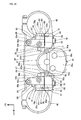
- FIG. 10 is a view when the handlebar clampers 61 and the top bridge 36 are viewed from the upper side in the axial direction of the steering shaft 38.
- the bracket 96 and so forth are removed for the convenience of illustration.
- the third female threaded portion 89a provided at a front end portion of the upper face 89 is disposed such that it overlaps with a shank 76a of a clamp bolt 76 in the vehicle widthwise direction but is offset forwardly from the shank 76a of the clamp bolt 76 in the forward and rearward direction.
- the third female threaded portion 89b disposed behind the third female threaded portion 89a is disposed such that it overlaps with the shank 76a of the clamp bolt 76 in the forward and rearward direction but is offset to the inner side with respect to the shank 76a in the vehicle widthwise direction.
- the third female threaded portions 89a and 89b are disposed in an offset relationship with respect to the shank 76a in this manner, the third female threaded portions 89a and 89b can be provided at a position at which they overlap with the shank 76a in the heightwise direction and can be disposed at a lower position. Therefore, the bracket 96 and so forth can be disposed at a lower position, and the electric part 98 can be prevented from interfering with the occupant.
- a handlebar fixing structure including a steering system 35 for steerably supporting a front wheel 2, which is attached for steering to a front portion of a vehicle body, on the vehicle body, a handlebar 30 attached above the steering system 35 and extending in a vehicle widthwise direction, handlebar posts 60 supported above the steering system 35 and supporting the handlebar 30 thereon, and handlebar clampers 61 attached to the handlebar posts 60 for fixing the handlebar 30 to the handlebar posts 60, the handlebar clampers 61 including a first clamper member 81 and a second clamper member 82 disposed across cylindrical portions 71 which are tip end portions of the handlebar posts 60 and the handlebar 30 from a direction orthogonal to the vehicle widthwise direction, elastic members 72 being interposed between the first clamper member 81 and the handlebar posts 60 and between the second clamper member 82 and the handlebar posts 60, the first clamper member 81 and the second clamper member 82 being coupled with each other by a fixing bolt 59 and having
- the handlebar 30 since the handlebar 30 is fixed to the handlebar clampers 61 disposed so as to sandwich the tip end portion of the handlebar posts 60, the handlebar 30 can be attached to a high position and the handlebar clampers 61 can be elastically supported by the elastic members 72 between the handlebar posts 60 and the first clamper member 81 and between the handlebar posts 60 and the second clamper member 82. Consequently, the handlebar fixing structure can be obtained which allows the handlebar 30 to be attached to a high position and besides has a high vibration absorbency.
- the abutting faces 86 and 93 are provided at a position at which the abutting faces 86 and 93 overlap with the fixing bolt 59 as viewed in the vehicle widthwise direction and are disposed on the opposite sides of the fixing bolt 59 in the vehicle widthwise direction. Therefore, the axial force of the fixing bolt 59 can be received effectively on the opposite sides in the vehicle widthwise direction in the proximity of the fixing bolt 59.
- the abutting faces 86 and 93 are bent as viewed in an axial direction of the fixing bolt 59. Therefore, the rigidity of the abutting faces 86 and 93 can be raised, and the axial force of the fixing bolt 59 can be received effectively.
- the first clamper member 81 includes a first female threaded portion 87a with which the fixing bolt 59 for fixing the first clamper member 81 and the second clamper member 82 to the handlebar post 60 is screwed and a second female threaded portion 84a with which a clamp bolt 76 for adjusting clamp load to the handlebar 30 is screwed, and third female threaded portions 89a and 89b for fixing an electric part 98 to the handlebar clamper 61 are provided at an upper portion of the first clamper member 81. Therefore, it is only necessary to perform machining of the female threaded portions 87a, 84a, 89a and 89b only for the first clamper member 81, and the handlebar clampers 61 can be manufactured readily. Further, the different part can be provided above the steering system 35 by a simple configuration making use of the third female threaded portions 89a and 89b.
- each of the handlebar post 60, the first clamper member 81 and the second clamper member 82 includes a pair of left and right parts, and a hydraulic chamber 46a of a damper apparatus main body 46 of a steering damper apparatus 45 is disposed between the left and right handlebar posts 60. Therefore, the steering damper apparatus 45 can be provided making use of the space between the left and right handlebar posts 60.
- the hydraulic chamber 46a is disposed below the handlebar 30. Therefore, the steering damper apparatus 45 can be provided making use of the space below the handlebar 30.
- the handlebar clamper 61 includes a lower fixing portion 75 fastened by the fixing bolt 59 and fixed to the handlebar post 60, an upper fixing portion 77 to which the clamp bolt 76 for adjusting clamp load to the handlebar 30 is fastened, and a handlebar fixing portion 78 provided between the upper fixing portion 77 and the lower fixing portion 75 and sandwiching the handlebar 30, and the elastic members 72 are fitted with the fixing bolt 59 and provided on the inner side of the lower fixing portion 75 while the abutting faces 86 and 93 are provided on the lower fixing portion 75.
- the handlebar clampers 61 can be elastically supported on the handlebar posts 60 through the elastic members 72 provided on the lower fixing portion 75 of the handlebar clampers 61 extending upwardly and downwardly, and the handlebar 30 can be fixed to the handlebar fixing portion 78 above the lower fixing portion 75. Consequently, the clamp load can be adjusted readily by the upper fixing portion 77.
- a fixing structure for a steering damper apparatus wherein the steering damper apparatus is disposed below a central portion of a handlebar in the leftward and rightward direction and is fastened and fixed to a handlebar post, which fixedly supports the handlebar thereon, by a bolt directed in the upward and downward direction (refer, for example, to a Patent Document: Japanese Patent Laid-Open No. 2006-224959 ).
- FIG. 11 is a view of the damper apparatus main body 46 as viewed from the lower side.
- FIG. 12 is a view of a fixing structure for the damper apparatus main body 46 as viewed from the upper side in the axial direction of the steering shaft 38.
- FIG. 13 is a view of the fixing structure for the damper apparatus main body 46 as viewed from the front side in the fastening direction of the stay fixing bolt 53.
- FIG. 14 is a view of the fixing structure for the damper apparatus main body 46 as viewed from the rear side in the fastening direction of the stay fixing bolt 53.
- the handlebar 30, post 64, steering shaft 38 and so forth are not depicted.
- the pivot shaft 46g of the damper apparatus main body 46 is provided at the center in the widthwise direction of a front portion of the case 46a.
- the case 46a defines a hydraulic chamber on the inner side thereof by wall portions thereof. Therefore, the case 46a can be regarded as a hydraulic chamber.
- the arm 46b is formed in a staircase pattern such that it is positioned downwardly toward the rear and includes an upper stage portion 110, a middle stage portion 111 and a lower stage portion 112.
- the upper stage portion 110 is connected to the pivot shaft 46g, and the middle stage portion 111 is positioned lower than the upper stage portion 110.
- the lower stage portion 112 is positioned lower than the middle stage portion 111 and connected to the pin 49.
- the arm 46b is fitted at the upper stage portion 110 thereof with the pivot shaft 46g and is integrally fixed to the pivot shaft 46g by an arm fixing nut 46h fastened to a lower end portion of the pivot shaft 46g.
- a pin connecting hole 112a is provided on the lower stage portion 112, and the pin 49 is inserted in the pin connecting hole 112a.
- connection portion 52 of the damper stay 47 is formed in an arc so as to prevent interference with an end portion of the upper stage portion 110 which moves along an arcuate locus.
- the female threaded portions 51a of the damper stay 47 extend substantially in parallel to the axial line 38a ( FIG. 3 ) of the steering shaft 38.
- the female threaded portions 51a and the case fixing bolts 50 fastened to the female threaded portions 51a extend upwardly and downwardly in a direction substantially orthogonal to the upper face of the top bridge 36.
- the outer side female threaded portions 51b of the damper stay 47 are provided on the outer sides of the female threaded portions 51a and extend substantially orthogonally to the axial line 38a.
- the outer side female threaded portions 51b and the stay fixing bolts 53 fastened to the outer side female threaded portions 51b extend forwardly and rearwardly in a direction substantially in parallel to the upper face of the top bridge 36.
- the stay fixing bolts 53 and the case fixing bolts 50 are disposed such that they overlap with each other in side elevation of the vehicle.
- FIG. 15 is a left side elevational view depicting a positional relationship between the damper apparatus main body 46 and the handlebar 30.
- the damper stay 47 is fixed to the case 46a in advance by the case fixing bolts 50 and integrated with the damper apparatus main body 46. Thereafter, the damper apparatus main body 46 passes from rearwardly between the straight portion 30a of the handlebar 30 and the upper face of the top bridge 36 until the fastening portions 51 are abutted with a rear face of the bracket portions 67 of the handlebar posts 60. Then, the damper apparatus main body 46 is fixed by the stay fixing bolts 53 inserted into the bracket portions 67 from the front.
- a tool path T (refer to FIGS. 1 and 15 ) which is a path along which a tool passes when the stay fixing bolts 53 are to be mounted or dismounted extends forwardly and rearwardly along the axial lines of the stay fixing bolts 53 in front of the stay fixing bolts 53.
- the tool path T extends forwardly and rearwardly substantially in parallel to the upper face of the top bridge 36 in front of the handlebar posts 60.
- the tool mentioned above is a bar-like tool which is fitted, for example, into an angular hole on the head of the stay fixing bolts 53.
- the case 46a since the case 46a is fixedly fastened to the handlebar posts 60 by the stay fixing bolts 53 directed in the forward and rearward direction, the space between the handlebar posts 60 and the meter 29 can be used as the tool path T. Therefore, the handlebar 30, electric part 98 or the like disposed above the case 46a does not interfere with the tool path T, and the stay fixing bolts 53 and the damper apparatus main body 46 can be mounted or dismounted and maintained readily.
- the case 46a can be disposed at a lower position. Therefore, the degree of freedom in disposition of the handlebar 30 in the upward and downward direction is high.
- the case 46a has at a front portion thereof the stepped portion 46e whose upper face is depressed by one stage, and the straight portion 30a is disposed above the stepped portion 46e. Therefore, the space of the stepped portion 46e can be utilized for disposition of the straight portion 30a, and the degree of freedom in disposition of the handlebar 30 in the upward and downward direction is high. Further, the capacity of the hydraulic chamber is assured sufficiently by a rear portion of the case 46a which is thicker upwardly and downwardly than the stepped portion 46e side.
- case fixing bolts 50 are disposed at a position at which they overlap with the straight portion 30a as viewed in the axial direction of the case fixing bolts 50, since they are fastened before the case 46a is fixed to the handlebar posts 60, the case fixing bolts 50 can be fastened readily.
- the straight portion 30a since the operation portions 46c and 46d of the upper face of the case 46a are disposed behind the straight portion 30a, the straight portion 30a does not interfere with the operation portions 46c and 46d, and the operation portions 46c and 46d can be operated readily.
- a steering damper fixing structure for a saddle type vehicle 1 including a steering system 35 for steerably supporting a front wheel 2, which is attached for steering to a front portion of a vehicle body, on the vehicle body, a handlebar 30 attached above the steering system 35 and extending in a vehicle widthwise direction, a pair of left and right handlebar posts 60 supported above the steering system 35 and supporting the handlebar 30 thereon, and a steering damper apparatus 45 including a case 46a supported for integral pivotal motion with the steering system 35 at a position between the left and right handlebar posts 60 at which the case 46a overlaps with the handlebar 30 as viewed in a direction of an axial line 38a of a steering shaft 38, wherein the case 46a is fastened to the steering system 35 by stay fixing bolts 53 directed in a forward and rearward direction.
- a part such as an electric part 98 which is positioned above the handlebar 30 or the steering damper apparatus 45 does not interfere with a tool path T for the stay fixing bolts 53. Therefore, the maintainability of the steering damper apparatus 45 and the degree of freedom in disposition of a different part can be improved.
- the pair of left and right handlebar posts 60 are configured independently of each other and the case 46a is fixed to a damper stay 47 fixed to and supported on each of the left and right handlebar posts 60, and the damper stay 47 is fastened to the handlebar posts 60 by the stay fixing bolts 53 directed in the forward and rearward direction. Therefore, even where the distance between the left and right handlebar posts 60 is changed, if only the damper stay 47 is changed in accordance with the change, then the case 46a can be fixed. Therefore, it is possible to easily cope with a change in setting of the left and right handlebar posts 60.
- each of the handlebar posts 60 includes a post 64 for supporting the handlebar 30 at the upper portion of the handlebar post 60 and a base 63 configured independently of the post 64 at a lower portion of the post 64, and a bracket portion 67 to which the case 46a is fastened is provided on the base 63 and the base unit 63 is fastened together with the post 64 to the steering system 35. Therefore, since the posts 64 having a function for supporting the handlebar 30 and the bracket portions 67 having a function for supporting the case 46a are separated from each other, it is possible to cope with a change in shape of the handlebar 30 and the case 46a individually. Therefore, the degree of freedom in change of setting is high. Further, since the posts 64 and the bases 63 are separate from each other, only the posts 64 can be mounted or dismounted while the case 46a remains fixed to the base 63. Therefore, the maintainability is high.
- stay fixing bolts 53 are disposed substantially in parallel to an upper face of a top bridge 36 of the steering system 35. Therefore, the stay fixing bolts 53 can be mounted and dismounted readily making use of the space along the upper face of the top bridge 36.
- the present invention is not limited to this, but it is only necessary for the steering system 35 to steer the front side traveling unit.
- the steering system 35 may steerably support a sled which is a front side traveling unit of a snow mobile.
- the present invention can be applied not only to a motorcycle but also to various vehicles such as a three-wheeled vehicle, a four-wheeled vehicle and a snow mobile.
- first female threaded portion 87a, second female threaded portion 84a and third female threaded portions 89a and 89b are provided on the first clamper member 81
- the present invention is not limited to this, but it is only necessary for the female threaded portions 87a, 84a, 89a and 89b to be provided collectively on one of the first clamper member 81 and the second clamper member 82.
- first female threaded portions 87a, 84a, 89a and 89b are provided on the second clamper member 82
- the fixing bolts 59 and the clamp bolts 76 may be inserted from the front side
- the female threaded portions 89a and 89b may be provided on an extension which extends rearwardly from an upper end portion of the second clamper member 82.
- bracket 96 is attached as a different part on the upper faces 89 of the first clamper members 81
- the type of the part to be attached to the upper faces 89 is not limited specifically.
- the electric part 98 is attached through the bracket 96 or the like, a part other than the electric part 98 may be attached.
- the handlebar post 60 includes two parts of the base 63 and the post 64, the base 63 and the post 64 may otherwise be formed as a unitary member.
- the handlebar post 60 may otherwise be provided integrally with the steering system 35 and may be provided, for example, integrally with the top bridge 36.
Landscapes
- Engineering & Computer Science (AREA)
- Mechanical Engineering (AREA)
- Steering Devices For Bicycles And Motorcycles (AREA)
Applications Claiming Priority (2)
| Application Number | Priority Date | Filing Date | Title |
|---|---|---|---|
| JP2014156201 | 2014-07-31 | ||
| JP2014187775A JP2016033002A (ja) | 2014-07-31 | 2014-09-16 | ハンドル固定構造 |
Publications (2)
| Publication Number | Publication Date |
|---|---|
| EP2979965A1 true EP2979965A1 (fr) | 2016-02-03 |
| EP2979965B1 EP2979965B1 (fr) | 2021-06-16 |
Family
ID=53491306
Family Applications (1)
| Application Number | Title | Priority Date | Filing Date |
|---|---|---|---|
| EP15173628.7A Active EP2979965B1 (fr) | 2014-07-31 | 2015-06-24 | Structure de fixation de guidon |
Country Status (6)
| Country | Link |
|---|---|
| US (1) | US9745017B2 (fr) |
| EP (1) | EP2979965B1 (fr) |
| JP (1) | JP2016033002A (fr) |
| CN (1) | CN105314042B (fr) |
| AU (1) | AU2015203151B2 (fr) |
| CA (1) | CA2895085C (fr) |
Cited By (3)
| Publication number | Priority date | Publication date | Assignee | Title |
|---|---|---|---|---|
| US20210323630A1 (en) * | 2020-04-21 | 2021-10-21 | Suzuki Motor Corporation | Handle |
| US20220268334A1 (en) * | 2021-02-24 | 2022-08-25 | Urmosi & Spaulding, LLC | Shock and vibration isolating handlebar mounting system |
| US11467011B2 (en) | 2018-03-28 | 2022-10-11 | Honda Motor Co., Ltd. | Support structure for meter stay |
Families Citing this family (3)
| Publication number | Priority date | Publication date | Assignee | Title |
|---|---|---|---|---|
| JP6578739B2 (ja) * | 2015-05-21 | 2019-09-25 | スズキ株式会社 | 操舵輪懸架装置 |
| CN107618605A (zh) * | 2017-10-17 | 2018-01-23 | 江苏振龙减震器有限公司 | 前叉肩盖 |
| DE102019101612A1 (de) * | 2019-01-23 | 2020-07-23 | Bayerische Motoren Werke Aktiengesellschaft | Kippentkoppelte Lenkvorrichtung eines Motorrades |
Citations (8)
| Publication number | Priority date | Publication date | Assignee | Title |
|---|---|---|---|---|
| US2396041A (en) * | 1944-12-21 | 1946-03-05 | Indian Motocycle Company | Resilient mounting for handle bars |
| US6332625B1 (en) * | 1999-03-31 | 2001-12-25 | Honda Giken Kogyo Kabushiki Kaisha | Steering system for a motorcycle |
| EP0981476B1 (fr) * | 1997-03-05 | 2003-05-28 | Supima Holdings Inc. | Structure de montage pour guidon de bicyclette |
| US6953201B1 (en) * | 2003-05-14 | 2005-10-11 | Vandemortel Dennis R | Cycle handlebar shock and vibration damper |
| JP2006224959A (ja) | 2005-02-17 | 2006-08-31 | Ralph S Norman | 遠隔制御装置を備えた流体スタビライザー |
| FR2899867A1 (fr) * | 2006-04-14 | 2007-10-19 | Lagar Concept Sarl | Dispositif pour la filtration des vibrations et des chocs sur un guidon de vehicule |
| JP2012144145A (ja) | 2011-01-12 | 2012-08-02 | Honda Motor Co Ltd | 鞍乗型車両のハンドル支持構造 |
| FR2983823A1 (fr) * | 2007-09-14 | 2013-06-14 | Neken | Guidon pour un vehicule |
Family Cites Families (22)
| Publication number | Priority date | Publication date | Assignee | Title |
|---|---|---|---|---|
| US5310203A (en) * | 1992-12-03 | 1994-05-10 | Chen Tsai L | Bicycle shock-absorbing apparatus |
| JPH0899676A (ja) * | 1994-09-30 | 1996-04-16 | Suzuki Motor Corp | 跨乗型車両のハンドルバー取付装置 |
| US6017047A (en) * | 1997-04-28 | 2000-01-25 | Hoose; Howard | Vehicle suspension |
| EP1265781A1 (fr) * | 2000-03-15 | 2002-12-18 | Sram Corporation | Systeme de commande integre pour vehicules a direction par guidon |
| US6712541B1 (en) * | 2000-12-05 | 2004-03-30 | Research Group Three Inc. | Multi-post shock absorber clamp system |
| US6802519B2 (en) * | 2002-09-09 | 2004-10-12 | Rtt Motorsports, Llc | Steering damper |
| US7131350B2 (en) * | 2003-03-25 | 2006-11-07 | Jas. D. Easton, Inc. | Bicycle stem with stress reducing handlebar clamp |
| US7111700B2 (en) * | 2003-07-31 | 2006-09-26 | Motoczysz Llc | Coaxial steering and suspension for motorcycle |
| EP1544093B1 (fr) * | 2003-12-16 | 2008-09-10 | Ducati Motor Holding S.p.A. | Suspension de roue avant pour motocyclette |
| US7118302B1 (en) * | 2004-04-14 | 2006-10-10 | Oberg Industries | Vehicle clamp having a vibration dampening insert |
| DE102004046158B4 (de) * | 2004-09-23 | 2006-07-27 | Gröbner Fertigungs GmbH | Vorrichtung zur Halterung eines Lenkers |
| WO2007092413A2 (fr) * | 2006-02-06 | 2007-08-16 | Motoczysz Llc (An Oregon Limited Liability Company) | Suspension laterale avant |
| US7832752B2 (en) * | 2006-02-06 | 2010-11-16 | Motoczysz Llc | Front end lateral suspension |
| JP4414445B2 (ja) * | 2007-04-06 | 2010-02-10 | 株式会社ホンダアクセス | 自動二輪車における電気機器取り付け構造 |
| JP5320162B2 (ja) * | 2009-05-22 | 2013-10-23 | 本田技研工業株式会社 | 車両用ステアリング装置 |
| FR2953482B1 (fr) * | 2009-12-03 | 2012-03-30 | S T W M | Systeme de bridage pour une fourche a suspension de vehicule. |
| US8317214B2 (en) * | 2010-03-30 | 2012-11-27 | George John Athanasiou | Shock and vibration damping handlebar mounting assembly |
| US8490996B2 (en) * | 2011-05-31 | 2013-07-23 | Ryan Ferguson | Shock-absorbing handlebar mount |
| EP2740658A1 (fr) * | 2012-03-02 | 2014-06-11 | Honda Motor Co., Ltd. | Véhicule de type à selle |
| FR2994934A1 (fr) * | 2012-09-06 | 2014-03-07 | Sarl Delta Usinage | Ensemble de tes d'un systeme de suspension avant d'une motocyclette |
| EP2899109B1 (fr) * | 2012-09-24 | 2018-04-11 | Yamaha Hatsudoki Kabushiki Kaisha | Véhicule |
| US10494050B2 (en) * | 2014-12-01 | 2019-12-03 | Radio Flyer Inc. | Steering mechanism for scooter |
-
2014
- 2014-09-16 JP JP2014187775A patent/JP2016033002A/ja active Pending
-
2015
- 2015-06-12 AU AU2015203151A patent/AU2015203151B2/en not_active Ceased
- 2015-06-19 CA CA2895085A patent/CA2895085C/fr not_active Expired - Fee Related
- 2015-06-24 EP EP15173628.7A patent/EP2979965B1/fr active Active
- 2015-07-16 US US14/800,967 patent/US9745017B2/en not_active Expired - Fee Related
- 2015-07-28 CN CN201510452564.3A patent/CN105314042B/zh not_active Expired - Fee Related
Patent Citations (9)
| Publication number | Priority date | Publication date | Assignee | Title |
|---|---|---|---|---|
| US2396041A (en) * | 1944-12-21 | 1946-03-05 | Indian Motocycle Company | Resilient mounting for handle bars |
| EP0981476B1 (fr) * | 1997-03-05 | 2003-05-28 | Supima Holdings Inc. | Structure de montage pour guidon de bicyclette |
| US6332625B1 (en) * | 1999-03-31 | 2001-12-25 | Honda Giken Kogyo Kabushiki Kaisha | Steering system for a motorcycle |
| US6953201B1 (en) * | 2003-05-14 | 2005-10-11 | Vandemortel Dennis R | Cycle handlebar shock and vibration damper |
| JP2006224959A (ja) | 2005-02-17 | 2006-08-31 | Ralph S Norman | 遠隔制御装置を備えた流体スタビライザー |
| EP2261527A2 (fr) * | 2005-02-17 | 2010-12-15 | Ralph S. Norman | Stabilisateur amortissant à fluide |
| FR2899867A1 (fr) * | 2006-04-14 | 2007-10-19 | Lagar Concept Sarl | Dispositif pour la filtration des vibrations et des chocs sur un guidon de vehicule |
| FR2983823A1 (fr) * | 2007-09-14 | 2013-06-14 | Neken | Guidon pour un vehicule |
| JP2012144145A (ja) | 2011-01-12 | 2012-08-02 | Honda Motor Co Ltd | 鞍乗型車両のハンドル支持構造 |
Cited By (6)
| Publication number | Priority date | Publication date | Assignee | Title |
|---|---|---|---|---|
| US11467011B2 (en) | 2018-03-28 | 2022-10-11 | Honda Motor Co., Ltd. | Support structure for meter stay |
| DE102019106809B4 (de) | 2018-03-28 | 2023-04-27 | Honda Motor Co., Ltd. | Haltestruktur für Instrumentenstütze |
| US20210323630A1 (en) * | 2020-04-21 | 2021-10-21 | Suzuki Motor Corporation | Handle |
| US11584472B2 (en) * | 2020-04-21 | 2023-02-21 | Suzuki Motor Corporation | Handle |
| US20220268334A1 (en) * | 2021-02-24 | 2022-08-25 | Urmosi & Spaulding, LLC | Shock and vibration isolating handlebar mounting system |
| US11608870B2 (en) * | 2021-02-24 | 2023-03-21 | Urmosi & Spaulding, LLC | Shock and vibration isolating handlebar mounting system |
Also Published As
| Publication number | Publication date |
|---|---|
| AU2015203151A1 (en) | 2016-02-18 |
| EP2979965B1 (fr) | 2021-06-16 |
| JP2016033002A (ja) | 2016-03-10 |
| CA2895085A1 (fr) | 2016-01-31 |
| CA2895085C (fr) | 2018-02-27 |
| US20160031520A1 (en) | 2016-02-04 |
| CN105314042A (zh) | 2016-02-10 |
| US9745017B2 (en) | 2017-08-29 |
| AU2015203151B2 (en) | 2016-10-06 |
| CN105314042B (zh) | 2018-06-22 |
Similar Documents
| Publication | Publication Date | Title |
|---|---|---|
| EP2979965B1 (fr) | Structure de fixation de guidon | |
| CN106560395B (zh) | 动力辅助自行车 | |
| JP6404308B2 (ja) | 鞍乗型車両 | |
| JP6187919B2 (ja) | 鞍乗型車両の操舵装置 | |
| US10131399B2 (en) | Positioning structure for front wheel suspension device | |
| CN108025793B (zh) | 鞍乘型车辆和前后联动制动机构 | |
| JP6837463B2 (ja) | 鞍乗り型車両 | |
| JP6222707B2 (ja) | 鞍乗型車両の操舵装置 | |
| JP6178822B2 (ja) | 鞍乗り型車両のステアリング構造 | |
| CN108025720B (zh) | 鞍乘型车辆 | |
| JP6206819B2 (ja) | 鞍乗型車両の操舵装置 | |
| JP5570376B2 (ja) | 鞍乗型乗物のステップステー構造 | |
| WO2018159014A1 (fr) | Structure de fixation de compteur pour véhicule à selle | |
| CN110035948A (zh) | 一种带有同步制动系统的两轮车辆 | |
| JP6313689B2 (ja) | 鞍乗り型の車両のステアリングダンパ固定構造 | |
| JP4091635B2 (ja) | 鞍乗型車両 | |
| JP2012206537A (ja) | 自動二輪車のフットレスト構造 | |
| JP6206818B2 (ja) | 鞍乗型車両の操舵装置 | |
| JP5916923B2 (ja) | 自動二輪車のフットレスト構造 | |
| JP6609169B2 (ja) | 鞍乗型乗物 | |
| WO2011001444A2 (fr) | Ensemble amortisseur de vibrations | |
| JPWO2019049466A1 (ja) | 鞍乗り型車両の前部構造 | |
| WO2019092745A1 (fr) | Sol d'un véhicule à deux roues | |
| JP2011173495A (ja) | 鞍乗り型車両の表示装置取付構造 | |
| JP2016064748A (ja) | 鞍乗型車両のセンタースタンド構造 |
Legal Events
| Date | Code | Title | Description |
|---|---|---|---|
| PUAI | Public reference made under article 153(3) epc to a published international application that has entered the european phase |
Free format text: ORIGINAL CODE: 0009012 |
|
| 17P | Request for examination filed |
Effective date: 20150624 |
|
| AK | Designated contracting states |
Kind code of ref document: A1 Designated state(s): AL AT BE BG CH CY CZ DE DK EE ES FI FR GB GR HR HU IE IS IT LI LT LU LV MC MK MT NL NO PL PT RO RS SE SI SK SM TR |
|
| AX | Request for extension of the european patent |
Extension state: BA ME |
|
| STAA | Information on the status of an ep patent application or granted ep patent |
Free format text: STATUS: EXAMINATION IS IN PROGRESS |
|
| 17Q | First examination report despatched |
Effective date: 20170403 |
|
| RIC1 | Information provided on ipc code assigned before grant |
Ipc: B62K 21/08 20060101AFI20201209BHEP Ipc: B62K 11/14 20060101ALI20201209BHEP Ipc: B62K 21/20 20060101ALI20201209BHEP |
|
| GRAP | Despatch of communication of intention to grant a patent |
Free format text: ORIGINAL CODE: EPIDOSNIGR1 |
|
| STAA | Information on the status of an ep patent application or granted ep patent |
Free format text: STATUS: GRANT OF PATENT IS INTENDED |
|
| INTG | Intention to grant announced |
Effective date: 20210120 |
|
| GRAS | Grant fee paid |
Free format text: ORIGINAL CODE: EPIDOSNIGR3 |
|
| GRAA | (expected) grant |
Free format text: ORIGINAL CODE: 0009210 |
|
| STAA | Information on the status of an ep patent application or granted ep patent |
Free format text: STATUS: THE PATENT HAS BEEN GRANTED |
|
| AK | Designated contracting states |
Kind code of ref document: B1 Designated state(s): AL AT BE BG CH CY CZ DE DK EE ES FI FR GB GR HR HU IE IS IT LI LT LU LV MC MK MT NL NO PL PT RO RS SE SI SK SM TR |
|
| REG | Reference to a national code |
Ref country code: GB Ref legal event code: FG4D |
|
| REG | Reference to a national code |
Ref country code: CH Ref legal event code: EP |
|
| REG | Reference to a national code |
Ref country code: DE Ref legal event code: R096 Ref document number: 602015070384 Country of ref document: DE |
|
| REG | Reference to a national code |
Ref country code: AT Ref legal event code: REF Ref document number: 1402126 Country of ref document: AT Kind code of ref document: T Effective date: 20210715 |
|
| REG | Reference to a national code |
Ref country code: IE Ref legal event code: FG4D |
|
| REG | Reference to a national code |
Ref country code: LT Ref legal event code: MG9D |
|
| PG25 | Lapsed in a contracting state [announced via postgrant information from national office to epo] |
Ref country code: FI Free format text: LAPSE BECAUSE OF FAILURE TO SUBMIT A TRANSLATION OF THE DESCRIPTION OR TO PAY THE FEE WITHIN THE PRESCRIBED TIME-LIMIT Effective date: 20210616 Ref country code: LT Free format text: LAPSE BECAUSE OF FAILURE TO SUBMIT A TRANSLATION OF THE DESCRIPTION OR TO PAY THE FEE WITHIN THE PRESCRIBED TIME-LIMIT Effective date: 20210616 Ref country code: BG Free format text: LAPSE BECAUSE OF FAILURE TO SUBMIT A TRANSLATION OF THE DESCRIPTION OR TO PAY THE FEE WITHIN THE PRESCRIBED TIME-LIMIT Effective date: 20210916 Ref country code: HR Free format text: LAPSE BECAUSE OF FAILURE TO SUBMIT A TRANSLATION OF THE DESCRIPTION OR TO PAY THE FEE WITHIN THE PRESCRIBED TIME-LIMIT Effective date: 20210616 |
|
| REG | Reference to a national code |
Ref country code: AT Ref legal event code: MK05 Ref document number: 1402126 Country of ref document: AT Kind code of ref document: T Effective date: 20210616 |
|
| REG | Reference to a national code |
Ref country code: NL Ref legal event code: MP Effective date: 20210616 |
|
| PG25 | Lapsed in a contracting state [announced via postgrant information from national office to epo] |
Ref country code: NO Free format text: LAPSE BECAUSE OF FAILURE TO SUBMIT A TRANSLATION OF THE DESCRIPTION OR TO PAY THE FEE WITHIN THE PRESCRIBED TIME-LIMIT Effective date: 20210916 Ref country code: RS Free format text: LAPSE BECAUSE OF FAILURE TO SUBMIT A TRANSLATION OF THE DESCRIPTION OR TO PAY THE FEE WITHIN THE PRESCRIBED TIME-LIMIT Effective date: 20210616 Ref country code: SE Free format text: LAPSE BECAUSE OF FAILURE TO SUBMIT A TRANSLATION OF THE DESCRIPTION OR TO PAY THE FEE WITHIN THE PRESCRIBED TIME-LIMIT Effective date: 20210616 Ref country code: GR Free format text: LAPSE BECAUSE OF FAILURE TO SUBMIT A TRANSLATION OF THE DESCRIPTION OR TO PAY THE FEE WITHIN THE PRESCRIBED TIME-LIMIT Effective date: 20210917 Ref country code: LV Free format text: LAPSE BECAUSE OF FAILURE TO SUBMIT A TRANSLATION OF THE DESCRIPTION OR TO PAY THE FEE WITHIN THE PRESCRIBED TIME-LIMIT Effective date: 20210616 |
|
| PG25 | Lapsed in a contracting state [announced via postgrant information from national office to epo] |
Ref country code: AT Free format text: LAPSE BECAUSE OF FAILURE TO SUBMIT A TRANSLATION OF THE DESCRIPTION OR TO PAY THE FEE WITHIN THE PRESCRIBED TIME-LIMIT Effective date: 20210616 Ref country code: ES Free format text: LAPSE BECAUSE OF FAILURE TO SUBMIT A TRANSLATION OF THE DESCRIPTION OR TO PAY THE FEE WITHIN THE PRESCRIBED TIME-LIMIT Effective date: 20210616 Ref country code: NL Free format text: LAPSE BECAUSE OF FAILURE TO SUBMIT A TRANSLATION OF THE DESCRIPTION OR TO PAY THE FEE WITHIN THE PRESCRIBED TIME-LIMIT Effective date: 20210616 Ref country code: PT Free format text: LAPSE BECAUSE OF FAILURE TO SUBMIT A TRANSLATION OF THE DESCRIPTION OR TO PAY THE FEE WITHIN THE PRESCRIBED TIME-LIMIT Effective date: 20211018 Ref country code: RO Free format text: LAPSE BECAUSE OF FAILURE TO SUBMIT A TRANSLATION OF THE DESCRIPTION OR TO PAY THE FEE WITHIN THE PRESCRIBED TIME-LIMIT Effective date: 20210616 Ref country code: SM Free format text: LAPSE BECAUSE OF FAILURE TO SUBMIT A TRANSLATION OF THE DESCRIPTION OR TO PAY THE FEE WITHIN THE PRESCRIBED TIME-LIMIT Effective date: 20210616 Ref country code: SK Free format text: LAPSE BECAUSE OF FAILURE TO SUBMIT A TRANSLATION OF THE DESCRIPTION OR TO PAY THE FEE WITHIN THE PRESCRIBED TIME-LIMIT Effective date: 20210616 Ref country code: EE Free format text: LAPSE BECAUSE OF FAILURE TO SUBMIT A TRANSLATION OF THE DESCRIPTION OR TO PAY THE FEE WITHIN THE PRESCRIBED TIME-LIMIT Effective date: 20210616 Ref country code: CZ Free format text: LAPSE BECAUSE OF FAILURE TO SUBMIT A TRANSLATION OF THE DESCRIPTION OR TO PAY THE FEE WITHIN THE PRESCRIBED TIME-LIMIT Effective date: 20210616 |
|
| REG | Reference to a national code |
Ref country code: CH Ref legal event code: PL |
|
| REG | Reference to a national code |
Ref country code: DE Ref legal event code: R084 Ref document number: 602015070384 Country of ref document: DE |
|
| PG25 | Lapsed in a contracting state [announced via postgrant information from national office to epo] |
Ref country code: PL Free format text: LAPSE BECAUSE OF FAILURE TO SUBMIT A TRANSLATION OF THE DESCRIPTION OR TO PAY THE FEE WITHIN THE PRESCRIBED TIME-LIMIT Effective date: 20210616 |
|
| REG | Reference to a national code |
Ref country code: BE Ref legal event code: MM Effective date: 20210630 |
|
| REG | Reference to a national code |
Ref country code: DE Ref legal event code: R097 Ref document number: 602015070384 Country of ref document: DE |
|
| PG25 | Lapsed in a contracting state [announced via postgrant information from national office to epo] |
Ref country code: MC Free format text: LAPSE BECAUSE OF FAILURE TO SUBMIT A TRANSLATION OF THE DESCRIPTION OR TO PAY THE FEE WITHIN THE PRESCRIBED TIME-LIMIT Effective date: 20210616 Ref country code: LU Free format text: LAPSE BECAUSE OF NON-PAYMENT OF DUE FEES Effective date: 20210624 |
|
| PLBE | No opposition filed within time limit |
Free format text: ORIGINAL CODE: 0009261 |
|
| STAA | Information on the status of an ep patent application or granted ep patent |
Free format text: STATUS: NO OPPOSITION FILED WITHIN TIME LIMIT |
|
| PG25 | Lapsed in a contracting state [announced via postgrant information from national office to epo] |
Ref country code: LI Free format text: LAPSE BECAUSE OF NON-PAYMENT OF DUE FEES Effective date: 20210630 Ref country code: IE Free format text: LAPSE BECAUSE OF NON-PAYMENT OF DUE FEES Effective date: 20210624 Ref country code: DK Free format text: LAPSE BECAUSE OF FAILURE TO SUBMIT A TRANSLATION OF THE DESCRIPTION OR TO PAY THE FEE WITHIN THE PRESCRIBED TIME-LIMIT Effective date: 20210616 Ref country code: CH Free format text: LAPSE BECAUSE OF NON-PAYMENT OF DUE FEES Effective date: 20210630 |
|
| 26N | No opposition filed |
Effective date: 20220317 |
|
| GBPC | Gb: european patent ceased through non-payment of renewal fee |
Effective date: 20210916 |
|
| PG25 | Lapsed in a contracting state [announced via postgrant information from national office to epo] |
Ref country code: AL Free format text: LAPSE BECAUSE OF FAILURE TO SUBMIT A TRANSLATION OF THE DESCRIPTION OR TO PAY THE FEE WITHIN THE PRESCRIBED TIME-LIMIT Effective date: 20210616 |
|
| PG25 | Lapsed in a contracting state [announced via postgrant information from national office to epo] |
Ref country code: IT Free format text: LAPSE BECAUSE OF FAILURE TO SUBMIT A TRANSLATION OF THE DESCRIPTION OR TO PAY THE FEE WITHIN THE PRESCRIBED TIME-LIMIT Effective date: 20210616 Ref country code: GB Free format text: LAPSE BECAUSE OF NON-PAYMENT OF DUE FEES Effective date: 20210916 Ref country code: FR Free format text: LAPSE BECAUSE OF NON-PAYMENT OF DUE FEES Effective date: 20210816 Ref country code: BE Free format text: LAPSE BECAUSE OF NON-PAYMENT OF DUE FEES Effective date: 20210630 |
|
| PG25 | Lapsed in a contracting state [announced via postgrant information from national office to epo] |
Ref country code: HU Free format text: LAPSE BECAUSE OF FAILURE TO SUBMIT A TRANSLATION OF THE DESCRIPTION OR TO PAY THE FEE WITHIN THE PRESCRIBED TIME-LIMIT; INVALID AB INITIO Effective date: 20150624 |
|
| PG25 | Lapsed in a contracting state [announced via postgrant information from national office to epo] |
Ref country code: CY Free format text: LAPSE BECAUSE OF FAILURE TO SUBMIT A TRANSLATION OF THE DESCRIPTION OR TO PAY THE FEE WITHIN THE PRESCRIBED TIME-LIMIT Effective date: 20210616 |
|
| PGFP | Annual fee paid to national office [announced via postgrant information from national office to epo] |
Ref country code: DE Payment date: 20230502 Year of fee payment: 9 |
|
| PG25 | Lapsed in a contracting state [announced via postgrant information from national office to epo] |
Ref country code: MK Free format text: LAPSE BECAUSE OF FAILURE TO SUBMIT A TRANSLATION OF THE DESCRIPTION OR TO PAY THE FEE WITHIN THE PRESCRIBED TIME-LIMIT Effective date: 20210616 |
|
| PG25 | Lapsed in a contracting state [announced via postgrant information from national office to epo] |
Ref country code: MT Free format text: LAPSE BECAUSE OF FAILURE TO SUBMIT A TRANSLATION OF THE DESCRIPTION OR TO PAY THE FEE WITHIN THE PRESCRIBED TIME-LIMIT Effective date: 20210616 |