EP2975999B1 - Intravascular optical imaging system - Google Patents
Intravascular optical imaging system Download PDFInfo
- Publication number
- EP2975999B1 EP2975999B1 EP14710881.5A EP14710881A EP2975999B1 EP 2975999 B1 EP2975999 B1 EP 2975999B1 EP 14710881 A EP14710881 A EP 14710881A EP 2975999 B1 EP2975999 B1 EP 2975999B1
- Authority
- EP
- European Patent Office
- Prior art keywords
- catheter
- imaging
- imaging system
- optical
- cardiac
- Prior art date
- Legal status (The legal status is an assumption and is not a legal conclusion. Google has not performed a legal analysis and makes no representation as to the accuracy of the status listed.)
- Active
Links
Images


Classifications
-
- A—HUMAN NECESSITIES
- A61—MEDICAL OR VETERINARY SCIENCE; HYGIENE
- A61B—DIAGNOSIS; SURGERY; IDENTIFICATION
- A61B5/00—Measuring for diagnostic purposes; Identification of persons
- A61B5/72—Signal processing specially adapted for physiological signals or for diagnostic purposes
- A61B5/7271—Specific aspects of physiological measurement analysis
- A61B5/7285—Specific aspects of physiological measurement analysis for synchronizing or triggering a physiological measurement or image acquisition with a physiological event or waveform, e.g. an ECG signal
-
- A—HUMAN NECESSITIES
- A61—MEDICAL OR VETERINARY SCIENCE; HYGIENE
- A61B—DIAGNOSIS; SURGERY; IDENTIFICATION
- A61B1/00—Instruments for performing medical examinations of the interior of cavities or tubes of the body by visual or photographical inspection, e.g. endoscopes; Illuminating arrangements therefor
- A61B1/00163—Optical arrangements
-
- A—HUMAN NECESSITIES
- A61—MEDICAL OR VETERINARY SCIENCE; HYGIENE
- A61B—DIAGNOSIS; SURGERY; IDENTIFICATION
- A61B5/00—Measuring for diagnostic purposes; Identification of persons
- A61B5/0059—Measuring for diagnostic purposes; Identification of persons using light, e.g. diagnosis by transillumination, diascopy, fluorescence
- A61B5/0062—Arrangements for scanning
- A61B5/0066—Optical coherence imaging
-
- A—HUMAN NECESSITIES
- A61—MEDICAL OR VETERINARY SCIENCE; HYGIENE
- A61B—DIAGNOSIS; SURGERY; IDENTIFICATION
- A61B5/00—Measuring for diagnostic purposes; Identification of persons
- A61B5/0059—Measuring for diagnostic purposes; Identification of persons using light, e.g. diagnosis by transillumination, diascopy, fluorescence
- A61B5/0073—Measuring for diagnostic purposes; Identification of persons using light, e.g. diagnosis by transillumination, diascopy, fluorescence by tomography, i.e. reconstruction of 3D images from 2D projections
-
- A—HUMAN NECESSITIES
- A61—MEDICAL OR VETERINARY SCIENCE; HYGIENE
- A61B—DIAGNOSIS; SURGERY; IDENTIFICATION
- A61B5/00—Measuring for diagnostic purposes; Identification of persons
- A61B5/0059—Measuring for diagnostic purposes; Identification of persons using light, e.g. diagnosis by transillumination, diascopy, fluorescence
- A61B5/0082—Measuring for diagnostic purposes; Identification of persons using light, e.g. diagnosis by transillumination, diascopy, fluorescence adapted for particular medical purposes
- A61B5/0084—Measuring for diagnostic purposes; Identification of persons using light, e.g. diagnosis by transillumination, diascopy, fluorescence adapted for particular medical purposes for introduction into the body, e.g. by catheters
-
- A—HUMAN NECESSITIES
- A61—MEDICAL OR VETERINARY SCIENCE; HYGIENE
- A61B—DIAGNOSIS; SURGERY; IDENTIFICATION
- A61B5/00—Measuring for diagnostic purposes; Identification of persons
- A61B5/02—Detecting, measuring or recording for evaluating the cardiovascular system, e.g. pulse, heart rate, blood pressure or blood flow
- A61B5/02007—Evaluating blood vessel condition, e.g. elasticity, compliance
-
- A—HUMAN NECESSITIES
- A61—MEDICAL OR VETERINARY SCIENCE; HYGIENE
- A61B—DIAGNOSIS; SURGERY; IDENTIFICATION
- A61B5/00—Measuring for diagnostic purposes; Identification of persons
- A61B5/02—Detecting, measuring or recording for evaluating the cardiovascular system, e.g. pulse, heart rate, blood pressure or blood flow
- A61B5/0205—Simultaneously evaluating both cardiovascular conditions and different types of body conditions, e.g. heart and respiratory condition
-
- A—HUMAN NECESSITIES
- A61—MEDICAL OR VETERINARY SCIENCE; HYGIENE
- A61B—DIAGNOSIS; SURGERY; IDENTIFICATION
- A61B5/00—Measuring for diagnostic purposes; Identification of persons
- A61B5/24—Detecting, measuring or recording bioelectric or biomagnetic signals of the body or parts thereof
- A61B5/316—Modalities, i.e. specific diagnostic methods
- A61B5/318—Heart-related electrical modalities, e.g. electrocardiography [ECG]
- A61B5/346—Analysis of electrocardiograms
- A61B5/349—Detecting specific parameters of the electrocardiograph cycle
- A61B5/355—Detecting T-waves
-
- A—HUMAN NECESSITIES
- A61—MEDICAL OR VETERINARY SCIENCE; HYGIENE
- A61B—DIAGNOSIS; SURGERY; IDENTIFICATION
- A61B5/00—Measuring for diagnostic purposes; Identification of persons
- A61B5/68—Arrangements of detecting, measuring or recording means, e.g. sensors, in relation to patient
- A61B5/6846—Arrangements of detecting, measuring or recording means, e.g. sensors, in relation to patient specially adapted to be brought in contact with an internal body part, i.e. invasive
- A61B5/6847—Arrangements of detecting, measuring or recording means, e.g. sensors, in relation to patient specially adapted to be brought in contact with an internal body part, i.e. invasive mounted on an invasive device
- A61B5/6852—Catheters
-
- A—HUMAN NECESSITIES
- A61—MEDICAL OR VETERINARY SCIENCE; HYGIENE
- A61B—DIAGNOSIS; SURGERY; IDENTIFICATION
- A61B5/00—Measuring for diagnostic purposes; Identification of persons
- A61B5/72—Signal processing specially adapted for physiological signals or for diagnostic purposes
- A61B5/7271—Specific aspects of physiological measurement analysis
- A61B5/7282—Event detection, e.g. detecting unique waveforms indicative of a medical condition
-
- A—HUMAN NECESSITIES
- A61—MEDICAL OR VETERINARY SCIENCE; HYGIENE
- A61B—DIAGNOSIS; SURGERY; IDENTIFICATION
- A61B7/00—Instruments for auscultation
-
- A—HUMAN NECESSITIES
- A61—MEDICAL OR VETERINARY SCIENCE; HYGIENE
- A61B—DIAGNOSIS; SURGERY; IDENTIFICATION
- A61B5/00—Measuring for diagnostic purposes; Identification of persons
- A61B5/02—Detecting, measuring or recording for evaluating the cardiovascular system, e.g. pulse, heart rate, blood pressure or blood flow
- A61B5/024—Measuring pulse rate or heart rate
-
- A—HUMAN NECESSITIES
- A61—MEDICAL OR VETERINARY SCIENCE; HYGIENE
- A61B—DIAGNOSIS; SURGERY; IDENTIFICATION
- A61B5/00—Measuring for diagnostic purposes; Identification of persons
- A61B5/68—Arrangements of detecting, measuring or recording means, e.g. sensors, in relation to patient
- A61B5/6846—Arrangements of detecting, measuring or recording means, e.g. sensors, in relation to patient specially adapted to be brought in contact with an internal body part, i.e. invasive
- A61B5/6867—Arrangements of detecting, measuring or recording means, e.g. sensors, in relation to patient specially adapted to be brought in contact with an internal body part, i.e. invasive specially adapted to be attached or implanted in a specific body part
- A61B5/6876—Blood vessel
Definitions
- the present invention relates to optical imaging systems for imaging internal structures of the human or animal body.
- the invention relates to imaging systems which can be used for intracoronary imaging.
- OCT optical coherence tomography
- an imaging light beam 1 emitted from a distal end 2 of a catheter 3 scans the wall 4 of the artery 5.
- the catheter 3 rotates about its own axis (as indicated by arrow 6) to continuously sweep the imaging light beam 1 in a rotary fashion through successive radial directions, and collects the back-reflected light, which carries information relating to the illuminated tissue.
- a coherence fringe signal of the back-reflected light is obtained by combining it with a reference light beam. The fringe signal is converted into an electronic signal, digitized, and stored.
- the coherence fringe signal data corresponding to each wavelength sweep of the laser is further processed by inverse Fourier transform.
- the data corresponding to each wavelength sweep after inverse Fourier transform forms an A-line.
- the rotational movement 6 of the catheter 3 enables A-lines to be generated for multiple radial directions each corresponding to a circumferential position on the artery thereby generating a 2D image of a cross section of the artery.
- Each 2D image of an artery cross section may be formed by approximately 500 lines or more, corresponding to a full circumferential (360°) scan by the catheter 3. This full circumferential scan may be referred to herein as a "frame".
- 3D imaging of the artery 5 may be achieved by longitudinal translational motion (as indicated by arrow 7) of the catheter 3 along the artery 5 (also referred to herein as "pulling back" the catheter) while the catheter is rotating.
- the catheter scan will thereby sweep out a helical path of successive A-lines to form the full 3D dataset.
- Each 360 degree rotation within the helical path may also be referred to as a frame, and multiple frames are generated along the longitudinal (z) axis.
- a problem which has been found to arise in coronary imaging is that of motion artefact in which the images generated are sub-optimal caused by movement of the artery during scanning. It is an object of the present invention to avoid or at least mitigate problems arising from motion artefact and thereby improve image quality.
- US 5321501 describes a probe for imaging tubular structures such as blood vessels, having an optical fiber embedded in an inner sheath rotatably mounted in an outer sheath.
- the inner sheath has a lens at the distal end of the fiber and terminates in an angled mirrored surface which extends beyond the end of the outer sheath.
- US 5740808 describes a catheter tube carrying an imaging element to visualize tissue.
- a stepper motor is gated by a gating circuit to the QRS of an electrocardiogram taken simultaneously with image gathering so that data image slices are recorded in axial increments at either end-diastolic or end-systolic points of the heart beat.
- the present invention provides a catheter-based optical imaging system for imaging a patient according to claim 1. Further embodiments of the present invention are defined by the dependent claims.
- At least one aspect of motion artefact is caused by the strong movement of the heart during the systolic phase of the heart cycle.
- This phase can be recognized in the electrocardiogram (ECG) by the R-peak and subsequent S- and T-waves.
- ECG electrocardiogram
- the cardiac motion during acquisition will cause inaccuracy in frame spacing and possibly frame order, due to motion of the catheter along the vessel. This can compromise the fidelity of the longitudinal rendering and the 3D visualization of the data.
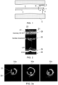
- the deformation in the longitudinal image (along the artery) of a pullback data set due to cardiac motion is shown in figure 2.
- Figure 2 shows at 20 an image of a longitudinal section of coronary artery which includes a stent.
- the stent has a regular trellis-like framework of intersecting elements 21 which it can readily be seen have been rendered in the image in a somewhat irregular pattern which is particularly disrupted in a central location 22 which coincides with a large disturbance caused by cardiac movement, represented in image 23, and with left ventricular blood pressure represented at image 24 and with electrocardiogram wave data represented at image 25.
- FIG. 3a shows a series of three frames which provide three cross sections of the artery chronologically sequenced from a longitudinal scan (pullback) of the catheter.
- An edge of a stent 30 (apparent by the periodic structure 31) shows up in a first frame 32a, disappears in a second frame 32b and then reappears in the third frame 32c.
- cardiac motion causes the tissue wall to "overtake" the longitudinal motion of the catheter during pullback and the edge of the stent appears more than once in successive 2D images recorded during pullback.
- a pullback length may be 50-100 mm and the speed of pullback may be 20 mm/second.
- the motion artefact will show up more than once in such a pullback because the duration of a heart cycle is around 1 second in patients undergoing percutaneous coronary intervention (PCI).
- PCI percutaneous coronary intervention
- one solution is to increase the pullback speed of the catheter 3 so that the pullback procedure can be finished within one heart cycle.
- keeping the imaging speed e.g. the frame rate
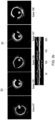
- simply increasing the pullback speed will aggravate the under-sampling along the artery as shown in figure 4 .
- FIG 4 a selection of OCT images is shown obtained under various pull-back speeds.
- Each image shows a view of a longitudinal segment of the artery in which lies a coronary stent having the visible trellis-like lattice structure.
- a close-up portion of each image is shown above it.
- Figure 4a shows a longitudinal segment 40a acquired using a pullback speed of 15 mm/sec (providing a longitudinal sampling interval of 0.9375 mm from 160 frames per second scan rate);
- Figure 4b shows a longitudinal segment 40b acquired using a pullback speed of 20 mm/sec (providing a longitudinal sampling interval of 0.125 mm from 160 frames per second scan rate);
- Figure 4c shows a longitudinal segment 40c acquired using a pullback speed of 30 mm/sec (providing a longitudinal sampling interval of 0.1875 mm from 160 frames per second scan rate);
- Figure 4d shows a longitudinal segment 40d acquired using a pullback speed of 40 mm/sec (providing a longitudinal sampling interval of 0.25 mm from 160 frames per second scan rate).
- each scan 40a, 40b, 40c, 40d is shown a corresponding ECG trace 42a, 42b, 42c, 42d which is aligned in time with the data acquisition time along the longitudinal (z) axis of the scan. It can be seen that each ECG pulse correlates closely with a motion artefact 41 indicated by the symbol #.
- the inset close-up images 43a, 43b, 43c, 43d also show the increasing levels of pixellation in the images caused by the increased speed of pullback.
- a further aspect of conducting artery imaging is that the blood is preferably flushed out of the artery with flush medium during imaging.
- the flush medium may be saline or x-ray contrast dye (e.g. Visipaque from GE Healthcare). These iodine-containing fluids are nephrotoxic and hence their use should be limited to a minimum. With a shorter imaging procedure, the flush volume can be further reduced.
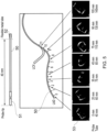
- a further aspect of conducting artery imaging is that of non-uniform rotation distortion.
- a conventional method to drive an OCT catheter is to rotate the inner components of the catheter by a proximal motor, i.e. a motor disposed towards a proximal end of the catheter 3 remote from the distal end 2 and the imaging tip. Because of the variable mechanical resistance along the curved catheter, the rotation speed of the distal tip may not be constant, leading to non-uniform rotation distortion (NURD).
- NURD non-uniform rotation distortion
- the catheter 50 has a probe tip 51 providing the imaging tip extending 40 mm out of a flexible metal tube 52.
- Each of the images 53 represents a cross-sectional image taken at a specified longitudinal distance along a square section phantom having varying curvature along its longitudinal extent. It can be seen that each section has varying degrees of distortion caused by non-uniform rotation caused by varying degrees of curvature of the vessel.
- One option for reducing or eliminating this effect is to provide rotation of the imaging tip by a local micro-motor at the distal end of the catheter powered by electrical leads extending the length of the catheter, as will be described in more detail later.
- Figure 6 shows a schematic diagram of a high-speed optical imaging system which is configured to complete imaging of an entire artery within one cardiac cycle while maintaining a small sampling pitch along the artery.
- the high-speed intravascular optical imaging system 60 for coronary imaging comprises an outer catheter 61 or transparent tube; an inner catheter 62 supporting an imaging device; a pullback system 63 coupled to the inner catheter 62 for providing longitudinal (z-direction) displacement of the imaging device; a high-speed frequency-scanning laser 64; an interferometer 65; a data acquisition system 66; and an electrocardiography trigger module 67. Also provided may be a display 11, control hardware and data storage such as computer 12.
- the pullback system may include a motor controller 68.
- the interferometer 65 includes optical paths comprising: a 2x2 coupler 13, a reference arm 14, a sample measurement arm 15 with polarization controller 16, and a 2x2 coupler 17 providing an output path from the reference and sample arms to a balanced photonics detector 18 and a digitizer 19.
- the operation of the interferometer may be according to known principles and need not be described further in great detail.
- a pullback speed of the imaging device effected by the pullback system 63 should be the length of the artery or artery segment for imaging divided by the duration of one cardiac cycle.
- the cardiac cycle of a healthy adult is typically 0.6 -1.0 second. Patients undergoing percutaneous coronary intervention may be given medication to slow the heart cycle to approximately 60 beats per minute, i.e. each cardiac cycle lasts 1 second in duration.
- the time period suitable for imaging is the time between the T-wave in the ECG and the R-wave in the next cardiac cycle. This period represents approximately 60-70% of the cardiac cycle.
- the relevant length of an artery for imaging is typically 60 - 80 mm although it may be longer, particularly in the right coronary artery.
- Imaging a length of artery of 70 mm in 0.7 sec requires pullback speed of 100 mm/sec.
- Typical commercial OCT systems use a frame pitch (longitudinal sampling interval) of maximally 250 ⁇ m.
- a high-speed pullback at this pitch requires a frame rate of 400 frames/sec, meaning that the imaging device must be rotated at 400 revolutions per second (rps).
- the swept scanning rate of the laser must be greater than 200 kHz.
- a limitation of current intravascular OCT scanners is the limited longitudinal sampling.
- the width of the focus created by catheter optics is about 30 ⁇ m, which is much smaller than the frame pitch.
- the system described in this specification can perform imaging of the relevant length of coronary artery (e.g. 60-80 mm) in less than one heart cycle with adequate longitudinal sampling.
- a frame pitch of 30 ⁇ m and 100 mm/s pullback speed a frame rate of 3.3 kHz is required, and a laser sweep rate of 1.65 MHz.
- 1000 lines per frame are preferable. This can be achieved by a laser that sweeps at 3.3 MHz.
- the imaging probe 70 includes the outer catheter 61 which is a transparent tube suitable for the optical radiation from the laser 64 to pass through and a connector 75 and the inner catheter 62 which supports or contains the imaging device.
- the inner catheter 62 is coupled to the connector 75 providing as output the control wires 71 for connection to the motor control unit 68 and the optical fibre 72 forming part of the interferometer 65.
- the outer catheter 61 may include a distal tip 73 which includes a hole 74 for connecting to a guild wire or guide wire (not shown). Such a guide wire may be used to insert the outer catheter 61 into the artery.
- the imaging probe 70 is inserted into an artery to perform the scanning and the outer catheter 61 remains stationary within the artery while the imaging device supported in or on the inner catheter scans both rotationally about the inner catheter axis and longitudinally under the control of the pullback system to be further described later.
- FIG 8 shows a schematic diagram of detail of an exemplary imaging probe 80.
- the outer catheter 61 and inner catheter 62 are provided as tubes which are transparent at least to the wavelengths of optical radiation provided by the frequency-scanning laser 64, at least in the regions of the catheters where the optical radiation has to pass through the walls of the catheters.
- the distal end of the inner catheter or tube 62 houses a motor 81 having a motor output shaft 82 to which is mounted an optical element 83.
- Control wires 84 extend along the inner catheter from the proximal end to the motor 81 at the distal end, to provide power supply and control to the motor 81.
- the control wires 84 may be affixed to or embedded in the walls of the inner catheter 62.
- An optical fibre 85 extends along the inner catheter 62 from the proximal end to near the distal end at a position terminating at, or just short of, the optical element 83.
- the end of the optical fibre 85 may include a lens element 86 such as a ball lens or a gradient refractive index lens integrally formed with the fibre.
- the optical element 83 provides a reflective surface 87 configured to reflect light emerging from the fibre 85 / lens 86 along the axis of the fibre to an orthogonal (radial) direction where it passes through the inner and outer catheter walls to illuminate artery walls.
- the motor shaft 82 rotates, the optical element rotates about the longitudinal axis of the catheter causing the optical radiation to scan around the axis of the catheter in a circumferential scan (frame).
- the motor 81 is a synchronous motor which provides full circumferential scanning. It is also possible to provide oscillation scanning where the optical element 83 is oscillated about the catheter axis so that the optical radiation only describes part of a full circumference in the circumferential scan.
- FIG. 9 shows a schematic cross-sectional diagram of a synchronous micro-motor 90 suitable for implementing the motor 81.
- the synchronous micro-motor 90 comprises a permanent magnetic rotor 91, coils 92, bearings 93, shaft 94, control / power wires 95 and shield 96.
- the rotating speed of the synchronous micro-motor 90 is preferably ⁇ 400 revolutions per second. It is driven by a multi-phase sinusoidal current signal via the wires 95.
- the speed of the motor is synchronized to the frequency of the driving signal.
- the high rotating speed of the motor can be achieved by increasing the frequency of the driving signal from a lower number or from zero frequency.
- Figure 10 shows schematic perspective views of two different exemplary optical elements 83 and their relationship with the optical fibre 85 and lens 86.
- the optical elements 83 may be used to focus and deflect the light beam emerging from the fibre 85.
- the fibre 85 may include a GRIN lens or ball lens at the tip of a single mode fibre.
- the optical element 100 of figure 10a combines a reflecting prism or mirror with a concave reflecting surface to provide focusing, further focusing, defocusing, or further defocusing of the radially directed light beam 105, particularly to correct for astigmatism of the light beam.
- the optical element 101 of figure 10b combines a reflecting prism or mirror with a convex reflecting surface to provide focusing or further focusing of the radially directed light beam 105, particularly to correct for astigmatism of the light beam.
- the transverse resolution of the imaging probe can be improved with such an arrangement.
- the correction can be made along two optical axes by appropriate selection of concavity or convexity in two orthogonal directions.
- the optical element 83 can contain all the required focusing arrangements in one element. A separate lens arrangement at the end of the fibre can then be omitted, reducing the rigid length of the probe, i.e. the portion housing the motor, optics and fibre termination (the length from the emitting surface of the fiber to the distal end of the motor).
- the optical element 110 may comprise three interfaces - a first transmissive interface 111, a reflective surface 112 and a second transmissive interface 113. Reflective surface 112 is used for deflecting the beam.
- Transmissive interface 111 may include a curved surface (concave or convex - as shown at 111a) for optical coupling to the fibre 85.
- Transmissive interface 113 may include a curved surface (e.g. convex or concave as shown at 113a) for optimal focusing of the radially directed light beam 105 on the artery walls. Any of the three interfaces / surfaces 111, 112, 113 can be made into a curved surface to perform focusing and/or correction of astigmatism.
- the curved surfaces may be spherical surfaces for focusing.
- the optical element 110 is preferably a unitary structure. Providing all of the focusing optics in one element mounted directly to the motor shaft also provides a compact device and simpler, lower cost assembly and design.
- the connector 75 is used to collect the motor control wires 71 and optical fibre 72 from the proximal end of the inner catheter 62, to which it is connected.
- This connector 75 has mounting plates 120 for mounting the connector onto a pullback system 63, as shown in more detail in the schematic diagram of figure 13 .
- the connector 75 is configured to communicate both optical conduit and motor control cables into the inner catheter 62. This communication may be by suitable electrical and optical connectors, or it may be by directing the electrical control wires 71 and the optical fibre 72 out of the catheter.
- the connector 75 is mounted onto a moveable part such as a transport table 130 while the outer catheter 62 is connected to a fixed part such as a clamp 131.
- the transport table 130 of the pullback system 63 includes a motor (not visible in figure 13 ) for driving the table in the direction indicated by arrow 132, thereby effecting longitudinal displacement of the inner catheter 62 (coupled to the connector which is coupled to the transport table 130) relative to the outer catheter 61 (which is coupled to the clamp 131).
- the controlled pullback operation driven by the motor during scanning is typically effected in the "withdrawing" or "pullback" direction indicated by the arrow 132.
- the scan could also be performed by controlled longitudinal displacement in the "insertion” or “push” direction opposite to arrow 132 although care will have to be taken to ensure that the system cannot attempt to drive the distal end of the inner catheter 62 beyond the distal end of the outer catheter 61.
- the motor can also return the inner catheter to a start position for a further pullback operation (e.g. for repeated scanning) although this function could also be performed by a manual latching reset function allowing temporary freedom of longitudinal movement of the inner catheter from the transport table 120, for example.
- the pullback system 63 is applied to longitudinally displace the inner catheter 62 along the artery to acquire a 3D dataset.
- the pullback speed is preferably ⁇ 100 mm per second.
- the pullback system 63 may include a linear motor.
- the stable rail or stator can be used as the fixed part (clamp 131) while the moving part can be used as the transport table 130.
- the high-speed frequency-scanning laser 64 is a wavelength-scanning light source, e.g. with a centre wavelength of 1310 nm and a range of 1260-1360 nm.
- the scanning rate is preferably ⁇ 200 kHz.
- a Fourier domain mode-locked laser can be used.
- the interferometer 65 creates interference fringes of back-reflected light in two arms: the sample arm 15 and the reference arm 14.
- the sample arm 15 incorporates / connects to the fibre 72, 85 of the inner catheter 62 while the reference arm 14 provides the optical path that reflects from a mirror 10.
- the preferred embodiment of interferometer 65 in figure 6 is a fibre-based Michelson interferometer. Coherence fringes are generated in the second 2x2 coupler 17.
- the data acquisition system 66 comprises a photodetector 18 and a digitizer 19.
- the photo detector converts the light signal (coherence fringes) into electronic signals.
- the digitizer 19 records the electronic signals.
- the photodetector is a balanced detector to reduce noise levels.
- An image is constructed based on the data after inverse Fourier transform.
- the bandwidth of the digitizer 19 is preferably sufficient for acquisition of > 800 samples per wavelength sweep of the laser.
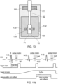
- the ECG based trigger module 67 provides a system trigger signal for actuating the motor of the pullback system 63 and the data capture based on an ECG signal from the patient whose artery is being scanned.
- the positive slope of the QRS wave 140 can be used as an initial trigger for the system trigger signal 141, although other features (or combinations of features) of the ECG signal could be used.
- the features of the ECG signal to be used in any particular context could be adjustable or selectable by the user, e.g. to take into account particular distortions or measuring conditions for a specific patient.
- the initial system trigger signal 141 may be used to trigger the spin up of the optical element motor 81, and a subsequent trigger signal 142 may be used to initiate the pullback system operation and to effectuate the data acquisition.
- the system trigger signals 141, 142 may be generated by detection of the QRS wave 140 as a readily detectable ECG feature
- the system trigger signal 142 for imaging is preferably delayed until the end of the T-wave 144 following the QRS wave 143. This is to avoid the period of strong cardiac motion.
- the time period 145 between the T-wave 144 and the next R-wave 146 is used for imaging and pullback, which is typically 60-70% of the entire cardiac cycle.
- the time period 145a for imaging could be extended to the beginning of the next T-wave 147.
- the catheter micro-motor 81 needs a short period to accelerate to the target speed, which can be triggered by the first system trigger signal 141. After this trigger signal, one or several cardiac cycles can be used for the acceleration of the motor, thus the system trigger signal 142 used for initiating pullback and data acquisition need not be the immediately succeeding signal to initial trigger signal 141. After the motor 81 reaches the target speed, the data acquisition and pullback are triggered at the same time by the appropriate system trigger signal 142.
- the trigger module 67 is operative to at least initiate an imaging scan based on cardiac event timing. That timing preferably involves the detection of a feature within the QRS complex and the assumption of a delay sufficient to pass the ensuing T-wave. However, any particular feature in the ECG data could be used if it provides sufficient temporal accuracy to initiate optical measurements within a period which is relatively undisrupted by cardiac motion.
- the trigger module may generally be operative not only to initiate an imaging scan, but also to stop the scan in time for a subsequent cardiac motion event.
- a method of use of the intravascular optical imaging system 60 (wherein this method of use is not part of the invention), which may be used in conjunction with the catheter-based optical imaging system defined by the claims, is as follows.
- the imaging probe 70 comprising outer and inner catheters 61 , 62 are inserted into the patient's artery, the inner catheter 61 being positioned at the start of the location of interest.
- the ECG trigger module 67 is coupled to the patient to obtain ECG data.
- the ECG-based trigger signal 141 may be used to switch on or speed up of the synchronous motor to the required rotational velocity. After sufficient (one or more) cardiac cycles to allow the required rotational velocity to be achieved and stabilised by the motor 81, an ECG-based trigger signal 142 is used to trigger the pullback system 63 and the data acquisition. With a pullback speed ⁇ 100 mm per second, the imaging of the relevant section of artery will be finished before the arrival of a subsequent R-wave 146.
- the image can be constructed based on the inverse Fourier transform of the data. With higher laser wavelength sweep rate and catheters with higher circumferential scan speed, it is possible to decrease further the sampling interval along the artery and improve image quality.
- a catheter speed of 3200 rps used in combination with a 1.6 MHz sweep-rate laser has been demonstrated.
- the sample interval along the artery i.e. the frame spacing
- the sample interval along the artery is decreased to 31 ⁇ m at a pullback speed of 100 mm per second.
- the image quality along longitudinal direction is improved as shown in figure 15.
- Figure 15a shows an image derived from a dataset generated with an optical element rotating at 400 rps and a pullback rate of 100 mm/sec.
- figure 15b shows an image derived from a dataset generated with an optical element rotating at 3200 rps and laser frequency 1.6 MHz and a pullback rate of 100 mm/sec.
- each 2D image ( figures 16a and 16b ) consists of 4000 lines.
- Figure 16a shows a frame rate of 400 Hz (1000 lines averaged from 4000 lines) and figure 16b shows a frame rate of 3.2 kHz (500 lines). Averaging the lines in groups of four, resulting in 1000 image lines, gains a higher sensitivity.
- the optical imaging system described herein is ideally suited for intracoronary imaging and can acquire a pullback data set of a relevant section of artery in a time less than one cardiac cycle.
- This approach to catheter-based coronary imaging eliminates the effects of cardiac motion on the dataset.
- Fast data acquisition can be achieved without sacrificing longitudinal sampling by a high-speed pullback system operating at >100 mm/s, a catheter or optical device rotation of >400 revolutions per second and a frequency-scanning laser system operating at >200,000 scans per second.
- a further advantage is a reduction of the flush volume required to create a blood-free field of view.
- Increasing the optical device rotation speed to >3200 rps allows the acquisition of an isotropically sampled dataset without motion artefacts.
- each scan can be triggered to a cardiac event.
- the imaging system described may generally be suitable for scanning any vessel walls in a context where pulsatile flow in the vessel or muscular activity near the vessel being imaged can cause disruption or disturbance to the measurement process and hence errors in datasets gathered therefrom, and where the timing of measurements can be suitably controlled by reference to cardiac events such as ECG waveforms to reduce the impact of the disruption or disturbance on the dataset. For example, the influence of the cardiac cycle can be seen in oesophageal scans.
- the trigger module 67 may generally be operative to only initiate an imaging scan if the duration of the scan is such that it can be completed within the expected time available. However, the trigger module 67 could also be configured to stop the scan in time for a subsequent cardiac motion event, and possibly even resume a scan during a next cardiac cycle. It would also be possible for the ECG-based trigger system 67 to more generally assess the duration of time period 145 available for scanning by monitoring a succession of cardiac cycles in the ECG data and then controlling one or more of the laser frequency scan rate; the frame rate (rotational speed) and the pullback speed to optimise use of an available measurement time period 145. Such optimisation could be used to achieve the best possible image quality for an available time period.
- the catheter-based imaging device can be mounted within or onto an inner catheter 62 which slides within and relative to an outer catheter 61.
- the inner catheter can be any structure configured to support the optical element 83, motor 81, fibre 85 and wires 84.
- the outer catheter can be any suitable structure for constraining the inner catheter within a vessel being imaged and suitable for the passage of optical radiation therethrough in a radial direction.
- cardiac event timing can be provided from various sensed or measured physiological signals from the patent. These physiological signals can include any one or more of ECG data; blood pressure measurement data (e.g. intracoronary or intracardiac pressure); blood oxygen measurement data; phonocardiogram data; and visual echocardiogram data. These can be acquired in real time using any one or more of one or more of: an ECG sensor; a blood pressure sensor, an SpO2 sensor; a phonocardiogram sensor; and a visual echocardiogram sensor.
- the ECG trigger module 67 can be replaced by, or supplemented with, any trigger module capable of initiating an imaging scan based on cardiac event timing data from any measureable physiological signals from the patient capable of providing cardiac event timing data.
Landscapes
- Health & Medical Sciences (AREA)
- Life Sciences & Earth Sciences (AREA)
- Engineering & Computer Science (AREA)
- Surgery (AREA)
- Animal Behavior & Ethology (AREA)
- Veterinary Medicine (AREA)
- Public Health (AREA)
- Biomedical Technology (AREA)
- Heart & Thoracic Surgery (AREA)
- Medical Informatics (AREA)
- Molecular Biology (AREA)
- General Health & Medical Sciences (AREA)
- Physics & Mathematics (AREA)
- Biophysics (AREA)
- Pathology (AREA)
- Cardiology (AREA)
- Physiology (AREA)
- Nuclear Medicine, Radiotherapy & Molecular Imaging (AREA)
- Radiology & Medical Imaging (AREA)
- Computer Vision & Pattern Recognition (AREA)
- Artificial Intelligence (AREA)
- Psychiatry (AREA)
- Signal Processing (AREA)
- Vascular Medicine (AREA)
- Pulmonology (AREA)
- Optics & Photonics (AREA)
- Endoscopes (AREA)
Applications Claiming Priority (2)
| Application Number | Priority Date | Filing Date | Title |
|---|---|---|---|
| GB1305031.5A GB2512077B (en) | 2013-03-19 | 2013-03-19 | Intravascular optical imaging system |
| PCT/EP2014/055342 WO2014147039A1 (en) | 2013-03-19 | 2014-03-17 | Intravascular optical imaging system |
Publications (2)
| Publication Number | Publication Date |
|---|---|
| EP2975999A1 EP2975999A1 (en) | 2016-01-27 |
| EP2975999B1 true EP2975999B1 (en) | 2024-10-09 |
Family
ID=48226680
Family Applications (1)
| Application Number | Title | Priority Date | Filing Date |
|---|---|---|---|
| EP14710881.5A Active EP2975999B1 (en) | 2013-03-19 | 2014-03-17 | Intravascular optical imaging system |
Country Status (5)
| Country | Link |
|---|---|
| US (1) | US9962127B2 (enExample) |
| EP (1) | EP2975999B1 (enExample) |
| JP (2) | JP6454681B2 (enExample) |
| GB (1) | GB2512077B (enExample) |
| WO (1) | WO2014147039A1 (enExample) |
Families Citing this family (71)
| Publication number | Priority date | Publication date | Assignee | Title |
|---|---|---|---|---|
| GB0522968D0 (en) | 2005-11-11 | 2005-12-21 | Popovich Milan M | Holographic illumination device |
| GB0718706D0 (en) | 2007-09-25 | 2007-11-07 | Creative Physics Ltd | Method and apparatus for reducing laser speckle |
| US11726332B2 (en) | 2009-04-27 | 2023-08-15 | Digilens Inc. | Diffractive projection apparatus |
| US9335604B2 (en) | 2013-12-11 | 2016-05-10 | Milan Momcilo Popovich | Holographic waveguide display |
| US11204540B2 (en) | 2009-10-09 | 2021-12-21 | Digilens Inc. | Diffractive waveguide providing a retinal image |
| US9274349B2 (en) | 2011-04-07 | 2016-03-01 | Digilens Inc. | Laser despeckler based on angular diversity |
| WO2016020630A2 (en) | 2014-08-08 | 2016-02-11 | Milan Momcilo Popovich | Waveguide laser illuminator incorporating a despeckler |
| EP2748670B1 (en) | 2011-08-24 | 2015-11-18 | Rockwell Collins, Inc. | Wearable data display |
| US10670876B2 (en) | 2011-08-24 | 2020-06-02 | Digilens Inc. | Waveguide laser illuminator incorporating a despeckler |
| US20150010265A1 (en) | 2012-01-06 | 2015-01-08 | Milan, Momcilo POPOVICH | Contact image sensor using switchable bragg gratings |
| EP2842003B1 (en) | 2012-04-25 | 2019-02-27 | Rockwell Collins, Inc. | Holographic wide angle display |
| US9456744B2 (en) | 2012-05-11 | 2016-10-04 | Digilens, Inc. | Apparatus for eye tracking |
| US9933684B2 (en) | 2012-11-16 | 2018-04-03 | Rockwell Collins, Inc. | Transparent waveguide display providing upper and lower fields of view having a specific light output aperture configuration |
| US10209517B2 (en) | 2013-05-20 | 2019-02-19 | Digilens, Inc. | Holographic waveguide eye tracker |
| US9727772B2 (en) | 2013-07-31 | 2017-08-08 | Digilens, Inc. | Method and apparatus for contact image sensing |
| US9754082B2 (en) | 2014-05-30 | 2017-09-05 | Heartflow, Inc. | Systems and methods for reporting blood flow characteristics |
| WO2016020632A1 (en) | 2014-08-08 | 2016-02-11 | Milan Momcilo Popovich | Method for holographic mastering and replication |
| WO2016042283A1 (en) | 2014-09-19 | 2016-03-24 | Milan Momcilo Popovich | Method and apparatus for generating input images for holographic waveguide displays |
| EP3198192A1 (en) | 2014-09-26 | 2017-08-02 | Milan Momcilo Popovich | Holographic waveguide opticaltracker |
| US10437064B2 (en) | 2015-01-12 | 2019-10-08 | Digilens Inc. | Environmentally isolated waveguide display |
| EP3245551B1 (en) | 2015-01-12 | 2019-09-18 | DigiLens Inc. | Waveguide light field displays |
| CN107533137A (zh) | 2015-01-20 | 2018-01-02 | 迪吉伦斯公司 | 全息波导激光雷达 |
| US9632226B2 (en) | 2015-02-12 | 2017-04-25 | Digilens Inc. | Waveguide grating device |
| WO2016146963A1 (en) | 2015-03-16 | 2016-09-22 | Popovich, Milan, Momcilo | Waveguide device incorporating a light pipe |
| US10591756B2 (en) | 2015-03-31 | 2020-03-17 | Digilens Inc. | Method and apparatus for contact image sensing |
| EP3282921B1 (en) | 2015-04-16 | 2022-02-16 | Gentuity LLC | Micro-optic probes for neurology |
| US10646198B2 (en) * | 2015-05-17 | 2020-05-12 | Lightlab Imaging, Inc. | Intravascular imaging and guide catheter detection methods and systems |
| JP6981967B2 (ja) | 2015-08-31 | 2021-12-17 | ジェンテュイティ・リミテッド・ライアビリティ・カンパニーGentuity, LLC | 撮像プローブおよびデリバリデバイスを含む撮像システム |
| CN105078425B (zh) * | 2015-09-09 | 2016-06-08 | 苏州润心医疗科技有限公司 | 冠状动脉负荷检测系统及检测方法 |
| WO2017060665A1 (en) | 2015-10-05 | 2017-04-13 | Milan Momcilo Popovich | Waveguide display |
| EP3398007B1 (en) | 2016-02-04 | 2024-09-11 | DigiLens, Inc. | Waveguide optical tracker |
| JP6895451B2 (ja) | 2016-03-24 | 2021-06-30 | ディジレンズ インコーポレイテッド | 偏光選択ホログラフィー導波管デバイスを提供するための方法および装置 |
| EP3433658B1 (en) | 2016-04-11 | 2023-08-09 | DigiLens, Inc. | Holographic waveguide apparatus for structured light projection |
| KR101851058B1 (ko) * | 2016-04-28 | 2018-04-20 | 한국과학기술원 | 수축기를 피하여 oct 이미징을 수행하는 방법 및 이를 수행하는 장치들 |
| EP3548939A4 (en) | 2016-12-02 | 2020-11-25 | DigiLens Inc. | UNIFORM OUTPUT LIGHTING WAVEGUIDE DEVICE |
| US10545346B2 (en) | 2017-01-05 | 2020-01-28 | Digilens Inc. | Wearable heads up displays |
| US11259702B2 (en) | 2017-08-29 | 2022-03-01 | Canon U.S.A., Inc. | Fiber optic imaging probe having cladding mode pullback trigger, and control method therefor |
| CN111386495B (zh) | 2017-10-16 | 2022-12-09 | 迪吉伦斯公司 | 用于倍增像素化显示器的图像分辨率的系统和方法 |
| CN107752985B (zh) * | 2017-11-17 | 2024-08-06 | 苏州阿格斯医疗技术有限公司 | Oct成像方法、oct成像导管及oct系统 |
| WO2019108598A1 (en) | 2017-11-28 | 2019-06-06 | Gentuity, Llc | Imaging system |
| US12453477B2 (en) * | 2017-12-13 | 2025-10-28 | President And Fellows Of Harvard College | Endoscopic imaging using nanoscale metasurfaces |
| JP7456929B2 (ja) | 2018-01-08 | 2024-03-27 | ディジレンズ インコーポレイテッド | 導波管セルを製造するためのシステムおよび方法 |
| CN114721242B (zh) | 2018-01-08 | 2025-08-15 | 迪吉伦斯公司 | 用于制造光学波导的方法 |
| WO2019136476A1 (en) | 2018-01-08 | 2019-07-11 | Digilens, Inc. | Waveguide architectures and related methods of manufacturing |
| JP7404243B2 (ja) | 2018-01-08 | 2023-12-25 | ディジレンズ インコーポレイテッド | 導波管セル内のホログラフィック格子の高スループット記録のためのシステムおよび方法 |
| US10690851B2 (en) | 2018-03-16 | 2020-06-23 | Digilens Inc. | Holographic waveguides incorporating birefringence control and methods for their fabrication |
| US11395597B2 (en) * | 2018-06-26 | 2022-07-26 | General Electric Company | System and method for evaluating blood flow in a vessel |
| US11402801B2 (en) | 2018-07-25 | 2022-08-02 | Digilens Inc. | Systems and methods for fabricating a multilayer optical structure |
| US12262872B2 (en) | 2018-09-17 | 2025-04-01 | Gentuity, Llc | Imaging system with optical pathway |
| US10791923B2 (en) | 2018-09-24 | 2020-10-06 | Canon U.S.A., Inc. | Ball lens for optical probe and methods therefor |
| US10794732B2 (en) | 2018-11-08 | 2020-10-06 | Canon U.S.A., Inc. | Apparatus, system and method for correcting nonuniform rotational distortion in an image comprising at least two stationary light transmitted fibers with predetermined position relative to an axis of rotation of at least one rotating fiber |
| WO2020149956A1 (en) | 2019-01-14 | 2020-07-23 | Digilens Inc. | Holographic waveguide display with light control layer |
| GB2580966A (en) * | 2019-02-01 | 2020-08-05 | Univ Erasmus Med Ct Rotterdam | Optical coherence elastography imaging |
| US20200247017A1 (en) | 2019-02-05 | 2020-08-06 | Digilens Inc. | Methods for Compensating for Optical Surface Nonuniformity |
| US20220283377A1 (en) | 2019-02-15 | 2022-09-08 | Digilens Inc. | Wide Angle Waveguide Display |
| CN113424034B (zh) * | 2019-02-15 | 2023-06-16 | 株式会社村田制作所 | 触觉以及接近传感器 |
| EP3924759B1 (en) | 2019-02-15 | 2025-07-30 | Digilens Inc. | Methods and apparatuses for providing a holographic waveguide display using integrated gratings |
| JP2022525165A (ja) | 2019-03-12 | 2022-05-11 | ディジレンズ インコーポレイテッド | ホログラフィック導波管バックライトおよび関連する製造方法 |
| EP3962346A4 (en) | 2019-04-30 | 2023-04-19 | Gentuity LLC | IMAGING PROBE WITH FLUID PRESSURIZATION ELEMENT |
| WO2020237024A1 (en) | 2019-05-21 | 2020-11-26 | Gentuity, Llc | Systems and methods for oct-guided treatment of a patient |
| EP3980825A4 (en) | 2019-06-07 | 2023-05-03 | Digilens Inc. | WAVEGUIDES WITH TRANSMITTING AND REFLECTING GRIDS AND RELATED MANUFACTURING PROCESSES |
| JP2022543571A (ja) | 2019-07-29 | 2022-10-13 | ディジレンズ インコーポレイテッド | 画素化されたディスプレイの画像解像度および視野を乗算するための方法および装置 |
| JP2022546413A (ja) | 2019-08-29 | 2022-11-04 | ディジレンズ インコーポレイテッド | 真空回折格子および製造方法 |
| EP4142567A4 (en) * | 2020-04-29 | 2024-06-26 | Gentuity, LLC | IMAGING SYSTEM |
| US11972561B2 (en) * | 2020-08-06 | 2024-04-30 | Canon U.S.A., Inc. | Auto-pullback triggering method for intracoronary imaging apparatuses or systems using blood clearing |
| EP4252048A4 (en) | 2020-12-21 | 2024-10-16 | Digilens Inc. | EYE LUMINESCENCE SUPPRESSION IN WAVEGUIDE-BASED DISPLAYS |
| WO2022150841A1 (en) | 2021-01-07 | 2022-07-14 | Digilens Inc. | Grating structures for color waveguides |
| KR20230153459A (ko) | 2021-03-05 | 2023-11-06 | 디지렌즈 인코포레이티드. | 진공 주기적 구조체 및 제조 방법 |
| IT202200010949A1 (it) | 2022-05-25 | 2023-11-25 | B Financial S R L | Unita’ ausiliaria di supporto, sosta e/o transito in imbarcazioni |
| WO2025076164A1 (en) * | 2023-10-03 | 2025-04-10 | Spryte Medical, Inc. | Imaging system |
| WO2025259837A1 (en) * | 2024-06-14 | 2025-12-18 | University Of Washington | Guided multimodal polarization-sensitive optical coherence tomography |
Citations (3)
| Publication number | Priority date | Publication date | Assignee | Title |
|---|---|---|---|---|
| US6501551B1 (en) * | 1991-04-29 | 2002-12-31 | Massachusetts Institute Of Technology | Fiber optic imaging endoscope interferometer with at least one faraday rotator |
| US20080177183A1 (en) * | 2007-01-19 | 2008-07-24 | Brian Courtney | Imaging probe with combined ultrasounds and optical means of imaging |
| WO2009137704A1 (en) * | 2008-05-07 | 2009-11-12 | Volcano Corporation | Optical imaging catheter for aberration balancing |
Family Cites Families (33)
| Publication number | Priority date | Publication date | Assignee | Title |
|---|---|---|---|---|
| JPS57185401A (en) * | 1981-05-12 | 1982-11-15 | Ricoh Co Ltd | Image forming element |
| US5240003A (en) | 1989-10-16 | 1993-08-31 | Du-Med B.V. | Ultrasonic instrument with a micro motor having stator coils on a flexible circuit board |
| US5321501A (en) * | 1991-04-29 | 1994-06-14 | Massachusetts Institute Of Technology | Method and apparatus for optical imaging with means for controlling the longitudinal range of the sample |
| US6134003A (en) * | 1991-04-29 | 2000-10-17 | Massachusetts Institute Of Technology | Method and apparatus for performing optical measurements using a fiber optic imaging guidewire, catheter or endoscope |
| JPH0829161A (ja) * | 1994-07-15 | 1996-02-02 | Keyence Corp | 光方向変換装置およびそれを用いた光電スイッチ |
| US5740808A (en) * | 1996-10-28 | 1998-04-21 | Ep Technologies, Inc | Systems and methods for guilding diagnostic or therapeutic devices in interior tissue regions |
| JP4021975B2 (ja) * | 1997-08-28 | 2007-12-12 | オリンパス株式会社 | 光走査プローブ装置 |
| US7343195B2 (en) * | 1999-05-18 | 2008-03-11 | Mediguide Ltd. | Method and apparatus for real time quantitative three-dimensional image reconstruction of a moving organ and intra-body navigation |
| JP2006524553A (ja) * | 2003-04-28 | 2006-11-02 | ボード オブ リージェンツ, ザ ユニバーシティ オブ テキサス システム | カテーテル画像化プローブ及び方法 |
| JP2005278762A (ja) * | 2004-03-29 | 2005-10-13 | Fujinon Corp | 穿刺型内視鏡用プローブ |
| JP5324095B2 (ja) * | 2004-08-24 | 2013-10-23 | ザ ジェネラル ホスピタル コーポレイション | 血管セグメントを画像化する方法および装置 |
| US8007440B2 (en) * | 2005-02-08 | 2011-08-30 | Volcano Corporation | Apparatus and methods for low-cost intravascular ultrasound imaging and for crossing severe vascular occlusions |
| US8538508B2 (en) * | 2005-12-09 | 2013-09-17 | Siemens Aktiengesellschaft | Method and apparatus for ECG-synchronized optically-based image acquisition and transformation |
| US20080146942A1 (en) * | 2006-12-13 | 2008-06-19 | Ep Medsystems, Inc. | Catheter Position Tracking Methods Using Fluoroscopy and Rotational Sensors |
| WO2008081653A1 (ja) * | 2006-12-28 | 2008-07-10 | Terumo Kabushiki Kaisha | 光プローブ |
| JP2008284340A (ja) * | 2007-01-31 | 2008-11-27 | Namiki Precision Jewel Co Ltd | モータ及びそのモータを備えたoct内視鏡プローブ |
| CH698693B1 (de) | 2007-01-31 | 2011-07-29 | Namiki Precision Jewel Co Ltd | Motor. |
| JP2008200283A (ja) * | 2007-02-20 | 2008-09-04 | Fujifilm Corp | 光プローブおよび光断層画像取得装置 |
| US20090147373A1 (en) * | 2007-10-19 | 2009-06-11 | University Of Central Florida Research Foundation, Inc. | Dynamic Focus Optical Probes |
| US8582934B2 (en) * | 2007-11-12 | 2013-11-12 | Lightlab Imaging, Inc. | Miniature optical elements for fiber-optic beam shaping |
| US20120022360A1 (en) * | 2008-03-28 | 2012-01-26 | Volcano Corporation | Methods for intravascular imaging and flushing |
| JP2010227159A (ja) * | 2009-03-26 | 2010-10-14 | Fujifilm Corp | 光ファイバープローブ装置 |
| US8285368B2 (en) | 2009-07-10 | 2012-10-09 | The Regents Of The University Of California | Endoscopic long range fourier domain optical coherence tomography (LR-FD-OCT) |
| ES2660147T3 (es) * | 2009-09-23 | 2018-03-21 | Lightlab Imaging, Inc. | Sistemas de depuración de sangre in vivo en una luz |
| JP5267999B2 (ja) * | 2009-10-26 | 2013-08-21 | 国立大学法人金沢大学 | 血管内視鏡システム |
| JP2012010776A (ja) * | 2010-06-29 | 2012-01-19 | Fujifilm Corp | 断層画像処理装置及び方法、並びに光干渉断層画像診断装置 |
| JP2013541392A (ja) * | 2010-11-08 | 2013-11-14 | コリブリ テクノロジーズ インコーポレーテッド | 低侵襲処置の間の改善された視覚化のためのシステム及び方法 |
| CA2824955C (en) * | 2011-01-31 | 2020-09-01 | Sunnybrook Health Sciences Centre | Ultrasonic probe with ultrasonic transducers addressable on common electrical channel |
| US9788731B2 (en) * | 2011-02-21 | 2017-10-17 | Jaywant Philip Parmar | Optical endoluminal far-field microscopic imaging catheter |
| JP5755956B2 (ja) * | 2011-06-30 | 2015-07-29 | テルモ株式会社 | 光干渉断層像形成装置 |
| JP5422849B2 (ja) * | 2011-07-26 | 2014-02-19 | 並木精密宝石株式会社 | 光イメージング用プローブ |
| US20130331689A1 (en) * | 2012-06-07 | 2013-12-12 | Poincare Systems, Inc. | Rotating shaft containing optical waveguide |
| WO2015102081A1 (ja) * | 2014-01-06 | 2015-07-09 | 並木精密宝石株式会社 | 光イメージング用プローブ |
-
2013
- 2013-03-19 GB GB1305031.5A patent/GB2512077B/en active Active
-
2014
- 2014-03-17 EP EP14710881.5A patent/EP2975999B1/en active Active
- 2014-03-17 JP JP2016503630A patent/JP6454681B2/ja active Active
- 2014-03-17 WO PCT/EP2014/055342 patent/WO2014147039A1/en not_active Ceased
- 2014-03-17 US US14/778,380 patent/US9962127B2/en active Active
-
2018
- 2018-12-17 JP JP2018235489A patent/JP6804508B2/ja active Active
Patent Citations (3)
| Publication number | Priority date | Publication date | Assignee | Title |
|---|---|---|---|---|
| US6501551B1 (en) * | 1991-04-29 | 2002-12-31 | Massachusetts Institute Of Technology | Fiber optic imaging endoscope interferometer with at least one faraday rotator |
| US20080177183A1 (en) * | 2007-01-19 | 2008-07-24 | Brian Courtney | Imaging probe with combined ultrasounds and optical means of imaging |
| WO2009137704A1 (en) * | 2008-05-07 | 2009-11-12 | Volcano Corporation | Optical imaging catheter for aberration balancing |
Non-Patent Citations (1)
| Title |
|---|
| F. PRATI ET AL: "Intracoronary optical coherence tomography, basic theory and image acquisition techniques", INTERNATIONAL JOURNAL OF CARDIOVASCULAR IMAGING, vol. 27, no. 2, 1 February 2011 (2011-02-01), NL, pages 251 - 258, XP055725697, ISSN: 1569-5794, DOI: 10.1007/s10554-011-9798-1 * |
Also Published As
| Publication number | Publication date |
|---|---|
| JP2016512772A (ja) | 2016-05-09 |
| WO2014147039A1 (en) | 2014-09-25 |
| GB201305031D0 (en) | 2013-05-01 |
| EP2975999A1 (en) | 2016-01-27 |
| GB2512077A (en) | 2014-09-24 |
| JP6804508B2 (ja) | 2020-12-23 |
| JP2019058741A (ja) | 2019-04-18 |
| US20160228071A1 (en) | 2016-08-11 |
| JP6454681B2 (ja) | 2019-01-16 |
| GB2512077B (en) | 2019-10-23 |
| US9962127B2 (en) | 2018-05-08 |
Similar Documents
| Publication | Publication Date | Title |
|---|---|---|
| EP2975999B1 (en) | Intravascular optical imaging system | |
| JP7069236B2 (ja) | イメージングシステムの動作を制御する方法及びイメージを取得するシステム | |
| CA2644319C (en) | Artery imaging system | |
| JP7383668B2 (ja) | 画像同期の方法及びシステム | |
| US20050020925A1 (en) | Optical coherence tomography system for the examination of human or animal tissue or of organs | |
| EP3932287B1 (en) | Microlens array optical coherence tomography (mla-oct) imaging system | |
| KR101731728B1 (ko) | 관상동맥 혈관 고속 스캐닝 장치 및 방법 | |
| CN113180631A (zh) | 基于血管内成像的血流速度、血流储备分数的分析方法 | |
| JP6284944B2 (ja) | 画像診断装置及びその作動方法及び記憶媒体 | |
| JP2004121840A (ja) | 周期的に運動する器官のct画像形成方法およびこの方法を実施するためのct装置 | |
| US11944778B2 (en) | Methods and systems for automatic pullback trigger | |
| JP6100911B2 (ja) | 画像診断装置及びその作動方法 | |
| GB2573463A (en) | Intravascular optical imaging system | |
| JP5400430B2 (ja) | 生体断層画像生成装置及びその作動方法 |
Legal Events
| Date | Code | Title | Description |
|---|---|---|---|
| PUAI | Public reference made under article 153(3) epc to a published international application that has entered the european phase |
Free format text: ORIGINAL CODE: 0009012 |
|
| 17P | Request for examination filed |
Effective date: 20150917 |
|
| AK | Designated contracting states |
Kind code of ref document: A1 Designated state(s): AL AT BE BG CH CY CZ DE DK EE ES FI FR GB GR HR HU IE IS IT LI LT LU LV MC MK MT NL NO PL PT RO RS SE SI SK SM TR |
|
| AX | Request for extension of the european patent |
Extension state: BA ME |
|
| RAP1 | Party data changed (applicant data changed or rights of an application transferred) |
Owner name: ERASMUS UNIVERSITY MEDICAL CENTER ROTTERDAM |
|
| DAX | Request for extension of the european patent (deleted) | ||
| PUAG | Search results despatched under rule 164(2) epc together with communication from examining division |
Free format text: ORIGINAL CODE: 0009017 |
|
| STAA | Information on the status of an ep patent application or granted ep patent |
Free format text: STATUS: EXAMINATION IS IN PROGRESS |
|
| 17Q | First examination report despatched |
Effective date: 20200903 |
|
| B565 | Issuance of search results under rule 164(2) epc |
Effective date: 20200903 |
|
| RIC1 | Information provided on ipc code assigned before grant |
Ipc: A61B 5/0452 20060101ALI20200831BHEP Ipc: A61B 5/00 20060101AFI20200831BHEP Ipc: A61B 5/02 20060101ALI20200831BHEP |
|
| P01 | Opt-out of the competence of the unified patent court (upc) registered |
Effective date: 20230516 |
|
| GRAP | Despatch of communication of intention to grant a patent |
Free format text: ORIGINAL CODE: EPIDOSNIGR1 |
|
| STAA | Information on the status of an ep patent application or granted ep patent |
Free format text: STATUS: GRANT OF PATENT IS INTENDED |
|
| RIC1 | Information provided on ipc code assigned before grant |
Ipc: A61B 5/349 20210101ALI20231109BHEP Ipc: A61B 5/02 20060101ALI20231109BHEP Ipc: A61B 5/00 20060101AFI20231109BHEP |
|
| INTG | Intention to grant announced |
Effective date: 20231130 |
|
| RIN1 | Information on inventor provided before grant (corrected) |
Inventor name: VAN SOEST, GIJS Inventor name: VAN DER STEEN, ANTONIUS FRANCISCUS WILHELMUS Inventor name: LANCEE, CHARLES THEODOOR Inventor name: WANG, TIANSHI |
|
| GRAJ | Information related to disapproval of communication of intention to grant by the applicant or resumption of examination proceedings by the epo deleted |
Free format text: ORIGINAL CODE: EPIDOSDIGR1 |
|
| STAA | Information on the status of an ep patent application or granted ep patent |
Free format text: STATUS: EXAMINATION IS IN PROGRESS |
|
| GRAP | Despatch of communication of intention to grant a patent |
Free format text: ORIGINAL CODE: EPIDOSNIGR1 |
|
| STAA | Information on the status of an ep patent application or granted ep patent |
Free format text: STATUS: GRANT OF PATENT IS INTENDED |
|
| INTC | Intention to grant announced (deleted) | ||
| INTG | Intention to grant announced |
Effective date: 20240425 |
|
| GRAS | Grant fee paid |
Free format text: ORIGINAL CODE: EPIDOSNIGR3 |
|
| RAP1 | Party data changed (applicant data changed or rights of an application transferred) |
Owner name: SPECTRAWAVE, INC. |
|
| GRAA | (expected) grant |
Free format text: ORIGINAL CODE: 0009210 |
|
| STAA | Information on the status of an ep patent application or granted ep patent |
Free format text: STATUS: THE PATENT HAS BEEN GRANTED |
|
| AK | Designated contracting states |
Kind code of ref document: B1 Designated state(s): AL AT BE BG CH CY CZ DE DK EE ES FI FR GB GR HR HU IE IS IT LI LT LU LV MC MK MT NL NO PL PT RO RS SE SI SK SM TR |
|
| RAP3 | Party data changed (applicant data changed or rights of an application transferred) |
Owner name: SPECTRAWAVE, INC. |
|
| REG | Reference to a national code |
Ref country code: GB Ref legal event code: FG4D |
|
| REG | Reference to a national code |
Ref country code: CH Ref legal event code: EP |
|
| REG | Reference to a national code |
Ref country code: DE Ref legal event code: R096 Ref document number: 602014090977 Country of ref document: DE |
|
| REG | Reference to a national code |
Ref country code: IE Ref legal event code: FG4D |
|
| REG | Reference to a national code |
Ref country code: LT Ref legal event code: MG9D |
|
| REG | Reference to a national code |
Ref country code: NL Ref legal event code: MP Effective date: 20241009 |
|
| REG | Reference to a national code |
Ref country code: AT Ref legal event code: MK05 Ref document number: 1729638 Country of ref document: AT Kind code of ref document: T Effective date: 20241009 |
|
| PG25 | Lapsed in a contracting state [announced via postgrant information from national office to epo] |
Ref country code: NL Free format text: LAPSE BECAUSE OF FAILURE TO SUBMIT A TRANSLATION OF THE DESCRIPTION OR TO PAY THE FEE WITHIN THE PRESCRIBED TIME-LIMIT Effective date: 20241009 |
|
| PG25 | Lapsed in a contracting state [announced via postgrant information from national office to epo] |
Ref country code: NL Free format text: LAPSE BECAUSE OF FAILURE TO SUBMIT A TRANSLATION OF THE DESCRIPTION OR TO PAY THE FEE WITHIN THE PRESCRIBED TIME-LIMIT Effective date: 20241009 |
|
| PG25 | Lapsed in a contracting state [announced via postgrant information from national office to epo] |
Ref country code: IS Free format text: LAPSE BECAUSE OF FAILURE TO SUBMIT A TRANSLATION OF THE DESCRIPTION OR TO PAY THE FEE WITHIN THE PRESCRIBED TIME-LIMIT Effective date: 20250209 Ref country code: PT Free format text: LAPSE BECAUSE OF FAILURE TO SUBMIT A TRANSLATION OF THE DESCRIPTION OR TO PAY THE FEE WITHIN THE PRESCRIBED TIME-LIMIT Effective date: 20250210 Ref country code: HR Free format text: LAPSE BECAUSE OF FAILURE TO SUBMIT A TRANSLATION OF THE DESCRIPTION OR TO PAY THE FEE WITHIN THE PRESCRIBED TIME-LIMIT Effective date: 20241009 |
|
| PG25 | Lapsed in a contracting state [announced via postgrant information from national office to epo] |
Ref country code: FI Free format text: LAPSE BECAUSE OF FAILURE TO SUBMIT A TRANSLATION OF THE DESCRIPTION OR TO PAY THE FEE WITHIN THE PRESCRIBED TIME-LIMIT Effective date: 20241009 |
|
| PG25 | Lapsed in a contracting state [announced via postgrant information from national office to epo] |
Ref country code: BG Free format text: LAPSE BECAUSE OF FAILURE TO SUBMIT A TRANSLATION OF THE DESCRIPTION OR TO PAY THE FEE WITHIN THE PRESCRIBED TIME-LIMIT Effective date: 20241009 |
|
| PG25 | Lapsed in a contracting state [announced via postgrant information from national office to epo] |
Ref country code: ES Free format text: LAPSE BECAUSE OF FAILURE TO SUBMIT A TRANSLATION OF THE DESCRIPTION OR TO PAY THE FEE WITHIN THE PRESCRIBED TIME-LIMIT Effective date: 20241009 |
|
| PG25 | Lapsed in a contracting state [announced via postgrant information from national office to epo] |
Ref country code: NO Free format text: LAPSE BECAUSE OF FAILURE TO SUBMIT A TRANSLATION OF THE DESCRIPTION OR TO PAY THE FEE WITHIN THE PRESCRIBED TIME-LIMIT Effective date: 20250109 |
|
| PG25 | Lapsed in a contracting state [announced via postgrant information from national office to epo] |
Ref country code: LV Free format text: LAPSE BECAUSE OF FAILURE TO SUBMIT A TRANSLATION OF THE DESCRIPTION OR TO PAY THE FEE WITHIN THE PRESCRIBED TIME-LIMIT Effective date: 20241009 Ref country code: AT Free format text: LAPSE BECAUSE OF FAILURE TO SUBMIT A TRANSLATION OF THE DESCRIPTION OR TO PAY THE FEE WITHIN THE PRESCRIBED TIME-LIMIT Effective date: 20241009 Ref country code: GR Free format text: LAPSE BECAUSE OF FAILURE TO SUBMIT A TRANSLATION OF THE DESCRIPTION OR TO PAY THE FEE WITHIN THE PRESCRIBED TIME-LIMIT Effective date: 20250110 |
|
| PG25 | Lapsed in a contracting state [announced via postgrant information from national office to epo] |
Ref country code: PL Free format text: LAPSE BECAUSE OF FAILURE TO SUBMIT A TRANSLATION OF THE DESCRIPTION OR TO PAY THE FEE WITHIN THE PRESCRIBED TIME-LIMIT Effective date: 20241009 |
|
| PG25 | Lapsed in a contracting state [announced via postgrant information from national office to epo] |
Ref country code: RS Free format text: LAPSE BECAUSE OF FAILURE TO SUBMIT A TRANSLATION OF THE DESCRIPTION OR TO PAY THE FEE WITHIN THE PRESCRIBED TIME-LIMIT Effective date: 20250109 |
|
| PG25 | Lapsed in a contracting state [announced via postgrant information from national office to epo] |
Ref country code: SM Free format text: LAPSE BECAUSE OF FAILURE TO SUBMIT A TRANSLATION OF THE DESCRIPTION OR TO PAY THE FEE WITHIN THE PRESCRIBED TIME-LIMIT Effective date: 20241009 |
|
| PG25 | Lapsed in a contracting state [announced via postgrant information from national office to epo] |
Ref country code: DK Free format text: LAPSE BECAUSE OF FAILURE TO SUBMIT A TRANSLATION OF THE DESCRIPTION OR TO PAY THE FEE WITHIN THE PRESCRIBED TIME-LIMIT Effective date: 20241009 |
|
| REG | Reference to a national code |
Ref country code: DE Ref legal event code: R097 Ref document number: 602014090977 Country of ref document: DE |
|
| PG25 | Lapsed in a contracting state [announced via postgrant information from national office to epo] |
Ref country code: EE Free format text: LAPSE BECAUSE OF FAILURE TO SUBMIT A TRANSLATION OF THE DESCRIPTION OR TO PAY THE FEE WITHIN THE PRESCRIBED TIME-LIMIT Effective date: 20241009 |
|
| PG25 | Lapsed in a contracting state [announced via postgrant information from national office to epo] |
Ref country code: RO Free format text: LAPSE BECAUSE OF FAILURE TO SUBMIT A TRANSLATION OF THE DESCRIPTION OR TO PAY THE FEE WITHIN THE PRESCRIBED TIME-LIMIT Effective date: 20241009 |
|
| PG25 | Lapsed in a contracting state [announced via postgrant information from national office to epo] |
Ref country code: SK Free format text: LAPSE BECAUSE OF FAILURE TO SUBMIT A TRANSLATION OF THE DESCRIPTION OR TO PAY THE FEE WITHIN THE PRESCRIBED TIME-LIMIT Effective date: 20241009 |
|
| PG25 | Lapsed in a contracting state [announced via postgrant information from national office to epo] |
Ref country code: CZ Free format text: LAPSE BECAUSE OF FAILURE TO SUBMIT A TRANSLATION OF THE DESCRIPTION OR TO PAY THE FEE WITHIN THE PRESCRIBED TIME-LIMIT Effective date: 20241009 |
|
| PLBE | No opposition filed within time limit |
Free format text: ORIGINAL CODE: 0009261 |
|
| STAA | Information on the status of an ep patent application or granted ep patent |
Free format text: STATUS: NO OPPOSITION FILED WITHIN TIME LIMIT |
|
| PG25 | Lapsed in a contracting state [announced via postgrant information from national office to epo] |
Ref country code: SE Free format text: LAPSE BECAUSE OF FAILURE TO SUBMIT A TRANSLATION OF THE DESCRIPTION OR TO PAY THE FEE WITHIN THE PRESCRIBED TIME-LIMIT Effective date: 20241009 |
|
| 26N | No opposition filed |
Effective date: 20250710 |
|
| PG25 | Lapsed in a contracting state [announced via postgrant information from national office to epo] |
Ref country code: MC Free format text: LAPSE BECAUSE OF FAILURE TO SUBMIT A TRANSLATION OF THE DESCRIPTION OR TO PAY THE FEE WITHIN THE PRESCRIBED TIME-LIMIT Effective date: 20241009 |
|
| REG | Reference to a national code |
Ref country code: CH Ref legal event code: H13 Free format text: ST27 STATUS EVENT CODE: U-0-0-H10-H13 (AS PROVIDED BY THE NATIONAL OFFICE) Effective date: 20251023 |
|
| PG25 | Lapsed in a contracting state [announced via postgrant information from national office to epo] |
Ref country code: LU Free format text: LAPSE BECAUSE OF NON-PAYMENT OF DUE FEES Effective date: 20250317 |
|
| REG | Reference to a national code |
Ref country code: BE Ref legal event code: MM Effective date: 20250331 |
|
| PG25 | Lapsed in a contracting state [announced via postgrant information from national office to epo] |
Ref country code: BE Free format text: LAPSE BECAUSE OF NON-PAYMENT OF DUE FEES Effective date: 20250331 |
|
| PG25 | Lapsed in a contracting state [announced via postgrant information from national office to epo] |
Ref country code: CH Free format text: LAPSE BECAUSE OF NON-PAYMENT OF DUE FEES Effective date: 20250331 |
|
| PG25 | Lapsed in a contracting state [announced via postgrant information from national office to epo] |
Ref country code: IE Free format text: LAPSE BECAUSE OF NON-PAYMENT OF DUE FEES Effective date: 20250317 |
|
| PGFP | Annual fee paid to national office [announced via postgrant information from national office to epo] |
Ref country code: GB Payment date: 20260324 Year of fee payment: 13 |
|
| PGFP | Annual fee paid to national office [announced via postgrant information from national office to epo] |
Ref country code: DE Payment date: 20260319 Year of fee payment: 13 |
|
| REG | Reference to a national code |
Ref country code: DE Ref legal event code: R081 Ref document number: 602014090977 Country of ref document: DE Owner name: KONINKLIJKE PHILIPS N.V., NL Free format text: FORMER OWNER: SPECTRAWAVE, INC., BEDFORD, MA, US Ref country code: DE Ref legal event code: R082 Ref document number: 602014090977 Country of ref document: DE |
|
| PGFP | Annual fee paid to national office [announced via postgrant information from national office to epo] |
Ref country code: IT Payment date: 20260324 Year of fee payment: 13 |
|
| PGFP | Annual fee paid to national office [announced via postgrant information from national office to epo] |
Ref country code: FR Payment date: 20260320 Year of fee payment: 13 |