EP2975337B1 - Refrigerating system - Google Patents
Refrigerating system Download PDFInfo
- Publication number
- EP2975337B1 EP2975337B1 EP14791203.4A EP14791203A EP2975337B1 EP 2975337 B1 EP2975337 B1 EP 2975337B1 EP 14791203 A EP14791203 A EP 14791203A EP 2975337 B1 EP2975337 B1 EP 2975337B1
- Authority
- EP
- European Patent Office
- Prior art keywords
- compressor
- unit
- refrigerant
- circulation path
- refrigeration system
- Prior art date
- Legal status (The legal status is an assumption and is not a legal conclusion. Google has not performed a legal analysis and makes no representation as to the accuracy of the status listed.)
- Active
Links
- 238000005057 refrigeration Methods 0.000 claims description 77
- 239000003507 refrigerant Substances 0.000 claims description 70
- 238000001816 cooling Methods 0.000 claims description 44
- IJGRMHOSHXDMSA-UHFFFAOYSA-N Atomic nitrogen Chemical compound N#N IJGRMHOSHXDMSA-UHFFFAOYSA-N 0.000 claims description 20
- 239000007788 liquid Substances 0.000 claims description 10
- 229910052757 nitrogen Inorganic materials 0.000 claims description 10
- 230000005856 abnormality Effects 0.000 description 22
- 238000007906 compression Methods 0.000 description 12
- 238000010586 diagram Methods 0.000 description 12
- 230000006835 compression Effects 0.000 description 9
- 238000010276 construction Methods 0.000 description 9
- 238000000034 method Methods 0.000 description 8
- 239000000498 cooling water Substances 0.000 description 5
- 238000009434 installation Methods 0.000 description 4
- 239000007789 gas Substances 0.000 description 2
- 230000003247 decreasing effect Effects 0.000 description 1
- 230000000694 effects Effects 0.000 description 1
- 230000007257 malfunction Effects 0.000 description 1
- 239000000463 material Substances 0.000 description 1
- 229910052754 neon Inorganic materials 0.000 description 1
- GKAOGPIIYCISHV-UHFFFAOYSA-N neon atom Chemical compound [Ne] GKAOGPIIYCISHV-UHFFFAOYSA-N 0.000 description 1
- 239000002887 superconductor Substances 0.000 description 1
Images


Classifications
-
- F—MECHANICAL ENGINEERING; LIGHTING; HEATING; WEAPONS; BLASTING
- F25—REFRIGERATION OR COOLING; COMBINED HEATING AND REFRIGERATION SYSTEMS; HEAT PUMP SYSTEMS; MANUFACTURE OR STORAGE OF ICE; LIQUEFACTION SOLIDIFICATION OF GASES
- F25B—REFRIGERATION MACHINES, PLANTS OR SYSTEMS; COMBINED HEATING AND REFRIGERATION SYSTEMS; HEAT PUMP SYSTEMS
- F25B1/00—Compression machines, plants or systems with non-reversible cycle
- F25B1/10—Compression machines, plants or systems with non-reversible cycle with multi-stage compression
-
- F—MECHANICAL ENGINEERING; LIGHTING; HEATING; WEAPONS; BLASTING
- F25—REFRIGERATION OR COOLING; COMBINED HEATING AND REFRIGERATION SYSTEMS; HEAT PUMP SYSTEMS; MANUFACTURE OR STORAGE OF ICE; LIQUEFACTION SOLIDIFICATION OF GASES
- F25B—REFRIGERATION MACHINES, PLANTS OR SYSTEMS; COMBINED HEATING AND REFRIGERATION SYSTEMS; HEAT PUMP SYSTEMS
- F25B11/00—Compression machines, plants or systems, using turbines, e.g. gas turbines
- F25B11/02—Compression machines, plants or systems, using turbines, e.g. gas turbines as expanders
-
- F—MECHANICAL ENGINEERING; LIGHTING; HEATING; WEAPONS; BLASTING
- F25—REFRIGERATION OR COOLING; COMBINED HEATING AND REFRIGERATION SYSTEMS; HEAT PUMP SYSTEMS; MANUFACTURE OR STORAGE OF ICE; LIQUEFACTION SOLIDIFICATION OF GASES
- F25B—REFRIGERATION MACHINES, PLANTS OR SYSTEMS; COMBINED HEATING AND REFRIGERATION SYSTEMS; HEAT PUMP SYSTEMS
- F25B27/00—Machines, plants or systems, using particular sources of energy
-
- F—MECHANICAL ENGINEERING; LIGHTING; HEATING; WEAPONS; BLASTING
- F25—REFRIGERATION OR COOLING; COMBINED HEATING AND REFRIGERATION SYSTEMS; HEAT PUMP SYSTEMS; MANUFACTURE OR STORAGE OF ICE; LIQUEFACTION SOLIDIFICATION OF GASES
- F25B—REFRIGERATION MACHINES, PLANTS OR SYSTEMS; COMBINED HEATING AND REFRIGERATION SYSTEMS; HEAT PUMP SYSTEMS
- F25B41/00—Fluid-circulation arrangements
- F25B41/20—Disposition of valves, e.g. of on-off valves or flow control valves
- F25B41/24—Arrangement of shut-off valves for disconnecting a part of the refrigerant cycle, e.g. an outdoor part
-
- F—MECHANICAL ENGINEERING; LIGHTING; HEATING; WEAPONS; BLASTING
- F25—REFRIGERATION OR COOLING; COMBINED HEATING AND REFRIGERATION SYSTEMS; HEAT PUMP SYSTEMS; MANUFACTURE OR STORAGE OF ICE; LIQUEFACTION SOLIDIFICATION OF GASES
- F25B—REFRIGERATION MACHINES, PLANTS OR SYSTEMS; COMBINED HEATING AND REFRIGERATION SYSTEMS; HEAT PUMP SYSTEMS
- F25B6/00—Compression machines, plants or systems, with several condenser circuits
- F25B6/04—Compression machines, plants or systems, with several condenser circuits arranged in series
-
- F—MECHANICAL ENGINEERING; LIGHTING; HEATING; WEAPONS; BLASTING
- F25—REFRIGERATION OR COOLING; COMBINED HEATING AND REFRIGERATION SYSTEMS; HEAT PUMP SYSTEMS; MANUFACTURE OR STORAGE OF ICE; LIQUEFACTION SOLIDIFICATION OF GASES
- F25B—REFRIGERATION MACHINES, PLANTS OR SYSTEMS; COMBINED HEATING AND REFRIGERATION SYSTEMS; HEAT PUMP SYSTEMS
- F25B2339/00—Details of evaporators; Details of condensers
- F25B2339/04—Details of condensers
- F25B2339/047—Water-cooled condensers
-
- F—MECHANICAL ENGINEERING; LIGHTING; HEATING; WEAPONS; BLASTING
- F25—REFRIGERATION OR COOLING; COMBINED HEATING AND REFRIGERATION SYSTEMS; HEAT PUMP SYSTEMS; MANUFACTURE OR STORAGE OF ICE; LIQUEFACTION SOLIDIFICATION OF GASES
- F25B—REFRIGERATION MACHINES, PLANTS OR SYSTEMS; COMBINED HEATING AND REFRIGERATION SYSTEMS; HEAT PUMP SYSTEMS
- F25B2400/00—General features or devices for refrigeration machines, plants or systems, combined heating and refrigeration systems or heat-pump systems, i.e. not limited to a particular subgroup of F25B
- F25B2400/07—Details of compressors or related parts
- F25B2400/072—Intercoolers therefor
-
- F—MECHANICAL ENGINEERING; LIGHTING; HEATING; WEAPONS; BLASTING
- F25—REFRIGERATION OR COOLING; COMBINED HEATING AND REFRIGERATION SYSTEMS; HEAT PUMP SYSTEMS; MANUFACTURE OR STORAGE OF ICE; LIQUEFACTION SOLIDIFICATION OF GASES
- F25B—REFRIGERATION MACHINES, PLANTS OR SYSTEMS; COMBINED HEATING AND REFRIGERATION SYSTEMS; HEAT PUMP SYSTEMS
- F25B2400/00—General features or devices for refrigeration machines, plants or systems, combined heating and refrigeration systems or heat-pump systems, i.e. not limited to a particular subgroup of F25B
- F25B2400/07—Details of compressors or related parts
- F25B2400/075—Details of compressors or related parts with parallel compressors
-
- F—MECHANICAL ENGINEERING; LIGHTING; HEATING; WEAPONS; BLASTING
- F25—REFRIGERATION OR COOLING; COMBINED HEATING AND REFRIGERATION SYSTEMS; HEAT PUMP SYSTEMS; MANUFACTURE OR STORAGE OF ICE; LIQUEFACTION SOLIDIFICATION OF GASES
- F25B—REFRIGERATION MACHINES, PLANTS OR SYSTEMS; COMBINED HEATING AND REFRIGERATION SYSTEMS; HEAT PUMP SYSTEMS
- F25B2400/00—General features or devices for refrigeration machines, plants or systems, combined heating and refrigeration systems or heat-pump systems, i.e. not limited to a particular subgroup of F25B
- F25B2400/14—Power generation using energy from the expansion of the refrigerant
-
- F—MECHANICAL ENGINEERING; LIGHTING; HEATING; WEAPONS; BLASTING
- F25—REFRIGERATION OR COOLING; COMBINED HEATING AND REFRIGERATION SYSTEMS; HEAT PUMP SYSTEMS; MANUFACTURE OR STORAGE OF ICE; LIQUEFACTION SOLIDIFICATION OF GASES
- F25B—REFRIGERATION MACHINES, PLANTS OR SYSTEMS; COMBINED HEATING AND REFRIGERATION SYSTEMS; HEAT PUMP SYSTEMS
- F25B25/00—Machines, plants or systems, using a combination of modes of operation covered by two or more of the groups F25B1/00 - F25B23/00
- F25B25/005—Machines, plants or systems, using a combination of modes of operation covered by two or more of the groups F25B1/00 - F25B23/00 using primary and secondary systems
-
- F—MECHANICAL ENGINEERING; LIGHTING; HEATING; WEAPONS; BLASTING
- F25—REFRIGERATION OR COOLING; COMBINED HEATING AND REFRIGERATION SYSTEMS; HEAT PUMP SYSTEMS; MANUFACTURE OR STORAGE OF ICE; LIQUEFACTION SOLIDIFICATION OF GASES
- F25B—REFRIGERATION MACHINES, PLANTS OR SYSTEMS; COMBINED HEATING AND REFRIGERATION SYSTEMS; HEAT PUMP SYSTEMS
- F25B9/00—Compression machines, plants or systems, in which the refrigerant is air or other gas of low boiling point
- F25B9/06—Compression machines, plants or systems, in which the refrigerant is air or other gas of low boiling point using expanders
Definitions
- the present invention relates to a refrigeration system comprising a refrigeration cycle having: a circulation path in which a refrigerant flows; and a compressor for compressing the refrigerant, a heat exchanger for cooling the refrigerant compressed by the compressor, an expansion turbine for expanding the refrigerant cooled by the heat exchanger to generate cold heat, and a cooling part for cooling an object to be cooled by the cold heat, which are provided on the circulation path in order.
- a refrigeration system where a refrigerant is cooled by a refrigeration cycle using a compressor and an expansion turbine to cool an object is widely known.
- Examples of such kind of refrigeration system include a refrigeration system having a plurality of compressors or expansion turbines arranged in series on a circulation path in which the refrigerant flows to compress or expand the refrigerant in multiple stages thereby to improve the cooling capacity, as disclosed in Patent Document 1, 2 or 3.
- the document DE 2122064 A1 discloses a refrigeration system comprising a Brayton cycle having a circulation path in which a refrigerant flows and a compressor for compressing the refrigerant, a heat exchanger for cooling the refrigerant compressed by the compressor, an expansion turbine for expanding the refrigerant cooled by the heat exchanger to generate cold heat, and a cooling part for cooling.
- the present invention is to provide a refrigeration system capable of ensuring excellent reliability and being efficiently installed in a limited space.
- the cooling system comprises a refrigeration system comprising a refrigeration cycle having: a circulation path in which a refrigerant flows; and at least one compressor for compressing the refrigerant, a heat exchanger for cooling the refrigerant compressed by the compressor, at least one expansion turbine for expanding the refrigerant cooled by the heat exchanger to generate cold heat, and a cooling part for cooling an object to be cooled by the cold heat, which are provided on the circulation path in order, wherein at least either the at least one compressor or the at least one expansion turbine comprises a plurality of compressors or expansion turbines which are arranged in parallel with one another with respect to the circulation path.
- a plurality of compressors or expansion turbines which are rotating machines constituting the cooling cycle, are arranged in parallel with one another with respect to the circulation path in which the refrigerant flows, whereby even in case of an abnormality (e.g. failure) of one of the plurality of the rotating machines, another one of the plurality of the rotating machines can function as a backup, and it is thereby possible to continue the operation.
- rotating machines tend to have a high risk of abnormality as compared with other components of a refrigeration system.
- by preparing a backup only for a rotating machine having a high risk of abnormality it is possible to increase reliability while suppressing increase in size of the whole system.
- each of the plurality of compressors or each of the plurality of expansion turbines arranged in parallel with one another in the circulation path is configured to be disconnectable from the circulation path via a switching valve.
- the at least one expansion turbine is housed together with the cooling part in at least one cold box insulated from the outside, the at least one compressor is housed in at least one compressor unit other than the at least one cold box, and the at least one compressor unit is placed at a position farther from the object to be cooled than the at least one cold box.
- the expansion turbine to generate a cold heat, together with the cooling part, in the cold box insulated from the outside, it is possible to suppress heat loss and to improve cooling efficiency.
- the compressor is housed in the compressor unit other than the cold box because the temperature of the refrigerant becomes relatively high in the compressor.
- the compressor unit at a position farther from the object to be cooled than the cold box, it is possible to realize a refrigeration system which can be installed in a small space around the object to be cooled while ensuring refrigeration capacity.
- the at least one compressor unit may comprise a plurality of compressor units arranged in parallel with one another with respect to the at least one cold box via a switching valve.
- a compressor unit is selectable from among the plurality of compressor units via the switching valve.
- the at least one cold box may comprise a plurality of cold boxes
- the at least one compressor unit may comprise a plurality of compressor units, both of the plurality of cold boxes and the plurality of the compressor units being arranged in parallel with one another with respect to the object to be cooled.
- a plurality of cold boxes and a plurality of compressor units are provided with respect to the object to be cooled, whereby it is possible to build a system having higher reliability.
- the at least one compressor comprises a first compressor, a second compressor and a third compressor arranged in series on the circulation path, the first compressor is connected to an output shaft of a first electric motor together with the second compressor, and the third compressor is connected to an output shaft of a second electric motor together with one of the at least one expansion turbine.
- a plurality of compressors are arranged in series on the circulation path, whereby compressing in multiple stages can be carried out.
- the first compressor is connected to the output shaft of the first electric motor together with the second compressor, whereby it is possible to make the structure simpler than a case where power source is provided for each compressor.
- the third compressor is connected to the output shaft of the second electric motor together with the expansion turbine, whereby it is possible to make the structure simple. Further, by such a configuration, power generated by the expansion turbine contributes to the compressing power of the third compressor, which may provide effectiveness.
- a plurality of compressors or expansion turbines which are rotating machines constituting the cooling cycle, are arranged in parallel with one another with respect to the circulation path in which the refrigerant flows, whereby even in case of an abnormality (e.g. failure) of one of the plurality of the rotating machines, another one of the plurality of the rotating machines can function as a backup, and it is thereby possible to continue the operation.
- rotating machines tend to have a high risk of abnormality as compared with other components of a refrigeration system.
- by preparing a backup only for a rotating machine having a high risk of abnormality it is possible to increase reliability while suppressing increase in size of the whole system.
- Fig. 6 is a diagram illustrating a whole construction of a refrigeration system 100' of a related technique.
- Figs. 7a and 7b is a T-S diagram of a Brayton cycle applied to the refrigeration system 100', where the vertical axis represents the temperature T [K], and the horizontal axis represents the entropy [KJ/kgK].
- Fig. 7b is an enlarged view of the area enclosed by the dashed line in Fig. 7a .
- the refrigeration system 100' comprises, on a circulation path 101 in which a refrigerant flows, a compressor 102 for compressing the refrigerant, a heat exchanger 103 for cooling the refrigerant compressed by the compressor by heat exchange with cooling water, an expansion turbine 104 for expanding the refrigerant cooled by the heat exchanger, a cooling part 105 having a heat exchanger for heat exchange between the refrigerant and an object to be cooled, and a cold heat recovering heat exchanger 106 for recovering a cold heat of the refrigerant, which are provided on the circulation path in order to form a Brayton cycle of a countercurrent flow heat exchanger-type using a refrigeration cycle of a steady circulation flow.
- the object to be cooled by the refrigeration system 100' is a superconducting device (not shown) using a superconductor under a very low temperature condition.
- liquid nitrogen as a refrigerant is permitted to circulate in the superconducting device, and in Fig. 6 , only the circulation path 150 in which the liquid nitrogen circulates is shown.
- the circulation path 150 is configured to be able to undergo heat exchange at the cooling part 105 with the refrigerant flowing in the circulation path 101 of the refrigeration system 100'.
- the liquid nitrogen flowing in the circulation path 150 and having a temperature increased by the heat load of the superconducting device is thereby cooled by heat exchange with the refrigerant flowing in the circulation path 101 cooled by the refrigeration system 100'.
- neon may, for example, be used.
- the refrigerant is not limited thereto, and of course, other types of gas may be alternatively used depending upon the cooling temperature.
- the refrigeration system 100' has, on the circulation path 101, a plurality of compressors 102a, 102b, 102c and heat exchangers 103a, 103b, 103c.
- the heat exchangers 103a, 103b, 103c are provided on a downstream side of the compressors 102a, 102b, 102c, respectively, and are configured to be able to cool by heat exchange with cooling water the refrigerant having a temperature increased by adiabatic compression.
- the temperature of the refrigerant flowing in the circulation path 101 is increased by adiabatic compression by the compressor 102a provided on the uppermost stream position (see the portion 151 in Fig. 7b ), and then the refrigerant is cooled by heat exchange by the cooling water in the heat exchanger 103a provided on the downstream side (see the portion 152 in Fig. 7b ). Thereafter the temperature of the refrigerant is again increased by adiabatic compression by the compressor 102b (see the portion 153 in Fig. 7b ), and then the refrigerant is cooled by heat exchange by the cooling water in the heat exchanger 103b provided on the downstream side (see the portion 154 in Fig. 7b ).
- the temperature of the refrigerant is again increased by adiabatic compression by the compressor 102c (see the portion 155 in Fig. 7b ), and then the refrigerant is cooled by heat exchange by the cooling water in the heat exchanger 103c provided on the downstream side (see the portion 156 in Fig. 7b ).
- multiple stages of adiabatic compression by compressors 102 and cooling by heat exchangers 103 are repeatedly carried out to improve the efficiency. That is, by carrying out multiple stages of repetition of adiabatic compression and cooling, the compression process of the Brayton cycle is brought closer to the ideal isothermal compression. More number of stages will make the compression process closer to the isothermal compression; however, the number of stages may be decided in view of the selection of the compression ratio due to increase in the stages, the complication of the apparatus configuration and simplicity of the operation.
- the refrigerant flown through the heat exchanger 103c is furthermore cooled by the cold heat recovering heat exchanger 106 (see the portion 157 in Fig. 7a ), and is subjected to adiabatic expansion by the expansion turbine 104 to generate a cold heat (see the portion 158 in Fig. 7a ).
- Fig. 6 shows an example of the refrigeration system 100' having a single expansion turbine 104; however, the refrigeration system 100' may have a plurality of expansion turbine arranged in series on the circulation path in the same way as the compressors 102.
- the refrigerant exhausted from the expansion turbine 104 is subjected to heat exchange in the cooling part 105 with the liquid nitrogen flowing in the circulation path within the superconducting device as the object to be cooled to have a temperature increased by the heat load (see the portion 159 in Fig. 7a ).
- the refrigerant having a temperature increased by the cooling part 105 is introduced into the cold heat recovering heat exchanger 106, and is subjected to heat exchange with the compressed refrigerant having a high temperature flown through the heat exchanger 103c to recover the remaining cold heat.
- the temperature of the refrigerant to be introduced into the expansion turbine can be decreased, whereby the cooling efficiency can be improved.
- a Brayton cycle is formed by using a plurality of rotating machines including the compressors 102 and the expansion turbine 104.
- the two compressors 102a, 102b at the upper stream side are connected to the both ends of the output shaft 108a of the electric motor 107a as their common power source, respectively, to constitute a first unit 109a, whereby the number of parts can be reduced, and the refrigeration system can be installed in a small space.
- the compressor 102c at the lower stream side and the expansion turbine 104 are connected to the both ends of the output shaft 108b of the electric motor 107b as their common power source, respectively, to constitute a second unit 109b, whereby he number of parts can be reduced, and the refrigeration system can be installed in a small space.
- the power generated by the expansion turbine 104 contributes to the compressing power of the compressor 102c, whereby the efficiency is improved.
- any of the compressors 102 or the expansion turbine 104 connected to either of the output shafts 108 of the common electric motors may be placed on a mount (not shown) to form the unit.
- the refrigeration system 100' as described above has a problem such that it requires to have an increased size when the heat load as the object to be cooled is large, and therefore requires a broad space to be installed in. Further, when the refrigerant system 100' is needed to be operated stably, the reliability may be obtained by preparing an equivalent backup refrigeration system in order to continue the operation even in an unexpected case of e.g. failure occurrence; however, with such a method, the size of the whole system may become very large scaled (if one backup system is simply introduce, the installation space will be twice).
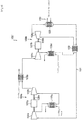
- Fig. 1 is a diagram illustrating a whole construction of a refrigeration system 100 according to an embodiment of the present invention.
- the same elements as those of the above related technique are assigned with the same reference numerals as those of the above related technique, and the same description thereof will be omitted.
- a superconducting device is indicated by an object to be cooled 160, and on the circulation path 150 for cooling the object to be cooled 160, a pump 17 for circulating liquid nitrogen is provided.
- the refrigeration system 100 is capable of cooling based on the same Brayton cycle as the above refrigeration system 100'.
- the refrigeration system 100 is different from the refrigeration system 100' in that a plurality of at least a type of rotating machines, i.e. either the compressor(s) 102 or the expansion turbine(s) 104, are arranged in parallel with one another with regard to the circulation path 101.
- the first unit 109a comprising the compressors 102a and 102b connected to the output shaft 108a at the both ends, respectively, of the common electric motor 107a
- the unit 119a for backup comprising the compressors 112a and 112b connected to the output shaft 118a at the both ends, respectively, of the common electric motor 117a
- the first unit 109a and the backup unit 119a are selectable by operating the switching valves V1 and V2, and the switching valves are operated so that the backup unit 119a is selected when an abnormality of the first unit 109a, which is used during normal operation, is occurred.
- the heat exchanger 103a is shared between the first unit 109a and the backup unit 119a. This is because the heat exchanger 103a is not a rotating machine as the compressor 102a or 102b, and thus the risk of occurrence of abnormality is lower, and the space can be reduced by sharing the heat exchanger between the units.
- switching valves V3 and V4 are provided between the first unit 109a and the backup unit 119a, and the switching valves are operated in accordance with the unit to be in use.
- the second unit 109b comprising the compressor 102c and the expansion turbine 104 connected to the output shaft 108b at the both ends, respectively, of the common electric motor 107b
- the unit 119b for backup comprising the compressor 112c and the expansion turbine 114 connected to the output shaft 118b at the both ends, respectively, of the common electric motor 117b
- the second unit 109b and the backup unit 119b are selectable by operating the switching valves V5 and V6, and the switching valves are operated so that the backup unit 119b is selected when an abnormality of the second unit 109b, which is used during normal operation, is occurred.
- the heat exchanger 103b is shared between the second unit 109b and the backup unit 119b. This is because the heat exchanger 103b is not a rotating machine as the compressor 102c or the expansion turbine 104, and thus the risk of occurrence of abnormality is lower, and the space can be reduced by sharing the heat exchanger between the units.
- switching valves V7 and V8 are provided between the second unit 109b and the backup unit 119b, and the switching valves are operated in accordance with the unit to be in use.
- Fig.2 is a table showing an operation example of switching valves V1 to V8 in the refrigeration system 100 illustrated in Fig. 1 .
- the switching valve V1 is opened to introduce the refrigerant to the first unit 109a side, and the switching valve V2 is closed to shut off the refrigerant to the backup unit 119a side.
- the switching valve V3 and closing the switching valve V4 the refrigerant compressed by the compressor 102a is introduced to the compressor provided on the lower stream side via the heat exchanger 103a.
- the switching valve V5 is opened to introduce the refrigerant to the second unit 109b side, and the switching valve V6 is closed to shut off the refrigerant to the backup unit 119b side.
- the switching valve V7 and closing the switching valve V8 the refrigerant compressed by the compressor 102c is introduced to the expansion turbine 104 provided on the lower stream side via the heat exchanger 103c and the cold heat recovering heat exchanger 106.
- the switching valve V1 is closed to shut off the refrigerant to the first unit 109a side where an abnormality has occurred, and the switching valve V2 is opened to introduce the refrigerant to the backup unit 119a side.
- the switching valve V3 and opening the switching valve V4 the refrigerant compressed by the compressor 112a is introduced to the compressor 112b on the lower stream side via the heat exchanger 103a.
- the open/close statuses of the switching valves V5 to V8 are the same as those indicated in the upper row.
- the switching valves V5 to V8 may be operated in the same manner (Specifically, the switching valve V5 is closed to shut off supply of the refrigerant to the second unit 109b, and the switching valve V6 is opened to introduce the refrigerant to the backup unit 119b side. Then, by closing the switching valve V7 and opening the switching valve V8, the refrigerant passed through the compressor 112c is introduced to the expansion turbine 114 via the heat exchanger 103c and the cold heat recovering heat exchanger 106.).
- Such operation of the switching valves V1 to V8 may be manually carried out when an operator has found an abnormality, or the switching valves may be automatically controlled by a controller comprising a microprocessor, etc. and having a controlling program embedded when an abnormality is detected.
- the expansion turbines 104, 114, the cooling part 105, and the cold heat recovering heat exchanger 106 which are disposed at the side of the object to be cooled and in which the refrigerant having relatively low temperature flows, are accommodated in a cold box 130 capable of being insulated from the outside, to constitute one unit.
- the cold box 130 is configured to pretend intrusion of heat from the outside and to pretend heat loss from the expansion turbines 104, 114, the heat exchanger 105, and the cold heat recovering heat exchanger 106, which have relatively low temperature, by e.g. having a vacuum heat-insulating layer between inner and outer surfaces.
- the compressors 102a, 102b, 102c, and the heat exchangers 103a, 103b, 103c, in which the refrigerant having relatively high temperature, are integrally provided as a compressor unit 140 outside the above cold box 130.
- the cold box 130 is placed at a position closer to the object to be cooled than the compressor unit 140. It is thereby possible to supply the cold heat generated in the cold box 130 to the object to be cooled with a less loss to achieve a good refrigerating efficiency.
- the compressor unit 140 is constituted separated from the cold box 130, it can be dispersively placed at a position apart from the cold box 130.
- the installation space is small around the object to be cooled, by placing only the cold box 130 in the vicinity of the object to be cooled and dispersively placing the compressor unit 140 at a position apart from the object to be cooled, it is possible to install the refrigeration system 100 even in a small installation space.
- a plurality of rotating machines to perform the compression process and the expansion process are arranged in parallel with one another with respect to the circulation path 101 in which the refrigerant flows, whereby even in case of an abnormality (e.g. failure) of one of the plurality of the rotating machines, another one of the plurality of the rotating machines can function as a backup, and it is thereby possible to continue the operation.
- rotating machines tend to have a high risk of abnormality as compared with other components of a refrigeration system.
- by preparing a backup only for a rotating machine having a high risk of abnormality it is possible to increase reliability while suppressing increase in size of the whole system.
- Fig. 3 is a diagram illustrating a whole construction of a refrigeration system 200 according to the first modified example.
- the refrigeration system 200 according to the first modified example is in common with the above example in that it comprises a cold box 130 and a compressor unit 140; however the refrigeration system 200 is different from the above example in that three compressor units 140a, 140b, 140c are provided for one cold box 130. Each of the compressor units 140 is connected to the cold box 130 via a pipe in which the refrigerant flows.
- Fig. 4 is a detailed diagram of the area enclosed by the dashed line in Fig. 3 .
- one of the three structures provided corresponding to the three compressor units shown in Fig. 3 is representatively illustrated, and the construction of the other two structures are the same.
- a box 180 is provided between each of the compressor unit 140 and the cold box 130.
- switching valves 181a and 181b for switching the communication status of the refrigerant inflow/outflow lines between the compressor unit 140 and the cold box 130, the compressor 102c of the second compressor unit 109b, the electric motor 107b and inlet/outlet connecting pipes are provided.
- the refrigerant compressed by the compressors 102a and 102b of the compressor unit 140 are supplied to the box 180, and the refrigerant is additionally compressed by the compressor 102c and then is sent to the heat exchanger 103c vie a compressed gas connecting line.
- the switching valves 181a and 181b are combined with the switching valves V5 and V1, respectively.
- one of the three compressor units 140 is selectively driven to operate the refrigeration system 200.
- the switching valves 181a and 181b in the boxes 180 are operated to switch to the other two compressor units 140 to continue the operation of the refrigeration system 200.
- more than one of the three compressor units 140 may be operated in parallel at the same time. In such a case, as the load per one compressor unit 140 is reduced, the efficiency of the system may be improved; however, the number of the compressor units 140 for backup is reduced in return. Therefore the number of the operating compressor units 140 may be decided in view of the balance.
- the refrigeration system 200 As described above, with the refrigeration system 200 according to the first modified example, as a plurality of compressor units 140 are provided, a higher reliability can be obtained.
- the respective compressor units 140 can be placed apart from the cold box 130, which has to be placed in the vicinity of the object to be cold, whereby it is possible to install the compressor units 140 in installation spaces apart from the cold box 130 to build the refrigeration system 200, which is capable of being installed in a small space, even in a case where a wide area required for the whole system of the refrigeration system cannot be allowed around the object to be cooled.
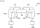
- FIG. 5 is a diagram illustrating a whole construction of a refrigeration system 300 according to the second modified example.
- the refrigeration system 300 according to the second modified example is in common with the above example in that it comprises a cold box 130 and a compressor unit 140; however the refrigeration system 300 is different from the above example in that it has two cold boxes 130a, 130b, and each of the two cold boxes 130 is provided with one compressor unit 140a, 140b. That is, a backup of a set including one cold box 130 and one compressor unit 140 is provided.
- operation is switched so that, for example, during normal operation of the refrigeration system 300, the set including the cold box 130a and the compressor unit 140a are operated, and in case of occurrence of a failure, the set including the cold box 130b and the compressor unit 140b are operated, whereby a continuous operation becomes possible.
- the present invention is applicable to a refrigeration system comprising a refrigeration cycle having a compressor for compressing the refrigerant, a heat exchanger for cooling the refrigerant compressed by the compressor, an expansion turbine for expanding the refrigerant cooled by the heat exchanger to generate cold heat, and a cooling part for cooling an object to be cooled by the cold heat, which are provided in order on a circulation path in which a refrigerant flows.
Applications Claiming Priority (2)
| Application Number | Priority Date | Filing Date | Title |
|---|---|---|---|
| JP2013097143A JP5782065B2 (ja) | 2013-05-02 | 2013-05-02 | 冷凍システム |
| PCT/JP2014/057678 WO2014178240A1 (ja) | 2013-05-02 | 2014-03-20 | 冷凍システム |
Publications (3)
| Publication Number | Publication Date |
|---|---|
| EP2975337A1 EP2975337A1 (en) | 2016-01-20 |
| EP2975337A4 EP2975337A4 (en) | 2016-12-21 |
| EP2975337B1 true EP2975337B1 (en) | 2019-09-18 |
Family
ID=51843375
Family Applications (1)
| Application Number | Title | Priority Date | Filing Date |
|---|---|---|---|
| EP14791203.4A Active EP2975337B1 (en) | 2013-05-02 | 2014-03-20 | Refrigerating system |
Country Status (8)
| Country | Link |
|---|---|
| US (1) | US10168078B2 (ja) |
| EP (1) | EP2975337B1 (ja) |
| JP (1) | JP5782065B2 (ja) |
| KR (1) | KR101762056B1 (ja) |
| CN (1) | CN105209836B (ja) |
| ES (1) | ES2751347T3 (ja) |
| RU (1) | RU2627996C2 (ja) |
| WO (1) | WO2014178240A1 (ja) |
Families Citing this family (20)
| Publication number | Priority date | Publication date | Assignee | Title |
|---|---|---|---|---|
| JP6276000B2 (ja) | 2013-11-11 | 2018-02-07 | 株式会社前川製作所 | 膨張機一体型圧縮機及び冷凍機並びに冷凍機の運転方法 |
| WO2016178272A1 (ja) * | 2015-05-01 | 2016-11-10 | 株式会社前川製作所 | 冷凍機及び冷凍機の運転方法 |
| KR101722607B1 (ko) * | 2015-06-15 | 2017-04-03 | 대우조선해양 주식회사 | 증발가스 처리 시스템 및 방법 |
| KR101722604B1 (ko) * | 2015-06-15 | 2017-04-03 | 대우조선해양 주식회사 | 증발가스 처리 시스템 및 방법 |
| KR101670882B1 (ko) * | 2015-06-15 | 2016-10-31 | 대우조선해양 주식회사 | 증발가스 처리 시스템 및 방법 |
| KR101722606B1 (ko) * | 2015-06-15 | 2017-04-03 | 대우조선해양 주식회사 | 증발가스 처리 시스템 및 방법 |
| KR101670883B1 (ko) * | 2015-06-15 | 2016-10-31 | 대우조선해양 주식회사 | 증발가스 처리 시스템 및 방법 |
| KR101722603B1 (ko) * | 2015-06-15 | 2017-04-03 | 대우조선해양 주식회사 | 증발가스 처리 시스템 및 방법 |
| KR101722605B1 (ko) * | 2015-06-15 | 2017-04-03 | 대우조선해양 주식회사 | 증발가스 처리 시스템 및 방법 |
| KR101722608B1 (ko) * | 2015-06-15 | 2017-04-03 | 대우조선해양 주식회사 | 증발가스 처리 시스템 및 방법 |
| JP6650754B2 (ja) * | 2015-12-25 | 2020-02-19 | 株式会社前川製作所 | 膨張機一体型圧縮機及び冷凍機 |
| US10017032B2 (en) * | 2016-02-16 | 2018-07-10 | The Boeing Company | Thermal management systems and methods |
| CN107560208B (zh) * | 2016-06-30 | 2020-08-04 | 新特能源股份有限公司 | 一种氟利昂制冷系统 |
| WO2018132785A1 (en) * | 2017-01-16 | 2018-07-19 | Praxair Technology, Inc. | Refrigeration cycle for liquid oxygen densification |
| JP2020007986A (ja) * | 2018-07-10 | 2020-01-16 | 住友重機械工業株式会社 | クライオポンプシステム |
| CN110375450A (zh) * | 2019-07-03 | 2019-10-25 | 天津大学 | 一种二氧化碳制冷热泵系统 |
| FR3099815B1 (fr) * | 2019-08-05 | 2021-09-10 | Air Liquide | Dispositif et installation de réfrigération |
| FR3099820B1 (fr) * | 2019-08-05 | 2022-11-04 | Air Liquide | Dispositif et installation de réfrigération |
| WO2022062272A1 (zh) * | 2020-09-27 | 2022-03-31 | 李华玉 | 回热式热力循环与新型回热机械压缩式热泵 |
| JP2022087607A (ja) * | 2020-12-01 | 2022-06-13 | 株式会社前川製作所 | 冷凍システム |
Citations (1)
| Publication number | Priority date | Publication date | Assignee | Title |
|---|---|---|---|---|
| US2737031A (en) * | 1952-02-12 | 1956-03-06 | William A Wulle | Heat energy-converting system and process |
Family Cites Families (21)
| Publication number | Priority date | Publication date | Assignee | Title |
|---|---|---|---|---|
| US3677019A (en) * | 1969-08-01 | 1972-07-18 | Union Carbide Corp | Gas liquefaction process and apparatus |
| US3668884A (en) | 1970-05-05 | 1972-06-13 | William H Nebgen | Refrigeration system, heat recovery system, refrigerated gas compression system and brayton cycle system |
| JPS58217163A (ja) * | 1982-06-10 | 1983-12-17 | 株式会社前川製作所 | 圧縮式冷凍サイクルの冷凍能力増加装置 |
| JPS60207888A (ja) * | 1984-03-31 | 1985-10-19 | 株式会社東芝 | ヘリウム液化装置 |
| JPH0652145B2 (ja) * | 1987-12-12 | 1994-07-06 | 中島 茂 | 超低温冷凍装置 |
| JPH02143057A (ja) * | 1988-11-24 | 1990-06-01 | Hitachi Ltd | 極低温寒冷発生装置 |
| JPH0784961B2 (ja) * | 1990-07-23 | 1995-09-13 | 株式会社日立製作所 | ヘリウム液化冷凍機 |
| JPH05272357A (ja) * | 1992-03-27 | 1993-10-19 | Nippon Sanso Kk | 圧縮機及びその運転方法 |
| JPH06101919A (ja) * | 1992-09-18 | 1994-04-12 | Hitachi Ltd | 極低温冷凍装置 |
| AUPM485694A0 (en) * | 1994-04-05 | 1994-04-28 | Bhp Petroleum Pty. Ltd. | Liquefaction process |
| JPH09329034A (ja) | 1996-06-11 | 1997-12-22 | Ishikawajima Harima Heavy Ind Co Ltd | 閉サイクルガスタービン |
| US6112550A (en) * | 1998-12-30 | 2000-09-05 | Praxair Technology, Inc. | Cryogenic rectification system and hybrid refrigeration generation |
| JP2003148824A (ja) * | 2001-11-13 | 2003-05-21 | Daikin Ind Ltd | 空気調和装置 |
| JP4457928B2 (ja) | 2005-03-15 | 2010-04-28 | ダイキン工業株式会社 | 冷凍装置 |
| JP4241699B2 (ja) * | 2005-09-12 | 2009-03-18 | 三菱重工業株式会社 | 空気冷媒冷凍システム、空気冷媒冷凍システムによるバックアップ方法 |
| US8020406B2 (en) * | 2007-11-05 | 2011-09-20 | David Vandor | Method and system for the small-scale production of liquified natural gas (LNG) from low-pressure gas |
| JP2009210138A (ja) * | 2008-02-29 | 2009-09-17 | Mitsubishi Heavy Ind Ltd | 冷凍サイクルシステム |
| JP4644278B2 (ja) | 2008-10-03 | 2011-03-02 | パナソニック株式会社 | 冷凍サイクル装置 |
| JP5628892B2 (ja) | 2009-04-01 | 2014-11-19 | リナム システムズ、リミテッド | 廃熱空調システム |
| UA97163C2 (ru) * | 2010-03-01 | 2012-01-10 | Восточноукраинский Национальный Университет Имени Владимира Даля | Воздушная холодильная машина крайнюка |
| EP2769159B1 (en) | 2011-10-21 | 2018-01-10 | Single Buoy Moorings, Inc. | Multi nitrogen expansion process for lng production |
-
2013
- 2013-05-02 JP JP2013097143A patent/JP5782065B2/ja active Active
-
2014
- 2014-03-20 US US14/888,235 patent/US10168078B2/en active Active
- 2014-03-20 ES ES14791203T patent/ES2751347T3/es active Active
- 2014-03-20 WO PCT/JP2014/057678 patent/WO2014178240A1/ja active Application Filing
- 2014-03-20 RU RU2015151396A patent/RU2627996C2/ru active
- 2014-03-20 CN CN201480024722.9A patent/CN105209836B/zh active Active
- 2014-03-20 KR KR1020157033129A patent/KR101762056B1/ko active IP Right Grant
- 2014-03-20 EP EP14791203.4A patent/EP2975337B1/en active Active
Patent Citations (1)
| Publication number | Priority date | Publication date | Assignee | Title |
|---|---|---|---|---|
| US2737031A (en) * | 1952-02-12 | 1956-03-06 | William A Wulle | Heat energy-converting system and process |
Also Published As
| Publication number | Publication date |
|---|---|
| RU2015151396A (ru) | 2017-06-07 |
| ES2751347T3 (es) | 2020-03-31 |
| EP2975337A1 (en) | 2016-01-20 |
| KR20160002990A (ko) | 2016-01-08 |
| US20160076793A1 (en) | 2016-03-17 |
| EP2975337A4 (en) | 2016-12-21 |
| JP5782065B2 (ja) | 2015-09-24 |
| US10168078B2 (en) | 2019-01-01 |
| CN105209836A (zh) | 2015-12-30 |
| JP2014219125A (ja) | 2014-11-20 |
| RU2627996C2 (ru) | 2017-08-14 |
| CN105209836B (zh) | 2017-08-04 |
| WO2014178240A1 (ja) | 2014-11-06 |
| KR101762056B1 (ko) | 2017-07-26 |
Similar Documents
| Publication | Publication Date | Title |
|---|---|---|
| EP2975337B1 (en) | Refrigerating system | |
| EP3325898B1 (en) | Hydronic system for combining free cooling and mechanical cooling | |
| JP6571491B2 (ja) | ヒートポンプ | |
| JP5817775B2 (ja) | チラー装置 | |
| JP5530904B2 (ja) | ヒートポンプ式高温水発生器 | |
| EP3276279B1 (en) | Heat pump hot-water-supply outdoor device, and hot-water-supply device | |
| EP3514461B1 (en) | Refrigeration cycle apparatus | |
| JP6569096B2 (ja) | 開放循環冷却システムおよび運転休止時の熱交換器のチューブ防食方法 | |
| US20130008199A1 (en) | Virtual moveable endcap non-reversing heater chiller system | |
| KR102061757B1 (ko) | 모듈형 하이브리드 실외기 장치 | |
| JP6118065B2 (ja) | 水冷式空調システム及びその運転制御方法 | |
| WO2018147363A1 (ja) | パッケージユニット及びパッケージユニットのメンテナンス方法 | |
| JP2019095079A (ja) | 高温超電導電力機器用冷却システム及びその運転方法 | |
| CN110838687B (zh) | 大型电力电子设备高可靠性闭式风冷散热系统和散热方法 | |
| JP5402164B2 (ja) | 冷凍サイクル装置 | |
| JP2016024672A (ja) | 冷却装置 | |
| WO2015122167A1 (ja) | 空気調和機 | |
| KR102029292B1 (ko) | 모듈형 실외기 장치 | |
| WO2018003099A1 (ja) | 冷却装置 | |
| WO2018216112A1 (ja) | 冷凍サイクル装置 | |
| JP2009299971A (ja) | 冷却加熱塔システム | |
| JP2017116122A (ja) | 熱交換装置 |
Legal Events
| Date | Code | Title | Description |
|---|---|---|---|
| PUAI | Public reference made under article 153(3) epc to a published international application that has entered the european phase |
Free format text: ORIGINAL CODE: 0009012 |
|
| 17P | Request for examination filed |
Effective date: 20151013 |
|
| AK | Designated contracting states |
Kind code of ref document: A1 Designated state(s): AL AT BE BG CH CY CZ DE DK EE ES FI FR GB GR HR HU IE IS IT LI LT LU LV MC MK MT NL NO PL PT RO RS SE SI SK SM TR |
|
| AX | Request for extension of the european patent |
Extension state: BA ME |
|
| DAX | Request for extension of the european patent (deleted) | ||
| A4 | Supplementary search report drawn up and despatched |
Effective date: 20161122 |
|
| RIC1 | Information provided on ipc code assigned before grant |
Ipc: F25B 27/00 20060101ALI20161116BHEP Ipc: F25B 25/00 20060101ALI20161116BHEP Ipc: F25B 11/02 20060101ALI20161116BHEP Ipc: F25B 6/04 20060101ALI20161116BHEP Ipc: F25B 9/10 20060101ALI20161116BHEP Ipc: F25B 1/10 20060101ALI20161116BHEP Ipc: F25B 9/06 20060101AFI20161116BHEP Ipc: F25B 41/04 20060101ALI20161116BHEP Ipc: F25B 9/00 20060101ALI20161116BHEP |
|
| STAA | Information on the status of an ep patent application or granted ep patent |
Free format text: STATUS: EXAMINATION IS IN PROGRESS |
|
| 17Q | First examination report despatched |
Effective date: 20171016 |
|
| GRAP | Despatch of communication of intention to grant a patent |
Free format text: ORIGINAL CODE: EPIDOSNIGR1 |
|
| STAA | Information on the status of an ep patent application or granted ep patent |
Free format text: STATUS: GRANT OF PATENT IS INTENDED |
|
| INTG | Intention to grant announced |
Effective date: 20181205 |
|
| GRAJ | Information related to disapproval of communication of intention to grant by the applicant or resumption of examination proceedings by the epo deleted |
Free format text: ORIGINAL CODE: EPIDOSDIGR1 |
|
| STAA | Information on the status of an ep patent application or granted ep patent |
Free format text: STATUS: EXAMINATION IS IN PROGRESS |
|
| GRAP | Despatch of communication of intention to grant a patent |
Free format text: ORIGINAL CODE: EPIDOSNIGR1 |
|
| STAA | Information on the status of an ep patent application or granted ep patent |
Free format text: STATUS: GRANT OF PATENT IS INTENDED |
|
| INTG | Intention to grant announced |
Effective date: 20190423 |
|
| GRAS | Grant fee paid |
Free format text: ORIGINAL CODE: EPIDOSNIGR3 |
|
| GRAA | (expected) grant |
Free format text: ORIGINAL CODE: 0009210 |
|
| STAA | Information on the status of an ep patent application or granted ep patent |
Free format text: STATUS: THE PATENT HAS BEEN GRANTED |
|
| AK | Designated contracting states |
Kind code of ref document: B1 Designated state(s): AL AT BE BG CH CY CZ DE DK EE ES FI FR GB GR HR HU IE IS IT LI LT LU LV MC MK MT NL NO PL PT RO RS SE SI SK SM TR |
|
| REG | Reference to a national code |
Ref country code: GB Ref legal event code: FG4D |
|
| REG | Reference to a national code |
Ref country code: CH Ref legal event code: EP |
|
| REG | Reference to a national code |
Ref country code: DE Ref legal event code: R096 Ref document number: 602014053924 Country of ref document: DE |
|
| REG | Reference to a national code |
Ref country code: AT Ref legal event code: REF Ref document number: 1181816 Country of ref document: AT Kind code of ref document: T Effective date: 20191015 |
|
| REG | Reference to a national code |
Ref country code: IE Ref legal event code: FG4D |
|
| REG | Reference to a national code |
Ref country code: CH Ref legal event code: NV Representative=s name: VALIPAT S.A. C/O BOVARD SA NEUCHATEL, CH |
|
| REG | Reference to a national code |
Ref country code: NL Ref legal event code: MP Effective date: 20190918 |
|
| PG25 | Lapsed in a contracting state [announced via postgrant information from national office to epo] |
Ref country code: SE Free format text: LAPSE BECAUSE OF FAILURE TO SUBMIT A TRANSLATION OF THE DESCRIPTION OR TO PAY THE FEE WITHIN THE PRESCRIBED TIME-LIMIT Effective date: 20190918 Ref country code: HR Free format text: LAPSE BECAUSE OF FAILURE TO SUBMIT A TRANSLATION OF THE DESCRIPTION OR TO PAY THE FEE WITHIN THE PRESCRIBED TIME-LIMIT Effective date: 20190918 Ref country code: LT Free format text: LAPSE BECAUSE OF FAILURE TO SUBMIT A TRANSLATION OF THE DESCRIPTION OR TO PAY THE FEE WITHIN THE PRESCRIBED TIME-LIMIT Effective date: 20190918 Ref country code: FI Free format text: LAPSE BECAUSE OF FAILURE TO SUBMIT A TRANSLATION OF THE DESCRIPTION OR TO PAY THE FEE WITHIN THE PRESCRIBED TIME-LIMIT Effective date: 20190918 Ref country code: NO Free format text: LAPSE BECAUSE OF FAILURE TO SUBMIT A TRANSLATION OF THE DESCRIPTION OR TO PAY THE FEE WITHIN THE PRESCRIBED TIME-LIMIT Effective date: 20191218 Ref country code: BG Free format text: LAPSE BECAUSE OF FAILURE TO SUBMIT A TRANSLATION OF THE DESCRIPTION OR TO PAY THE FEE WITHIN THE PRESCRIBED TIME-LIMIT Effective date: 20191218 |
|
| REG | Reference to a national code |
Ref country code: LT Ref legal event code: MG4D |
|
| PG25 | Lapsed in a contracting state [announced via postgrant information from national office to epo] |
Ref country code: AL Free format text: LAPSE BECAUSE OF FAILURE TO SUBMIT A TRANSLATION OF THE DESCRIPTION OR TO PAY THE FEE WITHIN THE PRESCRIBED TIME-LIMIT Effective date: 20190918 Ref country code: LV Free format text: LAPSE BECAUSE OF FAILURE TO SUBMIT A TRANSLATION OF THE DESCRIPTION OR TO PAY THE FEE WITHIN THE PRESCRIBED TIME-LIMIT Effective date: 20190918 Ref country code: GR Free format text: LAPSE BECAUSE OF FAILURE TO SUBMIT A TRANSLATION OF THE DESCRIPTION OR TO PAY THE FEE WITHIN THE PRESCRIBED TIME-LIMIT Effective date: 20191219 Ref country code: RS Free format text: LAPSE BECAUSE OF FAILURE TO SUBMIT A TRANSLATION OF THE DESCRIPTION OR TO PAY THE FEE WITHIN THE PRESCRIBED TIME-LIMIT Effective date: 20190918 |
|
| REG | Reference to a national code |
Ref country code: ES Ref legal event code: FG2A Ref document number: 2751347 Country of ref document: ES Kind code of ref document: T3 Effective date: 20200331 |
|
| REG | Reference to a national code |
Ref country code: AT Ref legal event code: MK05 Ref document number: 1181816 Country of ref document: AT Kind code of ref document: T Effective date: 20190918 |
|
| PG25 | Lapsed in a contracting state [announced via postgrant information from national office to epo] |
Ref country code: IT Free format text: LAPSE BECAUSE OF FAILURE TO SUBMIT A TRANSLATION OF THE DESCRIPTION OR TO PAY THE FEE WITHIN THE PRESCRIBED TIME-LIMIT Effective date: 20190918 Ref country code: RO Free format text: LAPSE BECAUSE OF FAILURE TO SUBMIT A TRANSLATION OF THE DESCRIPTION OR TO PAY THE FEE WITHIN THE PRESCRIBED TIME-LIMIT Effective date: 20190918 Ref country code: NL Free format text: LAPSE BECAUSE OF FAILURE TO SUBMIT A TRANSLATION OF THE DESCRIPTION OR TO PAY THE FEE WITHIN THE PRESCRIBED TIME-LIMIT Effective date: 20190918 Ref country code: AT Free format text: LAPSE BECAUSE OF FAILURE TO SUBMIT A TRANSLATION OF THE DESCRIPTION OR TO PAY THE FEE WITHIN THE PRESCRIBED TIME-LIMIT Effective date: 20190918 Ref country code: PT Free format text: LAPSE BECAUSE OF FAILURE TO SUBMIT A TRANSLATION OF THE DESCRIPTION OR TO PAY THE FEE WITHIN THE PRESCRIBED TIME-LIMIT Effective date: 20200120 Ref country code: EE Free format text: LAPSE BECAUSE OF FAILURE TO SUBMIT A TRANSLATION OF THE DESCRIPTION OR TO PAY THE FEE WITHIN THE PRESCRIBED TIME-LIMIT Effective date: 20190918 Ref country code: PL Free format text: LAPSE BECAUSE OF FAILURE TO SUBMIT A TRANSLATION OF THE DESCRIPTION OR TO PAY THE FEE WITHIN THE PRESCRIBED TIME-LIMIT Effective date: 20190918 |
|
| PG25 | Lapsed in a contracting state [announced via postgrant information from national office to epo] |
Ref country code: SK Free format text: LAPSE BECAUSE OF FAILURE TO SUBMIT A TRANSLATION OF THE DESCRIPTION OR TO PAY THE FEE WITHIN THE PRESCRIBED TIME-LIMIT Effective date: 20190918 Ref country code: IS Free format text: LAPSE BECAUSE OF FAILURE TO SUBMIT A TRANSLATION OF THE DESCRIPTION OR TO PAY THE FEE WITHIN THE PRESCRIBED TIME-LIMIT Effective date: 20200224 Ref country code: SM Free format text: LAPSE BECAUSE OF FAILURE TO SUBMIT A TRANSLATION OF THE DESCRIPTION OR TO PAY THE FEE WITHIN THE PRESCRIBED TIME-LIMIT Effective date: 20190918 Ref country code: CZ Free format text: LAPSE BECAUSE OF FAILURE TO SUBMIT A TRANSLATION OF THE DESCRIPTION OR TO PAY THE FEE WITHIN THE PRESCRIBED TIME-LIMIT Effective date: 20190918 |
|
| REG | Reference to a national code |
Ref country code: DE Ref legal event code: R097 Ref document number: 602014053924 Country of ref document: DE |
|
| PLBE | No opposition filed within time limit |
Free format text: ORIGINAL CODE: 0009261 |
|
| STAA | Information on the status of an ep patent application or granted ep patent |
Free format text: STATUS: NO OPPOSITION FILED WITHIN TIME LIMIT |
|
| PG2D | Information on lapse in contracting state deleted |
Ref country code: IS |
|
| PG25 | Lapsed in a contracting state [announced via postgrant information from national office to epo] |
Ref country code: DK Free format text: LAPSE BECAUSE OF FAILURE TO SUBMIT A TRANSLATION OF THE DESCRIPTION OR TO PAY THE FEE WITHIN THE PRESCRIBED TIME-LIMIT Effective date: 20190918 Ref country code: IS Free format text: LAPSE BECAUSE OF FAILURE TO SUBMIT A TRANSLATION OF THE DESCRIPTION OR TO PAY THE FEE WITHIN THE PRESCRIBED TIME-LIMIT Effective date: 20200119 |
|
| 26N | No opposition filed |
Effective date: 20200619 |
|
| PG25 | Lapsed in a contracting state [announced via postgrant information from national office to epo] |
Ref country code: SI Free format text: LAPSE BECAUSE OF FAILURE TO SUBMIT A TRANSLATION OF THE DESCRIPTION OR TO PAY THE FEE WITHIN THE PRESCRIBED TIME-LIMIT Effective date: 20190918 |
|
| PG25 | Lapsed in a contracting state [announced via postgrant information from national office to epo] |
Ref country code: MC Free format text: LAPSE BECAUSE OF FAILURE TO SUBMIT A TRANSLATION OF THE DESCRIPTION OR TO PAY THE FEE WITHIN THE PRESCRIBED TIME-LIMIT Effective date: 20190918 |
|
| REG | Reference to a national code |
Ref country code: BE Ref legal event code: MM Effective date: 20200331 |
|
| PG25 | Lapsed in a contracting state [announced via postgrant information from national office to epo] |
Ref country code: LU Free format text: LAPSE BECAUSE OF NON-PAYMENT OF DUE FEES Effective date: 20200320 |
|
| PG25 | Lapsed in a contracting state [announced via postgrant information from national office to epo] |
Ref country code: FR Free format text: LAPSE BECAUSE OF NON-PAYMENT OF DUE FEES Effective date: 20200331 Ref country code: IE Free format text: LAPSE BECAUSE OF NON-PAYMENT OF DUE FEES Effective date: 20200320 |
|
| PG25 | Lapsed in a contracting state [announced via postgrant information from national office to epo] |
Ref country code: BE Free format text: LAPSE BECAUSE OF NON-PAYMENT OF DUE FEES Effective date: 20200331 |
|
| GBPC | Gb: european patent ceased through non-payment of renewal fee |
Effective date: 20200320 |
|
| PG25 | Lapsed in a contracting state [announced via postgrant information from national office to epo] |
Ref country code: GB Free format text: LAPSE BECAUSE OF NON-PAYMENT OF DUE FEES Effective date: 20200320 |
|
| PGFP | Annual fee paid to national office [announced via postgrant information from national office to epo] |
Ref country code: DE Payment date: 20220203 Year of fee payment: 9 Ref country code: CH Payment date: 20220215 Year of fee payment: 9 |
|
| PG25 | Lapsed in a contracting state [announced via postgrant information from national office to epo] |
Ref country code: TR Free format text: LAPSE BECAUSE OF FAILURE TO SUBMIT A TRANSLATION OF THE DESCRIPTION OR TO PAY THE FEE WITHIN THE PRESCRIBED TIME-LIMIT Effective date: 20190918 Ref country code: MT Free format text: LAPSE BECAUSE OF FAILURE TO SUBMIT A TRANSLATION OF THE DESCRIPTION OR TO PAY THE FEE WITHIN THE PRESCRIBED TIME-LIMIT Effective date: 20190918 Ref country code: CY Free format text: LAPSE BECAUSE OF FAILURE TO SUBMIT A TRANSLATION OF THE DESCRIPTION OR TO PAY THE FEE WITHIN THE PRESCRIBED TIME-LIMIT Effective date: 20190918 |
|
| PG25 | Lapsed in a contracting state [announced via postgrant information from national office to epo] |
Ref country code: MK Free format text: LAPSE BECAUSE OF FAILURE TO SUBMIT A TRANSLATION OF THE DESCRIPTION OR TO PAY THE FEE WITHIN THE PRESCRIBED TIME-LIMIT Effective date: 20190918 |
|
| PGFP | Annual fee paid to national office [announced via postgrant information from national office to epo] |
Ref country code: ES Payment date: 20220401 Year of fee payment: 9 |
|
| REG | Reference to a national code |
Ref country code: DE Ref legal event code: R119 Ref document number: 602014053924 Country of ref document: DE |
|
| REG | Reference to a national code |
Ref country code: CH Ref legal event code: PL |
|
| PG25 | Lapsed in a contracting state [announced via postgrant information from national office to epo] |
Ref country code: LI Free format text: LAPSE BECAUSE OF NON-PAYMENT OF DUE FEES Effective date: 20230331 Ref country code: DE Free format text: LAPSE BECAUSE OF NON-PAYMENT OF DUE FEES Effective date: 20231003 Ref country code: CH Free format text: LAPSE BECAUSE OF NON-PAYMENT OF DUE FEES Effective date: 20230331 |