EP2965931A1 - Klimaanlagevorrichtung für fahrzeug - Google Patents
Klimaanlagevorrichtung für fahrzeug Download PDFInfo
- Publication number
- EP2965931A1 EP2965931A1 EP14759689.4A EP14759689A EP2965931A1 EP 2965931 A1 EP2965931 A1 EP 2965931A1 EP 14759689 A EP14759689 A EP 14759689A EP 2965931 A1 EP2965931 A1 EP 2965931A1
- Authority
- EP
- European Patent Office
- Prior art keywords
- coolant
- flow rate
- refrigerant
- temperature
- air conditioning
- Prior art date
- Legal status (The legal status is an assumption and is not a legal conclusion. Google has not performed a legal analysis and makes no representation as to the accuracy of the status listed.)
- Withdrawn
Links
- 238000004378 air conditioning Methods 0.000 title claims abstract description 78
- 239000003507 refrigerant Substances 0.000 claims abstract description 86
- 239000002826 coolant Substances 0.000 claims description 121
- XLYOFNOQVPJJNP-UHFFFAOYSA-N water Substances O XLYOFNOQVPJJNP-UHFFFAOYSA-N 0.000 claims description 75
- 238000001816 cooling Methods 0.000 claims description 27
- 239000000110 cooling liquid Substances 0.000 abstract 4
- 238000010438 heat treatment Methods 0.000 description 54
- 238000000034 method Methods 0.000 description 27
- 230000000052 comparative effect Effects 0.000 description 9
- 238000007791 dehumidification Methods 0.000 description 7
- 238000010586 diagram Methods 0.000 description 6
- 239000002918 waste heat Substances 0.000 description 6
- 230000000694 effects Effects 0.000 description 4
- 230000003252 repetitive effect Effects 0.000 description 3
- 230000001133 acceleration Effects 0.000 description 1
- 238000002485 combustion reaction Methods 0.000 description 1
- 230000007423 decrease Effects 0.000 description 1
- 238000009423 ventilation Methods 0.000 description 1
Images


Classifications
-
- B—PERFORMING OPERATIONS; TRANSPORTING
- B60—VEHICLES IN GENERAL
- B60H—ARRANGEMENTS OF HEATING, COOLING, VENTILATING OR OTHER AIR-TREATING DEVICES SPECIALLY ADAPTED FOR PASSENGER OR GOODS SPACES OF VEHICLES
- B60H1/00—Heating, cooling or ventilating [HVAC] devices
- B60H1/00642—Control systems or circuits; Control members or indication devices for heating, cooling or ventilating devices
- B60H1/00814—Control systems or circuits characterised by their output, for controlling particular components of the heating, cooling or ventilating installation
- B60H1/00878—Control systems or circuits characterised by their output, for controlling particular components of the heating, cooling or ventilating installation the components being temperature regulating devices
- B60H1/00899—Controlling the flow of liquid in a heat pump system
- B60H1/00921—Controlling the flow of liquid in a heat pump system where the flow direction of the refrigerant does not change and there is an extra subcondenser, e.g. in an air duct
-
- B—PERFORMING OPERATIONS; TRANSPORTING
- B60—VEHICLES IN GENERAL
- B60H—ARRANGEMENTS OF HEATING, COOLING, VENTILATING OR OTHER AIR-TREATING DEVICES SPECIALLY ADAPTED FOR PASSENGER OR GOODS SPACES OF VEHICLES
- B60H1/00—Heating, cooling or ventilating [HVAC] devices
- B60H1/32—Cooling devices
- B60H1/3204—Cooling devices using compression
- B60H1/3205—Control means therefor
- B60H1/3213—Control means therefor for increasing the efficiency in a vehicle heat pump
-
- B—PERFORMING OPERATIONS; TRANSPORTING
- B60—VEHICLES IN GENERAL
- B60H—ARRANGEMENTS OF HEATING, COOLING, VENTILATING OR OTHER AIR-TREATING DEVICES SPECIALLY ADAPTED FOR PASSENGER OR GOODS SPACES OF VEHICLES
- B60H1/00—Heating, cooling or ventilating [HVAC] devices
- B60H1/00007—Combined heating, ventilating, or cooling devices
-
- F—MECHANICAL ENGINEERING; LIGHTING; HEATING; WEAPONS; BLASTING
- F25—REFRIGERATION OR COOLING; COMBINED HEATING AND REFRIGERATION SYSTEMS; HEAT PUMP SYSTEMS; MANUFACTURE OR STORAGE OF ICE; LIQUEFACTION SOLIDIFICATION OF GASES
- F25B—REFRIGERATION MACHINES, PLANTS OR SYSTEMS; COMBINED HEATING AND REFRIGERATION SYSTEMS; HEAT PUMP SYSTEMS
- F25B5/00—Compression machines, plants or systems, with several evaporator circuits, e.g. for varying refrigerating capacity
- F25B5/02—Compression machines, plants or systems, with several evaporator circuits, e.g. for varying refrigerating capacity arranged in parallel
-
- F—MECHANICAL ENGINEERING; LIGHTING; HEATING; WEAPONS; BLASTING
- F25—REFRIGERATION OR COOLING; COMBINED HEATING AND REFRIGERATION SYSTEMS; HEAT PUMP SYSTEMS; MANUFACTURE OR STORAGE OF ICE; LIQUEFACTION SOLIDIFICATION OF GASES
- F25B—REFRIGERATION MACHINES, PLANTS OR SYSTEMS; COMBINED HEATING AND REFRIGERATION SYSTEMS; HEAT PUMP SYSTEMS
- F25B6/00—Compression machines, plants or systems, with several condenser circuits
- F25B6/04—Compression machines, plants or systems, with several condenser circuits arranged in series
-
- F—MECHANICAL ENGINEERING; LIGHTING; HEATING; WEAPONS; BLASTING
- F25—REFRIGERATION OR COOLING; COMBINED HEATING AND REFRIGERATION SYSTEMS; HEAT PUMP SYSTEMS; MANUFACTURE OR STORAGE OF ICE; LIQUEFACTION SOLIDIFICATION OF GASES
- F25B—REFRIGERATION MACHINES, PLANTS OR SYSTEMS; COMBINED HEATING AND REFRIGERATION SYSTEMS; HEAT PUMP SYSTEMS
- F25B2339/00—Details of evaporators; Details of condensers
- F25B2339/04—Details of condensers
- F25B2339/047—Water-cooled condensers
-
- F—MECHANICAL ENGINEERING; LIGHTING; HEATING; WEAPONS; BLASTING
- F25—REFRIGERATION OR COOLING; COMBINED HEATING AND REFRIGERATION SYSTEMS; HEAT PUMP SYSTEMS; MANUFACTURE OR STORAGE OF ICE; LIQUEFACTION SOLIDIFICATION OF GASES
- F25B—REFRIGERATION MACHINES, PLANTS OR SYSTEMS; COMBINED HEATING AND REFRIGERATION SYSTEMS; HEAT PUMP SYSTEMS
- F25B25/00—Machines, plants or systems, using a combination of modes of operation covered by two or more of the groups F25B1/00 - F25B23/00
- F25B25/005—Machines, plants or systems, using a combination of modes of operation covered by two or more of the groups F25B1/00 - F25B23/00 using primary and secondary systems
-
- F—MECHANICAL ENGINEERING; LIGHTING; HEATING; WEAPONS; BLASTING
- F25—REFRIGERATION OR COOLING; COMBINED HEATING AND REFRIGERATION SYSTEMS; HEAT PUMP SYSTEMS; MANUFACTURE OR STORAGE OF ICE; LIQUEFACTION SOLIDIFICATION OF GASES
- F25B—REFRIGERATION MACHINES, PLANTS OR SYSTEMS; COMBINED HEATING AND REFRIGERATION SYSTEMS; HEAT PUMP SYSTEMS
- F25B2600/00—Control issues
- F25B2600/13—Pump speed control
-
- F—MECHANICAL ENGINEERING; LIGHTING; HEATING; WEAPONS; BLASTING
- F25—REFRIGERATION OR COOLING; COMBINED HEATING AND REFRIGERATION SYSTEMS; HEAT PUMP SYSTEMS; MANUFACTURE OR STORAGE OF ICE; LIQUEFACTION SOLIDIFICATION OF GASES
- F25B—REFRIGERATION MACHINES, PLANTS OR SYSTEMS; COMBINED HEATING AND REFRIGERATION SYSTEMS; HEAT PUMP SYSTEMS
- F25B2600/00—Control issues
- F25B2600/25—Control of valves
- F25B2600/2519—On-off valves
-
- F—MECHANICAL ENGINEERING; LIGHTING; HEATING; WEAPONS; BLASTING
- F25—REFRIGERATION OR COOLING; COMBINED HEATING AND REFRIGERATION SYSTEMS; HEAT PUMP SYSTEMS; MANUFACTURE OR STORAGE OF ICE; LIQUEFACTION SOLIDIFICATION OF GASES
- F25B—REFRIGERATION MACHINES, PLANTS OR SYSTEMS; COMBINED HEATING AND REFRIGERATION SYSTEMS; HEAT PUMP SYSTEMS
- F25B27/00—Machines, plants or systems, using particular sources of energy
- F25B27/02—Machines, plants or systems, using particular sources of energy using waste heat, e.g. from internal-combustion engines
-
- F—MECHANICAL ENGINEERING; LIGHTING; HEATING; WEAPONS; BLASTING
- F25—REFRIGERATION OR COOLING; COMBINED HEATING AND REFRIGERATION SYSTEMS; HEAT PUMP SYSTEMS; MANUFACTURE OR STORAGE OF ICE; LIQUEFACTION SOLIDIFICATION OF GASES
- F25B—REFRIGERATION MACHINES, PLANTS OR SYSTEMS; COMBINED HEATING AND REFRIGERATION SYSTEMS; HEAT PUMP SYSTEMS
- F25B2700/00—Sensing or detecting of parameters; Sensors therefor
- F25B2700/21—Temperatures
- F25B2700/2116—Temperatures of a condenser
- F25B2700/21161—Temperatures of a condenser of the fluid heated by the condenser
-
- F—MECHANICAL ENGINEERING; LIGHTING; HEATING; WEAPONS; BLASTING
- F25—REFRIGERATION OR COOLING; COMBINED HEATING AND REFRIGERATION SYSTEMS; HEAT PUMP SYSTEMS; MANUFACTURE OR STORAGE OF ICE; LIQUEFACTION SOLIDIFICATION OF GASES
- F25B—REFRIGERATION MACHINES, PLANTS OR SYSTEMS; COMBINED HEATING AND REFRIGERATION SYSTEMS; HEAT PUMP SYSTEMS
- F25B2700/00—Sensing or detecting of parameters; Sensors therefor
- F25B2700/21—Temperatures
- F25B2700/2117—Temperatures of an evaporator
-
- F—MECHANICAL ENGINEERING; LIGHTING; HEATING; WEAPONS; BLASTING
- F25—REFRIGERATION OR COOLING; COMBINED HEATING AND REFRIGERATION SYSTEMS; HEAT PUMP SYSTEMS; MANUFACTURE OR STORAGE OF ICE; LIQUEFACTION SOLIDIFICATION OF GASES
- F25B—REFRIGERATION MACHINES, PLANTS OR SYSTEMS; COMBINED HEATING AND REFRIGERATION SYSTEMS; HEAT PUMP SYSTEMS
- F25B29/00—Combined heating and refrigeration systems, e.g. operating alternately or simultaneously
- F25B29/003—Combined heating and refrigeration systems, e.g. operating alternately or simultaneously of the compression type system
-
- Y—GENERAL TAGGING OF NEW TECHNOLOGICAL DEVELOPMENTS; GENERAL TAGGING OF CROSS-SECTIONAL TECHNOLOGIES SPANNING OVER SEVERAL SECTIONS OF THE IPC; TECHNICAL SUBJECTS COVERED BY FORMER USPC CROSS-REFERENCE ART COLLECTIONS [XRACs] AND DIGESTS
- Y02—TECHNOLOGIES OR APPLICATIONS FOR MITIGATION OR ADAPTATION AGAINST CLIMATE CHANGE
- Y02A—TECHNOLOGIES FOR ADAPTATION TO CLIMATE CHANGE
- Y02A30/00—Adapting or protecting infrastructure or their operation
- Y02A30/27—Relating to heating, ventilation or air conditioning [HVAC] technologies
- Y02A30/274—Relating to heating, ventilation or air conditioning [HVAC] technologies using waste energy, e.g. from internal combustion engine
Definitions
- the present invention relates to a vehicle air conditioning apparatus.
- a vehicle air conditioning apparatus which provides cooling or heating for the vehicle interior using a heat pump (e.g., see PTL 1).
- a vehicle air conditioning apparatus that provides heating for the vehicle interior using heat of an engine coolant.
- a vehicle air conditioning apparatus which heats an engine coolant with a high-temperature and high-pressure refrigerant of a heat pump and provides heating for the vehicle interior using this coolant (e.g., FIG 18 of PTL 1).
- the conventional vehicle air conditioning apparatus that provides heating for the vehicle interior using heat of an engine coolant has a problem that heating of the vehicle interior is not possible when the temperature of the engine coolant is not high.
- the conventional vehicle air conditioning apparatus which further heats the engine coolant with the high-temperature and high-pressure refrigerant of the heat pump and provides heating for the vehicle interior with this coolant, can provide heating for the vehicle interior even in a situation in which the temperature of the engine coolant does not become so high.
- the heating efficiency of such a vehicle air conditioning apparatus deteriorates (details thereof will be described later using FIGS. 2A and 2B , and FIGS. 3A and 3B ).
- Such a problem may likewise occur when waste heat is available from heat-generating parts other than the engine such as a secondary battery for supplying driving power or driving electric motor in an electric vehicle and used for heating.
- An object of the present invention is to provide a vehicle air conditioning apparatus capable of providing heating for the vehicle interior with high efficiency even when an outside air temperature is low and not much waste heat is available from heat-generating parts of the vehicle.
- a vehicle air conditioning apparatus includes: a heater core through which a high-temperature coolant flows and which gives heat to air to be sent into a vehicle interior; a first water-refrigerant heat exchanger that exchanges heat between the coolant and a high-temperature and high-pressure refrigerant in a heat pump to condense the refrigerant; a flow rate adjusting section that adjusts a flow rate of the coolant that flows through the first water-refrigerant heat exchanger and the heater core; and a control section that performs air conditioning control, in which the control section controls the flow rate adjusting section to set the flow rate of the coolant to a flow rate lower than a first flow rate for a predetermined time period from starting up of the heat pump, the flow rate being referred to as a second flow rate, the first flow rate being used during a standard operation.
- the present invention it is possible to provide heating for the vehicle interior with high efficiency even when an outside temperature is low and not much waste heat is available from a heat-generating part of the vehicle.
- a basic configuration focused by the present inventor et al. will be described as a configuration of a vehicle air conditioning apparatus capable of providing heating for the vehicle interior with high efficiency even when waste heat is available not so much from heat-generating parts of the vehicle first.
- FIG. 1 illustrates a basic configuration serving as a premise for the vehicle air conditioning apparatus according to the embodiment of the present invention.
- a water circuit denotes a path through which a coolant flows.
- Vehicle air conditioning apparatus 100 in FIG. 1 is an apparatus mounted on a vehicle including a heat-generating part (e.g., engine (internal combustion engine)) for providing heating, dehumidification and cooling for the vehicle interior.
- a heat-generating part e.g., engine (internal combustion engine)
- engine internal combustion engine
- Vehicle air conditioning apparatus 100 is provided with compressor 38, engine cooling section 40, three-way valves 42 and 43, heater core 44, evaporator 48, expansion valve 37, outdoor condenser 39, sub-evaporator (corresponding to second water-refrigerant heat exchanger) 11, sub-condenser (corresponding to first water-refrigerant heat exchanger) 12, on-off valve 13, electromagnetic-valve-equipped expansion valve 14, water pump (corresponding to flow rate adjusting section) 16, and coolant and coolant pipes connecting between these components.
- Heater core 44 and evaporator 48 are arranged in an intake air passage of a heating, ventilation, and air conditioning (HVAC) 70.
- HVAC 70 is provided with blower fan F1 through which intake air flows.
- Compressor 38 is driven by electric power, compresses a suctioned refrigerant to a high temperature and high pressure, and discharges the refrigerant.
- Engine cooling section 40 is provided with a water jacket that circulates a coolant around the engine and water pump 17 that circulates the coolant through the water jacket, and discharges heat from the engine into the coolant that flows through the water jacket.
- Water pump 17 rotates by engine power, for example.
- Engine cooling section 40 may be provided with a radiator that discharges heat into outside air when the amount of waste heat of the engine increases.
- Heater core 44 is a device that exchanges heat between the coolant and air and is placed in an intake air passage of HVAC 70 that supplies air into the vehicle interior. Heater core 44 is supplied with the heated coolant and radiates heat into the intake air to be sent into the vehicle interior during heating operation.
- Three-way valves 42 and 43 are valves that switch whether the passage of the coolant of engine cooling section 40 communicates with sub-evaporator 11 or communicates with heater core 44. Note that the section that performs this switching is not limited to the three-way valves, but can be constructed of a combination of a plurality of valves. Three-way valves 42 and 43 can perform the above-described switching under electrical control, for example.
- Evaporator 48 is a device that exchanges heat between a low-temperature and low-pressure refrigerant and air, and is placed in the intake air passage of HVAC 70. Evaporator 48 is supplied with the low-temperature and low-pressure refrigerant during cooling operation or dehumidification operation and cools the intake air to be supplied into the vehicle interior.
- Expansion valve 37 expands a high-pressure refrigerant to a low temperature and low pressure and discharges the refrigerant to evaporator 48. Expansion valve 37 is placed in proximity to evaporator 48.
- Outdoor condenser 39 has a passage for the flow of the refrigerant and a passage for the flow of the air, is placed near the front of the vehicle in the engine room, for example, and exchanges heat between the refrigerant and outside air.
- a high-temperature and high-pressure refrigerant flows through outdoor condenser 39 in a cooling mode or a dehumidification mode, and discharges heat from the refrigerant to the outside air.
- the outside air is blown over outdoor condenser 39 by a fan, for example.
- Sub-evaporator 11 includes a passage for the flow of the low-temperature and low-pressure refrigerant and a passage for the flow of the coolant, and exchanges heat between the refrigerant and the coolant.
- Sub-evaporator 11 is supplied with the low-temperature and low-pressure refrigerant in a predetermined operating mode, and with the coolant cyclically circulating to/from engine cooling section 40, transfers heat from the coolant to the low-temperature and low-pressure refrigerant.
- Sub-condenser 12 includes a passage for the flow of the high-temperature and high-pressure refrigerant and a passage for the flow of the coolant, and exchanges heat between the refrigerant and the coolant. With the coolant cyclically circulating to/from heater core 44 in a predetermined operating mode, sub-condenser 12 discharges heat from the high-temperature and high-pressure refrigerant into the coolant.
- the refrigerant pipe on the outlet side of sub-condenser 12 is bifurcated, one is connected to outdoor condenser 39 via on-off valve 13 and the other is connected to sub-evaporator 11 via electromagnetic-valve-equipped expansion valve 14.
- Water pump 16 may be, for example, a pump driven by an electric motor and capable of circulating the coolant between sub-condenser 12 and heater core 44.
- the refrigerant pipe on the outlet side of sub-evaporator 11 is connected to a refrigerant suction port of compressor 38.
- the refrigerant pipe on the outlet side of evaporator 48 is also joined and connected to the refrigerant suction port of compressor 38.
- On-off valve 13 is a valve that opens or closes the refrigerant pipe under electrical control, for example.
- Electromagnetic-valve-equipped expansion valve 14 is a valve that opens or closes the refrigerant pipe under, for example, electrical control and functions as an expansion valve when it is open. Note that electromagnetic-valve-equipped expansion valve 14 may be substituted by two parts made up of an on-off valve and an expansion valve.
- on-off valve 13 When an operation in a heating mode while the engine coolant is at an intermediate temperature (e.g., less than 60°C) is requested, on-off valve 13 is closed, electromagnetic-valve-equipped expansion valve 14 is open, water pump 16 is turned on, and the passages of three-way valves 42 and 43 are switched to the sub-evaporator 11 side.
- an intermediate temperature e.g., less than 60°C
- compressor 38 is activated and the refrigerant cyclically flows through sub-condenser 12, electromagnetic-valve-equipped expansion valve 14, sub-evaporator 11 and compressor 38 in that order.
- the high-temperature and high-pressure refrigerant compressed by compressor 38 discharges heat into the coolant in sub-condenser 12 and is condensed.
- the low-temperature and low-pressure refrigerant expanded by electromagnetic-valve-equipped expansion valve 14 absorbs heat from the coolant in sub-evaporator 11 and is vaporized.
- the coolant is divided into two water circuits, flowing independently of each other.
- the coolant of a first water circuit cyclically flows between engine cooling section 40 and sub-evaporator 11.
- the coolant of the first water circuit cools the engine in engine cooling section 40 and discharges heat into the low-temperature and low-pressure refrigerant in sub-evaporator 11.
- the coolant of the second water circuit cyclically flows between sub-condenser 12 and heater core 44 via water pump 16.
- the coolant of the second water circuit absorbs heat from the high-temperature and high-pressure refrigerant in sub-condenser 12 and discharges heat into the intake air to be sent into the vehicle interior, in heater core 44.
- Heating in the vehicle interior is thereby provided.
- the aforementioned engine coolant is changed from the heating mode at an intermediate temperature to a state in which on-off valve 13 is opened.
- This flow of the refrigerant causes the low-temperature and low-pressure refrigerant to flow through evaporator 48, making it possible to perform dehumidification of the intake air to be sent into the vehicle interior.
- on-off valve 13 When operation in the heating mode is requested while the engine coolant has a high temperature (e.g., 60°C or higher), on-off valve 13 is opened, electromagnetic-valve-equipped expansion valve 14 is closed, water pump 16 is turned off, the passages of three-way valves 42 and 43 are switched to the heater core 44 side.
- a high temperature e.g. 60°C or higher
- the high-temperature engine coolant flows through heater core 44, making it possible to heat the intake air to be sent into the vehicle interior.
- compressor 38 When dehumidification or the like is necessary, compressor 38 is activated and the refrigerant cyclically flows through sub-condenser 12, outdoor condenser 39, expansion valve 37, evaporator 48 and compressor 38 in the order mentioned.
- the high-temperature and high-pressure refrigerant compressed by compressor 38 passes through sub-condenser 12 through which the coolant does not flow with substantially no heat exchange, discharges heat into the outside air in outdoor condenser 39 and is condensed.
- the low-temperature and low-pressure refrigerant expanded by expansion valve 37 absorbs heart from the intake air to be sent into the vehicle interior and is vaporized in evaporator 48.
- the intake air can be dehumidified in this way.
- on-off valve 13 When an operation in a cooling mode is requested, on-off valve 13 is opened, electromagnetic-valve-equipped expansion valve 14 is closed, water pump 16 is turned off, and compressor 38 is activated. The passages of three-way valves 42 and 43 are switched to the heater core 44 side and the door of heater core 44 is closed. In engine cooling section 40, the coolant is sent to a radiator to discharge heat into the outside air.
- This switching generates flow of the refrigerant circulating through compressor 38, sub-condenser 12, outdoor condenser 39, expansion valve 37 and evaporator 48 in that order, supplying a low-temperature and low-pressure refrigerant to evaporator 48.
- HVAC 70 passes through evaporator 48, is cooled and sent into the vehicle interior while bypassing heater core 44, and thereby cooling the vehicle interior.
- FIGS. 2A and 2B are diagrams provided for describing heating efficiency of the vehicle air conditioning apparatus in FIG. 1 ( FIG. 2A ) and related art ( FIG. 2B ) when the engine coolant is at an intermediate temperature.
- FIGS. 2A and 2B illustrate examples of the stable temperature of the coolant that flows through the respective sections, next to arrows indicating the flow of the coolant.
- a heating mode ( FIG. 2A ) of the vehicle air conditioning apparatus in FIG. 1 will be compared to a heating mode ( FIG. 2B ) of the related art.
- FIG. 2B has a configuration forming a heat pump system constructed of compressor 91, water-refrigerant heat exchanger (sub-condenser) 92 that functions as a condenser, expansion valve 93, and outdoor heat exchanger 94 that functions as an evaporator.
- An engine coolant is heated in water-refrigerant heat exchanger 92 and sent to heater core 44.
- This configuration corresponds to the configuration in FIG. 18 of PTL 1.
- a coolant having an intermediate temperature is supplied to sub-evaporator 11 that functions as an evaporator.
- sub-evaporator 11 stably and highly efficiently exchanges heat between the low-temperature and low-pressure refrigerant and the coolant, making it possible to easily vaporize the low-temperature and low-pressure refrigerant.
- the heat pump system can efficiently operate and transfer a large amount of heat from sub-evaporator 11 to sub-condenser 12.
- sub-condenser 12 is kept at a high temperature, can supply a high-temperature coolant to heater core 44 and sufficiently heat the vehicle interior.
- water-refrigerant heat exchanger 92 that functions as a condenser at a high temperature. Furthermore, since the temperature of engine 40A is low, the temperature of the coolant circulating through water-refrigerant heat exchanger 92, heater core 44, and engine 40A does not become so high, and heating efficiency in the vehicle interior by heater core 44 deteriorates.
- the amount of coolant flowing through heater core 44 depends on the number of revolutions of the coolant pump of engine 40A.
- the flow rate of the coolant of heater core 44 can be controlled independently of the flow rate of the coolant of engine 40A. Therefore, even when engine 40A is stopped due to no-idling or the like, vehicle air conditioning apparatus 100 in FIG. 1 can cause the coolant to flow through heater core 44 and maintain heating performance in the vehicle interior.
- FIGS. 3A and 3B are diagrams provided for describing heating efficiency in the vehicle air conditioning apparatus in FIG. 1 ( FIG. 3A ) and a comparative example ( FIG. 3B ) when the engine coolant has an intermediate temperature.
- FIGS. 3A and 3B illustrate exemplary stable temperature of the coolant that flows through the sections next to arrows indicating the flow of the coolant. In FIG. 3B , non-stable temperatures of the coolant are shown in brackets.
- the comparative example in FIG. 3B has a heat pump system similar to that of vehicle air conditioning apparatus 100 in FIG. 1 and is configured so as to circulate the coolant through heater core 44, sub-evaporator 11, the cooling path of engine 40A, and sub-condenser 12 in the order mentioned.
- the coolant that has passed through heater core 44 is sent to sub-evaporator 11. Therefore, in the case assumed above, the temperature of the coolant inputted to sub-evaporator 11 is higher than that in the case of FIG. 3A (e.g., non-stable temperature (1) 50°C). As a result, the temperature of the coolant that has passed through sub-evaporator 11 and is sent to engine 40A is also higher than that in the case of FIG 3A (e.g., non-stable temperature (1) 25°C).
- the coolant outputted from sub-condenser 12 cannot keep the high temperature assumed above and the temperature decreases (e.g., non-stable temperature (2) 65°C).
- the stable temperature of the coolant of each section in the comparative example in FIG. 3B becomes low on the heater core 44 side and becomes high on the engine 40A side compared to the configuration in FIG. 3A . That is, it is seen in the comparative example in FIG. 3B that the heating efficiency deteriorates as compared with that in the heating mode of the engine coolant of vehicle air conditioning apparatus 100 in FIG. 1 .
- the flow rate of the coolant of heater core 44 depends on the number of revolutions of the coolant pump of engine 40A.
- vehicle air conditioning apparatus 100 in FIG. 1 can control the flow rate of the coolant of heater core 44 independently of the flow rate of the coolant of engine 40A. Therefore, vehicle air conditioning apparatus 100 in FIG. 1 can cause the coolant to flow into heater core 44 even when engine 40A is stopped due to no-idling or the like, continue heating the vehicle interior and maintain heating performance.
- vehicle air conditioning apparatus 100 in FIG. 1 it is possible to provide heating for the vehicle interior with high efficiency even when the temperature of the outside air is low and the temperature of the engine coolant is not so high.
- FIG. 4 is a configuration diagram illustrating the vehicle air conditioning apparatus according to the embodiment of the present invention.
- vehicle air conditioning apparatus 1 includes a new control process. Components similar to those of the basic configuration will be assigned the reference numerals to those used in FIG. 1 , and the detailed description thereof will not be repeated.
- Vehicle air conditioning apparatus 1 according to the embodiment of the present invention includes temperature sensors 56 and 57, and control section 36.
- vehicle air conditioning apparatus 1 of the embodiment may include these components.
- Control section 36 is, for example, an ECU (electric control unit) dedicated to air conditioning control and receives the output of various sensors and operation commands or the like from a user or the vehicle ECU. Examples of the various sensors include temperature sensors 56 and 57. Control section 36 outputs a control signal for driving each of the drive sections of vehicle air conditioning apparatus 1. Examples of the drive sections include compressor 38, blower fan F1, water pump 16, on-off valve 13, and electromagnetic-valve-equipped expansion valve 14.
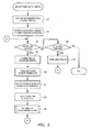
- FIG. 5 is a flowchart illustrating a procedure of an air conditioning control process in the vehicle air conditioning apparatus of the embodiment.
- control section 36 The air conditioning control process is started by control section 36, for example, when the vehicle is activated (e.g., when an ignition switch is turned on in the case of an engine vehicle, or when the key is switched on in the case of an electric vehicle).
- vehicle e.g., when an ignition switch is turned on in the case of an engine vehicle, or when the key is switched on in the case of an electric vehicle.
- control section 36 When the air conditioning control process is started, control section 36 always performs an air conditioner ECU starting process for initializing itself (step S1), and initialization processes of various sensors and actuators (electromagnetic valve, opening/closing door of HVAC 70 or the like) (step S2) and moves on to a subsequent repetitive process.
- step S1 initializing itself
- step S2 initialization processes of various sensors and actuators (electromagnetic valve, opening/closing door of HVAC 70 or the like)
- control section 36 first confirms an operation command from an outside in steps S3 and S4, executes a heating process (step S5 to S9) in the case of a heating mode command or executes a mode process (step S10) corresponding to the command in the case of another command in a cooling mode. In the case of a command for ending the air conditioning operation, control section 36 ends this air conditioning control process.
- control section 36 first acquires information from various sensors including temperature sensors 56 and 57 (step S5), and calculates a target temperature at a blowoff port of hot air in the vehicle interior (step S6).
- control section 36 calculates the number of revolutions of compressor 38 based on the target blowoff temperature and various kinds of sensor information and instructs the drive circuit of compressor 38 to drive at this number of revolutions (step S7).
- control section 36 determines the state of HVAC 70 such as the number of revolutions of blower fan F1 and the amount of opening/closing of the various opening/closing doors based on a target blowoff temperature and the various kinds of sensor information, and instructs the respective drive sections about them (step S8).
- control section 36 determines the number of revolutions of water pump (WP1) 16 based on the target blowoff temperature and the various kinds of sensor information, and instructs the drive circuit of water pump 16 to drive at this number of revolutions (step S9).
- control section 36 For a period during which a heating mode command lasts, control section 36 repeatedly executes the heating process in steps S5 to S9 and this repetitive process realizes heating operation of vehicle air conditioning apparatus 1.
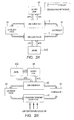
- FIG. 6 is a flowchart illustrating a detailed procedure of a process of a "WP1 number of revolutions instruction" in FIG 5 .
- FIG. 7 is a data table illustrating a relationship between an outside air temperature and a WP1 stopping water temperature.
- control section 36 first reads a stopping water temperature of water pump (WP1) 16 corresponding to the outside air temperature from the data table (step S11).
- Control section 36 stores, for example, the data table in FIG. 7 in an internal memory.
- the data table stores information indicating a relationship between an outside air temperature and a stopping water temperature.
- the water temperature is a temperature of the coolant flowing into sub-condenser 12 and the stopping water temperature indicates a threshold temperature at which water pump 16 is changed from a stopped condition to standard rotation.
- the outside air temperature does not show a range less than -20°C, but the stopping water temperature may also be set in the range less than -20°C as appropriate.
- control section 36 next compares the temperature of the coolant of sub-condenser 12 (called “condenser water temperature”) with the stopping water temperature (step S12). If the condenser water temperature is higher, the number of revolutions of water pump 16 is set to a standard number of revolutions (step S 13). The flow rate of the coolant at this time corresponds to a first flow rate. On the other hand, if the condenser water temperature is lower, the number of revolutions of water pump 16 is substantially stopped (substantially flow rate 0) (step S 14). The flow rate of the coolant at this time corresponds to an example of a second flow rate. Suppose that substantial flow rate 0 includes a case where the coolant slightly flows while no driving force is given to water pump 16 due to convection or acceleration of the vehicle or the like.
- control section 36 outputs a control signal to the drive circuit of water pump 16 so that water pump 16 is driven at the set number of revolutions (step S15).
- the process of this WP1 number of revolutions instruction ends.
- FIG. 8 is a graph for describing an example of an air conditioning control process.
- vehicle air conditioning apparatus 1 of the present embodiment the air conditioning operation as shown in FIG. 8 is obtained through the aforementioned control process.
- control section 36 determines these states through the process of compressor number of revolutions instruction (step S7 in FIG. 5 ) and warms up compressor 38 for a predetermined time period.
- the periods of "3000 rpm" and "5000 rpm” in FIG. 8 indicate warming-up of compressor 38.
- Control section 36 controls water pump 16 in a stopped condition (second flow rate) in the process of WP1 number of revolutions instruction (step S9 in FIG. 5 and FIG. 6 ) until the condenser water temperature (coolant temperature of sub-condenser 12) exceeds the stopping water temperature.
- Such control causes heat to be hardly sent from sub-condenser 12, and warming-up of the heat pump causes the temperature of the refrigerant to speedily rise, and as a result, the temperature of the devices such as compressor 38 mounted in the refrigerant cycle also speedily rises.
- the operation of the heat pump can be speedily stabilized.
- the state in which water pump 16 is being driven at the standard number of revolutions becomes the standard operation of water pump 16.
- the standard number of revolutions refers to a number of revolutions at which a heat capacity capable of heating the vehicle interior can be transported from sub-condenser 12 to heater core 44.
- vehicle air conditioning apparatus 1 of the embodiment can speedily provide heating for the vehicle interior through the above-described operation.
- Vehicle air conditioning apparatus 1 of the embodiment changes whether to operate water pump 16 with the drive amount (standard number of revolutions) during standard operation or with the drive amount lower than that during standard operation (e.g., stopped) according to the condenser water temperature.
- the condenser water temperature is high at the time of startup, for example, when vehicle air conditioning apparatus 1 is restarted after a short period from an operation end, such control can avoid an unnecessary stop period of water pump 16.
- Vehicle air conditioning apparatus 1 of the embodiment changes a threshold temperature (WP1 stopping water temperature) of the condenser water temperature at which the number of revolutions of water pump 16 is changed according to the outside air temperature.
- WP1 stopping water temperature a threshold temperature of the condenser water temperature at which the number of revolutions of water pump 16 is changed according to the outside air temperature. This can provide control suited to an outside air temperature, such as supplying warm air into the vehicle interior as early as possible even at a low temperature in the extremely cold seasons.
- FIG. 9 illustrates a variation of the vehicle air conditioning apparatus of the embodiment.
- vehicle air conditioning apparatus 1 of the above-described embodiment may be changed to vehicle air conditioning apparatus 1A in FIG. 9 .
- Vehicle air conditioning apparatus 1A in the variation only differs in the water circuit from the configuration of the embodiment shown in FIG. 4 and is the same in other configuration and control contents.
- the water circuit in FIG. 9 is a water circuit that circulates the coolant through engine cooling section 40, sub-condenser 12, heater core 44, and sub-evaporator 11, in the order mentioned, with the flow then returning to engine cooling section 40 again.
- Water pump 16A is arranged as a flow rate adjusting section at some midpoint of this water circuit.
- water pump 16 may be controlled to an amount of drive lower than that during the standard operation for a predetermined time corresponding to the outside air temperature after the startup time and similar effects are also obtained by such control.
- water pump 16 may be controlled to an amount of drive lower than that during the standard operation during warming-up of the compressor and for a predetermined time after warming-up is completed and similar effects are obtained by such control as well.
- Controlling water pump 16 to an amount of drive during the standard operation means adjusting the flow rate of the coolant to the first flow rate during the standard operation. Furthermore, controlling water pump 16 to an amount of drive lower than that during the standard operation means adjusting the flow rate of the coolant to a second flow rate lower than the first flow rate.
- Stopping (number of revolutions 0) has been illustrated as an amount of drive of water pump 16 lower than that during the standard operation, but the number of revolutions at which a heat capacity capable of providing heating for the vehicle interior cannot be transported from sub-condenser 12 to heater core 44, for example, 25% of the standard number of revolutions or below may be adopted.
- a substantially zero flow rate has been illustrated as the second flow rate of the coolant adjusted to be lower than that during the standard operation, a flow rate equal to or less than 25% of the flow rate during the standard operation may be set as the second flow rate.
- This configuration also produces a similar effect that the heat pump can be set to a stable state more speedily than driving the heat pump at the standard number of revolutions.
- the standard number of revolutions of water pump 16 may not be constant, and may be provided in two or multiple stages. That is, the standard number of revolutions may be considered as the number of revolutions at which a heat capacity capable of heating the vehicle interior can be transported from sub-condenser 12 to heater core 44.
- the flow rate of the coolant during the standard operation (first flow rate) may not be constant and may be changed in two or multiple stages. That is, the flow rate of the coolant during the standard operation may be considered as a flow rate at which a heat capacity capable of heating the vehicle interior can be transported from sub-condenser 12 to heater core 44.
- the refrigerant passes through sub-condenser 12 in the cooling mode.
- the refrigerant may be switched to a refrigerant circuit in which the refrigerant bypasses sub-condenser 12 and circulates through compressor 38, outdoor condenser 39, expansion valve 37 and evaporator 48.
- the above embodiment has described a configuration in which the amount of drive of the water pump is adjusted as an example of the flow rate adjusting section that adjusts the flow rate of the coolant.
- a valve or opening/closing door or the like arranged on the channel may be used as the flow rate adjusting section.
- the above embodiment has described an engine as an example of the heat-generating parts of the vehicle.
- various heat-generating parts may be adopted such as a driving electric motor in an electric vehicle and a secondary battery for supplying power for driving, as the heat-generating parts of the vehicle.
- compressor 38 may be a compressor which is driven by engine power. Both a fixed-capacity compressor whose discharge capacity is fixed and a variable-capacity compressor whose discharge capacity is variable may be used as the compressor driven by engine power.
- the present invention is applicable to a vehicle air conditioning apparatus to be mounted on various vehicles such as an engine vehicle, an electric automobile and an HEV.
Landscapes
- Engineering & Computer Science (AREA)
- Physics & Mathematics (AREA)
- Thermal Sciences (AREA)
- Mechanical Engineering (AREA)
- General Engineering & Computer Science (AREA)
- Air-Conditioning For Vehicles (AREA)
Applications Claiming Priority (2)
| Application Number | Priority Date | Filing Date | Title |
|---|---|---|---|
| JP2013044139 | 2013-03-06 | ||
| PCT/JP2014/001200 WO2014136447A1 (ja) | 2013-03-06 | 2014-03-05 | 車両用空調装置 |
Publications (2)
| Publication Number | Publication Date |
|---|---|
| EP2965931A1 true EP2965931A1 (de) | 2016-01-13 |
| EP2965931A4 EP2965931A4 (de) | 2016-02-24 |
Family
ID=51490980
Family Applications (1)
| Application Number | Title | Priority Date | Filing Date |
|---|---|---|---|
| EP14759689.4A Withdrawn EP2965931A4 (de) | 2013-03-06 | 2014-03-05 | Klimaanlagevorrichtung für fahrzeug |
Country Status (5)
| Country | Link |
|---|---|
| US (1) | US20160001636A1 (de) |
| EP (1) | EP2965931A4 (de) |
| JP (1) | JP6388213B2 (de) |
| CN (1) | CN105026193B (de) |
| WO (1) | WO2014136447A1 (de) |
Cited By (1)
| Publication number | Priority date | Publication date | Assignee | Title |
|---|---|---|---|---|
| US11801085B2 (en) | 2006-06-28 | 2023-10-31 | Medtronic Ireland Manufacturing Unlimited Company | Devices for thermally-induced renal neuromodulation |
Families Citing this family (14)
| Publication number | Priority date | Publication date | Assignee | Title |
|---|---|---|---|---|
| JP6317959B2 (ja) * | 2014-03-10 | 2018-04-25 | 株式会社アマダホールディングス | 冷却装置 |
| JPWO2016067567A1 (ja) * | 2014-10-31 | 2017-08-17 | パナソニックIpマネジメント株式会社 | 空調制御装置および車両用空調装置、および空調制御装置の電磁弁故障判定方法 |
| WO2016103578A1 (ja) | 2014-12-24 | 2016-06-30 | パナソニックIpマネジメント株式会社 | 車両用空調装置 |
| JP6394580B2 (ja) * | 2015-12-11 | 2018-09-26 | 株式会社デンソー | 車両の制御装置 |
| DE102018114762B4 (de) | 2017-07-10 | 2023-12-28 | Hanon Systems | Verfahren zum Betreiben einer Klimaanlage eines Kraftfahrzeuges |
| KR102382721B1 (ko) * | 2017-09-27 | 2022-04-05 | 한온시스템 주식회사 | 자동차의 통합 열관리 시스템 |
| JP2019098906A (ja) * | 2017-12-01 | 2019-06-24 | 本田技研工業株式会社 | 車両用廃熱利用装置 |
| JP7119698B2 (ja) * | 2018-07-24 | 2022-08-17 | 株式会社デンソー | 車両用空調装置 |
| KR102589025B1 (ko) * | 2018-07-25 | 2023-10-17 | 현대자동차주식회사 | 전기자동차용 공조장치 제어방법 |
| JP7349246B2 (ja) * | 2019-01-30 | 2023-09-22 | サンデン株式会社 | 車両用空気調和装置 |
| CN111520932B8 (zh) * | 2019-02-02 | 2023-07-04 | 开利公司 | 热回收增强制冷系统 |
| CN111520928B (zh) | 2019-02-02 | 2023-10-24 | 开利公司 | 增强热驱动的喷射器循环 |
| JP7329373B2 (ja) * | 2019-07-01 | 2023-08-18 | 三菱重工サーマルシステムズ株式会社 | 空気調和ユニット、熱交換器、および空気調和機 |
| CN114290868B (zh) * | 2021-04-28 | 2024-02-09 | 三电(中国)汽车空调有限公司 | 一种汽车和空调器 |
Family Cites Families (19)
| Publication number | Priority date | Publication date | Assignee | Title |
|---|---|---|---|---|
| JPS5767813U (de) * | 1980-10-14 | 1982-04-23 | ||
| JPH06143974A (ja) * | 1992-11-12 | 1994-05-24 | Zexel Corp | 空気調和装置 |
| FR2699999A1 (fr) * | 1992-12-31 | 1994-07-01 | Sedepro | Dispositif doseur et procédé de dosage. |
| JP3477868B2 (ja) | 1993-12-27 | 2003-12-10 | 株式会社デンソー | 車両用空気調和装置 |
| JPH1018845A (ja) * | 1996-07-01 | 1998-01-20 | Sanyo Electric Co Ltd | 内燃機関の冷却水流量制御装置 |
| JP4144996B2 (ja) * | 2000-04-12 | 2008-09-03 | 大阪瓦斯株式会社 | 貯湯式の給湯熱源装置 |
| JP4169454B2 (ja) * | 2000-04-12 | 2008-10-22 | 大阪瓦斯株式会社 | 貯湯式の給湯熱源装置 |
| DE10234087A1 (de) * | 2002-07-26 | 2004-02-05 | Robert Bosch Gmbh | Verfahren zum Betrieb eines Kühl- und Heizkreislaufs eines Kraftfahrzeugs sowie Kühl- und Heizkreislauf für ein Kraftfahrzeug |
| JP3801122B2 (ja) * | 2002-09-05 | 2006-07-26 | 松下電器産業株式会社 | ヒートポンプ給湯装置 |
| US6862892B1 (en) * | 2003-08-19 | 2005-03-08 | Visteon Global Technologies, Inc. | Heat pump and air conditioning system for a vehicle |
| JP2006132818A (ja) * | 2004-11-04 | 2006-05-25 | Matsushita Electric Ind Co Ltd | 冷凍サイクル装置の制御方法およびそれを用いた冷凍サイクル装置 |
| DE102007055005B4 (de) * | 2007-11-14 | 2009-08-27 | Federal-Mogul Wiesbaden Gmbh | Anlaufscheibe und Radial-Axial-Lager mit einer solchen |
| JP2010159006A (ja) * | 2009-01-09 | 2010-07-22 | Calsonic Kansei Corp | 車両用空調装置 |
| JP2010260449A (ja) * | 2009-05-07 | 2010-11-18 | Nippon Soken Inc | 車両用空調装置 |
| EP2433192B2 (de) * | 2009-05-18 | 2020-08-26 | Gentherm Incorporated | Temperaturregelungssystem mit thermoelektrischem element |
| WO2012032787A1 (ja) * | 2010-09-10 | 2012-03-15 | パナソニック株式会社 | 熱媒体循環型ヒートポンプ暖房機 |
| JP5861495B2 (ja) * | 2011-04-18 | 2016-02-16 | 株式会社デンソー | 車両用温度調整装置、および車載用熱システム |
| JP5708249B2 (ja) * | 2011-05-27 | 2015-04-30 | 株式会社ノーリツ | ヒートポンプ給湯装置 |
| JP5533812B2 (ja) * | 2011-07-28 | 2014-06-25 | 株式会社デンソー | 車両用空調装置 |
-
2014
- 2014-03-05 EP EP14759689.4A patent/EP2965931A4/de not_active Withdrawn
- 2014-03-05 US US14/770,533 patent/US20160001636A1/en not_active Abandoned
- 2014-03-05 JP JP2015504180A patent/JP6388213B2/ja not_active Expired - Fee Related
- 2014-03-05 WO PCT/JP2014/001200 patent/WO2014136447A1/ja active Application Filing
- 2014-03-05 CN CN201480012057.1A patent/CN105026193B/zh not_active Expired - Fee Related
Cited By (1)
| Publication number | Priority date | Publication date | Assignee | Title |
|---|---|---|---|---|
| US11801085B2 (en) | 2006-06-28 | 2023-10-31 | Medtronic Ireland Manufacturing Unlimited Company | Devices for thermally-induced renal neuromodulation |
Also Published As
| Publication number | Publication date |
|---|---|
| CN105026193A (zh) | 2015-11-04 |
| WO2014136447A1 (ja) | 2014-09-12 |
| EP2965931A4 (de) | 2016-02-24 |
| JP6388213B2 (ja) | 2018-09-12 |
| JPWO2014136447A1 (ja) | 2017-02-09 |
| CN105026193B (zh) | 2017-04-05 |
| US20160001636A1 (en) | 2016-01-07 |
Similar Documents
| Publication | Publication Date | Title |
|---|---|---|
| EP2965931A1 (de) | Klimaanlagevorrichtung für fahrzeug | |
| CN111791671B (zh) | 车载调温装置 | |
| JP7172815B2 (ja) | 車載温調装置 | |
| KR101715723B1 (ko) | 차량용 히트 펌프 시스템 | |
| JP6108322B2 (ja) | 車両用空調装置 | |
| CN110385965B (zh) | 车辆的热管理系统 | |
| EP2965933A1 (de) | Fahrzeugklimaanlagenvorrichtung und komponente dafür | |
| CN108136876B (zh) | 车辆用温度调整装置 | |
| JP7115452B2 (ja) | 冷却システム | |
| JP7111082B2 (ja) | 冷却システム | |
| US10350964B2 (en) | Air conditioning device for vehicle | |
| CN112606651B (zh) | 车载温度调节装置 | |
| EP3878670A1 (de) | Fahrzeugtemperaturregelsystem | |
| KR101748209B1 (ko) | 차량용 히트 펌프 시스템 | |
| JP2021014201A (ja) | 車載温調装置 | |
| JP2017128223A (ja) | 車両用冷却液加熱装置及び車両用冷却液加熱プログラム | |
| WO2017163659A1 (ja) | 車両用空調装置 | |
| JP2018111339A (ja) | 電動車両用空調装置 | |
| WO2008105304A1 (ja) | 車両の冷却システム及び車両の冷却システムの制御方法 | |
| KR20200055196A (ko) | 차량용 냉난방 시스템 | |
| WO2017163687A1 (ja) | 車両用空調装置および空調制御方法 | |
| KR20170087080A (ko) | 차량용 히트 펌프 시스템 | |
| JP2002234335A (ja) | 車両用空調装置 | |
| JP2014172431A (ja) | 車両用空調装置 |
Legal Events
| Date | Code | Title | Description |
|---|---|---|---|
| PUAI | Public reference made under article 153(3) epc to a published international application that has entered the european phase |
Free format text: ORIGINAL CODE: 0009012 |
|
| 17P | Request for examination filed |
Effective date: 20150826 |
|
| AK | Designated contracting states |
Kind code of ref document: A1 Designated state(s): AL AT BE BG CH CY CZ DE DK EE ES FI FR GB GR HR HU IE IS IT LI LT LU LV MC MK MT NL NO PL PT RO RS SE SI SK SM TR |
|
| AX | Request for extension of the european patent |
Extension state: BA ME |
|
| A4 | Supplementary search report drawn up and despatched |
Effective date: 20160127 |
|
| RIC1 | Information provided on ipc code assigned before grant |
Ipc: B60H 1/00 20060101ALI20160121BHEP Ipc: F25B 25/00 20060101ALI20160121BHEP Ipc: F25B 29/00 20060101ALI20160121BHEP Ipc: B60H 1/03 20060101AFI20160121BHEP Ipc: F25B 5/02 20060101ALI20160121BHEP Ipc: F25B 6/04 20060101ALI20160121BHEP Ipc: F25B 1/00 20060101ALI20160121BHEP Ipc: B60H 1/08 20060101ALI20160121BHEP Ipc: B60H 1/32 20060101ALI20160121BHEP |
|
| DAX | Request for extension of the european patent (deleted) | ||
| GRAP | Despatch of communication of intention to grant a patent |
Free format text: ORIGINAL CODE: EPIDOSNIGR1 |
|
| STAA | Information on the status of an ep patent application or granted ep patent |
Free format text: STATUS: GRANT OF PATENT IS INTENDED |
|
| INTG | Intention to grant announced |
Effective date: 20200512 |
|
| STAA | Information on the status of an ep patent application or granted ep patent |
Free format text: STATUS: THE APPLICATION IS DEEMED TO BE WITHDRAWN |
|
| 18D | Application deemed to be withdrawn |
Effective date: 20200923 |