EP2965028B1 - Kältegerät mit einem versetzbaren aufbewahrungsbehälter - Google Patents
Kältegerät mit einem versetzbaren aufbewahrungsbehälter Download PDFInfo
- Publication number
- EP2965028B1 EP2965028B1 EP14707777.0A EP14707777A EP2965028B1 EP 2965028 B1 EP2965028 B1 EP 2965028B1 EP 14707777 A EP14707777 A EP 14707777A EP 2965028 B1 EP2965028 B1 EP 2965028B1
- Authority
- EP
- European Patent Office
- Prior art keywords
- spacer
- pull
- refrigeration appliance
- storage compartment
- compartment
- Prior art date
- Legal status (The legal status is an assumption and is not a legal conclusion. Google has not performed a legal analysis and makes no representation as to the accuracy of the status listed.)
- Active
Links
- 238000005057 refrigeration Methods 0.000 title claims description 39
- 125000006850 spacer group Chemical group 0.000 claims description 57
- 239000003507 refrigerant Substances 0.000 description 5
- 239000012530 fluid Substances 0.000 description 4
- 235000013305 food Nutrition 0.000 description 3
- 235000013361 beverage Nutrition 0.000 description 2
- 230000000694 effects Effects 0.000 description 2
- 241000251468 Actinopterygii Species 0.000 description 1
- 230000006978 adaptation Effects 0.000 description 1
- 239000003570 air Substances 0.000 description 1
- 239000012080 ambient air Substances 0.000 description 1
- 230000006835 compression Effects 0.000 description 1
- 238000007906 compression Methods 0.000 description 1
- 239000002826 coolant Substances 0.000 description 1
- 230000001419 dependent effect Effects 0.000 description 1
- 238000011161 development Methods 0.000 description 1
- 230000018109 developmental process Effects 0.000 description 1
- 238000009434 installation Methods 0.000 description 1
- 239000007788 liquid Substances 0.000 description 1
- 238000004519 manufacturing process Methods 0.000 description 1
- 239000000463 material Substances 0.000 description 1
- 235000013372 meat Nutrition 0.000 description 1
Images


Classifications
-
- F—MECHANICAL ENGINEERING; LIGHTING; HEATING; WEAPONS; BLASTING
- F25—REFRIGERATION OR COOLING; COMBINED HEATING AND REFRIGERATION SYSTEMS; HEAT PUMP SYSTEMS; MANUFACTURE OR STORAGE OF ICE; LIQUEFACTION SOLIDIFICATION OF GASES
- F25D—REFRIGERATORS; COLD ROOMS; ICE-BOXES; COOLING OR FREEZING APPARATUS NOT OTHERWISE PROVIDED FOR
- F25D25/00—Charging, supporting, and discharging the articles to be cooled
- F25D25/02—Charging, supporting, and discharging the articles to be cooled by shelves
- F25D25/021—Charging, supporting, and discharging the articles to be cooled by shelves combined with trays
-
- F—MECHANICAL ENGINEERING; LIGHTING; HEATING; WEAPONS; BLASTING
- F25—REFRIGERATION OR COOLING; COMBINED HEATING AND REFRIGERATION SYSTEMS; HEAT PUMP SYSTEMS; MANUFACTURE OR STORAGE OF ICE; LIQUEFACTION SOLIDIFICATION OF GASES
- F25D—REFRIGERATORS; COLD ROOMS; ICE-BOXES; COOLING OR FREEZING APPARATUS NOT OTHERWISE PROVIDED FOR
- F25D25/00—Charging, supporting, and discharging the articles to be cooled
- F25D25/005—Charging, supporting, and discharging the articles to be cooled using containers
-
- F—MECHANICAL ENGINEERING; LIGHTING; HEATING; WEAPONS; BLASTING
- F25—REFRIGERATION OR COOLING; COMBINED HEATING AND REFRIGERATION SYSTEMS; HEAT PUMP SYSTEMS; MANUFACTURE OR STORAGE OF ICE; LIQUEFACTION SOLIDIFICATION OF GASES
- F25D—REFRIGERATORS; COLD ROOMS; ICE-BOXES; COOLING OR FREEZING APPARATUS NOT OTHERWISE PROVIDED FOR
- F25D25/00—Charging, supporting, and discharging the articles to be cooled
- F25D25/02—Charging, supporting, and discharging the articles to be cooled by shelves
- F25D25/024—Slidable shelves
- F25D25/025—Drawers
-
- F—MECHANICAL ENGINEERING; LIGHTING; HEATING; WEAPONS; BLASTING
- F25—REFRIGERATION OR COOLING; COMBINED HEATING AND REFRIGERATION SYSTEMS; HEAT PUMP SYSTEMS; MANUFACTURE OR STORAGE OF ICE; LIQUEFACTION SOLIDIFICATION OF GASES
- F25D—REFRIGERATORS; COLD ROOMS; ICE-BOXES; COOLING OR FREEZING APPARATUS NOT OTHERWISE PROVIDED FOR
- F25D25/00—Charging, supporting, and discharging the articles to be cooled
- F25D25/02—Charging, supporting, and discharging the articles to be cooled by shelves
Definitions
- the invention relates to a refrigeration device with a cold compartment, in which a storage container for items to be cooled is mounted so that it can be moved between an inserted position and an extended position on an extension plate.
- Refrigeration appliances in particular refrigeration appliances designed as household appliances, are known and are used for housekeeping in households or in the catering sector in order to store perishable food and / or beverages at certain temperatures.
- Such refrigeration devices have the option of changing the door hinge, i.e. depending on the standing situation or the installation situation of the refrigeration device, the opening direction of a refrigeration device door can be adjusted by moving a door hinge. It should be possible to pull out a storage container mounted on the pull-out plate with a door opening angle of at least 90 ° up to a door spar of the refrigerator door. To ensure this, a certain minimum distance must be maintained on both sides between the storage container and a collision edge of the refrigerator door. The result is unused volume of refrigerated goods in the refrigeration compartment.
- DE 10 2007 060 834 A1 discloses a refrigeration device with a cooled interior, a front door for closing the interior and a shell that can be pulled out of the interior to the front.
- a refrigeration device with a cooled interior, a front door for closing the interior and a shell that can be pulled out of the interior to the front.
- In the interior there is a horizontally arranged plate on which a removable guide base with first guide elements rests in its top surface.
- the pull-out shell has second guide elements in its bottom surface, which interact with the first guide elements.
- EP 0 498 485 A2 discloses a refrigerator with an extendable refrigerated goods carrier mounted on lateral guides in the container, and a door which, in a 90 ° open position, protrudes with parts into the pull-out area.
- a spacing gap is provided between the refrigerated goods carrier and the adjacent side wall, which allows the refrigerated goods carrier to be pulled out without hindrance in the 90 ° open position.
- the refrigerated goods carrier is on the handle side, leaving a narrow guide gap right up to the adjacent side wall out.
- the present invention is based on the knowledge that the volume of goods to be cooled can be increased if the storage container can be moved on the pull-out shelf.
- the object is achieved by a refrigeration device in which the storage container can be arranged in a first position and in a second position on the pull-out plate, the first position and the second position being different in the widthwise direction of the refrigeration device.
- a refrigeration device is understood in particular to be a household device, i.e. a refrigeration device that is used for housekeeping in households or in the catering sector, and in particular is used to store food and / or beverages at certain temperatures, such as a refrigerator, a freezer, a refrigerator - / freezer combination, a freezer or a wine cooler.
- a spacer can be arranged at a first location or at a second location on the pull-out shelf, with a spacer at the first location of the container in the first position and with a spacer at the second location of the container in the second Position is.
- the spacer is attached to the pull-out plate. This has the technical advantage that the spacer does not become noticeable when, for example, a storage container is removed from the refrigerator compartment.
- the spacer has a contact surface for the storage container. This has the technical advantage that the spacer, through the contact surface, the position of the Storage container on the pull-out plate. Thus, the spacer can be made small and takes up little space.
- the spacer is fastened to the pull-out plate by means of a latching connection. This has the technical advantage that the spacer can be attached without additional fasteners such as screws or bolts.
- the spacer has a latching hook for forming the latching connection.
- the locking hook has a locking lug.
- the latching connection is designed to be detachable without tools. This has the technical advantage that the position of the spacer can be shifted without the aid of tools.
- the latching connection can, for example, be designed in such a way that it releases automatically when a minimum force is exceeded.
- a spacer can be brought into a first state or a second state, the storage container being in the first position with a spacer in the first state and the storage container being in the second position with a spacer in the second state.
- the spacer has a first section and a second section, the first section being hingedly connected to the second section. This achieves the technical advantage that the spacer can be brought from the first state into the second state with a simple movement, namely a folding movement. Thus, the two sections do not have to be assembled and disassembled again in order to effect a change from the first to the second state and vice versa.
- first section and the second section of the spacer are connected to one another by a film hinge.
- the pull-out plate has at least two container holders arranged offset in the width direction of the refrigerator. This has the technical advantage that, by moving the storage container from the first container holder to the second container holder, an adaptation to the selected door stop can be made.
- a third container holder is provided. This has the technical advantage that a third, central position is also provided in which the storage container can be inserted symmetrically with the same distance on both sides, or alternatively a larger storage container can be used. This is especially true if the door can be opened wide by more than 90 °.
- Fig. 1 shows a refrigerator as an embodiment of a refrigerator 100 with a refrigerator door 102 on its refrigerator front.
- the refrigerator is used, for example, to cool food and comprises a refrigerant circuit with an evaporator (not shown), a compressor (not shown), a condenser (not shown) and a throttle element (not shown).
- the evaporator is designed as a heat exchanger in that, after expansion, the liquid refrigerant that absorbs heat from the medium to be cooled, i.e. air, is evaporated inside the refrigerator.
- the compressor is a mechanically driven component that sucks refrigerant vapor from the evaporator and expels it to the condenser at higher pressure.
- the condenser is designed as a heat exchanger in which, after compression, the evaporated refrigerant is liquefied by releasing heat to an external cooling medium, i.e. the ambient air.
- the throttle device is a device for the constant reduction of the pressure by reducing the cross-section.
- the refrigerant is a fluid that is used for heat transfer in the refrigeration generating system and that absorbs heat at low temperatures and low pressure of the fluid and releases heat at higher temperature and higher pressure of the fluid, usually including changes in state of the fluid.
- a refrigeration compartment 104 which in the present exemplary embodiment is designed as a refrigeration compartment, can be opened with the refrigeration device door 102.
- a pull-out plate 106 between an inserted position I and an extended position II (see FIG Fig. 1 ) displaceably arranged.
- a pull-out plate 106 is also referred to as a tray.
- two storage containers 114, 116 are arranged placed on the pull-out plate 106 on the pull-out plate 106.
- both storage containers 114, 116 are designed as storage containers for fish and / or meat at a temperature of approximately 1 ° Celsius.
- Such storage containers are also referred to as chiller boxes.
- Fig. 1 shows that the refrigerator door 102 has been pivoted through a door opening angle ⁇ of 90 ° in the present exemplary embodiment in order to open the cold compartment 104.
- the refrigerator door 102 forms a collision edge 108 for the drawer 106.
- the storage container 114 is arranged at a distance 112 from a side wall 110 which delimits the cold compartment 104 of the refrigerator 100.
- the storage container 114 was arranged in a first position A on the pull-out plate 106 in the cold compartment 104 of the refrigeration device 100.
- the pull-out plate 106 passes a collision edge 108 when it is shifted into the pulled-out position II.
- the pull-out plate 106 with attached storage containers 114, 116 can be pulled out to a door spar 118 of the refrigerator door 102 at a door opening angle ⁇ of 90 °.
- the refrigeration device 100 is designed in such a way that the refrigeration device door 102, as in FIG Fig. 1 shown, can be arranged on the right side or alternatively on the left side. It is thus possible to change the door hinge of the refrigerator door 102.
- a spacer 120 is arranged on the right-hand side of the pull-out plate 106.
- the spacer 120 is connected to the pull-out plate 106 by means of a latching connection 122 and can be dismantled without tools.
- the latching connection 122 is designed in such a way that it is released automatically when a minimum force is exceeded.
- the spacer 106 is in Fig. 1 arranged between the side wall 110 and the storage container 114 and defines so that the storage container 114 is in the first position A.
- the spacer 120 has a contact surface 124 which is in contact with the storage container 114 and ensures that the pull-out plate 106 remains in the first position A both in the pushed-in position I and in the pulled-out position II.
- the pull-out plate 106 with the storage containers 114, 116 is mounted displaceably in the first position A between the pushed-in position I and the pulled-out position II.
- the Fig. 2 and 3 show that for this purpose the spacer 120 is arranged at a first location 200 to the right of the storage container 114.
- the first position A is assigned to the first position 200.
- each storage container 114, 116 has a base 202, a front wall 204, two side walls 206 and a rear wall 208 each.
- both storage containers 114, 116 are made in one piece from plastic.
- both storage containers 114, 116 in the present exemplary embodiment have an integrally formed handle 210.
- Storage container 114 stands so as to fix the storage container 114 in the first position A.
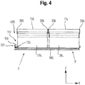
- FIG. 4 that the spacer 120 is arranged to the left of the other storage container 116.
- the spacer 120 thus defines the first position A at the first location 200 and the second position B at a second location 400, in which the storage containers 114, 116 can be displaced from the inserted position I to the extended position II and vice versa.
- the spacer 120 ensures both at the first point 200 and at the second point 400 that the storage containers 114, 116 are at a sufficient distance 112 from the collision edge 108 of the refrigerator door 102 when the refrigerator door 102 has an opening angle ⁇ 90 °.
- a change from the first position A to the second position B of the storage container 114, 116 on the pull-out plate 106 and vice versa can be effected.
- the storage containers 114, 116 on the pull-out plate 106 no longer have to have a sufficient distance from the collision edge 108 on both sides, but this space can be used on one side to increase the volume of the storage containers 114, 116, so that the overall volume of the goods to be cooled is increased.
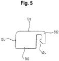
- Fig. 5 shows the spacer 120.
- the spacer 120 has a base body 500 which forms the contact surface 124.
- the spacer 120 has a latching hook 502 for forming the latching connection 122.
- the latching hook 502 is molded onto the base body 500 in the present exemplary embodiment.
- the base body 500 with the latching hook 502 is formed in one piece and of the same material.
- the latching hook 502 also has a latching lug 504 which engages in a recess in the pull-out plate 106 in order to secure the latching connection 122.
- the latching hook 502 is designed to be elastically deformable, so that when a minimum force is applied, the latching hook 502 is deformed and the latching lug 504 is disengaged.
- the spacer 120 can be detached from the pull-out plate 106 without tools and attached to a different location 200, 400 in order to effect an adjustment when the door hinge is changed.
- a spacer 120 which can optionally be arranged at a first location 200 and at a second location 400
- a spacer can also be provided which has a first and a second section which are articulated to one another, for example by means of a film hinge.
- this spacer can be brought from a first state, in which it defines the first position A for the storage containers 114, 116, into a second state, in which it defines the second position B for the storage containers 114, 116. It is thus possible to change between the first position A and the second position B by changing the state of the spacer.
- This spacer can be arranged fixedly or also releasably on the pull-out plate 106.
- Refrigeration device 400 second position 102 Refrigerator door 104 Cold compartment 500 Base body 106 Pull-out plate 502 Locking hook 108 Collision edge 504 Locking lug 110 Side wall 112 distance I. inserted position 114 Storage container II extended position 116 Storage container 118 Door pillar ⁇ Door opening angle 120 Spacers 122 Locking connection A. first position 124 Contact area B. second position X Refrigerator depth direction 200 first place Y Refrigerator width direction 202 ground Z Refrigerator vertical direction 204 Front wall 206 Side wall 208 Back wall 210 Handle
Landscapes
- Engineering & Computer Science (AREA)
- Chemical & Material Sciences (AREA)
- Combustion & Propulsion (AREA)
- Physics & Mathematics (AREA)
- Mechanical Engineering (AREA)
- Thermal Sciences (AREA)
- General Engineering & Computer Science (AREA)
- Devices That Are Associated With Refrigeration Equipment (AREA)
- Refrigerator Housings (AREA)
Priority Applications (1)
| Application Number | Priority Date | Filing Date | Title |
|---|---|---|---|
| PL14707777T PL2965028T3 (pl) | 2013-03-05 | 2014-03-04 | Urządzenie chłodzące z przestawianym pojemnikiem do przechowywania |
Applications Claiming Priority (2)
| Application Number | Priority Date | Filing Date | Title |
|---|---|---|---|
| DE102013203723.6A DE102013203723A1 (de) | 2013-03-05 | 2013-03-05 | Kältegerät mit einem versetzbaren Aufbewahrungsbehälter |
| PCT/EP2014/054126 WO2014135516A2 (de) | 2013-03-05 | 2014-03-04 | Kältegerät mit einem versetzbaren aufbewahrungsbehälter |
Publications (2)
| Publication Number | Publication Date |
|---|---|
| EP2965028A2 EP2965028A2 (de) | 2016-01-13 |
| EP2965028B1 true EP2965028B1 (de) | 2021-05-12 |
Family
ID=50193510
Family Applications (1)
| Application Number | Title | Priority Date | Filing Date |
|---|---|---|---|
| EP14707777.0A Active EP2965028B1 (de) | 2013-03-05 | 2014-03-04 | Kältegerät mit einem versetzbaren aufbewahrungsbehälter |
Country Status (6)
| Country | Link |
|---|---|
| US (1) | US9297576B2 (pl) |
| EP (1) | EP2965028B1 (pl) |
| CN (1) | CN105008831B (pl) |
| DE (1) | DE102013203723A1 (pl) |
| PL (1) | PL2965028T3 (pl) |
| WO (1) | WO2014135516A2 (pl) |
Families Citing this family (4)
| Publication number | Priority date | Publication date | Assignee | Title |
|---|---|---|---|---|
| DE102014218275A1 (de) * | 2014-09-12 | 2016-03-17 | BSH Hausgeräte GmbH | Kältegerät mit Auszugkasten |
| CN106382786B (zh) * | 2016-08-31 | 2022-05-17 | 合肥雪祺电气股份有限公司 | 90度开门冰箱抽屉安装结构及冰箱 |
| DE102017211526A1 (de) * | 2017-07-06 | 2019-01-10 | BSH Hausgeräte GmbH | Haushaltsgerätevorrichtung |
| DE102020210279A1 (de) * | 2020-08-13 | 2022-02-17 | BSH Hausgeräte GmbH | Haushaltskältegerät mit einer mit einem rollenlosen Festlager gelagerten Lebensmittel-Aufnahmeschale |
Family Cites Families (12)
| Publication number | Priority date | Publication date | Assignee | Title |
|---|---|---|---|---|
| US2064096A (en) * | 1935-06-20 | 1936-12-15 | John T Whalen | Shelf support |
| DE4103334A1 (de) | 1991-02-05 | 1992-08-06 | Bauknecht Hausgeraete | Kuehlgeraet |
| KR19980056962A (ko) * | 1996-12-30 | 1998-09-25 | 배순훈 | 다수개의 야채상자가 구비된 냉장고 |
| CN2731373Y (zh) * | 2004-09-06 | 2005-10-05 | 伊莱克斯(中国)电器有限公司 | 一种保鲜果菜盒 |
| DE102006037541B4 (de) * | 2005-08-11 | 2020-02-13 | Lg Electronics Inc. | Behälteranordnung für einen Kühlschrank |
| EP1996881B1 (en) * | 2006-03-13 | 2018-10-03 | LG Electronics, Inc. | A refrigerator comprising a cool air supply structure of a storage receptacle |
| KR100876686B1 (ko) * | 2007-04-24 | 2008-12-31 | 엘지전자 주식회사 | 냉장고의 저장용기 출입 구조 |
| DE102007060834A1 (de) * | 2007-12-18 | 2009-06-25 | BSH Bosch und Siemens Hausgeräte GmbH | Kältegerät |
| EP2371242B1 (en) * | 2008-12-31 | 2015-04-08 | Segos Co., Ltd | Sliding device |
| DE102009002061A1 (de) * | 2009-03-31 | 2010-10-14 | BSH Bosch und Siemens Hausgeräte GmbH | Haushaltskältegerät |
| DE102010043422B4 (de) * | 2010-11-04 | 2024-04-04 | Schock Metallwerk Gmbh | Befestigungsvorrichtung |
| US20120325827A1 (en) * | 2011-06-21 | 2012-12-27 | General Electric Company | Refrigerator with a slide-out pan assembly |
-
2013
- 2013-03-05 DE DE102013203723.6A patent/DE102013203723A1/de not_active Withdrawn
-
2014
- 2014-03-04 CN CN201480011689.6A patent/CN105008831B/zh active Active
- 2014-03-04 EP EP14707777.0A patent/EP2965028B1/de active Active
- 2014-03-04 WO PCT/EP2014/054126 patent/WO2014135516A2/de not_active Ceased
- 2014-03-04 PL PL14707777T patent/PL2965028T3/pl unknown
- 2014-03-04 US US14/772,860 patent/US9297576B2/en not_active Expired - Fee Related
Non-Patent Citations (1)
| Title |
|---|
| None * |
Also Published As
| Publication number | Publication date |
|---|---|
| EP2965028A2 (de) | 2016-01-13 |
| DE102013203723A1 (de) | 2014-09-11 |
| PL2965028T3 (pl) | 2022-01-03 |
| WO2014135516A3 (de) | 2014-10-30 |
| US9297576B2 (en) | 2016-03-29 |
| CN105008831B (zh) | 2017-06-13 |
| WO2014135516A2 (de) | 2014-09-12 |
| US20160054051A1 (en) | 2016-02-25 |
| CN105008831A (zh) | 2015-10-28 |
Similar Documents
| Publication | Publication Date | Title |
|---|---|---|
| EP2880387B1 (de) | Kältegerät mit einem tablett | |
| EP2932173B1 (de) | Kältegerät mit einem türabsteller | |
| EP2108907B1 (de) | Kältegerät, insbesondere Haushaltskältegerät, mit mehrteiliger Türschiene für einen Türabsteller | |
| EP2965028B1 (de) | Kältegerät mit einem versetzbaren aufbewahrungsbehälter | |
| WO2014118005A1 (de) | Kältegerät mit einem behälter | |
| EP3199896B1 (de) | Kühlschranktablar mit federelement | |
| DE102011003037A1 (de) | Kältegerät mit mehreren Verdampfern | |
| EP2932174A1 (de) | Kältegerät mit einem flaschenhalter | |
| EP2965027B1 (de) | Kältegerät mit einer versetzbaren schublade | |
| DE102009054661A1 (de) | Kältegerät mit einem Türabsteller und einer Rastvorrichtung | |
| EP2743621B1 (de) | Kältegerät mit einem Fachboden | |
| DE202004007836U1 (de) | Kühlsystem | |
| DE102011087785A1 (de) | Haushaltskältegerät mit einem Fachboden | |
| EP2898272B1 (de) | Kältegerät mit einem behälter | |
| EP3457058B1 (de) | Kältegerät mit einem fachboden | |
| EP2618084B1 (de) | Ablagevorrichtung aufweisend eine Klappenbefestigungsvorrichtung und Haushaltskältegerät mit einer solchen Ablagevorrichtung | |
| DE102017216293A1 (de) | Türabsteller für ein Kältegerät | |
| EP2743620A2 (de) | Kältegerät mit einem Fachboden | |
| DE102012221800A1 (de) | Kältegerät mit einem Kunststoffbehälter | |
| DE102016215923A1 (de) | Kältegerät mit einer bewegbaren Trennwand | |
| EP2920531B1 (de) | Kältegerät | |
| WO2014090696A1 (de) | Kältegerät mit einem kältegeräteabsteller | |
| EP2932175B1 (de) | Kältegerät mit einem flaschenhalter | |
| EP2420779A2 (de) | Lagerungseinheit und diese verwendendes Kältegerät | |
| DE102013221543A1 (de) | Kältegerät |
Legal Events
| Date | Code | Title | Description |
|---|---|---|---|
| PUAI | Public reference made under article 153(3) epc to a published international application that has entered the european phase |
Free format text: ORIGINAL CODE: 0009012 |
|
| 17P | Request for examination filed |
Effective date: 20151005 |
|
| AK | Designated contracting states |
Kind code of ref document: A2 Designated state(s): AL AT BE BG CH CY CZ DE DK EE ES FI FR GB GR HR HU IE IS IT LI LT LU LV MC MK MT NL NO PL PT RO RS SE SI SK SM TR |
|
| AX | Request for extension of the european patent |
Extension state: BA ME |
|
| RIN1 | Information on inventor provided before grant (corrected) |
Inventor name: ALT, RENE Inventor name: BECKE, CHRISTOPH Inventor name: KLEINLEIN, PHILIPP Inventor name: CELIK, CETIN Inventor name: FINK, JUERGEN Inventor name: FREYTAG-SCHOENWALDE, HOLGER Inventor name: TISCHER, THOMAS Inventor name: STAUD, RALPH Inventor name: EICHER, MAX Inventor name: HARTWEIN, CHRISTINE Inventor name: CIZIK, HERBERT |
|
| RIN1 | Information on inventor provided before grant (corrected) |
Inventor name: FINK, JUERGEN Inventor name: EICHER, MAX Inventor name: CIZIK, HERBERT Inventor name: TISCHER, THOMAS Inventor name: HARTWEIN, CHRISTINE Inventor name: ALT, RENE Inventor name: FREYTAG-SCHOENWALDE, HOLGER Inventor name: CELIK, CETIN Inventor name: STAUD, RALPH Inventor name: BECKE, CHRISTOPH Inventor name: KLEINLEIN, PHILIPP |
|
| DAX | Request for extension of the european patent (deleted) | ||
| 17Q | First examination report despatched |
Effective date: 20161011 |
|
| STAA | Information on the status of an ep patent application or granted ep patent |
Free format text: STATUS: EXAMINATION IS IN PROGRESS |
|
| GRAP | Despatch of communication of intention to grant a patent |
Free format text: ORIGINAL CODE: EPIDOSNIGR1 |
|
| STAA | Information on the status of an ep patent application or granted ep patent |
Free format text: STATUS: GRANT OF PATENT IS INTENDED |
|
| INTG | Intention to grant announced |
Effective date: 20201028 |
|
| GRAS | Grant fee paid |
Free format text: ORIGINAL CODE: EPIDOSNIGR3 |
|
| GRAA | (expected) grant |
Free format text: ORIGINAL CODE: 0009210 |
|
| STAA | Information on the status of an ep patent application or granted ep patent |
Free format text: STATUS: THE PATENT HAS BEEN GRANTED |
|
| AK | Designated contracting states |
Kind code of ref document: B1 Designated state(s): AL AT BE BG CH CY CZ DE DK EE ES FI FR GB GR HR HU IE IS IT LI LT LU LV MC MK MT NL NO PL PT RO RS SE SI SK SM TR |
|
| REG | Reference to a national code |
Ref country code: GB Ref legal event code: FG4D Free format text: NOT ENGLISH |
|
| REG | Reference to a national code |
Ref country code: CH Ref legal event code: EP |
|
| REG | Reference to a national code |
Ref country code: DE Ref legal event code: R096 Ref document number: 502014015570 Country of ref document: DE |
|
| REG | Reference to a national code |
Ref country code: IE Ref legal event code: FG4D Free format text: LANGUAGE OF EP DOCUMENT: GERMAN |
|
| REG | Reference to a national code |
Ref country code: AT Ref legal event code: REF Ref document number: 1392448 Country of ref document: AT Kind code of ref document: T Effective date: 20210615 |
|
| REG | Reference to a national code |
Ref country code: LT Ref legal event code: MG9D |
|
| REG | Reference to a national code |
Ref country code: NL Ref legal event code: MP Effective date: 20210512 |
|
| PG25 | Lapsed in a contracting state [announced via postgrant information from national office to epo] |
Ref country code: HR Free format text: LAPSE BECAUSE OF FAILURE TO SUBMIT A TRANSLATION OF THE DESCRIPTION OR TO PAY THE FEE WITHIN THE PRESCRIBED TIME-LIMIT Effective date: 20210512 Ref country code: BG Free format text: LAPSE BECAUSE OF FAILURE TO SUBMIT A TRANSLATION OF THE DESCRIPTION OR TO PAY THE FEE WITHIN THE PRESCRIBED TIME-LIMIT Effective date: 20210812 Ref country code: FI Free format text: LAPSE BECAUSE OF FAILURE TO SUBMIT A TRANSLATION OF THE DESCRIPTION OR TO PAY THE FEE WITHIN THE PRESCRIBED TIME-LIMIT Effective date: 20210512 Ref country code: LT Free format text: LAPSE BECAUSE OF FAILURE TO SUBMIT A TRANSLATION OF THE DESCRIPTION OR TO PAY THE FEE WITHIN THE PRESCRIBED TIME-LIMIT Effective date: 20210512 |
|
| PG25 | Lapsed in a contracting state [announced via postgrant information from national office to epo] |
Ref country code: GR Free format text: LAPSE BECAUSE OF FAILURE TO SUBMIT A TRANSLATION OF THE DESCRIPTION OR TO PAY THE FEE WITHIN THE PRESCRIBED TIME-LIMIT Effective date: 20210813 Ref country code: LV Free format text: LAPSE BECAUSE OF FAILURE TO SUBMIT A TRANSLATION OF THE DESCRIPTION OR TO PAY THE FEE WITHIN THE PRESCRIBED TIME-LIMIT Effective date: 20210512 Ref country code: IS Free format text: LAPSE BECAUSE OF FAILURE TO SUBMIT A TRANSLATION OF THE DESCRIPTION OR TO PAY THE FEE WITHIN THE PRESCRIBED TIME-LIMIT Effective date: 20210912 Ref country code: NO Free format text: LAPSE BECAUSE OF FAILURE TO SUBMIT A TRANSLATION OF THE DESCRIPTION OR TO PAY THE FEE WITHIN THE PRESCRIBED TIME-LIMIT Effective date: 20210812 Ref country code: PT Free format text: LAPSE BECAUSE OF FAILURE TO SUBMIT A TRANSLATION OF THE DESCRIPTION OR TO PAY THE FEE WITHIN THE PRESCRIBED TIME-LIMIT Effective date: 20210913 Ref country code: ES Free format text: LAPSE BECAUSE OF FAILURE TO SUBMIT A TRANSLATION OF THE DESCRIPTION OR TO PAY THE FEE WITHIN THE PRESCRIBED TIME-LIMIT Effective date: 20210512 Ref country code: RS Free format text: LAPSE BECAUSE OF FAILURE TO SUBMIT A TRANSLATION OF THE DESCRIPTION OR TO PAY THE FEE WITHIN THE PRESCRIBED TIME-LIMIT Effective date: 20210512 Ref country code: SE Free format text: LAPSE BECAUSE OF FAILURE TO SUBMIT A TRANSLATION OF THE DESCRIPTION OR TO PAY THE FEE WITHIN THE PRESCRIBED TIME-LIMIT Effective date: 20210512 |
|
| PG25 | Lapsed in a contracting state [announced via postgrant information from national office to epo] |
Ref country code: NL Free format text: LAPSE BECAUSE OF FAILURE TO SUBMIT A TRANSLATION OF THE DESCRIPTION OR TO PAY THE FEE WITHIN THE PRESCRIBED TIME-LIMIT Effective date: 20210512 |
|
| PG25 | Lapsed in a contracting state [announced via postgrant information from national office to epo] |
Ref country code: RO Free format text: LAPSE BECAUSE OF FAILURE TO SUBMIT A TRANSLATION OF THE DESCRIPTION OR TO PAY THE FEE WITHIN THE PRESCRIBED TIME-LIMIT Effective date: 20210512 Ref country code: EE Free format text: LAPSE BECAUSE OF FAILURE TO SUBMIT A TRANSLATION OF THE DESCRIPTION OR TO PAY THE FEE WITHIN THE PRESCRIBED TIME-LIMIT Effective date: 20210512 Ref country code: CZ Free format text: LAPSE BECAUSE OF FAILURE TO SUBMIT A TRANSLATION OF THE DESCRIPTION OR TO PAY THE FEE WITHIN THE PRESCRIBED TIME-LIMIT Effective date: 20210512 Ref country code: DK Free format text: LAPSE BECAUSE OF FAILURE TO SUBMIT A TRANSLATION OF THE DESCRIPTION OR TO PAY THE FEE WITHIN THE PRESCRIBED TIME-LIMIT Effective date: 20210512 Ref country code: SK Free format text: LAPSE BECAUSE OF FAILURE TO SUBMIT A TRANSLATION OF THE DESCRIPTION OR TO PAY THE FEE WITHIN THE PRESCRIBED TIME-LIMIT Effective date: 20210512 Ref country code: SM Free format text: LAPSE BECAUSE OF FAILURE TO SUBMIT A TRANSLATION OF THE DESCRIPTION OR TO PAY THE FEE WITHIN THE PRESCRIBED TIME-LIMIT Effective date: 20210512 |
|
| REG | Reference to a national code |
Ref country code: DE Ref legal event code: R097 Ref document number: 502014015570 Country of ref document: DE |
|
| PLBE | No opposition filed within time limit |
Free format text: ORIGINAL CODE: 0009261 |
|
| STAA | Information on the status of an ep patent application or granted ep patent |
Free format text: STATUS: NO OPPOSITION FILED WITHIN TIME LIMIT |
|
| 26N | No opposition filed |
Effective date: 20220215 |
|
| PG25 | Lapsed in a contracting state [announced via postgrant information from national office to epo] |
Ref country code: IS Free format text: LAPSE BECAUSE OF FAILURE TO SUBMIT A TRANSLATION OF THE DESCRIPTION OR TO PAY THE FEE WITHIN THE PRESCRIBED TIME-LIMIT Effective date: 20210912 Ref country code: AL Free format text: LAPSE BECAUSE OF FAILURE TO SUBMIT A TRANSLATION OF THE DESCRIPTION OR TO PAY THE FEE WITHIN THE PRESCRIBED TIME-LIMIT Effective date: 20210512 |
|
| PG25 | Lapsed in a contracting state [announced via postgrant information from national office to epo] |
Ref country code: MC Free format text: LAPSE BECAUSE OF FAILURE TO SUBMIT A TRANSLATION OF THE DESCRIPTION OR TO PAY THE FEE WITHIN THE PRESCRIBED TIME-LIMIT Effective date: 20210512 |
|
| REG | Reference to a national code |
Ref country code: CH Ref legal event code: PL |
|
| GBPC | Gb: european patent ceased through non-payment of renewal fee |
Effective date: 20220304 |
|
| REG | Reference to a national code |
Ref country code: BE Ref legal event code: MM Effective date: 20220331 |
|
| PG25 | Lapsed in a contracting state [announced via postgrant information from national office to epo] |
Ref country code: LU Free format text: LAPSE BECAUSE OF NON-PAYMENT OF DUE FEES Effective date: 20220304 Ref country code: LI Free format text: LAPSE BECAUSE OF NON-PAYMENT OF DUE FEES Effective date: 20220331 Ref country code: IE Free format text: LAPSE BECAUSE OF NON-PAYMENT OF DUE FEES Effective date: 20220304 Ref country code: GB Free format text: LAPSE BECAUSE OF NON-PAYMENT OF DUE FEES Effective date: 20220304 Ref country code: FR Free format text: LAPSE BECAUSE OF NON-PAYMENT OF DUE FEES Effective date: 20220331 Ref country code: CH Free format text: LAPSE BECAUSE OF NON-PAYMENT OF DUE FEES Effective date: 20220331 |
|
| PG25 | Lapsed in a contracting state [announced via postgrant information from national office to epo] |
Ref country code: BE Free format text: LAPSE BECAUSE OF NON-PAYMENT OF DUE FEES Effective date: 20220331 |
|
| REG | Reference to a national code |
Ref country code: AT Ref legal event code: MM01 Ref document number: 1392448 Country of ref document: AT Kind code of ref document: T Effective date: 20220304 |
|
| PG25 | Lapsed in a contracting state [announced via postgrant information from national office to epo] |
Ref country code: AT Free format text: LAPSE BECAUSE OF NON-PAYMENT OF DUE FEES Effective date: 20220304 |
|
| PGFP | Annual fee paid to national office [announced via postgrant information from national office to epo] |
Ref country code: IT Payment date: 20230331 Year of fee payment: 10 |
|
| PG25 | Lapsed in a contracting state [announced via postgrant information from national office to epo] |
Ref country code: HU Free format text: LAPSE BECAUSE OF FAILURE TO SUBMIT A TRANSLATION OF THE DESCRIPTION OR TO PAY THE FEE WITHIN THE PRESCRIBED TIME-LIMIT; INVALID AB INITIO Effective date: 20140304 |
|
| PG25 | Lapsed in a contracting state [announced via postgrant information from national office to epo] |
Ref country code: MK Free format text: LAPSE BECAUSE OF FAILURE TO SUBMIT A TRANSLATION OF THE DESCRIPTION OR TO PAY THE FEE WITHIN THE PRESCRIBED TIME-LIMIT Effective date: 20210512 Ref country code: CY Free format text: LAPSE BECAUSE OF FAILURE TO SUBMIT A TRANSLATION OF THE DESCRIPTION OR TO PAY THE FEE WITHIN THE PRESCRIBED TIME-LIMIT Effective date: 20210512 |
|
| PG25 | Lapsed in a contracting state [announced via postgrant information from national office to epo] |
Ref country code: MT Free format text: LAPSE BECAUSE OF FAILURE TO SUBMIT A TRANSLATION OF THE DESCRIPTION OR TO PAY THE FEE WITHIN THE PRESCRIBED TIME-LIMIT Effective date: 20210512 |
|
| PGFP | Annual fee paid to national office [announced via postgrant information from national office to epo] |
Ref country code: DE Payment date: 20250331 Year of fee payment: 12 |
|
| PGFP | Annual fee paid to national office [announced via postgrant information from national office to epo] |
Ref country code: PL Payment date: 20250224 Year of fee payment: 12 |
|
| PG25 | Lapsed in a contracting state [announced via postgrant information from national office to epo] |
Ref country code: IT Free format text: LAPSE BECAUSE OF NON-PAYMENT OF DUE FEES Effective date: 20240304 |
|
| PGFP | Annual fee paid to national office [announced via postgrant information from national office to epo] |
Ref country code: TR Payment date: 20250224 Year of fee payment: 12 |