EP2964123B1 - Hybrid manual and robotic interventional instruments - Google Patents
Hybrid manual and robotic interventional instruments Download PDFInfo
- Publication number
- EP2964123B1 EP2964123B1 EP14760153.8A EP14760153A EP2964123B1 EP 2964123 B1 EP2964123 B1 EP 2964123B1 EP 14760153 A EP14760153 A EP 14760153A EP 2964123 B1 EP2964123 B1 EP 2964123B1
- Authority
- EP
- European Patent Office
- Prior art keywords
- drive
- coupled
- instrument
- inputs
- distal end
- Prior art date
- Legal status (The legal status is an assumption and is not a legal conclusion. Google has not performed a legal analysis and makes no representation as to the accuracy of the status listed.)
- Active
Links
Images


Classifications
-
- A—HUMAN NECESSITIES
- A61—MEDICAL OR VETERINARY SCIENCE; HYGIENE
- A61B—DIAGNOSIS; SURGERY; IDENTIFICATION
- A61B34/00—Computer-aided surgery; Manipulators or robots specially adapted for use in surgery
- A61B34/30—Surgical robots
-
- A—HUMAN NECESSITIES
- A61—MEDICAL OR VETERINARY SCIENCE; HYGIENE
- A61B—DIAGNOSIS; SURGERY; IDENTIFICATION
- A61B17/00—Surgical instruments, devices or methods
- A61B17/28—Surgical forceps
- A61B17/29—Forceps for use in minimally invasive surgery
- A61B17/2909—Handles
-
- A—HUMAN NECESSITIES
- A61—MEDICAL OR VETERINARY SCIENCE; HYGIENE
- A61B—DIAGNOSIS; SURGERY; IDENTIFICATION
- A61B34/00—Computer-aided surgery; Manipulators or robots specially adapted for use in surgery
- A61B34/70—Manipulators specially adapted for use in surgery
- A61B34/71—Manipulators operated by drive cable mechanisms
-
- A—HUMAN NECESSITIES
- A61—MEDICAL OR VETERINARY SCIENCE; HYGIENE
- A61B—DIAGNOSIS; SURGERY; IDENTIFICATION
- A61B34/00—Computer-aided surgery; Manipulators or robots specially adapted for use in surgery
- A61B34/70—Manipulators specially adapted for use in surgery
- A61B34/74—Manipulators with manual electric input means
-
- A—HUMAN NECESSITIES
- A61—MEDICAL OR VETERINARY SCIENCE; HYGIENE
- A61B—DIAGNOSIS; SURGERY; IDENTIFICATION
- A61B34/00—Computer-aided surgery; Manipulators or robots specially adapted for use in surgery
- A61B34/70—Manipulators specially adapted for use in surgery
- A61B34/76—Manipulators having means for providing feel, e.g. force or tactile feedback
-
- A—HUMAN NECESSITIES
- A61—MEDICAL OR VETERINARY SCIENCE; HYGIENE
- A61B—DIAGNOSIS; SURGERY; IDENTIFICATION
- A61B17/00—Surgical instruments, devices or methods
- A61B17/00234—Surgical instruments, devices or methods for minimally invasive surgery
- A61B2017/00292—Surgical instruments, devices or methods for minimally invasive surgery mounted on or guided by flexible, e.g. catheter-like, means
- A61B2017/003—Steerable
- A61B2017/00318—Steering mechanisms
- A61B2017/00323—Cables or rods
-
- A—HUMAN NECESSITIES
- A61—MEDICAL OR VETERINARY SCIENCE; HYGIENE
- A61B—DIAGNOSIS; SURGERY; IDENTIFICATION
- A61B17/00—Surgical instruments, devices or methods
- A61B2017/00477—Coupling
-
- A—HUMAN NECESSITIES
- A61—MEDICAL OR VETERINARY SCIENCE; HYGIENE
- A61B—DIAGNOSIS; SURGERY; IDENTIFICATION
- A61B17/00—Surgical instruments, devices or methods
- A61B17/28—Surgical forceps
- A61B17/29—Forceps for use in minimally invasive surgery
- A61B17/2909—Handles
- A61B2017/2912—Handles transmission of forces to actuating rod or piston
- A61B2017/2923—Toothed members, e.g. rack and pinion
-
- A—HUMAN NECESSITIES
- A61—MEDICAL OR VETERINARY SCIENCE; HYGIENE
- A61B—DIAGNOSIS; SURGERY; IDENTIFICATION
- A61B34/00—Computer-aided surgery; Manipulators or robots specially adapted for use in surgery
- A61B34/30—Surgical robots
- A61B2034/301—Surgical robots for introducing or steering flexible instruments inserted into the body, e.g. catheters or endoscopes
-
- A—HUMAN NECESSITIES
- A61—MEDICAL OR VETERINARY SCIENCE; HYGIENE
- A61B—DIAGNOSIS; SURGERY; IDENTIFICATION
- A61B34/00—Computer-aided surgery; Manipulators or robots specially adapted for use in surgery
- A61B34/70—Manipulators specially adapted for use in surgery
- A61B34/71—Manipulators operated by drive cable mechanisms
- A61B2034/715—Cable tensioning mechanisms for removing slack
Definitions
- the present disclosure is directed to systems for navigating a patient anatomy to conduct a minimally invasive procedure, and more particularly to systems using a hybrid manual and robotic endoscopic instrument to conduct a minimally invasive procedure.
- Minimally invasive medical techniques are intended to reduce the amount of tissue that is damaged during interventional procedures, thereby reducing patient recovery time, discomfort, and deleterious side effects.
- Such minimally invasive techniques may be performed through natural orifices in a patient anatomy or through one or more surgical incisions. Through these natural orifices or incisions clinicians may insert interventional instruments (including surgical, diagnostic, therapeutic, or biopsy instruments) to reach a target tissue location.
- interventional instruments including surgical, diagnostic, therapeutic, or biopsy instruments
- a minimally invasive interventional instrument may navigate natural or surgically created passageways in anatomical systems such as the lungs, the colon, the intestines, the kidneys, the heart, the circulatory system, or the like.
- Current interventional instruments are either manually controlled or robotically controlled.
- a clinician controls the insertion of the interventional instrument and the manipulation of the distal end of the interventional instrument in one or more degrees of freedom.
- Manually controlled systems rely primarily upon the clinician to navigate a complex network of anatomical passageways to reach a procedure location.
- Robotically controlled interventional instruments allow a remote user to use advanced imaging and navigation techniques to robotically control the interventional instrument.
- the insertion of the instrument and/ or movement of the distal end of the surgical instrument in one or more of degrees of freedom may be operated with robotic control.
- clinicians may prefer a hybrid approach, in which a single interventional instrument may be operated with manual control for a portion of the procedure and with robotic control for other portions of the procedure. Improved systems and methods are needed for providing manual and robotic control to a common interventional instrument.
- KR 2011 0003229 A discloses a hybrid surgical operation robot system and a control method thereof, in which a handle is provided to enable a user to manipulate the robot. More particularly, an instrument is connected to a robot arm, and the instrument includes the handle.
- WO 2010/127162 A1 discloses an instrument having a flexible elongate body, the instrument including a lumen, a flex member disposed within the lumen, and a pull wire disposed within the flex member.
- the flex member is configured to provide steering control to a first portion of the elongate body while providing load bearing support to a second portion of the elongate body.
- a distal portion of the pull wire is coupled to the elongate body and a proximal portion of the pull wire is operatively coupled to a control unit, and the control unit is coupled to a proximal portion of the elongate body.
- a system comprises a handpiece body configured to couple to a proximal end of a medical instrument and a manual actuator mounted in the handpiece body.
- the system further includes a plurality of drive inputs mounted in the handpiece body.
- the drive inputs are configured for engagement with a motorized drive mechanism.
- a first drive component is operably coupled to the manual actuator and operably coupled to one of the plurality of drive inputs.
- the first drive component controls movement of a distal end of the medical instrument in a first direction of a first degree of freedom.
- a second drive component is operably coupled to the manual actuator and operably coupled to another one of the plurality of drive inputs.
- the second drive component controls movement of the distal end of the medical instrument in a second direction of the first degree of freedom, the second direction being opposite to the first direction.
- a tensioning system is coupled to the handpiece body and to the plurality of drive inputs, wherein the tensioning system is configured to maintain tension in the first and second drive components.
- the plurality of drive inputs may be configured for removable engagement with the motorized drive mechanism.
- the motorized drive mechanism is mounted in the handpiece body.
- position refers to the location of an object or a portion of an object in a three-dimensional space (e.g., three degrees of translational freedom along Cartesian X, Y, Z coordinates).
- orientation refers to the rotational placement of an object or a portion of an object (three degrees of rotational freedom - e.g., roll, pitch, and yaw).
- the term “pose” refers to the position of an object or a portion of an object in at least one degree of translational freedom and to the orientation of that object or portion of the object in at least one degree of rotational freedom (up to six total degrees of freedom).
- the term “shape” refers to a set of poses, positions, or orientations measured along an elongated object.
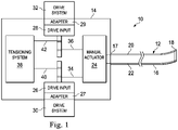
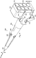
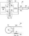
- a hybrid minimally invasive interventional instrument system 10 utilizes aspects of the present disclosure.
- the system 10 includes a medical instrument such as a catheter system 12 coupled to an instrument handpiece 14.
- the catheter system 12 includes an elongated flexible body 16 having a proximal end 17 and a distal end 18.
- the flexible body 16 has an approximately 3 mm outer diameter. Other flexible body outer diameters may be larger or smaller.
- other types of medical instruments may be coupled to and actuated by the instrument handpiece.
- the flexible body 16 houses opposing drive components 20, 22 for moving the distal end 18 of the flexible body in opposite directions.
- the drive components may control opposing pitch movements or opposing yaw movements of the distal end 18.
- additional sets of opposing drive components may be included to control multiple opposing directions of motion (e.g., pitch, yaw, and roll).
- the drive components may include tendons, linkages, or other steering controls (not shown) that extend from the instrument handpiece 14 to the distal end 18.
- Tendons are generally continuous elongated members that can withstand tension.
- Tendons may include multicomponent members such as helical wound or braided cables, ropes, loose fiber rovings, and fiber or wire reinforced belts.
- Tendons also include single component members such as wires, rods, tubes, bands, filaments or other continuous members suitable for use in tension.
- the flexible body 16 may further house control mechanisms (not shown) for operating a surgical end effector or another working distal part that is manipulable for a medical function, e.g., for effecting a predetermined treatment of a target tissue.
- a surgical end effector or another working distal part that is manipulable for a medical function, e.g., for effecting a predetermined treatment of a target tissue.
- some end effectors have a single working member such as a scalpel, a blade, a needle, an optical fiber, or an electrode.
- Other end effectors may include a pair or plurality of working members such as forceps, graspers, scissors, biopsy device, or clip appliers, for example. Examples of electrically activated end effectors include electrosurgical electrodes, transducers, sensors, and the like.
- the flexible body 16 can define one or more lumens through which interventional tools can be deployed and used at a target surgical location.
- interventional tools may include one or more cameras, biopsy devices, laser ablation fibers, medicinal delivery systems, or position and orientation sensors.
- the instrument handpiece 14 includes a manual actuator 24 such as a lever or dial movable by a user (e.g., by the user's hand or thumb) to manually control the movement of the opposing drive components 20, 22.
- the instrument handpiece 14 includes a drive input 26 movable by a drive system 30 to control the movement of the drive component 22 and a drive input 28 movable by a drive system 32 to control the movement of the drive component 20.
- the drive systems 30, 32 may be motorized components of a robotic interventional system.
- a sterile adaptor disk 27 attached to a sterile drape may be coupled to a drive input (e.g., drive input 26).
- an optional sterile adaptor disk 29 attached to a sterile drape may be coupled to a drive input (e.g., drive input 28).
- the sterile adaptor disk 27 imparts the motion from the drive system 30 to the drive input 26 while maintaining a sterile barrier between the sterile instrument components and non-sterile robotic components.
- the optional adaptor disks may be non-sterile, serving to accommodate small mis-alignments between individual motor outputs and instrument inputs.
- removable engagement of drive inputs with drive mechanisms includes direct engagement and indirect engagement via adaptor disks.
- the drive input 26 may be coupled to the manual actuator 24 by a drive component 34.
- Drive component 34 may a part of the drive component 22 (i.e., the length of the drive component 22 between the drive input and the manual actuator). Alternatively, drive components 22 and 34 may be separately connected to the manual actuator 24.
- the drive input 28 may be coupled to the manual actuator 24 by a drive component 36.
- Drive component 36 may a part of the drive component 20 (i.e., the length of the drive component 20 between the drive input and the manual actuator). Alternatively, drive components 20 and 36 may be separately connected to the manual actuator 24.
- the instrument handpiece 14 further includes a tensioning system 38 which prevents the opposing drive components 20, 22 from becoming slack and decoupling from the drive inputs or manual actuator.
- the drive input 26 may be coupled to the tensioning system 38 by a drive component 40.
- Drive component 40 may a part of the drive component 22 (i.e., the length of the drive component 22 between the drive input and the tensioning system). Alternatively, drive components 40 and 34 may be separately connected to the drive input 26.
- the drive input 28 may be coupled to the tensioning system 38 by a drive component 42.
- Drive component 42 may be a part of the drive component 20 (i.e., the length of the drive component 20 between the drive input and the tensioning system). Alternatively, drive components 42 and 36 may be separately connected to the drive input 28.
- the instrument handpiece 14 may be a component of a hybrid manual and robotic interventional system.
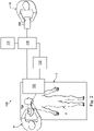
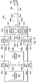
- FIG. 2 illustrates such a system 100.
- the system 100 may be used for, for example, in surgical, diagnostic, therapeutic, or biopsy procedures.
- the robotic system 100 generally includes an interventional manipulator assembly 102 (e.g., a robotic arm linkage) for operating a hybrid interventional instrument 104 (e.g., the hybrid instrument system 10) in performing various procedures on the patient P.
- the interventional instrument 104 is decoupled from the interventional manipulator 102 for use in manual mode by a surgeon S1.
- the interventional instrument would be coupled to the interventional manipulator 102.
- the manipulator assembly 102 is mounted to or near an operating table O.
- An operator input system 106 allows a surgeon S2 to view the surgical site and to control the operation of the interventional manipulator assembly 102. In some circumstances, the same person may operate the manual instrument and operate the operator input.
- the operator input system 106 may be located at a surgeon's console which is usually located in the same room as operating table O. However, it should be understood that the surgeon S2 can be located in a different room or a completely different building from the patient P.
- Operator input system 106 generally includes one or more control device(s) for controlling the manipulator assembly 102.
- the control device(s) may include any number of a variety of input devices, such as hand grips, joysticks, trackballs, data gloves, trigger-guns, hand-operated controllers, voice recognition devices, touch screens, body motion or presence sensors, or the like.
- control device(s) will be provided with the same degrees of freedom as the associated interventional instruments 104 to provide the surgeon with telepresence, or the perception that the control device(s) are integral with the instruments 104 so that the surgeon has a strong sense of directly controlling instruments 104.
- the control device(s) may have more or fewer degrees of freedom than the associated interventional instruments 104 and still provide the surgeon with telepresence.
- the control device(s) are manual input devices which move with six degrees of freedom, and which may also include an actuatable handle for actuating instruments (for example, for closing grasping jaws, applying an electrical potential to an electrode, delivering a medicinal treatment, or the like).
- the robotic system may include more than one manipulator assembly and/or more than one operator input system.
- the exact number of manipulator assemblies will depend on the surgical procedure and the space constraints within the operating room, among other factors.
- the operator input systems may be collocated, or they may be positioned in separate locations. Multiple operator input systems allow more than one operator to control one or more manipulator assemblies in various combinations.
- An optional sensor system 110 includes one or more sub-systems for receiving information about the instrument 104.
- Such sub-systems may include a position sensor system (e.g., an electromagnetic (EM) sensor system); a shape sensor system for determining the position, orientation, speed, pose, and/or shape of the catheter tip at (e.g., distal end 18 in FIG. 1 ) and/or of one or more segments along a flexible body of instrument 104; and/or a visualization system for capturing images from the distal end of the catheter system.
- the position sensor system, the shape sensor system, and/or the visualization system may interface with a tracking system of the robotic interventional system.
- the tracking system may be implemented as hardware, firmware, software or a combination thereof which interact with or are otherwise executed by one or more computer processors, which may include the processors of a control system 116, described in greater detail below.
- the optional position sensor system may be an EM sensor system that includes one or more conductive coils that may be subjected to an externally generated electromagnetic field. Each coil of the EM sensor system then produces an induced electrical signal having characteristics that depend on the position and orientation of the coil relative to the externally generated electromagnetic field.
- the EM sensor system may be configured and positioned to measure six degrees of freedom, e.g., three position coordinates X, Y, Z and three orientation angles indicating pitch, yaw, and roll of a base point. Further description of an EM sensor system is provided in U.S. Pat. No. 6,380,732, filed August 11, 1999 , disclosing "Six-Degree of Freedom Tracking System Having a Passive Transponder on the Object Being Tracked".
- the optional shape sensor system includes an optical fiber aligned with the flexible body of the instrument (e.g., provided within an interior channel (not shown) or mounted externally).
- the optical fiber has a diameter of approximately 200 ⁇ m. In other embodiments, the dimensions may be larger or smaller.
- the optical fiber of the shape sensor system forms a fiber optic bend sensor for determining the shape of the catheter system of instrument 104.
- optical fibers including Fiber Bragg Gratings (FBGs) are used to provide strain measurements in structures in one or more dimensions.
- FBGs Fiber Bragg Gratings
- Various systems and methods for monitoring the shape and relative position of an optical fiber in three dimensions are described in U.S. Pat. App. No. 11/180,389, filed July, 13, 2005 and published as US 2006-0013523 A1 , disclosing "Fiber optic position and shape sensing device and method relating thereto;" 2. unpublished U.S. Provisional Pat. App. No. 60/588,336, filed on Jul. 16, 2004 , disclosing "Fiber-optic shape and relative position sensing;" and U.S.
- the optical fiber may include multiple cores within a single cladding.
- Each core may be single-mode with sufficient distance and cladding separating the cores such that the light in each core does not interact significantly with the light carried in other cores.
- the number of cores may vary or each core may be contained in a separate optical fiber.
- an array of FBG's is provided within each core.
- Each FBG comprises a series of modulations of the core's refractive index so as to generate a spatial periodicity in the refraction index. The spacing may be chosen so that the partial reflections from each index change add coherently for a narrow band of wavelengths, and therefore reflect only this narrow band of wavelengths while passing through a much broader band.
- the modulations are spaced by a known distance, thereby causing reflection of a known band of wavelengths.
- the spacing of the modulations will change, depending on the amount of strain in the core.
- backscatter or other optical phenomena that vary with bending of the optical fiber can be used to determine strain within each core.
- FBG's produce a reflected wavelength that is a function of the strain on the fiber and its temperature.
- This FBG technology is commercially available from a variety of sources, such as Smart Fibres Ltd. of Bracknell, England. Use of FBG technology in position sensors for robotic surgery is described in U.S. Pat. No. 7,930,065, filed July 20, 2006 , disclosing "Robotic Surgery System Including Position Sensors Using Fiber Bragg Gratings".
- bending of the optical fiber When applied to a multicore fiber, bending of the optical fiber induces strain on the cores that can be measured by monitoring the wavelength shifts in each core.
- bending of the fiber induces different strains on each of the cores. These strains are a function of the local degree of bending of the fiber. For example, regions of the cores containing FBG's, if located at points where the fiber is bent, can thereby be used to determine the amount of bending at those points.
- These data combined with the known spacings of the FBG regions, can be used to reconstruct the shape of the fiber.
- Such a system has been described by Luna Innovations. Inc. of Blacksburg, Va.
- the sensing may be limited only to the degrees of freedom that are actuated by the robotic system, or may be applied to both passive (e.g., unactuated bending of the rigid members between joints) and active (e.g., actuated movement of the instrument) degrees of freedom.
- the visualization sub-system of sensor system 110 may include an image capture probe extending through the instrument catheter (not shown) for providing concurrent (realtime) image of the surgical site to surgeon.
- the image capture probe may include a tip portion with a stereoscopic or monoscopic camera disposed near, for example, the distal end 18 of the flexible body 16 of FIG. 1 for capturing images (including video images) that are transmitted to and processed by the robotic interventional system for display.
- the image capture probe may include a cable coupled to the camera for transmitting the captured image data.
- the image capture instrument may be a fiber-optic bundle, such as a fiberscope, that couples to the imaging system.
- the image capture instrument may be single or multi-spectral, for example capturing image data in the visible spectrum, or capturing image data in the visible and infrared or ultraviolet spectrums.
- the captured image may be, for example, a two- or three-dimensional image captured by an endoscopic probe positioned within the surgical site.
- the visualization sub-system includes endoscopic components that may be integrally or removably coupled to the interventional instrument 104.
- a separate endoscope attached to a separate manipulator assembly may be used to image the surgical site.
- a separate endoscope assembly may be directly operated by a user, without robotic control.
- the endoscope assembly may include active steering (e.g., via teleoperated steering wires) or passive steering (e.g., via guide wires or direct user guidance).
- the visualization system may be implemented as hardware, firmware, software, or a combination thereof, which interacts with or is otherwise executed by one or more computer processors, which may include the processor(s) of a control system 116.
- a display system 114 may display an image of the surgical site and interventional instruments generated by sub-systems of the sensor system 110.
- the display 114 and the operator input system 106 may be oriented such that the relative positions of the imaging device in the scope assembly and the interventional instruments are similar to the relative positions of the surgeon's eyes and hand(s) so the operator can manipulate the interventional instrument 104 and the operator input system 106 as if viewing the workspace in substantially true presence.
- True presence means that the displayed tissue image appears to an operator as if the operator was physically present at the imager location and directly viewing the tissue from the imager's perspective.
- display system 114 may present images of the surgical site recorded and/or modeled preoperatively using imaging technology such as computerized tomography (CT), magnetic resonance imaging (MRI), fluoroscopy, thermography, ultrasound, optical coherence tomography (OCT), thermal imaging, impedance imaging, laser imaging, nanotube X-ray imaging, or the like.
- imaging technology such as computerized tomography (CT), magnetic resonance imaging (MRI), fluoroscopy, thermography, ultrasound, optical coherence tomography (OCT), thermal imaging, impedance imaging, laser imaging, nanotube X-ray imaging, or the like.
- CT computerized tomography
- MRI magnetic resonance imaging
- fluoroscopy fluoroscopy
- thermography thermography
- ultrasound ultrasound
- OCT optical coherence tomography
- thermal imaging impedance imaging
- laser imaging laser imaging
- nanotube X-ray imaging or the like.
- the presented preoperative images may include two-dimensional, three-dimensional, or four-dimensional (including e.g., time based or velocity
- the display system 114 may display a virtual visualization image in which the actual location of the interventional instrument is registered (e.g., dynamically referenced) with preoperative or concurrent images to present the surgeon with a virtual image of the internal surgical site at the location of the tip of the surgical instrument.
- a virtual visualization image in which the actual location of the interventional instrument is registered (e.g., dynamically referenced) with preoperative or concurrent images to present the surgeon with a virtual image of the internal surgical site at the location of the tip of the surgical instrument.
- the display system 114 may display a virtual visualization image in which the actual location of the interventional instrument is registered with prior images (including preoperatively recorded images) or concurrent images to present the surgeon with a virtual image of an interventional instrument at the surgical site.
- An image of a portion of the interventional instrument may be superimposed on the virtual image to assist the surgeon controlling the interventional instrument.
- a control system 116 includes at least one processor (not shown), and typically a plurality of processors, for effecting control between the surgical manipulator assembly 102, the operator input system 106, the sensor system 110, and the display system 114.
- the control system 116 also includes programmed instructions (e.g., a computerreadable medium storing the instructions) to implement some or all of the methods described herein. While control system 116 is shown as a single block in the simplified schematic of Fig.
- the system may comprise a number of data processing circuits (e.g., on the surgical manipulator assembly 102 and/or on the operator input system 106), with at least a portion of the processing optionally being performed adjacent the surgical manipulator assembly, a portion being performed adjacent the operator input system, and the like. Any of a wide variety of centralized or distributed data processing architectures may be employed. Similarly, the programmed instructions may be implemented as a number of separate programs or subroutines, or they may be integrated into a number of other aspects of the robotic systems described herein. In one embodiment, control system 116 supports wireless communication protocols such as Bluetooth, IrDA, HomeRF, IEEE 802.11, DECT, and Wireless Telemetry.
- wireless communication protocols such as Bluetooth, IrDA, HomeRF, IEEE 802.11, DECT, and Wireless Telemetry.
- control system 116 may include one or more servo controllers to provide force and torque feedback from the interventional instruments 104 to one or more corresponding servomotors for the operator input system 106.
- the servo controller(s) may also transmit signals instructing manipulator assembly 102 to move instruments which extend into an internal surgical site within the patient body via openings in the body. Any suitable conventional or specialized servo controller may be used.
- a servo controller may be separate from, or integrated with, manipulator assembly 102.
- the servo controller and manipulator assembly are provided as part of a robotic arm cart positioned adjacent to the patient's body.
- the control system 116 may further include a virtual visualization system to provide navigation assistance to instrument 104.
- Virtual navigation using the virtual visualization system is based upon reference to an acquired dataset associated with the three dimensional structure of the anatomical passageways. More specifically, the virtual visualization system processes images of the surgical site recorded and/or modeled using imaging technology such as computerized tomography (CT), magnetic resonance imaging (MRI), fluoroscopy, thermography, ultrasound, optical coherence tomography (OCT), thermal imaging, impedance imaging, laser imaging, nanotube X-ray imaging, or the like.
- CT computerized tomography
- MRI magnetic resonance imaging
- fluoroscopy thermography
- ultrasound optical coherence tomography
- OCT optical coherence tomography
- thermal imaging impedance imaging
- laser imaging laser imaging
- nanotube X-ray imaging or the like.
- Software is used to convert the recorded images into a two dimensional or three dimensional model of a partial or an entire anatomical organ or anatomical region.
- the model describes the various locations
- the images used to generate the model may be recorded preoperatively or intra-operatively during a clinical procedure.
- a virtual visualization system may use standard models (i.e., not patient specific) or hybrids of a standard model and patient specific data.
- the model and any virtual images generated by the model may represent the static posture of a deformable anatomic region during one or more phases of motion (e.g., during an inspiration/ expiration cycle of a lung).
- the sensor systems may be used to compute an approximate location of the instrument with respect to the patient anatomy.
- the location can be used to produce both macro-level tracking images of the patient anatomy and virtual internal images of the patient anatomy.
- Various systems for using fiber optic sensors to register and display an interventional implement together with preoperatively recorded surgical images, such as those from a virtual visualization system are known.
- U.S. Patent Application No. 13/107,562 filed May 13, 2011 and published as US 2012-0289777 A1 , disclosing, "Medical System Providing Dynamic Registration of a Model of an Anatomical Structure for Image-Guided Surgery," discloses one such system.
- the control system 116 may further include a navigation system for processing information from the virtual visualization system and the sensor tracking system to generate a virtual image display on the display system 114.
- the system 100 may further include optional operation and support systems (not shown) such as illumination systems, steering control systems, irrigation systems, and/or suction systems.
- the manipulator assembly 102 supports the hybrid interventional instrument 104 and may comprise a kinematic structure of one or more nonservo controlled links (e.g., one or more links that may be manually positioned and locked in place, generally referred to as a set-up structure) and a robotic manipulator.
- the robotic manipulator assembly 102 is driven by a plurality of actuators (e.g., motors). These motors actively move the robotic manipulators in response to commands from the control system 116.
- the motors include drive systems (e.g., drive systems 30, 32) which when coupled to the interventional instrument may advance the interventional instrument into a naturally or surgically created anatomical orifice and/or may move the distal end of the interventional instrument in multiple degrees of freedom, which may include three degrees of linear motion (e.g., linear motion along the X, Y, Z Cartesian axes) and three degrees of rotational motion (e.g., rotation about the X, Y, Z Cartesian axes). Additionally, the motors can be used to actuate an articulable end effector of the instrument for grasping tissue in the jaws of a biopsy device or the like.
- drive systems e.g., drive systems 30, 32
- the motors can be used to actuate an articulable end effector of the instrument for grasping tissue in the jaws of a biopsy device or the like.
- a hybrid interventional instrument system 10, 104 may be a flexible bronchial instrument, such as a bronchoscope or bronchial catheter for use in examination, diagnosis, biopsy, or treatment of a lung.
- a hybrid manual/ robotic instrument may be useful for bronchial procedures because in the manual mode, decoupled from robotic control, a bronchoscopist is able to manually navigate the instrument through the patient's mouth, nose, or a tracheal incision and past delicate anatomical structures such as the vocal cords. When navigating these portions of the patient anatomy (especially at the beginning and ending of a procedure), the bronchoscopist may be able to physically sense the position and orientation of the distal end of the instrument based upon clearly discernible visual and tactile cues.
- Robotic control and navigation may be a safer or more effective form of control after the distal end of the instrument is positioned in the lung where location and orientation determination based on sensors, camera images, pre-operative modeling, and other indirect indicia becomes more complex.
- a single instrument that may be selectively operated by either robotic or by manual control may be an efficient solution.
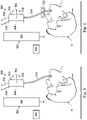
- FIGS. 3 and 4 illustrate a robotic interventional system 200 for use in performing a procedure on a patient PI.
- the robotic interventional system 200 may include any or all of the components of the system 100 but for clarity, only select components are illustrated in FIGS. 3 and 4 .
- the system 200 includes a manipulator assembly 202 (e.g., robotic manipulator assembly 102) controlled by a remote control device 204 (e.g., operator input system 106).
- the manipulator assembly 202 includes an insertion drive 206 and a pitch and/or yaw drive 208.
- the drives 206, 208 may be, for example, servo motor drive mechanisms.
- An interventional instrument 210 includes a handpiece 212 and a flexible body 214 sized for insertion into an anatomic passageway of patient PI.
- An optical fiber 216 passes through the handpiece 212 and the flexible body 214 for measuring the shape of the flexible body or for recording images from the distal end of the flexible body.
- a latching mechanism 218 mechanically couples the handpiece 212 to the manipulator assembly 202.
- the handpiece 212 includes a manual actuator 220.
- the interventional instrument 210 is connected to the manipulator assembly 202 for use in a robotic control mode.
- the insertion drive 206 controls motion of the flexible body 214 in and out of the patient PI in response to a user input at the remote control device 204.
- the drive 208 controls the motion of a distal end of the flexible body 214 in at least one degree of freedom (e.g., pitch, yaw, or roll) in response to user inputs at the remote control device 204.
- the drive 208 may control motion of the distal end of the flexible body 214 in multiple degrees of freedom.
- the insertion and the distal end motion of the interventional instrument is controlled by the remote user via the robotic manipulator assembly.
- the interventional instrument 210 has been disconnected from the manipulator assembly 202 by disengaging the latching mechanism 218 and decoupling the drives of the manipulator assembly 202 from the drive inputs (not shown) of the handpiece.
- the instrument 210 can be held directly by a user, and the user manually advances or withdraws the flexible body 214 to control the insertion of the instrument.
- the user may control roll of the flexible body 214 by rotating the handpiece (e.g., by twisting the user's wrist).
- the user directly toggles the manual actuator 220.
- the actuator 220 may control motion of the distal end of the flexible body 214 in multiple degrees of freedom.
- FIG. 5 illustrates another robotic interventional system 300 for use in performing a procedure on a patient PI.
- the robotic interventional system 300 may include any or all of the components of the system 100 but for clarity, only select components are illustrated in FIG. 5 .
- System 300 includes a manipulator assembly 302 controlled by a remote control device 304.
- the manipulator assembly 302 includes an insertion drive 306.
- An interventional instrument 310 includes a handpiece 312 and a flexible body 314 sized for insertion into an anatomic passageway of patient PI.
- An optical fiber 316 passes through the handpiece 312 and the flexible body 314 for measuring the shape of the flexible body or for recording images from the distal end of the flexible body.
- the handpiece 312 includes a manual actuator 320.
- a drive mechanism 308 includes servo motors for controlling the motion of the distal end of the flexible body 308 in at least one degree of freedom.
- the drive mechanism 308 and interventional instrument 310 may be attached to the manipulator assembly 302 such that the insertion and distal end motion of the instrument is robotically controlled as in FIG. 3 .
- the drive mechanism 308 and the instrument 310 may be detached from the manipulator. When detached, the distal end motion of the instrument may continue to be controlled by the mechanism 308.
- the drive mechanism 308 may be coupled to a power source by a power input 318. Other cables or wireless connections (not shown) may provide control instructions to the drive mechanism 308 from a remote controller.
- the drive mechanism 308 may include batteries or other self-contained portable power supplies to allow untethered use of the instrument 312.
- the drive mechanism 308 may be deactived while still directly attached to the instrument 312 to allow a user to directly toggle the actuator 320 for manually controlling the motion of the distal end of the instrument in at least one degree of freedom.
- FIG. 6 illustrates the robotic interventional system 300 further including an optional insertion drive mechanism 322 coupled to the flexible body 314.
- the insertion-drive mechanism 322 may be portable and may be separately powered and controlled.
- the instrument 310 is detached from the manipulator 302, the advancement and withdrawal of the flexible body 314 from the patient PI may be controlled by the portable insertion drive mechanism 322.
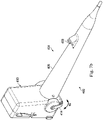
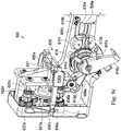
- FIGS. 7a & 7b illustrate an interventional instrument 400 according to another embodiment of the present disclosure.
- the instrument 400 includes an elongated flexible body 402 coupled to a handpiece 404.
- the handpiece 404 includes a grip portion 406, a tool port 408, and interface housing 410.
- the handpiece also includes a plurality of drive inputs 412 for interfacing with the drive system of a robotic manipulator.
- the handpiece 404 further includes a manual actuator 414 pivotable about a pivot 416 for manually controlling the motion of a distal end of the elongated flexible body 402 in at least one degree of freedom (e.g., pitch, yaw, and/or roll).
- degree of freedom e.g., pitch, yaw, and/or roll
- the at least one degree of freedom may be referred to as a pitch motion, but it is understood that one or more manual actuators of the handpiece may control motion of the distal end of the flexible body 402 in one or more other degrees of freedom such as yaw and/or roll.
- the tool port 408 is sized and shaped to receive auxiliary tools for insertion through a channel in the flexible body 402.
- auxiliary tools may include, for example, cameras, biopsy devices, laser ablation fibers, position and orientation sensors or other surgical, diagnostic, or therapeutic tools.
- the grip portion 406 has a tapered shaft sized for comfortable grip by a human hand.
- the grip portion may have ergonomic features such as indentions sized to cradle user fingers or non-slip surfaces.
- the handpiece 404 includes engagement features 418, such as elongated protrusions, that cause the handpiece 404 to couple to the robotic manipulator in a direction D1 that is approximately transverse to the insertion direction D2 of the elongated flexible body 402.
- the transverse coupling direction reduces the risk that coupling the handpiece to the manipulator will move the distal end of the flexible body in the insertion direction D2, thus reducing the risk of injury to the patient or disrupting the navigation that would otherwise result from inadvertent advancement or retraction of the flexible body within the tiny and delicate anatomical passageways of the patient.
- engagement features may be provided that would cause the handpiece 404 to couple to the robotic manipulator in a direction D3 that is also approximately transverse to the insertion direction D2 of the elongated flexible body 502.
- the transverse coupling direction would also reduce the risk of moving the handpiece in direction D2 when coupling the handpiece to the robotic manipulator.
- a user grasps the grip portion 406 of the instrument 400 and holds the handpiece 404 such that the user's thumb rests near or against the manual actuator 414.
- the user manually controls insertion motion (i.e., in the direction D2) by advancing or withdrawing the handpiece 404 relative to the patient's anatomy.
- the user manually controls the pitch motion M1 by pivoting the manual actuator 414 with the motion M2.
- pivoting the manual actuator toward the distal end of the instrument pitches the distal end of the flexible body up
- pivoting the manual actuator toward the proximal end of the instrument pitches the distal end of the flexible body down.
- the motion of the manual actuator may cause the pitch motions in the opposite directions.
- the motion of the manual actuator may cause motion of the distal end of the flexible body in other degrees of freedom such as yaw or roll.
- the instrument 400 is directly connected to the robotic manipulator.
- the drive inputs 412 provide mechanical coupling of the end effector and flexible body steering mechanism with the drive motors mounted to the manipulator.
- a pair of drive inputs may control the pitch motion M1 of the distal end of the flexible body, with one adaptor of the pair controlling motion in the upward direction and the other of the pair controlling motion in the opposite downward direction.
- Other pairs of drive inputs may provide opposing motion in other degrees of freedom for the flexible body and/or the end effector.
- Instrument interfacing with robotic manipulators is described, for example in U.S. Patent No. 6,331,181, filed October 15 1999 , disclosing "Surgical Robotic Tools, Data Architecture, And Use" and U.S. Patent No. 6,491,701, filed January 12, 2001 disclosing "Mechanical Actuator Interface System For Robotic Surgical Tools".
- FIG. 8 illustrates an interventional instrument 500 according to another embodiment of the present disclosure.
- the instrument 500 includes an elongated flexible body 502 coupled to a handpiece 504.
- the handpiece 504 includes a grip portion 506, a tool port 508, and interface housing 510.
- the handpiece also includes a plurality of drive inputs 512 for interfacing with the drive system of a robotic manipulator.
- the handpiece 504 further includes a manual actuator 514 pivotable about a pivot 516 for manually controlling the motion of a distal end of the elongated flexible body 502.
- the manual actuator 514 includes two levers (not clearly shown in FIG. 8 , but see similar configuration in FIG. 9b ). Each of the levers controls opposing motions of a single degree of freedom, e.g, pitch motion. Alternatively, one pivoting lever can control opposing yaw motions and the other pivoting lever can control opposing pitch motions of the distal end of the flexible body.
- the tool port 508 is sized and shaped to receive auxiliary tools for insertion through a channel in the flexible body 502.
- auxiliary tools may include, for example, cameras, biopsy devices, laser ablation fibers, position and orientation sensors or other surgical, diagnostic, or therapeutic tools.
- the grip portion 506 has a tapered shaft sized for comfortable grip by a human hand.
- the grip portion may have ergonomic features such as indentions sized to cradle user fingers or non-slip surfaces.
- engagement features such as elongated protrusions 518, enable the handpiece 504 to couple to the robotic manipulator in the direction D1 that is approximately transverse to the insertion direction D2 of the elongated flexible body 502.
- the transverse coupling direction reduces the risk that coupling the handpiece manipulator will move the distal end of the flexible body in the insertion direction D2, thus reducing the risk of injury to the patient or disrupting the navigation that would otherwise result from inadvertent advancement or retraction of the flexible body within the tiny and delicate anatomical passageways of the patient.
- the handpiece 504 further includes an unlatching mechanism for removing the instrument 500 from the robotic manipulator.
- the unlatching mechanism includes a pair of tabs 520 connected by a biasing member (e.g. an extension spring) and connected to a pair of links 522.
- a biasing member e.g. an extension spring
- the handpiece 504 When the handpiece 504 is coupled to the robotic manipulator, squeezing the tabs 520 together moves the links toward the robotic manipulator, disengaging the handpiece inputs 512 from the robotic manipulator. Then the handpiece 504 may be disengaged from the robotic manipulator, and after disengagement, the instrument 500 may be operated in manual mode.
- the actuation of the instrument 500 in manual and robotic control modes is similar to the actuation described above for instrument 400 except that the dual lever manual actuator 514 permits a user, in manual mode, to control opposing motions of a single degree of freedom of the distal end of the flexible body (e.g. pitch up and pitch down).
- a dual lever manual actuator may be configured so that each of the two levers controls a different degree of freedom in two directions (e.g., the right lever controls pitch up and down and the left lever controls yaw left and right).
- FIG. 1 a manual actuator 24 is manipulated by a user to control motion of the distal end of the flexible body when the handpiece 14 is used in manual mode.
- FIGS. 9a , 10 , and 11a illustrate different embodiments for the manual actuator. In other respects, FIGS. 9a , 10a, and 11 are similar to FIG. 1 .
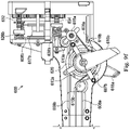
- FIG. 9a schematically illustrates an interventional instrument 600 and FIGS. 9b , 9c , 9d , 9e , 9f , and 9g illustrate an implementation of the interventional instrument 600 schematically illustrated in FIG. 9a .
- the system 600 includes a catheter system 602 coupled to an instrument handpiece 604 which includes a grip portion 603.
- the catheter system 602 includes an elongated flexible body 606.
- the flexible body 606 houses opposing drive components 608a, 608b for moving the distal end of the flexible body in opposite directions in one degree of freedom (e.g, pitch degree of freedom motion).
- the flexible body 606 also houses opposing drive components 610a, 610b for moving the distal end of the flexible body in opposite directions in another degree of freedom (e.g. yaw degree of freedom).
- the drive components are tendons, such as pull wires, that extend from the instrument handpiece 604 to the distal end of the flexible body.
- the instrument handpiece 604 includes frame 611 and pulleys 612a, 612b, 613a, 614a, 614b, 615a, 615b rotatably coupled to the frame. Alignment mechanisms 617a, 617b are also coupled to the frame 611.
- the handpiece 604 further includes a manual actuator 619 that includes a lever 616a mechanically linked to a capstan mechanism 618.
- the manual actuator 619 also includes a lever 616b mechanically linked to a capstan mechanism 620.
- a biasing member 625 such as a spring, extends between the capstan mechanisms 618, 620.
- the instrument handpiece 604 further includes a drive input 622a movable by a motorized drive system 624 to control the movement of the drive component 608a in one direction of a degree of freedom (e.g., pitch down).
- the handpiece 604 also includes a drive input 626a movable by a motorized drive system 628 to control the movement of drive component 608b in an opposite direction of the same degree of freedom (e.g., pitch up).
- the drive systems 624, 628 are components of the robotic manipulator that includes the drive motors.
- the drive input 622a includes a disk shaped engagement portion 622b and an input shaft portion 622c. A helical groove drive capstan 622d is supported by the shaft portion 622c.
- the engagement portion 622b may be removably coupled to the drive system 624.
- the input shaft portion 622c is integrally formed or fixedly coupled to the engagement portion 622b.
- the drive input 626a includes an engagement portion 622b and an input shaft portion 626c.
- a helical groove drive capstan 626d is supported by the shaft portion 626c.
- the engagement portion 626b may be removably coupled to the drive system 628.
- the input shaft portion 626c is integrally formed or fixedly coupled to the engagement portion 626b.
- the instrument handpiece 604 further includes a tensioning system 632 (e.g., a pitch tensioning system) which prevents the opposing drive components 608a, 608b from becoming slack and decoupling from or entangling about the drive input capstans, pulleys, or lever capstan mechanisms.
- a tensioning system 632 e.g., a pitch tensioning system
- the instrument handpiece 604 further includes a drive input 636a movable by a motorized drive system 637 to control the movement of the drive component 610a in one direction of a degree of freedom (e.g., yaw right).
- a helical groove drive capstan 636b is connected to the drive input 636a.
- the handpiece 604 also includes a drive input 638a movable by a motorized drive system 639 to control the movement of drive component 610b in an opposite direction of the same degree of freedom (e.g., yaw left).
- a helical groove drive capstan 638b is connected to the drive input 638a.
- the drive systems 637, 639 are components of the robotic manipulator that includes the drive motors.
- the instrument handpiece 604 further includes a tensioning system 634 (e.g., a yaw tensioning system) which prevents the opposing drive components 610a, 610b from becoming slack and decoupling from the drive inputs capstans or the pulleys.
- a tensioning system 634 e.g., a yaw tensioning system
- the operation of a gear-based tensioning system such as systems 632, 634 will be described in greater detail for FIGS. 12a, 12b .
- each of the drive components 608a, 608b, 610a, and 610b includes a pull wire portion extending through distal end of the instrument handpiece 604 and into the flexible body 606.
- the wire portion is coupled, for example by crimping, to a cable portion that extends between the drive input and the wire portion.
- the cable portion may resist kinks, allowing the drive component to traverse the tight turns in the pulley system of the handpiece.
- the drive components may be formed from a continuous length of tendon.
- a cable portion of the pitch down drive component 608a is wound around the drive capstan 622d and over a portion of the alignment mechanism 617a to align the drive component with the pulley 612a.
- the drive component 608a is bent to an angle between approximately 90° and 135° around the pulley 612a.
- the angles of the cables formed by the pulleys may be larger or smaller.
- the drive component 608a extends around and is fixed to the lever capstan mechanism 618. Another length of cable of the drive component is fixed to the lever capstan mechanism 618 and extends over the pulley 612b and is crimped to the pull wire portion of the drive component 608a.
- the cable portion may be continuous without separate portions fixed to the capstan 618.
- a cable portion of the pitch up drive component 608b is wound around the drive capstan 626b and over a portion of the alignment mechanism 617b to align the drive component with the pulley 613a.
- the drive component 608b is bent to an angle of approximately 90° around the pulley 613a.
- the drive component extends around and is fixed to the lever capstan mechanism 620.
- Another length of cable of the drive component is fixed to the lever capstan mechanism 620 and is crimped to the pull wire portion of the drive component 608b.
- the cable portion may be continuous without separate portions fixed to the capstan 620.
- a cable portion of the yaw right drive component 610a is wound around the drive capstan 636b, extends over a pulley 607a and at least partially around the pulley 614b, and is crimped to the pull wire portion of the drive component 610a.
- a cable portion of the yaw left drive component 610b is wound around the drive capstan 638b, at least partially around the pulley 615a, at least partially around the pulley 607b, and at least partially around the pulley 615b. The cable portion is then crimped to the pull wire portion of the drive component 610b.
- the various capstans, alignment mechanisms, and pulleys serve to keep the cables untangled, aligned, and free of kinks as the cables traverse the handpiece between the drive inputs and the catheter system. Because the axes of the drive input shafts (e.g., axis A1 of shaft 622c) are generally perpendicular with the axis A2 of the grip portion 603, the drive components may bend at least once at an approximate right angle along their paths within the handpiece 604.
- a clinician grips the grip portion 603 of the handpiece 604 with a thumb positioned near the levers 616a and 616b.
- the clinician can control a range of motion (e.g., pitch, roll, and insertion) of the distal end 605 of the catheter 602.
- the clinician pushes the lever 616a (e.g., clockwise in FIG. 9b ) which transmits a rotational motion to the lever capstan 618.
- Rotation of the lever capstan 618 retracts the drive component 608a, causing the distal end 605 of the catheter 602 to pitch downward.
- the lever 616a may include differently angled surfaces or other tactile cues to allow the clinician to easily recognize the direction of motion associated with each lever.
- the clinician pushes the lever 616b (e.g., clockwise in FIG. 9e ) which transmits a rotational motion to the lever capstan 620.
- Rotation of the lever capstan 620 retracts the drive component 608b, causing the distal end 605 of the catheter 602 to pitch upward.
- the roll of the distal end 605 of the catheter 602 about axis A2 is controlled by bending of the clinician's wrist.
- the insertion of the distal end 605 of the catheter 602 is controlled by clinician advancing or retracting the handpiece 604 relative to the patient.
- the drive inputs 622a, 626a, 636a, 638a are coupled to motorized drive systems 624, 628, 637, 639, respectively, of a robotic manipulator.
- coupling of the drive inputs and drive systems may occur in a direction transverse to the insertion axis A2 to reduce the risk of advancing or retracting the distal end 605 of the catheter 602.
- the clinician can control a range of motion (e.g., pitch, yaw, roll, and insertion) of the distal end 605 of the catheter 602.
- Movement of the drive input 622a turns the capstan 622d and retracts the drive component 608a, causing the distal end 605 of the catheter 602 to pitch downward.
- Movement of the drive input 626a turns the capstan 626b and retracts the drive component 608b, causing the distal end 605 of the catheter 602 to pitch upward.
- Movement of the drive input 636a turns the capstan 636b and retracts the drive component 610a, causing the distal end 605 of the catheter 602 to yaw rightward.
- Movement of the drive input 638a turns the capstan 638b and retracts the drive component 610b, causing the distal end 605 of the catheter 602 to yaw leftward.
- the roll and insertion of the distal end 605 of the catheter 602 is controlled by movement of the robotic manipulator.
- the tabs 630a of the unlatching mechanism 630 are squeezed, compressing spring 631 (See. FIG. 9c ). Squeezing the tabs together moves the links 630b toward the robotic manipulator, optionally moving a plate carrying adaptors such as 27 and 29 of FIG. 1 , disengaging the drive inputs from the drive systems and allowing disengagement of hand piece 604 from the robotic manipulator in a direction transverse to axis A2 of body 606.
- the handpiece 604 also includes a tool port 640 sized and shaped to receive auxiliary tools for insertion through a channel in the flexible body 606. The location of the tool port may be determined to accommodate the drive components and the clinician's grip.
- the handpiece 604 also includes a collar 641 coupling the flexible body 616 to the grip portion 603. At least a portion of the drive components 608a, 608b, 610a, 610b may be formed of Bowden cable 643 having an elongated inner component (e.g., a wire or cable) movable with respect to and an elongated outer coiled sheath.
- the inner component may be crimped to the cable portions of the drive components as previously explained.
- a stud component 642 is attached to the outer coiled sheath (e.g., by epoxy) and is held fixed relative to the grip portion 603 by a clamping plate 644 held in place by fastener 645.
- the Bowden cable portions of the drive components may flex and bulge out through slots 646 ( FIG. 9b ) in the handpiece 604. This is because with the outer coiled sheath constrained at the proximal end clamping plate is constrained from axial movement along the axis A2.
- FIG. 10 schematically illustrates an interventional instrument 650.
- the interventional instrument has a manual actuator with a single control lever and a tensioning system coupled between opposing drive components.
- the system 650 includes a catheter system 652 coupled to an instrument handpiece 654.
- the catheter system 652 includes an elongated flexible body 656.
- the flexible body 656 houses opposing drive components 658a, 658b for moving the distal end of the flexible body in opposite directions in one degree of freedom (e.g, pitch degree of freedom motion).
- the instrument handpiece 654 includes a manual action lever capstan system 660 similar to one of the lever capstan systems 616b/620, 616a/618 of manual actuator 619 disclosed for FIG. 9a .
- the lever capstan system 660 is coupled to a single lever 662 for manual actuation by a user. Together the lever 662 and lever capstan system 660 form a manual actuator.
- the instrument handpiece 654 includes a drive input 664 movable by a drive system 666 to control the movement of the drive component 658a.
- the instrument handpiece 654 also includes a drive input 668 movable by a drive system 670 to control the movement of the opposing drive component 658b.
- the drive systems 666, 670 are components of the robotic manipulator that includes the drive motors.
- the instrument handpiece 654 further includes a tensioning system 672 which prevents the opposing drive components 658a, 658b from becoming slack and decoupling from or entangling about the drive inputs or cable wheel system
- a clinician operates the single lever 662 to control both opposing motions for a single degree of freedom. For example, advancing the lever may move a distal end of the flexible body to pitch up and retracting the lever may move a distal end of the flexible body to pitch down.
- the instrument system 650 is coupled to a robotic manipulator for control in a manner similar to that described for instrument system 600.
- the drive system of the robotic manipulator controls only opposing motions for a single degree of freedom, e.g. pitch up and down.
- a second drive input set and tensioning system similar to that disclosed for instrument system 600 may be used to robotically control opposing motions for a second degree of freedom, e.g. yaw right and left.
- FIG. 11a schematically illustrates such a second degree of freedom drive input set and tensioning system in an interventional instrument 675
- FIG. 11b illustrates an implementation of the interventional instrument schematically illustrated in FIG. 11a
- the system 675 includes a catheter system 677 coupled to an instrument handpiece 679.
- the catheter system 12 includes an elongated flexible body 681.
- the flexible body 681 houses opposing drive components 683a, 683b for moving the distal end of the flexible body in opposite directions of a single degree of motion (e.g., pitch).
- the flexible body 681 also houses opposing drive components 685a, 685b for moving the distal end of the flexible body in opposite directions of another single degree of motion (e.g., yaw).
- the handpiece 679 includes a pitch control system 684 including drive inputs and a pitch tensioning system similar to that described for handpiece 600.
- the handpiece 679 also includes a yaw control system 686 including drive inputs and a yaw tensioning system similar to that described for handpiece 600.
- a manual actuator 688 includes a single lever 691 mechanically linked to a pinion gear 693 that is mechanically engaged with gear racks 695.
- the opposing pitch drive components 683a, 683b are coupled to the gear racks 695.
- the instrument system 675 may be operated substantially as described for instrument system 600.
- a clinician operates the lever 691, for example with a thumb, to move the opposing pitch drive components 683a, 683b.
- pivoting the lever 691 toward the distal end of the handpiece 679 rotates the gear 693, causing the rack and pinion arms to move in opposite directions, thereby retracting the drive component 683b and advancing the drive component 683a.
- the gear 693 rotates, causing the rack and pinion arms to move in opposite directions, thereby retracting the drive component 683a and advancing the drive component 683b.
- drive inputs in the handpiece may be coupled to the motorized drive system of the robotic interventional system so that in robotic control mode the drive inputs control multiple degrees of freedom (e.g., pitch and yaw) while in manual mode fewer degrees of freedom may be controlled by the manual actuator (e.g. pitch only).
- the same number of degrees of freedom can be controlled in both manual and robotic control.
- FIG. 12a schematically illustrates an interventional instrument 700.
- the instrument 700 includes a catheter system 702 coupled to an instrument handpiece 704.
- the catheter system 702 houses opposing drive components 706a, 706b for moving the distal end of the flexible body in opposite directions in one degree of freedom (e.g, pitch degree of freedom motion).
- the instrument 700 has a gear and spring tensioning system 708 which prevents the opposing drive components 706a, 706b from becoming slack and decoupling from or entangling about the drive inputs or manual actuator. Similar tensioning systems 632, 634 are used in instrument system 600.
- FIG. 12b illustrates a portion of the tensioning system 708 which includes a gear 710 coupled to a gear 714 by an idling gear 712.
- the tensioning system 708 may be applied as the tensioning system in any of the instrument systems previously described.
- Gear 710 is rotatably coupled to a shaft 711 which is rotatably attached to the handpiece 704.
- a biasing member 716 such as a torsion spring, is coupled at one end to the gear 710 and at another end to a capstan 718 which is fixed to shaft 711.
- the drive component 706b wraps around the capstan 718.
- gear 714 is rotatably coupled to a shaft 713 which is rotatably attached to handpiece 704.
- a biasing member 720 such as a torsion spring, is coupled at one end to the gear 714 and at another end to a capstan 722 which is fixed to shaft 713.
- the drive component 706a wraps around the capstan 722.
- Capstan 718 is therefore compliantly coupled to capstan 722 through the gears 710, 712, 714 and the springs 716, 720.
- drive component 706b is compliantly coupled through tensioning system 708 to the drive component 706a.
- the gear and spring tensioning system 708 is assembled with a torsional preload on the springs 716, 720 to apply tension to drive components 706a, 706b, the springs are able to compensate for slack that may develop between the drive components when, for example, the drive systems are decoupled and no torque is applied to the drive inputs.
- Tensioning systems such as 708 may also maintain tension between drive components (e.g., drive components 608a, 608b of handpiece 604) when unequal motion of the drive components occurs due to friction and axial compliance in drive components 608a, 608b or catheter 602 or due to bending of catheter 602.
- drive components e.g., drive components 608a, 608b of handpiece 604
- unequal motion of the drive components occurs due to friction and axial compliance in drive components 608a, 608b or catheter 602 or due to bending of catheter 602.
- the opposing drive component 706b unfurls at least partially as capstan 718 rotates. Via the spring 716, at least some of the torque on the capstan 718 is transferred to gear 710. The torque on gear 710 applies torque to gear 714 in the same direction. The torque on the gear 714 is imparted at least partially, via spring 720 to capstan 722 to prevent any slack from appearing in opposing drive component 706a. Thus, opposing drive components 706a, 706b are maintained in tension.
- tensioning system 708 with unequal motions of opposing drive components may be particularly applicable in the instrument system 600 because the unequal motions of the drive components 608a, 608b can find their way past the split lever capstan system of manual actuator 619 to affect cable slack in the inputs.
- FIG. 13a schematically illustrates an interventional instrument 750.
- the instrument 750 includes a catheter system 752 coupled to an instrument handpiece 754.
- the catheter system 752 houses opposing drive components 756a, 756b for moving the distal end of the flexible body in opposite directions in one degree of freedom (e.g, pitch degree of freedom motion).
- the instrument 750 has a cable tensioning system 758 which prevents the opposing drive components 756a, 756b from becoming slack and decoupling from the drive inputs or manual actuator.
- FIG. 13b illustrates a portion of the tensioning system 758 which includes a capstan 766 coupled to a capstan 768 by a cable 774 fixed to and wound at least partially around the capstans.
- Capstan 766 is rotatably coupled to a shaft 770 which is rotatably attached to the handpiece 754.
- a biasing member 762 such as a torsion spring, is supported by the shaft 770 and coupled at one end to the capstan 766 and at another end to a capstan 760.
- the drive component 756b wraps around the capstan 760.
- capstan 768 is rotatably coupled to a shaft 772 which is rotatably attached to the handpiece 754.
- a biasing member 764 such as a torsion spring, is coupled at one end to the capstan 768 and at another end to a capstan 762.
- the drive component 756a wraps around the capstan 762.
- Pre-load wind-up of torsion springs 762, 764 maintain tension in drive components 756a, 756b when no torque or lock is applied to the drive inputs or when unequal motions of the drive components would otherwise create slack.
- the opposing drive component 756b unfurls at least partially as capstan 756 rotates.
- the spring 762 at least some of the torque on the capstan 760 is transferred to capstan 766.
- the torque on capstan 766 is imparted at least partially, via cable 774 to apply torque to capstan 768.
- Torque on the capstan 768 is imparted at least partially through spring 764 to apply torque to capstan 762 to prevent any slack created in opposing drive component 756a.
- opposing drive components 756a, 756b are maintained in tension.
- FIG. 14a schematically illustrates an interventional instrument 800.
- the instrument 800 includes a flexible body 802 coupled to an instrument handpiece 804.
- the flexible body 802 houses opposing drive components 806a, 806b for moving the distal end of the flexible body in opposite directions in one degree of freedom (e.g, pitch degree of freedom motion).
- the instrument 800 has a pulley and spring tensioning system 808 which prevents the opposing drive components 806a, 806b from becoming slack and decoupling from or entangling about the drive inputs or manual actuator.
- FIG. 14b illustrates a portion of the tensioning system 808 which includes a pulley 810 fixed to the handpiece 804.
- a biasing member 812 such as an extension spring, is attached between the drive components 806a, 806b. At least one of the drive components 806a, 806b extends across the pulley 810.
- the spring 812 is pre-loaded so that if the movements of the drive components 806a, 806b are not equal or if no torque is applied to the inputs, at least some tension in both drive components is maintained. This insures that the drive components do not become disengaged from or entangled about the pulleys or capstans of the tensioning systems or the drive inputs or manual actuator.
- the opposing drive component 756b unfurls at least partially as capstan 756 rotates. Via the spring 762, at least some of the torque is applied to the capstan 760 is transmitted to capstan 766. The movement of capstan 766 is imparted at least partially, via cable 774 to rotate capstan 768. Rotation of the capstan 768 is imparted at least partially through spring 764 to rotate capstan 762 to take up any slack created in opposing drive component 756a. Thus, opposing drive components 756a, 756b are maintained in tension.
- FIG. 15 illustrates a method of use for an interventional instrument according to an embodiment of the present disclosure.
- An interventional instrument such as any of those described in the preceding embodiments, is provided at 852.
- the instrument may be operated in manual mode.
- the manual actuator of the interventional instrument receives a force from the user (e.g., the pressure of a user's thumb against a thumb lever) to move the distal end of the elongated flexible instrument.
- a force from the user e.g., the pressure of a user's thumb against a thumb lever
- the manual actuator moves a first drive component to control movement of a distal end of the elongated flexible shaft in a first direction (e.g., an upward pitch direction).
- the manual actuator moves a second drive component to control movement of the distal end of the elongated flexible shaft in a second direction, opposite the first direction (e.g., a downward pitch direction).
- the interventional instrument is coupled to a robotic surgical system. More specifically, a motorized drive mechanism of a robotic surgical system receives a motor interface of the interventional instrument. Optionally, the motor interface of the interventional instrument is received at the drive mechanism in a direction approximately transverse to the longitudinal axis of the elongated shaft of the interventional instrument to minimize or eliminate motion of the instrument along its axis of insertion into the patient.
- the drive input of the motorized mechanism is activated to move the distal end of the elongated flexible shaft in a first degree of freedom (e.g., pitch).
- one of a pair of drive inputs of the interventional instrument receives a force from the motorized drive system to move the distal end of the elongated flexible instrument.
- one of the pair of drive inputs moves a first drive component to control movement of a distal end of the elongated flexible shaft in a first direction (e.g., an upward pitch direction).
- the other one of the pair of drive inputs moves a second drive component to control movement of the distal end of the elongated flexible shaft in a second direction, opposite the first direction (e.g., a downward pitch direction).
- the motor interface of the interventional instrument is decoupled from the drive mechanism.
- the motor interface of the interventional instrument is decoupled in a direction transverse to the longitudinal axis of the elongated shaft. Coupling and decoupling the instrument from the drive mechanism in a direction transverse to the shaft reduces the risk that the distal end interventional instrument will change insertion depth as the instrument moves between robotic control mode and manual control mode.
- One or more elements in embodiments of the invention may be implemented in software to execute on a processor of a computer system such as control system 116.
- the elements of the embodiments of the invention are essentially the code segments to perform the necessary tasks.
- the program or code segments can be stored in a processor readable storage medium or device that may have been downloaded by way of a computer data signal embodied in a carrier wave over a transmission medium or a communication link.
- the processor readable storage device may include any medium that can store information including an optical medium, semiconductor medium, and magnetic medium.
- Processor readable storage device examples include an electronic circuit; a semiconductor device, a semiconductor memory device, a read only memory (ROM), a flash memory, an erasable programmable read only memory (EPROM); a floppy diskette, a CD-ROM, an optical disk, a hard disk, or other storage device,
- the code segments may be downloaded via computer networks such as the Internet, intranet, etc.
Landscapes
- Health & Medical Sciences (AREA)
- Life Sciences & Earth Sciences (AREA)
- Surgery (AREA)
- Engineering & Computer Science (AREA)
- Medical Informatics (AREA)
- Nuclear Medicine, Radiotherapy & Molecular Imaging (AREA)
- Biomedical Technology (AREA)
- Heart & Thoracic Surgery (AREA)
- Molecular Biology (AREA)
- Animal Behavior & Ethology (AREA)
- General Health & Medical Sciences (AREA)
- Public Health (AREA)
- Veterinary Medicine (AREA)
- Robotics (AREA)
- Ophthalmology & Optometry (AREA)
- Manipulator (AREA)
- Surgical Instruments (AREA)
Priority Applications (1)
| Application Number | Priority Date | Filing Date | Title |
|---|---|---|---|
| EP22164228.3A EP4035615B1 (en) | 2013-03-07 | 2014-03-06 | Hybrid manual and robotic interventional instruments |
Applications Claiming Priority (3)
| Application Number | Priority Date | Filing Date | Title |
|---|---|---|---|
| US201361774385P | 2013-03-07 | 2013-03-07 | |
| US14/197,325 US9839481B2 (en) | 2013-03-07 | 2014-03-05 | Hybrid manual and robotic interventional instruments and methods of use |
| PCT/US2014/021126 WO2014138365A1 (en) | 2013-03-07 | 2014-03-06 | Hybrid manual and robotic interventional instruments and methods of use |
Related Child Applications (2)
| Application Number | Title | Priority Date | Filing Date |
|---|---|---|---|
| EP22164228.3A Division EP4035615B1 (en) | 2013-03-07 | 2014-03-06 | Hybrid manual and robotic interventional instruments |
| EP22164228.3A Division-Into EP4035615B1 (en) | 2013-03-07 | 2014-03-06 | Hybrid manual and robotic interventional instruments |
Publications (3)
| Publication Number | Publication Date |
|---|---|
| EP2964123A1 EP2964123A1 (en) | 2016-01-13 |
| EP2964123A4 EP2964123A4 (en) | 2016-11-23 |
| EP2964123B1 true EP2964123B1 (en) | 2022-05-04 |
Family
ID=51488733
Family Applications (2)
| Application Number | Title | Priority Date | Filing Date |
|---|---|---|---|
| EP14760153.8A Active EP2964123B1 (en) | 2013-03-07 | 2014-03-06 | Hybrid manual and robotic interventional instruments |
| EP22164228.3A Active EP4035615B1 (en) | 2013-03-07 | 2014-03-06 | Hybrid manual and robotic interventional instruments |
Family Applications After (1)
| Application Number | Title | Priority Date | Filing Date |
|---|---|---|---|
| EP22164228.3A Active EP4035615B1 (en) | 2013-03-07 | 2014-03-06 | Hybrid manual and robotic interventional instruments |
Country Status (6)
| Country | Link |
|---|---|
| US (1) | US9839481B2 (OSRAM) |
| EP (2) | EP2964123B1 (OSRAM) |
| JP (1) | JP6453777B2 (OSRAM) |
| KR (1) | KR102241089B1 (OSRAM) |
| CN (1) | CN105025829B (OSRAM) |
| WO (1) | WO2014138365A1 (OSRAM) |
Families Citing this family (488)
| Publication number | Priority date | Publication date | Assignee | Title |
|---|---|---|---|---|
| US9060770B2 (en) | 2003-05-20 | 2015-06-23 | Ethicon Endo-Surgery, Inc. | Robotically-driven surgical instrument with E-beam driver |
| US20070084897A1 (en) | 2003-05-20 | 2007-04-19 | Shelton Frederick E Iv | Articulating surgical stapling instrument incorporating a two-piece e-beam firing mechanism |
| US11890012B2 (en) | 2004-07-28 | 2024-02-06 | Cilag Gmbh International | Staple cartridge comprising cartridge body and attached support |
| US9072535B2 (en) | 2011-05-27 | 2015-07-07 | Ethicon Endo-Surgery, Inc. | Surgical stapling instruments with rotatable staple deployment arrangements |
| US8496647B2 (en) | 2007-12-18 | 2013-07-30 | Intuitive Surgical Operations, Inc. | Ribbed force sensor |
| US8465474B2 (en) | 2009-05-19 | 2013-06-18 | Intuitive Surgical Operations, Inc. | Cleaning of a surgical instrument force sensor |
| US11246590B2 (en) | 2005-08-31 | 2022-02-15 | Cilag Gmbh International | Staple cartridge including staple drivers having different unfired heights |
| US11484312B2 (en) | 2005-08-31 | 2022-11-01 | Cilag Gmbh International | Staple cartridge comprising a staple driver arrangement |
| US7669746B2 (en) | 2005-08-31 | 2010-03-02 | Ethicon Endo-Surgery, Inc. | Staple cartridges for forming staples having differing formed staple heights |
| US10159482B2 (en) | 2005-08-31 | 2018-12-25 | Ethicon Llc | Fastener cartridge assembly comprising a fixed anvil and different staple heights |
| US7934630B2 (en) | 2005-08-31 | 2011-05-03 | Ethicon Endo-Surgery, Inc. | Staple cartridges for forming staples having differing formed staple heights |
| US20070106317A1 (en) | 2005-11-09 | 2007-05-10 | Shelton Frederick E Iv | Hydraulically and electrically actuated articulation joints for surgical instruments |
| US8628518B2 (en) | 2005-12-30 | 2014-01-14 | Intuitive Surgical Operations, Inc. | Wireless force sensor on a distal portion of a surgical instrument and method |
| US7845537B2 (en) | 2006-01-31 | 2010-12-07 | Ethicon Endo-Surgery, Inc. | Surgical instrument having recording capabilities |
| US8186555B2 (en) | 2006-01-31 | 2012-05-29 | Ethicon Endo-Surgery, Inc. | Motor-driven surgical cutting and fastening instrument with mechanical closure system |
| US7753904B2 (en) | 2006-01-31 | 2010-07-13 | Ethicon Endo-Surgery, Inc. | Endoscopic surgical instrument with a handle that can articulate with respect to the shaft |
| US11793518B2 (en) | 2006-01-31 | 2023-10-24 | Cilag Gmbh International | Powered surgical instruments with firing system lockout arrangements |
| US20110290856A1 (en) | 2006-01-31 | 2011-12-01 | Ethicon Endo-Surgery, Inc. | Robotically-controlled surgical instrument with force-feedback capabilities |
| US8820603B2 (en) | 2006-01-31 | 2014-09-02 | Ethicon Endo-Surgery, Inc. | Accessing data stored in a memory of a surgical instrument |
| US20120292367A1 (en) | 2006-01-31 | 2012-11-22 | Ethicon Endo-Surgery, Inc. | Robotically-controlled end effector |
| US8708213B2 (en) | 2006-01-31 | 2014-04-29 | Ethicon Endo-Surgery, Inc. | Surgical instrument having a feedback system |
| US11278279B2 (en) | 2006-01-31 | 2022-03-22 | Cilag Gmbh International | Surgical instrument assembly |
| US8992422B2 (en) | 2006-03-23 | 2015-03-31 | Ethicon Endo-Surgery, Inc. | Robotically-controlled endoscopic accessory channel |
| US10568652B2 (en) | 2006-09-29 | 2020-02-25 | Ethicon Llc | Surgical staples having attached drivers of different heights and stapling instruments for deploying the same |
| US11980366B2 (en) | 2006-10-03 | 2024-05-14 | Cilag Gmbh International | Surgical instrument |
| US8684253B2 (en) | 2007-01-10 | 2014-04-01 | Ethicon Endo-Surgery, Inc. | Surgical instrument with wireless communication between a control unit of a robotic system and remote sensor |
| US8632535B2 (en) | 2007-01-10 | 2014-01-21 | Ethicon Endo-Surgery, Inc. | Interlock and surgical instrument including same |
| US11291441B2 (en) | 2007-01-10 | 2022-04-05 | Cilag Gmbh International | Surgical instrument with wireless communication between control unit and remote sensor |
| US20080169332A1 (en) | 2007-01-11 | 2008-07-17 | Shelton Frederick E | Surgical stapling device with a curved cutting member |
| US8727197B2 (en) | 2007-03-15 | 2014-05-20 | Ethicon Endo-Surgery, Inc. | Staple cartridge cavity configuration with cooperative surgical staple |
| US8931682B2 (en) | 2007-06-04 | 2015-01-13 | Ethicon Endo-Surgery, Inc. | Robotically-controlled shaft based rotary drive systems for surgical instruments |
| US11672531B2 (en) | 2007-06-04 | 2023-06-13 | Cilag Gmbh International | Rotary drive systems for surgical instruments |
| US7753245B2 (en) | 2007-06-22 | 2010-07-13 | Ethicon Endo-Surgery, Inc. | Surgical stapling instruments |
| US11849941B2 (en) | 2007-06-29 | 2023-12-26 | Cilag Gmbh International | Staple cartridge having staple cavities extending at a transverse angle relative to a longitudinal cartridge axis |
| US8561473B2 (en) | 2007-12-18 | 2013-10-22 | Intuitive Surgical Operations, Inc. | Force sensor temperature compensation |
| US8636736B2 (en) | 2008-02-14 | 2014-01-28 | Ethicon Endo-Surgery, Inc. | Motorized surgical cutting and fastening instrument |
| US7866527B2 (en) | 2008-02-14 | 2011-01-11 | Ethicon Endo-Surgery, Inc. | Surgical stapling apparatus with interlockable firing system |
| JP5410110B2 (ja) | 2008-02-14 | 2014-02-05 | エシコン・エンド−サージェリィ・インコーポレイテッド | Rf電極を有する外科用切断・固定器具 |
| US11986183B2 (en) | 2008-02-14 | 2024-05-21 | Cilag Gmbh International | Surgical cutting and fastening instrument comprising a plurality of sensors to measure an electrical parameter |
| US8573465B2 (en) | 2008-02-14 | 2013-11-05 | Ethicon Endo-Surgery, Inc. | Robotically-controlled surgical end effector system with rotary actuated closure systems |
| US9179912B2 (en) | 2008-02-14 | 2015-11-10 | Ethicon Endo-Surgery, Inc. | Robotically-controlled motorized surgical cutting and fastening instrument |
| US7819298B2 (en) | 2008-02-14 | 2010-10-26 | Ethicon Endo-Surgery, Inc. | Surgical stapling apparatus with control features operable with one hand |
| US9770245B2 (en) | 2008-02-15 | 2017-09-26 | Ethicon Llc | Layer arrangements for surgical staple cartridges |
| US9204923B2 (en) | 2008-07-16 | 2015-12-08 | Intuitive Surgical Operations, Inc. | Medical instrument electronically energized using drive cables |
| US9386983B2 (en) | 2008-09-23 | 2016-07-12 | Ethicon Endo-Surgery, Llc | Robotically-controlled motorized surgical instrument |
| US8210411B2 (en) | 2008-09-23 | 2012-07-03 | Ethicon Endo-Surgery, Inc. | Motor-driven surgical cutting instrument |
| US11648005B2 (en) | 2008-09-23 | 2023-05-16 | Cilag Gmbh International | Robotically-controlled motorized surgical instrument with an end effector |
| US9005230B2 (en) | 2008-09-23 | 2015-04-14 | Ethicon Endo-Surgery, Inc. | Motorized surgical instrument |
| US8608045B2 (en) | 2008-10-10 | 2013-12-17 | Ethicon Endo-Sugery, Inc. | Powered surgical cutting and stapling apparatus with manually retractable firing system |
| US8220688B2 (en) | 2009-12-24 | 2012-07-17 | Ethicon Endo-Surgery, Inc. | Motor-driven surgical cutting instrument with electric actuator directional control assembly |
| US9320523B2 (en) | 2012-03-28 | 2016-04-26 | Ethicon Endo-Surgery, Llc | Tissue thickness compensator comprising tissue ingrowth features |
| US9351730B2 (en) | 2011-04-29 | 2016-05-31 | Ethicon Endo-Surgery, Llc | Tissue thickness compensator comprising channels |
| US10945731B2 (en) | 2010-09-30 | 2021-03-16 | Ethicon Llc | Tissue thickness compensator comprising controlled release and expansion |
| US9629814B2 (en) | 2010-09-30 | 2017-04-25 | Ethicon Endo-Surgery, Llc | Tissue thickness compensator configured to redistribute compressive forces |
| US11925354B2 (en) | 2010-09-30 | 2024-03-12 | Cilag Gmbh International | Staple cartridge comprising staples positioned within a compressible portion thereof |
| US9566061B2 (en) | 2010-09-30 | 2017-02-14 | Ethicon Endo-Surgery, Llc | Fastener cartridge comprising a releasably attached tissue thickness compensator |
| US8740038B2 (en) | 2010-09-30 | 2014-06-03 | Ethicon Endo-Surgery, Inc. | Staple cartridge comprising a releasable portion |
| US12213666B2 (en) | 2010-09-30 | 2025-02-04 | Cilag Gmbh International | Tissue thickness compensator comprising layers |
| US11812965B2 (en) | 2010-09-30 | 2023-11-14 | Cilag Gmbh International | Layer of material for a surgical end effector |
| US11298125B2 (en) | 2010-09-30 | 2022-04-12 | Cilag Gmbh International | Tissue stapler having a thickness compensator |
| US8695866B2 (en) | 2010-10-01 | 2014-04-15 | Ethicon Endo-Surgery, Inc. | Surgical instrument having a power control circuit |
| RU2606493C2 (ru) | 2011-04-29 | 2017-01-10 | Этикон Эндо-Серджери, Инк. | Кассета со скобками, содержащая скобки, расположенные внутри ее сжимаемой части |
| US11207064B2 (en) | 2011-05-27 | 2021-12-28 | Cilag Gmbh International | Automated end effector component reloading system for use with a robotic system |
| BR112014024102B1 (pt) | 2012-03-28 | 2022-03-03 | Ethicon Endo-Surgery, Inc | Conjunto de cartucho de prendedores para um instrumento cirúrgico, e conjunto de atuador de extremidade para um instrumento cirúrgico |
| RU2639857C2 (ru) | 2012-03-28 | 2017-12-22 | Этикон Эндо-Серджери, Инк. | Компенсатор толщины ткани, содержащий капсулу для среды с низким давлением |
| US9101358B2 (en) | 2012-06-15 | 2015-08-11 | Ethicon Endo-Surgery, Inc. | Articulatable surgical instrument comprising a firing drive |
| US12383267B2 (en) | 2012-06-28 | 2025-08-12 | Cilag Gmbh International | Robotically powered surgical device with manually-actuatable reversing system |
| US9649111B2 (en) | 2012-06-28 | 2017-05-16 | Ethicon Endo-Surgery, Llc | Replaceable clip cartridge for a clip applier |
| US9289256B2 (en) | 2012-06-28 | 2016-03-22 | Ethicon Endo-Surgery, Llc | Surgical end effectors having angled tissue-contacting surfaces |
| US20140001231A1 (en) | 2012-06-28 | 2014-01-02 | Ethicon Endo-Surgery, Inc. | Firing system lockout arrangements for surgical instruments |
| US9226751B2 (en) | 2012-06-28 | 2016-01-05 | Ethicon Endo-Surgery, Inc. | Surgical instrument system including replaceable end effectors |
| BR112014032776B1 (pt) | 2012-06-28 | 2021-09-08 | Ethicon Endo-Surgery, Inc | Sistema de instrumento cirúrgico e kit cirúrgico para uso com um sistema de instrumento cirúrgico |
| US9700310B2 (en) | 2013-08-23 | 2017-07-11 | Ethicon Llc | Firing member retraction devices for powered surgical instruments |
| MX368026B (es) | 2013-03-01 | 2019-09-12 | Ethicon Endo Surgery Inc | Instrumento quirúrgico articulable con vías conductoras para la comunicación de la señal. |
| MX364729B (es) | 2013-03-01 | 2019-05-06 | Ethicon Endo Surgery Inc | Instrumento quirúrgico con una parada suave. |
| US9629629B2 (en) | 2013-03-14 | 2017-04-25 | Ethicon Endo-Surgey, LLC | Control systems for surgical instruments |
| BR112015026109B1 (pt) | 2013-04-16 | 2022-02-22 | Ethicon Endo-Surgery, Inc | Instrumento cirúrgico |
| US9826976B2 (en) | 2013-04-16 | 2017-11-28 | Ethicon Llc | Motor driven surgical instruments with lockable dual drive shafts |
| US10550918B2 (en) | 2013-08-15 | 2020-02-04 | Intuitive Surgical Operations, Inc. | Lever actuated gimbal plate |
| US10076348B2 (en) | 2013-08-15 | 2018-09-18 | Intuitive Surgical Operations, Inc. | Rotary input for lever actuation |
| CN106028966B (zh) | 2013-08-23 | 2018-06-22 | 伊西康内外科有限责任公司 | 用于动力外科器械的击发构件回缩装置 |
| US9937626B2 (en) | 2013-12-11 | 2018-04-10 | Covidien Lp | Wrist and jaw assemblies for robotic surgical systems |
| US9826977B2 (en) | 2014-03-26 | 2017-11-28 | Ethicon Llc | Sterilization verification circuit |
| BR112016021943B1 (pt) | 2014-03-26 | 2022-06-14 | Ethicon Endo-Surgery, Llc | Instrumento cirúrgico para uso por um operador em um procedimento cirúrgico |
| US10028761B2 (en) | 2014-03-26 | 2018-07-24 | Ethicon Llc | Feedback algorithms for manual bailout systems for surgical instruments |
| US12232723B2 (en) | 2014-03-26 | 2025-02-25 | Cilag Gmbh International | Systems and methods for controlling a segmented circuit |
| JP6532889B2 (ja) | 2014-04-16 | 2019-06-19 | エシコン エルエルシーEthicon LLC | 締結具カートリッジ組立体及びステープル保持具カバー配置構成 |
| JP6612256B2 (ja) | 2014-04-16 | 2019-11-27 | エシコン エルエルシー | 不均一な締結具を備える締結具カートリッジ |
| JP6636452B2 (ja) | 2014-04-16 | 2020-01-29 | エシコン エルエルシーEthicon LLC | 異なる構成を有する延在部を含む締結具カートリッジ |
| US20150297222A1 (en) | 2014-04-16 | 2015-10-22 | Ethicon Endo-Surgery, Inc. | Fastener cartridges including extensions having different configurations |
| US10426476B2 (en) | 2014-09-26 | 2019-10-01 | Ethicon Llc | Circular fastener cartridges for applying radially expandable fastener lines |
| CA2957750C (en) | 2014-08-13 | 2023-04-04 | Covidien Lp | Robotically controlling mechanical advantage gripping |
| BR112017004361B1 (pt) | 2014-09-05 | 2023-04-11 | Ethicon Llc | Sistema eletrônico para um instrumento cirúrgico |
| US10135242B2 (en) | 2014-09-05 | 2018-11-20 | Ethicon Llc | Smart cartridge wake up operation and data retention |
| US11311294B2 (en) | 2014-09-05 | 2022-04-26 | Cilag Gmbh International | Powered medical device including measurement of closure state of jaws |
| US10105142B2 (en) | 2014-09-18 | 2018-10-23 | Ethicon Llc | Surgical stapler with plurality of cutting elements |
| US11523821B2 (en) | 2014-09-26 | 2022-12-13 | Cilag Gmbh International | Method for creating a flexible staple line |
| US9924944B2 (en) | 2014-10-16 | 2018-03-27 | Ethicon Llc | Staple cartridge comprising an adjunct material |
| US11141153B2 (en) | 2014-10-29 | 2021-10-12 | Cilag Gmbh International | Staple cartridges comprising driver arrangements |
| US10517594B2 (en) | 2014-10-29 | 2019-12-31 | Ethicon Llc | Cartridge assemblies for surgical staplers |
| US9844376B2 (en) | 2014-11-06 | 2017-12-19 | Ethicon Llc | Staple cartridge comprising a releasable adjunct material |
| US10736636B2 (en) | 2014-12-10 | 2020-08-11 | Ethicon Llc | Articulatable surgical instrument system |
| US9968355B2 (en) | 2014-12-18 | 2018-05-15 | Ethicon Llc | Surgical instruments with articulatable end effectors and improved firing beam support arrangements |
| US9987000B2 (en) | 2014-12-18 | 2018-06-05 | Ethicon Llc | Surgical instrument assembly comprising a flexible articulation system |
| US9844375B2 (en) | 2014-12-18 | 2017-12-19 | Ethicon Llc | Drive arrangements for articulatable surgical instruments |
| US10085748B2 (en) | 2014-12-18 | 2018-10-02 | Ethicon Llc | Locking arrangements for detachable shaft assemblies with articulatable surgical end effectors |
| US9844374B2 (en) | 2014-12-18 | 2017-12-19 | Ethicon Llc | Surgical instrument systems comprising an articulatable end effector and means for adjusting the firing stroke of a firing member |
| RU2703684C2 (ru) | 2014-12-18 | 2019-10-21 | ЭТИКОН ЭНДО-СЕРДЖЕРИ, ЭлЭлСи | Хирургический инструмент с упором, который выполнен с возможностью избирательного перемещения относительно кассеты со скобами вокруг дискретной неподвижной оси |
| EP3258874B1 (en) | 2015-02-19 | 2024-01-17 | Covidien LP | Input device for robotic surgical system |
| US11154301B2 (en) | 2015-02-27 | 2021-10-26 | Cilag Gmbh International | Modular stapling assembly |
| JP2020121162A (ja) | 2015-03-06 | 2020-08-13 | エシコン エルエルシーEthicon LLC | 測定の安定性要素、クリープ要素、及び粘弾性要素を決定するためのセンサデータの時間依存性評価 |
| US9993248B2 (en) | 2015-03-06 | 2018-06-12 | Ethicon Endo-Surgery, Llc | Smart sensors with local signal processing |
| US9808246B2 (en) | 2015-03-06 | 2017-11-07 | Ethicon Endo-Surgery, Llc | Method of operating a powered surgical instrument |
| US10052044B2 (en) | 2015-03-06 | 2018-08-21 | Ethicon Llc | Time dependent evaluation of sensor data to determine stability, creep, and viscoelastic elements of measures |
| US10441279B2 (en) | 2015-03-06 | 2019-10-15 | Ethicon Llc | Multiple level thresholds to modify operation of powered surgical instruments |
| CA2977416C (en) * | 2015-03-10 | 2023-10-10 | Covidien Lp | Robotic surgical systems, instrument drive units, and drive assemblies |
| CA2977413A1 (en) | 2015-03-10 | 2016-09-15 | Covidien Lp | Measuring health of a connector member of a robotic surgical system |
| US10390825B2 (en) | 2015-03-31 | 2019-08-27 | Ethicon Llc | Surgical instrument with progressive rotary drive systems |
| WO2016172299A1 (en) * | 2015-04-22 | 2016-10-27 | Intuitive Surgical Operations, Inc. | Tension regulator for actuation elements, and related remotely actuated instruments, systems, and methods |
| US10362965B2 (en) * | 2015-04-22 | 2019-07-30 | Acclarent, Inc. | System and method to map structures of nasal cavity |
| US10959788B2 (en) | 2015-06-03 | 2021-03-30 | Covidien Lp | Offset instrument drive unit |
| JP6761822B2 (ja) | 2015-06-16 | 2020-09-30 | コヴィディエン リミテッド パートナーシップ | ロボット外科用システムトルク変換検知 |
| US10779897B2 (en) | 2015-06-23 | 2020-09-22 | Covidien Lp | Robotic surgical assemblies |
| US10105139B2 (en) | 2015-09-23 | 2018-10-23 | Ethicon Llc | Surgical stapler having downstream current-based motor control |
| US10238386B2 (en) | 2015-09-23 | 2019-03-26 | Ethicon Llc | Surgical stapler having motor control based on an electrical parameter related to a motor current |
| US10299878B2 (en) | 2015-09-25 | 2019-05-28 | Ethicon Llc | Implantable adjunct systems for determining adjunct skew |
| AU2016326371B2 (en) | 2015-09-25 | 2020-07-23 | Covidien Lp | Robotic surgical assemblies and instrument drive connectors thereof |
| US11890015B2 (en) | 2015-09-30 | 2024-02-06 | Cilag Gmbh International | Compressible adjunct with crossing spacer fibers |
| US10172620B2 (en) | 2015-09-30 | 2019-01-08 | Ethicon Llc | Compressible adjuncts with bonding nodes |
| US10433846B2 (en) | 2015-09-30 | 2019-10-08 | Ethicon Llc | Compressible adjunct with crossing spacer fibers |
| US10912449B2 (en) | 2015-10-23 | 2021-02-09 | Covidien Lp | Surgical system for detecting gradual changes in perfusion |
| US9949749B2 (en) | 2015-10-30 | 2018-04-24 | Auris Surgical Robotics, Inc. | Object capture with a basket |
| US10231793B2 (en) | 2015-10-30 | 2019-03-19 | Auris Health, Inc. | Object removal through a percutaneous suction tube |
| US9955986B2 (en) | 2015-10-30 | 2018-05-01 | Auris Surgical Robotics, Inc. | Basket apparatus |
| US10660714B2 (en) | 2015-11-19 | 2020-05-26 | Covidien Lp | Optical force sensor for robotic surgical system |
| US10292779B2 (en) * | 2015-11-23 | 2019-05-21 | Sina Robotics And Medical Innovators Co. | Adapting manual laparoscopic surgical instruments for robotic telesurgery applications |
| US10292704B2 (en) | 2015-12-30 | 2019-05-21 | Ethicon Llc | Mechanisms for compensating for battery pack failure in powered surgical instruments |
| US10265068B2 (en) | 2015-12-30 | 2019-04-23 | Ethicon Llc | Surgical instruments with separable motors and motor control circuits |
| US11213293B2 (en) | 2016-02-09 | 2022-01-04 | Cilag Gmbh International | Articulatable surgical instruments with single articulation link arrangements |
| JP6911054B2 (ja) | 2016-02-09 | 2021-07-28 | エシコン エルエルシーEthicon LLC | 非対称の関節構成を備えた外科用器具 |
| US10448948B2 (en) | 2016-02-12 | 2019-10-22 | Ethicon Llc | Mechanisms for compensating for drivetrain failure in powered surgical instruments |
| US11224426B2 (en) | 2016-02-12 | 2022-01-18 | Cilag Gmbh International | Mechanisms for compensating for drivetrain failure in powered surgical instruments |
| WO2017142738A1 (en) * | 2016-02-16 | 2017-08-24 | Covidien Lp | Robotic surgical assemblies and surgical instrument holders thereof |
| WO2017151996A1 (en) | 2016-03-04 | 2017-09-08 | Covidien Lp | Inverse kinematic control systems for robotic surgical system |
| US11576562B2 (en) | 2016-04-07 | 2023-02-14 | Titan Medical Inc. | Camera positioning method and apparatus for capturing images during a medical procedure |
| US10828028B2 (en) | 2016-04-15 | 2020-11-10 | Ethicon Llc | Surgical instrument with multiple program responses during a firing motion |
| US10492783B2 (en) | 2016-04-15 | 2019-12-03 | Ethicon, Llc | Surgical instrument with improved stop/start control during a firing motion |
| US10426467B2 (en) | 2016-04-15 | 2019-10-01 | Ethicon Llc | Surgical instrument with detection sensors |
| US11607239B2 (en) | 2016-04-15 | 2023-03-21 | Cilag Gmbh International | Systems and methods for controlling a surgical stapling and cutting instrument |
| US10357247B2 (en) | 2016-04-15 | 2019-07-23 | Ethicon Llc | Surgical instrument with multiple program responses during a firing motion |
| US10363037B2 (en) | 2016-04-18 | 2019-07-30 | Ethicon Llc | Surgical instrument system comprising a magnetic lockout |
| US11317917B2 (en) | 2016-04-18 | 2022-05-03 | Cilag Gmbh International | Surgical stapling system comprising a lockable firing assembly |
| US20170296173A1 (en) | 2016-04-18 | 2017-10-19 | Ethicon Endo-Surgery, Llc | Method for operating a surgical instrument |
| US10736219B2 (en) | 2016-05-26 | 2020-08-04 | Covidien Lp | Instrument drive units |
| AU2017272072B2 (en) * | 2016-05-26 | 2021-03-25 | Covidien Lp | Robotic surgical assemblies |
| CN113180835A (zh) | 2016-06-03 | 2021-07-30 | 柯惠Lp公司 | 用于机器人手术系统的控制臂 |
| WO2017210497A1 (en) | 2016-06-03 | 2017-12-07 | Covidien Lp | Systems, methods, and computer-readable program products for controlling a robotically delivered manipulator |
| EP3463149B1 (en) | 2016-06-03 | 2025-02-19 | Covidien LP | Passive axis system for robotic surgical systems |
| WO2017210500A1 (en) | 2016-06-03 | 2017-12-07 | Covidien Lp | Robotic surgical system with an embedded imager |
| CN113425344A (zh) * | 2016-06-30 | 2021-09-24 | 直观外科手术操作公司 | 用于医疗机器人系统的故障反应机制的系统和方法 |
| US11007024B2 (en) | 2016-07-14 | 2021-05-18 | Intuitive Surgical Operations, Inc. | Geared grip actuation for medical instruments |
| CN114587609B (zh) | 2016-07-14 | 2025-01-28 | 直观外科手术操作公司 | 多线缆医疗器械 |
| WO2018013316A1 (en) | 2016-07-14 | 2018-01-18 | Intuitive Surgical Operations, Inc. | Geared roll drive for medical instrument |
| WO2018013187A1 (en) | 2016-07-14 | 2018-01-18 | Intuitive Surgical Operations, Inc. | Instrument release |
| AU2017301669B2 (en) * | 2016-07-28 | 2019-07-18 | Cook Medical Technologies Llc | Steerable catheter with wire-tensioning mechanism |
| GB201615616D0 (en) * | 2016-09-14 | 2016-10-26 | Cambridge Medical Robotics Ltd | Interfacing a surgical robotic arm and instrument |
| US10500000B2 (en) * | 2016-08-16 | 2019-12-10 | Ethicon Llc | Surgical tool with manual control of end effector jaws |
| US11020192B2 (en) | 2016-08-24 | 2021-06-01 | Intuitive Surgical Operations, Inc. | Computer-assisted tele-operated surgery systems and methods |
| CN106308933B (zh) * | 2016-08-31 | 2018-10-16 | 微创(上海)医疗机器人有限公司 | 传动机构以及手术器械 |
| JP7044760B2 (ja) * | 2016-09-09 | 2022-03-30 | インテュイティブ サージカル オペレーションズ, インコーポレイテッド | 可撓性引張部材を用いたプッシュ/プル方式の手術用器具エンドエフェクタの作動 |
| WO2018057690A1 (en) | 2016-09-22 | 2018-03-29 | Intuitive Surgical Operations, Inc. | Tension regulation of remotely actuated instruments, and related devices, systems, and methods |
| CN115349951A (zh) | 2016-11-21 | 2022-11-18 | 直观外科手术操作公司 | 线缆长度持恒的医疗器械 |
| US10555784B2 (en) * | 2016-12-03 | 2020-02-11 | Parseh Intelligent Surgical System | Robotic guide for brain biopsy |
| US11419606B2 (en) | 2016-12-21 | 2022-08-23 | Cilag Gmbh International | Shaft assembly comprising a clutch configured to adapt the output of a rotary firing member to two different systems |
| JP7010957B2 (ja) | 2016-12-21 | 2022-01-26 | エシコン エルエルシー | ロックアウトを備えるシャフトアセンブリ |
| JP6983893B2 (ja) | 2016-12-21 | 2021-12-17 | エシコン エルエルシーEthicon LLC | 外科用エンドエフェクタ及び交換式ツールアセンブリのためのロックアウト構成 |
| US10624635B2 (en) | 2016-12-21 | 2020-04-21 | Ethicon Llc | Firing members with non-parallel jaw engagement features for surgical end effectors |
| MX2019007295A (es) | 2016-12-21 | 2019-10-15 | Ethicon Llc | Sistema de instrumento quirúrgico que comprende un bloqueo del efector de extremo y un bloqueo de la unidad de disparo. |
| US20180168615A1 (en) | 2016-12-21 | 2018-06-21 | Ethicon Endo-Surgery, Llc | Method of deforming staples from two different types of staple cartridges with the same surgical stapling instrument |
| US11191540B2 (en) | 2016-12-21 | 2021-12-07 | Cilag Gmbh International | Protective cover arrangements for a joint interface between a movable jaw and actuator shaft of a surgical instrument |
| US10758230B2 (en) | 2016-12-21 | 2020-09-01 | Ethicon Llc | Surgical instrument with primary and safety processors |
| US10835245B2 (en) | 2016-12-21 | 2020-11-17 | Ethicon Llc | Method for attaching a shaft assembly to a surgical instrument and, alternatively, to a surgical robot |
| BR112019012227B1 (pt) | 2016-12-21 | 2023-12-19 | Ethicon Llc | Instrumento cirúrgico |
| JP7010956B2 (ja) | 2016-12-21 | 2022-01-26 | エシコン エルエルシー | 組織をステープル留めする方法 |
| US10675026B2 (en) | 2016-12-21 | 2020-06-09 | Ethicon Llc | Methods of stapling tissue |
| US10610224B2 (en) | 2016-12-21 | 2020-04-07 | Ethicon Llc | Lockout arrangements for surgical end effectors and replaceable tool assemblies |
| EP4663091A2 (en) | 2017-02-06 | 2025-12-17 | Intuitive Surgical Operations, Inc. | Systems and methods for coupling components of a medical system |
| US11690691B2 (en) | 2017-02-15 | 2023-07-04 | Covidien Lp | System and apparatus for crush prevention for medical robot applications |
| US10357321B2 (en) | 2017-02-24 | 2019-07-23 | Intuitive Surgical Operations, Inc. | Splayed cable guide for a medical instrument |
| US11076926B2 (en) | 2017-03-21 | 2021-08-03 | Intuitive Surgical Operations, Inc. | Manual release for medical device drive system |
| WO2018174226A1 (ja) * | 2017-03-24 | 2018-09-27 | 株式会社メディカロイド | 張力調整機構、インターフェースおよび駆動機構 |
| EP3599979A4 (en) * | 2017-03-28 | 2021-01-06 | Auris Health, Inc. | SHAFT DRIVE HANDLE |
| WO2018179323A1 (ja) * | 2017-03-31 | 2018-10-04 | オリンパス株式会社 | マニピュレータ |
| CN110650705B (zh) | 2017-05-24 | 2023-04-28 | 柯惠Lp公司 | 机器人系统中的电外科工具的存在检测 |
| JP2020520694A (ja) | 2017-05-25 | 2020-07-16 | コヴィディエン リミテッド パートナーシップ | ロボット手術システムおよびロボット手術システムのコンポーネントを覆うためのドレープ |
| EP3629981A4 (en) | 2017-05-25 | 2021-04-07 | Covidien LP | SYSTEMS AND METHODS FOR DETECTION OF OBJECTS WITHIN A FIELD OF VIEW OF AN IMAGE CAPTURING DEVICE |
| CN110662507A (zh) | 2017-05-25 | 2020-01-07 | 柯惠Lp公司 | 具有自动引导的机器人手术系统 |
| US11653914B2 (en) | 2017-06-20 | 2023-05-23 | Cilag Gmbh International | Systems and methods for controlling motor velocity of a surgical stapling and cutting instrument according to articulation angle of end effector |
| US10881399B2 (en) | 2017-06-20 | 2021-01-05 | Ethicon Llc | Techniques for adaptive control of motor velocity of a surgical stapling and cutting instrument |
| US10307170B2 (en) | 2017-06-20 | 2019-06-04 | Ethicon Llc | Method for closed loop control of motor velocity of a surgical stapling and cutting instrument |
| US11517325B2 (en) | 2017-06-20 | 2022-12-06 | Cilag Gmbh International | Closed loop feedback control of motor velocity of a surgical stapling and cutting instrument based on measured displacement distance traveled over a specified time interval |
| US10779820B2 (en) | 2017-06-20 | 2020-09-22 | Ethicon Llc | Systems and methods for controlling motor speed according to user input for a surgical instrument |
| US11382638B2 (en) | 2017-06-20 | 2022-07-12 | Cilag Gmbh International | Closed loop feedback control of motor velocity of a surgical stapling and cutting instrument based on measured time over a specified displacement distance |
| US10993716B2 (en) | 2017-06-27 | 2021-05-04 | Ethicon Llc | Surgical anvil arrangements |
| US11266405B2 (en) | 2017-06-27 | 2022-03-08 | Cilag Gmbh International | Surgical anvil manufacturing methods |
| US11324503B2 (en) | 2017-06-27 | 2022-05-10 | Cilag Gmbh International | Surgical firing member arrangements |
| EP3420947B1 (en) | 2017-06-28 | 2022-05-25 | Cilag GmbH International | Surgical instrument comprising selectively actuatable rotatable couplers |
| US11564686B2 (en) | 2017-06-28 | 2023-01-31 | Cilag Gmbh International | Surgical shaft assemblies with flexible interfaces |
| USD906355S1 (en) | 2017-06-28 | 2020-12-29 | Ethicon Llc | Display screen or portion thereof with a graphical user interface for a surgical instrument |
| US10765427B2 (en) | 2017-06-28 | 2020-09-08 | Ethicon Llc | Method for articulating a surgical instrument |
| US11020114B2 (en) | 2017-06-28 | 2021-06-01 | Cilag Gmbh International | Surgical instruments with articulatable end effector with axially shortened articulation joint configurations |
| US11058424B2 (en) | 2017-06-28 | 2021-07-13 | Cilag Gmbh International | Surgical instrument comprising an offset articulation joint |
| US10932772B2 (en) | 2017-06-29 | 2021-03-02 | Ethicon Llc | Methods for closed loop velocity control for robotic surgical instrument |
| US11471155B2 (en) | 2017-08-03 | 2022-10-18 | Cilag Gmbh International | Surgical system bailout |
| US11944300B2 (en) | 2017-08-03 | 2024-04-02 | Cilag Gmbh International | Method for operating a surgical system bailout |
| US11304695B2 (en) | 2017-08-03 | 2022-04-19 | Cilag Gmbh International | Surgical system shaft interconnection |
| US11974742B2 (en) | 2017-08-03 | 2024-05-07 | Cilag Gmbh International | Surgical system comprising an articulation bailout |
| US11406441B2 (en) | 2017-08-16 | 2022-08-09 | Covidien Lp | End effector including wrist assembly and monopolar tool for robotic surgical systems |
| CN107595337B (zh) * | 2017-09-04 | 2020-05-29 | 中国人民解放军第四军医大学 | 弹性皮肤牵张器 |
| JP7349992B2 (ja) | 2017-09-05 | 2023-09-25 | コヴィディエン リミテッド パートナーシップ | ロボット手術システムのための衝突処理アルゴリズム |
| EP3678573B1 (en) | 2017-09-06 | 2025-01-15 | Covidien LP | Velocity scaling of surgical robots |
| CN111093550B (zh) | 2017-09-08 | 2023-12-12 | 柯惠Lp公司 | 用于机器人手术组件的能量断开 |
| US10743872B2 (en) | 2017-09-29 | 2020-08-18 | Ethicon Llc | System and methods for controlling a display of a surgical instrument |
| US10624709B2 (en) * | 2017-10-26 | 2020-04-21 | Ethicon Llc | Robotic surgical tool with manual release lever |
| US11134944B2 (en) | 2017-10-30 | 2021-10-05 | Cilag Gmbh International | Surgical stapler knife motion controls |
| US10842490B2 (en) | 2017-10-31 | 2020-11-24 | Ethicon Llc | Cartridge body design with force reduction based on firing completion |
| CN115574994A (zh) | 2017-11-14 | 2023-01-06 | 直观外科手术操作公司 | 分离桥式电路力传感器 |
| US10675107B2 (en) | 2017-11-15 | 2020-06-09 | Intuitive Surgical Operations, Inc. | Surgical instrument end effector with integral FBG |
| CN111417356A (zh) | 2017-12-01 | 2020-07-14 | 柯惠Lp公司 | 用于机器人手术系统的帷帘管理组件 |
| EP3684438B1 (en) | 2017-12-08 | 2024-09-11 | Auris Health, Inc. | Systems employing directed fluidics |
| US10779826B2 (en) | 2017-12-15 | 2020-09-22 | Ethicon Llc | Methods of operating surgical end effectors |
| US10835330B2 (en) | 2017-12-19 | 2020-11-17 | Ethicon Llc | Method for determining the position of a rotatable jaw of a surgical instrument attachment assembly |
| US11576668B2 (en) | 2017-12-21 | 2023-02-14 | Cilag Gmbh International | Staple instrument comprising a firing path display |
| US12336705B2 (en) | 2017-12-21 | 2025-06-24 | Cilag Gmbh International | Continuous use self-propelled stapling instrument |
| US11311290B2 (en) | 2017-12-21 | 2022-04-26 | Cilag Gmbh International | Surgical instrument comprising an end effector dampener |
| EP3735199A4 (en) | 2018-01-04 | 2021-10-13 | Covidien LP | SYSTEMS AND ASSEMBLIES FOR MOUNTING SURGICAL ACCESSORY ON ROBOTIC SURGICAL SYSTEMS, AND PROVIDING ACCESS THROUGH THEM |
| JP2021510327A (ja) | 2018-01-10 | 2021-04-22 | コヴィディエン リミテッド パートナーシップ | コンピュータビジョンを利用したロボット外科システムのツールの位置および状態の判定 |
| US12102403B2 (en) | 2018-02-02 | 2024-10-01 | Coviden Lp | Robotic surgical systems with user engagement monitoring |
| US11497567B2 (en) | 2018-02-08 | 2022-11-15 | Intuitive Surgical Operations, Inc. | Jointed control platform |
| US11118661B2 (en) | 2018-02-12 | 2021-09-14 | Intuitive Surgical Operations, Inc. | Instrument transmission converting roll to linear actuation |
| US11189379B2 (en) | 2018-03-06 | 2021-11-30 | Digital Surgery Limited | Methods and systems for using multiple data structures to process surgical data |
| EP3761900A4 (en) | 2018-03-08 | 2021-12-08 | Covidien LP | SURGICAL ROBOTIC SYSTEMS |
| EP3773302B1 (en) | 2018-04-10 | 2025-06-04 | Intuitive Surgical Operations, Inc. | Articulable medical devices having flexible wire routing |
| CN111971150A (zh) | 2018-04-20 | 2020-11-20 | 柯惠Lp公司 | 手术机器人手推车放置的系统和方法 |
| EP3781073A4 (en) | 2018-04-20 | 2022-01-26 | Covidien LP | COMPENSATION OF OBSERVER MOTION IN ROBOTIC SURGICAL SYSTEMS WITH STEREOSCOPIC DISPLAYS |
| US10872449B2 (en) | 2018-05-02 | 2020-12-22 | Covidien Lp | System and method for constructing virtual radial ultrasound images from CT data and performing a surgical navigation procedure using virtual ultrasound images |
| WO2019222058A1 (en) * | 2018-05-15 | 2019-11-21 | Intuitive Surgical Operations, Inc. | Backend mechanism of a catheter control system |
| CN118098551A (zh) * | 2018-05-18 | 2024-05-28 | 科林达斯公司 | 用于机器人介入过程的远程通信和控制系统 |
| US11980504B2 (en) | 2018-05-25 | 2024-05-14 | Intuitive Surgical Operations, Inc. | Fiber Bragg grating end effector force sensor |
| US11576739B2 (en) | 2018-07-03 | 2023-02-14 | Covidien Lp | Systems, methods, and computer-readable media for detecting image degradation during surgical procedures |
| US11324501B2 (en) | 2018-08-20 | 2022-05-10 | Cilag Gmbh International | Surgical stapling devices with improved closure members |
| US11207065B2 (en) | 2018-08-20 | 2021-12-28 | Cilag Gmbh International | Method for fabricating surgical stapler anvils |
| US20200054321A1 (en) | 2018-08-20 | 2020-02-20 | Ethicon Llc | Surgical instruments with progressive jaw closure arrangements |
| US11291440B2 (en) | 2018-08-20 | 2022-04-05 | Cilag Gmbh International | Method for operating a powered articulatable surgical instrument |
| US10881280B2 (en) * | 2018-08-24 | 2021-01-05 | Auris Health, Inc. | Manually and robotically controllable medical instruments |
| JP2022500163A (ja) | 2018-09-14 | 2022-01-04 | コヴィディエン リミテッド パートナーシップ | 外科用ロボットシステムおよびその外科用器具の使用量を追跡する方法 |
| US11998288B2 (en) | 2018-09-17 | 2024-06-04 | Covidien Lp | Surgical robotic systems |
| WO2020060789A1 (en) | 2018-09-17 | 2020-03-26 | Covidien Lp | Surgical robotic systems |
| US12076100B2 (en) | 2018-09-28 | 2024-09-03 | Auris Health, Inc. | Robotic systems and methods for concomitant endoscopic and percutaneous medical procedures |
| EP3856064B1 (en) | 2018-09-28 | 2025-10-01 | Auris Health, Inc. | Systems and methods for docking medical instruments |
| US11109746B2 (en) | 2018-10-10 | 2021-09-07 | Titan Medical Inc. | Instrument insertion system, method, and apparatus for performing medical procedures |
| US11815412B2 (en) | 2018-11-15 | 2023-11-14 | Intuitive Surgical Operations, Inc. | Strain sensor with contoured deflection surface |
| US12048504B2 (en) | 2018-11-15 | 2024-07-30 | Intuitive Surgical Operations, Inc. | Cable drive limited slip capstan and shaft |
| CN120036942A (zh) | 2018-11-15 | 2025-05-27 | 直观外科手术操作公司 | 将工具轴与缆绳驱动负载解除联接 |
| CN113038900B (zh) | 2018-11-15 | 2025-04-01 | 直观外科手术操作公司 | 具有传感器对准电缆导向件的外科手术器械 |
| EP3886721B1 (en) | 2018-11-30 | 2023-11-15 | iEMIS (HK) Limited | Robotic arm system with gear-driven end-effector assembly |
| EP4425203A3 (en) | 2018-12-16 | 2024-11-20 | Magnisity Ltd. | Magnetic localization using a dc magnetometer |
| US11586106B2 (en) | 2018-12-28 | 2023-02-21 | Titan Medical Inc. | Imaging apparatus having configurable stereoscopic perspective |
| EP3866707A4 (en) | 2018-12-28 | 2022-07-20 | Auris Health, Inc. | PERCUTANEOUS SHEATH FOR ROBOTIC MEDICAL SYSTEMS AND PROCEDURES |
| US10973579B2 (en) | 2018-12-28 | 2021-04-13 | Industrial Technology Research Institute | Optical system |
| US11717355B2 (en) | 2019-01-29 | 2023-08-08 | Covidien Lp | Drive mechanisms for surgical instruments such as for use in robotic surgical systems |
| US11576733B2 (en) | 2019-02-06 | 2023-02-14 | Covidien Lp | Robotic surgical assemblies including electrosurgical instruments having articulatable wrist assemblies |
| US11484372B2 (en) | 2019-02-15 | 2022-11-01 | Covidien Lp | Articulation mechanisms for surgical instruments such as for use in robotic surgical systems |
| US11696761B2 (en) | 2019-03-25 | 2023-07-11 | Cilag Gmbh International | Firing drive arrangements for surgical systems |
| US11020198B2 (en) * | 2019-04-08 | 2021-06-01 | Cilag Gmbh International | Slack cable eliminating capstan |
| KR102315495B1 (ko) | 2019-04-26 | 2021-10-21 | 사이언스메딕 주식회사 | 어태치먼트의 자동인식을 통한 의료용 핸드피스의 구동방법 |
| US11253254B2 (en) | 2019-04-30 | 2022-02-22 | Cilag Gmbh International | Shaft rotation actuator on a surgical instrument |
| US11452528B2 (en) | 2019-04-30 | 2022-09-27 | Cilag Gmbh International | Articulation actuators for a surgical instrument |
| US11432816B2 (en) | 2019-04-30 | 2022-09-06 | Cilag Gmbh International | Articulation pin for a surgical instrument |
| US11648009B2 (en) | 2019-04-30 | 2023-05-16 | Cilag Gmbh International | Rotatable jaw tip for a surgical instrument |
| US11471157B2 (en) | 2019-04-30 | 2022-10-18 | Cilag Gmbh International | Articulation control mapping for a surgical instrument |
| US11903581B2 (en) | 2019-04-30 | 2024-02-20 | Cilag Gmbh International | Methods for stapling tissue using a surgical instrument |
| US11426251B2 (en) | 2019-04-30 | 2022-08-30 | Cilag Gmbh International | Articulation directional lights on a surgical instrument |
| EP3972518A4 (en) | 2019-05-22 | 2023-10-11 | Covidien LP | SURGICAL ROBOTIC ARMS STORAGE ASSEMBLIES AND METHODS OF REPLACING SURGICAL ROBOTIC ARMS USING THE STORAGE ASSEMBLIES |
| CN121041038A (zh) | 2019-06-13 | 2025-12-02 | 直观外科手术操作公司 | 用于致动张力带的带有长度守恒机构的医疗工具 |
| EP3989862A4 (en) | 2019-06-25 | 2023-10-04 | Auris Health, Inc. | MEDICAL INSTRUMENTS WITH WRISTS WITH HYBRID DIVERSION SURFACES |
| US11369386B2 (en) | 2019-06-27 | 2022-06-28 | Auris Health, Inc. | Systems and methods for a medical clip applier |
| US11298132B2 (en) | 2019-06-28 | 2022-04-12 | Cilag GmbH Inlernational | Staple cartridge including a honeycomb extension |
| US11376098B2 (en) | 2019-06-28 | 2022-07-05 | Cilag Gmbh International | Surgical instrument system comprising an RFID system |
| US11771419B2 (en) | 2019-06-28 | 2023-10-03 | Cilag Gmbh International | Packaging for a replaceable component of a surgical stapling system |
| US11464601B2 (en) | 2019-06-28 | 2022-10-11 | Cilag Gmbh International | Surgical instrument comprising an RFID system for tracking a movable component |
| EP3989863A4 (en) | 2019-06-28 | 2023-10-11 | Auris Health, Inc. | Medical instruments including wrists with hybrid redirect surfaces |
| US11426167B2 (en) | 2019-06-28 | 2022-08-30 | Cilag Gmbh International | Mechanisms for proper anvil attachment surgical stapling head assembly |
| US11350938B2 (en) | 2019-06-28 | 2022-06-07 | Cilag Gmbh International | Surgical instrument comprising an aligned rfid sensor |
| US11853835B2 (en) | 2019-06-28 | 2023-12-26 | Cilag Gmbh International | RFID identification systems for surgical instruments |
| US11627959B2 (en) | 2019-06-28 | 2023-04-18 | Cilag Gmbh International | Surgical instruments including manual and powered system lockouts |
| US11361176B2 (en) | 2019-06-28 | 2022-06-14 | Cilag Gmbh International | Surgical RFID assemblies for compatibility detection |
| US11684434B2 (en) | 2019-06-28 | 2023-06-27 | Cilag Gmbh International | Surgical RFID assemblies for instrument operational setting control |
| US11478241B2 (en) | 2019-06-28 | 2022-10-25 | Cilag Gmbh International | Staple cartridge including projections |
| US12004740B2 (en) | 2019-06-28 | 2024-06-11 | Cilag Gmbh International | Surgical stapling system having an information decryption protocol |
| US11523822B2 (en) | 2019-06-28 | 2022-12-13 | Cilag Gmbh International | Battery pack including a circuit interrupter |
| US11660163B2 (en) | 2019-06-28 | 2023-05-30 | Cilag Gmbh International | Surgical system with RFID tags for updating motor assembly parameters |
| US11399837B2 (en) | 2019-06-28 | 2022-08-02 | Cilag Gmbh International | Mechanisms for motor control adjustments of a motorized surgical instrument |
| US11638587B2 (en) | 2019-06-28 | 2023-05-02 | Cilag Gmbh International | RFID identification systems for surgical instruments |
| US11497492B2 (en) | 2019-06-28 | 2022-11-15 | Cilag Gmbh International | Surgical instrument including an articulation lock |
| US11291451B2 (en) | 2019-06-28 | 2022-04-05 | Cilag Gmbh International | Surgical instrument with battery compatibility verification functionality |
| US11298127B2 (en) | 2019-06-28 | 2022-04-12 | Cilag GmbH Interational | Surgical stapling system having a lockout mechanism for an incompatible cartridge |
| US11553971B2 (en) | 2019-06-28 | 2023-01-17 | Cilag Gmbh International | Surgical RFID assemblies for display and communication |
| WO2021011646A2 (en) | 2019-07-15 | 2021-01-21 | Stryker Corporation | Robotic hand-held surgical instrument systems and methods |
| DE102019121092A1 (de) * | 2019-08-05 | 2021-02-11 | Karl Storz Se & Co. Kg | Medizinisches instrument |
| US11246672B2 (en) | 2019-08-15 | 2022-02-15 | Auris Health, Inc. | Axial motion drive devices, systems, and methods for a robotic medical system |
| US11896330B2 (en) * | 2019-08-15 | 2024-02-13 | Auris Health, Inc. | Robotic medical system having multiple medical instruments |
| WO2021028883A1 (en) | 2019-08-15 | 2021-02-18 | Auris Health, Inc. | Medical device having multiple bending sections |
| EP4027876A4 (en) | 2019-09-09 | 2022-10-05 | Magnisity Ltd | FLEXIBLE CATHETER MAGNETIC TRACKING SYSTEM AND METHOD OF USING DIGITAL MAGNETOMETERS |
| US12223629B2 (en) | 2019-09-11 | 2025-02-11 | Covidien Lp | Systems and methods for smoke-reduction in images |
| WO2021046752A1 (en) | 2019-09-11 | 2021-03-18 | Covidien Lp | Systems and methods for neural-network based color restoration |
| CN120053088A (zh) | 2019-09-17 | 2025-05-30 | 直观外科手术操作公司 | 紧凑型差分同轴感应力传感器 |
| WO2021055509A2 (en) | 2019-09-17 | 2021-03-25 | Intuitive Surgical Operations, Inc. | Symmetric trimming of strain gauges |
| WO2021059099A1 (en) | 2019-09-26 | 2021-04-01 | Auris Health, Inc. | Systems and methods for collision detection and avoidance |
| US12324645B2 (en) | 2019-09-26 | 2025-06-10 | Auris Health, Inc. | Systems and methods for collision avoidance using object models |
| US11737845B2 (en) | 2019-09-30 | 2023-08-29 | Auris Inc. | Medical instrument with a capstan |
| US11134859B2 (en) | 2019-10-15 | 2021-10-05 | Imperative Care, Inc. | Systems and methods for multivariate stroke detection |
| WO2021076765A1 (en) | 2019-10-17 | 2021-04-22 | Intuitive Surgical Operations, Inc. | Surgical tool with nested shaft tubes |
| US11737835B2 (en) | 2019-10-29 | 2023-08-29 | Auris Health, Inc. | Braid-reinforced insulation sheath |
| WO2021097386A1 (en) | 2019-11-15 | 2021-05-20 | Intuitive Surgical Operations, Inc. | Spread bridge xy force sensor |
| CN114727850A (zh) | 2019-11-21 | 2022-07-08 | 奥瑞斯健康公司 | 用于覆盖外科系统的系统和方法 |
| WO2021126545A1 (en) | 2019-12-16 | 2021-06-24 | Covidien Lp | Surgical robotic systems including surgical instruments with articulation |
| US11291447B2 (en) | 2019-12-19 | 2022-04-05 | Cilag Gmbh International | Stapling instrument comprising independent jaw closing and staple firing systems |
| US11464512B2 (en) | 2019-12-19 | 2022-10-11 | Cilag Gmbh International | Staple cartridge comprising a curved deck surface |
| US11844520B2 (en) | 2019-12-19 | 2023-12-19 | Cilag Gmbh International | Staple cartridge comprising driver retention members |
| US11304696B2 (en) | 2019-12-19 | 2022-04-19 | Cilag Gmbh International | Surgical instrument comprising a powered articulation system |
| US11701111B2 (en) | 2019-12-19 | 2023-07-18 | Cilag Gmbh International | Method for operating a surgical stapling instrument |
| US11911032B2 (en) | 2019-12-19 | 2024-02-27 | Cilag Gmbh International | Staple cartridge comprising a seating cam |
| US12035913B2 (en) | 2019-12-19 | 2024-07-16 | Cilag Gmbh International | Staple cartridge comprising a deployable knife |
| US11529137B2 (en) | 2019-12-19 | 2022-12-20 | Cilag Gmbh International | Staple cartridge comprising driver retention members |
| US11559304B2 (en) | 2019-12-19 | 2023-01-24 | Cilag Gmbh International | Surgical instrument comprising a rapid closure mechanism |
| US11504122B2 (en) | 2019-12-19 | 2022-11-22 | Cilag Gmbh International | Surgical instrument comprising a nested firing member |
| US11529139B2 (en) | 2019-12-19 | 2022-12-20 | Cilag Gmbh International | Motor driven surgical instrument |
| US11607219B2 (en) | 2019-12-19 | 2023-03-21 | Cilag Gmbh International | Staple cartridge comprising a detachable tissue cutting knife |
| US11446029B2 (en) | 2019-12-19 | 2022-09-20 | Cilag Gmbh International | Staple cartridge comprising projections extending from a curved deck surface |
| US11576672B2 (en) | 2019-12-19 | 2023-02-14 | Cilag Gmbh International | Surgical instrument comprising a closure system including a closure member and an opening member driven by a drive screw |
| WO2021133483A1 (en) | 2019-12-23 | 2021-07-01 | Covidien Lp | System for guiding surgical procedures |
| KR20220123273A (ko) | 2019-12-31 | 2022-09-06 | 아우리스 헬스, 인코포레이티드 | 해부학적 특징부 식별 및 표적설정 |
| CN114901192A (zh) | 2019-12-31 | 2022-08-12 | 奥瑞斯健康公司 | 用于经皮进入的对准技术 |
| WO2021137104A1 (en) | 2019-12-31 | 2021-07-08 | Auris Health, Inc. | Dynamic pulley system |
| JP7640052B2 (ja) | 2019-12-31 | 2025-03-05 | オーリス ヘルス インコーポレイテッド | 高度バスケット駆動モード |
| EP4084722A4 (en) | 2019-12-31 | 2024-01-10 | Auris Health, Inc. | ALIGNMENT INTERFACES FOR PERCUTANE ACCESS |
| CN114901198A (zh) | 2019-12-31 | 2022-08-12 | 奥瑞斯健康公司 | 用于机器人医疗系统的手动致动器 |
| CN111248961B (zh) * | 2020-01-17 | 2020-12-08 | 盈甲医疗器械制造(上海)有限公司 | 手动旋转与电动弯转切换装置及其电动吻合器 |
| EP4099915B1 (en) | 2020-02-06 | 2025-09-03 | Covidien LP | System and methods for suturing guidance |
| JP7370007B2 (ja) * | 2020-02-21 | 2023-10-27 | 国立大学法人 長崎大学 | 内視鏡操作支援システム及び内視鏡システム |
| US12089817B2 (en) | 2020-02-21 | 2024-09-17 | Canon U.S.A., Inc. | Controller for selectively controlling manual or robotic operation of endoscope probe |
| EP4110221A1 (en) | 2020-02-26 | 2023-01-04 | Covidien LP | Robotic surgical instrument including linear encoders for measuring cable displacement |
| US11806048B2 (en) * | 2020-03-10 | 2023-11-07 | Covidien Lp | Robotically and manually operable uterine manipulators |
| US11737663B2 (en) | 2020-03-30 | 2023-08-29 | Auris Health, Inc. | Target anatomical feature localization |
| WO2021198801A1 (en) | 2020-03-30 | 2021-10-07 | Auris Health, Inc. | Workspace optimization for robotic surgery |
| CN115484858A (zh) | 2020-05-12 | 2022-12-16 | 柯惠Lp公司 | 用于在外科手术过程期间的图像映射和融合的系统和方法 |
| US12239393B2 (en) | 2020-05-18 | 2025-03-04 | Intuitive Surgical Operations, Inc. | Hard stop that produces a reactive moment upon engagement for cantilever-based force sensing |
| US12030195B2 (en) | 2020-05-27 | 2024-07-09 | Covidien Lp | Tensioning mechanisms and methods for articulating surgical instruments such as for use in robotic surgical systems |
| USD967421S1 (en) | 2020-06-02 | 2022-10-18 | Cilag Gmbh International | Staple cartridge |
| USD966512S1 (en) | 2020-06-02 | 2022-10-11 | Cilag Gmbh International | Staple cartridge |
| USD976401S1 (en) | 2020-06-02 | 2023-01-24 | Cilag Gmbh International | Staple cartridge |
| USD975278S1 (en) | 2020-06-02 | 2023-01-10 | Cilag Gmbh International | Staple cartridge |
| USD975851S1 (en) | 2020-06-02 | 2023-01-17 | Cilag Gmbh International | Staple cartridge |
| USD975850S1 (en) | 2020-06-02 | 2023-01-17 | Cilag Gmbh International | Staple cartridge |
| USD974560S1 (en) | 2020-06-02 | 2023-01-03 | Cilag Gmbh International | Staple cartridge |
| US11701492B2 (en) | 2020-06-04 | 2023-07-18 | Covidien Lp | Active distal tip drive |
| WO2022003485A1 (en) | 2020-06-29 | 2022-01-06 | Auris Health, Inc. | Systems and methods for detecting contact between a link and an external object |
| US20230263376A1 (en) * | 2020-06-30 | 2023-08-24 | Precision Robotics (Hong Kong) Limited | Flexible endoscope with detachable head and handle |
| US11931901B2 (en) | 2020-06-30 | 2024-03-19 | Auris Health, Inc. | Robotic medical system with collision proximity indicators |
| US11357586B2 (en) | 2020-06-30 | 2022-06-14 | Auris Health, Inc. | Systems and methods for saturated robotic movement |
| USD963851S1 (en) | 2020-07-10 | 2022-09-13 | Covidien Lp | Port apparatus |
| WO2022183216A1 (en) * | 2021-02-26 | 2022-09-01 | Nextern Innovation, Llc | Steerable sheath with robotic handle stand |
| US20240138946A1 (en) * | 2020-07-17 | 2024-05-02 | Nextern Innovation, Llc | Steerable sheath with robotic handle stand |
| US12220126B2 (en) | 2020-07-28 | 2025-02-11 | Cilag Gmbh International | Surgical instruments with double pivot articulation joint arrangements |
| US12256923B2 (en) | 2020-08-13 | 2025-03-25 | Covidien Lp | Endoluminal robotic systems and methods for suturing |
| DE102020121365A1 (de) * | 2020-08-13 | 2022-02-17 | Ambu A/S | Endoskop nach dem Capstan-Prinzip |
| US12383352B2 (en) | 2020-08-13 | 2025-08-12 | Covidien Lp | Endoluminal robotic (ELR) systems and methods |
| GB2598308B (en) * | 2020-08-24 | 2022-08-24 | Prec Robotics Limited | A motor module |
| JP2023543057A (ja) * | 2020-09-29 | 2023-10-12 | シラグ・ゲーエムベーハー・インターナショナル | 外科用ツールの手動駆動機能 |
| US11701117B2 (en) * | 2020-09-29 | 2023-07-18 | Cilag Gmbh International | Manual drive functions for surgical tool |
| US11844518B2 (en) | 2020-10-29 | 2023-12-19 | Cilag Gmbh International | Method for operating a surgical instrument |
| USD1013170S1 (en) | 2020-10-29 | 2024-01-30 | Cilag Gmbh International | Surgical instrument assembly |
| US12053175B2 (en) | 2020-10-29 | 2024-08-06 | Cilag Gmbh International | Surgical instrument comprising a stowed closure actuator stop |
| US11717289B2 (en) | 2020-10-29 | 2023-08-08 | Cilag Gmbh International | Surgical instrument comprising an indicator which indicates that an articulation drive is actuatable |
| US11896217B2 (en) | 2020-10-29 | 2024-02-13 | Cilag Gmbh International | Surgical instrument comprising an articulation lock |
| US11931025B2 (en) | 2020-10-29 | 2024-03-19 | Cilag Gmbh International | Surgical instrument comprising a releasable closure drive lock |
| US11452526B2 (en) | 2020-10-29 | 2022-09-27 | Cilag Gmbh International | Surgical instrument comprising a staged voltage regulation start-up system |
| USD980425S1 (en) | 2020-10-29 | 2023-03-07 | Cilag Gmbh International | Surgical instrument assembly |
| US11534259B2 (en) | 2020-10-29 | 2022-12-27 | Cilag Gmbh International | Surgical instrument comprising an articulation indicator |
| US11779330B2 (en) | 2020-10-29 | 2023-10-10 | Cilag Gmbh International | Surgical instrument comprising a jaw alignment system |
| US11517390B2 (en) | 2020-10-29 | 2022-12-06 | Cilag Gmbh International | Surgical instrument comprising a limited travel switch |
| US11617577B2 (en) | 2020-10-29 | 2023-04-04 | Cilag Gmbh International | Surgical instrument comprising a sensor configured to sense whether an articulation drive of the surgical instrument is actuatable |
| US11744581B2 (en) | 2020-12-02 | 2023-09-05 | Cilag Gmbh International | Powered surgical instruments with multi-phase tissue treatment |
| US11737751B2 (en) | 2020-12-02 | 2023-08-29 | Cilag Gmbh International | Devices and methods of managing energy dissipated within sterile barriers of surgical instrument housings |
| US11849943B2 (en) | 2020-12-02 | 2023-12-26 | Cilag Gmbh International | Surgical instrument with cartridge release mechanisms |
| US11653915B2 (en) | 2020-12-02 | 2023-05-23 | Cilag Gmbh International | Surgical instruments with sled location detection and adjustment features |
| US11678882B2 (en) | 2020-12-02 | 2023-06-20 | Cilag Gmbh International | Surgical instruments with interactive features to remedy incidental sled movements |
| US11944296B2 (en) | 2020-12-02 | 2024-04-02 | Cilag Gmbh International | Powered surgical instruments with external connectors |
| US11890010B2 (en) | 2020-12-02 | 2024-02-06 | Cllag GmbH International | Dual-sided reinforced reload for surgical instruments |
| US11627960B2 (en) | 2020-12-02 | 2023-04-18 | Cilag Gmbh International | Powered surgical instruments with smart reload with separately attachable exteriorly mounted wiring connections |
| US11653920B2 (en) | 2020-12-02 | 2023-05-23 | Cilag Gmbh International | Powered surgical instruments with communication interfaces through sterile barrier |
| US12471982B2 (en) | 2020-12-02 | 2025-11-18 | Cilag Gmbh International | Method for tissue treatment by surgical instrument |
| WO2022175835A1 (en) | 2021-02-17 | 2022-08-25 | Auris Health, Inc. | Instrument roll control |
| US12108951B2 (en) | 2021-02-26 | 2024-10-08 | Cilag Gmbh International | Staple cartridge comprising a sensing array and a temperature control system |
| US11730473B2 (en) | 2021-02-26 | 2023-08-22 | Cilag Gmbh International | Monitoring of manufacturing life-cycle |
| US11723657B2 (en) | 2021-02-26 | 2023-08-15 | Cilag Gmbh International | Adjustable communication based on available bandwidth and power capacity |
| US11696757B2 (en) | 2021-02-26 | 2023-07-11 | Cilag Gmbh International | Monitoring of internal systems to detect and track cartridge motion status |
| US11812964B2 (en) | 2021-02-26 | 2023-11-14 | Cilag Gmbh International | Staple cartridge comprising a power management circuit |
| US11950777B2 (en) | 2021-02-26 | 2024-04-09 | Cilag Gmbh International | Staple cartridge comprising an information access control system |
| US11744583B2 (en) | 2021-02-26 | 2023-09-05 | Cilag Gmbh International | Distal communication array to tune frequency of RF systems |
| US11950779B2 (en) | 2021-02-26 | 2024-04-09 | Cilag Gmbh International | Method of powering and communicating with a staple cartridge |
| US11701113B2 (en) | 2021-02-26 | 2023-07-18 | Cilag Gmbh International | Stapling instrument comprising a separate power antenna and a data transfer antenna |
| US11925349B2 (en) | 2021-02-26 | 2024-03-12 | Cilag Gmbh International | Adjustment to transfer parameters to improve available power |
| US11980362B2 (en) | 2021-02-26 | 2024-05-14 | Cilag Gmbh International | Surgical instrument system comprising a power transfer coil |
| US12324580B2 (en) | 2021-02-26 | 2025-06-10 | Cilag Gmbh International | Method of powering and communicating with a staple cartridge |
| US11751869B2 (en) | 2021-02-26 | 2023-09-12 | Cilag Gmbh International | Monitoring of multiple sensors over time to detect moving characteristics of tissue |
| US11749877B2 (en) | 2021-02-26 | 2023-09-05 | Cilag Gmbh International | Stapling instrument comprising a signal antenna |
| US11793514B2 (en) | 2021-02-26 | 2023-10-24 | Cilag Gmbh International | Staple cartridge comprising sensor array which may be embedded in cartridge body |
| US11723658B2 (en) | 2021-03-22 | 2023-08-15 | Cilag Gmbh International | Staple cartridge comprising a firing lockout |
| US11826012B2 (en) | 2021-03-22 | 2023-11-28 | Cilag Gmbh International | Stapling instrument comprising a pulsed motor-driven firing rack |
| US11717291B2 (en) | 2021-03-22 | 2023-08-08 | Cilag Gmbh International | Staple cartridge comprising staples configured to apply different tissue compression |
| US11826042B2 (en) | 2021-03-22 | 2023-11-28 | Cilag Gmbh International | Surgical instrument comprising a firing drive including a selectable leverage mechanism |
| US11759202B2 (en) | 2021-03-22 | 2023-09-19 | Cilag Gmbh International | Staple cartridge comprising an implantable layer |
| US11737749B2 (en) | 2021-03-22 | 2023-08-29 | Cilag Gmbh International | Surgical stapling instrument comprising a retraction system |
| US11806011B2 (en) | 2021-03-22 | 2023-11-07 | Cilag Gmbh International | Stapling instrument comprising tissue compression systems |
| US11849945B2 (en) | 2021-03-24 | 2023-12-26 | Cilag Gmbh International | Rotary-driven surgical stapling assembly comprising eccentrically driven firing member |
| US11849944B2 (en) | 2021-03-24 | 2023-12-26 | Cilag Gmbh International | Drivers for fastener cartridge assemblies having rotary drive screws |
| US11857183B2 (en) | 2021-03-24 | 2024-01-02 | Cilag Gmbh International | Stapling assembly components having metal substrates and plastic bodies |
| US11944336B2 (en) | 2021-03-24 | 2024-04-02 | Cilag Gmbh International | Joint arrangements for multi-planar alignment and support of operational drive shafts in articulatable surgical instruments |
| US11832816B2 (en) | 2021-03-24 | 2023-12-05 | Cilag Gmbh International | Surgical stapling assembly comprising nonplanar staples and planar staples |
| US11896218B2 (en) | 2021-03-24 | 2024-02-13 | Cilag Gmbh International | Method of using a powered stapling device |
| US11903582B2 (en) | 2021-03-24 | 2024-02-20 | Cilag Gmbh International | Leveraging surfaces for cartridge installation |
| US12102323B2 (en) | 2021-03-24 | 2024-10-01 | Cilag Gmbh International | Rotary-driven surgical stapling assembly comprising a floatable component |
| US11786239B2 (en) | 2021-03-24 | 2023-10-17 | Cilag Gmbh International | Surgical instrument articulation joint arrangements comprising multiple moving linkage features |
| US11793516B2 (en) | 2021-03-24 | 2023-10-24 | Cilag Gmbh International | Surgical staple cartridge comprising longitudinal support beam |
| US11744603B2 (en) | 2021-03-24 | 2023-09-05 | Cilag Gmbh International | Multi-axis pivot joints for surgical instruments and methods for manufacturing same |
| US11896219B2 (en) | 2021-03-24 | 2024-02-13 | Cilag Gmbh International | Mating features between drivers and underside of a cartridge deck |
| US11786243B2 (en) | 2021-03-24 | 2023-10-17 | Cilag Gmbh International | Firing members having flexible portions for adapting to a load during a surgical firing stroke |
| US12409003B2 (en) | 2021-05-14 | 2025-09-09 | Covidien Lp | Instrument cassette assemblies for robotic surgical instruments |
| US11948226B2 (en) | 2021-05-28 | 2024-04-02 | Covidien Lp | Systems and methods for clinical workspace simulation |
| US12369998B2 (en) | 2021-05-28 | 2025-07-29 | Covidien Lp | Real time monitoring of a robotic drive module |
| US11918217B2 (en) | 2021-05-28 | 2024-03-05 | Cilag Gmbh International | Stapling instrument comprising a staple cartridge insertion stop |
| US12257014B2 (en) | 2021-06-22 | 2025-03-25 | Intuitive Surgical Operations, Inc. | Devices and methods for crimp interface for cable tension sensor |
| DE102021119519A1 (de) * | 2021-07-28 | 2023-02-02 | Karl Storz Se & Co. Kg | Chirurgisches Instrument und Lenkgetriebe dafür |
| US12419703B2 (en) | 2022-08-01 | 2025-09-23 | Imperative Care, Inc. | Robotic drive system for achieving supra-aortic access |
| US12232838B2 (en) | 2021-08-12 | 2025-02-25 | Imperative Care, Inc. | Method of robotically performing a neurovascular procedure |
| US12447317B2 (en) | 2022-08-01 | 2025-10-21 | Imperative Care, Inc. | Method of priming concentrically stacked interventional devices |
| US12446979B2 (en) | 2022-08-01 | 2025-10-21 | Imperative Care, Inc. | Method of performing a multi catheter robotic neurovascular procedure |
| US12440289B2 (en) | 2022-08-01 | 2025-10-14 | Imperative Care, Inc. | Method of priming an interventional device assembly |
| US20250000598A1 (en) * | 2021-10-01 | 2025-01-02 | Intuitive Surgical Operations, Inc. | Mechanism for manually activated tool adjustment |
| US11877745B2 (en) | 2021-10-18 | 2024-01-23 | Cilag Gmbh International | Surgical stapling assembly having longitudinally-repeating staple leg clusters |
| US12239317B2 (en) | 2021-10-18 | 2025-03-04 | Cilag Gmbh International | Anvil comprising an arrangement of forming pockets proximal to tissue stop |
| US11957337B2 (en) | 2021-10-18 | 2024-04-16 | Cilag Gmbh International | Surgical stapling assembly with offset ramped drive surfaces |
| US11980363B2 (en) | 2021-10-18 | 2024-05-14 | Cilag Gmbh International | Row-to-row staple array variations |
| US11937816B2 (en) | 2021-10-28 | 2024-03-26 | Cilag Gmbh International | Electrical lead arrangements for surgical instruments |
| US12089841B2 (en) | 2021-10-28 | 2024-09-17 | Cilag CmbH International | Staple cartridge identification systems |
| US12432790B2 (en) | 2021-10-28 | 2025-09-30 | Cilag Gmbh International | Method and device for transmitting UART communications over a security short range wireless communication |
| WO2023101968A1 (en) * | 2021-11-30 | 2023-06-08 | Endoquest Robotics, Inc. | Steerable overtube assemblies for robotic surgical systems |
| US12496119B2 (en) | 2021-12-06 | 2025-12-16 | Covidien Lp | Jaw member, end effector assembly, and method of manufacturing a jaw member of an electrosurgical instrument |
| KR102427943B1 (ko) * | 2021-12-08 | 2022-08-03 | 주식회사 메디인테크 | 의료기기용 동력제공장치 |
| US12390294B2 (en) | 2021-12-14 | 2025-08-19 | Covidien Lp | Robotic surgical assemblies including surgical instruments having articulatable wrist assemblies |
| US12303220B2 (en) | 2022-01-26 | 2025-05-20 | Covidien Lp | Autonomous endobronchial access with an EM guided catheter |
| US12433699B2 (en) | 2022-02-10 | 2025-10-07 | Covidien Lp | Surgical robotic systems and robotic arm carts thereof |
| US20250186147A1 (en) * | 2022-03-15 | 2025-06-12 | Intuitive Surgical Operations, Inc. | Manual jaw grip release detection |
| WO2023214251A1 (en) * | 2022-05-02 | 2023-11-09 | Covidien Lp | Articulation cables, articulation mechanisms, and articulating surgical instruments such as for use in robotic surgical systems |
| US20240041480A1 (en) | 2022-08-02 | 2024-02-08 | Imperative Care, Inc. | Multi catheter system with integrated fluidics management |
| US12479098B2 (en) | 2022-08-03 | 2025-11-25 | Covidien Lp | Surgical robotic system with access port storage |
| USD1069809S1 (en) | 2022-08-25 | 2025-04-08 | Kandu Health, Inc. | Display screen or portion thereof with graphical user interface |
| US12465447B2 (en) | 2022-08-25 | 2025-11-11 | Covidien Lp | Surgical robotic system with instrument detection |
| US12496728B2 (en) | 2022-10-25 | 2025-12-16 | Covidien Lp | Surgical robotic system and method for restoring operational state |
| US20240181214A1 (en) | 2022-12-01 | 2024-06-06 | Imperative Care, Inc. | Method for using a telescoping drive table |
| USD1066378S1 (en) | 2023-01-13 | 2025-03-11 | Covidien Lp | Display screen with graphical user interface |
| USD1066404S1 (en) | 2023-01-13 | 2025-03-11 | Covidien Lp | Display screen with graphical user interface |
| USD1066381S1 (en) | 2023-01-13 | 2025-03-11 | Covidien Lp | Display screen with graphical user interface |
| USD1066379S1 (en) | 2023-01-13 | 2025-03-11 | Covidien Lp | Display screen with graphical user interface |
| USD1066380S1 (en) | 2023-01-13 | 2025-03-11 | Covidien Lp | Display screen with graphical user interface |
| USD1066382S1 (en) | 2023-01-13 | 2025-03-11 | Covidien Lp | Display screen with graphical user interface |
| USD1066383S1 (en) | 2023-01-13 | 2025-03-11 | Covidien Lp | Display screen with graphical user interface |
| USD1066405S1 (en) | 2023-01-13 | 2025-03-11 | Covidien Lp | Display screen with graphical user interface |
| WO2024238831A2 (en) | 2023-05-17 | 2024-11-21 | Imperative Care, Inc. | Fluidics control system for multi catheter stack |
| USD1087995S1 (en) | 2023-08-02 | 2025-08-12 | Covidien Lp | Surgeon display screen with a transitional graphical user interface having staple firing icon |
| USD1087135S1 (en) | 2023-08-02 | 2025-08-05 | Covidien Lp | Surgeon display screen with a graphical user interface having spent staple icon |
| USD1102447S1 (en) | 2023-11-30 | 2025-11-18 | Imperative Care, Inc. | Display screen or portion thereof with graphical user interface |
| US20250235088A1 (en) * | 2024-01-24 | 2025-07-24 | Verb Surgical Inc. | Tool drive adaptor for robotic surgical instrument |
| WO2025170856A1 (en) * | 2024-02-05 | 2025-08-14 | Intuitive Surgical Operations, Inc. | Systems for hybrid insertion of an elongate flexible device |
| WO2025257434A1 (de) | 2024-06-15 | 2025-12-18 | ATLAS medical Technologies GmbH | Instrument mit positionserfasstem distalen ende |
| CN119236282A (zh) * | 2024-09-05 | 2025-01-03 | 深圳市人工智能与机器人研究院 | 一种辅助医疗的导管系统 |
Citations (1)
| Publication number | Priority date | Publication date | Assignee | Title |
|---|---|---|---|---|
| EP2846725B1 (de) * | 2012-05-09 | 2020-04-22 | Deutsches Zentrum für Luft- und Raumfahrt e.V. | Minimalinvasives instrument für die robotische chirurgie |
Family Cites Families (37)
| Publication number | Priority date | Publication date | Assignee | Title |
|---|---|---|---|---|
| JPS5320949Y2 (OSRAM) * | 1973-05-17 | 1978-06-01 | ||
| JPS5191989U (OSRAM) * | 1975-01-21 | 1976-07-23 | ||
| JPS51141490A (en) * | 1975-05-31 | 1976-12-06 | Olympus Optical Co | Endscope device |
| JPS52144178A (en) * | 1976-05-27 | 1977-12-01 | Fuji Photo Optical Co Ltd | Device for stretching operation wire for endscope |
| JPS635683Y2 (OSRAM) * | 1980-04-25 | 1988-02-17 | ||
| JPH0642644Y2 (ja) * | 1988-10-15 | 1994-11-09 | オリンパス光学工業株式会社 | 内視鏡湾曲装置 |
| JP3222190B2 (ja) * | 1992-04-28 | 2001-10-22 | オリンパス光学工業株式会社 | 内視鏡用湾曲制御装置 |
| JPH0819511A (ja) * | 1994-07-07 | 1996-01-23 | Fuji Photo Optical Co Ltd | 内視鏡のアングル操作用ワイヤの弛み調整装置 |
| US6331181B1 (en) | 1998-12-08 | 2001-12-18 | Intuitive Surgical, Inc. | Surgical robotic tools, data architecture, and use |
| AU1616497A (en) | 1997-02-13 | 1998-09-08 | Super Dimension Ltd. | Six-degree tracking system |
| GB9713018D0 (en) | 1997-06-20 | 1997-08-27 | Secr Defence | Optical fibre bend sensor |
| JPH1132977A (ja) * | 1997-07-17 | 1999-02-09 | Olympus Optical Co Ltd | 内視鏡装置 |
| US8888688B2 (en) * | 2000-04-03 | 2014-11-18 | Intuitive Surgical Operations, Inc. | Connector device for a controllable instrument |
| US6858005B2 (en) * | 2000-04-03 | 2005-02-22 | Neo Guide Systems, Inc. | Tendon-driven endoscope and methods of insertion |
| US20030135204A1 (en) * | 2001-02-15 | 2003-07-17 | Endo Via Medical, Inc. | Robotically controlled medical instrument with a flexible section |
| FR2855292B1 (fr) * | 2003-05-22 | 2005-12-09 | Inst Nat Rech Inf Automat | Dispositif et procede de recalage en temps reel de motifs sur des images, notamment pour le guidage par localisation |
| ES2433664T3 (es) * | 2004-06-25 | 2013-12-12 | Carnegie Mellon University | Dispositivo guiador dirigible |
| US7772541B2 (en) | 2004-07-16 | 2010-08-10 | Luna Innnovations Incorporated | Fiber optic position and/or shape sensing based on rayleigh scatter |
| US7781724B2 (en) | 2004-07-16 | 2010-08-24 | Luna Innovations Incorporated | Fiber optic position and shape sensing device and method relating thereto |
| US20060013523A1 (en) | 2004-07-16 | 2006-01-19 | Luna Innovations Incorporated | Fiber optic position and shape sensing device and method relating thereto |
| US20070005002A1 (en) * | 2005-06-30 | 2007-01-04 | Intuitive Surgical Inc. | Robotic surgical instruments for irrigation, aspiration, and blowing |
| WO2007005976A1 (en) * | 2005-07-01 | 2007-01-11 | Hansen Medical, Inc. | Robotic catheter system |
| US7930065B2 (en) | 2005-12-30 | 2011-04-19 | Intuitive Surgical Operations, Inc. | Robotic surgery system including position sensors using fiber bragg gratings |
| EP2139422B1 (en) * | 2007-03-26 | 2016-10-26 | Hansen Medical, Inc. | Robotic catheter systems and methods |
| EP2008605A1 (en) * | 2007-06-25 | 2008-12-31 | Universite Catholique De Louvain | A hybrid manual-robotic system for controlling the position of an instrument |
| GB2451498A (en) * | 2007-07-31 | 2009-02-04 | Prosurgics Ltd | A motorised manipulator that accommodates manual movement of a surgical instrument |
| EP2821094B1 (en) * | 2008-05-06 | 2018-07-04 | Corindus Inc. | Catheter system |
| US9259274B2 (en) * | 2008-09-30 | 2016-02-16 | Intuitive Surgical Operations, Inc. | Passive preload and capstan drive for surgical instruments |
| JP5500844B2 (ja) * | 2009-03-18 | 2014-05-21 | 富士フイルム株式会社 | 内視鏡 |
| US20100280320A1 (en) | 2009-04-29 | 2010-11-04 | Hansen Medical, Inc. | Flexible and steerable elongate instruments with shape control and support elements |
| KR101180665B1 (ko) | 2009-07-03 | 2012-09-07 | 주식회사 이턴 | 하이브리드 수술용 로봇 시스템 및 수술용 로봇 제어방법 |
| US9186219B2 (en) | 2010-12-17 | 2015-11-17 | Ethicon Endo-Surgery, Inc. | Surgical system and methods for mimicked motion |
| MX338966B (es) * | 2011-01-14 | 2016-05-06 | New Hope Ventures | Dispositivo engrapador quirúrgico y método. |
| US8900131B2 (en) | 2011-05-13 | 2014-12-02 | Intuitive Surgical Operations, Inc. | Medical system providing dynamic registration of a model of an anatomical structure for image-guided surgery |
| US8961537B2 (en) * | 2011-08-24 | 2015-02-24 | The Chinese University Of Hong Kong | Surgical robot with hybrid passive/active control |
| US8882662B2 (en) * | 2012-06-27 | 2014-11-11 | Camplex, Inc. | Interface for viewing video from cameras on a surgical visualization system |
| US9931106B2 (en) * | 2012-11-02 | 2018-04-03 | Intuitive Surgical Operations, Inc. | Self-antagonistic drive for medical instruments |
-
2014
- 2014-03-05 US US14/197,325 patent/US9839481B2/en active Active
- 2014-03-06 EP EP14760153.8A patent/EP2964123B1/en active Active
- 2014-03-06 CN CN201480012566.4A patent/CN105025829B/zh active Active
- 2014-03-06 EP EP22164228.3A patent/EP4035615B1/en active Active
- 2014-03-06 KR KR1020157023909A patent/KR102241089B1/ko active Active
- 2014-03-06 JP JP2015561644A patent/JP6453777B2/ja active Active
- 2014-03-06 WO PCT/US2014/021126 patent/WO2014138365A1/en not_active Ceased
Patent Citations (1)
| Publication number | Priority date | Publication date | Assignee | Title |
|---|---|---|---|---|
| EP2846725B1 (de) * | 2012-05-09 | 2020-04-22 | Deutsches Zentrum für Luft- und Raumfahrt e.V. | Minimalinvasives instrument für die robotische chirurgie |
Also Published As
| Publication number | Publication date |
|---|---|
| EP4035615B1 (en) | 2025-09-03 |
| US20140257333A1 (en) | 2014-09-11 |
| US9839481B2 (en) | 2017-12-12 |
| JP2016515847A (ja) | 2016-06-02 |
| KR102241089B1 (ko) | 2021-04-16 |
| KR20150126608A (ko) | 2015-11-12 |
| EP2964123A1 (en) | 2016-01-13 |
| EP4035615A1 (en) | 2022-08-03 |
| WO2014138365A1 (en) | 2014-09-12 |
| CN105025829A (zh) | 2015-11-04 |
| CN105025829B (zh) | 2018-04-03 |
| JP6453777B2 (ja) | 2019-01-16 |
| EP2964123A4 (en) | 2016-11-23 |
Similar Documents
| Publication | Publication Date | Title |
|---|---|---|
| EP2964123B1 (en) | Hybrid manual and robotic interventional instruments | |
| US11607107B2 (en) | Systems and methods for medical instrument force sensing | |
| US12059223B2 (en) | Guide apparatus for delivery of a flexible instrument and methods of use | |
| US10772485B2 (en) | Systems and methods for reducing measurement error using optical fiber shape sensors | |
| US11219490B2 (en) | Systems and methods for entry point localization | |
| EP2968857B1 (en) | Shape sensor systems for tracking interventional instruments | |
| US20160183841A1 (en) | Graphical User Interface For Catheter Positioning And Insertion | |
| US20250268677A1 (en) | Systems and methods for positioning medical instruments |
Legal Events
| Date | Code | Title | Description |
|---|---|---|---|
| PUAI | Public reference made under article 153(3) epc to a published international application that has entered the european phase |
Free format text: ORIGINAL CODE: 0009012 |
|
| 17P | Request for examination filed |
Effective date: 20150915 |
|
| AK | Designated contracting states |
Kind code of ref document: A1 Designated state(s): AL AT BE BG CH CY CZ DE DK EE ES FI FR GB GR HR HU IE IS IT LI LT LU LV MC MK MT NL NO PL PT RO RS SE SI SK SM TR |
|
| AX | Request for extension of the european patent |
Extension state: BA ME |
|
| DAX | Request for extension of the european patent (deleted) | ||
| A4 | Supplementary search report drawn up and despatched |
Effective date: 20161020 |
|
| RIC1 | Information provided on ipc code assigned before grant |
Ipc: A61B 34/00 20160101ALI20161014BHEP Ipc: B25J 9/10 20060101ALI20161014BHEP Ipc: A61B 17/94 20060101AFI20161014BHEP |
|
| STAA | Information on the status of an ep patent application or granted ep patent |
Free format text: STATUS: EXAMINATION IS IN PROGRESS |
|
| 17Q | First examination report despatched |
Effective date: 20180416 |
|
| GRAP | Despatch of communication of intention to grant a patent |
Free format text: ORIGINAL CODE: EPIDOSNIGR1 |
|
| STAA | Information on the status of an ep patent application or granted ep patent |
Free format text: STATUS: GRANT OF PATENT IS INTENDED |
|
| INTG | Intention to grant announced |
Effective date: 20211124 |
|
| GRAS | Grant fee paid |
Free format text: ORIGINAL CODE: EPIDOSNIGR3 |
|
| GRAA | (expected) grant |
Free format text: ORIGINAL CODE: 0009210 |
|
| STAA | Information on the status of an ep patent application or granted ep patent |
Free format text: STATUS: THE PATENT HAS BEEN GRANTED |
|
| AK | Designated contracting states |
Kind code of ref document: B1 Designated state(s): AL AT BE BG CH CY CZ DE DK EE ES FI FR GB GR HR HU IE IS IT LI LT LU LV MC MK MT NL NO PL PT RO RS SE SI SK SM TR |
|
| REG | Reference to a national code |
Ref country code: GB Ref legal event code: FG4D |
|
| REG | Reference to a national code |
Ref country code: CH Ref legal event code: EP |
|
| REG | Reference to a national code |
Ref country code: AT Ref legal event code: REF Ref document number: 1488199 Country of ref document: AT Kind code of ref document: T Effective date: 20220515 |
|
| REG | Reference to a national code |
Ref country code: DE Ref legal event code: R096 Ref document number: 602014083546 Country of ref document: DE |
|
| REG | Reference to a national code |
Ref country code: IE Ref legal event code: FG4D |
|
| REG | Reference to a national code |
Ref country code: LT Ref legal event code: MG9D |
|
| REG | Reference to a national code |
Ref country code: NL Ref legal event code: MP Effective date: 20220504 |
|
| REG | Reference to a national code |
Ref country code: AT Ref legal event code: MK05 Ref document number: 1488199 Country of ref document: AT Kind code of ref document: T Effective date: 20220504 |
|
| PG25 | Lapsed in a contracting state [announced via postgrant information from national office to epo] |
Ref country code: SE Free format text: LAPSE BECAUSE OF FAILURE TO SUBMIT A TRANSLATION OF THE DESCRIPTION OR TO PAY THE FEE WITHIN THE PRESCRIBED TIME-LIMIT Effective date: 20220504 Ref country code: PT Free format text: LAPSE BECAUSE OF FAILURE TO SUBMIT A TRANSLATION OF THE DESCRIPTION OR TO PAY THE FEE WITHIN THE PRESCRIBED TIME-LIMIT Effective date: 20220905 Ref country code: NO Free format text: LAPSE BECAUSE OF FAILURE TO SUBMIT A TRANSLATION OF THE DESCRIPTION OR TO PAY THE FEE WITHIN THE PRESCRIBED TIME-LIMIT Effective date: 20220804 Ref country code: NL Free format text: LAPSE BECAUSE OF FAILURE TO SUBMIT A TRANSLATION OF THE DESCRIPTION OR TO PAY THE FEE WITHIN THE PRESCRIBED TIME-LIMIT Effective date: 20220504 Ref country code: LT Free format text: LAPSE BECAUSE OF FAILURE TO SUBMIT A TRANSLATION OF THE DESCRIPTION OR TO PAY THE FEE WITHIN THE PRESCRIBED TIME-LIMIT Effective date: 20220504 Ref country code: HR Free format text: LAPSE BECAUSE OF FAILURE TO SUBMIT A TRANSLATION OF THE DESCRIPTION OR TO PAY THE FEE WITHIN THE PRESCRIBED TIME-LIMIT Effective date: 20220504 Ref country code: GR Free format text: LAPSE BECAUSE OF FAILURE TO SUBMIT A TRANSLATION OF THE DESCRIPTION OR TO PAY THE FEE WITHIN THE PRESCRIBED TIME-LIMIT Effective date: 20220805 Ref country code: FI Free format text: LAPSE BECAUSE OF FAILURE TO SUBMIT A TRANSLATION OF THE DESCRIPTION OR TO PAY THE FEE WITHIN THE PRESCRIBED TIME-LIMIT Effective date: 20220504 Ref country code: ES Free format text: LAPSE BECAUSE OF FAILURE TO SUBMIT A TRANSLATION OF THE DESCRIPTION OR TO PAY THE FEE WITHIN THE PRESCRIBED TIME-LIMIT Effective date: 20220504 Ref country code: BG Free format text: LAPSE BECAUSE OF FAILURE TO SUBMIT A TRANSLATION OF THE DESCRIPTION OR TO PAY THE FEE WITHIN THE PRESCRIBED TIME-LIMIT Effective date: 20220804 Ref country code: AT Free format text: LAPSE BECAUSE OF FAILURE TO SUBMIT A TRANSLATION OF THE DESCRIPTION OR TO PAY THE FEE WITHIN THE PRESCRIBED TIME-LIMIT Effective date: 20220504 |
|
| PG25 | Lapsed in a contracting state [announced via postgrant information from national office to epo] |
Ref country code: RS Free format text: LAPSE BECAUSE OF FAILURE TO SUBMIT A TRANSLATION OF THE DESCRIPTION OR TO PAY THE FEE WITHIN THE PRESCRIBED TIME-LIMIT Effective date: 20220504 Ref country code: PL Free format text: LAPSE BECAUSE OF FAILURE TO SUBMIT A TRANSLATION OF THE DESCRIPTION OR TO PAY THE FEE WITHIN THE PRESCRIBED TIME-LIMIT Effective date: 20220504 Ref country code: LV Free format text: LAPSE BECAUSE OF FAILURE TO SUBMIT A TRANSLATION OF THE DESCRIPTION OR TO PAY THE FEE WITHIN THE PRESCRIBED TIME-LIMIT Effective date: 20220504 Ref country code: IS Free format text: LAPSE BECAUSE OF FAILURE TO SUBMIT A TRANSLATION OF THE DESCRIPTION OR TO PAY THE FEE WITHIN THE PRESCRIBED TIME-LIMIT Effective date: 20220904 |
|
| PG25 | Lapsed in a contracting state [announced via postgrant information from national office to epo] |
Ref country code: SM Free format text: LAPSE BECAUSE OF FAILURE TO SUBMIT A TRANSLATION OF THE DESCRIPTION OR TO PAY THE FEE WITHIN THE PRESCRIBED TIME-LIMIT Effective date: 20220504 Ref country code: SK Free format text: LAPSE BECAUSE OF FAILURE TO SUBMIT A TRANSLATION OF THE DESCRIPTION OR TO PAY THE FEE WITHIN THE PRESCRIBED TIME-LIMIT Effective date: 20220504 Ref country code: RO Free format text: LAPSE BECAUSE OF FAILURE TO SUBMIT A TRANSLATION OF THE DESCRIPTION OR TO PAY THE FEE WITHIN THE PRESCRIBED TIME-LIMIT Effective date: 20220504 Ref country code: EE Free format text: LAPSE BECAUSE OF FAILURE TO SUBMIT A TRANSLATION OF THE DESCRIPTION OR TO PAY THE FEE WITHIN THE PRESCRIBED TIME-LIMIT Effective date: 20220504 Ref country code: DK Free format text: LAPSE BECAUSE OF FAILURE TO SUBMIT A TRANSLATION OF THE DESCRIPTION OR TO PAY THE FEE WITHIN THE PRESCRIBED TIME-LIMIT Effective date: 20220504 Ref country code: CZ Free format text: LAPSE BECAUSE OF FAILURE TO SUBMIT A TRANSLATION OF THE DESCRIPTION OR TO PAY THE FEE WITHIN THE PRESCRIBED TIME-LIMIT Effective date: 20220504 |
|
| REG | Reference to a national code |
Ref country code: DE Ref legal event code: R097 Ref document number: 602014083546 Country of ref document: DE |
|
| PLBE | No opposition filed within time limit |
Free format text: ORIGINAL CODE: 0009261 |
|
| STAA | Information on the status of an ep patent application or granted ep patent |
Free format text: STATUS: NO OPPOSITION FILED WITHIN TIME LIMIT |
|
| PG25 | Lapsed in a contracting state [announced via postgrant information from national office to epo] |
Ref country code: AL Free format text: LAPSE BECAUSE OF FAILURE TO SUBMIT A TRANSLATION OF THE DESCRIPTION OR TO PAY THE FEE WITHIN THE PRESCRIBED TIME-LIMIT Effective date: 20220504 |
|
| 26N | No opposition filed |
Effective date: 20230207 |
|
| PG25 | Lapsed in a contracting state [announced via postgrant information from national office to epo] |
Ref country code: SI Free format text: LAPSE BECAUSE OF FAILURE TO SUBMIT A TRANSLATION OF THE DESCRIPTION OR TO PAY THE FEE WITHIN THE PRESCRIBED TIME-LIMIT Effective date: 20220504 |
|
| P01 | Opt-out of the competence of the unified patent court (upc) registered |
Effective date: 20230510 |
|
| PG25 | Lapsed in a contracting state [announced via postgrant information from national office to epo] |
Ref country code: MC Free format text: LAPSE BECAUSE OF FAILURE TO SUBMIT A TRANSLATION OF THE DESCRIPTION OR TO PAY THE FEE WITHIN THE PRESCRIBED TIME-LIMIT Effective date: 20220504 |
|
| REG | Reference to a national code |
Ref country code: CH Ref legal event code: PL |
|
| GBPC | Gb: european patent ceased through non-payment of renewal fee |
Effective date: 20230306 |
|
| REG | Reference to a national code |
Ref country code: BE Ref legal event code: MM Effective date: 20230331 |
|
| PG25 | Lapsed in a contracting state [announced via postgrant information from national office to epo] |
Ref country code: LU Free format text: LAPSE BECAUSE OF NON-PAYMENT OF DUE FEES Effective date: 20230306 |
|
| REG | Reference to a national code |
Ref country code: IE Ref legal event code: MM4A |
|
| PG25 | Lapsed in a contracting state [announced via postgrant information from national office to epo] |
Ref country code: GB Free format text: LAPSE BECAUSE OF NON-PAYMENT OF DUE FEES Effective date: 20230306 |
|
| PG25 | Lapsed in a contracting state [announced via postgrant information from national office to epo] |
Ref country code: LI Free format text: LAPSE BECAUSE OF NON-PAYMENT OF DUE FEES Effective date: 20230331 Ref country code: IT Free format text: LAPSE BECAUSE OF FAILURE TO SUBMIT A TRANSLATION OF THE DESCRIPTION OR TO PAY THE FEE WITHIN THE PRESCRIBED TIME-LIMIT Effective date: 20220504 Ref country code: IE Free format text: LAPSE BECAUSE OF NON-PAYMENT OF DUE FEES Effective date: 20230306 Ref country code: GB Free format text: LAPSE BECAUSE OF NON-PAYMENT OF DUE FEES Effective date: 20230306 Ref country code: FR Free format text: LAPSE BECAUSE OF NON-PAYMENT OF DUE FEES Effective date: 20230331 Ref country code: CH Free format text: LAPSE BECAUSE OF NON-PAYMENT OF DUE FEES Effective date: 20230331 |
|
| PG25 | Lapsed in a contracting state [announced via postgrant information from national office to epo] |
Ref country code: BE Free format text: LAPSE BECAUSE OF NON-PAYMENT OF DUE FEES Effective date: 20230331 |
|
| PG25 | Lapsed in a contracting state [announced via postgrant information from national office to epo] |
Ref country code: BG Free format text: LAPSE BECAUSE OF FAILURE TO SUBMIT A TRANSLATION OF THE DESCRIPTION OR TO PAY THE FEE WITHIN THE PRESCRIBED TIME-LIMIT Effective date: 20220504 |
|
| PG25 | Lapsed in a contracting state [announced via postgrant information from national office to epo] |
Ref country code: BG Free format text: LAPSE BECAUSE OF FAILURE TO SUBMIT A TRANSLATION OF THE DESCRIPTION OR TO PAY THE FEE WITHIN THE PRESCRIBED TIME-LIMIT Effective date: 20220504 |
|
| PGFP | Annual fee paid to national office [announced via postgrant information from national office to epo] |
Ref country code: DE Payment date: 20250327 Year of fee payment: 12 |
|
| PG25 | Lapsed in a contracting state [announced via postgrant information from national office to epo] |
Ref country code: CY Free format text: LAPSE BECAUSE OF FAILURE TO SUBMIT A TRANSLATION OF THE DESCRIPTION OR TO PAY THE FEE WITHIN THE PRESCRIBED TIME-LIMIT; INVALID AB INITIO Effective date: 20140306 |
|
| PG25 | Lapsed in a contracting state [announced via postgrant information from national office to epo] |
Ref country code: HU Free format text: LAPSE BECAUSE OF FAILURE TO SUBMIT A TRANSLATION OF THE DESCRIPTION OR TO PAY THE FEE WITHIN THE PRESCRIBED TIME-LIMIT; INVALID AB INITIO Effective date: 20140306 |
|
| PG25 | Lapsed in a contracting state [announced via postgrant information from national office to epo] |
Ref country code: TR Free format text: LAPSE BECAUSE OF FAILURE TO SUBMIT A TRANSLATION OF THE DESCRIPTION OR TO PAY THE FEE WITHIN THE PRESCRIBED TIME-LIMIT Effective date: 20220504 |