EP2960465B1 - Verdichteranordnung - Google Patents
Verdichteranordnung Download PDFInfo
- Publication number
- EP2960465B1 EP2960465B1 EP13875952.7A EP13875952A EP2960465B1 EP 2960465 B1 EP2960465 B1 EP 2960465B1 EP 13875952 A EP13875952 A EP 13875952A EP 2960465 B1 EP2960465 B1 EP 2960465B1
- Authority
- EP
- European Patent Office
- Prior art keywords
- sensor detection
- detection surface
- compressor wheel
- circumferential surface
- tip end
- Prior art date
- Legal status (The legal status is an assumption and is not a legal conclusion. Google has not performed a legal analysis and makes no representation as to the accuracy of the status listed.)
- Active
Links
- 238000001514 detection method Methods 0.000 claims description 227
- 230000003287 optical effect Effects 0.000 claims description 119
- 238000010586 diagram Methods 0.000 description 19
- 239000013598 vector Substances 0.000 description 8
- 230000001133 acceleration Effects 0.000 description 6
- 239000000835 fiber Substances 0.000 description 4
- 238000000034 method Methods 0.000 description 4
- 238000011144 upstream manufacturing Methods 0.000 description 4
- 238000002485 combustion reaction Methods 0.000 description 3
- 239000012467 final product Substances 0.000 description 3
- 230000004048 modification Effects 0.000 description 3
- 238000012986 modification Methods 0.000 description 3
- 230000008878 coupling Effects 0.000 description 2
- 238000010168 coupling process Methods 0.000 description 2
- 238000005859 coupling reaction Methods 0.000 description 2
- 230000000694 effects Effects 0.000 description 2
- 238000004519 manufacturing process Methods 0.000 description 2
- 230000004043 responsiveness Effects 0.000 description 2
- XEEYBQQBJWHFJM-UHFFFAOYSA-N Iron Chemical group [Fe] XEEYBQQBJWHFJM-UHFFFAOYSA-N 0.000 description 1
- FYYHWMGAXLPEAU-UHFFFAOYSA-N Magnesium Chemical compound [Mg] FYYHWMGAXLPEAU-UHFFFAOYSA-N 0.000 description 1
- RTAQQCXQSZGOHL-UHFFFAOYSA-N Titanium Chemical compound [Ti] RTAQQCXQSZGOHL-UHFFFAOYSA-N 0.000 description 1
- 230000002411 adverse Effects 0.000 description 1
- 229910052782 aluminium Inorganic materials 0.000 description 1
- XAGFODPZIPBFFR-UHFFFAOYSA-N aluminium Chemical compound [Al] XAGFODPZIPBFFR-UHFFFAOYSA-N 0.000 description 1
- 238000005266 casting Methods 0.000 description 1
- 238000000354 decomposition reaction Methods 0.000 description 1
- 230000005611 electricity Effects 0.000 description 1
- 238000005242 forging Methods 0.000 description 1
- 229910001234 light alloy Inorganic materials 0.000 description 1
- 229910052749 magnesium Inorganic materials 0.000 description 1
- 239000011777 magnesium Substances 0.000 description 1
- 229910052751 metal Inorganic materials 0.000 description 1
- 239000002184 metal Substances 0.000 description 1
- 239000010936 titanium Substances 0.000 description 1
- 229910052719 titanium Inorganic materials 0.000 description 1
Images


Classifications
-
- F—MECHANICAL ENGINEERING; LIGHTING; HEATING; WEAPONS; BLASTING
- F04—POSITIVE - DISPLACEMENT MACHINES FOR LIQUIDS; PUMPS FOR LIQUIDS OR ELASTIC FLUIDS
- F04D—NON-POSITIVE-DISPLACEMENT PUMPS
- F04D29/00—Details, component parts, or accessories
- F04D29/66—Combating cavitation, whirls, noise, vibration or the like; Balancing
- F04D29/661—Combating cavitation, whirls, noise, vibration or the like; Balancing especially adapted for elastic fluid pumps
- F04D29/662—Balancing of rotors
-
- F—MECHANICAL ENGINEERING; LIGHTING; HEATING; WEAPONS; BLASTING
- F01—MACHINES OR ENGINES IN GENERAL; ENGINE PLANTS IN GENERAL; STEAM ENGINES
- F01D—NON-POSITIVE DISPLACEMENT MACHINES OR ENGINES, e.g. STEAM TURBINES
- F01D25/00—Component parts, details, or accessories, not provided for in, or of interest apart from, other groups
- F01D25/28—Supporting or mounting arrangements, e.g. for turbine casing
- F01D25/285—Temporary support structures, e.g. for testing, assembling, installing, repairing; Assembly methods using such structures
-
- F—MECHANICAL ENGINEERING; LIGHTING; HEATING; WEAPONS; BLASTING
- F01—MACHINES OR ENGINES IN GENERAL; ENGINE PLANTS IN GENERAL; STEAM ENGINES
- F01D—NON-POSITIVE DISPLACEMENT MACHINES OR ENGINES, e.g. STEAM TURBINES
- F01D5/00—Blades; Blade-carrying members; Heating, heat-insulating, cooling or antivibration means on the blades or the members
- F01D5/02—Blade-carrying members, e.g. rotors
- F01D5/027—Arrangements for balancing
-
- F—MECHANICAL ENGINEERING; LIGHTING; HEATING; WEAPONS; BLASTING
- F02—COMBUSTION ENGINES; HOT-GAS OR COMBUSTION-PRODUCT ENGINE PLANTS
- F02B—INTERNAL-COMBUSTION PISTON ENGINES; COMBUSTION ENGINES IN GENERAL
- F02B39/00—Component parts, details, or accessories relating to, driven charging or scavenging pumps, not provided for in groups F02B33/00 - F02B37/00
- F02B39/02—Drives of pumps; Varying pump drive gear ratio
- F02B39/08—Non-mechanical drives, e.g. fluid drives having variable gear ratio
- F02B39/10—Non-mechanical drives, e.g. fluid drives having variable gear ratio electric
-
- F—MECHANICAL ENGINEERING; LIGHTING; HEATING; WEAPONS; BLASTING
- F04—POSITIVE - DISPLACEMENT MACHINES FOR LIQUIDS; PUMPS FOR LIQUIDS OR ELASTIC FLUIDS
- F04D—NON-POSITIVE-DISPLACEMENT PUMPS
- F04D17/00—Radial-flow pumps, e.g. centrifugal pumps; Helico-centrifugal pumps
- F04D17/08—Centrifugal pumps
- F04D17/10—Centrifugal pumps for compressing or evacuating
-
- F—MECHANICAL ENGINEERING; LIGHTING; HEATING; WEAPONS; BLASTING
- F04—POSITIVE - DISPLACEMENT MACHINES FOR LIQUIDS; PUMPS FOR LIQUIDS OR ELASTIC FLUIDS
- F04D—NON-POSITIVE-DISPLACEMENT PUMPS
- F04D25/00—Pumping installations or systems
- F04D25/02—Units comprising pumps and their driving means
- F04D25/06—Units comprising pumps and their driving means the pump being electrically driven
-
- F—MECHANICAL ENGINEERING; LIGHTING; HEATING; WEAPONS; BLASTING
- F04—POSITIVE - DISPLACEMENT MACHINES FOR LIQUIDS; PUMPS FOR LIQUIDS OR ELASTIC FLUIDS
- F04D—NON-POSITIVE-DISPLACEMENT PUMPS
- F04D29/00—Details, component parts, or accessories
- F04D29/26—Rotors specially for elastic fluids
- F04D29/28—Rotors specially for elastic fluids for centrifugal or helico-centrifugal pumps for radial-flow or helico-centrifugal pumps
- F04D29/284—Rotors specially for elastic fluids for centrifugal or helico-centrifugal pumps for radial-flow or helico-centrifugal pumps for compressors
-
- G—PHYSICS
- G01—MEASURING; TESTING
- G01M—TESTING STATIC OR DYNAMIC BALANCE OF MACHINES OR STRUCTURES; TESTING OF STRUCTURES OR APPARATUS, NOT OTHERWISE PROVIDED FOR
- G01M1/00—Testing static or dynamic balance of machines or structures
- G01M1/14—Determining imbalance
- G01M1/16—Determining imbalance by oscillating or rotating the body to be tested
- G01M1/22—Determining imbalance by oscillating or rotating the body to be tested and converting vibrations due to imbalance into electric variables
-
- F—MECHANICAL ENGINEERING; LIGHTING; HEATING; WEAPONS; BLASTING
- F02—COMBUSTION ENGINES; HOT-GAS OR COMBUSTION-PRODUCT ENGINE PLANTS
- F02B—INTERNAL-COMBUSTION PISTON ENGINES; COMBUSTION ENGINES IN GENERAL
- F02B39/00—Component parts, details, or accessories relating to, driven charging or scavenging pumps, not provided for in groups F02B33/00 - F02B37/00
- F02B39/16—Other safety measures for, or other control of, pumps
-
- F—MECHANICAL ENGINEERING; LIGHTING; HEATING; WEAPONS; BLASTING
- F05—INDEXING SCHEMES RELATING TO ENGINES OR PUMPS IN VARIOUS SUBCLASSES OF CLASSES F01-F04
- F05D—INDEXING SCHEME FOR ASPECTS RELATING TO NON-POSITIVE-DISPLACEMENT MACHINES OR ENGINES, GAS-TURBINES OR JET-PROPULSION PLANTS
- F05D2220/00—Application
- F05D2220/40—Application in turbochargers
-
- F—MECHANICAL ENGINEERING; LIGHTING; HEATING; WEAPONS; BLASTING
- F05—INDEXING SCHEMES RELATING TO ENGINES OR PUMPS IN VARIOUS SUBCLASSES OF CLASSES F01-F04
- F05D—INDEXING SCHEME FOR ASPECTS RELATING TO NON-POSITIVE-DISPLACEMENT MACHINES OR ENGINES, GAS-TURBINES OR JET-PROPULSION PLANTS
- F05D2260/00—Function
- F05D2260/96—Preventing, counteracting or reducing vibration or noise
Definitions
- the present invention relates to a compressor assembly an electric supercharger driven by an electric motor such as a high speed motor is provided and to a rotational unbalance detection device for a compressor assembly.
- a supercharger (also referred to as a turbocharger) that drives with an exhaust gas of an internal combustion engine, compresses intake air, and forces compressed intake air to the internal combustion engine is used.
- An electric supercharger that uses an electric motor as a drive source instead of a turbine has become common.
- the electric motor is disposed at a shaft of the electric supercharger.
- the electric motor rotationally drives a compressor so as to improve acceleration responsiveness of the electric supercharger.
- the rotation shaft of the electric supercharger is provided with a rotor made of a permanent magnet, an iron core, or the like.
- Patent Document 1 discloses a related art reference that contactlessly measures a position and an amount of a portion where a rotational unbalance occurs in a rotor.
- a magnetized nut is mounted on a part of the rotor. Reference direction and position are detected by the magnetized nut.
- rotational unbalance portions and rotational unbalance amounts of the rotor are measured based on the reference direction and position.
- document JP 2003 302304 A discloses a mark that is engraved on a compressor wheel. Due to the mark, the balance of the compressor wheel can be precisely corrected, and impellers of the wheel are not cut, resulting in improved yield of the compressor wheel.
- Patent Document 1 Japanese Patent Application Laid-Open No. 2008-58008
- Patent Document 1 Although the rotational unbalance correction method disclosed in Patent Document 1 can contactlessly detect rotational unbalance positions and rotational unbalance amounts of the compressor wheel, since the magnetized nut that is detected is expensive, after the rotational unbalance of the compressor wheel is corrected, the magnetized nut is removed and reused. As a result, the number of production steps adversely increases. In addition, unless the magnetized nut is frequently calibrated, after the magnetized nut is removed, the unbalance component of the magnetized nut itself is removed. As a result, the compressor wheel becomes unbalanced.
- An object of the present invention is to provide a new and improved compressor wheel and a rotational unbalance detection device for a compressor assembly that can more effectively and accurately detect its rotational unbalance than the conventional structures.
- An aspect of the present invention is a compressor assembly according to claim 1, the compressor wheel including a boss portion mounted on a rotation shaft; a rear plate portion disposed on an opposite side of a tip end portion disposed on one end side of the boss portion, the rear plate portion extending perpendicular to an axial direction of the rotation shaft, and a sensor detection surface formed on a circumferential surface of the tip end portion of the boss portion or on a circumferential surface of the rear plate portion, the sensor detection surface being inclined to the circumferential surface of the end portion or the circumferential surface of the rear plate portion, the sensor detection surface being detectable by an optical sensor that irradiates the sensor detection surface with light and detects light reflected therefrom.
- the optical sensor since the sensor detection surface is inclined to the circumferential surface of the boss portion or the rear plate portion, only when the sensor detection surface passes through the front of the optical sensor, the optical sensor can accurately detect the reference direction and position of the compressor wheel.
- a balance cut portion may be disposed on the tip end portion of the boss portion, the balance cut portion being a part of the circumferential surface that is cut.
- the sensor detection surface may be formed closer to the rear plate portion than a region where the balance cut portion is disposed and closer to the tip end portion than a rear surface of the rear plate portion.
- the sensor detection surface is not cut.
- the reference direction and position of the compressor wheel can be accurately detected.
- the sensor detection surface may be a bottom surface of a hole portion formed in the boss portion so that the sensor detection surface is inclined to the circumferential surface of the boss portion.
- the optical sensor since the hole portion is inclined to the circumferential surface of the boss portion, only when the sensor detection surface passes through the front of the optical sensor, the optical sensor detects reflected light. As a result, the optical sensor can accurately detect the reference direction and position.
- the tip end portion may include a first tip end portion on which the balance cut portion is disposed and a second tip end portion formed on a base end side of the first tip end portion, the second tip end portion having an outer diameter greater than the first tip end portion.
- the sensor detection surface may be a slope surface of a cut portion formed on a vertex side of the circumferential surface of the second tip end portion, the sensor detection surface being inclined to the circumferential surface of the second tip end portion.
- the tip end portion is formed of step portions of a first tip end portion and a second tip end portion, the sensor detection surface can be more easily machined.
- the sensor detection surface may be a slope surface of a cut portion formed on a vertex side of the circumferential surface of the rear plate portion, the sensor detection surface being inclined to the circumferential surface of the rear plate portion.
- the sensor detection surface is a slope surface of a cut portion formed on a vertex side of the circumferential surface of the rear plate portion, only when the sensor detection surface passes through the front of the optical sensor, the optical sensor detects reflected light. As a result, the optical sensor can accurately detect the reference direction and positon of the compressor wheel.
- a balance cut portion may be disposed on the circumferential surface of the rear plate portion, the balance cut portion being a part of the circumferential surface that is vertically cut.
- the sensor detection surface may be disposed on a vertex side of the circumferential surface of the rear plate portion so that the sensor detection surface does not interfere with the balance cut portion.
- the sensor detection surface is a slope surface of a cut portion formed on a vertex side of the circumferential surface of the rear plate portion, only when the sensor detection surface passes through the front of the optical sensor, the optical sensor detects reflected light. As a result, the optical sensor can accurately detect the reference direction and position of the compressor wheel. In addition, when the rotational unbalance of the compressor wheel is corrected, the sensor detection surface is not cut.
- the sensor detection surface may be a slope surface of a cut portion formed on the circumferential surface of the boss portion, the slope surface being inclined to the circumferential surface.
- the sensor detection surface is a slope surface of a cut portion formed on the circumferential surface of the boss portion, only when the sensor detection surface passes through the front of the optical sensor, the optical sensor detects reflected light. As a result, the optical sensor can accurately detect the reference direction and position of the compressor wheel.
- a balance cut portion may be disposed on the tip end portion of the boss portion, the balance cut portion being a part of the circumferential surface that is vertically cut.
- the sensor detection surface may be a bottom surface of a hole portion formed in a region where the balance cut portion is disposed, the sensor detection surface being inclined to the cut surface of the balance cut portion, the bottom surface being closer to a rotation axis side of the compressor wheel than a maximum cut range of the balance cut portion.
- the compressor wheel can be compacted.
- the sensor detection surface is not cut.
- the reference direction and position of the compressor wheel can be accurately detected without influence of the amount of balance cut.
- FIG. 1 Another aspect of the present invention is a rotational unbalance detection device for a compressor assembly in which the foregoing compressor wheel is disposed, the rotational unbalance detection device including a rotation portion configured to rotate the compressor wheel, and a detection portion having an optical sensor that detects a sensor detection surface formed on the compressor wheel.
- the reference direction and position of the compressor wheel can be accurately detected.
- the rotation portion may be an air supply unit that supplies air to compressor blades disposed on the compressor wheel.
- the rotational unbalance of the compressor assembly from which a motor and an inverter are disconnected can be easily corrected.
- the rotational unbalance detection device can be simply structured and compacted.
- the air supply unit may supply the air from a downstream side of the compressor wheel to an upstream side thereof.
- the compressor wheel can be effectively rotated.
- the air supply unit may supply the air from an upstream side of the compressor wheel to a downstream side thereof.
- the rotation portion may be a motor that rotationally drives a rotation shaft disposed in the compressor assembly.
- an open portion may be formed on another end portion of the compressor assembly, the other end portion being opposite to one end portion thereof on which the compressor wheel is disposed.
- the rotational unbalance of the compressor wheel can be more accurately detected than the conventional structures.
- FIGS. 1A to 1C are schematic diagrams illustrating an outlined structure of the compressor wheel according to the first embodiment of the present invention, FIG. 1A being a plan view illustrating the compressor wheel according to the present embodiment, FIG. 1B being a view on arrow A of FIG. 1A, FIG. 1C being a sectional view taken along line B - B of FIG. 1A .
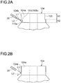
- FIGS. 2A and 2B are schematic diagrams describing a detection operation that an optical sensor detects a sensor detection surface of the compressor wheel according to the present embodiment.
- a compressor wheel 100 according to the present embodiment is made of a light alloy such as aluminum, magnesium, or titanium that is machined by casting, forging, shaving, or the like. As illustrated in FIGS. 1A to 1C , the compressor wheel 100 includes a disc-shaped rear plate portion 102, a boss portion 104 integrated with and disposed perpendicular to the rear plate portion 102, compressor blades 106 and 108 integrated with and disposed between the boss portion 104 and the rear plate portion 102, and a sensor detection portion 110. According to the present embodiment, a balance cut portion 105 is a part of a circumferential surface 104b of the tip end portion 104a of the boss portion 104. When the rotational unbalance of the compressor wheel is corrected, the balance cut portion 105 is cut.
- a balance cut portion 105 is a part of a circumferential surface 104b of the tip end portion 104a of the boss portion 104.
- the rear plate portion 102 is disposed on an opposite side of the tip end portion 104a disposed on one end side of the boss portion 104.
- the rear plate portion 102 extends in a vertical direction of a rotation shaft 52 (refer to FIG. 8 ) mounted on the boss portion 104, the vertical direction having an error of around ⁇ 5°.
- the compressor blades include six long blades 106 and six short blades 108 arranged alternately.
- a circular through-hole 103 is formed in the boss portion 104 and the rear plate portion 102.
- a thick portion 109 is disposed on a rear side of the rear plate portion 102 as a base of the boss portion 104, a stress concentrating at the base.
- the number of the compressor blades 106 and 108 is not limited to the foregoing number. Such a thick portion may not be disposed on the rear side of the rear plate portion 102.
- the sensor detection surface 110 that an optical sensor detects with reflected light of irradiation light is disposed on the circumferential surface 104b of the tip end portion 104a of the boss portion 104 so that the sensor detection surface 110 is inclined to the circumferential surface 104b.
- a bottom surface 110b of a hole portion 110a is formed in the boss portion 104b so that the bottom surface 110b is inclined to the circumferential surface 104b.
- the bottom surface 110b becomes the sensor detection surface 110.
- the sensor detection surface 110 is vertically inclined to the circumferential surface 104b.
- the sensor detection surface 110 is formed in a region A2 closer to the rear plate side than a region A1 on which the balance cut portion 105 is disposed.
- the hole portion 110a that becomes the sensor detection surface 110 that the optical sensor detects with light is formed between the balance cut portion 105 of the tip end portion 104a of the boss portion 104 that becomes a nut tightening portion of the compressor wheel 100 and the compressor blades 106 and 108.
- the sensor detection surface 110 is desirably as small as possible.
- the sensor detection surface 110 has a width enough to allow an optical sensor 30 to detect the sensor detection surface 110, for example approximately 0.5 mm to approximately 1.5 mm, desirably approximately 1 mm.
- the sensor detection surface 110 has an inclined angle enough to allow the optical sensor 30 to distinguish and detect the sensor detection surface 110 from the circumferential surface 104b of the tip end portion 104a of the boss portion 104 and the balance cut portion 105 that is shaved and machined to correct the rotational unbalance of the compressor wheel 100, for example approximately 30° to approximately 60°, desirably approximately 45°.
- the optical sensor 30 detects the sensor detection surface 110 with reflected light L 2 of irradiation light L1 with which the optical sensor 30 irradiates the sensor detection surface 110.
- the optical sensor 30 is a fiber sensor or the like that coaxially exits and enters light. As illustrated in FIG. 2A , the optical sensor 30 is inclined by approximately 45° to an axial direction of the boss portion 104. In other words, the optical sensor 30 is nearly perpendicular to the sensor detection surface 100, namely the bottom surface 110b of the hole portion 110a. In addition, the optical sensor 30 is inclined by approximately 45° to a circumferential surface 102a and a rear surface 102b of the rear plate portion 102 of the compressor wheel 100.
- the irradiation light L1 of the optical sensor 30 is regularly reflected on the sensor detection surface 110.
- the reflected light L2 enters the optical sensor 30.
- the optical sensor 30 detects the sensor detection surface 110 with the reflected light L2 of the irradiation light L1 with which the optical sensor 30 irradiates the sensor detection surface 110.
- the reflected light L1 does not enter the optical sensor 30.
- the hole portion 110a is formed in the boss portion 104 so that the hole portion is inclined to the circumferential surface 104b.
- FIGS. 3A and 3B are schematic diagrams describing a structure of a sensor detection surface of the compressor wheel according to the second embodiment of the present invention and a detection operation that an optical sensor detects the sensor detection surface.
- a tip end portion of a boss portion 204 has a first tip end portion 204a, on which a balance cut portion 205 is disposed, and a second tip end portion 206, disposed on a base end portion side of the first tip end portion 204a, the second tip end portion 206 having an outer diameter greater than the first tip end portion 204a.
- a slope surface 210b of a cut portion 210a is formed on a vertex side of a circumferential surface 206a of the second tip end portion 206 so that the slope surface 210b is inclined to the circumferential surface 206a.
- the slope surface 210b becomes a sensor detection surface 210.
- the sensor detection surface 210 is vertically inclined to the circumferential surface 206a of the second tip end portion 206. Since the other structural elements of the compressor wheel 200 according to the present embodiment are the same as those according to the first embodiment, their description will be omitted.
- the sensor detection surface 210 is disposed on a region A2 closer to a rear plate portion side than a region A1 on which the balance cut portion 205 is disposed.
- the slope surface 210b that becomes the sensor detection surface 210 is formed between the balance cut portion 205 of the first tip end portion 204a of the boss portion 204 that becomes a nut tightening portion of the compressor wheel 200 and the compressor blades 106 and 108 (refer to FIGS. 1A to 1C ).
- the sensor detection surface 210 is desirably as small as possible.
- the sensor detection surface 210 has a width enough to allow an optical sensor 30 to detect the sensor detection surface 210, for example approximately 0.5 mm to approximately 1.5 mm, desirably approximately 1 mm.
- the sensor detection surface 210 has an inclined angle enough to allow the optical sensor 30 to distinguish and detect the sensor detection surface 210 from the circumferential surface 204b of the first tip end portion 204a of the boss portion 204, the circumferential surface 206a of the second tip end portion 206, and the balance cut portion 205 that is shaved and machined to correct the rotational unbalance of the compressor wheel 200, for example approximately 30° to approximately 60°, desirably approximately 45°.
- the optical sensor 30 detects the sensor detection surface 210 with reflected light L2 of irradiation light L1 with which the optical sensor 30 irradiates the sensor detection surface 210.
- the optical sensor 30 is a fiber sensor or the like that coaxially exits and enters light. As illustrated in FIG. 3A , the optical sensor 30 is inclined by approximately 45° to an axial direction of the boss portion 204. In other words, the optical sensor 30 is nearly perpendicular to the sensor detection surface 210, namely the slope surface 210b of the cut portion 210a. In addition, the optical sensor 30 is inclined by approximately 45° to a circumferential surface and a rear surface of the rear plate portion 202 of the compressor wheel 200.
- the irradiation light L1 of the optical sensor 30 is regularly reflected on the sensor detection surface 210.
- the reflected light L2 enters the optical sensor 30.
- the optical sensor 30 detects the sensor detection surface 210 with the reflected light L2 of the irradiation light L1 with which the optical sensor 30 irradiates the sensor detection surface 210.
- the reflected light L2 does not enter the optical sensor 30.
- the cut portion 210a is inclined to the circumferential surface 206a of the second tip end portion 206.
- the optical sensor 30 detects the reflected light L2 only when the sensor detection surface 210 of the compressor wheel 200 passes through the front of the optical sensor 30.
- the sensor detection surface 210 that becomes the reference direction and position in which a rotational unbalance position and a rotational unbalance amount of the compressor wheel 200 are contactlessly measured can be accurately detected.
- the tip end portion of the boss portion 204 is formed of step portions of the first tip end portion 204a and the second tip end portion 206, the sensor detection surface 210 can be more easily machined than the other structures.
- FIGS. 4A and 4B are schematic diagrams describing a structure of a sensor detection surface of the compressor wheel according to the third embodiment of the present invention and a detection operation that an optical sensor detects the sensor detection surface.
- FIGS. 5A and B are schematic diagrams describing members that form the sensor detection surface of the compressor wheel according to the third embodiment of the present invention.
- a sensor detection surface 310 is formed on a downstream side upper surface of a compressor wheel 300, namely on a circumferential surface 302a of a rear plate portion 302.
- a cut portion 310a is formed on a vertex side of the circumferential surface 302a of a region Y excluding a region X where a balance cut portion 305 is formed so that the cut portion 310a is inclined to the circumferential surface 302a.
- a slope surface 310b of the cut portion 310a becomes the sensor detection surface 310.
- the sensor detection surface 310 is vertically inclined to the circumferential surface 302a of the rear plate portion 302. Since the other structural elements of the compressor wheel 300 according to the present embodiment are the same as those according to the first embodiment, their description will be omitted.
- the sensor detection surface 310 is desirably as small as possible.
- the sensor detection surface 310 has a width enough to allow an optical sensor 30 to detect the sensor detection surface 310, for example approximately 0.5 mm to approximately 1.5 mm, desirably approximately 1 mm.
- the sensor detection surface 310 has an inclined angle enough to allow the optical sensor 30 to distinguish and detect the sensor detection surface 310 from the circumferential surface 302 of the rear plate portion 302, for example approximately 30° to approximately 60°, desirably approximately 45°.
- the optical sensor 30 detects the sensor detection surface 310 with reflected light L2 of irradiation light L1 with which the optical sensor 30 irradiates the sensor detection surface 310.
- the optical sensor 30 is vertically inclined by approximately 450 to the circumferential surface 302a of the rear plate portion 302.
- the optical sensor 30 is nearly perpendicular to the sensor detection surface 310, namely the slope surface 310b of the cut portion 310a.
- the optical sensor 30 is inclined by approximately 45° to the circumferential surface 302a and the rear surface 302b of the rear plate portion 302 of the compressor wheel 300.
- the irradiation light L1 of the optical sensor 30 is regularly reflected on the sensor detection surface 310.
- the reflected light L2 enters the optical sensor 30.
- the optical sensor 30 detects the sensor detection surface 310 with the reflected light L2 of the irradiation light L1 with which the optical sensor 30 irradiates the sensor detection surface 310.
- the reflected light L2 does not enter the optical sensor 30.
- the cut portion 310a is formed on the circumferential surface 302a of the rear plate portion 302 so that the cut portion 310a is inclined to the circumferential surface 302a.
- the optical sensor 30 detects the reflected light L2 only when the sensor detection surface 310 of the compressor wheel 300 passes through the front of the optical sensor 30. Consequently, when the rotational unbalance of a compressor assembly 50 (refer to FIG. 8 ) on which the compressor wheel 300 is disposed is corrected, the sensor detection surface 310 that becomes the reference direction and position in which a rotational unbalance position and a rotational unbalance amount of the compressor wheel 300 are contactlessly measured can be accurately detected.
- the cut portion 310a is formed on the circumferential surface 302a of the rear plate portion 302 that does not interfere with the compressor blades 306 and 308, the sensor detection surface 310 can be easily machined.
- FIGS. 6A and 6B are schematic diagrams describing a structure of a sensor detection surface of the compressor wheel according to the fourth embodiment of the present invention and a detection operation that an optical sensor detects the sensor detection surface.
- a sensor detection surface 410 is formed on a circumferential surface 404b of a tip end portion 404 of a boss portion 404 so that the sensor detection surface 410 is inclined to the circumferential surface 404b.
- a slope surface 410b of a cut portion 410a is horizontally inclined to the circumferential surface 404b of the boss portion 404.
- the slope surface 410b becomes the sensor detection surface 410.
- the sensor detection surface 410 is horizontally inclined to the circumferential surface 404b. Since the other structural elements of the compressor wheel 400 according to the present embodiment are the same as those according to the first embodiment, their description will be omitted.
- the sensor detection surface 410 is desirably as small as possible.
- the sensor detection surface 410 has a width enough to allow an optical sensor 30 to detect the sensor detection surface 410, for example approximately 0.5 mm to approximately 1.5 mm, desirably approximately 1 mm.
- the sensor detection surface 410 has an inclined angle enough to allow the optical sensor 30 to distinguish and detect the sensor detection surface 410 from the circumferential surface 404b of the tip end portion 404a of the boss portion 404 and a balance cut portion 405 that is shaved and machined to correct the rotational unbalance of the compressor wheel 400, for example approximately 300 to approximately 60°, desirably approximately 45°.
- the optical sensor 30 detects the sensor detection surface 410 with reflected light L2 of irradiation light L1 with which the optical sensor 30 irradiates the sensor detection surface 410.
- the optical sensor 30 is a fiber sensor or the like that coaxially exits and enters light. As illustrated in FIG. 6A , the optical sensor 30 is horizontally inclined by approximately 45° to the boss portion 404. In other words, the optical sensor 30 is nearly perpendicular to the sensor detection surface 100, namely the slope surface 410b of the cut portion 410a.
- the irradiation light L1 of the optical sensor 30 is regularly reflected on the sensor detection surface 410.
- the reflected light L2 enters the optical sensor 30.
- the optical sensor 30 detects the sensor detection surface 410 with the reflected light L2 of the irradiation light L1 with which the optical sensor 30 irradiates the sensor detection surface 410.
- the reflected light L2 does not enter the optical sensor 30.
- the cut portion 410a is formed in the tip end portion 404b of the boss portion 404 so that the cut portion 410a is inclined to the circumferential surface 404b.
- FIGS. 7A and 7B are schematic diagrams describing a structure of a sensor detection surface of the compressor wheel according to the fifth embodiment of the present invention and a detection operation that an optical sensor detects the sensor detection surface.
- a sensor detection surface 510 is formed on a balance cut portion 505 of a tip end portion 504a of a boss portion 504. As illustrated in FIG. 7A , a bottom surface 510b of a hole portion 510a is formed in a balance cut portion 505 of a boss portion 504 so that the bottom surface 510b is inclined to the circumferential surface 504b of the balance cut portion 505. The bottom surface 510b becomes the sensor detection surface 510. In other words, according to the present embodiment, the sensor detection surface 510 is vertically inclined to the circumferential surface 504b. Since the other structural elements of the compressor wheel 500 according to the present embodiment are the same as those according to the first embodiment, their description will be omitted.
- the sensor detection surface 510 is desirably as small as possible.
- the sensor detection surface 510 has a width enough to allow an optical sensor 30 to detect the sensor detection surface 510, for example approximately 0.5 mm to approximately 1.5 mm, desirably approximately 1 mm.
- the sensor detection surface 510 has an inclined angle enough to allow the optical sensor 30 to distinguish and detect the sensor detection surface 510 from the circumferential surface 504b of the tip end portion 504a of the boss portion 504 and the balance cut portion 505 that is shaved and machined to correct the rotational unbalance of the compressor wheel 500, for example approximately 300 to approximately 60°, desirably approximately 45°.
- the optical sensor 30 detects the sensor detection surface 510 with reflected light L2 of irradiation light L1 with which the optical sensor 30 irradiates the sensor detection surface 510.
- the optical sensor 30 is a fiber sensor or the like that coaxially exits and enters light. As illustrated in FIG. 7A , the optical sensor 30 is vertically inclined by approximately 45° to the boss portion 504. In other words, the optical sensor 30 is nearly perpendicular to the sensor detection surface 500, namely the bottom surface 510b of the hole portion 510a.
- the irradiation light L1 of the optical sensor 30 is regularly reflected on the sensor detection surface 510.
- the reflected light L2 enters the optical sensor 30.
- the optical sensor 30 detects the sensor detection surface 510 with the reflected light L2 of the irradiation light L1 with which the optical sensor 30 irradiates the sensor detection surface 510.
- the reflected light L2 does not enter the optical sensor 30.
- the hole portion 510a is inclined to the circumferential surface 504b of the tip end portion 504a of the boss portion 504.
- the bottom surface 510b of the hole portion 510a is closer to a rotation axis A5 side of the compressor wheel 500 than a maximum cut range of the balance cut portion 505.
- a depth D1 of the hole portion 510a in which the sensor detection surface 510 is formed is greater than a depth D2 of the balance cut portion 505, the sensor detection surface 510 can be formed in the balance cut portion 505 so that the sensor detection surface 510 overlaps with the balance cut portion 505.
- a length of the tip end portion 504a of the boss portion 504 of the compressor wheel 500 according to the present embodiment becomes shorter than that of the compressor wheel according to each of the first to fourth embodiments, the compressor wheel 500 can be compacted.
- the compressor wheel according to each of the embodiments of the present invention has a sensor detection surface at any portion other than its rear surface as a mark not necessary to be removed after the rotational unbalance of the compressor wheel is corrected. Since reference direction and position are detected based on the sensor detection surface, after a cartridge type compressor assembly is assembled, when the rotational unbalance of the compressor assembly is detected, the sensor detection surface as the reference detection portion is not hidden. As a result, after the compressor assembly is assembled, the rotational unbalance of the compressor assembly can be easily detected. In addition, since the sensor detection surface can be easily formed on the compressor wheel in advance, after the compressor assembly is assembled, the rotation unbalance of the compressor assembly can be detected without need to use a new tool such as a magnetized nut. Thus, the process for detecting the rotational unbalance of the compressor assembly can be shortened.
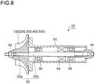
- FIG. 8 is a schematic diagram illustrating an outlined structure of a compressor assembly on which a compressor wheel according to each of the embodiments of the present invention is disposed.
- the compressor assembly 50 includes a rotation shaft 52, a rotor core 54 mounted on one end side of the rotation shaft 52, a compressor wheel 100 (200, 300, 400, 500) according to each of the embodiments, the compressor wheel being mounted on another end side of the rotation shaft 52, and bearings 56, 58 that support the rotation shaft 52.
- the rotation shaft 52, the rotor core 54, and the bearings 56 and 58 are enclosed in a casing 60, a part of the rotation shaft 52 on which the compressor wheel 100 (200, 300, 400, 500) is disposed being exposed to the outside. Both end portions of the rotation shaft 52 extending from both end sides of the compressor assembly 50 are tightened by nuts 62 and 64.
- the rotation shaft 52 is composed of a thick shaft portion 52b formed at a middle portion and in an axial direction of the compressor assembly 50 and a thin shaft portion 52a formed on one end side of the compressor assembly 50 and enclosed by the compressor wheel 100 (200, 300, 400, 500).
- a coupling portion of the thick shaft portion 52b and the thin shaft portion 52a is stepped so that when the compressor wheel 100 (200, 300, 400, 500) is mounted on the compressor assembly 50, the coupling portion functions as a stopper in the axial direction of the compressor assembly 50.
- the nuts 62 and 64 are mounted on both end sides of the rotation shaft 52. After the compressor assembly 50 is assembled, the nuts 62 and 64 are used to adjust the rotational balance of the compressor assembly 50.
- the bearings 56 and 58 may be ball bearings (angular contact ball bearings) or metal bearings (slide bearings), but not limited thereto. Moreover, according to the present embodiment, as illustrated in FIG. 8 , the bearings 56 and 58 are secured to both sides of the rotor core 54 disposed on the rotation shaft 52. Alternatively, the rotor core 54 and the bearings 56 and 58 may be disposed at other positions not illustrated in FIG. 8 .
- FIG. 9 is a schematic diagram illustrating an outlined structure of a rotational unbalance detection device for a compressor assembly according to an embodiment of the present invention, a compressor wheel according to each of the embodiments of the present invention being disposed on the compressor assembly.
- an optical sensor 30a or 30b detects a sensor detection surface formed on a compressor wheel 100 (200, 300, 400, 500) disposed on the compressor assembly 50.
- the rotational unbalance detection device 10 measures a rotational unbalance position and a rotational unbalance amount of the compressor wheel 100 (200, 300, 400, 500) based on the sensor detection surface.
- the rotational unbalance detection device 10 includes an air supply unit 12, a compressor cover 14 that intakes air, a detection portion 31 provided with the optical sensor 30a or 30b, a retainer 16 that retains the compressor assembly 50, an acceleration detector (not illustrated), a vector filter (not illustrated) connected to the optical sensor 30a or 30b and the acceleration detector, an A/D converter (not shown) connected to the vector filter, and a computer (not illustrated) connected to the A/D converter.
- an open portion 18 is formed on another end portion of the compressor assembly 50, the other end portion being opposite to one end portion thereof on which the compressor wheel is disposed.
- the nut 64 or the like (refer to FIG. 8 ) can be shaved from the rear end side of the compressor assembly 50. Since the open portion 18 is formed on the rear end side of the compressor assembly 50, not only the nut 62 disposed on the front end side of the compressor assembly 50, but the nut 64 disposed on the rear end side can be shaved. As a result, the rotational unbalance of the compressor assembly can be more appropriately adjusted than the other structures.
- the air supply unit 12 functions as a rotation portion that supplies air to compressor blades of the compressor wheel 100 (200, 300, 400, 500) through the compressor cover 14 and rotates the compressor wheel.
- the rotational unbalance of the compressor assembly from which a motor and an inverter are disconnected can be easily corrected.
- the rotational unbalance detection device 10 can be simplified and compacted.
- the air supply unit 12 desirably supplies air from the downstream side of the compressor wheel 100 (200, 300, 400, 500) to the upstream side thereof so as to effectively direct supplied air to the compressor wheel.
- the air supply unit 12 desirably supplies air from the upstream side of the compressor wheel 100 (200, 300, 400, 500) to the downstream side thereof so as to equally and radially direct energy of supplied air to the compressor wheel.
- the detection portion 31 is provided with the optical sensor 30a or 30b that detects the sensor detection surface formed on the compressor wheel 100 (200, 300, 400, 500).
- the first optical sensor 30a that can irradiate the tip end portion side of the boss portion with light is used.
- the second optical sensor 30b that can irradiate the vertex side of the circumferential surface of the rear plate portion with light is used.
- the rotational unbalance detection device 10 when the compressor wheel 100 (200, 300, 400, 500) is rotated and is irradiated by the optical sensor 30a or 30b, detection signals are input from the optical sensor 30a or 30b and the acceleration detector to the computer through the vector filter and the A/D converter.
- the computer calculates vibration characteristics, calibration, and balance, statistically processes these data, and records them. Thereafter, the rotational unbalance detection device 10 measures rotational unbalance angles and rotational unbalance amounts of the compressor wheel 100 (200, 300, 400, 500) based on the sensor detection surface 110 as 0 point using vector calculations and vector decompositions.
- FIG. 10 is a flow chart describing the rotational unbalance correction operation of the rotational unbalance detection device for the compressor assembly according to the present embodiment.
- an assembled compressor assembly is mounted on a rotational unbalance detection device (in step S10). Thereafter, a compressor wheel is rotated at a target rotation speed. Thereafter, rotational unbalance vectors on both sides of the compressor wheel are measured so as to calculate rotational unbalance correction amounts (in step S11).
- the compressor wheel is rotated by compressed air supplied from an air supply unit. Rotational unbalance positions and rotational unbalance amounts of the compressor wheel are calculated based on the detection result of an optical sensor.
- a nut disposed on one end side of the compressor wheel or a nut disposed on another side of the compressor wheel is shaved by a shaving unit or the like for an amount necessary to correct the rotational unbalance of the compressor wheel based on the calculated rotational unbalance positions and rotational unbalance amounts (in step S12).
- the nut is debured (in step S13).
- it is determined whether or not vibrations generated in the rotating compressor wheel are acceptable (in step S14).
- the vibrations generated in the rotating compressor wheel are acceptable, the rotational unbalance correction operation for the compressor assembly on which the compressor wheel is disposed is completed.
- the nut that has been shaved is replaced with a good one (in step S15). Thereafter, the operation is repeated from step S1.
- the reference direction and position based on which the rotational unbalance of the compressor assembly is measured can be accurately detected.
- the rotational unbalance of the compressor assembly since the compressor wheel is rotated by an air supply unit, the rotational unbalance of the compressor assembly from which the motor of the electric compressor and the inverter are disconnected can be easily corrected. As a result, the rotational unbalance detection device can be simplified and compacted.
- FIG. 11 is a schematic diagram illustrating an outlined structure of a rotational unbalance detection device according to another embodiment of the present invention.
- a rotational unbalance detection device 20 includes a detection portion 31 provided with an optical sensor 30a or 30b, a motor 22 that rotationally drives a rotation shaft mounted on a compressor assembly 50, an acceleration detector (not illustrated), a vector filter (not illustrated) connected to the optical sensor 30a or 30b and the acceleration detector, an A/D converter (not illustrated) connected to the vector filter, and a computer (not illustrated) connected to the A/D converter.
- the motor 22 functions as a rotation portion that rotates the compressor wheel 100 (200, 300, 400, 500) of the compressor assembly 50.
- the detection portion 31 is provided with the optical sensor 30a or 30b that detects a sensor detection surface of the compressor wheel 100 (200, 300, 400, 500).
- the first optical sensor 30a that irradiates the tip end portion side with light is used.
- the second optical sensor 30b that irradiates the vertex side of the circumferential surface of the rear panel portion with light is used.
- the periphery of the compressor wheel 100 (200, 300, 400, 500) is surrounded by a compressor cover 24 provided with the optical sensor 30a or 30b.
- a compressor cover 24 provided with the optical sensor 30a or 30b.
- only an optical sensor may be approached to the compressor wheel that is not covered with the compressor cover 24.
- the compressor wheel is desirably covered with the compressor cover 24.
- the rotation shaft mounted on the compressor assembly is rotationally driven with a current that flows in the motor 22.
- the rotational unbalance of the compressor wheel can be corrected by magnetic attraction of the motor.
- the quality of the final product can be improved.
- the discharge pressure, electricity conduction, responsiveness, and so forth can be measured along with the rotational unbalance.
- the final production can be verified.
- a word described at least once along with a broad or synonymous word can be replaced with such a broad or synonymous word in any place of the specification and drawings.
- the structures and operations of the compressor wheel and the rotational unbalance detection device for the compressor assembly are not limited to those described in the individual embodiments of the present invention and can include various modifications.
Landscapes
- Engineering & Computer Science (AREA)
- Mechanical Engineering (AREA)
- General Engineering & Computer Science (AREA)
- Chemical & Material Sciences (AREA)
- Combustion & Propulsion (AREA)
- Physics & Mathematics (AREA)
- General Physics & Mathematics (AREA)
- Testing Of Balance (AREA)
- Structures Of Non-Positive Displacement Pumps (AREA)
- Supercharger (AREA)
Claims (8)
- Eine Kompressoranordnung (50) aufweisend:eine Drehwelle (52);einen Rotorkern (54), welcher an einer End-Seite der Drehwelle (52) befestigt ist;ein Verdichtungsrad (100; 200; 300; 400; 500), welches an einer anderen Endseite der Drehwelle (52) befestigt ist;Lagerungen (56, 58), welche die Drehwelle (52) stützen; undein Gehäuse (60), welches einen Teil der Drehwelle (52) des Rotorkerns (54) und der Lagerungen (56, 58) umschließt, wobei das Verdichtungsrad (100) umfasst:einen Nabenteil (104), welcher an einer Drehwelle (52) befestigt ist;einen Rückplattenteil (102; 302), welcher an einer gegenüberliegenden Seite eines Kopfendenteils (104a) angeordnet ist, welcher an einer Endseite des Nabenteils (104) angeordnet ist, wobei der Rückplattenteil (102) sich senkrecht zu einer axialen Richtung der Drehwelle (52) erstreckt; undeine Sensorerkennungsoberfläche (110; 310), welche an einer umfänglichen Oberfläche (104b) des Kopfendteils (104a) des Nabenteils (104) oder an einer Eckseite einer umfänglichen Oberfläche (302a) des Rückplattenteils (302) ausgebildet ist, wobei die Sensorerkennungsoberfläche (110; 310) geneigt ist zur umfänglichen Oberfläche (104b) des Endteils (104a) oder der umfänglichen Oberfläche (302a) des Rückplattenteils (302), wobei die Sensorerkennungsoberfläche (110; 310) durch einen optischen Sensor (30) detektierbar ist, welcher die Sensorerkennungsoberfläche (110; 310) mit Licht (L1) bestrahlt und Licht (L2), welches davon reflektiert wurde, detektiert; undein Ausgleichseinschnittteil (105; 305), welcher an der umfänglichen Oberfläche (104b) des Kopfendteils (104a) des Nabenteils (104) oder an der umfänglichen Oberfläche (302a) des Rückplattenteils (302) angeordnet ist, wobei der Ausgleichseinschnittteil (105; 305) Teil einer umfänglichen Oberfläche (104b; 302a) ist, welche eingeschnitten ist, undwobei die Sensorerkennungsoberfläche (110; 310) einen Neigungswinkel aufweist, der eingerichtet ist, um es einem optischen Sensor (30) zu erlauben, die Sensorerkennungsoberfläche (110; 310) des Ausgleichseinschnittteils (105; 305) zu unterscheiden und zu detektieren.
- Kompressoranordnung (50) gemäß Anspruch 1,
wobei der Ausgleichseinschnittteil (105; 305) an der umfänglichen Oberfläche (104b) des Kopfendteils (104a) des Nabenteils (104) angeordnet ist; und
wobei die Sensorerkennungsoberfläche (110) näher ausgebildet ist zu dem Rückplattenteil (102) als zu einem Bereich, wo der Ausgleichseinschnittteil (105) angeordnet ist, und näher ausgebildet ist zu dem Kopfendteil (104a) als zu einer Rückseitenfläche (102b) des Rückplattenteils (102). - Kompressorzusammenbau (50) gemäß Anspruch 2,
wobei die Sensorerkennungsoberfläche (110) eine untere Oberfläche (110b) eines Lochteils (110a) ist, welcher in dem Nabenteil (105) ausgebildet ist, wobei die Sensorerkennungsoberfläche (110) zu der umfänglichen Oberfläche (104b) des Nabenteils (104) geneigt ist. - Kompressoranordnung (50) gemäß Anspruch 2,
wobei der Kopfendteil einen ersten Kopfendteil (204a) umfasst, an welchem der Ausgleichseinschnittteil (205) angeordnet ist, und einen zweiten Kopfendteil (206), welcher an einer Basisendseite des ersten Kopfendteils (204a) ausgebildet ist, wobei der zweite Kopfendteil (206) einen äußeren Durchmesser aufweist, welcher größer ist als der erste Kopfendteil (204a), und
wobei die Sensorerkennungsoberfläche (210) eine geneigte Oberfläche (210b) eines Ausschnittteils (210a) ist, welche an einer Eckseite der umfänglichen Oberfläche (206a) des zweiten Kopfendteils (206) ausgebildet ist, wobei die Sensorerkennungsoberfläche (210) zu der umfänglichen Oberfläche (206a) des zweiten Kopfendteils (206) geneigt ist. - Kompressoranordnung (50) gemäß Anspruch 1,
wobei die Sensorerkennungsoberfläche (310) eine geneigte Oberfläche (310b) eines Ausschnittteils (310a) ist, welcher an einer Eckseite der umfänglichen Oberfläche (302a) des Rückplattenteils (302) ausgebildet ist, wobei die Sensorerkennungsoberfläche (310) zu der umfänglichen Oberfläche (302a) des Rückplattenteils (302) geneigt ist. - Kompressoranordnung (50) gemäß Anspruch 5,
wobei der Ausgleichseinschnittteil (305) an der umfänglichen Oberfläche (302a) des Rückplattenteils (302) angeordnet ist, und
wobei die Sensorerkennungsoberfläche (310) an einer Eckseite der umfänglichen Oberfläche (302a) des Rückplattenteils (302) angeordnet ist, so dass die Sensorerkennungsoberfläche (310) nicht mit dem Ausgleichseinschnittteil (305) störend eingreift. - Die Kompressoranordnung (50) gemäß Anspruch 2,
wobei die Sensorerkennungsoberfläche (410) eine geneigte Oberfläche (410b) eines Ausschnittteils (410a) ist, welcher an der umfänglichen Oberfläche (404b) des Nabenteils (404) ausgebildet ist, wobei die geneigte Oberfläche (410b) zu der umfänglichen Oberfläche (404b) geneigt ist. - Kompressoranordnung (50) gemäß Anspruch 1,
wobei der Ausgleichseinschnittteil (505) an der umfänglichen Oberfläche (504b) des Kopfendteils des Nabenteils (504) angeordnet ist, und
wobei die Sensorerkennungsoberfläche (510) eine untere Oberfläche (510b) eines Lochteils (510a) ist, welcher in einem Bereich ausgebildet ist, wo der Ausgleichseinschnittteil (505) angeordnet ist, wobei die Sensorerkennungsoberfläche (510) zu der Ausschnittsoberfläche (505a) des Ausgleichseinschnittteils (505) geneigt ist, wobei die untere Oberfläche (510b) näher zu einer Seite einer Drehachse (A5) des Verdichtungsrads (500) ist als zu einem maximalen Einschnittsbereich des Ausgleichseinschnittteils (505).
Applications Claiming Priority (1)
| Application Number | Priority Date | Filing Date | Title |
|---|---|---|---|
| PCT/JP2013/054562 WO2014128927A1 (ja) | 2013-02-22 | 2013-02-22 | コンプレッサホイール、及びコンプレッサアセンブリのアンバランス検出装置 |
Publications (3)
| Publication Number | Publication Date |
|---|---|
| EP2960465A1 EP2960465A1 (de) | 2015-12-30 |
| EP2960465A4 EP2960465A4 (de) | 2016-01-13 |
| EP2960465B1 true EP2960465B1 (de) | 2017-05-10 |
Family
ID=51390752
Family Applications (1)
| Application Number | Title | Priority Date | Filing Date |
|---|---|---|---|
| EP13875952.7A Active EP2960465B1 (de) | 2013-02-22 | 2013-02-22 | Verdichteranordnung |
Country Status (5)
| Country | Link |
|---|---|
| US (1) | US9897107B2 (de) |
| EP (1) | EP2960465B1 (de) |
| JP (1) | JP5588085B1 (de) |
| CN (1) | CN104870779B (de) |
| WO (1) | WO2014128927A1 (de) |
Families Citing this family (14)
| Publication number | Priority date | Publication date | Assignee | Title |
|---|---|---|---|---|
| FR2944060B1 (fr) * | 2009-04-06 | 2013-07-19 | Turbomeca | Systeme d'air secondaire pour compresseur centrifuge ou mixte |
| JP1523931S (de) * | 2014-12-19 | 2015-05-18 | ||
| JP6011666B2 (ja) * | 2015-03-19 | 2016-10-19 | 株式会社豊田自動織機 | 回転体 |
| WO2016182688A1 (en) * | 2015-05-08 | 2016-11-17 | Balance Technology, Inc. | Abrasive water jet balancing appartus and method for rotating components |
| EP3447264B1 (de) * | 2016-05-26 | 2020-07-08 | Mitsubishi Heavy Industries Engine & Turbocharger, Ltd. | Vorrichtung und verfahren zur ungleichgewichtserkennung |
| WO2017203648A1 (ja) | 2016-05-26 | 2017-11-30 | 三菱重工業株式会社 | アンバランス検出装置、および、アンバランス検出方法 |
| WO2018037441A1 (ja) * | 2016-08-22 | 2018-03-01 | 三菱重工業株式会社 | 斜流式タービンホイール |
| JP6593543B2 (ja) | 2016-09-02 | 2019-10-23 | 株式会社Ihi | 過給機用インペラ |
| JP6831225B2 (ja) | 2016-12-07 | 2021-02-17 | 三菱重工エンジン&ターボチャージャ株式会社 | 振動絶縁部材、および振動絶縁部材を備えるアンバランス検出装置 |
| US9957981B1 (en) * | 2017-04-13 | 2018-05-01 | Borgwarner Inc. | Turbocharger having compressor portion with imbalance correction region |
| FR3086754B1 (fr) * | 2018-10-02 | 2021-11-12 | Datatechnic Sas | Procede d'equilibrage du balourd d'un ensemble arbre-roue |
| US11619239B2 (en) * | 2020-11-12 | 2023-04-04 | Air-Tec Innovations, LLC | Turbo charger with compressor wheel |
| CN113280469B (zh) * | 2021-06-01 | 2022-05-06 | 珠海拓芯科技有限公司 | 一种风机风叶故障检测方法、空调、计算机可读存储介质 |
| US11971053B2 (en) * | 2021-10-13 | 2024-04-30 | Garrett Transportation I Inc | Rotor with balancing features and balancing method |
Family Cites Families (16)
| Publication number | Priority date | Publication date | Assignee | Title |
|---|---|---|---|---|
| DE2217264C2 (de) * | 1972-04-11 | 1974-05-16 | Carl Schenck Maschinenfabrik Gmbh, 6100 Darmstadt | Auswuchtmaschine mit einer Einrichtung zur Bestimmung und optischen Anzeige einer Unwucht |
| JPS61104349U (de) * | 1984-12-13 | 1986-07-02 | ||
| JPH0323320A (ja) * | 1989-06-20 | 1991-01-31 | Mitsubishi Motors Corp | ターボチャージャ付き内燃機関の自己診断装置 |
| JPH04315936A (ja) * | 1991-04-15 | 1992-11-06 | Nissan Motor Co Ltd | 回転体のアンバランス量測定装置 |
| US5353640A (en) * | 1993-05-03 | 1994-10-11 | Industrial Technology Research Institute | Air-jet driven dynamic balance test apparatus |
| IT1285484B1 (it) * | 1996-10-08 | 1998-06-08 | Balance Systems Srl | Dispositivo di equilibratura di un rotore mediante asportazione di materiale |
| JPH10299501A (ja) | 1997-04-28 | 1998-11-10 | Toyota Motor Corp | ターボチャージャの製造方法と製造装置 |
| JP2003302304A (ja) * | 2002-04-09 | 2003-10-24 | Mitsubishi Heavy Ind Ltd | 回転体ワークのバランス修正方法、バランス修正装置および回転ワークの製造方法 |
| JP2006214884A (ja) * | 2005-02-03 | 2006-08-17 | Denso Corp | バランス修正装置およびバランス修正方法 |
| JP4662155B2 (ja) | 2006-01-10 | 2011-03-30 | 株式会社Ihi | 電動機付過給機の回転バランス修正方法および回転バランス試験装置 |
| JP4618142B2 (ja) * | 2006-01-20 | 2011-01-26 | トヨタ自動車株式会社 | ターボチャージャ |
| JP4710736B2 (ja) | 2006-06-23 | 2011-06-29 | トヨタ自動車株式会社 | 電動過給機のバランス修正装置およびバランス修正方法 |
| JP4807185B2 (ja) | 2006-08-29 | 2011-11-02 | 株式会社Ihi | 回転体のバランス修正方法及び装置 |
| JP2010096036A (ja) * | 2008-10-14 | 2010-04-30 | Toyota Motor Corp | ターボチャージャのアンバランス修正方法 |
| DE112010001369T5 (de) | 2009-03-25 | 2012-05-16 | Borgwarner Inc. | Reduzieren von turboladerkernunwucht mit zentriervorrichtung |
| JP2010275878A (ja) | 2009-05-26 | 2010-12-09 | Ihi Corp | インペラ、過給機、及びインペラの製造方法 |
-
2013
- 2013-02-22 EP EP13875952.7A patent/EP2960465B1/de active Active
- 2013-02-22 US US14/759,566 patent/US9897107B2/en active Active
- 2013-02-22 JP JP2014501357A patent/JP5588085B1/ja active Active
- 2013-02-22 CN CN201380066536.7A patent/CN104870779B/zh active Active
- 2013-02-22 WO PCT/JP2013/054562 patent/WO2014128927A1/ja active Application Filing
Also Published As
| Publication number | Publication date |
|---|---|
| CN104870779B (zh) | 2018-01-19 |
| JP5588085B1 (ja) | 2014-09-10 |
| JPWO2014128927A1 (ja) | 2017-02-02 |
| WO2014128927A1 (ja) | 2014-08-28 |
| CN104870779A (zh) | 2015-08-26 |
| EP2960465A4 (de) | 2016-01-13 |
| US20150361993A1 (en) | 2015-12-17 |
| EP2960465A1 (de) | 2015-12-30 |
| US9897107B2 (en) | 2018-02-20 |
Similar Documents
| Publication | Publication Date | Title |
|---|---|---|
| EP2960465B1 (de) | Verdichteranordnung | |
| EP1971761B1 (de) | Verfahren und vorrichtung zum auswuchten eines elektrisch unterstützten turbolader-rotors | |
| US20200182252A1 (en) | Rotation driving device, method for mounting rotation driving device, axial blower, method for mounting axial blower, and laser oscillator | |
| US9874100B2 (en) | Turbine rotor and turbocharger having the turbine rotor | |
| BRPI0617745A2 (pt) | processo e dispositivo para a medição dinámica do desquilìbrio de um rotor | |
| CN103884504A (zh) | 一种弹性箔片动压气体推力轴承受轴向力测试结构 | |
| JP5212789B2 (ja) | 回転体のアンバランス修正方法及び装置 | |
| US11131596B2 (en) | Vibration detection device, and unbalance detection device including the vibration detection device | |
| JP2022151452A (ja) | 回転体のバランス測定装置とこのバランス測定方法 | |
| JPS62150133A (ja) | 翼の回転試験装置 | |
| JP5262392B2 (ja) | 回転機械支持装置及びその設計方法 | |
| JP5660292B2 (ja) | バランス修正装置と方法 | |
| JP6625209B2 (ja) | アンバランス検出装置、および、アンバランス検出方法 | |
| JP2010281743A (ja) | 影響係数取得方法 | |
| JP4559912B2 (ja) | 磁気軸受装置 | |
| JP4702203B2 (ja) | 電動過給機のバランス修正装置およびバランス修正方法 | |
| KR20150119873A (ko) | 출력 결정 방법 및 터보 기계 | |
| JP5353720B2 (ja) | 真空ポンプ | |
| JP5332241B2 (ja) | 回転機械支持装置 | |
| JP2014218903A (ja) | インペラの修正方法、過給機の修正方法及び過給機の修正装置 | |
| JP5891729B2 (ja) | 過給機 | |
| CN207610853U (zh) | 旋转机械偏摆量的测量装置 | |
| JP5605686B2 (ja) | 圧力調整機構と圧力調整方法 | |
| JP5553217B2 (ja) | バランサー | |
| CN113566666B (zh) | 低压涡轮转、静子轴向距离测量方法 |
Legal Events
| Date | Code | Title | Description |
|---|---|---|---|
| PUAI | Public reference made under article 153(3) epc to a published international application that has entered the european phase |
Free format text: ORIGINAL CODE: 0009012 |
|
| REG | Reference to a national code |
Ref country code: DE Ref legal event code: R079 Ref document number: 602013021116 Country of ref document: DE Free format text: PREVIOUS MAIN CLASS: F02B0039160000 Ipc: F04D0029280000 |
|
| 17P | Request for examination filed |
Effective date: 20150707 |
|
| AK | Designated contracting states |
Kind code of ref document: A1 Designated state(s): AL AT BE BG CH CY CZ DE DK EE ES FI FR GB GR HR HU IE IS IT LI LT LU LV MC MK MT NL NO PL PT RO RS SE SI SK SM TR |
|
| AX | Request for extension of the european patent |
Extension state: BA ME |
|
| A4 | Supplementary search report drawn up and despatched |
Effective date: 20151210 |
|
| RIC1 | Information provided on ipc code assigned before grant |
Ipc: F04D 29/66 20060101ALI20151204BHEP Ipc: F04D 29/28 20060101AFI20151204BHEP |
|
| DAX | Request for extension of the european patent (deleted) | ||
| GRAP | Despatch of communication of intention to grant a patent |
Free format text: ORIGINAL CODE: EPIDOSNIGR1 |
|
| INTG | Intention to grant announced |
Effective date: 20161213 |
|
| GRAS | Grant fee paid |
Free format text: ORIGINAL CODE: EPIDOSNIGR3 |
|
| GRAA | (expected) grant |
Free format text: ORIGINAL CODE: 0009210 |
|
| AK | Designated contracting states |
Kind code of ref document: B1 Designated state(s): AL AT BE BG CH CY CZ DE DK EE ES FI FR GB GR HR HU IE IS IT LI LT LU LV MC MK MT NL NO PL PT RO RS SE SI SK SM TR |
|
| REG | Reference to a national code |
Ref country code: GB Ref legal event code: FG4D |
|
| REG | Reference to a national code |
Ref country code: AT Ref legal event code: REF Ref document number: 892654 Country of ref document: AT Kind code of ref document: T Effective date: 20170515 Ref country code: CH Ref legal event code: EP |
|
| REG | Reference to a national code |
Ref country code: IE Ref legal event code: FG4D |
|
| REG | Reference to a national code |
Ref country code: DE Ref legal event code: R096 Ref document number: 602013021116 Country of ref document: DE |
|
| REG | Reference to a national code |
Ref country code: NL Ref legal event code: FP |
|
| REG | Reference to a national code |
Ref country code: LT Ref legal event code: MG4D |
|
| REG | Reference to a national code |
Ref country code: AT Ref legal event code: MK05 Ref document number: 892654 Country of ref document: AT Kind code of ref document: T Effective date: 20170510 |
|
| PG25 | Lapsed in a contracting state [announced via postgrant information from national office to epo] |
Ref country code: AT Free format text: LAPSE BECAUSE OF FAILURE TO SUBMIT A TRANSLATION OF THE DESCRIPTION OR TO PAY THE FEE WITHIN THE PRESCRIBED TIME-LIMIT Effective date: 20170510 Ref country code: ES Free format text: LAPSE BECAUSE OF FAILURE TO SUBMIT A TRANSLATION OF THE DESCRIPTION OR TO PAY THE FEE WITHIN THE PRESCRIBED TIME-LIMIT Effective date: 20170510 Ref country code: NO Free format text: LAPSE BECAUSE OF FAILURE TO SUBMIT A TRANSLATION OF THE DESCRIPTION OR TO PAY THE FEE WITHIN THE PRESCRIBED TIME-LIMIT Effective date: 20170810 Ref country code: GR Free format text: LAPSE BECAUSE OF FAILURE TO SUBMIT A TRANSLATION OF THE DESCRIPTION OR TO PAY THE FEE WITHIN THE PRESCRIBED TIME-LIMIT Effective date: 20170811 Ref country code: FI Free format text: LAPSE BECAUSE OF FAILURE TO SUBMIT A TRANSLATION OF THE DESCRIPTION OR TO PAY THE FEE WITHIN THE PRESCRIBED TIME-LIMIT Effective date: 20170510 Ref country code: LT Free format text: LAPSE BECAUSE OF FAILURE TO SUBMIT A TRANSLATION OF THE DESCRIPTION OR TO PAY THE FEE WITHIN THE PRESCRIBED TIME-LIMIT Effective date: 20170510 Ref country code: HR Free format text: LAPSE BECAUSE OF FAILURE TO SUBMIT A TRANSLATION OF THE DESCRIPTION OR TO PAY THE FEE WITHIN THE PRESCRIBED TIME-LIMIT Effective date: 20170510 |
|
| PG25 | Lapsed in a contracting state [announced via postgrant information from national office to epo] |
Ref country code: PL Free format text: LAPSE BECAUSE OF FAILURE TO SUBMIT A TRANSLATION OF THE DESCRIPTION OR TO PAY THE FEE WITHIN THE PRESCRIBED TIME-LIMIT Effective date: 20170510 Ref country code: BG Free format text: LAPSE BECAUSE OF FAILURE TO SUBMIT A TRANSLATION OF THE DESCRIPTION OR TO PAY THE FEE WITHIN THE PRESCRIBED TIME-LIMIT Effective date: 20170810 Ref country code: LV Free format text: LAPSE BECAUSE OF FAILURE TO SUBMIT A TRANSLATION OF THE DESCRIPTION OR TO PAY THE FEE WITHIN THE PRESCRIBED TIME-LIMIT Effective date: 20170510 Ref country code: RS Free format text: LAPSE BECAUSE OF FAILURE TO SUBMIT A TRANSLATION OF THE DESCRIPTION OR TO PAY THE FEE WITHIN THE PRESCRIBED TIME-LIMIT Effective date: 20170510 Ref country code: SE Free format text: LAPSE BECAUSE OF FAILURE TO SUBMIT A TRANSLATION OF THE DESCRIPTION OR TO PAY THE FEE WITHIN THE PRESCRIBED TIME-LIMIT Effective date: 20170510 Ref country code: IS Free format text: LAPSE BECAUSE OF FAILURE TO SUBMIT A TRANSLATION OF THE DESCRIPTION OR TO PAY THE FEE WITHIN THE PRESCRIBED TIME-LIMIT Effective date: 20170910 |
|
| PG25 | Lapsed in a contracting state [announced via postgrant information from national office to epo] |
Ref country code: RO Free format text: LAPSE BECAUSE OF FAILURE TO SUBMIT A TRANSLATION OF THE DESCRIPTION OR TO PAY THE FEE WITHIN THE PRESCRIBED TIME-LIMIT Effective date: 20170510 Ref country code: EE Free format text: LAPSE BECAUSE OF FAILURE TO SUBMIT A TRANSLATION OF THE DESCRIPTION OR TO PAY THE FEE WITHIN THE PRESCRIBED TIME-LIMIT Effective date: 20170510 Ref country code: DK Free format text: LAPSE BECAUSE OF FAILURE TO SUBMIT A TRANSLATION OF THE DESCRIPTION OR TO PAY THE FEE WITHIN THE PRESCRIBED TIME-LIMIT Effective date: 20170510 Ref country code: CZ Free format text: LAPSE BECAUSE OF FAILURE TO SUBMIT A TRANSLATION OF THE DESCRIPTION OR TO PAY THE FEE WITHIN THE PRESCRIBED TIME-LIMIT Effective date: 20170510 Ref country code: SK Free format text: LAPSE BECAUSE OF FAILURE TO SUBMIT A TRANSLATION OF THE DESCRIPTION OR TO PAY THE FEE WITHIN THE PRESCRIBED TIME-LIMIT Effective date: 20170510 |
|
| REG | Reference to a national code |
Ref country code: DE Ref legal event code: R097 Ref document number: 602013021116 Country of ref document: DE |
|
| REG | Reference to a national code |
Ref country code: FR Ref legal event code: PLFP Year of fee payment: 6 |
|
| PG25 | Lapsed in a contracting state [announced via postgrant information from national office to epo] |
Ref country code: IT Free format text: LAPSE BECAUSE OF FAILURE TO SUBMIT A TRANSLATION OF THE DESCRIPTION OR TO PAY THE FEE WITHIN THE PRESCRIBED TIME-LIMIT Effective date: 20170510 Ref country code: SM Free format text: LAPSE BECAUSE OF FAILURE TO SUBMIT A TRANSLATION OF THE DESCRIPTION OR TO PAY THE FEE WITHIN THE PRESCRIBED TIME-LIMIT Effective date: 20170510 |
|
| PLBE | No opposition filed within time limit |
Free format text: ORIGINAL CODE: 0009261 |
|
| STAA | Information on the status of an ep patent application or granted ep patent |
Free format text: STATUS: NO OPPOSITION FILED WITHIN TIME LIMIT |
|
| 26N | No opposition filed |
Effective date: 20180213 |
|
| PG25 | Lapsed in a contracting state [announced via postgrant information from national office to epo] |
Ref country code: SI Free format text: LAPSE BECAUSE OF FAILURE TO SUBMIT A TRANSLATION OF THE DESCRIPTION OR TO PAY THE FEE WITHIN THE PRESCRIBED TIME-LIMIT Effective date: 20170510 |
|
| REG | Reference to a national code |
Ref country code: CH Ref legal event code: PL |
|
| PG25 | Lapsed in a contracting state [announced via postgrant information from national office to epo] |
Ref country code: MC Free format text: LAPSE BECAUSE OF FAILURE TO SUBMIT A TRANSLATION OF THE DESCRIPTION OR TO PAY THE FEE WITHIN THE PRESCRIBED TIME-LIMIT Effective date: 20170510 |
|
| REG | Reference to a national code |
Ref country code: GB Ref legal event code: 732E Free format text: REGISTERED BETWEEN 20180913 AND 20180919 |
|
| REG | Reference to a national code |
Ref country code: NL Ref legal event code: PD Owner name: MITSUBISHI HEAVY INDUSTRIES ENGINE & TURBOCHARGER, Free format text: DETAILS ASSIGNMENT: CHANGE OF OWNER(S), ASSIGNMENT; FORMER OWNER NAME: MITSUBISHI HEAVY INDUSTRIES, LTD. Effective date: 20180914 |
|
| REG | Reference to a national code |
Ref country code: DE Ref legal event code: R082 Ref document number: 602013021116 Country of ref document: DE Representative=s name: BARDEHLE PAGENBERG PARTNERSCHAFT MBB PATENTANW, DE Ref country code: DE Ref legal event code: R081 Ref document number: 602013021116 Country of ref document: DE Owner name: MITSUBISHI HEAVY INDUSTRIES ENGINE & TURBOCHAR, JP Free format text: FORMER OWNER: MITSUBISHI HEAVY INDUSTRIES, LTD., TOKYO, JP |
|
| REG | Reference to a national code |
Ref country code: IE Ref legal event code: MM4A |
|
| REG | Reference to a national code |
Ref country code: BE Ref legal event code: MM Effective date: 20180228 |
|
| PG25 | Lapsed in a contracting state [announced via postgrant information from national office to epo] |
Ref country code: LI Free format text: LAPSE BECAUSE OF NON-PAYMENT OF DUE FEES Effective date: 20180228 Ref country code: LU Free format text: LAPSE BECAUSE OF NON-PAYMENT OF DUE FEES Effective date: 20180222 Ref country code: CH Free format text: LAPSE BECAUSE OF NON-PAYMENT OF DUE FEES Effective date: 20180228 |
|
| PG25 | Lapsed in a contracting state [announced via postgrant information from national office to epo] |
Ref country code: IE Free format text: LAPSE BECAUSE OF NON-PAYMENT OF DUE FEES Effective date: 20180222 |
|
| PG25 | Lapsed in a contracting state [announced via postgrant information from national office to epo] |
Ref country code: BE Free format text: LAPSE BECAUSE OF NON-PAYMENT OF DUE FEES Effective date: 20180228 |
|
| PG25 | Lapsed in a contracting state [announced via postgrant information from national office to epo] |
Ref country code: MT Free format text: LAPSE BECAUSE OF NON-PAYMENT OF DUE FEES Effective date: 20180222 |
|
| PG25 | Lapsed in a contracting state [announced via postgrant information from national office to epo] |
Ref country code: TR Free format text: LAPSE BECAUSE OF FAILURE TO SUBMIT A TRANSLATION OF THE DESCRIPTION OR TO PAY THE FEE WITHIN THE PRESCRIBED TIME-LIMIT Effective date: 20170510 |
|
| PG25 | Lapsed in a contracting state [announced via postgrant information from national office to epo] |
Ref country code: PT Free format text: LAPSE BECAUSE OF FAILURE TO SUBMIT A TRANSLATION OF THE DESCRIPTION OR TO PAY THE FEE WITHIN THE PRESCRIBED TIME-LIMIT Effective date: 20170510 |
|
| PG25 | Lapsed in a contracting state [announced via postgrant information from national office to epo] |
Ref country code: CY Free format text: LAPSE BECAUSE OF FAILURE TO SUBMIT A TRANSLATION OF THE DESCRIPTION OR TO PAY THE FEE WITHIN THE PRESCRIBED TIME-LIMIT Effective date: 20170510 Ref country code: MK Free format text: LAPSE BECAUSE OF NON-PAYMENT OF DUE FEES Effective date: 20170510 Ref country code: HU Free format text: LAPSE BECAUSE OF FAILURE TO SUBMIT A TRANSLATION OF THE DESCRIPTION OR TO PAY THE FEE WITHIN THE PRESCRIBED TIME-LIMIT; INVALID AB INITIO Effective date: 20130222 |
|
| PG25 | Lapsed in a contracting state [announced via postgrant information from national office to epo] |
Ref country code: AL Free format text: LAPSE BECAUSE OF FAILURE TO SUBMIT A TRANSLATION OF THE DESCRIPTION OR TO PAY THE FEE WITHIN THE PRESCRIBED TIME-LIMIT Effective date: 20170510 |
|
| PGFP | Annual fee paid to national office [announced via postgrant information from national office to epo] |
Ref country code: FR Payment date: 20210113 Year of fee payment: 9 Ref country code: NL Payment date: 20210113 Year of fee payment: 9 |
|
| PGFP | Annual fee paid to national office [announced via postgrant information from national office to epo] |
Ref country code: GB Payment date: 20210210 Year of fee payment: 9 |
|
| REG | Reference to a national code |
Ref country code: NL Ref legal event code: MM Effective date: 20220301 |
|
| GBPC | Gb: european patent ceased through non-payment of renewal fee |
Effective date: 20220222 |
|
| PG25 | Lapsed in a contracting state [announced via postgrant information from national office to epo] |
Ref country code: NL Free format text: LAPSE BECAUSE OF NON-PAYMENT OF DUE FEES Effective date: 20220301 Ref country code: FR Free format text: LAPSE BECAUSE OF NON-PAYMENT OF DUE FEES Effective date: 20220228 |
|
| PG25 | Lapsed in a contracting state [announced via postgrant information from national office to epo] |
Ref country code: GB Free format text: LAPSE BECAUSE OF NON-PAYMENT OF DUE FEES Effective date: 20220222 |
|
| PGFP | Annual fee paid to national office [announced via postgrant information from national office to epo] |
Ref country code: DE Payment date: 20231228 Year of fee payment: 12 |