EP2956360B1 - Schwenkbehälteranordnung - Google Patents
Schwenkbehälteranordnung Download PDFInfo
- Publication number
- EP2956360B1 EP2956360B1 EP14751181.0A EP14751181A EP2956360B1 EP 2956360 B1 EP2956360 B1 EP 2956360B1 EP 14751181 A EP14751181 A EP 14751181A EP 2956360 B1 EP2956360 B1 EP 2956360B1
- Authority
- EP
- European Patent Office
- Prior art keywords
- bucket
- pivot
- storage bin
- assembly
- aircraft storage
- Prior art date
- Legal status (The legal status is an assumption and is not a legal conclusion. Google has not performed a legal analysis and makes no representation as to the accuracy of the status listed.)
- Active
Links
- 230000007246 mechanism Effects 0.000 claims description 51
- 230000000712 assembly Effects 0.000 claims description 26
- 238000000429 assembly Methods 0.000 claims description 26
- 238000013016 damping Methods 0.000 claims description 20
- 238000013461 design Methods 0.000 description 5
- 210000005069 ears Anatomy 0.000 description 4
- 238000000034 method Methods 0.000 description 3
- 239000012530 fluid Substances 0.000 description 2
- 238000005259 measurement Methods 0.000 description 2
- 230000033228 biological regulation Effects 0.000 description 1
- 230000005540 biological transmission Effects 0.000 description 1
- 238000004891 communication Methods 0.000 description 1
- 230000006835 compression Effects 0.000 description 1
- 238000007906 compression Methods 0.000 description 1
- 238000010276 construction Methods 0.000 description 1
- 230000007423 decrease Effects 0.000 description 1
- 230000009977 dual effect Effects 0.000 description 1
- 230000007613 environmental effect Effects 0.000 description 1
- 230000005484 gravity Effects 0.000 description 1
- 238000012423 maintenance Methods 0.000 description 1
- 238000005381 potential energy Methods 0.000 description 1
- 238000007670 refining Methods 0.000 description 1
- 230000000284 resting effect Effects 0.000 description 1
Images


Classifications
-
- B—PERFORMING OPERATIONS; TRANSPORTING
- B64—AIRCRAFT; AVIATION; COSMONAUTICS
- B64D—EQUIPMENT FOR FITTING IN OR TO AIRCRAFT; FLIGHT SUITS; PARACHUTES; ARRANGEMENTS OR MOUNTING OF POWER PLANTS OR PROPULSION TRANSMISSIONS IN AIRCRAFT
- B64D11/00—Passenger or crew accommodation; Flight-deck installations not otherwise provided for
- B64D11/003—Stowage devices for passengers' personal luggage
-
- B—PERFORMING OPERATIONS; TRANSPORTING
- B64—AIRCRAFT; AVIATION; COSMONAUTICS
- B64D—EQUIPMENT FOR FITTING IN OR TO AIRCRAFT; FLIGHT SUITS; PARACHUTES; ARRANGEMENTS OR MOUNTING OF POWER PLANTS OR PROPULSION TRANSMISSIONS IN AIRCRAFT
- B64D13/00—Arrangements or adaptations of air-treatment apparatus for aircraft crew or passengers, or freight space, or structural parts of the aircraft
-
- B—PERFORMING OPERATIONS; TRANSPORTING
- B64—AIRCRAFT; AVIATION; COSMONAUTICS
- B64D—EQUIPMENT FOR FITTING IN OR TO AIRCRAFT; FLIGHT SUITS; PARACHUTES; ARRANGEMENTS OR MOUNTING OF POWER PLANTS OR PROPULSION TRANSMISSIONS IN AIRCRAFT
- B64D11/00—Passenger or crew accommodation; Flight-deck installations not otherwise provided for
- B64D2011/0038—Illumination systems for cabins as a whole
-
- B—PERFORMING OPERATIONS; TRANSPORTING
- B64—AIRCRAFT; AVIATION; COSMONAUTICS
- B64D—EQUIPMENT FOR FITTING IN OR TO AIRCRAFT; FLIGHT SUITS; PARACHUTES; ARRANGEMENTS OR MOUNTING OF POWER PLANTS OR PROPULSION TRANSMISSIONS IN AIRCRAFT
- B64D11/00—Passenger or crew accommodation; Flight-deck installations not otherwise provided for
- B64D2011/0046—Modular or preassembled units for creating cabin interior structures
-
- B—PERFORMING OPERATIONS; TRANSPORTING
- B64—AIRCRAFT; AVIATION; COSMONAUTICS
- B64D—EQUIPMENT FOR FITTING IN OR TO AIRCRAFT; FLIGHT SUITS; PARACHUTES; ARRANGEMENTS OR MOUNTING OF POWER PLANTS OR PROPULSION TRANSMISSIONS IN AIRCRAFT
- B64D11/00—Passenger or crew accommodation; Flight-deck installations not otherwise provided for
- B64D2011/0053—Cabin passenger reading lights
-
- B—PERFORMING OPERATIONS; TRANSPORTING
- B64—AIRCRAFT; AVIATION; COSMONAUTICS
- B64D—EQUIPMENT FOR FITTING IN OR TO AIRCRAFT; FLIGHT SUITS; PARACHUTES; ARRANGEMENTS OR MOUNTING OF POWER PLANTS OR PROPULSION TRANSMISSIONS IN AIRCRAFT
- B64D13/00—Arrangements or adaptations of air-treatment apparatus for aircraft crew or passengers, or freight space, or structural parts of the aircraft
- B64D2013/003—Cabin ventilation nozzles
Definitions
- the present invention relates generally to overhead storage bin assemblies, and more particularly to an overhead storage bin assembly that includes a clamshell pivot bin.
- Airbus A320 or Boeing 737 are typically constructed from modular components, the size, weight and construction of which are dictated by many considerations, including fuselage dimensions, aesthetic and safety considerations. Many of these requirements are imposed by law or regulation. Aircraft components, such as overhead stowage compartments, seats, lavatories, galleys, lighting systems, etc. are all required to function within strictly confined spaces.
- Commercial passenger aircraft generally include overhead luggage storage bins mounted from the ceiling, walls or other structural portion of the aircraft over the passenger seats. These bins are designed to accommodate the size, shape, and weight of passenger carry-on luggage.
- GB 2 437 620 describes a movable panel for an overhead storage bin for an airplane.
- the movable panel includes a latch assembly formed therein.
- the latch handle assembly is used to actuate a latch to hold the overhead bin in a closed position.
- the latch assembly includes a bezel and a handle.
- the overhead storage bin includes the movable panel and end panels. End panels move with the movable panels.
- the airplane may include a stationary member.
- the stationary member may be included on each of the overhead storage bin.
- the end panel may be coupled directly to the airplane or to another stationary structure of the airplane.
- a hinge may be used to couple the stationary members to the end panel.
- the end panel may include a pair of latches.
- a transmission mechanism is used to couple the latch assembly to the latch.
- an aircraft storage bin comprising an upper housing that includes first and second side panels, a bucket that includes a bottom and first and second sides, wherein the bucket cooperates with the upper housing to define a bin interior, a first pivot mechanism operatively associated with the first side panel and the bucket, and a second pivot mechanism operatively associated with the second side panel and the bucket.
- the first and second pivot mechanisms define a pivot axis such that the bucket pivots about the pivot axis with respect to the upper housing between an open position and a closed position.
- the aircraft storage bin includes a first clevis assembly that includes a first inner plate and a first outer plate and a second clevis assembly that includes a second inner plate and a second outer plate.
- the first clevis assembly is secured to and extends downwardly from the first side panel and the second clevis assembly is secured to and extends downwardly from the second side panel.
- the first pivot mechanism extends through the first side of the bucket and between the first inner and outer plates and the second pivot mechanism extends through the second side of the bucket and between the second inner and outer plates.
- the aircraft storage bin further includes at least one latch assembly for securing the bucket to the upper housing in the closed position.
- the aircraft storage bin includes first and second latch assemblies and the first latch assembly is associated with the first side panel and the first side of the bucket, and the second latch assembly is associated with the second side panel and the second side of the bucket.
- the first latch assembly includes a first hook portion and a first striker portion and the second latch assembly includes a second hook portion and a second striker portion.
- One of the first hook portion and the first striker portion is associated with the first side panel and the other of the first hook portion and the first striker portion is associated with the first side of the bucket and one of the second hook portion and the second striker portion is associated with the second side panel and the other of the second hook portion and the second striker portion is associated with the second side of the bucket.
- the first pivot mechanism also includes a first assist spring associated therewith and the second pivot mechanism includes a second assist spring associated therewith.
- the first and second assist springs are preloaded when the bucket is pivoted to the open position.
- the first assist spring is a coil spring that is co-axial with the first pivot mechanism.
- the aircraft storage bin includes a first connecting unit having a first end pivotally connected to the first side of the bucket and a second end pivotally connected to the first side panel and a second connecting unit having a first end pivotally connected to the second side of the bucket and a second end pivotally connected to the second side panel.
- the first and second connecting units provide one or both of damping when the bucket pivots to the open position and/or assistance when the bucket pivots to the closed position.
- the first connecting unit is positioned between the first inner plate and the first outer plate and the second connecting unit is positioned between the second inner plate and the second outer plate.
- the first and second connecting units provide one or both of damping when the bucket pivots to the open position and assistance when the bucket pivots to the closed position.
- the first clevis assembly includes both the first inner plate and the first outer plate and the first pivot axle extends between the first inner plate and the first outer plate.
- the second clevis assembly includes both the second inner plate and the second outer plate and the second pivot axle extends between the second inner plate and the second outer plate.
- the first connecting unit is positioned between the first inner plate and the first outer plate and the second connecting unit is positioned between the second inner plate and the second outer plate.
- At least one of the first or second pivot axles includes an assist spring associated therewith, and the assist spring is preloaded when the bucket is pivoted to the open position.
- the empty bucket rests in a partially open position.
- the spring is preloaded. If the user lets go without placing any luggage in the bucket, it will spring back to the partially open position. If the user places enough luggage/weight in the bucket to overcome the spring force, the bucket will remain in the fully open position.
- the lifting force applied through part of the travel of the bucket rotation is achieved through the inclusion of a spring feature associated with the rotary damping mechanism and/or the pivot mechanism.
- the spring feature is oriented such that compression occurs during all or part of the range of travel of the bucket. While the bucket is open, the spring is preloaded to provide the load assist. This can be advantageous particularly at the beginning of the range of motion of the bucket as hand loads for a passenger closing the bucket are typically highest at this point.
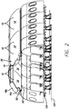
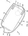
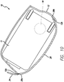
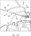
- FIGS. 1-16 show a aircraft storage bin 10.
- the invention can be used on commercial passenger aircraft.
- this is not a limitation on the present invention and the aircraft storage bin can be used elsewhere.
- the present invention aircraft storage bin 10 employs a "clamshell design.”
- the aircraft storage bin 10 allows as much of the entire volume inside the bin as possible to be used, increasing volume and baggage capacity when compared to the prior art.
- the design and structure also provides a way to integrate systems such as environmental control system (“ECS”) ducting and electrical.
- ECS environmental control system
- FIGS. 1-16 show a dual aircraft, storage bin that is essentially two aircraft storage bins 10 that can be installed together in the cabin of an aircraft. However, it will be understood by those of ordinary skill in the art, that a single and separate aircraft storage bin 10 is within the scope of the present invention and is described and claimed herein.
- the figures show aircraft storage bins 10 that are positioned outboard on the aircraft. However, it will be appreciated, that the aircraft storage bin 10 can be used inboard on a wide body aircraft.
- the aircraft storage bin 10 includes a tray or bucket 14 with a first and a second pivot mechanism or pivot axle 16a and 16b on each side, and first and second side panels 18a and 18b.
- the first and second side panels 18a and 18b are referred to herein together as the upper housing 26.
- the aircraft storage bin 10 includes the upper housing 26, which includes the first and second side panels 18a and 18b, and the bucket 14.
- the bucket 14 and upper housing 26 cooperate to define a bin interior 36.
- the bucket 14 defines the lower portion of the bin interior 36 and the upper housing defines the upper portion of the bin interior 36. It will be appreciated that because the aircraft storage bin includes two sides that each have a pivot mechanism and associated components.
- first and second pivot mechanisms/axles are denoted as “16a” and “16b”.
- pivot mechanism/axle may be denoted generally as "16”.
- the first and second side panels 18a and 18b are separate components. However, in another embodiment, the first and second side panels 18a and 18b (the upper housing 26) can be a unitary component.
- the aircraft storage bin 10 includes a single piece bucket 14 that includes a bottom 28 and first and second opposing sides 24a and 24b. In another embodiment, the bucket 14 can include multiple pieces, e.g., a three piece design that includes the bottom 28 and first and second opposing sides 24a and 24b as separate components.
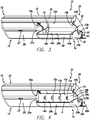
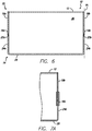
- the bucket 14 and upper housing 26 provide a "clamshell design," where at least a portion of the bottom edge 19a of the first side panel 18a and the bottom edge 19b of the second side panel 18b and the front bottom edge 12a of the strongback 12 meet edge to edge with or abut the top edge 14a of the bucket 14.
- the closed position other than the rear top edge 28b of the bottom 28 of the bucket 14 and the area adjacent thereto and the strongback 12 (see FIG. 8 ), there is little to no overlap between the bucket 14 and the upper housing 26.
- FIG. 8 in the embodiment shown in FIG.
- the bucket 14 does not enter the upper portion of the bin interior 36, which is defined by the upper housing 26, when the bucket 14 is pivoted to the closed position. It will be appreciated by those skilled in the art, that not only does this increase stowage volume and reduce weight by eliminating redundant paneling, but also significantly decreases the number of parts needed for the entire aircraft storage bin 10, compared to the prior art.
- the first and second sides 24a and 24b of the bucket 14 are not received in the upper portion of the bin interior 36.
- the first and second top edges 25a and 25b do not pass or overlap with the first and second bottom edges 19a and 19b when the bucket 14 is pivoted to the closed position.
- the first and second top edges 25a and 25b and first and second bottom edges 19a and 19b abut one another.
- first and second top edges 25a and 25b and first and second bottom edges 19a and 19b are horizontally separated from one another, but, in a vertical direction, the first and second top edges 25a and 25b do not pass or overlap with the first and second bottom edges 19a and 19b when the bucket 14 is pivoted to the closed position.
- first and second side panels 18a and 18b include first and second pivot mechanisms 16a and 16b that are operatively associated with the bucket 14, and allow the bucket 14 to pivot with respect to the upper housing 26 between an open position and a closed position.
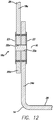
- first and second pivot mechanisms 16a and 16b can be pivot axles, as shown in FIG. 12 .
- first and second pivot mechanisms 16a and 16b or axles pivot or rotate about a pivot axis.
- the first and second pivot mechanisms 16a and 16b are axially aligned such that the pivot axles rotate about the same axis A1, as shown in FIGS. 7C and 8 .
- the aircraft storage bin 10 includes at least one stop member 15 (and preferably a plurality of stop members) positioned within the bin interior 36 and that maintain the bucket 14 in the open position and prevents it from pivoting too far.
- Any type of stop member 15 is within the scope of the present invention.
- the stop member 15 can abut the angled top edge 14b of the back of the bucket 14 and/or the rear top edge 28b of the bottom 28 of the bucket 28.
- the stop member 15 can be a separate component or be built in to the upper housing 26 (e.g., a ledge).
- a pivot axle can extend from the bucket and into an opening in the ear or vice versa. Any pair of pivot mechanisms that are axially aligned and that allow the bucket 14 to pivot with respect to the upper housing 26 is within the scope of the present invention.
- the present invention can utilize a prior art damper, such as a linear damper that includes a cylinder with a piston and damping fluid therein or a spring for assist (as described below).
- a prior art damper such as a linear damper that includes a cylinder with a piston and damping fluid therein or a spring for assist (as described below).
- the aircraft storage bin 10 includes first and second latch assemblies 40a and 40b operatively associated with the first and second side panels 18a and 18b and the first and second sides 24a and 24b of the bucket 14.
- the first latch assembly 40a includes a first hook portion 42a and a first striker portion 44a
- the second latch assembly 40b includes a second hook portion 42b and a second striker portion 44b.
- first hook portion 42a extends downwardly from the bottom edge 19a of the first side panel 18a and the first striker portion 44a is positioned in a first recess 41a defined in the top edge 25 a of the first side 24a of the bucket 14 and the second hook portion 42b extends downwardly from the bottom edge 19b of the second side panel 18b and the second striker portion 44b is positioned in a second recess 41b defined in the top edge 25b of the second side 24b of the bucket 14.
- first hook portion 42a extends upwardly from the top edge 25a of the first side 24a of the bucket 14 and the first striker portion 44a is positioned in a first recess defined in the bottom edge of the first side panel 18a
- second hook portion 42b extends upwardly from the top edge 25b of the second side 24b of the bucket 14 and the second striker portion 44b is positioned in a second recess defined in the bottom edge of the second side panel 18b.
- first striker portion 44a extends downwardly from the bottom edge 19a of the first side panel 18a and the first hook portion 42a is positioned in a first recess 41a defined in the top edge 25 a of the first side 24a of the bucket 14 and the second striker portion 44b extends downwardly from the bottom edge 19b of the second side panel 18b and the second hook portion 42b is positioned in a second recess 41b defined in the top edge 25b of the second side 24b of the bucket 14.
- first hook portion and second hook portion refer to the entire assembly secured to the upper housing in the figures.
- first striker portion and second striker portion refer to the entire assembly secured to the upper housing in the figures.
- the hook portion can be any latching mechanism that includes a hook or latch that mates with or latches to a striker.
- FIGS. 13-15 show an exemplary embodiment of the first latch assembly 40a. It will be understood that the second latch assembly 40b includes essentially the same components.
- FIGS. 13 and 15 show the first latch assembly 40a in the latched position and FIG. 14 shows the first latch assembly 40a in the unlatched position.
- the first hook portion 42a is mounted in a recess 29a in the first side panel 18a and includes a housing 31a, a hook 35a and guide members 37a that help guide the striker 39a (which can be secured in place by a threaded fastener 51a) into the desired position.
- the hook 35a can be mounted on a pivot pin and include a spring 43a for urging it into the desired position.
- the first striker portion 44a includes a housing 45a that defines a guide recess 47a defined therein and that is spanned by the striker 39a.
- the guide members 37a are received in the guide recess 47a, and, as a result of the angle on the bottom edge of the hook 35a and the round shape of the striker 39a, the hook 35a is pivoted out of the way and the striker 39a is received fully between the guide members 37a.
- the spring 43a the hook 35a is urged into the position shown in FIG. 13 , and the first latch assembly 40a is now in the latched position.
- first and second hook portions 42a and 42b extending downwardly from the first and second side panels 18a and 18b and latching to first and second striker portions 44a and 44b, which are essentially embedded in the first and second sides 24a and 24b of the bucket 14 allows the top edge 14a of the bucket 14 (i.e., top edges 25a and 25b and front top edge 28a to abut the bottom edge (bottom edges 19a and 19b and front bottom edge 12a) of the upper housing 26.
- first side panel 18a, the first side 24a of the bucket 14 and the first latch assembly 40a are all lined up generally vertically and the second side panel 18b, the second side 24b of the bucket 14 and the second latch assembly 40b are all lined up generally vertically.
- first and second latch assemblies 40a and 40b shown in the figures are not a limitation on the present invention and any type of latch assembly or mechanism for securing the bucket 14 to the upper housing 26 is within the scope of the present invention.
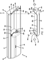
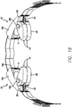
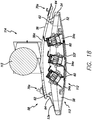
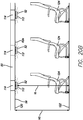
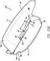
- aircraft storage bin 140 is similar to the aircraft storage bin 10 shown in FIGS. 16 , however, the ears and corresponding indented portions are omitted and are replaced with clevis assemblies 142a and 142b that pivotally connect the upper housing 26 and the bucket 14.
- the clevis assemblies 142a and 142b (together with the pivot mechanisms 16a and 16b) provide the pivotal connection of the bucket to the upper housing.
- FIGS. 22-34 do not include latch assemblies.
- the latch assemblies described above and shown in connection with aircraft storage bin 10 can be used with pivot bin assembly 140. In another embodiment, other latching mechanisms can be used.
- aircraft storage bin 140 generally includes a tray or bucket 14 (or buckets) with a first and a second pivot mechanism or pivot mechanism 16a and 16b on each side, and first and second side panels 18a and 18b and first and second clevis assemblies 142a and 142b.
- the strongback 12 and first and second side panels 18a and 18b are referred to herein together as the upper housing 26.
- the aircraft storage bin 140 includes the upper housing 26, which includes the first and second side panels 18a and 18b, and the bucket 14.
- the bucket 14 and upper housing 26 cooperate to define a bin interior 36.
- the bucket 14 defines the lower portion of the bin interior 36 and the upper housing defines the upper portion of the bin interior 36.
- the aircraft storage 140 includes a plurality of stop members 15 positioned on the bucket 14 that stop the bucket 14 from opening further than the preferred opening position (described below).
- the stop members 15 can be a long strip that spans most or all of the back of the bucket 14 (see FIGS. 33-34 ). In another embodiment, the stop members 15 can be located elsewhere.
- first and second side panels 18a and 18b are separate components.
- the first and second side panels 18a and 18b (the upper housing 26) can be a unitary component.
- first and second side panels 18a and 18b include first and second clevis assemblies 142a and 142b that house first and second pivot mechanisms 16a and 16b together with other components as described below.
- first and second pivot mechanisms 16a and 16b are operatively associated with the bucket 14, and allow the bucket 14 to pivot with respect to the upper housing 26 between an open position and a closed position.
- first and second pivot mechanisms 16a and 16b or axles define a pivot axis.
- the first and second pivot mechanisms 16a and 16b are axially aligned.
- aircraft storage bin 140 includes a connecting unit 150 (described more fully below) on each side thereof, that, together with first and second pivot bin mechanisms 16a and 16b are housed within clevis assemblies 142a and 142b.
- First and second clevis assemblies 142a and 142b are connected to the first and second side panels 18a and 18b and extend downwardly to surround a portion of the sides first and second sides 24a and 24b of bucket 14.
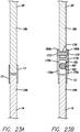
- the pivot mechanisms 16a and 16b are essentially the clevis pins and the clevis is comprised of an inner plate 175 and an outer plate 177 that each include an opening 179 therein, through which the pivot mechanism/pin 16 extends.
- pivot axle 16b extends through lower arms 176b of the clevis assembly 142b, which, together with the clevis assembly and pivot axle on the other side of the bucket 14 provide a pivotal connection between the upper housing 26 and the bucket 14.
- the first and second clevis assemblies 142a and 142b can be connected to the upper housing 26 and bucket 14 by fasteners, threaded fasteners, bonding or the like.
- the clevis assemblies 142a and 142b are integral with the upper housing 26.
- the clevis assemblies can be integral with the bucket 14 or can be attached/secured to the bucket and the pivot axles can extend through the upper housing. As shown in FIG.
- second clevis assembly 142b includes threaded fasteners 173 that extend into a bushing 178 positioned in an opening in the side 18b.
- Pivot axle 16b can also extend through a bushing 178 positioned in openings 179 in the inner and outer plates 175 and 177 and an opening 182 in the side of the bucket 14.
- bushing 178 can be omitted.
- the clevis assemblies 142a and 142b (and the inner and outer plates 175 and 177 thereof) can each be a unitary structure or they can be a plurality of plates that together form the clevis assembly. As shown in FIG.
- the clevis assembly can include a horizontal plate 181 that connects the inner and outer plates 175 and 177.
- the pivot axle can be unitary with or secured to the inside surfaces of the inner and outer plates/lower arms or at least one of the inner or outer plates/lower arms.
- the clevis assemblies can include a single inner or outer plate that extends between and is secured to the upper housing and the bucket.
- FIG. 23D in an embodiment that includes the rotary damper 17 and/or an assist spring 172 (described below), these components are also housed within the clevis assembly 142b.
- FIG. 23D also shows clevis assembly 142b including connectors that are unitary with the inside surface of upper arms 180b of the clevis.
- the aircraft storage bin 140 includes a system that provides a user with assistance in closing an open bucket 14 with a predetermined minimal amount of force, and may also provide the means for a fully loaded closed bucket 14 to open in a controlled manner (damped). This can be accomplished in several ways.
- FIGS. 24-30 show a preferred embodiment for providing these features.
- certain dimensions, weights, forces and other measurements, etc. are required or desired for opening and closing overhead bins and for the forces necessary for particular sized men and women to close the bins. Such considerations are taken into account in the description herein.
- the particular numbers, measurements, dimensions, etc. set forth herein are only exemplary and not limiting on the present invention.
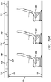
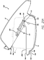
- FIG. 24 shows a side view of aircraft storage bin 140 in the open position.
- Two different open positions for the bucket 14 are shown. This is referred to herein as a two stage opening bucket or bin.
- the position shown in the solid lines is the bucket 14 in the open position when the pivot bin is empty (referred to herein as the "intermediate open position”).
- the position shown in dotted lines is the bucket 14 in the open position when the aircraft storage bin is loaded beyond a predetermined weight (referred to herein as the "open position").
- the bucket 14 can open fully to a certain angle or arc, which is shown in FIG. 24 as A1. When the bucket 14 is open to A1, it is in the open position (stop members 15 maintain the bucket 14 in the open position).
- A1 is 42°
- A2 is 31°
- A3 is 11°.
- A1 can be between 30° and 60°
- A2 can be between 20° and 40°
- A3 can be between 5° and 20°.
- An assist spring or springs can be used to hold the bucket 14 in the intermediate open position, as will be described further below.
- the two stage opening can be omitted and the bucket 14 can open all the way through arc A1 when opened.
- the bin is damped when opened. This prevents the bucket 14 from slamming open as a result of gravity. Damping can be provided in several ways, as described below.
- a closing assist force is provided along at least a portion of the closing arc of the bucket 14 (shown as an exemplary A3 in FIG. 24 ).
- the closing assist force created by the preloaded spring will help along arc A3, which is the portion of the closing arc that requires the most force by a user.
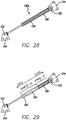
- FIGS. 28-29 show schematic views of connector units 150a and 150b.
- Both connector units 150a and 150b include pivotal connections 152 (e.g. ball joints) at the opposite ends thereof that connect the unit to brackets 154 or the like that is located on the bucket 14 and the side wall 18 respectively.
- the connecting units 150 pivot about pivotal connections 152 as necessary and lengthen or contract as necessary during opening or closing of the bucket 14.
- Connecting unit 150a includes two different springs 156 and 158 that are used to provide closing assist over two different portions of the closing arc A1.
- a variable or two stage spring can be used to provide the same result. These two different portions may coincide with arcs A2 and A3 or they may not.
- connecting unit 150a can also include damping capability.
- Connecting unit 150b includes closing assist over at least a portion of closing arc A1 and also provides damping during opening of the bucket 14.
- spring assist is provided over closing during bucket travel along A3 and damping while opening over at least A2 (and preferably all of A1).
- Damping can be provided in any known way.
- damping is provided by fluid 160 disposed within a cylinder 162, as shown in FIG. 29 . Pneumatic or gas cylinders can also be used.
- the connecting units 150 preferably provide a spring lift assist during at least this portion of the closing process.
- connecting units 150 are provided on both sides of the bucket 14 and can be connected to the bucket 14 and upper housing 26 by any connection method or interface and preferably using brackets 154 with an opening therethrough or a stud extending therefrom.
- the aircraft storage bin 140 can include a powered lift assist connecting unit 150c, which provides powered lift assist over at least a portion of or the entire closing arc A1.
- Powered opening/damping can also be provided.
- a powered lift assist connecting unit 150c is used on one side of the bucket 14 and a connecting unit 150 with only damping capability is used on the other side of the bucket 14.
- powered lift assist connecting units 150c can be used on both sides of the bucket 14. It will be appreciated that all of the connecting units 150a, 150b and 150c (and any connecting units 150 with only damping capability) are all interchangeable and use the same interface (e.g., brackets 154) to connect to the bucket 14 and upper housing 26.
- brackets 154 may have to be moved to accommodate the powered lift assist connecting unit 150c as opposed to the other connecting units 150. It will be appreciated that the powered lift assist connecting unit 150c is in electrical communication with the release button 27 of the associated bucket 14. In another embodiment, a separate button for closing can be provided.
- FIG. 23D shows another embodiment that provides damping of the opening bucket and/or mechanical/spring assistance in closing the bucket 14.
- FIG. 23D is a cross-section that is taken at the same cut line as FIG. 23C in a pivot bin assembly with the embodiment now being described.
- the clevis assembly 142b includes at least one assist spring 172.
- the assist spring 172 is a coil spring that is co-axial with pivot mechanism 16. In use, at least one end of the spring abuts a stop such that when the bucket 14 is opened passed a predetermined point (e.g., after A2), the spring 172 is preloaded. In the example shown in FIG. 24 , spring 172 holds the empty bucket in the intermediate open position.
- the bucket opens further and spring 172 is preloaded. This provides a user closing the bin with assistance. It will be appreciated that once the bucket 14 is loaded, the bucket 14 only moves between the open and closed positions. In this configuration it bypasses the intermediate open position as the weight of the luggage overcomes the spring force.
- the assist spring 172 can be a spiral spring or other type of spring.
- This embodiment can include the same benefits as those discussed above with respect to the various connecting units 150.
- coil spring 172 can provide closing assist over a portion of the closing arc or over the entire closing arc or a variable/two stage spring or multiple springs can be used to provide differing amounts of closing force assistance over the closing arc.
- closing assist can be provided during one portion of the closing arc by coil springs 172 and during another portion of the closing arc by spring 156 in connecting unit 150.
- the aircraft storage bin 140 can include a) damping capability, b) damping capability and closing assist, c) damping capability and two or more stage closing assist, or d) damping capability and powered lift assist.
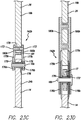
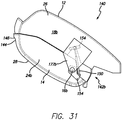
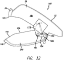
- FIGS. 31-34 show another arrangement of the clevis assemblies 142a and 142b together with the cut out 151 in the side 18b of the upper housing 26 and the connecting unit 150.
- inner plates 175a and 175b and outer plates 177a and 177b and cut outs 151 are shaped differently and connecting units 150 are oriented differently.
- the pivot mechanisms 16a and 16b extend through the lower brackets 154.
- this embodiment operates the same as that described above.
- the damping capability of the aircraft storage bin 10 or 140 allows damped opening of the bucket 14 to an angle (the intermediate open position) that provides easy access for most luggage, even when empty.
- the aircraft storage bins 10 or 140 increase the headroom in the cabin when the buckets 14 are open and empty (in the intermediate open position).
- the bucket 14 will drop to the open position in a controlled/damped manner. This allows for placement of all luggage sizes.
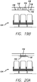
- FIGS. 24-27 an example of an operation cycle of loading and unloading a two stage opening bucket or bin with luggage before and after a flight will now be described.
- the release button 27 of an empty bucket 14 is pressed by a user.
- the bucket 14 opens 31° (A2) at a damped rate to the intermediate open position (see the bucket in dashed lines in FIG. 26 ).
- the springs (springs 156 in the connector assemblies and/or coil springs 172) are now ready to be engaged.
- the user places luggage 11 on the lip of the bucket 14 (or pulls down with their hand).
- the potential energy from the luggage 11 lowers the bucket 14 through an additional 11° (A3) to the open position, which displaces the springs 156, 158 and/or 172 on both sides of the bucket 14 and loads them with enough energy to create 1.80 m-Kg (13 ft-lbs) of torque (for example).
- the user then slides their luggage fully into the bucket 14 (see FIG. 27 ).
- the users bag is preferably turned so that it rests on a side.
- the bucket 14 is damped while it is lowered.
- F1 is approximately vertical.
- the closing surface 146 is configured such that it is parallel or close to parallel with the ground. This prompts a user to press up in the direction of F1, which makes closing the bucket easier than pushing elsewhere on the bucket or pushing on a surface that is at a steep angle compared to horizontal.
- the user presses the release button 27 and the fully loaded bucket 14 opens the full 42° (A1) to the open position at a damped rate. The user can then pull their luggage 11 from the fully opened bucket 14.
- the bucket 14 free falls from the closed to open position in 2.5 ⁇ 1 seconds while loaded with luggage anywhere between 0 - 36.3 kg (0-80 lbs) in weight.
- the bucket 14 itself weighs approximately 4.53 Kg (10 lbs) This results in a combined weight range of 4.53 - 40.82 Kg (10 - 90 lbs) (but could be higher).
- the closing force it is desired for the closing force (provided by the user) not to exceed 12.25 Kg (27 lbs).
- a closing assist force of approximately 3.18 Kg (7 lbs) is provided over the first 11° (A3) of the bucket 14 closing motion. This equates to approximately 1.80 m-Kg (13 ft-lbs) of torque at the pivot point.
- the two stage opening bucket also provides for two different orientations for placing standard luggage in the bin interior 36.
- A2 is dimensioned such that when the bucket 14 is in the intermediate open position, a bag can be placed in the bucket 14 on its top or bottom, as shown in dashed lines in FIG. 26 and A1 is dimensioned such that when the bucket 14 is in the open position, a bag can be placed in the bucket 14 on its side, as shown in solid lines in FIG. 26 .
- the bucket 14 when the bucket 14 is in the intermediate open position, a user can place their bag on the lip of the bucket 14 on its top or bottom, allow the weight of the bag to open the bin to the open position and then turn the bag on its side and slide it all the way into the bin interior 36.
- the two stage opening capability can be applied to other overhead bins, e.g., bins that open by translating or moving downwardly as opposed to pivoting open.
Claims (11)
- Flugzeugablagebehälter (140), Folgendes beinhaltend:ein oberes Gehäuse (26), welches erste und zweite Seitenpaneele (18a, 18b) beinhaltet, an welchen folgende Elemente angeordnet sind:eine erste Bügelanordnung (142a), beinhaltend mindestens eine von einer ersten inneren Platte (175a) und einer ersten äußeren Platte (177a), undeine zweite Bügelanordnung (142b), beinhaltend mindestens eine von einer zweiten inneren Platte (175b) und einer zweiten äußeren Platte (177b),einen Eimer (14), beinhaltend einen Boden (28) und erste und zweite Seiten (24a, 24b), wobei der Eimer mit dem oberen Gehäuse zusammenarbeitet, um ein Behälterinneres zu bilden,einen ersten Schwenkmechanismus (16a), funktionsfähig verbunden mit dem Eimer und der ersten Bügelanordnung, undeinen zweiten Schwenkmechanismus (16b), funktionsfähig verbunden mit dem Eimer und der zweiten Bügelanordnung, wobei die ersten und zweiten Schwenkmechanismen eine Schwenkachse (A1) definieren, und wobei der Eimer um die Schwenkachse in Bezug auf das obere Gehäuse zwischen einer geöffneten Position und einer geschlossenen Position schwenkt.
- Flugzeugablagebehälter (140) nach Anspruch 1, bei welchem
die erste Seite (24a) des Eimers (14) eine erste Seitenwand ist;
die zweite Seite (24b) des Eimers (14) eine zweite Seitenwand ist;
die erste Bügelanordnung (142a) sich zwischen dem ersten Seitenpaneel (18a) des oberen Gehäuses (26) und der ersten Seitenwand des Eimers erstreckt;
die zweite Bügelanordnung (142b) sich zwischen dem zweiten Seitenpaneel (18b) des oberen Gehäuses und der zweiten Seitenwand des Eimers erstreckt. - Flugzeugablagebehälter (140) nach Anspruch 1, bei welchem
der Flugzeugablagebehälter eine Schwenkbehälteranordnung ist, die konfiguriert ist, um Gepäck aufzunehmen und im Innern eines Flugzeugs positioniert zu werden;
das obere Gehäuse (26) eine Verstärkung (12) beinhaltet;
die erste Bügelanordnung (142a) am ersten Seitenpaneel (18a) gesichert ist und sich von diesem nach unten erstreckt;
die zweite Bügelanordnung (142b) am zweiten Seitenpaneel (18b) gesichert ist und sich von diesem nach unten erstreckt;
der erste Schwenkmechanismus (16a) eine erste Schwenkachse ist;
der zweite Schwenkmechanismus (16b) eine zweite Schwenkachse ist; und
die ersten und zweiten Schwenkmechanismen (16a, 16b) axial entlang der Schwenkachse (A1) ausgerichtet sind. - Flugzeugablagebehälter (140) nach einem der vorhergehenden Ansprüche, zudem beinhaltend eine erste Verbindungseinheit (150a, 150c) mit einem ersten Ende, das schwenkbar mit der ersten Seite (24a) des Eimers (14) verbunden ist und einem zweiten Ende, das schwenkbar mit dem ersten Seitenpaneel (18a) verbunden ist, und eine zweite Verbindungseinheit (150b, 150c) mit einem ersten Ende, das schwenkbar mit der zweiten Seite (24b) des Eimers (14) verbunden ist und einem zweiten Ende, das schwenkbar mit dem zweiten Seitenpaneel (18b) verbunden ist, wobei die ersten und zweiten Verbindungseinheiten eine oder beide der Funktionen bieten, bestehend aus Dämpfung, wenn der Eimer in die geöffnete Position schwenkt und, und aus Unterstützung, wenn der Eimer in die geschlossene Position schwenkt.
- Flugzeugablagebehälter (140) nach Anspruch 4, bei welchem die erste Bügelanordnung (142a) sowohl die erste innere Platte (175a) als auch die erste äußere Platte (177a) beinhaltet, wobei der erste Schwenkmechanismus (16a) sich zwischen der ersten inneren Platte und der ersten äußeren Platte erstreckt, wobei die zweite Bügelanordnung (142b) sowohl die zweite innere Platte (175b) als auch die zweite äußere Platte (177b) beinhaltet, wobei der zweite Schwenkmechanismus (16b) sich zwischen der zweiten inneren Platte und der zweiten äußeren Platte erstreckt, und wobei die erste Verbindungseinheit (150a, 150c) zwischen der ersten inneren Platte und der ersten äußeren Platte positioniert ist und die zweite Verbindungseinheit (150b, 150c) zwischen der zweiten inneren Platte und der zweiten äußeren Platte positioniert ist.
- Flugzeugablagebehälter (140) nach einem der vorhergehenden Ansprüche, bei welchem mindestens einer des ersten und des zweiten Schwenkmechanismus (16a, 16b) eine Unterstützungsfeder (172) beinhaltet, die hiermit verbunden ist, und wobei die Unterstützungsfeder (172) vorgespannt wird, wenn der Eimer (14) in die geöffnete Position geschwenkt wird; und, optionsweise, wobei die Unterstützungsfeder (172) eine Wendelfeder ist, die koaxial mit dem ersten oder zweiten Schwenkmechanismus ausgerichtet ist.
- Flugzeugablagebehälter (140) nach Anspruch 5, bei welchem mindestens eine der ersten und der zweiten Verbindungseinheit (150a, 150b, 150c) eine hiermit verbundene Unterstützungsfeder beinhaltet, und wobei die Unterstützungsfeder vorgespannt wird, wenn der Eimer in die geöffnete Position geschwenkt wird.
- Flugzeugablagebehälter (140) nach einem der vorhergehenden Ansprüche, bei welchem das obere Gehäuse (26) ein Stoppglied (15) beinhaltet, und bei welchem der Boden (28) des Eimers (14) eine hintere Oberkante (14b) beinhaltet, die am Stoppglied anschlägt, wenn der Eimer in der geöffneten Position steht.
- Flugzeugablagebehälter (140) nach Anspruch 3 oder 1, bei welchem der erste Schwenkmechanismus (16a) sich durch die erste Seite (24a) des Eimers (14) und zwischen den ersten inneren und äußeren Platten (175a, 177a) erstreckt und der zweite Schwenkmechanismus (16b) sich durch die zweite Seite (24b) des Eimers und zwischen den zweiten inneren und äußeren Platten (175b, 177b) erstreckt.
- Schwenkbehälteranordnung (140) nach Anspruch 9, weiterhin beinhaltend erste und zweite Schnappanordnungen (40a, 40b), bei welcher die erste Schnappanordnung (40a) mit dem ersten Seitenpaneel (18a) und der ersten Seite (24a) des Eimers (14) verbunden ist, und bei welchem die zweite Schnappanordnung (40b) mit dem zweiten Seitenpaneel (18b) und der zweiten Seite (24b) des Eimers verbunden ist.
- Schwenkbehälteranordnung (140) nach Anspruch 10, bei welcher die erste Schnappanordnung (40a) einen ersten Hakenabschnitt und einen ersten Schließerabschnitt beinhaltet, wobei einer des ersten Hakenabschnitts (42a) und des ersten Schließerabschnitts (44a) mit dem ersten Seitenpaneel (18a) verbunden ist, und der andere des ersten Hakenabschnitts (42a) und des ersten Schließerabschnitts (44a) mit der ersten Seite (24a) des Eimers verbunden ist, wobei die zweite Schnappanordnung (40b) einen zweiten Hakenabschnitt (42b) und einen zweiten Schließerabschnitt (44b) beinhaltet, wobei einer des zweiten Hakenabschnitts und des zweiten Schließerabschnitts mit dem zweiten Seitenpaneel (18b) verbunden ist, und der andere des zweiten Hakenabschnitts und des zweiten Schließerabschnitts mit der zweiten Seite (24b) des Eimers verbunden ist.
Priority Applications (1)
| Application Number | Priority Date | Filing Date | Title |
|---|---|---|---|
| EP17184027.5A EP3275785B1 (de) | 2013-02-12 | 2014-02-13 | Schwenkbehälteranordnung |
Applications Claiming Priority (6)
| Application Number | Priority Date | Filing Date | Title |
|---|---|---|---|
| US13/765,652 US9162617B2 (en) | 2012-02-14 | 2013-02-12 | Pivot bin assembly |
| US201361764503P | 2013-02-13 | 2013-02-13 | |
| US201361809281P | 2013-04-05 | 2013-04-05 | |
| US201361835896P | 2013-06-17 | 2013-06-17 | |
| US14/179,494 US8955805B2 (en) | 2012-02-14 | 2014-02-12 | Pivot bin assembly |
| PCT/US2014/016313 WO2014127161A1 (en) | 2013-02-12 | 2014-02-13 | Pivot bin assembly |
Related Child Applications (1)
| Application Number | Title | Priority Date | Filing Date |
|---|---|---|---|
| EP17184027.5A Division EP3275785B1 (de) | 2013-02-12 | 2014-02-13 | Schwenkbehälteranordnung |
Publications (3)
| Publication Number | Publication Date |
|---|---|
| EP2956360A1 EP2956360A1 (de) | 2015-12-23 |
| EP2956360A4 EP2956360A4 (de) | 2016-12-14 |
| EP2956360B1 true EP2956360B1 (de) | 2017-08-16 |
Family
ID=51354553
Family Applications (2)
| Application Number | Title | Priority Date | Filing Date |
|---|---|---|---|
| EP17184027.5A Active EP3275785B1 (de) | 2013-02-12 | 2014-02-13 | Schwenkbehälteranordnung |
| EP14751181.0A Active EP2956360B1 (de) | 2013-02-12 | 2014-02-13 | Schwenkbehälteranordnung |
Family Applications Before (1)
| Application Number | Title | Priority Date | Filing Date |
|---|---|---|---|
| EP17184027.5A Active EP3275785B1 (de) | 2013-02-12 | 2014-02-13 | Schwenkbehälteranordnung |
Country Status (7)
| Country | Link |
|---|---|
| EP (2) | EP3275785B1 (de) |
| JP (5) | JP6110513B2 (de) |
| CN (3) | CN105189289B (de) |
| BR (1) | BR112015019319A2 (de) |
| CA (4) | CA3013823C (de) |
| RU (1) | RU2615898C2 (de) |
| WO (1) | WO2014127161A1 (de) |
Families Citing this family (19)
| Publication number | Priority date | Publication date | Assignee | Title |
|---|---|---|---|---|
| AT513939A1 (de) * | 2013-02-01 | 2014-08-15 | Facc Ag | Überkopf-Gepäckfach für Flugzeuge und Flugzeug mit solchen Überkopf-Gepäckfächern |
| CN105189289B (zh) * | 2013-02-13 | 2016-09-14 | C&D佐迪阿克公司 | 枢转仓组件 |
| EP3212501B1 (de) * | 2014-10-27 | 2020-09-09 | C&D Zodiac, Inc. | Überkopfgepäckablageverriegelungssystem |
| US9630718B2 (en) * | 2015-02-06 | 2017-04-25 | The Boeing Company | Variable opening overhead stowage bins and related methods |
| US10315768B2 (en) | 2015-11-03 | 2019-06-11 | Facc Ag | Overhead luggage compartment for an aircraft |
| EP3339172B1 (de) * | 2016-12-21 | 2022-12-07 | Airbus Defence and Space GmbH | Gepäckablagesystem, luftfahrzeug und verfahren zu dessen betrieb |
| US10907392B2 (en) * | 2017-01-23 | 2021-02-02 | Safran Cabin Inc. | Pivot bin with lift assist assembly and method of use thereof |
| EP3655321A1 (de) | 2017-07-17 | 2020-05-27 | Harper Engineering Company | Integrierte staubehälteranordnung |
| US10889376B2 (en) * | 2018-02-28 | 2021-01-12 | The Boeing Company | Powered stowage bin assemblies |
| CN108482679B (zh) * | 2018-03-19 | 2023-09-29 | 成都飞机工业(集团)有限责任公司 | 一种同时吊装两架无人机的吊舱系统 |
| US10850845B2 (en) * | 2018-09-18 | 2020-12-01 | The Boeing Company | Overhead payload module with integrated stowbins |
| WO2020097219A1 (en) | 2018-11-06 | 2020-05-14 | Safran Cabin Inc. | Reconfigurable aircraft galley monument |
| CN114269647A (zh) * | 2019-10-03 | 2022-04-01 | 三菱重工Rj航空公司 | 飞机的头顶行李舱及其改进方法 |
| DE102020000835A1 (de) | 2020-02-08 | 2021-08-12 | Diehl Aviation Laupheim Gmbh | Staufach für ein Flugzeug sowie Flugzeug mit dem Staufach |
| DE102020000834B4 (de) | 2020-02-08 | 2022-11-24 | Diehl Aviation Laupheim Gmbh | Staufach für ein Flugzeug sowie Flugzeug mit dem Staufach |
| DE102020104988A1 (de) | 2020-02-26 | 2021-08-26 | Airbus Operations Gmbh | Staufach für eine Kabine eines Fahrzeugs |
| US20230026534A1 (en) * | 2021-07-21 | 2023-01-26 | Safran Cabin Inc. | Overhead storage bin pivot latch mechanism |
| CN113771772B (zh) * | 2021-11-10 | 2022-01-04 | 宁波华众塑料制品有限公司 | 一种汽车后备箱储物盒 |
| AT526479A1 (de) * | 2022-09-06 | 2024-03-15 | Facc Ag | Gepäckfach für ein Flugzeug |
Family Cites Families (40)
| Publication number | Priority date | Publication date | Assignee | Title |
|---|---|---|---|---|
| US4637642A (en) | 1983-12-16 | 1987-01-20 | The Boeing Company | Stowage bin latch assembly |
| US5096271A (en) * | 1991-03-29 | 1992-03-17 | Sony Trans Com, Inc. | Drive assembly, power off retract |
| JP3304188B2 (ja) * | 1994-02-23 | 2002-07-22 | 株式会社ニフコ | 一方向回転ダンパー |
| US5549258A (en) * | 1994-12-23 | 1996-08-27 | Heath Tecna Aerospace Company | Retrofit luggage bin assembly compatible with existing aircraft bin supports |
| US5567028A (en) | 1995-02-27 | 1996-10-22 | The Boeing Company | Mechanism for translating storage bin |
| US5842668A (en) * | 1997-02-27 | 1998-12-01 | Hexcel Corporation | Quick fit overhead stowage compartment |
| US5934615A (en) * | 1997-08-25 | 1999-08-10 | Hexcel Corporation | Luggage bins with articulating mechanism |
| US6357842B1 (en) * | 1999-01-25 | 2002-03-19 | Bruce E. Nott | Overhead storage device |
| DE19902666C1 (de) * | 1999-01-26 | 2000-06-15 | Daimler Chrysler Ag | Ablagekasten für Fahrzeuge |
| US6398163B1 (en) * | 1999-06-10 | 2002-06-04 | Jerry Welch | Enhanced luggage bin system |
| DE10063932C2 (de) * | 2000-12-20 | 2002-11-28 | Airbus Gmbh | Gepäckablage mit einem absenkbaren Gepäckfach, insbesondere für eine Flugzeugpassagierkabine |
| AT410657B (de) * | 2001-10-09 | 2003-06-25 | Fischer Adv Components Gmbh | Überkopf-gepäckablagebehälter, insbesondere für flugzeuge |
| AT413812B (de) * | 2001-10-17 | 2006-06-15 | Fischer Adv Components Gmbh | Aufhängevorrichtung für absenkbare gebäckablagebehälter |
| JP4046554B2 (ja) * | 2002-06-12 | 2008-02-13 | 嘉信 香取 | 飛行機の手荷物収納庫 |
| US20060175368A1 (en) * | 2005-02-04 | 2006-08-10 | Cts Fahrzeug Dachysteme Gmbh | Modular roof cargo container movable to a rear loading position |
| JP5020831B2 (ja) * | 2005-02-15 | 2012-09-05 | エアバス・ソシエテ・パル・アクションス・シンプリフィ | 航空機の荷物室 |
| US7234666B2 (en) * | 2005-03-02 | 2007-06-26 | The Boeing Company | Pivoting storage bin and method of making |
| FR2892702B1 (fr) * | 2005-10-28 | 2008-01-11 | Airbus Sas | Rangement pour bagages destine notamment a une cabine d'aeronef |
| US7302150B2 (en) * | 2006-04-27 | 2007-11-27 | The Boeing Company | Illuminated latch indicator assembly |
| US20080078871A1 (en) * | 2006-08-25 | 2008-04-03 | The Boeing Company | System and method for electronically latching compartments |
| US7887008B2 (en) * | 2006-08-25 | 2011-02-15 | The Boeing Company | System and method for a power-assisted compartment |
| DE102006045189B4 (de) * | 2006-09-25 | 2008-11-27 | Airbus Deutschland Gmbh | Kraftunterstützungssystem |
| KR100832230B1 (ko) * | 2006-10-12 | 2008-05-23 | 가부시키가이샤 니프코 | 가동체의 동작장치 및 리드장치 |
| US7762737B2 (en) * | 2006-11-09 | 2010-07-27 | The Boeing Company | System and method for stowage compartment pivot assembly |
| DE102007030331A1 (de) * | 2007-06-29 | 2009-01-02 | Airbus Deutschland Gmbh | Staufachmodul für einen Innenraum eines Flugzeugs |
| DE102007030330B4 (de) * | 2007-06-29 | 2010-07-22 | Airbus Deutschland Gmbh | Schwenkbarer Geräteträger in Kombination mit modifizierter Gepäckablage |
| JP2009166582A (ja) * | 2008-01-15 | 2009-07-30 | Panasonic Corp | 開閉式表示装置 |
| AT506980B1 (de) * | 2008-07-11 | 2010-07-15 | Gottfried Steiner Ingenieurbue | Gepäckablage für ein passagierflugzeug |
| DE102008058271A1 (de) * | 2008-11-20 | 2010-05-27 | Airbus Deutschland Gmbh | Versorgungseinheit für flexible Versorgungskanäle |
| JP5193115B2 (ja) * | 2009-04-01 | 2013-05-08 | 株式会社ニフコ | 可動体の動作機構 |
| DE102009051363A1 (de) * | 2009-10-30 | 2011-05-05 | Airbus Operations Gmbh | Staufachmodul mit beweglichem Staufach |
| US8262022B2 (en) * | 2009-12-15 | 2012-09-11 | The Boeing Company | Overhead stowage bin load transfer and balance system |
| WO2011133702A1 (en) * | 2010-04-20 | 2011-10-27 | C&D Zodiac, Inc. | Pivot bin assembly |
| US8943751B2 (en) * | 2010-04-20 | 2015-02-03 | Be Intellectual Property, Inc. | Lift assist mechanism |
| US20120074258A1 (en) * | 2010-09-23 | 2012-03-29 | Be Intellectual Property, Inc. | Integrated aircraft interior |
| DE102011110750B4 (de) * | 2011-08-16 | 2021-08-05 | Diehl Aviation Laupheim Gmbh | Gepäckablagefach für ein Flugzeug |
| US8899390B2 (en) | 2012-02-14 | 2014-12-02 | C&D Zodiac, Inc. | Freewheeling rotary damping mechanism |
| US20130209221A1 (en) | 2012-02-14 | 2013-08-15 | C&D Zodiac, Inc. | Rotary damping mechanism with pivotal vanes |
| US9162617B2 (en) * | 2012-02-14 | 2015-10-20 | C&D Zodiac, Inc. | Pivot bin assembly |
| CN105189289B (zh) * | 2013-02-13 | 2016-09-14 | C&D佐迪阿克公司 | 枢转仓组件 |
-
2014
- 2014-02-13 CN CN201480008389.2A patent/CN105189289B/zh active Active
- 2014-02-13 EP EP17184027.5A patent/EP3275785B1/de active Active
- 2014-02-13 WO PCT/US2014/016313 patent/WO2014127161A1/en active Application Filing
- 2014-02-13 CA CA3013823A patent/CA3013823C/en not_active Expired - Fee Related
- 2014-02-13 EP EP14751181.0A patent/EP2956360B1/de active Active
- 2014-02-13 BR BR112015019319A patent/BR112015019319A2/pt active Search and Examination
- 2014-02-13 CA CA2898647A patent/CA2898647C/en not_active Expired - Fee Related
- 2014-02-13 CA CA2931576A patent/CA2931576C/en not_active Expired - Fee Related
- 2014-02-13 CN CN201610557338.6A patent/CN106114868B/zh active Active
- 2014-02-13 RU RU2015138913A patent/RU2615898C2/ru active
- 2014-02-13 CN CN201610139931.9A patent/CN105775138B/zh active Active
- 2014-02-13 CA CA2938085A patent/CA2938085C/en not_active Expired - Fee Related
- 2014-02-13 JP JP2015558136A patent/JP6110513B2/ja active Active
-
2016
- 2016-09-26 JP JP2016186799A patent/JP6321746B2/ja active Active
-
2018
- 2018-03-28 JP JP2018061674A patent/JP6592131B2/ja active Active
-
2019
- 2019-06-13 JP JP2019110183A patent/JP6864038B2/ja active Active
-
2021
- 2021-02-04 JP JP2021016626A patent/JP7114761B2/ja active Active
Non-Patent Citations (1)
| Title |
|---|
| None * |
Also Published As
| Publication number | Publication date |
|---|---|
| CA2931576C (en) | 2018-05-29 |
| JP2021079944A (ja) | 2021-05-27 |
| RU2015138913A (ru) | 2017-03-20 |
| JP6110513B2 (ja) | 2017-04-05 |
| CA2898647C (en) | 2016-11-08 |
| CN106114868A (zh) | 2016-11-16 |
| JP2019196170A (ja) | 2019-11-14 |
| JP2017001672A (ja) | 2017-01-05 |
| EP3275785A1 (de) | 2018-01-31 |
| JP6592131B2 (ja) | 2019-10-16 |
| CA2898647A1 (en) | 2014-08-21 |
| CN105189289B (zh) | 2016-09-14 |
| CN105189289A (zh) | 2015-12-23 |
| WO2014127161A1 (en) | 2014-08-21 |
| CA3013823A1 (en) | 2014-08-21 |
| JP6864038B2 (ja) | 2021-04-21 |
| CA2938085C (en) | 2018-12-04 |
| EP2956360A4 (de) | 2016-12-14 |
| BR112015019319A2 (pt) | 2020-01-28 |
| CN105775138A (zh) | 2016-07-20 |
| JP2016513037A (ja) | 2016-05-12 |
| CN106114868B (zh) | 2017-11-21 |
| CA2931576A1 (en) | 2014-08-21 |
| CA2938085A1 (en) | 2014-08-21 |
| EP3275785B1 (de) | 2018-09-12 |
| JP7114761B2 (ja) | 2022-08-08 |
| RU2615898C2 (ru) | 2017-04-11 |
| JP2018108822A (ja) | 2018-07-12 |
| EP2956360A1 (de) | 2015-12-23 |
| JP6321746B2 (ja) | 2018-05-09 |
| CN105775138B (zh) | 2017-11-21 |
| CA3013823C (en) | 2020-07-07 |
Similar Documents
| Publication | Publication Date | Title |
|---|---|---|
| EP2956360B1 (de) | Schwenkbehälteranordnung | |
| US10000286B2 (en) | Pivot bin assembly with lift assist | |
| US10336454B2 (en) | Pivot bin bucket with slot for receiving pivot axle | |
| US10112717B2 (en) | Pivot bin assembly with two part pivot axle | |
| EP3166847B1 (de) | Schwenkbehälteranordnung | |
| EP3250082B1 (de) | Gelenkbehälteranordnung mit minimaler erforderlicher kraft zum verschliessen |
Legal Events
| Date | Code | Title | Description |
|---|---|---|---|
| PUAI | Public reference made under article 153(3) epc to a published international application that has entered the european phase |
Free format text: ORIGINAL CODE: 0009012 |
|
| 17P | Request for examination filed |
Effective date: 20150730 |
|
| AK | Designated contracting states |
Kind code of ref document: A1 Designated state(s): AL AT BE BG CH CY CZ DE DK EE ES FI FR GB GR HR HU IE IS IT LI LT LU LV MC MK MT NL NO PL PT RO RS SE SI SK SM TR |
|
| AX | Request for extension of the european patent |
Extension state: BA ME |
|
| DAX | Request for extension of the european patent (deleted) | ||
| A4 | Supplementary search report drawn up and despatched |
Effective date: 20161115 |
|
| RIC1 | Information provided on ipc code assigned before grant |
Ipc: B64D 11/00 20060101AFI20161109BHEP |
|
| GRAP | Despatch of communication of intention to grant a patent |
Free format text: ORIGINAL CODE: EPIDOSNIGR1 |
|
| INTG | Intention to grant announced |
Effective date: 20170309 |
|
| RIN1 | Information on inventor provided before grant (corrected) |
Inventor name: WILLIAMS, COREY Inventor name: KEARSEY, STEPHEN Inventor name: SAVIAN, SCOTT |
|
| GRAS | Grant fee paid |
Free format text: ORIGINAL CODE: EPIDOSNIGR3 |
|
| GRAA | (expected) grant |
Free format text: ORIGINAL CODE: 0009210 |
|
| AK | Designated contracting states |
Kind code of ref document: B1 Designated state(s): AL AT BE BG CH CY CZ DE DK EE ES FI FR GB GR HR HU IE IS IT LI LT LU LV MC MK MT NL NO PL PT RO RS SE SI SK SM TR |
|
| REG | Reference to a national code |
Ref country code: GB Ref legal event code: FG4D |
|
| REG | Reference to a national code |
Ref country code: CH Ref legal event code: EP |
|
| REG | Reference to a national code |
Ref country code: IE Ref legal event code: FG4D |
|
| REG | Reference to a national code |
Ref country code: AT Ref legal event code: REF Ref document number: 918772 Country of ref document: AT Kind code of ref document: T Effective date: 20170915 |
|
| REG | Reference to a national code |
Ref country code: DE Ref legal event code: R096 Ref document number: 602014013248 Country of ref document: DE |
|
| REG | Reference to a national code |
Ref country code: NL Ref legal event code: MP Effective date: 20170816 |
|
| REG | Reference to a national code |
Ref country code: LT Ref legal event code: MG4D |
|
| PG25 | Lapsed in a contracting state [announced via postgrant information from national office to epo] |
Ref country code: LT Free format text: LAPSE BECAUSE OF FAILURE TO SUBMIT A TRANSLATION OF THE DESCRIPTION OR TO PAY THE FEE WITHIN THE PRESCRIBED TIME-LIMIT Effective date: 20170816 Ref country code: SE Free format text: LAPSE BECAUSE OF FAILURE TO SUBMIT A TRANSLATION OF THE DESCRIPTION OR TO PAY THE FEE WITHIN THE PRESCRIBED TIME-LIMIT Effective date: 20170816 Ref country code: FI Free format text: LAPSE BECAUSE OF FAILURE TO SUBMIT A TRANSLATION OF THE DESCRIPTION OR TO PAY THE FEE WITHIN THE PRESCRIBED TIME-LIMIT Effective date: 20170816 Ref country code: HR Free format text: LAPSE BECAUSE OF FAILURE TO SUBMIT A TRANSLATION OF THE DESCRIPTION OR TO PAY THE FEE WITHIN THE PRESCRIBED TIME-LIMIT Effective date: 20170816 Ref country code: NO Free format text: LAPSE BECAUSE OF FAILURE TO SUBMIT A TRANSLATION OF THE DESCRIPTION OR TO PAY THE FEE WITHIN THE PRESCRIBED TIME-LIMIT Effective date: 20171116 Ref country code: NL Free format text: LAPSE BECAUSE OF FAILURE TO SUBMIT A TRANSLATION OF THE DESCRIPTION OR TO PAY THE FEE WITHIN THE PRESCRIBED TIME-LIMIT Effective date: 20170816 |
|
| REG | Reference to a national code |
Ref country code: FR Ref legal event code: PLFP Year of fee payment: 5 |
|
| PG25 | Lapsed in a contracting state [announced via postgrant information from national office to epo] |
Ref country code: IS Free format text: LAPSE BECAUSE OF FAILURE TO SUBMIT A TRANSLATION OF THE DESCRIPTION OR TO PAY THE FEE WITHIN THE PRESCRIBED TIME-LIMIT Effective date: 20171216 Ref country code: ES Free format text: LAPSE BECAUSE OF FAILURE TO SUBMIT A TRANSLATION OF THE DESCRIPTION OR TO PAY THE FEE WITHIN THE PRESCRIBED TIME-LIMIT Effective date: 20170816 Ref country code: RS Free format text: LAPSE BECAUSE OF FAILURE TO SUBMIT A TRANSLATION OF THE DESCRIPTION OR TO PAY THE FEE WITHIN THE PRESCRIBED TIME-LIMIT Effective date: 20170816 Ref country code: GR Free format text: LAPSE BECAUSE OF FAILURE TO SUBMIT A TRANSLATION OF THE DESCRIPTION OR TO PAY THE FEE WITHIN THE PRESCRIBED TIME-LIMIT Effective date: 20171117 Ref country code: PL Free format text: LAPSE BECAUSE OF FAILURE TO SUBMIT A TRANSLATION OF THE DESCRIPTION OR TO PAY THE FEE WITHIN THE PRESCRIBED TIME-LIMIT Effective date: 20170816 Ref country code: LV Free format text: LAPSE BECAUSE OF FAILURE TO SUBMIT A TRANSLATION OF THE DESCRIPTION OR TO PAY THE FEE WITHIN THE PRESCRIBED TIME-LIMIT Effective date: 20170816 Ref country code: BG Free format text: LAPSE BECAUSE OF FAILURE TO SUBMIT A TRANSLATION OF THE DESCRIPTION OR TO PAY THE FEE WITHIN THE PRESCRIBED TIME-LIMIT Effective date: 20171116 |
|
| PG25 | Lapsed in a contracting state [announced via postgrant information from national office to epo] |
Ref country code: CZ Free format text: LAPSE BECAUSE OF FAILURE TO SUBMIT A TRANSLATION OF THE DESCRIPTION OR TO PAY THE FEE WITHIN THE PRESCRIBED TIME-LIMIT Effective date: 20170816 Ref country code: RO Free format text: LAPSE BECAUSE OF FAILURE TO SUBMIT A TRANSLATION OF THE DESCRIPTION OR TO PAY THE FEE WITHIN THE PRESCRIBED TIME-LIMIT Effective date: 20170816 Ref country code: DK Free format text: LAPSE BECAUSE OF FAILURE TO SUBMIT A TRANSLATION OF THE DESCRIPTION OR TO PAY THE FEE WITHIN THE PRESCRIBED TIME-LIMIT Effective date: 20170816 |
|
| REG | Reference to a national code |
Ref country code: DE Ref legal event code: R097 Ref document number: 602014013248 Country of ref document: DE |
|
| PG25 | Lapsed in a contracting state [announced via postgrant information from national office to epo] |
Ref country code: SK Free format text: LAPSE BECAUSE OF FAILURE TO SUBMIT A TRANSLATION OF THE DESCRIPTION OR TO PAY THE FEE WITHIN THE PRESCRIBED TIME-LIMIT Effective date: 20170816 Ref country code: EE Free format text: LAPSE BECAUSE OF FAILURE TO SUBMIT A TRANSLATION OF THE DESCRIPTION OR TO PAY THE FEE WITHIN THE PRESCRIBED TIME-LIMIT Effective date: 20170816 Ref country code: SM Free format text: LAPSE BECAUSE OF FAILURE TO SUBMIT A TRANSLATION OF THE DESCRIPTION OR TO PAY THE FEE WITHIN THE PRESCRIBED TIME-LIMIT Effective date: 20170816 Ref country code: IT Free format text: LAPSE BECAUSE OF FAILURE TO SUBMIT A TRANSLATION OF THE DESCRIPTION OR TO PAY THE FEE WITHIN THE PRESCRIBED TIME-LIMIT Effective date: 20170816 |
|
| PLBE | No opposition filed within time limit |
Free format text: ORIGINAL CODE: 0009261 |
|
| STAA | Information on the status of an ep patent application or granted ep patent |
Free format text: STATUS: NO OPPOSITION FILED WITHIN TIME LIMIT |
|
| 26N | No opposition filed |
Effective date: 20180517 |
|
| PG25 | Lapsed in a contracting state [announced via postgrant information from national office to epo] |
Ref country code: SI Free format text: LAPSE BECAUSE OF FAILURE TO SUBMIT A TRANSLATION OF THE DESCRIPTION OR TO PAY THE FEE WITHIN THE PRESCRIBED TIME-LIMIT Effective date: 20170816 |
|
| REG | Reference to a national code |
Ref country code: CH Ref legal event code: PL |
|
| PG25 | Lapsed in a contracting state [announced via postgrant information from national office to epo] |
Ref country code: MC Free format text: LAPSE BECAUSE OF FAILURE TO SUBMIT A TRANSLATION OF THE DESCRIPTION OR TO PAY THE FEE WITHIN THE PRESCRIBED TIME-LIMIT Effective date: 20170816 |
|
| GBPC | Gb: european patent ceased through non-payment of renewal fee |
Effective date: 20180213 |
|
| REG | Reference to a national code |
Ref country code: IE Ref legal event code: MM4A |
|
| REG | Reference to a national code |
Ref country code: BE Ref legal event code: MM Effective date: 20180228 |
|
| PG25 | Lapsed in a contracting state [announced via postgrant information from national office to epo] |
Ref country code: LU Free format text: LAPSE BECAUSE OF NON-PAYMENT OF DUE FEES Effective date: 20180213 Ref country code: CH Free format text: LAPSE BECAUSE OF NON-PAYMENT OF DUE FEES Effective date: 20180228 Ref country code: LI Free format text: LAPSE BECAUSE OF NON-PAYMENT OF DUE FEES Effective date: 20180228 |
|
| PG25 | Lapsed in a contracting state [announced via postgrant information from national office to epo] |
Ref country code: IE Free format text: LAPSE BECAUSE OF NON-PAYMENT OF DUE FEES Effective date: 20180213 |
|
| PG25 | Lapsed in a contracting state [announced via postgrant information from national office to epo] |
Ref country code: BE Free format text: LAPSE BECAUSE OF NON-PAYMENT OF DUE FEES Effective date: 20180228 Ref country code: GB Free format text: LAPSE BECAUSE OF NON-PAYMENT OF DUE FEES Effective date: 20180213 |
|
| PG25 | Lapsed in a contracting state [announced via postgrant information from national office to epo] |
Ref country code: MT Free format text: LAPSE BECAUSE OF NON-PAYMENT OF DUE FEES Effective date: 20180213 |
|
| PG25 | Lapsed in a contracting state [announced via postgrant information from national office to epo] |
Ref country code: TR Free format text: LAPSE BECAUSE OF FAILURE TO SUBMIT A TRANSLATION OF THE DESCRIPTION OR TO PAY THE FEE WITHIN THE PRESCRIBED TIME-LIMIT Effective date: 20170816 |
|
| REG | Reference to a national code |
Ref country code: AT Ref legal event code: UEP Ref document number: 918772 Country of ref document: AT Kind code of ref document: T Effective date: 20170816 |
|
| PG25 | Lapsed in a contracting state [announced via postgrant information from national office to epo] |
Ref country code: PT Free format text: LAPSE BECAUSE OF FAILURE TO SUBMIT A TRANSLATION OF THE DESCRIPTION OR TO PAY THE FEE WITHIN THE PRESCRIBED TIME-LIMIT Effective date: 20170816 |
|
| PG25 | Lapsed in a contracting state [announced via postgrant information from national office to epo] |
Ref country code: HU Free format text: LAPSE BECAUSE OF FAILURE TO SUBMIT A TRANSLATION OF THE DESCRIPTION OR TO PAY THE FEE WITHIN THE PRESCRIBED TIME-LIMIT; INVALID AB INITIO Effective date: 20140213 Ref country code: CY Free format text: LAPSE BECAUSE OF FAILURE TO SUBMIT A TRANSLATION OF THE DESCRIPTION OR TO PAY THE FEE WITHIN THE PRESCRIBED TIME-LIMIT Effective date: 20170816 Ref country code: MK Free format text: LAPSE BECAUSE OF NON-PAYMENT OF DUE FEES Effective date: 20170816 |
|
| PG25 | Lapsed in a contracting state [announced via postgrant information from national office to epo] |
Ref country code: AL Free format text: LAPSE BECAUSE OF FAILURE TO SUBMIT A TRANSLATION OF THE DESCRIPTION OR TO PAY THE FEE WITHIN THE PRESCRIBED TIME-LIMIT Effective date: 20170816 |
|
| REG | Reference to a national code |
Ref country code: DE Ref legal event code: R081 Ref document number: 602014013248 Country of ref document: DE Owner name: SAFRAN CABIN INC. (N.D.GES.D. STAATES DELAWARE, US Free format text: FORMER OWNER: C&D ZODIAC, INC., HUNTINGTON BEACH, CALIF., US |
|
| PGFP | Annual fee paid to national office [announced via postgrant information from national office to epo] |
Ref country code: FR Payment date: 20230119 Year of fee payment: 10 Ref country code: AT Payment date: 20230120 Year of fee payment: 10 |
|
| PGFP | Annual fee paid to national office [announced via postgrant information from national office to epo] |
Ref country code: DE Payment date: 20230119 Year of fee payment: 10 |
|
| PGFP | Annual fee paid to national office [announced via postgrant information from national office to epo] |
Ref country code: AT Payment date: 20240125 Year of fee payment: 11 |
|
| PGFP | Annual fee paid to national office [announced via postgrant information from national office to epo] |
Ref country code: DE Payment date: 20240123 Year of fee payment: 11 |