EP2948690B1 - Scheibenbremse mit einer lüftspielüberwachungsvorrichtung, und verfahren zur lüftspielüberwachung - Google Patents
Scheibenbremse mit einer lüftspielüberwachungsvorrichtung, und verfahren zur lüftspielüberwachung Download PDFInfo
- Publication number
- EP2948690B1 EP2948690B1 EP14701727.1A EP14701727A EP2948690B1 EP 2948690 B1 EP2948690 B1 EP 2948690B1 EP 14701727 A EP14701727 A EP 14701727A EP 2948690 B1 EP2948690 B1 EP 2948690B1
- Authority
- EP
- European Patent Office
- Prior art keywords
- brake
- clearance
- disc
- current
- wear
- Prior art date
- Legal status (The legal status is an assumption and is not a legal conclusion. Google has not performed a legal analysis and makes no representation as to the accuracy of the status listed.)
- Active
Links
- 238000000034 method Methods 0.000 title claims description 46
- 238000012806 monitoring device Methods 0.000 title claims description 41
- 238000012544 monitoring process Methods 0.000 title claims description 20
- 238000011156 evaluation Methods 0.000 claims description 34
- 238000001514 detection method Methods 0.000 claims description 17
- 230000008859 change Effects 0.000 claims description 14
- 230000008569 process Effects 0.000 claims description 12
- 230000011664 signaling Effects 0.000 claims description 2
- 230000000007 visual effect Effects 0.000 claims description 2
- 230000015572 biosynthetic process Effects 0.000 claims 1
- 230000033001 locomotion Effects 0.000 description 26
- 230000004044 response Effects 0.000 description 13
- 238000010586 diagram Methods 0.000 description 9
- 238000013461 design Methods 0.000 description 8
- 238000006073 displacement reaction Methods 0.000 description 5
- 230000006870 function Effects 0.000 description 5
- 238000005259 measurement Methods 0.000 description 5
- 230000001360 synchronised effect Effects 0.000 description 5
- 238000012423 maintenance Methods 0.000 description 3
- 230000007246 mechanism Effects 0.000 description 3
- 238000009423 ventilation Methods 0.000 description 3
- 230000005540 biological transmission Effects 0.000 description 2
- 230000003287 optical effect Effects 0.000 description 2
- 238000012546 transfer Methods 0.000 description 2
- 230000006399 behavior Effects 0.000 description 1
- 230000009286 beneficial effect Effects 0.000 description 1
- 230000008901 benefit Effects 0.000 description 1
- 238000010276 construction Methods 0.000 description 1
- 238000001816 cooling Methods 0.000 description 1
- 238000011161 development Methods 0.000 description 1
- 230000004069 differentiation Effects 0.000 description 1
- 125000000524 functional group Chemical group 0.000 description 1
- 230000000977 initiatory effect Effects 0.000 description 1
- 238000007689 inspection Methods 0.000 description 1
- 230000009347 mechanical transmission Effects 0.000 description 1
- 230000007935 neutral effect Effects 0.000 description 1
- 230000002028 premature Effects 0.000 description 1
- 238000003825 pressing Methods 0.000 description 1
- 230000009467 reduction Effects 0.000 description 1
- 230000002441 reversible effect Effects 0.000 description 1
Images

Classifications
-
- F—MECHANICAL ENGINEERING; LIGHTING; HEATING; WEAPONS; BLASTING
- F16—ENGINEERING ELEMENTS AND UNITS; GENERAL MEASURES FOR PRODUCING AND MAINTAINING EFFECTIVE FUNCTIONING OF MACHINES OR INSTALLATIONS; THERMAL INSULATION IN GENERAL
- F16D—COUPLINGS FOR TRANSMITTING ROTATION; CLUTCHES; BRAKES
- F16D55/00—Brakes with substantially-radial braking surfaces pressed together in axial direction, e.g. disc brakes
- F16D55/02—Brakes with substantially-radial braking surfaces pressed together in axial direction, e.g. disc brakes with axially-movable discs or pads pressed against axially-located rotating members
- F16D55/22—Brakes with substantially-radial braking surfaces pressed together in axial direction, e.g. disc brakes with axially-movable discs or pads pressed against axially-located rotating members by clamping an axially-located rotating disc between movable braking members, e.g. movable brake discs or brake pads
- F16D55/224—Brakes with substantially-radial braking surfaces pressed together in axial direction, e.g. disc brakes with axially-movable discs or pads pressed against axially-located rotating members by clamping an axially-located rotating disc between movable braking members, e.g. movable brake discs or brake pads with a common actuating member for the braking members
- F16D55/225—Brakes with substantially-radial braking surfaces pressed together in axial direction, e.g. disc brakes with axially-movable discs or pads pressed against axially-located rotating members by clamping an axially-located rotating disc between movable braking members, e.g. movable brake discs or brake pads with a common actuating member for the braking members the braking members being brake pads
- F16D55/2255—Brakes with substantially-radial braking surfaces pressed together in axial direction, e.g. disc brakes with axially-movable discs or pads pressed against axially-located rotating members by clamping an axially-located rotating disc between movable braking members, e.g. movable brake discs or brake pads with a common actuating member for the braking members the braking members being brake pads in which the common actuating member is pivoted
-
- F—MECHANICAL ENGINEERING; LIGHTING; HEATING; WEAPONS; BLASTING
- F16—ENGINEERING ELEMENTS AND UNITS; GENERAL MEASURES FOR PRODUCING AND MAINTAINING EFFECTIVE FUNCTIONING OF MACHINES OR INSTALLATIONS; THERMAL INSULATION IN GENERAL
- F16D—COUPLINGS FOR TRANSMITTING ROTATION; CLUTCHES; BRAKES
- F16D55/00—Brakes with substantially-radial braking surfaces pressed together in axial direction, e.g. disc brakes
- F16D55/02—Brakes with substantially-radial braking surfaces pressed together in axial direction, e.g. disc brakes with axially-movable discs or pads pressed against axially-located rotating members
- F16D55/22—Brakes with substantially-radial braking surfaces pressed together in axial direction, e.g. disc brakes with axially-movable discs or pads pressed against axially-located rotating members by clamping an axially-located rotating disc between movable braking members, e.g. movable brake discs or brake pads
- F16D55/224—Brakes with substantially-radial braking surfaces pressed together in axial direction, e.g. disc brakes with axially-movable discs or pads pressed against axially-located rotating members by clamping an axially-located rotating disc between movable braking members, e.g. movable brake discs or brake pads with a common actuating member for the braking members
- F16D55/225—Brakes with substantially-radial braking surfaces pressed together in axial direction, e.g. disc brakes with axially-movable discs or pads pressed against axially-located rotating members by clamping an axially-located rotating disc between movable braking members, e.g. movable brake discs or brake pads with a common actuating member for the braking members the braking members being brake pads
-
- F—MECHANICAL ENGINEERING; LIGHTING; HEATING; WEAPONS; BLASTING
- F16—ENGINEERING ELEMENTS AND UNITS; GENERAL MEASURES FOR PRODUCING AND MAINTAINING EFFECTIVE FUNCTIONING OF MACHINES OR INSTALLATIONS; THERMAL INSULATION IN GENERAL
- F16D—COUPLINGS FOR TRANSMITTING ROTATION; CLUTCHES; BRAKES
- F16D65/00—Parts or details
- F16D65/38—Slack adjusters
- F16D65/40—Slack adjusters mechanical
- F16D65/52—Slack adjusters mechanical self-acting in one direction for adjusting excessive play
- F16D65/56—Slack adjusters mechanical self-acting in one direction for adjusting excessive play with screw-thread and nut
- F16D65/567—Slack adjusters mechanical self-acting in one direction for adjusting excessive play with screw-thread and nut for mounting on a disc brake
- F16D65/568—Slack adjusters mechanical self-acting in one direction for adjusting excessive play with screw-thread and nut for mounting on a disc brake for synchronous adjustment of actuators arranged in parallel
-
- F—MECHANICAL ENGINEERING; LIGHTING; HEATING; WEAPONS; BLASTING
- F16—ENGINEERING ELEMENTS AND UNITS; GENERAL MEASURES FOR PRODUCING AND MAINTAINING EFFECTIVE FUNCTIONING OF MACHINES OR INSTALLATIONS; THERMAL INSULATION IN GENERAL
- F16D—COUPLINGS FOR TRANSMITTING ROTATION; CLUTCHES; BRAKES
- F16D66/00—Arrangements for monitoring working conditions, e.g. wear, temperature
- F16D66/02—Apparatus for indicating wear
- F16D66/021—Apparatus for indicating wear using electrical detection or indication means
- F16D66/026—Apparatus for indicating wear using electrical detection or indication means indicating different degrees of lining wear
- F16D66/027—Sensors therefor
-
- G—PHYSICS
- G01—MEASURING; TESTING
- G01N—INVESTIGATING OR ANALYSING MATERIALS BY DETERMINING THEIR CHEMICAL OR PHYSICAL PROPERTIES
- G01N3/00—Investigating strength properties of solid materials by application of mechanical stress
- G01N3/56—Investigating resistance to wear or abrasion
-
- F—MECHANICAL ENGINEERING; LIGHTING; HEATING; WEAPONS; BLASTING
- F16—ENGINEERING ELEMENTS AND UNITS; GENERAL MEASURES FOR PRODUCING AND MAINTAINING EFFECTIVE FUNCTIONING OF MACHINES OR INSTALLATIONS; THERMAL INSULATION IN GENERAL
- F16D—COUPLINGS FOR TRANSMITTING ROTATION; CLUTCHES; BRAKES
- F16D66/00—Arrangements for monitoring working conditions, e.g. wear, temperature
- F16D2066/001—Temperature
-
- F—MECHANICAL ENGINEERING; LIGHTING; HEATING; WEAPONS; BLASTING
- F16—ENGINEERING ELEMENTS AND UNITS; GENERAL MEASURES FOR PRODUCING AND MAINTAINING EFFECTIVE FUNCTIONING OF MACHINES OR INSTALLATIONS; THERMAL INSULATION IN GENERAL
- F16D—COUPLINGS FOR TRANSMITTING ROTATION; CLUTCHES; BRAKES
- F16D66/00—Arrangements for monitoring working conditions, e.g. wear, temperature
- F16D2066/003—Position, angle or speed
-
- F—MECHANICAL ENGINEERING; LIGHTING; HEATING; WEAPONS; BLASTING
- F16—ENGINEERING ELEMENTS AND UNITS; GENERAL MEASURES FOR PRODUCING AND MAINTAINING EFFECTIVE FUNCTIONING OF MACHINES OR INSTALLATIONS; THERMAL INSULATION IN GENERAL
- F16D—COUPLINGS FOR TRANSMITTING ROTATION; CLUTCHES; BRAKES
- F16D66/00—Arrangements for monitoring working conditions, e.g. wear, temperature
- F16D2066/006—Arrangements for monitoring working conditions, e.g. wear, temperature without direct measurement of the quantity monitored, e.g. wear or temperature calculated form force and duration of braking
Definitions
- the invention relates to a disc brake, in particular for a motor vehicle, with a release play monitoring device according to the preamble of claim 1.
- the invention also relates to a method for the release play monitoring of a disc brake.
- Such disc brakes are known in different designs. For their safe and reliable function, it is necessary that a defined distance, known as the clearance, is maintained between their friction partners (brake pads and brake disc) and under all operating conditions.
- wear adjustment devices in different designs, e.g. mechanical adjusters that ensure a constant clearance within certain limits in the pneumatic disc brakes commonly used in heavy commercial vehicles today.
- the adjustment device e.g. activated by a feed element of an application device of the disc brake. If the brake pads and the brake disc wear, the pads are automatically readjusted by means of the readjusting device, e.g. by an adjustment movement of variable-length pressure stamps.
- a structurally specified clearance is mapped in the form of fixed geometric variables in the components involved in the adjustment process. Continuous monitoring of the clearance is not possible due to the purely mechanical conditions or a lack of sensing. For this reason, only a manual measurement of the clearance is provided today as part of the regular brake inspection. However, this check is of course only carried out at greater time or mileage intervals, for example when changing the lining and also only when the disc brake is cold. Thus, the clearance remains unobserved over long distances and during different operating states of the disc brake, and any critical changes remain undetected.
- Disc brake designs are known which allow the clearance to be monitored and, moreover, even to actively adjust or correct it during operation. For example, this is achieved with a pneumatically operated disc brake by electrically driving the adjusting device and thereby moving the brake linings relative to the brake disc.
- a corresponding control logic uses operating parameters of the electric drive to measure the existing clearance and, if necessary, to set a desired clearance.
- DE 19731696 A1 illustrates an example.
- the object of the present invention is therefore to improve a disk brake, in particular a pneumatic disk brake, of conventional design with the least possible structural and cost-related effort with a release clearance monitor.
- Another object is to provide an improved method for monitoring a clearance.
- a basic idea of the invention is that a clearance monitoring device is provided with a control device which is connected to the wear sensor and the brake control device.
- a control device which is connected to the wear sensor and the brake control device.
- an existing wear sensor which is often used in disc brakes, is used.
- a disc brake according to the invention in particular for a motor vehicle, comprises an application device, in particular with a brake lever, an adjustment device which is coupled to the application device, in particular with the brake lever, to adjust the wear of brake linings and the brake disc, and a wear sensor to detect a wear value of brake linings and brake disc, and a brake control unit.
- the disc brake has a clearance monitoring device with a control device which is connected to the wear sensor and the brake control device.
- the clearance monitoring device also has at least one temperature detection.
- existing temperature sensors or additional ones can be used here, the clearance monitoring device being designed for teaching in further parameters of the disc brake, these further parameters being included in the evaluation of the measured values.
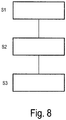
- a method for monitoring a clearance of such a disc brake comprises the method steps (S1) forming current value pairs from current brake pressure values and recorded current signal values of the wear sensor during a braking process; (S2) comparing the current value pairs formed with previously stored reference values; and (S3) evaluating the comparison and outputting messages for monitoring the clearance.
- thermal influences are included by means of temperature detection, with further parameters of the disc brake being learned and included, whereby the reliability of the messages is increased.
- control device of the clearance monitoring device is designed to detect a current signal value of the wear sensor with a detection unit.
- the detection unit can detect a change over time in the current signal value of the wear sensor. This is particularly advantageous when the wear sensor is adjusted. A change can be recorded immediately.
- a further embodiment provides that the control device of the clearance monitoring device is provided with a comparison unit to form current value pairs from current brake pressure values and detected current signal values of the wear sensor and to compare the current value pairs with stored reference values.
- the reference values can be, for example, pressure-travel characteristics of a brake cylinder of the associated disc brake. Particularly beneficial it is when these pressure-travel characteristics can be taught in when new, which enables a different design.
- the current brake pressure values can come from the brake control device and / or be output values from at least one other sensor.
- the brake control device can have corresponding table and / or characteristic curve values. Of course, an existing pressure sensor or force sensor can also be used.
- the stored reference values are also stored in the brake control device.
- the stored reference values can be stored in a storage unit of the control device. It is advantageous here if these are the taught-in characteristic curve values and other taught-in values, since greater accuracy is then possible.
- control device of the clearance monitoring device has an evaluation unit for evaluating the results of the comparison unit.
- the recorded values can be differentiated on the basis of trends and secondary conditions. Warnings and indications can be given in this regard exactly.
- the clearance monitoring device comprises a reporting unit which, based on the evaluation of the evaluation unit, reports reports on the status of the clearance monitoring acoustically, visually, haptically and / or alphanumerically.
- a driver of the vehicle can be made aware of problems or compliance with maintenance deadlines or visiting a workshop in good time.
- the messages can be saved and accessed by maintenance personnel.
- the control device of the clearance monitoring device can be part of the brake control device, which means that there is no significant additional space requirement on the disc brake.
- step (S1) forming current value pairs (p / U)
- the current brake pressure values are supplied by the brake control device and / or an additional sensor.
- the brake pressure values are already available in the brake control device, so no additional sensors that require space need to be installed.
- process step (S3) evaluation a previously determinable, nominal and due to wear increased clearance with readjustment is determined if a current value pair corresponds to a stored value pair that is assigned to a correct clearance, and the subsequent value pair a change in the recorded current signal value of the wear sensor, but does not have a sharp increase in brake pressure.
- a previously definable, nominal release play can be determined to be undershot if the brake pressure of a current value pair is less than the brake pressure assigned to a previously definable, correct release play, and the subsequent value pair exhibits no change in the detected current signal value of the wear sensor, but a sharp increase in the brake pressure or a change in the detected current signal value of the wear sensor, but no sharp increase in the brake pressure.
- a further increase in reliability is achieved in that in method step (S3) evaluation, a warning or a warning signal is output only after a certain number of braking operations.
- a friction point can be determined by comparing the current value pairs with stored value pairs when a current value pair of the current value pairs that are compared with stored value pairs has a sharp increase in the brake pressure.
- the current ventilation clearance can be recorded and monitored continuously or with sufficient frequency.
- the clearance can be monitored and recorded specifically for each brake.
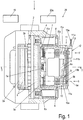
- FIG. 1 shows a schematic partial sectional view of an embodiment of a disk brake 1 according to the invention with a clearance monitoring device 20.
- FIG. 11 is a schematic sectional view of the embodiment along the line II-II of FIG Fig. 1 shown in a variant.
- the disc brake 1 has a brake disc 2 with a brake disc axis 2a.
- the brake disk 2 is overlapped by a brake caliper 4, designed here as a floating caliper.
- a brake lining 3, each with a brake lining carrier 3a, is arranged on both sides of the brake disc 2.
- the one in the Figures 1 and 2 Brake lining 3 located on the left side of the brake disc 2 is called the reaction-side brake lining 3 and the brake lining 3 arranged on the right side of the brake disc 2 is called the application-side brake lining 3.
- the disc brake 1 is designed as a two-piston brake with two spindle units 5 and 5 '.
- Each spindle unit 5, 5 ' has a threaded punch 6, 6' which is designed as a hollow shaft with an external thread.
- an adjusting device 10 is used, which will be discussed in more detail below.
- One axis of this spindle unit 5 is therefore referred to as the adjuster axis 5a.
- the adjustment device 10 is provided with an adjuster shaft 5b, which cooperates with the threaded punch 6 in a rotationally fixed manner.
- the other spindle unit 5 ' has an axis, which is referred to as the driver axis 5'a, and a driver shaft 5'b which is inserted in the threaded punch 6' of the other spindle unit 5 'and is in a rotationally fixed connection with the threaded punch 6' .
- the brake lining carrier 3a on the application side is connected to the spindle units 5, 5 'via pressure pieces 6a, 6'a which are arranged at the ends of the threaded rams 6, 6'.
- the other, reaction-side brake lining carrier 3a is fixed on the other side of the brake disc in the brake caliper 4.
- the threaded punches 6, 6 ' are each arranged in a traverse 7, which is also referred to as a bridge, with their external threads so as to be rotatable in threaded bores of the traverse 7.
- the thread is designed here with a pitch in the area of self-locking.
- the rotational movement of the threaded punches 6, 6 'in the traverse 7 changes the axial position of the threaded punches 6, 6' relative to the traverse 7.
- the term axial position here is a position of the threaded punches 6, 6 'in the axial direction of the brake disc axis 2a and the Axes 5a, 5'a meant.
- the axes 5a, 5'a here run parallel to the brake disk axis 2a.
- the brake lever 8 has a lever body 8d which interacts with the cross member 7 via bearing sections.
- the cross member 7 can be adjusted in the direction of the brake disk axis 2a by the brake lever 8.
- a movement towards the brake disc 2 is referred to as an application movement, and a movement in the opposite direction is referred to as a release movement.
- a return spring 7a which is not explained further, is received in the center of the crossbeam 7 in a corresponding recess on the lining-side side of the crossbeam 7 and is supported on the brake caliper 4.
- the return spring 7a By means of the return spring 7a, the cross member 7 is moved into the in Fig. 1 and Fig. 2 The shown released position of the disc brake 1 is adjusted.
- a distance between the brake pads 3 and the brake disc 2 in the released position is referred to as the clearance.
- this clearance becomes larger. If this is not compensated for, the disc brake 1 cannot achieve its peak performance, since an actuation stroke of the actuation mechanism, ie here the actuation stroke or a pivot angle of the brake lever 8, is increased.
- the disc brake 1 can have different power drives.
- the brake lever 8 is actuated pneumatically here, for example.
- the brake lever 8 has an arm 8b which is connected to the lever body 8d ( Fig. 2 ).
- a force introduction section 8c which interacts with a force source, for example a pneumatic cylinder.
- the adjustment device 10 is designed to adjust for wear of a previously determined air gap, which is referred to as the nominal air gap.
- the term "adjustment" is to be understood as a reduction in the air gap.
- the previously determined clearance is determined by the geometry of the disc brake 1 and has a so-called constructive clearance. In other words, the adjustment device 10 reduces an existing clearance if this is too large in relation to the previously established clearance.
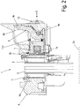
- the adjusting device 10 is arranged on the one spindle unit 5 coaxially to the latter, to its threaded punch 6 and to the adjusting axis 5a.
- the adjusting device 10 is mounted with its application-side end in the brake caliper 4 in a manner not explained in detail. To do this, refer to the document DE 10 2004 037 771 A1 referenced.
- a synchronizing wheel 11a of a synchronizing device 11 is attached non-rotatably to the end of the adjuster shaft 5b on the application side.
- the adjuster shaft 5b is operatively connected to the driver shaft 5'b of a driver device via the synchronizer device 11, which will be described below.
- the driver device with the driver shaft 5'b is arranged coaxially to the other spindle unit 5', to its threaded punch 6 'and to the driver axis 5'a.
- a synchronizing wheel 11'a of the synchronizing device 11 is attached in a rotationally fixed manner in the application-side end region of the driver shaft 5'b.
- the end of the drive shaft on the application side 5'b is coupled here to a wear sensor 12, which is arranged in a hood-shaped housing over the application-side end of the driver shaft 5'b on the brake caliper 4.
- the wear sensor 12 is non-rotatably coupled to the threaded punch 6 'via the driver shaft 5b.
- a pick-up element of the wear sensor can be, for example, an angle sensor, for example a potentiometer. It detects the angular position of the threaded punch 6 'around the driver axis 5'a. The evaluation of this angular position allows a conclusion to be drawn about the state of wear of the brake linings 3 and the brake disc 2, because the threaded punch 6 'is coupled to the threaded punch 6 via the driver shaft 5'b and thus by the synchronizer 11 explained in more detail below.
- an angle sensor for example a potentiometer
- the wear sensor 12 is used to detect an adjustment path, ie the state of wear, and is connected to a brake control device 19 via a connecting line 13a provided with a plug connector 13 (electrically or optically conductive), which can, among other things, evaluate the measured value detected by the wear sensor 12, connected.
- a plug connector 13 electrically or optically conductive
- the wear sensor 12 is also connected to a control device 20a of the clearance monitoring device 20. This is explained in detail below.
- Usual pneumatic disc brakes 1 such as in the DE 197 29 024 C1 described, have the adjustment device 10 together with the driver device as integrated, automatically operating wear adjustment devices. By mechanically adjusting the position of the threaded spindles 6, 6 'in the traverse 7, previous wear of the friction partner brake linings 3 and brake disc 2 is compensated for and the previously determined clearance is maintained.
- a drive for the adjustment movement of the adjustment device 10 is provided by a secondary function of the brake lever 8 with an output finger 8a (or several).
- the brake lever 8 is e.g. actuated by a brake cylinder (pneumatic, hydraulic, electric).
- the adjustment device 10 interacts with the brake lever 8 via a drive 9.
- the drive 9 comprises an actuator, which is designed as an output finger 8a connected to the brake lever 8, and a shift fork finger 10b of a drive element 10a of the adjustment device 10.
- the drive 9 is used in conjunction with the Figures 3 and 4 described in more detail.
- a one-way clutch of the adjustment device 10 is actuated, for example, which is coupled to the adjustment shaft 5b via a slip clutch.
- a detailed description of the function of the adjusting device 10 can be found in the document DE 10 2004 037 771 A1 refer to.
- the adjuster shaft 5b of the adjuster device 10 and the driver shaft 5'b of the driver device are coupled by the synchronizer 11 in such a way that a twisting movement of the threaded ram 6 about the night adjuster axis 5a causes a corresponding twisting movement of the threaded ram 6 'around the driver axis 5'a and vice versa.
- the synchronizer 11 is in the in Fig.
- the synchronizer 11 comprises the synchronizer 11a, which is coupled to the threaded punch 6 of one spindle unit 5 and to the adjuster shaft 5b of the adjuster 10, the other synchronizer 11'a, which is coupled to the Threaded punch 6 'of the other spindle unit 5' and is coupled to the driver shaft 5'b of the driver device, and a synchronizing means 11b with which the synchronizing wheels 11a and 11'a are coupled.
- the synchronizing means 11b is a traction means, in the present example a chain.
- the synchronous wheels 11a, 11'a are designed as chain wheels. This ensures a synchronous movement of the threaded punches 6, 6 'of the spindle units 5 and 5' during wear adjustment processes (driven by the adjuster shaft 5b of the adjuster device 10) and adjustments during maintenance work, e.g. changing the lining (manual drive e.g. via an actuating end of the adjuster shaft 5b of the adjuster device 10 which is not shown, but is easy to imagine) guaranteed.
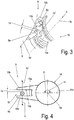
- FIG. 13 is an enlarged partial perspective view of the drive 9 of the adjusting device 10 of the exemplary embodiment according to FIG Fig. 1 shown.
- Fig. 4 shows a schematic plan view of the drive 9.
- the lever body 8d of the brake lever 8 is only indicated schematically, the adjusting device 10 with the adjusting axis 5a of the one spindle unit 5 being partially shown on the right-hand side.
- two output fingers 8a are attached here in the form of a pin or rod, which are in engagement with three shift fork fingers 10b of the drive element 10a of the adjustment device 10, the output fingers 8a each being arranged here in a gap 15 between two shift fork fingers 10b.
- Fig. 4 shows in plan view the arrangement of an output finger 8a in the gap 15 between two shift fork fingers 10b.
- the brake lever axis 8e about which the brake lever 8 can be pivoted, runs at right angles to the adjuster axis 5a (see also Fig. 2 ).
- a pivoting movement of the brake lever 8 then leads to a pivoting movement of the output fingers 8a, which in FIG Fig. 4 in an upward direction in the Fig. 4 (indicated by an arrow tightening hz) or downwards (indicated by an arrow releasing hl), this pivoting movement being transmitted to the shift fork fingers 10b and thus to the drive element 10a of the adjustment device 10.
- a play or idle travel 14 is provided between an actuating contour of the output finger 8a and a shift fork wall 15b of the shift fork finger 10b of the drive element 10a of the adjustment device 10.
- this idle travel represents the structural clearance of the disc brake 1.
- the adjustment device 10a is only actuated after the crossbeam 7 has pivoted the brake lever 8 when the disc brake 1 is applied, ie when the brake is actuated has been shifted to the brake disk 2 by a greater distance than the structural clearance.
- the design clearance is always determined by the idle travel 14 in the kinematic chain between the brake lever 8 and the one-way clutch of the adjustment device 10, the one-way clutch with the drive element 10a connected is.
- this idle travel 14 is first traversed in the direction of clamping hz, with no transfer of motion via the shift fork fingers 10b to the adjustment device 10.
- the brake lever 8 When the disc brake 1 is released, the brake lever 8 is pivoted back, with the output finger 8a being moved in the direction of release hl. In doing so, it comes into contact with the other shift fork wall 15a and thus pivots the drive element 10a in a pivot nl in the counterclockwise direction. Since the drive element 10a is coupled to the one-way clutch of the adjusting device 10, this movement is not transmitted to the night adjuster shaft 5b (this would then increase the clearance, which is not wanted).
- the readjustment or adjustment movement for reducing the clearance, which the readjustment shaft 5b performs, is transmitted via the synchronizer 11, as described above, to the driver shaft 5'b and also to the wear sensor 12.
- the wear sensor 12 generates, depending on the angular position of the driver shaft 5'b, an electrical signal (analog or digital) proportional to the angular position, which is used in an electrical / electronic device, for example in the brake control unit 19, as a measure of the wear on the brake linings 3 and also the Brake disc 2 of the disc brake 1 is evaluated for the continuous detection of the wear of the friction partners (brake pads 3 and brake disc 2).
- the adjustment (extension, readjustment) of the threaded spindles 6, 6 ′, which progresses with wear, can thus be recorded by measurement.
- This electrical / electronic device is based e.g. on a potentiometric measurement of the adjustment path, i.e. the angle of rotation, the threaded spindles 6, 6 ', which is integrated in each wheel brake of an associated vehicle.
- the measured values are monitored for a specific wheel in an evaluation unit and when a specified wear value or limit value is reached (corresponding to the extended or readjusted state of the threaded spindles 6, 6 ') a message is issued, e.g. an acoustic and / or visual warning signal.
- the device 20 comprises a control device 20a ( Fig. 1 ), which is described in more detail below.
- the control device 20a is connected to the wear sensor 12 and the brake control unit 19 coupled.
- the control device 20a uses signals from the wear sensor 12 and the brake control device 19.
- Fig. 5 shows a schematic diagram of a pressure-travel characteristic.
- Figure 5a represents a schematic diagram of a sensor signal.
- a brake pressure p of the application device of the disc brake 1 is shown on an ordinate over a lever travel h (abscissa).
- the brake pressure p can be, for example, the air pressure of a pneumatic cylinder and / or hydraulic cylinder or the application force of an electromotive brake actuation.
- the lever path h is to be understood as a path of the brake lever 8.
- Figure 5a shows with the same abscissa the lever path h as in Fig. 5 shown.
- a signal value U of a sensor signal 17 of the wear sensor 12 is plotted here over the lever travel h.
- the wear sensor 12 has a potentiometer as a pick-up element, ie an electrical resistance which is variable due to the pivoting of the driver shaft 5'b described above and which has a constant electrical voltage applied to it.
- the signal value U is an electrical voltage which can be tapped off at the pickup element and is proportional to the pivoting of the driver shaft 5'b. That is to say, the signal value U, as an electrical voltage, is proportional to an adjustment of the adjustment device 10. The signal value U only changes when an adjustment takes place.
- the curve of an exemplary pressure (force) displacement characteristic curve of a brake for example the disk brake 1, in FIG Fig. 5 specified.
- the brake cylinder interacts with the brake lever 8.
- Actuation of the application device comprises application and release.
- the brake cylinder and brake lever 8 are in the position shown in FIG. 1 by the internal return spring 7a Fig. 1 , 2 shown starting position or released position.
- a piston rod (not shown) moves in cooperation with the force introduction section 8c ( Fig. 2 ) the brake lever 8 and this the application elements (Traverse 7 with the threaded spindles 6, 6 ') in the brake caliper 4.
- the output finger 8a of the brake lever 8 touches the shift fork finger 10b of the drive element 10a with the one-way clutch of the adjustment device 10. This is the case with a lever travel h 0 .
- the brake pressure p rises in the area of bridging the clearance up to the lever travel h 0 with a relatively small slope of the curve 16.
- the clearance is bridged in this area.
- the clearance thus corresponds to the lever path h from the zero point to the lever path h 0 .
- the curve 16 of the brake pressure p intersects a parallel to the ordinate which runs through the lever travel h 0 .
- the curve 16 is assigned a brake pressure p 0 .
- the term “friction point” is the point at which the brake linings 3 rest on the brake disk 2 of the disk brake 1.
- a further application (application section 16a) then brings about a braking process or braking by pressing the brake linings 3 with increasing force against the brake disc 2, the brake pressure p increasing sharply in an application section 16a. Releasing the application device (by reducing the brake pressure p) reverses the process described above.
- Fig. 6 shows a schematic diagram of a sensor characteristic curve 18.
- a signal value U for example an electrical voltage
- the total wear GV relates to the friction partners brake linings 3 and brake disc 2.
- an initial value is given as a signal value Ua.
- the sensor characteristic 18 is linear here and extends with a specific gradient from the initial value Ua to an end value Ub, to which a total wear GVa is assigned. In the event of total wear GVa, at least the brake linings 3 must be replaced, and a wear limit has been reached.
- the signal value Ua has a voltage of approx. 0.8 V as an output value, for example.
- the total wear GVa is reached at a voltage of approx. 3.5 V at the signal value Ub.
- the signal value Uc which is approx. 4 V.
- other voltage values or also current values can be used as signal values U.
- Figure 5a the associated sensor signal 17, which is constant when the disc brake 1 is idle, i.e. when the application device is not actuated, and when actuated until the structural clearance is overcome until the lever travel h 0 is reached.
- This is in Figure 5a indicated by the signal value U 0 .
- the signal value U 0 thus corresponds to a readjustment value that originates from the most recent readjustment or forms an initial value in the case of new brake linings 3.
- a further movement of the output finger 8a with increasing brake pressure p in the brake section 16a is applied to the shift fork finger 10b of the drive element 10a of the adjustment device 10 ( Fig. 3, 4 ), but an overload clutch present in the adjustment device 10 responds because the brake linings 3 are already in contact with the brake disc 2.
- the drive element 10a then performs a movement relative to the stationary adjuster shaft 5b. There is therefore no readjustment.
- the adjuster shaft 5b and the driver shaft 5'b coupled to it via the synchronizer 11 with the wear sensor 12 coupled to it are not adjusted.
- the sensor signal 17 is therefore not changed and remains constant at the signal value U 0 .
- Fig. 5 also the cases in which the current friction point does not coincide with the target friction point at lever travel h 0 .
- the case is considered in which the clearance has increased due to wear of the brake linings 3 due to previous braking processes.
- the current friction point has shifted to a larger value of the lever feed path h.
- This current friction point is indicated here as friction point R1 with a lever travel h1.
- the lever path h1 is greater than the previous lever path h 0 , which is a result is that due to the wear of the brake linings 3, a larger clearance has to be bridged, namely the structural clearance up to the lever travel h 0 and then the clearance caused by the wear up to the lever travel h 1 .
- this friction point R 1 is reached with the associated brake pressure p 1 , the brake pressure p rises sharply in an application section 16b, which extends to the right in the Fig. 5 has relocated.
- the signal value Uo which is assigned to the lever value h 0 , changes to the new signal value U 1 at the lever value h 1 .
- U 1 is greater than U 0 , but the reverse can of course also be possible in another embodiment.
- the signal value U 1 now corresponds to the current wear of brake linings 3 and brake disc 2. This signal value U 1 remains constant until it is changed by a subsequent adjustment. This shows a constant signal section 17b from the lever value h 1 in Figure 5a .
- the drive element 10a of the adjustment device 10 can be operated with its shift fork finger 10b ( Fig. 3, 4 ), e.g. as a result of an error, a rotary movement (in Fig. 4 in pivoting nl counterclockwise) against their functionally defined direction of rotation pivoting nz (that is, against the locking direction of the one-way clutch coupled to the drive element 10a).
- the wear sensor 12 is also activated when the shift fork finger 10b comes into contact with the output finger 8a ( Fig. 3, 4 ) at lever travel h 2 correspondingly earlier pivoted and changes the signal value U 0 already at the shorter lever travel h 2 in a signal section 17'a to the constant signal section 17'b already occurring at lever travel h 0 .
- This is in Figure 5a with dashed-double-dotted lines for 17'a and 17'b.
- the brake pressure values p 0 , p 1 , p 2 (and of course also others) are available which have been input into the brake cylinder at the respective lever value h 0 , h 1 , h 2 .
- a simplified, similar characteristic 16 is shown in Fig. 5 shown.
- the term "sensor response signal” includes signal value U of sensor signal 17 of wear sensor 12 including the time behavior of signal value U zu understand. This is explained below.
- the pair of values p / u consists of the brake pressure p 0 and the previously constant signal value U 0 of the wear sensor 12.
- the sensor response signal is the constant signal value U 0 .
- the nominal clearance is undershot (at the brake pressure p 0 at the friction point R 0 at the lever travel h 0 ), with the brake pressure p 2 consequently at the beginning of the change in the signal value U 0 of the sensor signal 17 of the wear sensor 12 is less than the nominal brake pressure p 0 (application pressure).
- the assigned value pair p / u here has the brake pressure p 2 and the sensor response value U ⁇ Uo.
- This difference between the nominal brake pressure p 0 (application pressure) and the current brake pressure p when the sensor response signal occurs before the nominal brake pressure p 0 is reached can be used as a basis for setting a warning signal or another measure.
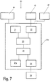
- Fig. 7 a schematic block diagram of the clearance monitoring device 20.
- the clearance monitoring device 20 is provided for each wheel brake, e.g. for a three-axle commercial vehicle for six wheel brakes.
- the clearance monitoring device 20 comprises the control device 20a, the wear sensor 12 and a reporting unit 26.
- the brake control device 19 is also assigned to which the control device 20a is connected.
- corresponding sensors can of course also be connected to the control device 20a.
- These sensors can, for example, be a brake pedal sensor for detecting braking, a pressure and / or force sensor for detecting the application force or the brake pressure p, a lever travel sensor or a brake cylinder piston travel sensor to detect the lever travel h.
- the characteristic of the brake cylinder and / or the disc brake 1 is a pressure-displacement characteristic, such as the characteristic 16 in FIG Fig. 5 , stored in the brake control device 19 or in a special storage device, for example in the control device 20a.
- a temperature detection 27 is shown for the detection of additional variables, which may be used by the control device 20a for evaluating measured values and derived variables.
- This can e.g. be a temperature sensor on each wheel brake of an associated vehicle, which is correspondingly connected to the control device 20a.
- connections to the control device 20a can be electrical or optical transmission links; wireless connections are of course also possible, for example from each wheel brake of a vehicle to a central reporting unit 26.
- control device 20a comprises a memory unit 21, a recognition unit 22, a comparison unit 23, an evaluation unit 24 and an output unit 25.
- the storage unit 21 is used to store, among other things previously definable values, e.g. Table values and / or characteristics of the respective brake cylinder and wear sensor 12.
- the pressure-displacement characteristic of the respective brake cylinder can, however, also be written into the memory unit 21 by what is known as independent learning. This can e.g. when the disc brake 1 is new. The same also applies to the characteristic curves of the wear sensors 12.
- Other values can also be stored in the memory unit 21 as references, limit values, etc.
- the storage unit 21 is connected to the comparison unit 23.
- the storage unit 21 also serves to store the signal values detected by the wear sensor 12, either through a direct connection (not shown) to this or e.g. via the brake control unit 19.
- the detection unit 22 is connected to the wear sensor 12. It detects the current signal value U of the sensor signal 17 of the wear sensor 12. In addition, the detection unit 22 is connected to the comparison unit 23 and provides the comparison unit 23 with the detected signal value U in a corresponding form, for example as a digital signal.
- the comparison unit 23 forms current value pairs p / U with current brake pressure values p from the brake control device 19 or from other sensors (not shown) and with the current signal values U supplied by the detection unit 22. This compares the comparison unit 23 with the table values or characteristic curve values from the storage unit 21 and / or from the brake control device 19. The comparison unit 23 supplies its comparison results to the evaluation unit 24 to which it is connected.
- the evaluation unit 24 evaluates the results obtained from the comparison unit 23, it also making use of the memory unit 21 (which is not shown). As a function of the evaluation, the evaluation unit 24 activates the output unit 25 connected to it by transferring values, warnings, and information with corresponding instructions for output to it. In addition, the evaluation unit 24 is connected to a further memory unit 21a, in which e.g. the current signal value U can be saved temporarily or for further use. Of course, other values can also be stored and / or stored in the storage unit 21a.
- the output unit 25 prepares the information received from the evaluation unit 24 for display or notification and transmits this in a suitable form to the notification unit 26.
- the release play monitoring device 20 is activated.
- the current value pairs p / U formed by the comparison unit 23 are compared with the value pairs stored in the memory unit 21.
- the brake pressure p increases, it is monitored whether a change in the constant signal value U of the wear sensor 12 occurs until the nominal brake pressure p 0 is reached. If this is the case (U> Uo), the evaluation unit 24 issues a warning to the output unit 25 for acoustic, optical, haptic and / or alphanumeric notification by the reporting unit 26 that the nominal clearance has not been reached.
- the evaluation unit 24 informs the reporting unit 25 that readjustment is taking place.
- the adjustment can also be evaluated in such a way that the adjustment is small, normal or large.
- Fig. 8 shows a flowchart of an exemplary embodiment of a method according to the invention for monitoring clearance with the above-described clearance monitoring device.
- a first method step S1 the current value pairs p / U are formed during a braking process, the signal values U being recorded.
- a second method step S2 the current value pairs p / U are compared with the value pairs stored in the memory unit 21.
- the control device 20a is connected to a temperature detector 272.
- the temperature detection 27 can, for example, be a separate temperature sensor on the Be disc brake 1 or a temperature value that the brake control unit 19 supplies.
- the output of a warning or a warning signal can only be set outside the tolerance after a certain number of measured values or monitoring (current value pairs p / U).
- a message positive, negative or neutral
- the clearance monitoring device 20 While the detection and evaluation of the value pairs p / U can take place at any desired operating time of the disc brake 1 by the clearance monitoring device 20, different procedures are of course possible. Both the time and the frequency of the clearance monitoring can be determined depending on the vehicle type or use. E.g. the clearance monitoring can be carried out when the vehicle is at a standstill (by initiating an automatic application of the brake or by the signaling unit with a request to the driver) or while driving. Release clearance monitoring can also only take place after a certain number of braking operations or continuously.
- the clearance monitoring device 20 is described as an example for a specific type of disc brakes 1.
- the clearance monitoring device 20 can thus also be used for other types of adjustment device 10, drive 9 and electronic wear sensors, since the functional principles also apply here.
- drum brakes can also be used with drum brakes, as some of these are equipped with electronic wear detection and control with a brake control (EBS) and obey the same principles with regard to the adjustment principle.
- EBS brake control
- the clearance monitoring device 20 provided for each wheel brake is arranged at a central location on the vehicle, for example at or in the common brake control device 19.
- the clearance monitoring devices 20 can also be part of the software of the brake control device 19.
Landscapes
- Engineering & Computer Science (AREA)
- General Engineering & Computer Science (AREA)
- Mechanical Engineering (AREA)
- Physics & Mathematics (AREA)
- Health & Medical Sciences (AREA)
- Life Sciences & Earth Sciences (AREA)
- Chemical & Material Sciences (AREA)
- Analytical Chemistry (AREA)
- Biochemistry (AREA)
- General Health & Medical Sciences (AREA)
- General Physics & Mathematics (AREA)
- Immunology (AREA)
- Pathology (AREA)
- Braking Arrangements (AREA)
- Regulating Braking Force (AREA)
Applications Claiming Priority (2)
| Application Number | Priority Date | Filing Date | Title |
|---|---|---|---|
| DE102013100786.4A DE102013100786A1 (de) | 2013-01-25 | 2013-01-25 | Scheibenbremse mit einer Lüftspielüberwachungsvorrichtung und Verfahren zur Lüftspielüberwachung |
| PCT/EP2014/051401 WO2014114747A2 (de) | 2013-01-25 | 2014-01-24 | Scheibenbremse mit einer lüftspielüberwachungsvorrichtung, und verfahren zur lüftspielüberwachung |
Publications (2)
| Publication Number | Publication Date |
|---|---|
| EP2948690A2 EP2948690A2 (de) | 2015-12-02 |
| EP2948690B1 true EP2948690B1 (de) | 2020-11-11 |
Family
ID=50029019
Family Applications (1)
| Application Number | Title | Priority Date | Filing Date |
|---|---|---|---|
| EP14701727.1A Active EP2948690B1 (de) | 2013-01-25 | 2014-01-24 | Scheibenbremse mit einer lüftspielüberwachungsvorrichtung, und verfahren zur lüftspielüberwachung |
Country Status (10)
Families Citing this family (27)
| Publication number | Priority date | Publication date | Assignee | Title |
|---|---|---|---|---|
| DE102015100322A1 (de) * | 2015-01-12 | 2016-07-14 | Bpw Bergische Achsen Kg | Scheibenbremse sowie Antriebselement einer Nachstelleinrichtung einer Scheibenbremse |
| DE102015001152A1 (de) * | 2015-02-02 | 2016-08-04 | Wabco Europe Bvba | Verfahren zur Überwachung einer Bremse für Kraftfahrzeuge, Bremssystem zur Durchführung des Verfahrens sowie Kraftfahrzeug mit einem solchen |
| US10570974B2 (en) * | 2015-04-17 | 2020-02-25 | Goodrich Corporation | Brake position and wear detection systems and methods |
| DE102016001577A1 (de) * | 2016-02-11 | 2017-08-17 | Wabco Europe Bvba | Verfahren zur Lüftspielerkennung bei einer Bremse eines Kraftfahrzeugs, insbesondere Nutzkraftfahrzeugs, Controller sowie Bremse mit selbigem |
| EP3251908B1 (en) * | 2016-06-03 | 2021-01-20 | Meritor Heavy Vehicle Braking Systems (UK) Limited | Brake system and method of control with air gap estimation |
| CN105937569B (zh) * | 2016-06-17 | 2018-07-10 | 安徽机电职业技术学院 | 一种可调节式刹车片 |
| US10493962B2 (en) | 2017-07-24 | 2019-12-03 | Goodrich Corporation | Brake position system |
| US10800386B2 (en) | 2017-07-24 | 2020-10-13 | Goodrich Corporation | Brake position system |
| US11125293B2 (en) * | 2017-10-16 | 2021-09-21 | Wabco Europe Bvba | Brake device for a utility vehicle |
| US10731720B2 (en) | 2018-01-26 | 2020-08-04 | Rivian Ip Holdings, Llc | Methods, systems, and media for non-contact brake pad wear determination |
| DE102018210232A1 (de) * | 2018-06-22 | 2019-12-24 | Robert Bosch Gmbh | Verfahren zum Ansteuern einer elektromechanischen Bremsvorrichtung in einem Fahrzeug |
| DE102018117574A1 (de) * | 2018-07-20 | 2020-01-23 | Knorr-Bremse Systeme für Nutzfahrzeuge GmbH | Scheibenbremse mit einem elektrischen Aktuator und Verfahren zum Einstellen eines definierten Lüftspiels einer Scheibenbremse |
| DE102019100481A1 (de) | 2019-01-10 | 2020-07-16 | Wabco Europe Bvba | Verfahren zum Einstellen eines Lüftspiels einer elektromechanischen Bremse sowie betreffende Bremse und Steuergerät |
| KR102727459B1 (ko) * | 2019-08-27 | 2024-11-07 | 현대모비스 주식회사 | 브레이크 패드 마모 상태 모니터링 장치 |
| CN110790103B (zh) * | 2019-11-11 | 2021-06-01 | 苏州科瞬电磁技术有限公司 | 一种测试方法 |
| IT202000021220A1 (it) * | 2020-09-08 | 2022-03-08 | Alessio VARDIERO | Sistema di frenatura e metodo |
| CN112503121B (zh) * | 2020-12-29 | 2022-03-15 | 焦作市虹桥制动器股份有限公司 | 一种电液踏面制动器 |
| WO2022194427A1 (en) * | 2021-03-16 | 2022-09-22 | Eaton Intelligent Power Limited | Clutch system with wear indicator |
| DE102021203735A1 (de) | 2021-04-15 | 2022-10-20 | Continental Automotive Technologies GmbH | Verfahren zum Bestimmen von Verschleißparametern eines Bremsbelags |
| CN114458708B (zh) * | 2021-08-25 | 2024-03-26 | 苏州麦哲轮汽车电子科技有限公司 | 一种汽车制动钳温度传感控制系统及控制方法 |
| KR102727166B1 (ko) * | 2021-12-27 | 2024-11-06 | 상신브레이크주식회사 | 브레이크 패드의 마모량을 검출하는 장치, 및 이를 구비하는 디스크 브레이크 |
| CN114368378B (zh) * | 2022-01-11 | 2022-10-14 | 中车大同电力机车有限公司 | 机车制动监测装置及方法 |
| DE102022116576A1 (de) * | 2022-07-04 | 2024-01-04 | Zf Cv Systems Global Gmbh | Verfahren zum Einstellen eines Anlegedrucks einer Fahrzeugbremse und betreffende Fahrzeugbremse |
| DE102022125261A1 (de) * | 2022-09-30 | 2024-04-04 | Knorr-Bremse Systeme für Nutzfahrzeuge GmbH | Scheibenbremse für ein Nutzfahrzeug |
| DE102023102526A1 (de) * | 2023-02-02 | 2024-08-08 | Knorr-Bremse Systeme für Nutzfahrzeuge GmbH | Scheibenbremse für ein Nutzfahrzeug |
| WO2025073033A1 (pt) * | 2023-10-05 | 2025-04-10 | Instituto Hercílio Randon | Método e dispositivo de monitoramento de estado de saúde em sistema de freio |
| CN118329419B (zh) * | 2024-04-26 | 2024-09-20 | 江苏方意摩擦材料股份有限公司 | 一种陶瓷型刹车片的高速刹停检测装置及检测方法 |
Family Cites Families (40)
| Publication number | Priority date | Publication date | Assignee | Title |
|---|---|---|---|---|
| US4937554A (en) * | 1989-05-22 | 1990-06-26 | Paccar Inc. | Electronic brake monitoring system and method |
| DE3930572A1 (de) * | 1989-09-13 | 1991-03-14 | Wabco Westinghouse Fahrzeug | Verfahren zur ueberschlaegigen ermittlung der mittleren temperatur eines bauteils einer bremseinrichtung |
| DE4017950A1 (de) | 1990-06-05 | 1991-12-12 | Wabco Westinghouse Fahrzeug | Bremsbetaetigungseinrichtung mit einer einrichtung zum nachstellen einer bremse |
| EP0567155B1 (de) | 1992-04-24 | 1996-03-27 | DEUTSCHE PERROT-BREMSE GmbH | Verschleissüberwachungsvorrichtung für eine Gleitsattel-Scheibenbremse |
| US5339069A (en) * | 1992-07-01 | 1994-08-16 | Tripen Enterprises Ltd. | Brake monitoring system |
| SE504466C2 (sv) * | 1995-06-08 | 1997-02-17 | Haldex Ab | Slitageindikeringsanordning för bromsbelägg |
| DE19600819A1 (de) * | 1996-01-11 | 1997-07-17 | Perrot Bremsen Gmbh | Verschleißüberwachungsvorrichtung |
| WO1997029297A1 (en) * | 1996-02-07 | 1997-08-14 | Lucas Industries Public Limited Company | Brake wear sensor |
| SE511562C2 (sv) * | 1997-04-28 | 1999-10-18 | Volvo Lastvagnar Ab | Justeranordning avseende förslitning av bromsbelägg |
| DE19729024C1 (de) | 1997-07-08 | 1999-01-28 | Knorr Bremse Systeme | Verschleißnachstellvorrichtung für Scheibenbremsen |
| DE19731696A1 (de) | 1997-07-23 | 1999-02-11 | Knorr Bremse Systeme | Verschleißnachstellvorrichtung für Scheibenbremsen und Verfahren zum Steuern der Vorrichtung |
| US20020126007A1 (en) * | 1998-11-30 | 2002-09-12 | Weant Bob R. | Brake monitoring system |
| JP2000234641A (ja) * | 1999-02-15 | 2000-08-29 | Toyota Motor Corp | 電動式ブレーキ装置 |
| DE19933962C2 (de) | 1999-07-20 | 2003-01-30 | Knorr Bremse Systeme | Vorrichtung und Verfahren zur Überwachung elektromechanischer Zuspannvorrichtung für Fahrzeugbremsen |
| US7600455B2 (en) * | 2000-08-14 | 2009-10-13 | Sd3, Llc | Logic control for fast-acting safety system |
| US6626269B2 (en) * | 2000-08-08 | 2003-09-30 | Delphi Technologies, Inc. | Zero drag disc brake with anti-knock-back device |
| US6581728B2 (en) * | 2001-02-08 | 2003-06-24 | Volvo Trucks North America, Inc. | Brake shoe proximity sensor |
| JP2003004075A (ja) * | 2001-06-21 | 2003-01-08 | Akebono Brake Ind Co Ltd | 車両用ブレーキ素子の寿命表示装置の修理方法 |
| CA2456242C (en) * | 2001-08-03 | 2011-03-15 | Spectra Products Inc. | Brake system |
| DE10138452B4 (de) | 2001-08-04 | 2014-07-17 | Wabco Gmbh | Verfahren zur Lüftspielnachstellung von Scheibenbremsen |
| US6637262B2 (en) * | 2001-11-02 | 2003-10-28 | Delphi Technologies, Inc. | Electrical wear sensor for disc brake |
| DE10305702B4 (de) * | 2002-02-13 | 2006-02-02 | Knorr-Bremse Systeme für Nutzfahrzeuge GmbH | Scheibenbremse mit elektromotorisch angetriebener Nachstellvorrichtung und Verfahren zur Steuerung einer Scheibenbremse |
| DE10214669B4 (de) | 2002-04-03 | 2014-01-23 | Knorr-Bremse Systeme für Schienenfahrzeuge GmbH | Verfahren und Vorrichtung zur Ansteuerung einer elektrisch betätigten Verschleißnachstelleinrichtung |
| SE526946C2 (sv) * | 2003-06-13 | 2005-11-22 | Haldex Brake Prod Ab | Sensor system |
| DE10356801B3 (de) * | 2003-12-04 | 2005-05-25 | Wabco Radbremsen Gmbh | Scheibenbremse und Überwachungseinrichtung für eine solche Scheibenbremse |
| DE10357374A1 (de) * | 2003-12-09 | 2005-07-14 | Knorr-Bremse Systeme für Nutzfahrzeuge GmbH | Scheibenbremse, insbesondere mit elektromotorischer Nachstellvorrichtung, und Verfahren zur Ansteuerung derartiger Scheibenbremsen |
| US20050212357A1 (en) * | 2004-03-23 | 2005-09-29 | Frank Adams | Brake monitoring and sensor system for sensing temperature and wear |
| DE102004030464A1 (de) * | 2004-06-24 | 2006-01-19 | Adam Opel Ag | Bremssystem mit EBS und "prefill"-Funktion sowie Verfahren zur elektronischen Bremsregelung |
| DE102004037771A1 (de) | 2004-08-04 | 2006-03-16 | Knorr-Bremse Systeme für Nutzfahrzeuge GmbH | Nachstellvorrichtung für eine pneumatisch betätigte Scheibenbremse |
| US7244003B2 (en) * | 2004-12-20 | 2007-07-17 | International Truck Intellectual Property Company, Llc | Vehicle onboard brake pad/lining wear estimators with temperature estimations |
| WO2010003244A1 (en) * | 2008-07-10 | 2010-01-14 | Nbs Innovative Solutions Ltd. | Vehicle brake monitoring system and method |
| DE102008035369A1 (de) * | 2008-07-30 | 2010-02-04 | Knorr-Bremse Systeme für Nutzfahrzeuge GmbH | Verfahren zum Festsetzen einer Nachstellvorrichtung an einer Scheibenbremse |
| DE102008035366A1 (de) * | 2008-07-30 | 2010-02-04 | Knorr-Bremse Systeme für Nutzfahrzeuge GmbH | Nachstellvorrichtung für eine Scheibenbremse |
| DE102008036034A1 (de) * | 2008-08-01 | 2010-02-18 | Knorr-Bremse Systeme für Nutzfahrzeuge GmbH | Nachstellvorrichtung für eine Scheibenbremse |
| DE102009014799A1 (de) * | 2009-03-25 | 2010-09-30 | Knorr-Bremse Systeme für Nutzfahrzeuge GmbH | Einrichtung zur Bremsbelagverschleißüberwachung einer Bremse |
| DE102009041951B4 (de) * | 2009-09-17 | 2020-04-02 | Knorr-Bremse Systeme für Nutzfahrzeuge GmbH | Messanordnung zur Zuspannkraftmessung einer Scheibenbremse und eine entsprechende Scheibenbremse |
| US8717159B2 (en) * | 2010-03-15 | 2014-05-06 | Jamie Bishop Todd | Vehicle brake monitoring system and method |
| DE202010003737U1 (de) * | 2010-03-17 | 2010-07-15 | Haldex Brake Products Ab | Sensoreinheit für eine Scheibenbremse |
| DE102010032515A1 (de) | 2010-07-28 | 2012-02-02 | Knorr-Bremse Systeme für Nutzfahrzeuge GmbH | Bremsverschleisssensor einer Scheibenbremse |
| DE102011100726A1 (de) | 2011-05-06 | 2012-11-08 | Man Truck & Bus Ag | Verfahren und Vorrichtung zum Überwachen des Bremsbelagverschleißes und Lüftspiels einer Betriebsbremse in Kraftfahrzeugen |
-
2013
- 2013-01-25 DE DE102013100786.4A patent/DE102013100786A1/de not_active Withdrawn
-
2014
- 2014-01-24 EP EP14701727.1A patent/EP2948690B1/de active Active
- 2014-01-24 KR KR1020157019964A patent/KR20150109371A/ko not_active Ceased
- 2014-01-24 RU RU2015135530A patent/RU2644839C2/ru not_active IP Right Cessation
- 2014-01-24 CN CN201480016426.4A patent/CN105190077B/zh not_active Expired - Fee Related
- 2014-01-24 JP JP2015554157A patent/JP6426623B2/ja not_active Expired - Fee Related
- 2014-01-24 MX MX2015009418A patent/MX358489B/es active IP Right Grant
- 2014-01-24 WO PCT/EP2014/051401 patent/WO2014114747A2/de active Application Filing
- 2014-01-24 BR BR112015016693A patent/BR112015016693A2/pt not_active Application Discontinuation
-
2015
- 2015-07-24 US US14/807,972 patent/US9958020B2/en active Active
Non-Patent Citations (1)
| Title |
|---|
| None * |
Also Published As
| Publication number | Publication date |
|---|---|
| JP6426623B2 (ja) | 2018-11-21 |
| US20150330470A1 (en) | 2015-11-19 |
| BR112015016693A2 (pt) | 2017-07-11 |
| MX2015009418A (es) | 2016-02-18 |
| CN105190077B (zh) | 2018-09-04 |
| EP2948690A2 (de) | 2015-12-02 |
| DE102013100786A1 (de) | 2014-07-31 |
| WO2014114747A3 (de) | 2014-09-18 |
| WO2014114747A2 (de) | 2014-07-31 |
| RU2644839C2 (ru) | 2018-02-14 |
| KR20150109371A (ko) | 2015-10-01 |
| CN105190077A (zh) | 2015-12-23 |
| MX358489B (es) | 2018-08-23 |
| JP2016504239A (ja) | 2016-02-12 |
| RU2015135530A (ru) | 2017-03-03 |
| US9958020B2 (en) | 2018-05-01 |
Similar Documents
| Publication | Publication Date | Title |
|---|---|---|
| EP2948690B1 (de) | Scheibenbremse mit einer lüftspielüberwachungsvorrichtung, und verfahren zur lüftspielüberwachung | |
| EP3359840B1 (de) | Elektrische verschleissnachstellvorrichtung einer scheibenbremse, eine entsprechende scheibenbremse und verfahren zum lüftspielmessen, -einstellen und verschleissmessen | |
| EP3019765B1 (de) | Verfahren zum ermitteln eines lüftspiels einer fahrzeugbremse und fahrzeugbremse mit einer vorrichtung zur ermittlung eines lüftspiels | |
| EP0189083B1 (de) | Einrichtung zum Messen und/oder Regeln des Verschleisses eines Bauteils | |
| DE69501956T2 (de) | Verschleissüberwachungseinrichtung für eine bremse | |
| EP0460376B1 (de) | Bremsbetätigungseinrichtung mit einer Einrichtung zum Nachstellen einer Bremse | |
| EP3898360B1 (de) | Elektromechanische bremsenanlage | |
| EP2310710B1 (de) | Kupplungsausrücksystem und verfahren zum betreiben eines kupplungsausrücksystems | |
| EP1979645B1 (de) | Verfahren zum anzeigen von verschleiss zumindest eines bremsbelags bei einer scheibenbremse mit elektromotorischem aktuator | |
| EP3717323B1 (de) | Scheibenbremse mit einer zustandsüberwachungsanordnung und verfahren zum zustandsüberwachen einer solchen scheibenbremse | |
| DE102009022891B3 (de) | Verfahren zur elektronischen Verschleißzustandsermittlung bei einer Ventilanordnung | |
| DE102008015873A1 (de) | Fahrzeug, insbesondere Schienenfahrzeug, mit einer Einrichtung zur Überwachung der Bremswirkung | |
| EP2831465B1 (de) | Verfahren zum bestimmen eines vorhandenen lüftspiels einer scheibenbremse und entsprechende scheibenbremse | |
| WO2005063535A1 (de) | Feststellbremse und verfahren zur steuerung derselben | |
| EP3698065B1 (de) | Bremsvorrichtung, insbesondere nutzfahrzeugscheibenbremse | |
| DE102013112527A1 (de) | Überwachungsvorrichtung und Fahrzeugbremse mit einer Überwachungsvorrichtung | |
| DE112019000912T5 (de) | Elektrische Bremse und Steuervorrichtung | |
| EP0460378B1 (de) | Bremsbetätigungseinrichtung mit einer Einrichtung zum Nachstellen einer Bremse | |
| DE102007021302B4 (de) | Verfahren und Vorrichtung zum Einstellen des von einer Reibungskupplung übertragenen Drehmoments | |
| EP0460377A2 (de) | Bremsbetätigungseinrichtung mit einer Einrichtung zum Nachstellen einer Bremse | |
| DE69705079T2 (de) | Mittel zur Erfassung des Zustandes einer Bremse | |
| EP1763465B1 (de) | Verfahren zum steuern einer elektronischen parkbremse | |
| DE102011002567A1 (de) | Scheibenbremse sowie Verfahren zur Ermittlung einer wirkenden Bremskraft oder eines wirkenden Bremsmoments | |
| EP3784921B1 (de) | Verfahren zur anzeige eines anstehenden bremsbelagswechsels einer fahrzeugbremse | |
| DE102017125262A1 (de) | Scheibenbremse mit einer Überwachungsvorrichtung für Verschleiss und Lüftspiel, und Verfahren zum Überwachen eines Verschleisszustands einer solchen Scheibenbremse |
Legal Events
| Date | Code | Title | Description |
|---|---|---|---|
| PUAI | Public reference made under article 153(3) epc to a published international application that has entered the european phase |
Free format text: ORIGINAL CODE: 0009012 |
|
| 17P | Request for examination filed |
Effective date: 20150825 |
|
| AK | Designated contracting states |
Kind code of ref document: A2 Designated state(s): AL AT BE BG CH CY CZ DE DK EE ES FI FR GB GR HR HU IE IS IT LI LT LU LV MC MK MT NL NO PL PT RO RS SE SI SK SM TR |
|
| AX | Request for extension of the european patent |
Extension state: BA ME |
|
| DAX | Request for extension of the european patent (deleted) | ||
| GRAP | Despatch of communication of intention to grant a patent |
Free format text: ORIGINAL CODE: EPIDOSNIGR1 |
|
| STAA | Information on the status of an ep patent application or granted ep patent |
Free format text: STATUS: GRANT OF PATENT IS INTENDED |
|
| INTG | Intention to grant announced |
Effective date: 20200527 |
|
| GRAS | Grant fee paid |
Free format text: ORIGINAL CODE: EPIDOSNIGR3 |
|
| GRAA | (expected) grant |
Free format text: ORIGINAL CODE: 0009210 |
|
| STAA | Information on the status of an ep patent application or granted ep patent |
Free format text: STATUS: THE PATENT HAS BEEN GRANTED |
|
| AK | Designated contracting states |
Kind code of ref document: B1 Designated state(s): AL AT BE BG CH CY CZ DE DK EE ES FI FR GB GR HR HU IE IS IT LI LT LU LV MC MK MT NL NO PL PT RO RS SE SI SK SM TR |
|
| REG | Reference to a national code |
Ref country code: GB Ref legal event code: FG4D Free format text: NOT ENGLISH |
|
| REG | Reference to a national code |
Ref country code: CH Ref legal event code: EP |
|
| REG | Reference to a national code |
Ref country code: AT Ref legal event code: REF Ref document number: 1333769 Country of ref document: AT Kind code of ref document: T Effective date: 20201115 |
|
| REG | Reference to a national code |
Ref country code: DE Ref legal event code: R096 Ref document number: 502014014983 Country of ref document: DE |
|
| REG | Reference to a national code |
Ref country code: IE Ref legal event code: FG4D Free format text: LANGUAGE OF EP DOCUMENT: GERMAN |
|
| REG | Reference to a national code |
Ref country code: NL Ref legal event code: MP Effective date: 20201111 |
|
| PG25 | Lapsed in a contracting state [announced via postgrant information from national office to epo] |
Ref country code: GR Free format text: LAPSE BECAUSE OF FAILURE TO SUBMIT A TRANSLATION OF THE DESCRIPTION OR TO PAY THE FEE WITHIN THE PRESCRIBED TIME-LIMIT Effective date: 20210212 Ref country code: FI Free format text: LAPSE BECAUSE OF FAILURE TO SUBMIT A TRANSLATION OF THE DESCRIPTION OR TO PAY THE FEE WITHIN THE PRESCRIBED TIME-LIMIT Effective date: 20201111 Ref country code: RS Free format text: LAPSE BECAUSE OF FAILURE TO SUBMIT A TRANSLATION OF THE DESCRIPTION OR TO PAY THE FEE WITHIN THE PRESCRIBED TIME-LIMIT Effective date: 20201111 Ref country code: NO Free format text: LAPSE BECAUSE OF FAILURE TO SUBMIT A TRANSLATION OF THE DESCRIPTION OR TO PAY THE FEE WITHIN THE PRESCRIBED TIME-LIMIT Effective date: 20210211 Ref country code: PT Free format text: LAPSE BECAUSE OF FAILURE TO SUBMIT A TRANSLATION OF THE DESCRIPTION OR TO PAY THE FEE WITHIN THE PRESCRIBED TIME-LIMIT Effective date: 20210311 |
|
| PG25 | Lapsed in a contracting state [announced via postgrant information from national office to epo] |
Ref country code: IS Free format text: LAPSE BECAUSE OF FAILURE TO SUBMIT A TRANSLATION OF THE DESCRIPTION OR TO PAY THE FEE WITHIN THE PRESCRIBED TIME-LIMIT Effective date: 20210311 Ref country code: PL Free format text: LAPSE BECAUSE OF FAILURE TO SUBMIT A TRANSLATION OF THE DESCRIPTION OR TO PAY THE FEE WITHIN THE PRESCRIBED TIME-LIMIT Effective date: 20201111 Ref country code: LV Free format text: LAPSE BECAUSE OF FAILURE TO SUBMIT A TRANSLATION OF THE DESCRIPTION OR TO PAY THE FEE WITHIN THE PRESCRIBED TIME-LIMIT Effective date: 20201111 Ref country code: SE Free format text: LAPSE BECAUSE OF FAILURE TO SUBMIT A TRANSLATION OF THE DESCRIPTION OR TO PAY THE FEE WITHIN THE PRESCRIBED TIME-LIMIT Effective date: 20201111 Ref country code: BG Free format text: LAPSE BECAUSE OF FAILURE TO SUBMIT A TRANSLATION OF THE DESCRIPTION OR TO PAY THE FEE WITHIN THE PRESCRIBED TIME-LIMIT Effective date: 20210211 |
|
| REG | Reference to a national code |
Ref country code: LT Ref legal event code: MG9D |
|
| PG25 | Lapsed in a contracting state [announced via postgrant information from national office to epo] |
Ref country code: HR Free format text: LAPSE BECAUSE OF FAILURE TO SUBMIT A TRANSLATION OF THE DESCRIPTION OR TO PAY THE FEE WITHIN THE PRESCRIBED TIME-LIMIT Effective date: 20201111 |
|
| PG25 | Lapsed in a contracting state [announced via postgrant information from national office to epo] |
Ref country code: SK Free format text: LAPSE BECAUSE OF FAILURE TO SUBMIT A TRANSLATION OF THE DESCRIPTION OR TO PAY THE FEE WITHIN THE PRESCRIBED TIME-LIMIT Effective date: 20201111 Ref country code: RO Free format text: LAPSE BECAUSE OF FAILURE TO SUBMIT A TRANSLATION OF THE DESCRIPTION OR TO PAY THE FEE WITHIN THE PRESCRIBED TIME-LIMIT Effective date: 20201111 Ref country code: LT Free format text: LAPSE BECAUSE OF FAILURE TO SUBMIT A TRANSLATION OF THE DESCRIPTION OR TO PAY THE FEE WITHIN THE PRESCRIBED TIME-LIMIT Effective date: 20201111 Ref country code: SM Free format text: LAPSE BECAUSE OF FAILURE TO SUBMIT A TRANSLATION OF THE DESCRIPTION OR TO PAY THE FEE WITHIN THE PRESCRIBED TIME-LIMIT Effective date: 20201111 Ref country code: EE Free format text: LAPSE BECAUSE OF FAILURE TO SUBMIT A TRANSLATION OF THE DESCRIPTION OR TO PAY THE FEE WITHIN THE PRESCRIBED TIME-LIMIT Effective date: 20201111 Ref country code: CZ Free format text: LAPSE BECAUSE OF FAILURE TO SUBMIT A TRANSLATION OF THE DESCRIPTION OR TO PAY THE FEE WITHIN THE PRESCRIBED TIME-LIMIT Effective date: 20201111 |
|
| REG | Reference to a national code |
Ref country code: DE Ref legal event code: R097 Ref document number: 502014014983 Country of ref document: DE |
|
| PG25 | Lapsed in a contracting state [announced via postgrant information from national office to epo] |
Ref country code: DK Free format text: LAPSE BECAUSE OF FAILURE TO SUBMIT A TRANSLATION OF THE DESCRIPTION OR TO PAY THE FEE WITHIN THE PRESCRIBED TIME-LIMIT Effective date: 20201111 Ref country code: MC Free format text: LAPSE BECAUSE OF FAILURE TO SUBMIT A TRANSLATION OF THE DESCRIPTION OR TO PAY THE FEE WITHIN THE PRESCRIBED TIME-LIMIT Effective date: 20201111 |
|
| REG | Reference to a national code |
Ref country code: CH Ref legal event code: PL |
|
| PLBE | No opposition filed within time limit |
Free format text: ORIGINAL CODE: 0009261 |
|
| STAA | Information on the status of an ep patent application or granted ep patent |
Free format text: STATUS: NO OPPOSITION FILED WITHIN TIME LIMIT |
|
| PG25 | Lapsed in a contracting state [announced via postgrant information from national office to epo] |
Ref country code: LU Free format text: LAPSE BECAUSE OF NON-PAYMENT OF DUE FEES Effective date: 20210124 |
|
| REG | Reference to a national code |
Ref country code: BE Ref legal event code: MM Effective date: 20210131 |
|
| 26N | No opposition filed |
Effective date: 20210812 |
|
| GBPC | Gb: european patent ceased through non-payment of renewal fee |
Effective date: 20210211 |
|
| PG25 | Lapsed in a contracting state [announced via postgrant information from national office to epo] |
Ref country code: IT Free format text: LAPSE BECAUSE OF FAILURE TO SUBMIT A TRANSLATION OF THE DESCRIPTION OR TO PAY THE FEE WITHIN THE PRESCRIBED TIME-LIMIT Effective date: 20201111 Ref country code: AL Free format text: LAPSE BECAUSE OF FAILURE TO SUBMIT A TRANSLATION OF THE DESCRIPTION OR TO PAY THE FEE WITHIN THE PRESCRIBED TIME-LIMIT Effective date: 20201111 Ref country code: NL Free format text: LAPSE BECAUSE OF FAILURE TO SUBMIT A TRANSLATION OF THE DESCRIPTION OR TO PAY THE FEE WITHIN THE PRESCRIBED TIME-LIMIT Effective date: 20201111 Ref country code: FR Free format text: LAPSE BECAUSE OF NON-PAYMENT OF DUE FEES Effective date: 20210131 |
|
| PG25 | Lapsed in a contracting state [announced via postgrant information from national office to epo] |
Ref country code: SI Free format text: LAPSE BECAUSE OF FAILURE TO SUBMIT A TRANSLATION OF THE DESCRIPTION OR TO PAY THE FEE WITHIN THE PRESCRIBED TIME-LIMIT Effective date: 20201111 Ref country code: ES Free format text: LAPSE BECAUSE OF FAILURE TO SUBMIT A TRANSLATION OF THE DESCRIPTION OR TO PAY THE FEE WITHIN THE PRESCRIBED TIME-LIMIT Effective date: 20201111 Ref country code: CH Free format text: LAPSE BECAUSE OF NON-PAYMENT OF DUE FEES Effective date: 20210131 Ref country code: LI Free format text: LAPSE BECAUSE OF NON-PAYMENT OF DUE FEES Effective date: 20210131 |
|
| PG25 | Lapsed in a contracting state [announced via postgrant information from national office to epo] |
Ref country code: GB Free format text: LAPSE BECAUSE OF NON-PAYMENT OF DUE FEES Effective date: 20210211 Ref country code: IE Free format text: LAPSE BECAUSE OF NON-PAYMENT OF DUE FEES Effective date: 20210124 |
|
| REG | Reference to a national code |
Ref country code: AT Ref legal event code: MM01 Ref document number: 1333769 Country of ref document: AT Kind code of ref document: T Effective date: 20210124 |
|
| PG25 | Lapsed in a contracting state [announced via postgrant information from national office to epo] |
Ref country code: AT Free format text: LAPSE BECAUSE OF NON-PAYMENT OF DUE FEES Effective date: 20210124 |
|
| PG25 | Lapsed in a contracting state [announced via postgrant information from national office to epo] |
Ref country code: IS Free format text: LAPSE BECAUSE OF FAILURE TO SUBMIT A TRANSLATION OF THE DESCRIPTION OR TO PAY THE FEE WITHIN THE PRESCRIBED TIME-LIMIT Effective date: 20210311 |
|
| PG25 | Lapsed in a contracting state [announced via postgrant information from national office to epo] |
Ref country code: BE Free format text: LAPSE BECAUSE OF NON-PAYMENT OF DUE FEES Effective date: 20210131 |
|
| PG25 | Lapsed in a contracting state [announced via postgrant information from national office to epo] |
Ref country code: HU Free format text: LAPSE BECAUSE OF FAILURE TO SUBMIT A TRANSLATION OF THE DESCRIPTION OR TO PAY THE FEE WITHIN THE PRESCRIBED TIME-LIMIT; INVALID AB INITIO Effective date: 20140124 |
|
| PG25 | Lapsed in a contracting state [announced via postgrant information from national office to epo] |
Ref country code: CY Free format text: LAPSE BECAUSE OF FAILURE TO SUBMIT A TRANSLATION OF THE DESCRIPTION OR TO PAY THE FEE WITHIN THE PRESCRIBED TIME-LIMIT Effective date: 20201111 |
|
| P01 | Opt-out of the competence of the unified patent court (upc) registered |
Effective date: 20230607 |
|
| PG25 | Lapsed in a contracting state [announced via postgrant information from national office to epo] |
Ref country code: MK Free format text: LAPSE BECAUSE OF FAILURE TO SUBMIT A TRANSLATION OF THE DESCRIPTION OR TO PAY THE FEE WITHIN THE PRESCRIBED TIME-LIMIT Effective date: 20201111 |
|
| PGFP | Annual fee paid to national office [announced via postgrant information from national office to epo] |
Ref country code: DE Payment date: 20240119 Year of fee payment: 11 |
|
| PG25 | Lapsed in a contracting state [announced via postgrant information from national office to epo] |
Ref country code: TR Free format text: LAPSE BECAUSE OF FAILURE TO SUBMIT A TRANSLATION OF THE DESCRIPTION OR TO PAY THE FEE WITHIN THE PRESCRIBED TIME-LIMIT Effective date: 20201111 |
|
| PG25 | Lapsed in a contracting state [announced via postgrant information from national office to epo] |
Ref country code: MT Free format text: LAPSE BECAUSE OF FAILURE TO SUBMIT A TRANSLATION OF THE DESCRIPTION OR TO PAY THE FEE WITHIN THE PRESCRIBED TIME-LIMIT Effective date: 20201111 |