EP2946946A1 - Pneumatique - Google Patents
Pneumatique Download PDFInfo
- Publication number
- EP2946946A1 EP2946946A1 EP15167081.7A EP15167081A EP2946946A1 EP 2946946 A1 EP2946946 A1 EP 2946946A1 EP 15167081 A EP15167081 A EP 15167081A EP 2946946 A1 EP2946946 A1 EP 2946946A1
- Authority
- EP
- European Patent Office
- Prior art keywords
- core
- pneumatic tire
- tire according
- radially
- tire
- Prior art date
- Legal status (The legal status is an assumption and is not a legal conclusion. Google has not performed a legal analysis and makes no representation as to the accuracy of the status listed.)
- Granted
Links
- 239000011324 bead Substances 0.000 claims abstract description 41
- 230000007423 decrease Effects 0.000 claims description 7
- 239000000835 fiber Substances 0.000 description 10
- 230000000052 comparative effect Effects 0.000 description 7
- 238000011156 evaluation Methods 0.000 description 7
- 229910000831 Steel Inorganic materials 0.000 description 6
- 239000010959 steel Substances 0.000 description 6
- 230000002708 enhancing effect Effects 0.000 description 4
- 229920001875 Ebonite Polymers 0.000 description 2
- 229920000297 Rayon Polymers 0.000 description 2
- 239000004760 aramid Substances 0.000 description 2
- 229920006231 aramid fiber Polymers 0.000 description 2
- 230000000694 effects Effects 0.000 description 2
- 239000000463 material Substances 0.000 description 2
- 229920001778 nylon Polymers 0.000 description 2
- 229920003207 poly(ethylene-2,6-naphthalate) Polymers 0.000 description 2
- 229920000728 polyester Polymers 0.000 description 2
- -1 polyethylene naphthalate Polymers 0.000 description 2
- 239000011112 polyethylene naphthalate Substances 0.000 description 2
- 239000002964 rayon Substances 0.000 description 2
- 238000006243 chemical reaction Methods 0.000 description 1
- 238000006073 displacement reaction Methods 0.000 description 1
- 230000002787 reinforcement Effects 0.000 description 1
- 238000000926 separation method Methods 0.000 description 1
Images


Classifications
-
- B—PERFORMING OPERATIONS; TRANSPORTING
- B60—VEHICLES IN GENERAL
- B60C—VEHICLE TYRES; TYRE INFLATION; TYRE CHANGING; CONNECTING VALVES TO INFLATABLE ELASTIC BODIES IN GENERAL; DEVICES OR ARRANGEMENTS RELATED TO TYRES
- B60C15/00—Tyre beads, e.g. ply turn-up or overlap
- B60C15/0009—Tyre beads, e.g. ply turn-up or overlap features of the carcass terminal portion
- B60C15/0036—Tyre beads, e.g. ply turn-up or overlap features of the carcass terminal portion with high ply turn-up, i.e. folded around the bead core and terminating radially above the point of maximum section width
- B60C15/0045—Tyre beads, e.g. ply turn-up or overlap features of the carcass terminal portion with high ply turn-up, i.e. folded around the bead core and terminating radially above the point of maximum section width with ply turn-up up to the belt edges, i.e. folded around the bead core and extending to the belt edges
-
- B—PERFORMING OPERATIONS; TRANSPORTING
- B60—VEHICLES IN GENERAL
- B60C—VEHICLE TYRES; TYRE INFLATION; TYRE CHANGING; CONNECTING VALVES TO INFLATABLE ELASTIC BODIES IN GENERAL; DEVICES OR ARRANGEMENTS RELATED TO TYRES
- B60C15/00—Tyre beads, e.g. ply turn-up or overlap
- B60C15/02—Seating or securing beads on rims
- B60C15/024—Bead contour, e.g. lips, grooves, or ribs
-
- B—PERFORMING OPERATIONS; TRANSPORTING
- B60—VEHICLES IN GENERAL
- B60C—VEHICLE TYRES; TYRE INFLATION; TYRE CHANGING; CONNECTING VALVES TO INFLATABLE ELASTIC BODIES IN GENERAL; DEVICES OR ARRANGEMENTS RELATED TO TYRES
- B60C15/00—Tyre beads, e.g. ply turn-up or overlap
- B60C15/04—Bead cores
-
- B—PERFORMING OPERATIONS; TRANSPORTING
- B60—VEHICLES IN GENERAL
- B60C—VEHICLE TYRES; TYRE INFLATION; TYRE CHANGING; CONNECTING VALVES TO INFLATABLE ELASTIC BODIES IN GENERAL; DEVICES OR ARRANGEMENTS RELATED TO TYRES
- B60C15/00—Tyre beads, e.g. ply turn-up or overlap
- B60C15/0009—Tyre beads, e.g. ply turn-up or overlap features of the carcass terminal portion
- B60C2015/009—Height of the carcass terminal portion defined in terms of a numerical value or ratio in proportion to section height
-
- B—PERFORMING OPERATIONS; TRANSPORTING
- B60—VEHICLES IN GENERAL
- B60C—VEHICLE TYRES; TYRE INFLATION; TYRE CHANGING; CONNECTING VALVES TO INFLATABLE ELASTIC BODIES IN GENERAL; DEVICES OR ARRANGEMENTS RELATED TO TYRES
- B60C15/00—Tyre beads, e.g. ply turn-up or overlap
- B60C15/04—Bead cores
- B60C2015/048—Polygonal cores characterised by the winding sequence
-
- B—PERFORMING OPERATIONS; TRANSPORTING
- B60—VEHICLES IN GENERAL
- B60C—VEHICLE TYRES; TYRE INFLATION; TYRE CHANGING; CONNECTING VALVES TO INFLATABLE ELASTIC BODIES IN GENERAL; DEVICES OR ARRANGEMENTS RELATED TO TYRES
- B60C2200/00—Tyres specially adapted for particular applications
- B60C2200/10—Tyres specially adapted for particular applications for motorcycles, scooters or the like
-
- Y—GENERAL TAGGING OF NEW TECHNOLOGICAL DEVELOPMENTS; GENERAL TAGGING OF CROSS-SECTIONAL TECHNOLOGIES SPANNING OVER SEVERAL SECTIONS OF THE IPC; TECHNICAL SUBJECTS COVERED BY FORMER USPC CROSS-REFERENCE ART COLLECTIONS [XRACs] AND DIGESTS
- Y10—TECHNICAL SUBJECTS COVERED BY FORMER USPC
- Y10T—TECHNICAL SUBJECTS COVERED BY FORMER US CLASSIFICATION
- Y10T152/00—Resilient tires and wheels
- Y10T152/10—Tires, resilient
- Y10T152/10495—Pneumatic tire or inner tube
- Y10T152/10819—Characterized by the structure of the bead portion of the tire
Definitions
- the present invention relates to a pneumatic tire.
- JP 2001-97010 A proposes a tire having a core that is set tall in a radial direction. Such a core contributes to enhancing the rigidity of the tire. Enhanced rigidity improves the steering stability of the tire. However, enhanced rigidity lowers riding comfort.
- JP 2010-137637 A proposes a tire with a core where the radial height of the core is set to be lower than the height of the flange of a rim.
- the radial height of the core is set to be lower than the height of the flange of a rim.
- the rigidity of the tire is lowered by the limited height of the core. Lowered rigidity reduces steering stability.
- the objective of the present invention is to provide a pneumatic tire that exhibits both excellent steering stability and riding comfort.
- a pneumatic tire according to one aspect of the present invention is provided with a pair of beads, a carcass and a belt.
- the carcass contains a carcass ply.
- the carcass ply is turned up around each bead from the axially inner side toward the outer side.
- the turn-up structure forms a main portion bridging one bead to the other bead and turn-up portions positioned on the axially outer side of the respective beads to extend in a radially outward direction.
- the beads each include a core containing a wire that extends in a circumferential direction.
- the number of strands in the core is at least two.
- the number of turns is at least three times the number of strands in the core.
- the radially outer edge of the wire is positioned on the radially inner side of the radially outer edge of the flange of a normal rim.
- the outer-edge part of the turn-up portion overlaps the edge part of the belt.
- the outer-edge part of the turn-up portion is preferred to be positioned on the radially inner side of the edge part of the belt.
- the width where the outer-edge part of the turn-up portion overlaps the edge part of the belt is preferred to be at least 5 mm but no greater than 20 mm.
- the inclination angle ( ⁇ 1) of the core on its axially inner side and the inclination angle ( ⁇ 2) of the core on its axially outer side are each preferred to be at least 50 degrees but no greater than 89 degrees to a cross section perpendicular with respect to a circumferential direction, i.e. to an axial center line of the tire.
- the axial width of the core is preferred to decrease from the radially inner side toward the outer side.
- the shape of the core on a cross section perpendicular with respect to a circumferential direction is preferred to be trapezoidal.
- the number of strands on the radially inner side of the core is preferred to be set greater than the number of strands on the radially outer side of the core.
- the distance between wires axially adjacent to each other at the radially inner edge of the core is preferred to be set greater than the distance between wires axially adjacent to each other at the radially outer edge of the core.
- the tire When the tire is mounted on a normal rim, the tire is preferred not to have a reinforcement-rubber layer that extends beyond the radially outer edge of the flange of the normal rim in a radially outward direction from the core.
- steering stability is enhanced by combining the structures of the core and the carcass. Since the core is positioned on the radially inner side of the outer edge of the flange of a normal rim, riding comfort is not sacrificed. The tire related to the present invention exhibits excellent steering stability and riding comfort.
- FIG. 1 is a cross-sectional view showing part of tire 2 according to an embodiment of the present invention.
- Tire 2 is mounted on a motorcycle.
- longitudinal directions are radial directions of tire 2
- lateral directions are axial directions of tire 2
- directions perpendicular to the drawing sheet are circumferential directions of tire 2.
- Chain line (CL) in FIG. 1 indicates the equatorial plane of tire 2.
- Tire 2 is substantially symmetrical to the equatorial plane.
- Tire 2 has tread 4, sidewall 6, bead 8, carcass 10, belt 12 and inner liner 14.
- Tire 2 is a tubeless pneumatic tire.
- Tread 4 is made of a crosslinked rubber and shaped to protrude in a radially outward direction. Tread 4 includes tread surface 16 which makes contact with the ground. Grooves 18 on tread surface 16 form tread patterns. It is an option for tire 2 not to have grooves 18 formed on tread surface 16.
- Sidewall 6 extends from the edge of tread 4 in an approximately radially inward direction. Sidewall 6 is made of a crosslinked rubber. Sidewall 6 absorbs impact from the ground by warping. Sidewall 6 prevents damage to carcass 10.
- Bead 8 is positioned on the radially inner side of sidewall 6.
- Bead 8 has core 20.
- Core 20 is formed in a ring shape.
- Bead 8 does not include an apex. However, it is an option for bead 8 to have an apex.
- the apex extends from core 20 in a radially outward direction.
- An apex is made of a crosslinked hard rubber.
- a sheet-type apex may extend from core 20 in a radially outward direction.
- Solid line (BL) in FIG. 1 indicates the bead base line.
- the bead base line specifies the rim diameter of normal rim 22 on which tire 2 is mounted (see JATMA).
- the bead base line extends in an axial direction.
- Carcass 10 extends along the inner side of tread 4 and sidewall 6 and is bridged between beads 8 on both sides.
- Carcass 10 is made of carcass ply 24.
- Carcass ply 24 is wound around bead 8 from the axially inner side to the outer side.
- Carcass ply 24 is wound around bead 8 to form main portion (24a) and turn-up portion (24b).
- Main portion (24a) extends along the inner side of tread 4 and sidewall 6 to bridge one bead 8 and the other bead 8.
- Turn-up portion (24b) is laminated on the axially outer side of bead 8 and on the outer side of main portion (24a). Radially outer-edge part (24c) of turn-up portion (24b) overlaps belt 12. Outer-edge part (24c) of turn-up portion (24b) is positioned on the inner side of belt 12. Outer-edge part (24c) is sandwiched between main portion (24a) and belt 12.
- carcass ply 24 is made of carcass cords and a topping rubber.
- the carcass cords incline relative to the equatorial plane.
- the absolute value of the inclination angle relative to the equatorial plane is at least 60 degrees but no greater than 90 degrees.
- tire 2 is a radial tire.
- the carcass cords are usually made of organic fibers.
- Preferred organic fibers are polyester fibers, nylon fibers, rayon fibers, polyethylene naphthalate fibers, and aramid fibers.
- Belt 12 is positioned on the radially outer side of carcass 10. Belt 12 is laminated on carcass 10. Edge part (12a) of belt 12 is positioned on the axially outer side of outer-edge part (24c) of carcass ply 24. Edge part (12a) is laminated on outer-edge part (24c). Belt 12 reinforces carcass 10.
- Belt 12 is made of cords and a topping rubber, though not shown in the drawings.
- Cords are wound to be helical.
- Belt 12 extends substantially in a circumferential direction.
- the angle of cords relative to the circumferential direction is 5 degrees or less, preferably 2 degrees or less.
- Cords are made by intertwining multiple steel cords, for example.
- a steel cord is made by intertwining multiple steel filaments.
- a steel cord is formed by intertwining three thin steel filaments, and a cord is obtained by intertwining three steel cords.
- the structure of such a cord is referred to as a so-called 3x3 structure.
- Those cords are wound in a circumferential direction.
- Those cords may also be made by using organic fibers.
- organic fibers are nylon fibers, polyester fibers, rayon fibers, polyethylene naphthalate fibers and aramid fibers.
- numerous cords arranged parallel to each other may incline relative to the equatorial plane.
- the absolute value of the inclination angle is, for example, 10 or greater but 35 degrees or less.
- Inner liner 14 is bonded to the internal surface of carcass 10.
- Inner liner 14 is made of a crosslinked rubber.
- Inner liner 14 is formed by using a rubber with excellent air impermeability.
- Inner liner 14 works to maintain the inflation pressure of tire 2.
- bead 8 is formed with core 20 containing wire 28 and crosslinked rubber 30.
- the number of rows of wire 28 arranged in an axial direction is the number of strands in core 20.
- the number of strands in core 20 is two.
- the number of layers of wire 28 arranged in a radial direction is the number of turns in core 20.
- the number of turns in core 20 is seven.
- the number of strands in core 20 is two or more, and the number of turns is at least three times the number of strands in tire 2. Also, core 20 is set to have a radial height that is greater than the axial width. The radial outer edge of wire 28 in core 20 is positioned on the inner side of the radially outer edge of flange 34. Core 20 contributes to enhancing riding comfort.
- dashed line (L1) is a straight line that passes through the axially innermost side along the axial inner edge of wire 28 arranged in a radial direction.
- dashed line (L2) is a straight line that passes through the axially outermost side along the axial outer edge of wire 28 arranged in a radial direction.
- Dashed line (L3) is a straight line that passes through the radially innermost side along the radially inner edge of wire 28 arranged in an axial direction.
- Dashed line (L4) is a straight line that passes through the radially outermost side along the radially outer edge of wire 28 arranged in an axial direction.
- straight line (L1) extends along axially inner-side surface (20a) of core 20.
- Straight line (L2) extends along axially outer-side surface (20b) of core 20.
- Straight lines (L1) and (L2) incline from the axially inner side to the outer side in a radially outward direction.
- Straight line (L3) extends along radially lower surface (20c) of core 20, and straight line (L4) extends along radially upper surface (20d) of core 20.
- Double-headed arrow ( ⁇ 1) in FIG. 3 indicates the angle made by the bead base line and straight line (L1).
- Angle ( ⁇ 1) is the angle at which the axially inner side of core 20 inclines.
- Double-headed arrow ( ⁇ 2) indicates the angle made by the bead base line and straight line (L2).
- Angle ( ⁇ 2) is the angle at which the axially outer side of core 20 inclines. Inclination angles ( ⁇ 1) and ( ⁇ 2) are each set to be smaller than 90 degrees.
- Double-headed arrow (W1) indicates the axial width of core 20.
- Width (W1) is measured as the distance between straight lines (L1) and (L2).
- Width (W1) of tire 2 decreases from the radially inner side of core 20 toward the outer side.
- the region surrounded by straight lines (L1), (L2), (L3) and (L4) is made trapezoidal in tire 2.
- carcass ply 24 is wound around core 20 from the axially inner side toward the outer side.
- main portion (24a) and turn-up portion (24b) overlap each other.
- Crosslinked rubber 30 is surrounded by upper surface (20d) of core 20, main portion (24a) and turn-up portion (24b). Because of crosslinked rubber 30, separation of core 20 and carcass ply 24 is suppressed.
- Crosslinked rubber 30 is made of the same material as that used for the topping rubber of carcass ply 24. However, crosslinked rubber 30 may be made using different material from that used for the topping rubber of carcass ply 24.
- Point (Pb) in FIG. 3 indicates the radially outer edge of bead 8.
- Bead 8 does not include an apex made of a crosslinked hard rubber.
- Rim 22 includes base 32 and flange 34.
- Flange 34 extends from the axially outer edge of base 32 in a radially outward direction.
- Base 32 has seat surface (32a) that abuts tire 2.
- Flange 34 has abutting surface (34a) that abuts tire 2.
- double-headed arrow (H1) indicates the height of core 20.
- Double-headed arrow (Hb) indicates the height of bead 8.
- Double-headed arrow (Hf) indicates the height of flange 34 of rim 22. Heights (H1), (Hb) and (Hf) are radial distances measured in a straight line.
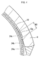
- Double-headed arrow (W2) in FIG. 4 indicates the width where edge part (12a) of belt 12 overlaps outer-edge part (24c) of carcass ply 24.
- Width (W2) is referred to as an overlapping width of edge part (12a) of belt 12 and outer-edge part (24c) of carcass ply 24.
- Overlapping width (W2) is measured along the surface where edge part (12a) is bonded to outer-edge part (24c).
- turn-up portion (24b) of carcass ply 24 overlaps main portion (24a) to reinforce sidewall 6.
- Carcass ply 24 contributes to enhancing the rigidity of the region from core 20 to edge part (12a) of belt 12.
- outer-edge part (24c) is fixed by edge part (12a) and outer-edge part (24c) which overlap each other.
- the rigidity of the region from core 20 to edge part (12a) of belt 12 is significantly improved compared with a tire without such a fixed structure.
- core 20 and carcass ply 24 structured as above, riding comfort and steering stability of tire 2 are both enhanced.
- tire 2 there is no need to provide a reinforcement-rubber layer that extends beyond the radially outer edge of flange 34 in a radially outward direction from core 20.
- Tire 2 exhibits sufficient rigidity without having a reinforcement layer.
- the combination of core 20 and carcass 24 contributes to the light weight of tire 2.
- outer-edge part (24c) is positioned on the radially inner side of edge part (12a) in tire 2. Outer-edge part (24c) is sandwiched between main portion (24a) and edge part (12a). Edge part (12a) is secured even more strongly. Carcass ply 24 and belt 12 are integrated with each other. Accordingly, tire 2 exhibits even higher rigidity.
- overlapping width (W2) between outer-edge part (24c) and edge part (12a) is preferred to be 5 mm or greater. More preferably, overlapping width (W2) is 10 mm or greater, especially preferably 15 mm or greater. On the other hand, if tire 2 has a greater overlapping width (W2), the rigidity of tread 4 increases too much. Overlapping width (W2) is preferred to be 20 mm or less, more preferably 15 mm or less.
- Inclination angles ( ⁇ 1) and ( ⁇ 2) in tire 2 are each preferred to be 89 degrees or smaller.
- Core 20 inclines from the axially inner side to the outer side in a radially outward direction. Because of such inclination, warping in sidewall 6 is less likely to be inhibited, and the riding comfort of tire 2 will not decrease. From those viewpoints, inclination angles ( ⁇ 1) and ( ⁇ 2) are more preferably 85 degrees or smaller, especially preferably 80 degrees or smaller.
- inclination angles ( ⁇ 1) and ( ⁇ 2) bring excellent steering stability to tire 2.
- inclination angles ( ⁇ 1) and ( ⁇ 2) are preferred to be 50 degrees or greater, more preferably 55 degrees or greater, especially preferably 60 degrees or greater.
- the axial width of core 20 decreases from the radially inner side toward the outer side.
- inclination angle ( ⁇ 1) is set smaller than inclination angle ( ⁇ 2).
- the rigidity of core 20 decreases from the radially inner side toward the outer side.
- Core 20 is far less likely to inhibit warping in sidewall 6.
- Core 20 contributes to enhancing both steering stability and riding comfort.
- the cross-sectional shape of core 20 is preferred to be trapezoidal.
- the cross-sectional shape of core 20 here indicates the shape of the region surrounded by straight lines (L1, L2, L3, L4).
- the cross-sectional shape is the shape of a cross section perpendicular relative to a circumferential direction.
- the number of strands on the radially inner side of core 20 may be set greater than the number of strands on the radially outer side, for example.
- the distance between the wires axially adjacent on the radially inner edge of core 20 may be set greater than the distance between the wires axially adjacent on the radially outer edge.
- a tire was prepared to have the structure shown in FIG. 1 .
- Overlapping width (W2), core height (H1) and inclination angles ( ⁇ 1, ⁇ 2) of the tire are specified in Table 1.
- the tire size was "180/55ZR17.”
- Tires were each prepared the same as in Example 1 except that inclination angles ( ⁇ 1, ⁇ 2) were specified as shown in Table 1.
- Tires were each prepared the same as in Example 1 except that overlapping width (W2) and inclination angles ( ⁇ 1, ⁇ 2) were specified as shown in Tables 1 and 2 respectively.
- Tires were each prepared the same as in Example 1 except that height (H1) and inclination angles ( ⁇ 1, ⁇ 2) were specified as shown in Table 2.
- the tire was prepared the same as in Comparative Example 1 except that height (H1) was specified as shown in Table 2.
- Each tire was mounted on a rim with a size of 17M/CxMT5.50, and air was filled in the tire at an inflation pressure of 290 kPa.
- the flange height (Hf) of the rim was 15 mm.
- a load of 1.3 kN was exerted on the tire.
- the results are shown in Tables 1 and 2 as indices.
- the indices are shown as the value obtained in Comparative Example 1 being set as a base value of 3.0. The greater the value is, the better the evaluation result is.
- Each tire was mounted on a rim with a size of 17M/CxMT5.50, and air was filled in the tire at an inflation pressure of 290 kPa.
- the rim is the same as that used for evaluation of riding comfort.
- Each tire was mounted on a commercially available motorcycle with a displacement of 1300 cm 3 (cc).
- a rider ran the motorcycle on a racing circuit and evaluated steering stability.
- the results are shown in Tables 1 and 2 as indices.
- the indices are shown as the value obtained in Comparative Example 1 being set as a base value of 100. The greater the value is, the better the evaluation result is.
- Example 1 Example 2
- Example 3 Example 6 Overlapping width W2 (mm) none 15 15 15 20 Core height H1 (mm) 11 11 11 11 11 Inclination angle ⁇ 1 (°) 90 60 60 85 85 Inclination angle ⁇ 2 (°) 90 60 70 85 85 Riding comfort 100 110 115 105 105 Steering stability 3.0 3.5 5.0 4.0 3.5 Table 2 Evaluation Results
- Example 4 Example 5 Comp.
- Example 2 Comp.
- Example 3 Overlapping width W2 (mm) 5 15 15 none Core height H1 (mm) 11 14 15 15 Inclination angle ⁇ 1 (°) 85 85 85 85 90
- the structures described above are not limited to tires for motorcycles, but can be employed in any pneumatic tire having a carcass, belt and core.
- Carcass ply 24 of tire 2 is provided with main portion (24a) bridging one bead 8 to the other bead 8 and with turn-up portion (24b) positioned on the axially outer side of each bead 8 to extend in a radially outward direction.
- Beads 8 each have core 20 which includes a wire extending in a circumferential direction.
- the number of strands in core 20 is two or greater.
- the number of turns is at least three times the number of strands in core 20.
- the radially outer edge of the wire is positioned on the radially inner side of the radially outer edge of flange 34 of rim 22.
- Outer-edge part (24c) of turn-up portion (24b) overlaps edge part (12a) of belt 12.
Applications Claiming Priority (1)
| Application Number | Priority Date | Filing Date | Title |
|---|---|---|---|
| JP2014103258A JP5946490B2 (ja) | 2014-05-19 | 2014-05-19 | 空気入りタイヤ |
Publications (2)
| Publication Number | Publication Date |
|---|---|
| EP2946946A1 true EP2946946A1 (fr) | 2015-11-25 |
| EP2946946B1 EP2946946B1 (fr) | 2018-07-11 |
Family
ID=53175322
Family Applications (1)
| Application Number | Title | Priority Date | Filing Date |
|---|---|---|---|
| EP15167081.7A Active EP2946946B1 (fr) | 2014-05-19 | 2015-05-11 | Pneumatique |
Country Status (4)
| Country | Link |
|---|---|
| US (1) | US20150328938A1 (fr) |
| EP (1) | EP2946946B1 (fr) |
| JP (1) | JP5946490B2 (fr) |
| CN (1) | CN105082894B (fr) |
Families Citing this family (7)
| Publication number | Priority date | Publication date | Assignee | Title |
|---|---|---|---|---|
| JP6848262B2 (ja) * | 2016-08-22 | 2021-03-24 | 住友ゴム工業株式会社 | 空気入りタイヤ |
| JP6828390B2 (ja) * | 2016-11-16 | 2021-02-10 | 住友ゴム工業株式会社 | 空気入りタイヤ |
| JP6834922B2 (ja) * | 2017-12-01 | 2021-02-24 | 横浜ゴム株式会社 | 空気入りタイヤ |
| JP6988415B2 (ja) * | 2017-12-04 | 2022-01-05 | 横浜ゴム株式会社 | 空気入りタイヤ |
| JP7190308B2 (ja) * | 2018-09-28 | 2022-12-15 | 株式会社ブリヂストン | タイヤ |
| JP7132172B2 (ja) * | 2019-05-07 | 2022-09-06 | 株式会社ブリヂストン | 空気入りタイヤ |
| JP7358856B2 (ja) * | 2019-09-03 | 2023-10-11 | 住友ゴム工業株式会社 | 空気入りタイヤ |
Citations (7)
| Publication number | Priority date | Publication date | Assignee | Title |
|---|---|---|---|---|
| JP2001097010A (ja) | 1999-09-30 | 2001-04-10 | Bridgestone Corp | 空気入りタイヤ |
| JP2002127712A (ja) * | 2000-10-27 | 2002-05-08 | Sumitomo Rubber Ind Ltd | 空気入りタイヤ |
| WO2008061544A1 (fr) * | 2006-11-22 | 2008-05-29 | Pirelli Tyre S.P.A. | Pneu avec tringle légère |
| FR2924979A1 (fr) * | 2007-12-18 | 2009-06-19 | Michelin Soc Tech | Pneumatique radial allege |
| WO2010034593A1 (fr) * | 2008-09-29 | 2010-04-01 | Continental Aktiengesellschaft | Pneu de véhicule |
| JP2010137637A (ja) | 2008-12-10 | 2010-06-24 | Sumitomo Rubber Ind Ltd | 空気入りタイヤ |
| JP2011246019A (ja) * | 2010-05-28 | 2011-12-08 | Sumitomo Rubber Ind Ltd | 空気入りタイヤ |
Family Cites Families (8)
| Publication number | Priority date | Publication date | Assignee | Title |
|---|---|---|---|---|
| US5205883A (en) * | 1988-02-23 | 1993-04-27 | The Yokohama Rubber Co., Ltd. | Pneumatic tire with polygonal bead core |
| JPH035218A (ja) * | 1989-06-01 | 1991-01-11 | Yokohama Rubber Co Ltd:The | 空気入りタイヤ |
| JPH04221209A (ja) * | 1990-12-21 | 1992-08-11 | Bridgestone Corp | 軽量ビードを備えた空気入りタイヤ |
| US6257290B1 (en) * | 1998-06-01 | 2001-07-10 | Sumitomo Rubber Industries, Ltd. | Low-aspect tire |
| JP2003063216A (ja) * | 2001-08-22 | 2003-03-05 | Sumitomo Rubber Ind Ltd | 自動二輪車用ラジアルタイヤ |
| EP1534542B1 (fr) * | 2002-07-23 | 2007-01-10 | Société de Technologie Michelin | Pneumatique avec ancrage non-lineaire de structure de renfort |
| JP5702799B2 (ja) * | 2010-10-19 | 2015-04-15 | 株式会社ブリヂストン | 空気入りタイヤ |
| JP2012162204A (ja) * | 2011-02-08 | 2012-08-30 | Bridgestone Corp | 空気入りタイヤおよび、ビードコアの製造方法 |
-
2014
- 2014-05-19 JP JP2014103258A patent/JP5946490B2/ja active Active
-
2015
- 2015-05-08 CN CN201510232356.2A patent/CN105082894B/zh active Active
- 2015-05-11 EP EP15167081.7A patent/EP2946946B1/fr active Active
- 2015-05-18 US US14/714,736 patent/US20150328938A1/en not_active Abandoned
Patent Citations (7)
| Publication number | Priority date | Publication date | Assignee | Title |
|---|---|---|---|---|
| JP2001097010A (ja) | 1999-09-30 | 2001-04-10 | Bridgestone Corp | 空気入りタイヤ |
| JP2002127712A (ja) * | 2000-10-27 | 2002-05-08 | Sumitomo Rubber Ind Ltd | 空気入りタイヤ |
| WO2008061544A1 (fr) * | 2006-11-22 | 2008-05-29 | Pirelli Tyre S.P.A. | Pneu avec tringle légère |
| FR2924979A1 (fr) * | 2007-12-18 | 2009-06-19 | Michelin Soc Tech | Pneumatique radial allege |
| WO2010034593A1 (fr) * | 2008-09-29 | 2010-04-01 | Continental Aktiengesellschaft | Pneu de véhicule |
| JP2010137637A (ja) | 2008-12-10 | 2010-06-24 | Sumitomo Rubber Ind Ltd | 空気入りタイヤ |
| JP2011246019A (ja) * | 2010-05-28 | 2011-12-08 | Sumitomo Rubber Ind Ltd | 空気入りタイヤ |
Also Published As
| Publication number | Publication date |
|---|---|
| JP5946490B2 (ja) | 2016-07-06 |
| CN105082894A (zh) | 2015-11-25 |
| JP2015217824A (ja) | 2015-12-07 |
| CN105082894B (zh) | 2018-12-18 |
| EP2946946B1 (fr) | 2018-07-11 |
| US20150328938A1 (en) | 2015-11-19 |
Similar Documents
| Publication | Publication Date | Title |
|---|---|---|
| EP2946946B1 (fr) | Pneumatique | |
| EP3059102B1 (fr) | Pneumatique | |
| EP1459910B1 (fr) | Pneu radial | |
| EP2944483B1 (fr) | Pneumatique pour moto | |
| JP5944895B2 (ja) | タイヤ | |
| EP2899042B1 (fr) | Pneu de motocyclette | |
| EP3199377B1 (fr) | Pneu de motocyclette pour terrain accidenté | |
| JP6445870B2 (ja) | 空気入りタイヤ | |
| JP5075688B2 (ja) | 自動二輪車用タイヤ | |
| US9783008B2 (en) | Pneumatic tire | |
| JP4584966B2 (ja) | 自動二輪車用タイヤ対 | |
| EP3357715B1 (fr) | Pneumatique | |
| US11331960B2 (en) | Pneumatic tire | |
| JP2008279796A (ja) | 空気入りタイヤ | |
| JP6967949B2 (ja) | 空気入りタイヤ | |
| EP3366492B1 (fr) | Pneu pour véhicule automobile à deux roues | |
| EP3012122B1 (fr) | Pneumatique | |
| JP2011183857A (ja) | 空気入りタイヤ | |
| JP5893824B2 (ja) | 空気入りラジアルタイヤ | |
| JP6133066B2 (ja) | 空気入りタイヤ | |
| JP7324133B2 (ja) | タイヤ | |
| EP3290231B1 (fr) | Pneu de véhicule à deux roues | |
| JP2010105423A (ja) | 二輪自動車用タイヤ対 | |
| EP3189988B1 (fr) | Pneumatique | |
| EP2540528A1 (fr) | Pneu avec éléments de remplissage |
Legal Events
| Date | Code | Title | Description |
|---|---|---|---|
| PUAI | Public reference made under article 153(3) epc to a published international application that has entered the european phase |
Free format text: ORIGINAL CODE: 0009012 |
|
| AK | Designated contracting states |
Kind code of ref document: A1 Designated state(s): AL AT BE BG CH CY CZ DE DK EE ES FI FR GB GR HR HU IE IS IT LI LT LU LV MC MK MT NL NO PL PT RO RS SE SI SK SM TR |
|
| AX | Request for extension of the european patent |
Extension state: BA ME |
|
| 17P | Request for examination filed |
Effective date: 20160519 |
|
| STAA | Information on the status of an ep patent application or granted ep patent |
Free format text: STATUS: EXAMINATION IS IN PROGRESS |
|
| 17Q | First examination report despatched |
Effective date: 20170208 |
|
| GRAP | Despatch of communication of intention to grant a patent |
Free format text: ORIGINAL CODE: EPIDOSNIGR1 |
|
| STAA | Information on the status of an ep patent application or granted ep patent |
Free format text: STATUS: GRANT OF PATENT IS INTENDED |
|
| INTG | Intention to grant announced |
Effective date: 20180201 |
|
| GRAS | Grant fee paid |
Free format text: ORIGINAL CODE: EPIDOSNIGR3 |
|
| GRAA | (expected) grant |
Free format text: ORIGINAL CODE: 0009210 |
|
| STAA | Information on the status of an ep patent application or granted ep patent |
Free format text: STATUS: THE PATENT HAS BEEN GRANTED |
|
| AK | Designated contracting states |
Kind code of ref document: B1 Designated state(s): AL AT BE BG CH CY CZ DE DK EE ES FI FR GB GR HR HU IE IS IT LI LT LU LV MC MK MT NL NO PL PT RO RS SE SI SK SM TR |
|
| REG | Reference to a national code |
Ref country code: GB Ref legal event code: FG4D |
|
| REG | Reference to a national code |
Ref country code: CH Ref legal event code: EP |
|
| REG | Reference to a national code |
Ref country code: AT Ref legal event code: REF Ref document number: 1016491 Country of ref document: AT Kind code of ref document: T Effective date: 20180715 |
|
| REG | Reference to a national code |
Ref country code: IE Ref legal event code: FG4D |
|
| REG | Reference to a national code |
Ref country code: DE Ref legal event code: R096 Ref document number: 602015013257 Country of ref document: DE |
|
| REG | Reference to a national code |
Ref country code: NL Ref legal event code: MP Effective date: 20180711 |
|
| REG | Reference to a national code |
Ref country code: LT Ref legal event code: MG4D |
|
| REG | Reference to a national code |
Ref country code: AT Ref legal event code: MK05 Ref document number: 1016491 Country of ref document: AT Kind code of ref document: T Effective date: 20180711 |
|
| PG25 | Lapsed in a contracting state [announced via postgrant information from national office to epo] |
Ref country code: NL Free format text: LAPSE BECAUSE OF FAILURE TO SUBMIT A TRANSLATION OF THE DESCRIPTION OR TO PAY THE FEE WITHIN THE PRESCRIBED TIME-LIMIT Effective date: 20180711 |
|
| PG25 | Lapsed in a contracting state [announced via postgrant information from national office to epo] |
Ref country code: FI Free format text: LAPSE BECAUSE OF FAILURE TO SUBMIT A TRANSLATION OF THE DESCRIPTION OR TO PAY THE FEE WITHIN THE PRESCRIBED TIME-LIMIT Effective date: 20180711 Ref country code: RS Free format text: LAPSE BECAUSE OF FAILURE TO SUBMIT A TRANSLATION OF THE DESCRIPTION OR TO PAY THE FEE WITHIN THE PRESCRIBED TIME-LIMIT Effective date: 20180711 Ref country code: AT Free format text: LAPSE BECAUSE OF FAILURE TO SUBMIT A TRANSLATION OF THE DESCRIPTION OR TO PAY THE FEE WITHIN THE PRESCRIBED TIME-LIMIT Effective date: 20180711 Ref country code: IS Free format text: LAPSE BECAUSE OF FAILURE TO SUBMIT A TRANSLATION OF THE DESCRIPTION OR TO PAY THE FEE WITHIN THE PRESCRIBED TIME-LIMIT Effective date: 20181111 Ref country code: NO Free format text: LAPSE BECAUSE OF FAILURE TO SUBMIT A TRANSLATION OF THE DESCRIPTION OR TO PAY THE FEE WITHIN THE PRESCRIBED TIME-LIMIT Effective date: 20181011 Ref country code: SE Free format text: LAPSE BECAUSE OF FAILURE TO SUBMIT A TRANSLATION OF THE DESCRIPTION OR TO PAY THE FEE WITHIN THE PRESCRIBED TIME-LIMIT Effective date: 20180711 Ref country code: GR Free format text: LAPSE BECAUSE OF FAILURE TO SUBMIT A TRANSLATION OF THE DESCRIPTION OR TO PAY THE FEE WITHIN THE PRESCRIBED TIME-LIMIT Effective date: 20181012 Ref country code: BG Free format text: LAPSE BECAUSE OF FAILURE TO SUBMIT A TRANSLATION OF THE DESCRIPTION OR TO PAY THE FEE WITHIN THE PRESCRIBED TIME-LIMIT Effective date: 20181011 Ref country code: LT Free format text: LAPSE BECAUSE OF FAILURE TO SUBMIT A TRANSLATION OF THE DESCRIPTION OR TO PAY THE FEE WITHIN THE PRESCRIBED TIME-LIMIT Effective date: 20180711 Ref country code: PL Free format text: LAPSE BECAUSE OF FAILURE TO SUBMIT A TRANSLATION OF THE DESCRIPTION OR TO PAY THE FEE WITHIN THE PRESCRIBED TIME-LIMIT Effective date: 20180711 |
|
| PG25 | Lapsed in a contracting state [announced via postgrant information from national office to epo] |
Ref country code: AL Free format text: LAPSE BECAUSE OF FAILURE TO SUBMIT A TRANSLATION OF THE DESCRIPTION OR TO PAY THE FEE WITHIN THE PRESCRIBED TIME-LIMIT Effective date: 20180711 Ref country code: LV Free format text: LAPSE BECAUSE OF FAILURE TO SUBMIT A TRANSLATION OF THE DESCRIPTION OR TO PAY THE FEE WITHIN THE PRESCRIBED TIME-LIMIT Effective date: 20180711 Ref country code: HR Free format text: LAPSE BECAUSE OF FAILURE TO SUBMIT A TRANSLATION OF THE DESCRIPTION OR TO PAY THE FEE WITHIN THE PRESCRIBED TIME-LIMIT Effective date: 20180711 Ref country code: ES Free format text: LAPSE BECAUSE OF FAILURE TO SUBMIT A TRANSLATION OF THE DESCRIPTION OR TO PAY THE FEE WITHIN THE PRESCRIBED TIME-LIMIT Effective date: 20180711 |
|
| REG | Reference to a national code |
Ref country code: DE Ref legal event code: R097 Ref document number: 602015013257 Country of ref document: DE |
|
| PG25 | Lapsed in a contracting state [announced via postgrant information from national office to epo] |
Ref country code: CZ Free format text: LAPSE BECAUSE OF FAILURE TO SUBMIT A TRANSLATION OF THE DESCRIPTION OR TO PAY THE FEE WITHIN THE PRESCRIBED TIME-LIMIT Effective date: 20180711 Ref country code: IT Free format text: LAPSE BECAUSE OF FAILURE TO SUBMIT A TRANSLATION OF THE DESCRIPTION OR TO PAY THE FEE WITHIN THE PRESCRIBED TIME-LIMIT Effective date: 20180711 Ref country code: RO Free format text: LAPSE BECAUSE OF FAILURE TO SUBMIT A TRANSLATION OF THE DESCRIPTION OR TO PAY THE FEE WITHIN THE PRESCRIBED TIME-LIMIT Effective date: 20180711 Ref country code: EE Free format text: LAPSE BECAUSE OF FAILURE TO SUBMIT A TRANSLATION OF THE DESCRIPTION OR TO PAY THE FEE WITHIN THE PRESCRIBED TIME-LIMIT Effective date: 20180711 |
|
| PLBE | No opposition filed within time limit |
Free format text: ORIGINAL CODE: 0009261 |
|
| STAA | Information on the status of an ep patent application or granted ep patent |
Free format text: STATUS: NO OPPOSITION FILED WITHIN TIME LIMIT |
|
| PG25 | Lapsed in a contracting state [announced via postgrant information from national office to epo] |
Ref country code: DK Free format text: LAPSE BECAUSE OF FAILURE TO SUBMIT A TRANSLATION OF THE DESCRIPTION OR TO PAY THE FEE WITHIN THE PRESCRIBED TIME-LIMIT Effective date: 20180711 Ref country code: SM Free format text: LAPSE BECAUSE OF FAILURE TO SUBMIT A TRANSLATION OF THE DESCRIPTION OR TO PAY THE FEE WITHIN THE PRESCRIBED TIME-LIMIT Effective date: 20180711 Ref country code: SK Free format text: LAPSE BECAUSE OF FAILURE TO SUBMIT A TRANSLATION OF THE DESCRIPTION OR TO PAY THE FEE WITHIN THE PRESCRIBED TIME-LIMIT Effective date: 20180711 |
|
| 26N | No opposition filed |
Effective date: 20190412 |
|
| PG25 | Lapsed in a contracting state [announced via postgrant information from national office to epo] |
Ref country code: SI Free format text: LAPSE BECAUSE OF FAILURE TO SUBMIT A TRANSLATION OF THE DESCRIPTION OR TO PAY THE FEE WITHIN THE PRESCRIBED TIME-LIMIT Effective date: 20180711 |
|
| REG | Reference to a national code |
Ref country code: CH Ref legal event code: PL |
|
| GBPC | Gb: european patent ceased through non-payment of renewal fee |
Effective date: 20190511 |
|
| PG25 | Lapsed in a contracting state [announced via postgrant information from national office to epo] |
Ref country code: LI Free format text: LAPSE BECAUSE OF NON-PAYMENT OF DUE FEES Effective date: 20190531 Ref country code: MC Free format text: LAPSE BECAUSE OF FAILURE TO SUBMIT A TRANSLATION OF THE DESCRIPTION OR TO PAY THE FEE WITHIN THE PRESCRIBED TIME-LIMIT Effective date: 20180711 Ref country code: CH Free format text: LAPSE BECAUSE OF NON-PAYMENT OF DUE FEES Effective date: 20190531 |
|
| REG | Reference to a national code |
Ref country code: BE Ref legal event code: MM Effective date: 20190531 |
|
| PG25 | Lapsed in a contracting state [announced via postgrant information from national office to epo] |
Ref country code: LU Free format text: LAPSE BECAUSE OF NON-PAYMENT OF DUE FEES Effective date: 20190511 |
|
| PG25 | Lapsed in a contracting state [announced via postgrant information from national office to epo] |
Ref country code: TR Free format text: LAPSE BECAUSE OF FAILURE TO SUBMIT A TRANSLATION OF THE DESCRIPTION OR TO PAY THE FEE WITHIN THE PRESCRIBED TIME-LIMIT Effective date: 20180711 |
|
| PG25 | Lapsed in a contracting state [announced via postgrant information from national office to epo] |
Ref country code: IE Free format text: LAPSE BECAUSE OF NON-PAYMENT OF DUE FEES Effective date: 20190511 Ref country code: GB Free format text: LAPSE BECAUSE OF NON-PAYMENT OF DUE FEES Effective date: 20190511 |
|
| PG25 | Lapsed in a contracting state [announced via postgrant information from national office to epo] |
Ref country code: BE Free format text: LAPSE BECAUSE OF NON-PAYMENT OF DUE FEES Effective date: 20190531 |
|
| PG25 | Lapsed in a contracting state [announced via postgrant information from national office to epo] |
Ref country code: PT Free format text: LAPSE BECAUSE OF FAILURE TO SUBMIT A TRANSLATION OF THE DESCRIPTION OR TO PAY THE FEE WITHIN THE PRESCRIBED TIME-LIMIT Effective date: 20181111 |
|
| PG25 | Lapsed in a contracting state [announced via postgrant information from national office to epo] |
Ref country code: CY Free format text: LAPSE BECAUSE OF FAILURE TO SUBMIT A TRANSLATION OF THE DESCRIPTION OR TO PAY THE FEE WITHIN THE PRESCRIBED TIME-LIMIT Effective date: 20180711 |
|
| PG25 | Lapsed in a contracting state [announced via postgrant information from national office to epo] |
Ref country code: MT Free format text: LAPSE BECAUSE OF FAILURE TO SUBMIT A TRANSLATION OF THE DESCRIPTION OR TO PAY THE FEE WITHIN THE PRESCRIBED TIME-LIMIT Effective date: 20180711 Ref country code: HU Free format text: LAPSE BECAUSE OF FAILURE TO SUBMIT A TRANSLATION OF THE DESCRIPTION OR TO PAY THE FEE WITHIN THE PRESCRIBED TIME-LIMIT; INVALID AB INITIO Effective date: 20150511 |
|
| PG25 | Lapsed in a contracting state [announced via postgrant information from national office to epo] |
Ref country code: MK Free format text: LAPSE BECAUSE OF FAILURE TO SUBMIT A TRANSLATION OF THE DESCRIPTION OR TO PAY THE FEE WITHIN THE PRESCRIBED TIME-LIMIT Effective date: 20180711 |
|
| REG | Reference to a national code |
Ref country code: FR Ref legal event code: PLFP Year of fee payment: 9 |
|
| PGFP | Annual fee paid to national office [announced via postgrant information from national office to epo] |
Ref country code: FR Payment date: 20230411 Year of fee payment: 9 Ref country code: DE Payment date: 20230331 Year of fee payment: 9 |