EP2944587B1 - Gesloten transportband - Google Patents
Gesloten transportband Download PDFInfo
- Publication number
- EP2944587B1 EP2944587B1 EP15001417.3A EP15001417A EP2944587B1 EP 2944587 B1 EP2944587 B1 EP 2944587B1 EP 15001417 A EP15001417 A EP 15001417A EP 2944587 B1 EP2944587 B1 EP 2944587B1
- Authority
- EP
- European Patent Office
- Prior art keywords
- conveyor belt
- housing
- closed
- belt according
- drum
- Prior art date
- Legal status (The legal status is an assumption and is not a legal conclusion. Google has not performed a legal analysis and makes no representation as to the accuracy of the status listed.)
- Active
Links
Images

Classifications
-
- B—PERFORMING OPERATIONS; TRANSPORTING
- B65—CONVEYING; PACKING; STORING; HANDLING THIN OR FILAMENTARY MATERIAL
- B65G—TRANSPORT OR STORAGE DEVICES, e.g. CONVEYORS FOR LOADING OR TIPPING, SHOP CONVEYOR SYSTEMS OR PNEUMATIC TUBE CONVEYORS
- B65G21/00—Supporting or protective framework or housings for endless load-carriers or traction elements of belt or chain conveyors
- B65G21/20—Means incorporated in, or attached to, framework or housings for guiding load-carriers, traction elements or loads supported on moving surfaces
-
- B—PERFORMING OPERATIONS; TRANSPORTING
- B65—CONVEYING; PACKING; STORING; HANDLING THIN OR FILAMENTARY MATERIAL
- B65G—TRANSPORT OR STORAGE DEVICES, e.g. CONVEYORS FOR LOADING OR TIPPING, SHOP CONVEYOR SYSTEMS OR PNEUMATIC TUBE CONVEYORS
- B65G15/00—Conveyors having endless load-conveying surfaces, i.e. belts and like continuous members, to which tractive effort is transmitted by means other than endless driving elements of similar configuration
- B65G15/28—Conveyors with a load-conveying surface formed by a single flat belt, not otherwise provided for
-
- B—PERFORMING OPERATIONS; TRANSPORTING
- B65—CONVEYING; PACKING; STORING; HANDLING THIN OR FILAMENTARY MATERIAL
- B65G—TRANSPORT OR STORAGE DEVICES, e.g. CONVEYORS FOR LOADING OR TIPPING, SHOP CONVEYOR SYSTEMS OR PNEUMATIC TUBE CONVEYORS
- B65G15/00—Conveyors having endless load-conveying surfaces, i.e. belts and like continuous members, to which tractive effort is transmitted by means other than endless driving elements of similar configuration
- B65G15/60—Arrangements for supporting or guiding belts, e.g. by fluid jets
- B65G15/62—Guides for sliding belts
-
- B—PERFORMING OPERATIONS; TRANSPORTING
- B65—CONVEYING; PACKING; STORING; HANDLING THIN OR FILAMENTARY MATERIAL
- B65G—TRANSPORT OR STORAGE DEVICES, e.g. CONVEYORS FOR LOADING OR TIPPING, SHOP CONVEYOR SYSTEMS OR PNEUMATIC TUBE CONVEYORS
- B65G21/00—Supporting or protective framework or housings for endless load-carriers or traction elements of belt or chain conveyors
- B65G21/08—Protective roofs or arch supports therefor
-
- B—PERFORMING OPERATIONS; TRANSPORTING
- B65—CONVEYING; PACKING; STORING; HANDLING THIN OR FILAMENTARY MATERIAL
- B65G—TRANSPORT OR STORAGE DEVICES, e.g. CONVEYORS FOR LOADING OR TIPPING, SHOP CONVEYOR SYSTEMS OR PNEUMATIC TUBE CONVEYORS
- B65G23/00—Driving gear for endless conveyors; Belt- or chain-tensioning arrangements
- B65G23/02—Belt- or chain-engaging elements
- B65G23/04—Drums, rollers, or wheels
-
- B—PERFORMING OPERATIONS; TRANSPORTING
- B65—CONVEYING; PACKING; STORING; HANDLING THIN OR FILAMENTARY MATERIAL
- B65G—TRANSPORT OR STORAGE DEVICES, e.g. CONVEYORS FOR LOADING OR TIPPING, SHOP CONVEYOR SYSTEMS OR PNEUMATIC TUBE CONVEYORS
- B65G37/00—Combinations of mechanical conveyors of the same kind, or of different kinds, of interest apart from their application in particular machines or use in particular manufacturing processes
-
- B—PERFORMING OPERATIONS; TRANSPORTING
- B65—CONVEYING; PACKING; STORING; HANDLING THIN OR FILAMENTARY MATERIAL
- B65G—TRANSPORT OR STORAGE DEVICES, e.g. CONVEYORS FOR LOADING OR TIPPING, SHOP CONVEYOR SYSTEMS OR PNEUMATIC TUBE CONVEYORS
- B65G39/00—Rollers, e.g. drive rollers, or arrangements thereof incorporated in roller-ways or other types of mechanical conveyors
- B65G39/10—Arrangements of rollers
- B65G39/12—Arrangements of rollers mounted on framework
-
- B—PERFORMING OPERATIONS; TRANSPORTING
- B65—CONVEYING; PACKING; STORING; HANDLING THIN OR FILAMENTARY MATERIAL
- B65G—TRANSPORT OR STORAGE DEVICES, e.g. CONVEYORS FOR LOADING OR TIPPING, SHOP CONVEYOR SYSTEMS OR PNEUMATIC TUBE CONVEYORS
- B65G69/00—Auxiliary measures taken, or devices used, in connection with loading or unloading
- B65G69/18—Preventing escape of dust
- B65G69/181—Preventing escape of dust by means of sealed systems
Definitions
- the present invention relates to a closed conveyor belt. More specifically, the invention concerns a closed conveyor belt with a housing that encloses a conveyor belt that is set in motion by means of a drive.
- This drive is often in the form of a drive drum or drive roller in combination with a return drum or return roller.
- the conveyor belt is a long closed loop as it were that is affixed around the two aforementioned drums so that two tracks are formed in this way: a top track on which the product to be transported is laid and a bottom track that is the returning conveyor belt.
- the conveyor belt moves in the housing by being driven by the drive drum.
- the space between the two tracks in which both drums are located will be designated hereinafter as 'the interspace'.
- Such conveyor belts are used for transporting fragile or dusty products or materials, whereby the housing will ensure that the environment around the conveyor belt is not fouled, for example by products falling from the conveyor belt onto the ground or by dust originating from the products getting into the environment. This will also contribute to better hygiene.
- US 2012018283 A1 discloses a closed conveyor belt according to the preamble of claim 1.
- US4674626 describes an alleged leakproof endless belt conveyor.
- the side edges and return end of the endless belt conveyor are sealed to prevent particulate material deposited thereon from leaking off the sides and being lost.
- Such conveyor belts can also be used for hazardous products for example, as possible interaction or contact between the product and the external environment is excluded.
- the edge of the conveyor belt will be at a certain distance from the housing. This means that there is a certain space or clearance between the edge of the conveyor belt and the housing.
- a closed conveyor belt which comprises a housing that encloses a conveyor belt that can be set in motion by means of a drive, whereby both edges of the conveyor belt, that extend in the direction of movement of the conveyor belt, extend through the housing by a protruding section that extends through slots provided to this end in the housing.
- the drive can be constructed in the form of a drive drum and a return drum.
- a drive drum and return drum also means a drive roller and return roller.
- Another advantage is that no material can get into the interspace between the two tracks of the conveyor belt.
- the aforementioned drums that are in this interspace are completely screened off from the material or product that is moved with the conveyor belt so that the drums cannot be blocked or damaged.
- the drive is formed by a return drum and drive drum, and the ends of the return drum and/or drive drum extend through the housing through openings provided to this end in the housing.
- the aforementioned protruding section of the conveyor belt and/or the protruding section of the return drum and/or drive drum are covered by a guard.
- means are provided that ensure a barrier between the protruding section and the slot in the housing and/or between the drive drum and the opening concerned in the housing and/or between the return drum and the opening concerned in the housing.
- the housing will as it were be completely closed off from the external environment.
- the interspace between the two tracks of the conveyor belt is as good as hermetically sealed in this way.
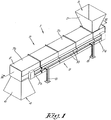
- the closed conveyor belt 1 according to the invention shown in figures 1 and 2 comprises a housing 2, which in this case is provided with an input opening 3 and an output opening 4 for the input and output respectively of the material or products to be transported.
- the input opening 3 and output opening 4 are provided with an inlet hopper 5 and outlet hopper 6 respectively. It is clear that only one or none of the two aforementioned hoppers 5, 6 can be present.
- the closed conveyor belt 1 can be used for ground or shredded plastic material for example that is produced during waste processing.
- the housing 2 is constructed from different parts, a number of which are indicated by reference figures 7a to 7d .
- the parts 7a-7d are assembled to form the housing 2.
- the housing 2 is also provided with supporting legs 8 with which the closed conveyor belt 1 can be placed on a base.
- the housing is provided with guards 10 on two opposite sides 9.
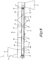
- Figure 3 shows a cross-section according to line III-III of figure 2 .
- the drive drum 12 will ensure that the conveyor belt 11 is set in motion in the direction of movement according to arrow P.
- the top track 14 moves in the direction from the input opening 3 to the output opening 4.
- the conveyor belt 11 will demarcate three zones or compartments in the housing 2: a top compartment 16 that is above the conveyor belt 11, a bottom compartment 17 that is below the conveyor belt 11, and an interspace 18 that is enclosed by the two tracks 14 and 15 of the conveyor belt 11.
- the conveyor belt 11 is provided with catches 19 that extend transversely to the direction of movement P of the conveyor belt 11.
- the catches 19 are constructed as transverse slats on the conveyor belt 11.
- the conveyor belt 11 is at least partially supported by a flat plate 20 or similar.
- top track 14 of the conveyor belt 11 is supported by means of a flat plate 20 that extends from the drive drum 12 to the return drum 13. It is possible that a flat plate 20 is also provided that is just above and against the bottom track 15.
- the flat plate 20 will ensure that the conveyor belt 11 will not sag under the weight of the material or products that are on it.
- the aforementioned flat plate 20 is supported by means of reinforcing ribs 21 or supporting slats that are provided in the interspace 18 enclosed by the conveyor belt 11, whereby the reinforcing ribs 21 or supporting slats are placed in crossed pairs. As can be seen in figure 3 , they are positioned spread over the entire length of the conveyor belt 11.
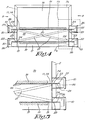
- Figure 4 shows a cross-section according to line IV-IV of figure 2 . This drawing clearly shows that the edges 22 of the conveyor belt, that extend in the direction of movement P of the conveyor belt 11, extend by a protruding section 23 through the housing 2.
- the housing 2 is provided with slots 24 to this end, through which the protruding section 23 comes out of the housing 2.
- the flat plate 20 also protrudes through the aforementioned slots 24 by its two opposite edges 25.
- the slots 24 have the shape of a type of long loop in the two opposite sides 9.
- the slot 24 is formed by cutaways being formed between the composite parts 7a-7d of the housing 2, after they have been assembled to form the housing 2, in order to form the slot 24.
- the slots 24 are formed automatically. This has the advantage that after assembling the housing 2 no slots 24 have to be made by drilling, sawing or other processes.
- guards 10 go over the protruding sections 23, 24 of the conveyor belt 11 and the flat plate 20.
- a separate guard 10 is provided for the protruding section 23 of the top track 14 and the bottom track 15. It is of course not excluded that one guard 10 is provided on each side 9 of the housing 2 that comprises both protruding sections 23, 24.
- These means 26 preferably comprise at least one seal, labyrinth seal or brush.
- the means 26 are formed by seals.
- the seals will ensure that dust and material or products of small dimensions cannot get outside through the slot 24.
- FIG. 4 clearly shows the form of the catches 19. In this case they are constructed as slats, but is it is clear that the invention is not limited to this.
- the reinforcing ribs 21 or supporting slats that are placed in crossed pairs can be clearly seen in figure 4 .
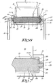
- Figure 6 shows a cross-section according to line VI-VI of figure 2 , whereby figure 7 shows a detail of figure 6 .
- the housing 2 is provided with openings 28. These openings 28 can be formed in a similar way to the slots 24 by the composite parts 7a-7d of the housing 2.
- the shafts 29 of the drums 12, 13 are affixed in the housing 2 on supports 30 provided to this end.
- means 26 are also provided that ensure a barrier between the drums 12, 13 and the openings 28 concerned in the housing 2.
- the ends 27 of the drum 12, 13 are closed off by guards 10, whereby in this case the guard 10 of the conveyor belt 11 and the guard 10 of the drums 12, 13 form a single unit on both sides of the housing 2.
- the drive means for driving the drive drum 12, such as an electric motor or similar for example, can be outside the housing 2, in the guard 10 or in the drive drum 12 itself, or otherwise.
- the operation of the closed conveyor belt 1 is very simple and as follows.
- the material to be transported such as shredded or ground plastic waste for example, can be introduced in the housing 2 on the conveyor belt 11 via the input opening 3.
- the inlet hopper 5 will provide the guide for the plastic shreds, so that all the material comes onto the top track 14 of the conveyor belt 11.
- the drive drum 12 will set the conveyor belt in motion in the direction of the arrow P, such that the material on the top track 14 will move towards the output opening 4.
- the catches 19 will hereby carry the material along as it were, which can be important when the conveyor belt 11 is placed at a shallow ascending angle, for example.
- the catches 19 will ensure that the material is held back as it were so that not everything slides to the output opening 4 at the same time, but is gradually brought to the output opening 4.
- the flat plate 20 When relatively heavy products or materials are transported with the conveyor belt 11, the flat plate 20 will ensure that the top track 14 remains nicely flat and will not sag under the influence of the weight of the products or materials. This will guarantee the good operation of the conveyor belt 11.
- the protruding parts 23 and 27 respectively of the conveyor belt 11 and drums 12, 13 will be covered by the guards 10 so that no moving parts are free during the operation of the closed conveyor belt 1. This will increase safety and can prevent damage to these moving parts.
- the outlet hopper 6 will ensure that when leaving the housing 2, the material is guided in the right direction. It is clear that the shape of the inlet hopper 5 and the outlet hopper 6 is not limited to the shapes shown in the drawings. After reversing the conveyor belt 11, the bottom track 15 will move forwards to the return drum 13 in the opposite direction to the top track 14. There the conveyor belt 11 will reverse again as it were and the process can be repeated.
- the present invention is by no means limited to the embodiments described as an example and shown in the drawings, but a closed conveyor belt according to the invention can be realised in all kinds of forms and dimensions without departing from the scope of the claims.
Landscapes
- Engineering & Computer Science (AREA)
- Mechanical Engineering (AREA)
- Belt Conveyors (AREA)
- Processing And Handling Of Plastics And Other Materials For Molding In General (AREA)
- Structure Of Belt Conveyors (AREA)
Claims (14)
- Geschlossenes Transportband mit einem Gehäuse (2), das ein Transportband (11) einschließt, das mit Hilfe eines Antriebs in Bewegung setzbar ist, wobei beide Ränder (22) des Transportbands (11), die sich in der Richtung der Bewegung (P) des Transportbandes erstrecken, sich durch das Gehäuse (2) über einen vorstehenden Abschnitt (23) erstrecken, wobei das Gehäuse mit Schutzvorrichtungen (10) an zwei gegenüberliegenden Seiten (9) versehen ist, dadurch gekennzeichnet, dass das Gehäuse (2) mit Schlitzen (4) versehen ist, durch die der vorstehende Abschnitt (23) des Bandes (11) verläuft und durch die er aus dem Gehäuse (2) gelangt, wobei die Schutzvorrichtungen (10) den vorstehenden Abschnitt (23) des Transportbandes abdecken.
- Geschlossenes Transportband nach Anspruch 1, dadurch gekennzeichnet, dass der Antrieb gebildet ist durch eine Rücklauftrommel (13) und Antriebstrommel (12), wobei die Enden (27) der Rücklauftrommel (13) und/oder der Antriebstrommel (12) durch das Gehäuse (2) durch Öffnungen (28) verlaufen, die dafür in dem Gehäuse (2) vorgesehen sind.
- Geschlossenes Transportband nach Anspruch 1 oder 2, dadurch gekennzeichnet, dass Mittel (26) vorgesehen sind, die eine Barriere zwischen dem vorstehenden Abschnitt (23) und dem Schlitz (24) in dem Gehäuse (2) und/oder zwischen der Antriebstrommel (12) und der Öffnung in dem Gehäuse (2) und/oder zwischen der Rücklauftrommel (13) und der Öffnung (28) in dem Gehäuse (2) sicherstellen.
- Geschlossenes Transportband nach Anspruch 3, dadurch gekennzeichnet, dass die zuvor erwähnten Mittel (26) wenigstens eine Dichtung, Labyrinth-Dichtung oder Bürste umfassen.
- Geschlossenes Transportband nach einem der vorstehenden Ansprüche, dadurch gekennzeichnet, dass der Schlitz (24) und/oder die Öffnung (28) realisiert werden, indem das Gehäuse (2) zusammengebaut ist aus unterschiedlichen Teilen (7a-7d), wobei Ausschnitte ausgebildet werden, um den Schlitz (24) zu bilden und/oder die Öffnung (28) zwischen den unterschiedlichen Teilen (7a-7d), nachdem sie zum Zwecke des Ausbildens des Gehäuses (2) zusammengebaut wurden.
- Geschlossenes Transportband nach einem der vorstehenden Ansprüche 2 bis 5, dadurch gekennzeichnet, dass
das Ende (27) der Rücklauftrommel (13) und/oder Antriebstrommel (12) durch eine Schutzvorrichtung (10) abgesperrt ist. - Geschlossenes Transportband nach Anspruch 5 und 6, dadurch gekennzeichnet, dass die zuvor erwähnten Schutzvorrichtungen (10) eine Einheit bilden.
- Geschlossenes Transportband nach einem der vorstehenden Ansprüche, dadurch gekennzeichnet, dass das Transportband (11) mit Anschlägen (19) versehen ist, die quer zur Richtung der Bewegung (P) des Transportbands (11) verlaufen.
- Geschlossenes Transportbandnach einem der vorstehenden Ansprüche, dadurch gekennzeichnet, dass das Gehäuse (2) mit einer Eingabe-Öffnung (3) und einer Ausgabe-Öffnung (4) versehen ist zum Eingeben bzw. Ausgeben des Materials oder der Produkte, die zu Transportieren sind.
- Geschlossenes Transportband nach Anspruch 9,
dadurch gekennzeichnet, dass die Eingabe-Öffnung (3) und/oder die Ausgabe-Öffnung (4) mit einem Eingabe-Trichter (5) bzw. einem Ausgabe-Trichter (6) versehen sind. - Geschlossenes Transportband nach einem der vorstehen Ansprüche, dadurch gekennzeichnet, dass die Antriebsmittel zum Antreiben der Antriebstrommel (12) sich außerhalb des Gehäuses (2) oder in der Antriebstrommel (12) selbst befinden.
- Geschlossenes Transportband nach einem der vorstehenden Ansprüche, dadurch gekennzeichnet, dass das Transportband (11) zumindest teilweise von einer flachen Platte (20) oder Ähnlichem getragen ist.
- Geschlossenes Transportband nach Anspruch 12, dadurch gekennzeichnet, dass die zuvor erwähnte flache Platte (20) sich durch die zuvor erwähnten Schlitze (24) über zwei gegenüberliegende Ränder (25) erstreckt.
- Geschlossenes Transportband nach einem der vorstehenden Ansprüche 12 oder 13, dadurch gekennzeichnet, dass
die zuvor erwähnte flache Platte (20) mit Hilfe von Verstärkungsrippen (21) oder Stützlamellen getragen wird, die in dem von dem Transportband (11) eingeschlossenen Zwischenraum (18) vorgesehen sind, wobei die Verstärkungsrippen (21) oder Stützlamellen in gekreuzten Paaren angeordnet sind.
Priority Applications (2)
| Application Number | Priority Date | Filing Date | Title |
|---|---|---|---|
| EP17155179.9A EP3184472A1 (de) | 2014-05-15 | 2015-05-12 | Geschlossenes förderband |
| PL15001417T PL2944587T3 (pl) | 2014-05-15 | 2015-05-12 | Zamknięta taśma przenośnika |
Applications Claiming Priority (1)
| Application Number | Priority Date | Filing Date | Title |
|---|---|---|---|
| BE2014/0361A BE1021981B1 (nl) | 2014-05-15 | 2014-05-15 | Gesloten transportband |
Related Child Applications (3)
| Application Number | Title | Priority Date | Filing Date |
|---|---|---|---|
| EP17155179.9A Division EP3184472A1 (de) | 2014-05-15 | 2015-05-12 | Geschlossenes förderband |
| EP17155179.9A Previously-Filed-Application EP3184472A1 (de) | 2014-05-15 | 2015-05-12 | Geschlossenes förderband |
| EP17155179.9A Division-Into EP3184472A1 (de) | 2014-05-15 | 2015-05-12 | Geschlossenes förderband |
Publications (2)
| Publication Number | Publication Date |
|---|---|
| EP2944587A1 EP2944587A1 (de) | 2015-11-18 |
| EP2944587B1 true EP2944587B1 (de) | 2018-07-11 |
Family
ID=51302577
Family Applications (2)
| Application Number | Title | Priority Date | Filing Date |
|---|---|---|---|
| EP15001417.3A Active EP2944587B1 (de) | 2014-05-15 | 2015-05-12 | Gesloten transportband |
| EP17155179.9A Pending EP3184472A1 (de) | 2014-05-15 | 2015-05-12 | Geschlossenes förderband |
Family Applications After (1)
| Application Number | Title | Priority Date | Filing Date |
|---|---|---|---|
| EP17155179.9A Pending EP3184472A1 (de) | 2014-05-15 | 2015-05-12 | Geschlossenes förderband |
Country Status (5)
| Country | Link |
|---|---|
| US (1) | US9440794B2 (de) |
| EP (2) | EP2944587B1 (de) |
| BE (1) | BE1021981B1 (de) |
| ES (1) | ES2686098T3 (de) |
| PL (1) | PL2944587T3 (de) |
Families Citing this family (11)
| Publication number | Priority date | Publication date | Assignee | Title |
|---|---|---|---|---|
| AU2015215884B2 (en) * | 2014-10-28 | 2018-08-23 | Haze Ag Pty Ltd | Modular broadcast spreader |
| BE1025035B1 (nl) | 2017-03-06 | 2018-10-10 | Clean Conveyor Belt BVBA | Transportbandsysteem |
| CN106938774A (zh) * | 2017-04-21 | 2017-07-11 | 上海怡黄木业有限公司 | 用于饰面板热压成型工艺中的送料除尘系统 |
| CN107857059A (zh) * | 2017-12-07 | 2018-03-30 | 天津日振自动化设备有限公司 | 一种传送平稳的箱体式传送设备 |
| CN110406999A (zh) * | 2019-06-27 | 2019-11-05 | 张家港市华申工业橡塑制品有限公司 | 一种风式集尘装置 |
| BE1027494B1 (nl) | 2019-08-12 | 2021-03-16 | Clean Conveyor Belt BVBA | Transportband met opstaande ribben |
| CN112265842A (zh) * | 2020-09-24 | 2021-01-26 | 安徽华宇机械制造有限公司 | 一种具备除尘除杂功能的一体式封闭型粮食输送机 |
| CN112676292B (zh) * | 2020-12-29 | 2022-05-20 | 浙江林龙物流有限公司 | 一种机制砂的粉尘分离装置 |
| CN112744618A (zh) * | 2021-01-15 | 2021-05-04 | 国能信控互联技术有限公司 | 一种火电厂输煤皮带降尘防漏智能化系统及方法 |
| CN113163083B (zh) * | 2021-03-30 | 2022-08-30 | 盛泰光电科技股份有限公司 | 用于摄像头模组的生产方法 |
| CN114348552A (zh) * | 2022-01-05 | 2022-04-15 | 中国建材国际工程集团有限公司 | 一种新型密闭带式输送机 |
Citations (2)
| Publication number | Priority date | Publication date | Assignee | Title |
|---|---|---|---|---|
| US4674626A (en) * | 1983-12-15 | 1987-06-23 | M. L. Eakes Co. | Leakproof endless belt conveyor |
| US5762712A (en) * | 1995-08-22 | 1998-06-09 | Winkler & Dunnebier Maschinenfabrik Und Eisengiesserei Kg | Sprinkling device for metered application of super absorbing swelling substances |
Family Cites Families (14)
| Publication number | Priority date | Publication date | Assignee | Title |
|---|---|---|---|---|
| DE1041416B (de) * | 1954-11-25 | 1958-10-16 | Eickhoff Geb | Fuehrungsgestell fuer Plattenbandfoerderer |
| GB1566549A (en) * | 1976-10-25 | 1980-05-08 | Slowley S G | Conveyors |
| US4204595A (en) * | 1978-11-16 | 1980-05-27 | Amax Inc. | Adjustable conveyor belt skirtboard |
| US4321996A (en) * | 1979-05-10 | 1982-03-30 | A. O. Smith Harvestore Products, Inc. | Cleated belt forage conveyor |
| US4674627A (en) * | 1984-11-08 | 1987-06-23 | Proctor & Schwartz, Inc. | Sanitary conveyor assembly |
| US5129508A (en) * | 1991-03-25 | 1992-07-14 | Keith Shelstad | Dust control system |
| US5400897A (en) * | 1994-03-16 | 1995-03-28 | Doyle Equipment Manufacturing Company | Fertilizer conveyor |
| US5660283A (en) * | 1995-03-13 | 1997-08-26 | Groh; George John | High cleat conveyor system |
| US20020139643A1 (en) * | 2000-02-07 | 2002-10-03 | Jeff Peltier | Conveyor system |
| EP1148002B1 (de) * | 2000-04-18 | 2005-10-12 | Machinefabriek Bollegraaf Appingedam B.V. | Förderer zum Fördern von Schüttgut |
| JP2004051338A (ja) * | 2002-07-23 | 2004-02-19 | Bando Chem Ind Ltd | 粉体搬送装置 |
| US7673741B2 (en) * | 2005-08-08 | 2010-03-09 | Inter-Source Recovery Systems | Apparatus and method for conveying materials |
| US20120018283A1 (en) * | 2010-07-22 | 2012-01-26 | Timothy Dallner | Easy clean conveyor for food products |
| US8925718B2 (en) * | 2013-03-07 | 2015-01-06 | Engineeringology Inc. | Modular support system |
-
2014
- 2014-05-15 BE BE2014/0361A patent/BE1021981B1/nl active IP Right Grant
-
2015
- 2015-05-12 EP EP15001417.3A patent/EP2944587B1/de active Active
- 2015-05-12 ES ES15001417.3T patent/ES2686098T3/es active Active
- 2015-05-12 EP EP17155179.9A patent/EP3184472A1/de active Pending
- 2015-05-12 PL PL15001417T patent/PL2944587T3/pl unknown
- 2015-05-14 US US14/712,164 patent/US9440794B2/en active Active
Patent Citations (2)
| Publication number | Priority date | Publication date | Assignee | Title |
|---|---|---|---|---|
| US4674626A (en) * | 1983-12-15 | 1987-06-23 | M. L. Eakes Co. | Leakproof endless belt conveyor |
| US5762712A (en) * | 1995-08-22 | 1998-06-09 | Winkler & Dunnebier Maschinenfabrik Und Eisengiesserei Kg | Sprinkling device for metered application of super absorbing swelling substances |
Also Published As
| Publication number | Publication date |
|---|---|
| EP3184472A1 (de) | 2017-06-28 |
| EP2944587A1 (de) | 2015-11-18 |
| US9440794B2 (en) | 2016-09-13 |
| ES2686098T3 (es) | 2018-10-16 |
| US20150329293A1 (en) | 2015-11-19 |
| PL2944587T3 (pl) | 2019-01-31 |
| BE1021981B1 (nl) | 2016-02-01 |
Similar Documents
| Publication | Publication Date | Title |
|---|---|---|
| EP2944587B1 (de) | Gesloten transportband | |
| KR101658829B1 (ko) | 스크류 컨베이어 스케일 제거 장치 | |
| US2554589A (en) | Chain link | |
| CN105980271B (zh) | 输送链支撑件 | |
| KR102203709B1 (ko) | 벨트 컨베이어 | |
| CN104640788A (zh) | 带有受料斗部段保护的传送带的斗式传送带运输机 | |
| CN204711677U (zh) | 机床的碎屑传送装置 | |
| KR101295598B1 (ko) | 벨트컨베이어용 동결광 파쇄장치 | |
| KR20190000672A (ko) | 회전형 슈트 라이너 및 이를 포함하는 슈트 | |
| JP5959455B2 (ja) | フローコンベヤ | |
| KR20130120943A (ko) | 벨트컨베이어용 낙광 제거장치 | |
| US6505727B2 (en) | Slide gate for a conveyor system | |
| KR101187763B1 (ko) | 벨트 컨베이어용 클리너 | |
| KR101062952B1 (ko) | 벨트 컨베이어의 낙하물 처리장치 | |
| US443488A (en) | Half to john b | |
| KR101295597B1 (ko) | 벨트컨베이어용 낙광 제거장치 | |
| US614847A (en) | Endless conveyer | |
| JP2016132533A (ja) | 搬送装置 | |
| KR20130059885A (ko) | 원료내 이물질 제거장치 | |
| CN106572647B (zh) | 用于输送沙的系统和方法 | |
| KR20190001589U (ko) | 컨베이어용 부착물 제거장치 | |
| KR102127216B1 (ko) | 식품용 탈유장치 | |
| JP7711927B2 (ja) | ロータリー回収装置 | |
| JP5905279B2 (ja) | フローコンベヤ | |
| US365171A (en) | Conveyer |
Legal Events
| Date | Code | Title | Description |
|---|---|---|---|
| PUAI | Public reference made under article 153(3) epc to a published international application that has entered the european phase |
Free format text: ORIGINAL CODE: 0009012 |
|
| AK | Designated contracting states |
Kind code of ref document: A1 Designated state(s): AL AT BE BG CH CY CZ DE DK EE ES FI FR GB GR HR HU IE IS IT LI LT LU LV MC MK MT NL NO PL PT RO RS SE SI SK SM TR |
|
| AX | Request for extension of the european patent |
Extension state: BA ME |
|
| 17P | Request for examination filed |
Effective date: 20160307 |
|
| RBV | Designated contracting states (corrected) |
Designated state(s): AL AT BE BG CH CY CZ DE DK EE ES FI FR GB GR HR HU IE IS IT LI LT LU LV MC MK MT NL NO PL PT RO RS SE SI SK SM TR |
|
| 17Q | First examination report despatched |
Effective date: 20160728 |
|
| STAA | Information on the status of an ep patent application or granted ep patent |
Free format text: STATUS: EXAMINATION IS IN PROGRESS |
|
| GRAP | Despatch of communication of intention to grant a patent |
Free format text: ORIGINAL CODE: EPIDOSNIGR1 |
|
| STAA | Information on the status of an ep patent application or granted ep patent |
Free format text: STATUS: GRANT OF PATENT IS INTENDED |
|
| INTG | Intention to grant announced |
Effective date: 20180301 |
|
| GRAS | Grant fee paid |
Free format text: ORIGINAL CODE: EPIDOSNIGR3 |
|
| RAP1 | Party data changed (applicant data changed or rights of an application transferred) |
Owner name: CLEAN CONVEYOR BELT B.V.B.A. |
|
| GRAA | (expected) grant |
Free format text: ORIGINAL CODE: 0009210 |
|
| STAA | Information on the status of an ep patent application or granted ep patent |
Free format text: STATUS: THE PATENT HAS BEEN GRANTED |
|
| AK | Designated contracting states |
Kind code of ref document: B1 Designated state(s): AL AT BE BG CH CY CZ DE DK EE ES FI FR GB GR HR HU IE IS IT LI LT LU LV MC MK MT NL NO PL PT RO RS SE SI SK SM TR |
|
| REG | Reference to a national code |
Ref country code: GB Ref legal event code: FG4D |
|
| REG | Reference to a national code |
Ref country code: CH Ref legal event code: EP Ref country code: CH Ref legal event code: NV Representative=s name: ARNOLD AND SIEDSMA AG, CH |
|
| REG | Reference to a national code |
Ref country code: AT Ref legal event code: REF Ref document number: 1016652 Country of ref document: AT Kind code of ref document: T Effective date: 20180715 |
|
| REG | Reference to a national code |
Ref country code: IE Ref legal event code: FG4D |
|
| REG | Reference to a national code |
Ref country code: DE Ref legal event code: R096 Ref document number: 602015013216 Country of ref document: DE |
|
| REG | Reference to a national code |
Ref country code: NL Ref legal event code: FP |
|
| REG | Reference to a national code |
Ref country code: ES Ref legal event code: FG2A Ref document number: 2686098 Country of ref document: ES Kind code of ref document: T3 Effective date: 20181016 Ref country code: SE Ref legal event code: TRGR |
|
| REG | Reference to a national code |
Ref country code: LT Ref legal event code: MG4D |
|
| REG | Reference to a national code |
Ref country code: AT Ref legal event code: MK05 Ref document number: 1016652 Country of ref document: AT Kind code of ref document: T Effective date: 20180711 |
|
| PG25 | Lapsed in a contracting state [announced via postgrant information from national office to epo] |
Ref country code: LT Free format text: LAPSE BECAUSE OF FAILURE TO SUBMIT A TRANSLATION OF THE DESCRIPTION OR TO PAY THE FEE WITHIN THE PRESCRIBED TIME-LIMIT Effective date: 20180711 Ref country code: RS Free format text: LAPSE BECAUSE OF FAILURE TO SUBMIT A TRANSLATION OF THE DESCRIPTION OR TO PAY THE FEE WITHIN THE PRESCRIBED TIME-LIMIT Effective date: 20180711 Ref country code: BG Free format text: LAPSE BECAUSE OF FAILURE TO SUBMIT A TRANSLATION OF THE DESCRIPTION OR TO PAY THE FEE WITHIN THE PRESCRIBED TIME-LIMIT Effective date: 20181011 Ref country code: NO Free format text: LAPSE BECAUSE OF FAILURE TO SUBMIT A TRANSLATION OF THE DESCRIPTION OR TO PAY THE FEE WITHIN THE PRESCRIBED TIME-LIMIT Effective date: 20181011 Ref country code: FI Free format text: LAPSE BECAUSE OF FAILURE TO SUBMIT A TRANSLATION OF THE DESCRIPTION OR TO PAY THE FEE WITHIN THE PRESCRIBED TIME-LIMIT Effective date: 20180711 Ref country code: GR Free format text: LAPSE BECAUSE OF FAILURE TO SUBMIT A TRANSLATION OF THE DESCRIPTION OR TO PAY THE FEE WITHIN THE PRESCRIBED TIME-LIMIT Effective date: 20181012 Ref country code: AT Free format text: LAPSE BECAUSE OF FAILURE TO SUBMIT A TRANSLATION OF THE DESCRIPTION OR TO PAY THE FEE WITHIN THE PRESCRIBED TIME-LIMIT Effective date: 20180711 Ref country code: IS Free format text: LAPSE BECAUSE OF FAILURE TO SUBMIT A TRANSLATION OF THE DESCRIPTION OR TO PAY THE FEE WITHIN THE PRESCRIBED TIME-LIMIT Effective date: 20181111 |
|
| PG25 | Lapsed in a contracting state [announced via postgrant information from national office to epo] |
Ref country code: HR Free format text: LAPSE BECAUSE OF FAILURE TO SUBMIT A TRANSLATION OF THE DESCRIPTION OR TO PAY THE FEE WITHIN THE PRESCRIBED TIME-LIMIT Effective date: 20180711 Ref country code: LV Free format text: LAPSE BECAUSE OF FAILURE TO SUBMIT A TRANSLATION OF THE DESCRIPTION OR TO PAY THE FEE WITHIN THE PRESCRIBED TIME-LIMIT Effective date: 20180711 Ref country code: AL Free format text: LAPSE BECAUSE OF FAILURE TO SUBMIT A TRANSLATION OF THE DESCRIPTION OR TO PAY THE FEE WITHIN THE PRESCRIBED TIME-LIMIT Effective date: 20180711 |
|
| REG | Reference to a national code |
Ref country code: DE Ref legal event code: R097 Ref document number: 602015013216 Country of ref document: DE |
|
| PG25 | Lapsed in a contracting state [announced via postgrant information from national office to epo] |
Ref country code: RO Free format text: LAPSE BECAUSE OF FAILURE TO SUBMIT A TRANSLATION OF THE DESCRIPTION OR TO PAY THE FEE WITHIN THE PRESCRIBED TIME-LIMIT Effective date: 20180711 Ref country code: CZ Free format text: LAPSE BECAUSE OF FAILURE TO SUBMIT A TRANSLATION OF THE DESCRIPTION OR TO PAY THE FEE WITHIN THE PRESCRIBED TIME-LIMIT Effective date: 20180711 Ref country code: EE Free format text: LAPSE BECAUSE OF FAILURE TO SUBMIT A TRANSLATION OF THE DESCRIPTION OR TO PAY THE FEE WITHIN THE PRESCRIBED TIME-LIMIT Effective date: 20180711 |
|
| PLBE | No opposition filed within time limit |
Free format text: ORIGINAL CODE: 0009261 |
|
| STAA | Information on the status of an ep patent application or granted ep patent |
Free format text: STATUS: NO OPPOSITION FILED WITHIN TIME LIMIT |
|
| PG25 | Lapsed in a contracting state [announced via postgrant information from national office to epo] |
Ref country code: SK Free format text: LAPSE BECAUSE OF FAILURE TO SUBMIT A TRANSLATION OF THE DESCRIPTION OR TO PAY THE FEE WITHIN THE PRESCRIBED TIME-LIMIT Effective date: 20180711 Ref country code: SM Free format text: LAPSE BECAUSE OF FAILURE TO SUBMIT A TRANSLATION OF THE DESCRIPTION OR TO PAY THE FEE WITHIN THE PRESCRIBED TIME-LIMIT Effective date: 20180711 Ref country code: DK Free format text: LAPSE BECAUSE OF FAILURE TO SUBMIT A TRANSLATION OF THE DESCRIPTION OR TO PAY THE FEE WITHIN THE PRESCRIBED TIME-LIMIT Effective date: 20180711 |
|
| 26N | No opposition filed |
Effective date: 20190412 |
|
| PG25 | Lapsed in a contracting state [announced via postgrant information from national office to epo] |
Ref country code: SI Free format text: LAPSE BECAUSE OF FAILURE TO SUBMIT A TRANSLATION OF THE DESCRIPTION OR TO PAY THE FEE WITHIN THE PRESCRIBED TIME-LIMIT Effective date: 20180711 |
|
| PG25 | Lapsed in a contracting state [announced via postgrant information from national office to epo] |
Ref country code: MC Free format text: LAPSE BECAUSE OF FAILURE TO SUBMIT A TRANSLATION OF THE DESCRIPTION OR TO PAY THE FEE WITHIN THE PRESCRIBED TIME-LIMIT Effective date: 20180711 |
|
| PG25 | Lapsed in a contracting state [announced via postgrant information from national office to epo] |
Ref country code: LU Free format text: LAPSE BECAUSE OF NON-PAYMENT OF DUE FEES Effective date: 20190512 |
|
| PG25 | Lapsed in a contracting state [announced via postgrant information from national office to epo] |
Ref country code: PT Free format text: LAPSE BECAUSE OF FAILURE TO SUBMIT A TRANSLATION OF THE DESCRIPTION OR TO PAY THE FEE WITHIN THE PRESCRIBED TIME-LIMIT Effective date: 20181111 |
|
| PG25 | Lapsed in a contracting state [announced via postgrant information from national office to epo] |
Ref country code: CY Free format text: LAPSE BECAUSE OF FAILURE TO SUBMIT A TRANSLATION OF THE DESCRIPTION OR TO PAY THE FEE WITHIN THE PRESCRIBED TIME-LIMIT Effective date: 20180711 |
|
| PG25 | Lapsed in a contracting state [announced via postgrant information from national office to epo] |
Ref country code: MT Free format text: LAPSE BECAUSE OF FAILURE TO SUBMIT A TRANSLATION OF THE DESCRIPTION OR TO PAY THE FEE WITHIN THE PRESCRIBED TIME-LIMIT Effective date: 20180711 Ref country code: HU Free format text: LAPSE BECAUSE OF FAILURE TO SUBMIT A TRANSLATION OF THE DESCRIPTION OR TO PAY THE FEE WITHIN THE PRESCRIBED TIME-LIMIT; INVALID AB INITIO Effective date: 20150512 |
|
| PG25 | Lapsed in a contracting state [announced via postgrant information from national office to epo] |
Ref country code: MK Free format text: LAPSE BECAUSE OF FAILURE TO SUBMIT A TRANSLATION OF THE DESCRIPTION OR TO PAY THE FEE WITHIN THE PRESCRIBED TIME-LIMIT Effective date: 20180711 |
|
| P01 | Opt-out of the competence of the unified patent court (upc) registered |
Effective date: 20230516 |
|
| PGFP | Annual fee paid to national office [announced via postgrant information from national office to epo] |
Ref country code: SE Payment date: 20250311 Year of fee payment: 11 |
|
| PGFP | Annual fee paid to national office [announced via postgrant information from national office to epo] |
Ref country code: NL Payment date: 20250522 Year of fee payment: 11 |
|
| PGFP | Annual fee paid to national office [announced via postgrant information from national office to epo] |
Ref country code: PL Payment date: 20250430 Year of fee payment: 11 Ref country code: DE Payment date: 20250519 Year of fee payment: 11 |
|
| PGFP | Annual fee paid to national office [announced via postgrant information from national office to epo] |
Ref country code: ES Payment date: 20250616 Year of fee payment: 11 Ref country code: GB Payment date: 20250522 Year of fee payment: 11 |
|
| PGFP | Annual fee paid to national office [announced via postgrant information from national office to epo] |
Ref country code: BE Payment date: 20250520 Year of fee payment: 11 Ref country code: IT Payment date: 20250530 Year of fee payment: 11 |
|
| PGFP | Annual fee paid to national office [announced via postgrant information from national office to epo] |
Ref country code: FR Payment date: 20250521 Year of fee payment: 11 |
|
| PGFP | Annual fee paid to national office [announced via postgrant information from national office to epo] |
Ref country code: CH Payment date: 20250601 Year of fee payment: 11 |
|
| PGFP | Annual fee paid to national office [announced via postgrant information from national office to epo] |
Ref country code: TR Payment date: 20250506 Year of fee payment: 11 |
|
| PGFP | Annual fee paid to national office [announced via postgrant information from national office to epo] |
Ref country code: IE Payment date: 20250521 Year of fee payment: 11 |