EP2944587B1 - Closed conveyor belt - Google Patents
Closed conveyor belt Download PDFInfo
- Publication number
- EP2944587B1 EP2944587B1 EP15001417.3A EP15001417A EP2944587B1 EP 2944587 B1 EP2944587 B1 EP 2944587B1 EP 15001417 A EP15001417 A EP 15001417A EP 2944587 B1 EP2944587 B1 EP 2944587B1
- Authority
- EP
- European Patent Office
- Prior art keywords
- conveyor belt
- housing
- closed
- belt according
- drum
- Prior art date
- Legal status (The legal status is an assumption and is not a legal conclusion. Google has not performed a legal analysis and makes no representation as to the accuracy of the status listed.)
- Active
Links
- 239000000463 material Substances 0.000 claims description 28
- 230000003014 reinforcing effect Effects 0.000 claims description 5
- 230000004888 barrier function Effects 0.000 claims description 4
- 239000000047 product Substances 0.000 description 21
- 239000000428 dust Substances 0.000 description 4
- 239000002131 composite material Substances 0.000 description 2
- 238000000034 method Methods 0.000 description 2
- 230000001174 ascending effect Effects 0.000 description 1
- 239000006227 byproduct Substances 0.000 description 1
- 238000005553 drilling Methods 0.000 description 1
- 231100001261 hazardous Toxicity 0.000 description 1
- 238000009434 installation Methods 0.000 description 1
- 230000003993 interaction Effects 0.000 description 1
- 239000011236 particulate material Substances 0.000 description 1
- 239000013502 plastic waste Substances 0.000 description 1
- 239000002699 waste material Substances 0.000 description 1
Images

Classifications
-
- B—PERFORMING OPERATIONS; TRANSPORTING
- B65—CONVEYING; PACKING; STORING; HANDLING THIN OR FILAMENTARY MATERIAL
- B65G—TRANSPORT OR STORAGE DEVICES, e.g. CONVEYORS FOR LOADING OR TIPPING, SHOP CONVEYOR SYSTEMS OR PNEUMATIC TUBE CONVEYORS
- B65G21/00—Supporting or protective framework or housings for endless load-carriers or traction elements of belt or chain conveyors
- B65G21/20—Means incorporated in, or attached to, framework or housings for guiding load-carriers, traction elements or loads supported on moving surfaces
-
- B—PERFORMING OPERATIONS; TRANSPORTING
- B65—CONVEYING; PACKING; STORING; HANDLING THIN OR FILAMENTARY MATERIAL
- B65G—TRANSPORT OR STORAGE DEVICES, e.g. CONVEYORS FOR LOADING OR TIPPING, SHOP CONVEYOR SYSTEMS OR PNEUMATIC TUBE CONVEYORS
- B65G15/00—Conveyors having endless load-conveying surfaces, i.e. belts and like continuous members, to which tractive effort is transmitted by means other than endless driving elements of similar configuration
- B65G15/28—Conveyors with a load-conveying surface formed by a single flat belt, not otherwise provided for
-
- B—PERFORMING OPERATIONS; TRANSPORTING
- B65—CONVEYING; PACKING; STORING; HANDLING THIN OR FILAMENTARY MATERIAL
- B65G—TRANSPORT OR STORAGE DEVICES, e.g. CONVEYORS FOR LOADING OR TIPPING, SHOP CONVEYOR SYSTEMS OR PNEUMATIC TUBE CONVEYORS
- B65G15/00—Conveyors having endless load-conveying surfaces, i.e. belts and like continuous members, to which tractive effort is transmitted by means other than endless driving elements of similar configuration
- B65G15/60—Arrangements for supporting or guiding belts, e.g. by fluid jets
- B65G15/62—Guides for sliding belts
-
- B—PERFORMING OPERATIONS; TRANSPORTING
- B65—CONVEYING; PACKING; STORING; HANDLING THIN OR FILAMENTARY MATERIAL
- B65G—TRANSPORT OR STORAGE DEVICES, e.g. CONVEYORS FOR LOADING OR TIPPING, SHOP CONVEYOR SYSTEMS OR PNEUMATIC TUBE CONVEYORS
- B65G21/00—Supporting or protective framework or housings for endless load-carriers or traction elements of belt or chain conveyors
- B65G21/08—Protective roofs or arch supports therefor
-
- B—PERFORMING OPERATIONS; TRANSPORTING
- B65—CONVEYING; PACKING; STORING; HANDLING THIN OR FILAMENTARY MATERIAL
- B65G—TRANSPORT OR STORAGE DEVICES, e.g. CONVEYORS FOR LOADING OR TIPPING, SHOP CONVEYOR SYSTEMS OR PNEUMATIC TUBE CONVEYORS
- B65G23/00—Driving gear for endless conveyors; Belt- or chain-tensioning arrangements
- B65G23/02—Belt- or chain-engaging elements
- B65G23/04—Drums, rollers, or wheels
-
- B—PERFORMING OPERATIONS; TRANSPORTING
- B65—CONVEYING; PACKING; STORING; HANDLING THIN OR FILAMENTARY MATERIAL
- B65G—TRANSPORT OR STORAGE DEVICES, e.g. CONVEYORS FOR LOADING OR TIPPING, SHOP CONVEYOR SYSTEMS OR PNEUMATIC TUBE CONVEYORS
- B65G37/00—Combinations of mechanical conveyors of the same kind, or of different kinds, of interest apart from their application in particular machines or use in particular manufacturing processes
-
- B—PERFORMING OPERATIONS; TRANSPORTING
- B65—CONVEYING; PACKING; STORING; HANDLING THIN OR FILAMENTARY MATERIAL
- B65G—TRANSPORT OR STORAGE DEVICES, e.g. CONVEYORS FOR LOADING OR TIPPING, SHOP CONVEYOR SYSTEMS OR PNEUMATIC TUBE CONVEYORS
- B65G39/00—Rollers, e.g. drive rollers, or arrangements thereof incorporated in roller-ways or other types of mechanical conveyors
- B65G39/10—Arrangements of rollers
- B65G39/12—Arrangements of rollers mounted on framework
-
- B—PERFORMING OPERATIONS; TRANSPORTING
- B65—CONVEYING; PACKING; STORING; HANDLING THIN OR FILAMENTARY MATERIAL
- B65G—TRANSPORT OR STORAGE DEVICES, e.g. CONVEYORS FOR LOADING OR TIPPING, SHOP CONVEYOR SYSTEMS OR PNEUMATIC TUBE CONVEYORS
- B65G69/00—Auxiliary measures taken, or devices used, in connection with loading or unloading
- B65G69/18—Preventing escape of dust
- B65G69/181—Preventing escape of dust by means of sealed systems
Definitions
- the present invention relates to a closed conveyor belt. More specifically, the invention concerns a closed conveyor belt with a housing that encloses a conveyor belt that is set in motion by means of a drive.
- This drive is often in the form of a drive drum or drive roller in combination with a return drum or return roller.
- the conveyor belt is a long closed loop as it were that is affixed around the two aforementioned drums so that two tracks are formed in this way: a top track on which the product to be transported is laid and a bottom track that is the returning conveyor belt.
- the conveyor belt moves in the housing by being driven by the drive drum.
- the space between the two tracks in which both drums are located will be designated hereinafter as 'the interspace'.
- Such conveyor belts are used for transporting fragile or dusty products or materials, whereby the housing will ensure that the environment around the conveyor belt is not fouled, for example by products falling from the conveyor belt onto the ground or by dust originating from the products getting into the environment. This will also contribute to better hygiene.
- US 2012018283 A1 discloses a closed conveyor belt according to the preamble of claim 1.
- US4674626 describes an alleged leakproof endless belt conveyor.
- the side edges and return end of the endless belt conveyor are sealed to prevent particulate material deposited thereon from leaking off the sides and being lost.
- Such conveyor belts can also be used for hazardous products for example, as possible interaction or contact between the product and the external environment is excluded.
- the edge of the conveyor belt will be at a certain distance from the housing. This means that there is a certain space or clearance between the edge of the conveyor belt and the housing.
- a closed conveyor belt which comprises a housing that encloses a conveyor belt that can be set in motion by means of a drive, whereby both edges of the conveyor belt, that extend in the direction of movement of the conveyor belt, extend through the housing by a protruding section that extends through slots provided to this end in the housing.
- the drive can be constructed in the form of a drive drum and a return drum.
- a drive drum and return drum also means a drive roller and return roller.
- Another advantage is that no material can get into the interspace between the two tracks of the conveyor belt.
- the aforementioned drums that are in this interspace are completely screened off from the material or product that is moved with the conveyor belt so that the drums cannot be blocked or damaged.
- the drive is formed by a return drum and drive drum, and the ends of the return drum and/or drive drum extend through the housing through openings provided to this end in the housing.
- the aforementioned protruding section of the conveyor belt and/or the protruding section of the return drum and/or drive drum are covered by a guard.
- means are provided that ensure a barrier between the protruding section and the slot in the housing and/or between the drive drum and the opening concerned in the housing and/or between the return drum and the opening concerned in the housing.
- the housing will as it were be completely closed off from the external environment.
- the interspace between the two tracks of the conveyor belt is as good as hermetically sealed in this way.
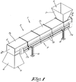
- the closed conveyor belt 1 according to the invention shown in figures 1 and 2 comprises a housing 2, which in this case is provided with an input opening 3 and an output opening 4 for the input and output respectively of the material or products to be transported.
- the input opening 3 and output opening 4 are provided with an inlet hopper 5 and outlet hopper 6 respectively. It is clear that only one or none of the two aforementioned hoppers 5, 6 can be present.
- the closed conveyor belt 1 can be used for ground or shredded plastic material for example that is produced during waste processing.
- the housing 2 is constructed from different parts, a number of which are indicated by reference figures 7a to 7d .
- the parts 7a-7d are assembled to form the housing 2.
- the housing 2 is also provided with supporting legs 8 with which the closed conveyor belt 1 can be placed on a base.
- the housing is provided with guards 10 on two opposite sides 9.
- Figure 3 shows a cross-section according to line III-III of figure 2 .
- the drive drum 12 will ensure that the conveyor belt 11 is set in motion in the direction of movement according to arrow P.
- the top track 14 moves in the direction from the input opening 3 to the output opening 4.
- the conveyor belt 11 will demarcate three zones or compartments in the housing 2: a top compartment 16 that is above the conveyor belt 11, a bottom compartment 17 that is below the conveyor belt 11, and an interspace 18 that is enclosed by the two tracks 14 and 15 of the conveyor belt 11.
- the conveyor belt 11 is provided with catches 19 that extend transversely to the direction of movement P of the conveyor belt 11.
- the catches 19 are constructed as transverse slats on the conveyor belt 11.
- the conveyor belt 11 is at least partially supported by a flat plate 20 or similar.
- top track 14 of the conveyor belt 11 is supported by means of a flat plate 20 that extends from the drive drum 12 to the return drum 13. It is possible that a flat plate 20 is also provided that is just above and against the bottom track 15.
- the flat plate 20 will ensure that the conveyor belt 11 will not sag under the weight of the material or products that are on it.
- the aforementioned flat plate 20 is supported by means of reinforcing ribs 21 or supporting slats that are provided in the interspace 18 enclosed by the conveyor belt 11, whereby the reinforcing ribs 21 or supporting slats are placed in crossed pairs. As can be seen in figure 3 , they are positioned spread over the entire length of the conveyor belt 11.
- Figure 4 shows a cross-section according to line IV-IV of figure 2 . This drawing clearly shows that the edges 22 of the conveyor belt, that extend in the direction of movement P of the conveyor belt 11, extend by a protruding section 23 through the housing 2.
- the housing 2 is provided with slots 24 to this end, through which the protruding section 23 comes out of the housing 2.
- the flat plate 20 also protrudes through the aforementioned slots 24 by its two opposite edges 25.
- the slots 24 have the shape of a type of long loop in the two opposite sides 9.
- the slot 24 is formed by cutaways being formed between the composite parts 7a-7d of the housing 2, after they have been assembled to form the housing 2, in order to form the slot 24.
- the slots 24 are formed automatically. This has the advantage that after assembling the housing 2 no slots 24 have to be made by drilling, sawing or other processes.
- guards 10 go over the protruding sections 23, 24 of the conveyor belt 11 and the flat plate 20.
- a separate guard 10 is provided for the protruding section 23 of the top track 14 and the bottom track 15. It is of course not excluded that one guard 10 is provided on each side 9 of the housing 2 that comprises both protruding sections 23, 24.
- These means 26 preferably comprise at least one seal, labyrinth seal or brush.
- the means 26 are formed by seals.
- the seals will ensure that dust and material or products of small dimensions cannot get outside through the slot 24.
- FIG. 4 clearly shows the form of the catches 19. In this case they are constructed as slats, but is it is clear that the invention is not limited to this.
- the reinforcing ribs 21 or supporting slats that are placed in crossed pairs can be clearly seen in figure 4 .
- Figure 6 shows a cross-section according to line VI-VI of figure 2 , whereby figure 7 shows a detail of figure 6 .
- the housing 2 is provided with openings 28. These openings 28 can be formed in a similar way to the slots 24 by the composite parts 7a-7d of the housing 2.
- the shafts 29 of the drums 12, 13 are affixed in the housing 2 on supports 30 provided to this end.
- means 26 are also provided that ensure a barrier between the drums 12, 13 and the openings 28 concerned in the housing 2.
- the ends 27 of the drum 12, 13 are closed off by guards 10, whereby in this case the guard 10 of the conveyor belt 11 and the guard 10 of the drums 12, 13 form a single unit on both sides of the housing 2.
- the drive means for driving the drive drum 12, such as an electric motor or similar for example, can be outside the housing 2, in the guard 10 or in the drive drum 12 itself, or otherwise.
- the operation of the closed conveyor belt 1 is very simple and as follows.
- the material to be transported such as shredded or ground plastic waste for example, can be introduced in the housing 2 on the conveyor belt 11 via the input opening 3.
- the inlet hopper 5 will provide the guide for the plastic shreds, so that all the material comes onto the top track 14 of the conveyor belt 11.
- the drive drum 12 will set the conveyor belt in motion in the direction of the arrow P, such that the material on the top track 14 will move towards the output opening 4.
- the catches 19 will hereby carry the material along as it were, which can be important when the conveyor belt 11 is placed at a shallow ascending angle, for example.
- the catches 19 will ensure that the material is held back as it were so that not everything slides to the output opening 4 at the same time, but is gradually brought to the output opening 4.
- the flat plate 20 When relatively heavy products or materials are transported with the conveyor belt 11, the flat plate 20 will ensure that the top track 14 remains nicely flat and will not sag under the influence of the weight of the products or materials. This will guarantee the good operation of the conveyor belt 11.
- the protruding parts 23 and 27 respectively of the conveyor belt 11 and drums 12, 13 will be covered by the guards 10 so that no moving parts are free during the operation of the closed conveyor belt 1. This will increase safety and can prevent damage to these moving parts.
- the outlet hopper 6 will ensure that when leaving the housing 2, the material is guided in the right direction. It is clear that the shape of the inlet hopper 5 and the outlet hopper 6 is not limited to the shapes shown in the drawings. After reversing the conveyor belt 11, the bottom track 15 will move forwards to the return drum 13 in the opposite direction to the top track 14. There the conveyor belt 11 will reverse again as it were and the process can be repeated.
- the present invention is by no means limited to the embodiments described as an example and shown in the drawings, but a closed conveyor belt according to the invention can be realised in all kinds of forms and dimensions without departing from the scope of the claims.
Description
- The present invention relates to a closed conveyor belt.
More specifically, the invention concerns a closed conveyor belt with a housing that encloses a conveyor belt that is set in motion by means of a drive.
This drive is often in the form of a drive drum or drive roller in combination with a return drum or return roller.
The conveyor belt is a long closed loop as it were that is affixed around the two aforementioned drums so that two tracks are formed in this way: a top track on which the product to be transported is laid and a bottom track that is the returning conveyor belt.
The conveyor belt moves in the housing by being driven by the drive drum.
The space between the two tracks in which both drums are located will be designated hereinafter as 'the interspace'.
Such conveyor belts are used for transporting fragile or dusty products or materials, whereby the housing will ensure that the environment around the conveyor belt is not fouled, for example by products falling from the conveyor belt onto the ground or by dust originating from the products getting into the environment. This will also contribute to better hygiene.US 2012018283 A1 discloses a closed conveyor belt according to the preamble of claim 1. -
US4674626 describes an alleged leakproof endless belt conveyor. The side edges and return end of the endless belt conveyor are sealed to prevent particulate material deposited thereon from leaking off the sides and being lost. - Such conveyor belts can also be used for hazardous products for example, as possible interaction or contact between the product and the external environment is excluded.
- In order to experience the least possible resistance when setting the conveyor belt into motion, the edge of the conveyor belt will be at a certain distance from the housing. This means that there is a certain space or clearance between the edge of the conveyor belt and the housing.
- Such known installations also present the disadvantage that products in the vicinity of the edge of the conveyor belt can fall through the aforementioned space, whereby they fall on the base of the housing below the conveyor belt or on the bottom track of the conveyor belt in the interspace between the tracks of the conveyor belt.
- This can happen for example by pouring products or materials onto the conveyor belt through an opening provided to this end in the housing.
- This not only leads to a loss of products or materials, but it also means that it is necessary to regularly clear the housing from such fouling.
- It goes without saying that this is a time-consuming job as the conveyor belt then has to be stopped and the housing has to be opened.
- It is also possible that products or materials fall at the location of the drive drum or return drum of the conveyor belt, such that these products or materials can cause faults, blockages and similar of the drums.
The material that gets onto the bottom track can also cause faults or blockages when it falls by the drum due to the movement of the conveyor belt.
Such conveyor belts also have the additional disadvantage that a lot of wear occurs.
The purpose of the present invention is to provide a solution to at least one of the aforementioned and other disadvantages. This purpose is achieved by a closed conveyor belt according to claim 1, which comprises a housing that encloses a conveyor belt that can be set in motion by means of a drive, whereby both edges of the conveyor belt, that extend in the direction of movement of the conveyor belt, extend through the housing by a protruding section that extends through slots provided to this end in the housing.
An advantage is that the products or materials that are on the conveyor belt can no longer fall from the conveyor belt onto the base of the housing or cause blockages or damage at the location of the drive. Much less wear will also occur. - For example, the drive can be constructed in the form of a drive drum and a return drum. A drive drum and return drum also means a drive roller and return roller.
- This means that there is no loss of products or materials and that the housing needs to be cleaned much less, if at all.
- Another advantage is that no material can get into the interspace between the two tracks of the conveyor belt. In other words, the aforementioned drums that are in this interspace are completely screened off from the material or product that is moved with the conveyor belt so that the drums cannot be blocked or damaged.
- It is important to note that with a conveyor belt according to the invention, there are no moving parts in the housing, in addition to the conveyor belt, the drive drum and the return drum.
- Preferably the drive is formed by a return drum and drive drum, and the ends of the return drum and/or drive drum extend through the housing through openings provided to this end in the housing.
- This has the advantage that the protruding section of the conveyor belt will be guided over the drums, so that these sections of the conveyor belt are supported by the drums. This will ensure that the conveyor belt is nicely flat without drooping edges. This will play a role in particular when the conveyor belt is made of a flexible material.
- In a practical embodiment the aforementioned protruding section of the conveyor belt and/or the protruding section of the return drum and/or drive drum are covered by a guard.
- This will ensure that the moving parts that are outside the housing are protected.
- According to a preferred characteristic of the invention, means are provided that ensure a barrier between the protruding section and the slot in the housing and/or between the drive drum and the opening concerned in the housing and/or between the return drum and the opening concerned in the housing.
- This has the advantage that dust and products or materials of small dimensions cannot come out of the housing, but are blocked by the aforementioned means. These means will also ensure that no dust and products or materials of small dimensions can get onto the base of the housing under the conveyor belt.
- The housing will as it were be completely closed off from the external environment. The interspace between the two tracks of the conveyor belt is as good as hermetically sealed in this way.
- With the intention of better showing the characteristics of the invention, a few preferred embodiments of a closed conveyor belt according to the invention are described hereinafter by way of an example, without any limiting nature, with reference to the accompanying drawings, wherein:
-
figure 1 schematically shows a perspective view of a closed conveyor belt according to the invention; -
figure 2 shows a side view offigure 1 ; -
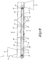
figure 3 shows a cross-section according to line III-III offigure 1 ; -
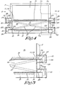
figure 4 shows a cross-section according to line IV-IV offigure 2 ; -
figure 5 shows the section indicated by F5 infigure 4 in more detail; -
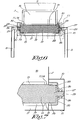
figure 6 shows a cross-section according to line VI-VI offigure 2 ; -
figure 7 shows the section indicated by F7 infigure 6 in more detail. - The closed conveyor belt 1 according to the invention shown in
figures 1 and2 comprises ahousing 2, which in this case is provided with aninput opening 3 and an output opening 4 for the input and output respectively of the material or products to be transported. - The input opening 3 and output opening 4 are provided with an
inlet hopper 5 andoutlet hopper 6 respectively. It is clear that only one or none of the twoaforementioned hoppers - Without limiting the invention to this in any way, the closed conveyor belt 1 can be used for ground or shredded plastic material for example that is produced during waste processing.
- The
housing 2 is constructed from different parts, a number of which are indicated by referencefigures 7a to 7d . The parts 7a-7d are assembled to form thehousing 2. - The
housing 2 is also provided with supportinglegs 8 with which the closed conveyor belt 1 can be placed on a base. - The housing is provided with
guards 10 on twoopposite sides 9. -
Figure 3 shows a cross-section according to line III-III offigure 2 . - This drawing clearly shows that there is a
conveyor belt 11 in thehousing 2 that is affixed around two drums or rollers, respectively adrive drum 12 and areturn drum 13. This drive drum and return drum form the drive of the conveyor belt 1. It is clear that the drive can also be constructed in a different way without departing from the scope of the invention. - As a result two tracks occur: a
top track 14 on which the product or material to be transported goes and abottom track 15 that concerns the returningconveyor belt 11. - The
drive drum 12 will ensure that theconveyor belt 11 is set in motion in the direction of movement according to arrow P. - The
top track 14 moves in the direction from the input opening 3 to the output opening 4. - At the location of the
drive drum 12 theconveyor belt 11 will reverse as it were, so that thebottom track 15 will move forwards from the output opening 4 to theinput opening 3. - The
conveyor belt 11 will demarcate three zones or compartments in the housing 2: atop compartment 16 that is above theconveyor belt 11, abottom compartment 17 that is below theconveyor belt 11, and aninterspace 18 that is enclosed by the twotracks conveyor belt 11. - Note that the
drive drum 12 and thereturn drum 13 are located in thisinterspace 18. - The
conveyor belt 11 is provided withcatches 19 that extend transversely to the direction of movement P of theconveyor belt 11. In this case thecatches 19 are constructed as transverse slats on theconveyor belt 11. - In a preferred embodiment the
conveyor belt 11 is at least partially supported by aflat plate 20 or similar. - In this case the
top track 14 of theconveyor belt 11 is supported by means of aflat plate 20 that extends from thedrive drum 12 to thereturn drum 13. It is possible that aflat plate 20 is also provided that is just above and against thebottom track 15. - The
flat plate 20 will ensure that theconveyor belt 11 will not sag under the weight of the material or products that are on it. - In this case, but not necessarily, the aforementioned
flat plate 20 is supported by means of reinforcingribs 21 or supporting slats that are provided in theinterspace 18 enclosed by theconveyor belt 11, whereby the reinforcingribs 21 or supporting slats are placed in crossed pairs. As can be seen infigure 3 , they are positioned spread over the entire length of theconveyor belt 11. -
Figure 4 shows a cross-section according to line IV-IV offigure 2 . This drawing clearly shows that theedges 22 of the conveyor belt, that extend in the direction of movement P of theconveyor belt 11, extend by a protrudingsection 23 through thehousing 2. - The
housing 2 is provided withslots 24 to this end, through which the protrudingsection 23 comes out of thehousing 2. - In such a case, but not necessarily, the
flat plate 20 also protrudes through theaforementioned slots 24 by its twoopposite edges 25. - When two
flat plates 20 are provided, this means that theinterspace 18 has no moving parts, with the exception of thedrums - The
slots 24 have the shape of a type of long loop in the twoopposite sides 9. - In such a case the
slot 24 is formed by cutaways being formed between the composite parts 7a-7d of thehousing 2, after they have been assembled to form thehousing 2, in order to form theslot 24. In other words: when assembling thehousing 2 theslots 24 are formed automatically. This has the advantage that after assembling thehousing 2 noslots 24 have to be made by drilling, sawing or other processes. - The
aforementioned guards 10 go over the protrudingsections conveyor belt 11 and theflat plate 20. In this case aseparate guard 10 is provided for the protrudingsection 23 of thetop track 14 and thebottom track 15. It is of course not excluded that oneguard 10 is provided on eachside 9 of thehousing 2 that comprises both protrudingsections - The detail in
figure 5 clearly shows that means 26 are provided that ensure a barrier between the protrudingsection 23 and theslot 24 in thehousing 2. - These means 26 preferably comprise at least one seal, labyrinth seal or brush.
- In this case the
means 26 are formed by seals. The seals will ensure that dust and material or products of small dimensions cannot get outside through theslot 24. -
Figure 4 clearly shows the form of thecatches 19. In this case they are constructed as slats, but is it is clear that the invention is not limited to this. - The reinforcing
ribs 21 or supporting slats that are placed in crossed pairs can be clearly seen infigure 4 . -
Figure 6 shows a cross-section according to line VI-VI offigure 2 , wherebyfigure 7 shows a detail offigure 6 . - It goes without saying that a similar cross-section is obtained at the location of the
other drum 12. - It can clearly be seen in
figures 6 and 7 that in this case both ends 27 of thedrums housing 2. - To this end the
housing 2 is provided withopenings 28. Theseopenings 28 can be formed in a similar way to theslots 24 by the composite parts 7a-7d of thehousing 2. - The
shafts 29 of thedrums housing 2 onsupports 30 provided to this end. - In this case means 26 are also provided that ensure a barrier between the
drums openings 28 concerned in thehousing 2. - In this case these means 26 again concern seals, but it is not excluded that use is made of labyrinth seals or brushes.
- The ends 27 of the
drum guards 10, whereby in this case theguard 10 of theconveyor belt 11 and theguard 10 of thedrums housing 2. - The drive means for driving the
drive drum 12, such as an electric motor or similar for example, can be outside thehousing 2, in theguard 10 or in thedrive drum 12 itself, or otherwise. - In the example of the drawings there is a motor outside the
housing 2. - The operation of the closed conveyor belt 1 is very simple and as follows.
- The material to be transported, such as shredded or ground plastic waste for example, can be introduced in the
housing 2 on theconveyor belt 11 via theinput opening 3. - The
inlet hopper 5 will provide the guide for the plastic shreds, so that all the material comes onto thetop track 14 of theconveyor belt 11. - The
drive drum 12 will set the conveyor belt in motion in the direction of the arrow P, such that the material on thetop track 14 will move towards the output opening 4. - The
catches 19 will hereby carry the material along as it were, which can be important when theconveyor belt 11 is placed at a shallow ascending angle, for example. When theconveyor belt 11 is placed at a shallow descending angle, thecatches 19 will ensure that the material is held back as it were so that not everything slides to the output opening 4 at the same time, but is gradually brought to the output opening 4. - When relatively heavy products or materials are transported with the
conveyor belt 11, theflat plate 20 will ensure that thetop track 14 remains nicely flat and will not sag under the influence of the weight of the products or materials. This will guarantee the good operation of theconveyor belt 11. - The protruding
parts conveyor belt 11 anddrums guards 10 so that no moving parts are free during the operation of the closed conveyor belt 1. This will increase safety and can prevent damage to these moving parts. - When the material is at the location of the
drive drum 12 it will go into the output opening 4, due to theconveyor belt 11 turning around, and leave the closed conveyor belt 1 via theoutlet hopper 6. - The
outlet hopper 6 will ensure that when leaving thehousing 2, the material is guided in the right direction. It is clear that the shape of theinlet hopper 5 and theoutlet hopper 6 is not limited to the shapes shown in the drawings.
After reversing theconveyor belt 11, thebottom track 15 will move forwards to thereturn drum 13 in the opposite direction to thetop track 14.
There theconveyor belt 11 will reverse again as it were and the process can be repeated.
The present invention is by no means limited to the embodiments described as an example and shown in the drawings, but a closed conveyor belt according to the invention can be realised in all kinds of forms and dimensions without departing from the scope of the claims.
Claims (14)
- Closed conveyor belt with a housing (2) that encloses a conveyor belt (11) that can be set in motion by means of a drive, whereby both edges (22) of the conveyor belt (11), that extend in the direction of movement (P) of the conveyor belt, extend through the housing (2) by a protruding section (23), whereby the housing is provided with guards (10) on two opposite sides (9), characterised in that the housing (2) is provided with slots (24) through which said protruding section (23) of the belt (11) extends and through which it comes out of the housing (2), whereby said guards (10) cover the protruding section (23) of the conveyor belt.
- Closed conveyor belt according to claim 1, characterised in that the drive is formed by a return drum (13) and drive drum (12) whereby the ends (27) of the return drum (13) and/or the drive drum (12) extend through the housing (2) through openings (28) provided to this end in the housing (2).
- Closed conveyor belt according to claim 1 or 2, characterised in that means (26) are provided that ensure a barrier between the protruding section (23) and the slot (24) in the housing (2) and/or between the drive drum (12) and the opening (28) concerned in the housing (2) and/or between the return drum (13) and the opening (28) concerned in the housing (2).
- Closed conveyor belt according to claim 3, characterised in that the aforementioned means (26) comprise at least one seal, labyrinth seal or brush.
- Closed conveyor belt according to any one of the previous claims characterised in that the slot (24) and/or the opening (28) are realised by the housing (2) being assembled from different parts (7a-7d), whereby cutaways are formed to form the slot (24) and/or the opening (28) between the different parts (7a-7d) after they have been assembled to form the housing (2).
- Closed conveyor belt according to any one of the previous claims 2 to 5, characterised in that the end (27) of the return drum (13) and/or drive drum (12) is closed off by a guard (10).
- Closed conveyor belt according to claim 5 and 6, characterised in that the aforementioned guards (10) form one unit.
- Closed conveyor belt according to any one of the previous claims, characterised in that the conveyor belt (11) is provided with catches (19) that extend transversely to the direction of movement (P) of the conveyor belt (11).
- Closed conveyor belt according to any one of the previous claims, characterised in that the housing (2) is provided with an input opening (3) and an output opening (4) for the input and output respectively of the material or products to be transported.
- Closed conveyor belt according to claim 9, characterised in that the input opening (3) and/or the output opening (4) are provided with an inlet hopper (5), an outlet hopper (6) respectively.
- Closed conveyor belt according to any one of the previous claims, characterised in that the drive means for driving the drive drum (12) are outside the housing (2) or in the drive drum (12) itself.
- Closed conveyor belt according to any one of the previous claims, characterised in that the conveyor belt (11) is at least partially supported by a flat plate (20) or similar.
- Closed conveyor belt according to claim 12, characterised in that the aforementioned flat plate (20) extends through the aforementioned slots (24) by two opposite edges (25).
- Closed conveyor belt according to any one of the previous claims 12 or 13, characterised in that the aforementioned flat plate (20) is supported by means of reinforcing ribs (21) or supporting slats that are provided in the interspace (18) enclosed by the conveyor belt (11), whereby the reinforcing ribs (21) or supporting slats are placed in crossed pairs.
Priority Applications (2)
| Application Number | Priority Date | Filing Date | Title |
|---|---|---|---|
| PL15001417T PL2944587T3 (en) | 2014-05-15 | 2015-05-12 | Closed conveyor belt |
| EP17155179.9A EP3184472A1 (en) | 2014-05-15 | 2015-05-12 | Closed conveyor belt |
Applications Claiming Priority (1)
| Application Number | Priority Date | Filing Date | Title |
|---|---|---|---|
| BE2014/0361A BE1021981B1 (en) | 2014-05-15 | 2014-05-15 | CLOSED TRANSPORT BAND |
Related Child Applications (3)
| Application Number | Title | Priority Date | Filing Date |
|---|---|---|---|
| EP17155179.9A Division-Into EP3184472A1 (en) | 2014-05-15 | 2015-05-12 | Closed conveyor belt |
| EP17155179.9A Division EP3184472A1 (en) | 2014-05-15 | 2015-05-12 | Closed conveyor belt |
| EP17155179.9A Previously-Filed-Application EP3184472A1 (en) | 2014-05-15 | 2015-05-12 | Closed conveyor belt |
Publications (2)
| Publication Number | Publication Date |
|---|---|
| EP2944587A1 EP2944587A1 (en) | 2015-11-18 |
| EP2944587B1 true EP2944587B1 (en) | 2018-07-11 |
Family
ID=51302577
Family Applications (2)
| Application Number | Title | Priority Date | Filing Date |
|---|---|---|---|
| EP15001417.3A Active EP2944587B1 (en) | 2014-05-15 | 2015-05-12 | Closed conveyor belt |
| EP17155179.9A Pending EP3184472A1 (en) | 2014-05-15 | 2015-05-12 | Closed conveyor belt |
Family Applications After (1)
| Application Number | Title | Priority Date | Filing Date |
|---|---|---|---|
| EP17155179.9A Pending EP3184472A1 (en) | 2014-05-15 | 2015-05-12 | Closed conveyor belt |
Country Status (5)
| Country | Link |
|---|---|
| US (1) | US9440794B2 (en) |
| EP (2) | EP2944587B1 (en) |
| BE (1) | BE1021981B1 (en) |
| ES (1) | ES2686098T3 (en) |
| PL (1) | PL2944587T3 (en) |
Families Citing this family (11)
| Publication number | Priority date | Publication date | Assignee | Title |
|---|---|---|---|---|
| AU2015215884B2 (en) * | 2014-10-28 | 2018-08-23 | Haze Ag Pty Ltd | Modular broadcast spreader |
| BE1025035B1 (en) | 2017-03-06 | 2018-10-10 | Clean Conveyor Belt BVBA | Conveyor belt system |
| CN106938774A (en) * | 2017-04-21 | 2017-07-11 | 上海怡黄木业有限公司 | For the feeding dust pelletizing system in decoration panel hot press forming technology |
| CN107857059A (en) * | 2017-12-07 | 2018-03-30 | 天津日振自动化设备有限公司 | One kind transmits stable box-type transmission equipment |
| CN110406999A (en) * | 2019-06-27 | 2019-11-05 | 张家港市华申工业橡塑制品有限公司 | A kind of wind formula dust collect plant |
| BE1027494B1 (en) | 2019-08-12 | 2021-03-16 | Clean Conveyor Belt BVBA | Conveyor belt with upright ribs |
| CN112265842A (en) * | 2020-09-24 | 2021-01-26 | 安徽华宇机械制造有限公司 | Integrated closed grain conveyor with dust removal and impurity removal functions |
| CN112676292B (en) * | 2020-12-29 | 2022-05-20 | 浙江林龙物流有限公司 | Dust separator of mechanism sand |
| CN112744618A (en) * | 2021-01-15 | 2021-05-04 | 国能信控互联技术有限公司 | Thermal power plant coal conveying belt dust fall leakage prevention intelligent system and method |
| CN113163083B (en) * | 2021-03-30 | 2022-08-30 | 盛泰光电科技股份有限公司 | Production method for camera module |
| CN114348552A (en) * | 2022-01-05 | 2022-04-15 | 中国建材国际工程集团有限公司 | Novel closed belt conveyor |
Citations (2)
| Publication number | Priority date | Publication date | Assignee | Title |
|---|---|---|---|---|
| US4674626A (en) * | 1983-12-15 | 1987-06-23 | M. L. Eakes Co. | Leakproof endless belt conveyor |
| US5762712A (en) * | 1995-08-22 | 1998-06-09 | Winkler & Dunnebier Maschinenfabrik Und Eisengiesserei Kg | Sprinkling device for metered application of super absorbing swelling substances |
Family Cites Families (14)
| Publication number | Priority date | Publication date | Assignee | Title |
|---|---|---|---|---|
| DE1041416B (en) * | 1954-11-25 | 1958-10-16 | Eickhoff Geb | Guide frame for apron conveyor |
| GB1566549A (en) * | 1976-10-25 | 1980-05-08 | Slowley S G | Conveyors |
| US4204595A (en) * | 1978-11-16 | 1980-05-27 | Amax Inc. | Adjustable conveyor belt skirtboard |
| US4321996A (en) * | 1979-05-10 | 1982-03-30 | A. O. Smith Harvestore Products, Inc. | Cleated belt forage conveyor |
| US4674627A (en) * | 1984-11-08 | 1987-06-23 | Proctor & Schwartz, Inc. | Sanitary conveyor assembly |
| US5129508A (en) * | 1991-03-25 | 1992-07-14 | Keith Shelstad | Dust control system |
| US5400897A (en) * | 1994-03-16 | 1995-03-28 | Doyle Equipment Manufacturing Company | Fertilizer conveyor |
| US5660283A (en) * | 1995-03-13 | 1997-08-26 | Groh; George John | High cleat conveyor system |
| US20020139643A1 (en) * | 2000-02-07 | 2002-10-03 | Jeff Peltier | Conveyor system |
| ES2246211T3 (en) * | 2000-04-18 | 2006-02-16 | Machinefabriek Bollegraaf Appingedam B.V. | CONVEYOR FOR THE TRANSPORTATION OF BULK MATERIALS. |
| JP2004051338A (en) * | 2002-07-23 | 2004-02-19 | Bando Chem Ind Ltd | Powdery material conveying device |
| US7673741B2 (en) * | 2005-08-08 | 2010-03-09 | Inter-Source Recovery Systems | Apparatus and method for conveying materials |
| US20120018283A1 (en) * | 2010-07-22 | 2012-01-26 | Timothy Dallner | Easy clean conveyor for food products |
| US8925718B2 (en) * | 2013-03-07 | 2015-01-06 | Engineeringology Inc. | Modular support system |
-
2014
- 2014-05-15 BE BE2014/0361A patent/BE1021981B1/en active IP Right Grant
-
2015
- 2015-05-12 EP EP15001417.3A patent/EP2944587B1/en active Active
- 2015-05-12 ES ES15001417.3T patent/ES2686098T3/en active Active
- 2015-05-12 EP EP17155179.9A patent/EP3184472A1/en active Pending
- 2015-05-12 PL PL15001417T patent/PL2944587T3/en unknown
- 2015-05-14 US US14/712,164 patent/US9440794B2/en active Active
Patent Citations (2)
| Publication number | Priority date | Publication date | Assignee | Title |
|---|---|---|---|---|
| US4674626A (en) * | 1983-12-15 | 1987-06-23 | M. L. Eakes Co. | Leakproof endless belt conveyor |
| US5762712A (en) * | 1995-08-22 | 1998-06-09 | Winkler & Dunnebier Maschinenfabrik Und Eisengiesserei Kg | Sprinkling device for metered application of super absorbing swelling substances |
Also Published As
| Publication number | Publication date |
|---|---|
| ES2686098T3 (en) | 2018-10-16 |
| EP2944587A1 (en) | 2015-11-18 |
| US20150329293A1 (en) | 2015-11-19 |
| US9440794B2 (en) | 2016-09-13 |
| EP3184472A1 (en) | 2017-06-28 |
| PL2944587T3 (en) | 2019-01-31 |
| BE1021981B1 (en) | 2016-02-01 |
Similar Documents
| Publication | Publication Date | Title |
|---|---|---|
| EP2944587B1 (en) | Closed conveyor belt | |
| KR101658829B1 (en) | Apparatus for removing scales from screw conveyer | |
| EP3006378B1 (en) | Flight conveyor | |
| US20150321852A1 (en) | Article diverting conveyor belt | |
| US9272380B2 (en) | Chip conveyer for machine tool | |
| CN204727140U (en) | A kind of multi-stage isolation formula belt scavenging machine | |
| KR101424427B1 (en) | Cleaner device for belt conveyor | |
| US20020157928A1 (en) | Slide gate for a conveyor system | |
| KR101295598B1 (en) | Crushing device for frozen ore of belt conveyor | |
| KR20190000672A (en) | Rotary chute liner and chute including this same | |
| KR101291534B1 (en) | Apparatus for removing foreign element in materials | |
| KR20160088862A (en) | Conveyor chain support | |
| KR101187763B1 (en) | Cleaner for belt conveyor | |
| US443488A (en) | Half to john b | |
| KR101330553B1 (en) | Apparatus for crushing transfer object of continuous ship unloader | |
| US614847A (en) | Endless conveyer | |
| JP4241566B2 (en) | Hopper and shell surface cleaner with hopper | |
| KR101295597B1 (en) | Apparatus for removing fallen ore of belt conveyor | |
| KR101062952B1 (en) | Falling material handling device of belt conveyor | |
| US1197060A (en) | Stable. | |
| US405045A (en) | Magnetic machine for removing mineral substances from grain | |
| JP5905279B2 (en) | Flow conveyor | |
| JP2004307090A (en) | Belt conveyor for conveying powder and granular material | |
| JP3152266U (en) | Groove cleaning device | |
| JP2009196722A (en) | Conveyor device |
Legal Events
| Date | Code | Title | Description |
|---|---|---|---|
| PUAI | Public reference made under article 153(3) epc to a published international application that has entered the european phase |
Free format text: ORIGINAL CODE: 0009012 |
|
| AK | Designated contracting states |
Kind code of ref document: A1 Designated state(s): AL AT BE BG CH CY CZ DE DK EE ES FI FR GB GR HR HU IE IS IT LI LT LU LV MC MK MT NL NO PL PT RO RS SE SI SK SM TR |
|
| AX | Request for extension of the european patent |
Extension state: BA ME |
|
| 17P | Request for examination filed |
Effective date: 20160307 |
|
| RBV | Designated contracting states (corrected) |
Designated state(s): AL AT BE BG CH CY CZ DE DK EE ES FI FR GB GR HR HU IE IS IT LI LT LU LV MC MK MT NL NO PL PT RO RS SE SI SK SM TR |
|
| 17Q | First examination report despatched |
Effective date: 20160728 |
|
| STAA | Information on the status of an ep patent application or granted ep patent |
Free format text: STATUS: EXAMINATION IS IN PROGRESS |
|
| GRAP | Despatch of communication of intention to grant a patent |
Free format text: ORIGINAL CODE: EPIDOSNIGR1 |
|
| STAA | Information on the status of an ep patent application or granted ep patent |
Free format text: STATUS: GRANT OF PATENT IS INTENDED |
|
| INTG | Intention to grant announced |
Effective date: 20180301 |
|
| GRAS | Grant fee paid |
Free format text: ORIGINAL CODE: EPIDOSNIGR3 |
|
| RAP1 | Party data changed (applicant data changed or rights of an application transferred) |
Owner name: CLEAN CONVEYOR BELT B.V.B.A. |
|
| GRAA | (expected) grant |
Free format text: ORIGINAL CODE: 0009210 |
|
| STAA | Information on the status of an ep patent application or granted ep patent |
Free format text: STATUS: THE PATENT HAS BEEN GRANTED |
|
| AK | Designated contracting states |
Kind code of ref document: B1 Designated state(s): AL AT BE BG CH CY CZ DE DK EE ES FI FR GB GR HR HU IE IS IT LI LT LU LV MC MK MT NL NO PL PT RO RS SE SI SK SM TR |
|
| REG | Reference to a national code |
Ref country code: GB Ref legal event code: FG4D |
|
| REG | Reference to a national code |
Ref country code: CH Ref legal event code: EP Ref country code: CH Ref legal event code: NV Representative=s name: ARNOLD AND SIEDSMA AG, CH |
|
| REG | Reference to a national code |
Ref country code: AT Ref legal event code: REF Ref document number: 1016652 Country of ref document: AT Kind code of ref document: T Effective date: 20180715 |
|
| REG | Reference to a national code |
Ref country code: IE Ref legal event code: FG4D |
|
| REG | Reference to a national code |
Ref country code: DE Ref legal event code: R096 Ref document number: 602015013216 Country of ref document: DE |
|
| REG | Reference to a national code |
Ref country code: NL Ref legal event code: FP |
|
| REG | Reference to a national code |
Ref country code: ES Ref legal event code: FG2A Ref document number: 2686098 Country of ref document: ES Kind code of ref document: T3 Effective date: 20181016 Ref country code: SE Ref legal event code: TRGR |
|
| REG | Reference to a national code |
Ref country code: LT Ref legal event code: MG4D |
|
| REG | Reference to a national code |
Ref country code: AT Ref legal event code: MK05 Ref document number: 1016652 Country of ref document: AT Kind code of ref document: T Effective date: 20180711 |
|
| PG25 | Lapsed in a contracting state [announced via postgrant information from national office to epo] |
Ref country code: LT Free format text: LAPSE BECAUSE OF FAILURE TO SUBMIT A TRANSLATION OF THE DESCRIPTION OR TO PAY THE FEE WITHIN THE PRESCRIBED TIME-LIMIT Effective date: 20180711 Ref country code: RS Free format text: LAPSE BECAUSE OF FAILURE TO SUBMIT A TRANSLATION OF THE DESCRIPTION OR TO PAY THE FEE WITHIN THE PRESCRIBED TIME-LIMIT Effective date: 20180711 Ref country code: BG Free format text: LAPSE BECAUSE OF FAILURE TO SUBMIT A TRANSLATION OF THE DESCRIPTION OR TO PAY THE FEE WITHIN THE PRESCRIBED TIME-LIMIT Effective date: 20181011 Ref country code: NO Free format text: LAPSE BECAUSE OF FAILURE TO SUBMIT A TRANSLATION OF THE DESCRIPTION OR TO PAY THE FEE WITHIN THE PRESCRIBED TIME-LIMIT Effective date: 20181011 Ref country code: FI Free format text: LAPSE BECAUSE OF FAILURE TO SUBMIT A TRANSLATION OF THE DESCRIPTION OR TO PAY THE FEE WITHIN THE PRESCRIBED TIME-LIMIT Effective date: 20180711 Ref country code: GR Free format text: LAPSE BECAUSE OF FAILURE TO SUBMIT A TRANSLATION OF THE DESCRIPTION OR TO PAY THE FEE WITHIN THE PRESCRIBED TIME-LIMIT Effective date: 20181012 Ref country code: AT Free format text: LAPSE BECAUSE OF FAILURE TO SUBMIT A TRANSLATION OF THE DESCRIPTION OR TO PAY THE FEE WITHIN THE PRESCRIBED TIME-LIMIT Effective date: 20180711 Ref country code: IS Free format text: LAPSE BECAUSE OF FAILURE TO SUBMIT A TRANSLATION OF THE DESCRIPTION OR TO PAY THE FEE WITHIN THE PRESCRIBED TIME-LIMIT Effective date: 20181111 |
|
| PG25 | Lapsed in a contracting state [announced via postgrant information from national office to epo] |
Ref country code: HR Free format text: LAPSE BECAUSE OF FAILURE TO SUBMIT A TRANSLATION OF THE DESCRIPTION OR TO PAY THE FEE WITHIN THE PRESCRIBED TIME-LIMIT Effective date: 20180711 Ref country code: LV Free format text: LAPSE BECAUSE OF FAILURE TO SUBMIT A TRANSLATION OF THE DESCRIPTION OR TO PAY THE FEE WITHIN THE PRESCRIBED TIME-LIMIT Effective date: 20180711 Ref country code: AL Free format text: LAPSE BECAUSE OF FAILURE TO SUBMIT A TRANSLATION OF THE DESCRIPTION OR TO PAY THE FEE WITHIN THE PRESCRIBED TIME-LIMIT Effective date: 20180711 |
|
| REG | Reference to a national code |
Ref country code: DE Ref legal event code: R097 Ref document number: 602015013216 Country of ref document: DE |
|
| PG25 | Lapsed in a contracting state [announced via postgrant information from national office to epo] |
Ref country code: RO Free format text: LAPSE BECAUSE OF FAILURE TO SUBMIT A TRANSLATION OF THE DESCRIPTION OR TO PAY THE FEE WITHIN THE PRESCRIBED TIME-LIMIT Effective date: 20180711 Ref country code: CZ Free format text: LAPSE BECAUSE OF FAILURE TO SUBMIT A TRANSLATION OF THE DESCRIPTION OR TO PAY THE FEE WITHIN THE PRESCRIBED TIME-LIMIT Effective date: 20180711 Ref country code: EE Free format text: LAPSE BECAUSE OF FAILURE TO SUBMIT A TRANSLATION OF THE DESCRIPTION OR TO PAY THE FEE WITHIN THE PRESCRIBED TIME-LIMIT Effective date: 20180711 |
|
| PLBE | No opposition filed within time limit |
Free format text: ORIGINAL CODE: 0009261 |
|
| STAA | Information on the status of an ep patent application or granted ep patent |
Free format text: STATUS: NO OPPOSITION FILED WITHIN TIME LIMIT |
|
| PG25 | Lapsed in a contracting state [announced via postgrant information from national office to epo] |
Ref country code: SK Free format text: LAPSE BECAUSE OF FAILURE TO SUBMIT A TRANSLATION OF THE DESCRIPTION OR TO PAY THE FEE WITHIN THE PRESCRIBED TIME-LIMIT Effective date: 20180711 Ref country code: SM Free format text: LAPSE BECAUSE OF FAILURE TO SUBMIT A TRANSLATION OF THE DESCRIPTION OR TO PAY THE FEE WITHIN THE PRESCRIBED TIME-LIMIT Effective date: 20180711 Ref country code: DK Free format text: LAPSE BECAUSE OF FAILURE TO SUBMIT A TRANSLATION OF THE DESCRIPTION OR TO PAY THE FEE WITHIN THE PRESCRIBED TIME-LIMIT Effective date: 20180711 |
|
| 26N | No opposition filed |
Effective date: 20190412 |
|
| PG25 | Lapsed in a contracting state [announced via postgrant information from national office to epo] |
Ref country code: SI Free format text: LAPSE BECAUSE OF FAILURE TO SUBMIT A TRANSLATION OF THE DESCRIPTION OR TO PAY THE FEE WITHIN THE PRESCRIBED TIME-LIMIT Effective date: 20180711 |
|
| PG25 | Lapsed in a contracting state [announced via postgrant information from national office to epo] |
Ref country code: MC Free format text: LAPSE BECAUSE OF FAILURE TO SUBMIT A TRANSLATION OF THE DESCRIPTION OR TO PAY THE FEE WITHIN THE PRESCRIBED TIME-LIMIT Effective date: 20180711 |
|
| PG25 | Lapsed in a contracting state [announced via postgrant information from national office to epo] |
Ref country code: LU Free format text: LAPSE BECAUSE OF NON-PAYMENT OF DUE FEES Effective date: 20190512 |
|
| PG25 | Lapsed in a contracting state [announced via postgrant information from national office to epo] |
Ref country code: PT Free format text: LAPSE BECAUSE OF FAILURE TO SUBMIT A TRANSLATION OF THE DESCRIPTION OR TO PAY THE FEE WITHIN THE PRESCRIBED TIME-LIMIT Effective date: 20181111 |
|
| PG25 | Lapsed in a contracting state [announced via postgrant information from national office to epo] |
Ref country code: CY Free format text: LAPSE BECAUSE OF FAILURE TO SUBMIT A TRANSLATION OF THE DESCRIPTION OR TO PAY THE FEE WITHIN THE PRESCRIBED TIME-LIMIT Effective date: 20180711 |
|
| PG25 | Lapsed in a contracting state [announced via postgrant information from national office to epo] |
Ref country code: MT Free format text: LAPSE BECAUSE OF FAILURE TO SUBMIT A TRANSLATION OF THE DESCRIPTION OR TO PAY THE FEE WITHIN THE PRESCRIBED TIME-LIMIT Effective date: 20180711 Ref country code: HU Free format text: LAPSE BECAUSE OF FAILURE TO SUBMIT A TRANSLATION OF THE DESCRIPTION OR TO PAY THE FEE WITHIN THE PRESCRIBED TIME-LIMIT; INVALID AB INITIO Effective date: 20150512 |
|
| PG25 | Lapsed in a contracting state [announced via postgrant information from national office to epo] |
Ref country code: MK Free format text: LAPSE BECAUSE OF FAILURE TO SUBMIT A TRANSLATION OF THE DESCRIPTION OR TO PAY THE FEE WITHIN THE PRESCRIBED TIME-LIMIT Effective date: 20180711 |
|
| P01 | Opt-out of the competence of the unified patent court (upc) registered |
Effective date: 20230516 |
|
| PGFP | Annual fee paid to national office [announced via postgrant information from national office to epo] |
Ref country code: NL Payment date: 20230526 Year of fee payment: 9 Ref country code: IT Payment date: 20230519 Year of fee payment: 9 Ref country code: IE Payment date: 20230529 Year of fee payment: 9 Ref country code: FR Payment date: 20230525 Year of fee payment: 9 Ref country code: ES Payment date: 20230601 Year of fee payment: 9 Ref country code: DE Payment date: 20230530 Year of fee payment: 9 Ref country code: CH Payment date: 20230610 Year of fee payment: 9 |
|
| PGFP | Annual fee paid to national office [announced via postgrant information from national office to epo] |
Ref country code: TR Payment date: 20230426 Year of fee payment: 9 Ref country code: SE Payment date: 20230527 Year of fee payment: 9 Ref country code: PL Payment date: 20230419 Year of fee payment: 9 |
|
| PGFP | Annual fee paid to national office [announced via postgrant information from national office to epo] |
Ref country code: BE Payment date: 20230529 Year of fee payment: 9 |
|
| PGFP | Annual fee paid to national office [announced via postgrant information from national office to epo] |
Ref country code: GB Payment date: 20230529 Year of fee payment: 9 |