EP2937617A1 - Liaison rotative doté d'une limitation d'angle de rotation - Google Patents
Liaison rotative doté d'une limitation d'angle de rotation Download PDFInfo
- Publication number
- EP2937617A1 EP2937617A1 EP14001479.6A EP14001479A EP2937617A1 EP 2937617 A1 EP2937617 A1 EP 2937617A1 EP 14001479 A EP14001479 A EP 14001479A EP 2937617 A1 EP2937617 A1 EP 2937617A1
- Authority
- EP
- European Patent Office
- Prior art keywords
- stop
- rotation
- rotatable connection
- relative
- axial direction
- Prior art date
- Legal status (The legal status is an assumption and is not a legal conclusion. Google has not performed a legal analysis and makes no representation as to the accuracy of the status listed.)
- Granted
Links
Images


Classifications
-
- F—MECHANICAL ENGINEERING; LIGHTING; HEATING; WEAPONS; BLASTING
- F16—ENGINEERING ELEMENTS AND UNITS; GENERAL MEASURES FOR PRODUCING AND MAINTAINING EFFECTIVE FUNCTIONING OF MACHINES OR INSTALLATIONS; THERMAL INSULATION IN GENERAL
- F16M—FRAMES, CASINGS OR BEDS OF ENGINES, MACHINES OR APPARATUS, NOT SPECIFIC TO ENGINES, MACHINES OR APPARATUS PROVIDED FOR ELSEWHERE; STANDS; SUPPORTS
- F16M11/00—Stands or trestles as supports for apparatus or articles placed thereon Stands for scientific apparatus such as gravitational force meters
- F16M11/20—Undercarriages with or without wheels
- F16M11/2007—Undercarriages with or without wheels comprising means allowing pivoting adjustment
-
- A—HUMAN NECESSITIES
- A61—MEDICAL OR VETERINARY SCIENCE; HYGIENE
- A61B—DIAGNOSIS; SURGERY; IDENTIFICATION
- A61B50/00—Containers, covers, furniture or holders specially adapted for surgical or diagnostic appliances or instruments, e.g. sterile covers
- A61B50/10—Furniture specially adapted for surgical or diagnostic appliances or instruments
-
- A—HUMAN NECESSITIES
- A61—MEDICAL OR VETERINARY SCIENCE; HYGIENE
- A61B—DIAGNOSIS; SURGERY; IDENTIFICATION
- A61B50/00—Containers, covers, furniture or holders specially adapted for surgical or diagnostic appliances or instruments, e.g. sterile covers
- A61B50/20—Holders specially adapted for surgical or diagnostic appliances or instruments
- A61B50/24—Stands
-
- F—MECHANICAL ENGINEERING; LIGHTING; HEATING; WEAPONS; BLASTING
- F16—ENGINEERING ELEMENTS AND UNITS; GENERAL MEASURES FOR PRODUCING AND MAINTAINING EFFECTIVE FUNCTIONING OF MACHINES OR INSTALLATIONS; THERMAL INSULATION IN GENERAL
- F16C—SHAFTS; FLEXIBLE SHAFTS; ELEMENTS OR CRANKSHAFT MECHANISMS; ROTARY BODIES OTHER THAN GEARING ELEMENTS; BEARINGS
- F16C11/00—Pivots; Pivotal connections
- F16C11/04—Pivotal connections
- F16C11/10—Arrangements for locking
-
- F—MECHANICAL ENGINEERING; LIGHTING; HEATING; WEAPONS; BLASTING
- F16—ENGINEERING ELEMENTS AND UNITS; GENERAL MEASURES FOR PRODUCING AND MAINTAINING EFFECTIVE FUNCTIONING OF MACHINES OR INSTALLATIONS; THERMAL INSULATION IN GENERAL
- F16M—FRAMES, CASINGS OR BEDS OF ENGINES, MACHINES OR APPARATUS, NOT SPECIFIC TO ENGINES, MACHINES OR APPARATUS PROVIDED FOR ELSEWHERE; STANDS; SUPPORTS
- F16M11/00—Stands or trestles as supports for apparatus or articles placed thereon Stands for scientific apparatus such as gravitational force meters
- F16M11/02—Heads
- F16M11/04—Means for attachment of apparatus; Means allowing adjustment of the apparatus relatively to the stand
- F16M11/06—Means for attachment of apparatus; Means allowing adjustment of the apparatus relatively to the stand allowing pivoting
- F16M11/08—Means for attachment of apparatus; Means allowing adjustment of the apparatus relatively to the stand allowing pivoting around a vertical axis, e.g. panoramic heads
-
- F—MECHANICAL ENGINEERING; LIGHTING; HEATING; WEAPONS; BLASTING
- F16—ENGINEERING ELEMENTS AND UNITS; GENERAL MEASURES FOR PRODUCING AND MAINTAINING EFFECTIVE FUNCTIONING OF MACHINES OR INSTALLATIONS; THERMAL INSULATION IN GENERAL
- F16M—FRAMES, CASINGS OR BEDS OF ENGINES, MACHINES OR APPARATUS, NOT SPECIFIC TO ENGINES, MACHINES OR APPARATUS PROVIDED FOR ELSEWHERE; STANDS; SUPPORTS
- F16M11/00—Stands or trestles as supports for apparatus or articles placed thereon Stands for scientific apparatus such as gravitational force meters
- F16M11/20—Undercarriages with or without wheels
- F16M11/2007—Undercarriages with or without wheels comprising means allowing pivoting adjustment
- F16M11/2014—Undercarriages with or without wheels comprising means allowing pivoting adjustment around a vertical axis
-
- F—MECHANICAL ENGINEERING; LIGHTING; HEATING; WEAPONS; BLASTING
- F16—ENGINEERING ELEMENTS AND UNITS; GENERAL MEASURES FOR PRODUCING AND MAINTAINING EFFECTIVE FUNCTIONING OF MACHINES OR INSTALLATIONS; THERMAL INSULATION IN GENERAL
- F16M—FRAMES, CASINGS OR BEDS OF ENGINES, MACHINES OR APPARATUS, NOT SPECIFIC TO ENGINES, MACHINES OR APPARATUS PROVIDED FOR ELSEWHERE; STANDS; SUPPORTS
- F16M13/00—Other supports for positioning apparatus or articles; Means for steadying hand-held apparatus or articles
- F16M13/02—Other supports for positioning apparatus or articles; Means for steadying hand-held apparatus or articles for supporting on, or attaching to, an object, e.g. tree, gate, window-frame, cycle
- F16M13/027—Ceiling supports
-
- F—MECHANICAL ENGINEERING; LIGHTING; HEATING; WEAPONS; BLASTING
- F16—ENGINEERING ELEMENTS AND UNITS; GENERAL MEASURES FOR PRODUCING AND MAINTAINING EFFECTIVE FUNCTIONING OF MACHINES OR INSTALLATIONS; THERMAL INSULATION IN GENERAL
- F16M—FRAMES, CASINGS OR BEDS OF ENGINES, MACHINES OR APPARATUS, NOT SPECIFIC TO ENGINES, MACHINES OR APPARATUS PROVIDED FOR ELSEWHERE; STANDS; SUPPORTS
- F16M2200/00—Details of stands or supports
- F16M2200/02—Locking means
- F16M2200/021—Locking means for rotational movement
- F16M2200/024—Locking means for rotational movement by positive interaction, e.g. male-female connections
-
- Y—GENERAL TAGGING OF NEW TECHNOLOGICAL DEVELOPMENTS; GENERAL TAGGING OF CROSS-SECTIONAL TECHNOLOGIES SPANNING OVER SEVERAL SECTIONS OF THE IPC; TECHNICAL SUBJECTS COVERED BY FORMER USPC CROSS-REFERENCE ART COLLECTIONS [XRACs] AND DIGESTS
- Y10—TECHNICAL SUBJECTS COVERED BY FORMER USPC
- Y10T—TECHNICAL SUBJECTS COVERED BY FORMER US CLASSIFICATION
- Y10T403/00—Joints and connections
- Y10T403/32—Articulated members
- Y10T403/32254—Lockable at fixed position
- Y10T403/32262—At selected angle
- Y10T403/32319—At selected angle including pivot stud
- Y10T403/32327—At selected angle including pivot stud including radially spaced detent or latch component
- Y10T403/32336—Engaging notch or recess in outer periphery of component
-
- Y—GENERAL TAGGING OF NEW TECHNOLOGICAL DEVELOPMENTS; GENERAL TAGGING OF CROSS-SECTIONAL TECHNOLOGIES SPANNING OVER SEVERAL SECTIONS OF THE IPC; TECHNICAL SUBJECTS COVERED BY FORMER USPC CROSS-REFERENCE ART COLLECTIONS [XRACs] AND DIGESTS
- Y10—TECHNICAL SUBJECTS COVERED BY FORMER USPC
- Y10T—TECHNICAL SUBJECTS COVERED BY FORMER US CLASSIFICATION
- Y10T403/00—Joints and connections
- Y10T403/32—Articulated members
- Y10T403/32549—Articulated members including limit means
Definitions
- the present invention relates to a rotatable connection for a tripod device for placement in an operating room having an adjustable stop mechanism which is arrangeable between a spindle and a sleeve rotatably mounted relative to the spindle about a rotation axis and is arranged, at least two different relative rotational angles of the spindle relative to the sleeve or to define at least two different rotational ranges, wherein the adjustable stop mechanism comprises: a first part, in particular in the form of a stop ring, which is rotatably mounted on the spindle storable and has at least one stop; and a second part, which is provided against rotation on the bushing; wherein the first part is rotatably mounted relative to the second part.
- the present invention relates in particular to a rotatable connection with individual features of claim 1 and a support system or a stand device with individual features of the corresponding further independent claim.
- Tripods in particular ceiling stands such as ceiling supply units, monitor support, or so-called spring arms or central axes, usually have one or more with respect to a vertical position rigidly arranged or height-adjustable support by means of which a medical device attached thereto can be moved and positioned, for example in one Operating room, especially in intensive care.
- Supply units are often mounted on the tripods with which medical-electrical terminals can be supplied with the media required during an operation, for example.
- the carriers define an operating radius of the medical device in which the medical device is positioned.
- the carriers can usually be rotated at least by at least one rotatable connection, in particular a rotary joint.
- the carriers are also adjustable in height and / or pivotable about an axis oriented at least approximately horizontally in height.
- a rotational movement of individual carriers should in many cases be limited to a predetermined angle. This can be avoided, for example, that a carrier is rotated by more than 360 ° relative to another carrier and thereby twisted in the carrier lines are twisted, squeezed or even demolished.
- a rotation angle limitation can be provided, for example, in the form of a stop on which a carrier strikes at a specific angle of rotation, for example 300 °.
- the stop can be mounted, for example, fixed to the carrier, in particular in the form of a introduced in the radial direction securing bolt. The stop specifies a predefined angle of rotation.
- rotation angle limitation can ensure that a maximum rotation angle is not exceeded, but usually also has the disadvantage that the freedom of movement of the tripod is limited, so that, for example, a supply unit of the tripod can not be arranged in any position.
- the range of action of the tripod is limited, in particular without consideration of a specific room situation. Therefore, it must be considered in each individual case, by which stop the rotation angle limitation can or should be defined.
- the correct interpretation of the rotation angle limitation, in particular an adequate positioning of the stop can already bring difficulties in the production of a respective tripod, especially if it is not clear at which location the tripod is to be used in each case. Therefore, rotational angle limitations are practical, by means of which a rotational angle or a rotational position can be subsequently adapted.
- a device with an adjustable angle of rotation is out of the EP 2 325 541 B1 known.
- a two-part adjustable stop mechanism in which an annular member may be selectively positioned outwardly about a circumference of a first bracket of the first bracket, and the annular member has a plurality of end-face recesses or projections by which it relative to the first carrier in a simple manner in different rotational angle positions can be arranged.
- a stop On the annular part, a stop is also arranged, on which a second carrier can strike. By means of the annular part, a rotation angle of the two carriers can be adjusted relative to each other.
- the stop mechanism is arranged within a collar of the second carrier.
- the annular member may be formed by engaging a tool in an outer shell surface of the annular member circumferential groove are raised to position the annular member relative to the first carrier in a desired rotational angular position. Further, another annular member is provided on the first carrier, which can be positioned relative to the annular member.
- the two annular parts are arranged inside the collar and are enclosed and covered radially on the outside by the collar. In the collar, a locking bolt inserted in the radial direction is arranged, which rests in a gap formed between the two annular parts. The relative rotational position of the first part relative to the second part defines the extent of the gap in the circumferential direction.
- the stop mechanism is arranged substantially on the first carrier and cooperates with the second carrier via the radially introduced securing bolt.
- the object is also to provide a stand device with a rotation angle limitation, in which individual carriers of the stand device can be positioned in an operating room in a flexible manner thanks to an adjustable rotatable connection.
- a stop device By an arrangement of the stopper mechanism on both the first connection component and the second connection component, a stop device can be provided which is arranged in a simple manner between the two connection components and can be repositioned, in particular by axial displacement of the first part relative to the second part.
- the entire stop mechanism is composed of only three components, in particular the first part, the second part and the stop device.
- connection or mounting of the first part to or on the connection component can in this case be used e.g. be provided by two abutting or engageable with each other projections, so a positive connection.
- the first part is arranged rotatable about the axis of rotation, in particular together with the first connecting member.
- the first part may be twisted during engagement with the first connecting member, e.g. can be ensured by a stop in the form of a bolt or locking pin.
- a Verwarblockierbare arrangement may thus comprise an arrangement in which between the respective part and the respective connecting member, although a relative rotational movement is possible, which is limited by any stop from a certain angle of rotation.
- a relative rotational movement between the part and the connecting element is then no longer possible in the corresponding direction of rotation.
- the first part can not be rotated further around the first connection component, at least in one direction of rotation.
- a rotation angle range in particular with a rotation angle greater than 360 °, can be set.
- a twist-lockable arrangement may also comprise a twist-proof arrangement, e.g. a tongue and groove connection.
- connection or mounting of the second part to or on the connection component described as a torsion-proof arrangement can be provided, for example, by a tongue and groove connection, that is to say a connection which defines only a single relative position of the two components relative to one another.
- a non-rotating arrangement, connection or storage can also include an arrangement in which the second part (in one piece) as a integral part of the connecting member is formed.
- the second part can be integrated into a second connecting component designed as a socket.
- the first part is preferably mounted so as to be rotationally lockable on the first connecting component, this is preferably only with regard to a rotational movement.
- the twist-lockable assembly does not necessarily bring a predefined axial position with it.
- the first part is preferably mounted on the second connecting component in the axial direction, in particular by means of the stop device and / or the second part.
- the first connection component in the axial direction can preferably be positioned axially on the second connection component, or vice versa, e.g. by means of a shaft securing ring.
- a rotatable connection is preferably to be understood an arrangement by means of which a rotation of two components to each other by a predetermined angle can be ensured.
- the rotatable connection is e.g. a connection between a bushing and a spindle, wherein the rotatable connection does not necessarily comprise the bushing and spindle, but e.g. only the camp or storage space provided for it.
- the rotatable connection preferably has at least one rotary joint or forms part of the rotary joint.
- a hinge is to be understood preferably a joint which allows at least one rotation about one or more axes of rotation, wherein a translational degree of freedom can be realized.
- the hinge is preferably located at the interface between two individual carriers, but may also partition a single carrier into multiple sections.
- the hinge can e.g. be provided at the interface between a spindle and a socket.
- a tripod device is preferably a device for holding, stationary placement and / or moving at least one medical device to understand that on a wall (in a wall storage) or a ceiling or at the bottom of an operating room or any other space for medical purposes firmly mounted can be, for example, a ceiling tripod.
- the stand device is then not completely freely displaced in the operating room, but can be displaced only in a certain radius of action, in particular relative to a arranged on a ceiling or wall of the operating room attachment point or mounting point.
- the tripod device can as on a Ceiling mounted ceiling supply unit be formed and have one or more supply brackets, which is mounted on one or two support arms and positionable.
- the tripod device can also be designed as a monitor carrier.
- the stand device can also be designed as a so-called, in particular mounted on a wall spring arm and, for example, have a light.
- the stand device can also be designed as a so-called, in particular mounted on a ceiling central axis and have a plurality of support systems, each having at least one carrier on which, for example, a monitor or a lamp is mounted.
- the tripod device need not necessarily be fixedly mounted on a wall, but may also be mounted on a mobile substructure.
- the mobile substructure can be positioned in space by means of brakes, for example. Also in this case, an adjustable stop mechanism is useful.
- An adaptable stop mechanism here is preferably to be understood as meaning any device which can limit a rotation angle and / or rotation range of a carrier, in particular relative to another carrier or relative to a fixed (fictitious) axis of rotation, e.g. a through a fixed mounting point on a wall of a room extending axis of rotation.
- the adjustable stop mechanism at least also has a form-fitting connection or is designed for positive engagement.
- the adjustable stop mechanism can also act non-positively.
- the range of rotation is preferably an angular range in which a carrier can be rotated relative to another carrier or to a wall.
- the angular range may e.g. 330 ° or more than 360 °.
- the angular range can be constantly large, but e.g. with respect to different circumferential positions, e.g. from 0 ° to 300 ° with respect to a north direction, or from 30 ° to 330 ° with respect to the north direction.
- the range of rotation can be defined by the different angular positions.
- the first part is preferably a part to understand, which is somehow frehblockierbar coupled to the rotational movement of the first connecting member (eg a spindle) and preferably cooperates positively with the first connecting member.
- the first Part is preferably displaceable in the axial direction relative to the first connecting member. In the circumferential direction, a relative displacement is blocked to one another or blocked from a certain angle of rotation.
- the first part may, for example, be annular and then be referred to as a stop ring, which defines at least one stop. In this case, a stop is to be understood as meaning any projection or shoulder projecting in particular also in the axial direction.
- the second part is preferably a part to understand, which is rotationally coupled to the rotational movement of the second connecting member (eg a socket) and, for example, cooperates positively with the second connecting member, in particular rotationally synchronous.
- the second part is provided on the second connection component such that the second part and the second connection component in any case execute the same rotational movement.
- the position of the second part relative to the second connecting member is then predefined and also not changeable.
- the second part may be formed by the second connection component, for example, be cast.
- the second part is fixedly provided on the second connection component, that is to say also axially fixed, ie not displaceable in the axial direction relative to the second connection component.
- the second part is preferably connected only to the second connection component or formed thereby and is decoupled from the first connection component and interacts only indirectly by means of the stop device and the first part with the first connection component.
- the second part may for example be annular and may have at least one positive-locking contour in the form of a toothing, for example a sawtooth contour, in particular at the interface to the stop device.
- the second part can then be called a sprocket.
- no stops or counterstops defining a range of rotation are arranged on the second part. Such stops are not required, in particular because a relative rotational movement between the second part and the stop device does not have to take place or should.
- the second part is arranged to store the stop device rotationally fixed in an adjustable rotational position on the second connecting component, so that a stop of the first part can abut against the stop device in order to transmit a correspondingly caused reaction force from the stop device to the second part.
- the first part is preferably only indirectly connected to the second part, in particular via the stop device.
- stop means is preferably a part to understand which is adapted to provide a counter-stop in a relative to one of the connecting components, in particular relative to the second connecting member, fixed position, wherein a circumferentially on the stopper exercised (twisting) force, ie a torque can be transmitted via the counter-stop between the connecting components.
- the stop means is preferably arranged to prevent a direct interaction between the first and second part.
- the stop means is preferably interposed between the first and second parts and arranged to transmit a torque between the first part and the second part.
- the stop device extends at least partially around the axis of rotation around, wherein the stop device is preferably annular and is provided circumferentially around the axis of rotation.
- the stop means may then be e.g. be described as a collar.
- a counter stop is preferred to understand any projection, paragraph or a protruding nose.
- first and second part are preferably to be understood an arrangement in which the first and second parts are not coupled directly to each other, but only indirectly by means of the stopper.
- An arrangement “axially between” means preferably that the first part does not have to engage in the axial direction in the second part, but that engagement or cooperation of the first part with the second part (alone) can be ensured by means of the stop means.
- rotational angular position is preferably a relative rotational position of a carrier relative to another adjacent carrier or with respect to a fixed aligned in space in a defined direction axis to understand.
- the rotational angle position can also be described in terms of an absolute (horizontal) angle, e.g. around a (fictitious) vertically oriented axis of rotation.
- the stop means is adapted to transmit a circumferentially acting rotational force exerted on the stop or the counter stop between the first and second part, ie from the first part to the second part and / or from the second part to the first part ,
- the anchor device is set up To couple the two parts together, in particular to define a certain range of rotation angle of the parts relative to each other.
- the stop device can be positioned against rotation of one of the two parts, in particular the second part, on one of the two parts in at least two different rotational angle positions.
- a starting point or starting point of a specific rotation angle range can be set, in particular with a rotation angle greater than 360 °.
- the counter-stop is fixedly positioned on the stop device.
- the counter-abutment may be integrally provided on the stop means, that is, the stop means forms an integral part with the counter-stop.
- the counter-stop or at least one counter-stop of a plurality of counter-stops may also be attached to the stop means, e.g. by means of a screw connection in the radial or axial direction. This facilitates e.g. the setting of a certain angle of rotation.
- the first part is arranged to be displaceable in the axial direction along the axis of rotation.
- the stop device can be moved together with the first part in a simple manner in the axial direction in order to set the rotation range or angle of rotation. It is not necessary to remove any radially engaging bolt or a bolt receiving collar to displace the two parts relative to each other in the axial direction.
- the first part can be guided via a centering on an inner circumferential surface on the second connecting component.
- the stop device is arranged to be displaceable in the axial direction along the axis of rotation, in particular together with the first part.
- This allows the setting of the rotatable connection done in a simple manner. In this case, e.g. only the stopper to be taken, and the first part can be moved axially together with the stop means, in particular up against a gravitational force.
- the first part and the second part and the stop means are arranged in the axial direction in series one behind the other.
- an adjustment of the rotation range can be made in a simple manner.
- a damping element between the parts or one of the parts and the stop device can be provided in a simple manner.
- the arrangement in series one behind the other also allows easy installation. As an arrangement in series one behind the other is to be understood an arrangement in which (apart from a possibly interposed damping element) of the first part of the stop means comes to rest, and wherein the stop means comes to rest on the second part.
- the stop device is arranged in the axial direction between the two parts and overlaps in the axial direction of the second part in the region of a positive contour and overlaps in the axial direction of the first part in the region of the stop.
- the stopper mechanism can be provided in the form of a simply constructed plug-in system. Also, a good stability of the arrangement can be ensured, in particular because the first part and the stop device can stabilize against tilting, special on the inner and / or outer circumferential surface of the stopper.
- the first part is dimensioned and geometrically designed such that the first part, in particular the at least one stop, can be arranged at least partially outside the stop device and / or at least partially within the stop device.
- This arrangement allows an arrangement of the at least one counter stop on an outer or inner circumferential surface of the stop means, whereby a force can be passed in the circumferential direction.
- the counter-attack can be made particularly robust and solid.
- the first part and / or the second part at least partially extends around the axis of rotation, wherein the first part and / or the second part is preferably annular and is provided circumferentially around the axis of rotation.
- the first part is annular and has two or more stops, which are arranged opposite to each other and projecting in the axial direction of a disc of the first part, in particular on an outer circumferential surface or annular surface.
- the first part may have a rotationally symmetrical, in particular disk-like region.
- a slice is to be understood as meaning preferably a largely planar part which extends substantially in a plane oriented in the radial direction, with a significantly smaller extent in an axial direction orthogonal to the plane.
- An embodiment as a disk has the advantage that a sliding surface can be provided in a simple manner on a respective end face of the disk.
- the first part and the stop device and optionally also the second part in the axial direction on the second connecting member are axially arranged or axially positioned or stored.
- at least the first part and the stop device are positioned axially on the second connecting component in the axial direction solely on the basis of the weight force.
- the stop device is arranged such that a rotationally secure arrangement of the stop device on the second part (in particular exclusively) is ensured by a weight force or gravitational force acting on the stop device.
- a weight force or gravitational force acting on the stop device In this case, only a displacement of the stop device against a weight force acting on the stop device must take place for adjusting the stop mechanism, in particular together with the first part. It is not necessary to remove any radially inserted locking pins or screws. Rather, an axial securing of the first part can take place by means of a securing ring.
- the second part has a form-fitting contour for fixing the individual rotational angle positions, in particular on an inwardly directed lateral surface and / or on an end face pointing in the axial direction.
- the stop device has a form-fitting contour corresponding thereto, in particular on an axial direction to the second part or second connection member facing end side. In this way, an easily accessible connector can be provided, by means of which the stop mechanism can be adjusted or adjusted.
- a toothing or tooth contour or a contour with regular shoulders or projections is to be understood as a form-fitting contour.
- the shape of a single tooth is largely arbitrary.
- the single tooth has the shape of a cuboid or, seen in cross-section, the shape of a rectangle.
- the form-fitting contour is not necessarily exclusively form-fitting, but may also be non-positive.
- the form-fitting contour is preferably not materially bonded to ensure that the at least one counter-stop is reversible and can be positioned as often as desired in different rotational angle positions.
- the form-fitting contour of the second part is preferably accessible in an axial direction at least approximately parallel to the axis of rotation such that the stop device with the corresponding form-fitting contour can be pushed onto the second part in the axial direction. This facilitates both the assembly and the setting.
- the form-fitting contour of the second part and the positive-locking contour of the stop device are each designed as a toothed rim, with teeth of the toothed ring preferably projecting in an axial direction at least approximately parallel to the axis of rotation.
- a sprocket is preferably a rotationally symmetrical with respect to the axis of rotation formed contour with a plurality of individual teeth, in which the teeth are arranged at a uniform distance from each other.
- the design as a sprocket provides e.g. the advantage of small adjustment steps, because the more teeth are provided, the finer the starting point or starting point of the rotation angle range can be defined, e.g. in 10 ° increments.
- the first part and the stop device together form a bearing, in particular a sliding bearing.
- the first part rests on the stop device.
- the first part can be displaced relative to the stop device or to the second part in a low-friction manner, even if the contact surface between the first part and the stopper acts a normal force on the contact surface.
- the normal force does not have to be large, for example, it can correspond to the weight of the first part.
- a smooth rotatable connection can be provided by the bearing, and the interaction of the individual components of the rotatable connection can be optimized.
- the stop means is arranged between the first part and the second part, that the first part is in contact only with the stop means, but not with the second part.
- the second part is also in contact only with the stop device.
- the first part (preferably only) interacts with the second part by means of the stop device.
- the first part has a sliding surface arranged on an end face, in particular on an end face pointing towards the stop device, and is set up to rotate in a sliding manner with the sliding surface on the stop device.
- the stop device may have a sliding face arranged on an end face, in particular on an end face pointing towards the first part or facing away from the second connecting member, and be arranged to support the first part by means of the sliding face for a sliding rotational movement about the axis of rotation.
- the sliding surface of the first part and / or the sliding surface of the stop device may preferably be e.g. be completely circumferentially formed as a circular ring surface, or even in sections.
- the bearing for the second part can be provided in a simple and cost-effective manner.
- a robust stop mechanism can be provided, which can be operated manually in a simple manner.
- the intermeshing of the components, ie the first part, the stop ring and the second part can be ensured solely on the basis of the gravitational force.
- the flat bearing on annular end surfaces can ensure an exact positioning of the components relative to each other and make the rotatable connection very robust and smooth running.
- a sliding surface is preferably a surface to understand, which has a low coefficient of friction for sliding friction, either because of a particularly low roughness or a particularly smooth surface, either because of a low-friction Materials with lubricating properties.
- a material for the stop device or the adjusting ring for example, zinc die casting can be used, either with or without coating.
- the stop device is designed as a collar with a frontally projecting in the axial direction in the direction of the second part form-fitting contour.
- the adjusting ring is preferably a rotationally symmetrical part (apart from any stops), which can be positioned in different rotational angular positions, e.g. each offset by 15 °, so e.g. in 24 different angles of rotation.
- the stop device is a one-piece, in the axial direction attachable to the second part part, on which the at least one counter-stop preferably protrudes in the radial direction, in particular of an outer or inner circumferential surface of the stop device.
- the space requirement in the axial direction (the required height) can be kept low and a flat design can be realized.
- the adjustable stop mechanism is configured to set a rotation range with a relative rotation angle greater than 360 °, in particular in the range of 360 ° to 420 °.
- the angle of rotation greater than 360 ° can be ensured, in particular, by the fact that the first part is not secured against rotation or rotation, but is arranged only torsion-lockable on the first connecting component.
- the first part has a form-locking element, to which an anti-rotation, eg a bolt, of the first connection component can come to rest.
- the positive-locking element in contrast to the stop of the first part) is decoupled from the stop device, ie, does not interact with the stop device together, at least not with respect to a coupled rotational movement.
- the starting point or starting point for the rotational movement or the rotational angle range can be defined.
- the relatively large angle of rotation of more than 360 °, in particular up to 420 °, for example, provides the advantage of great flexibility.
- the stops can be positioned without adversely affecting the freedom of movement of the tripod device.
- rotatable connections usually only a rotary (angle) range is set with a smaller angle of rotation of about 330 ° maximum be, or setting the rotation angle range is not possible or only in a very complex manner.
- the adjustable stop mechanism has a damping element, in particular made of elastomeric material, which corresponds to the second part and / or the stop device, in particular a form-fitting contour of the stop device projecting from the front side in the axial direction.
- the damping element can prevent a swinging back or spring back of the carrier in a sudden abutment of the stops to each other.
- a damping element is preferably a rubber element to understand with a matched to the respective positive contour geometry.
- the damping element may e.g. have the shape of a meander.
- the damping element can be arranged as an insert or jacket on the second part or on the stop device, in particular on a respective form-fitting contour.
- the rotatable connection to an intermediate element which is seen in the axial direction between the first part, in particular between the stopper, and the second connecting member is arranged and at least one positive contour for rotationally fixed connection with the stop means or the second connecting member, wherein in each case a form-fitting contour is preferably arranged on two opposite end faces of the intermediate element.
- the stop mechanism arranged on the two connecting components can be made even more flexible, and can be provided in a simple manner, in particular also in the case of molded bushes.
- the form-fitting contour can ensure an anti-rotation of other elements, such as a slip ring inner part.
- the intermediate element can also provide advantages in terms of manufacturing characteristics.
- the form-fitting contour can be introduced on the second part in a simpler manner, especially on a ring portion of a forked bushing. For example, it can be dispensed with a costly die-casting tool.
- an intermediate element is preferably an element to understand, which can be coupled positively against rotation both with the stopper and with the second part.
- the intermediate element is an optionally provided, additional part to which a positive contour can be provided in a particularly simple manner, preferably on an end face.
- the intermediate element may e.g. also be provided for manufacturing reasons.
- a mechanical processing of the intermediate element, in particular the introduction of the positive contour (s), can be done in a simple manner.
- the intermediate element can be handled easily and has easily accessible surfaces.
- the (respective) form-fitting contour is preferably formed by grooves, which extend in the radial direction. The grooves may extend along the entire intermediate element.
- the benefits may be provided in sections (as short grooves) in combination with springs.
- the intermediate element is formed as a disc, in particular annular disc.
- the intermediate member may be arranged in series with the other components around the first connecting member.
- the flat construction as a disk can also ensure a small footprint in the axial direction.
- the intermediate element is wedge-shaped with a non-uniform axial dimension or thickness relative to the axial direction.
- the rotatable connection can be used in a simple manner in conjunction with a molded socket, on which a Entformungsschräge is provided.
- the Entformungsschräge be compensated, so that the two parts and the stopper can be arranged axially aligned with each other.
- the wedge-shaped geometry is set up to compensate for a draft angle of the socket.
- a support system for a tripod device for placement in an operating room and for positioning a medical device in the operating room, which rotatable connection according to the invention and the first connecting member, in particular in the form of a spindle, and the second connecting member, in particular Shape of a socket.
- the support system are preferably those components of the tripod device to understand, which at least partially assume a function for holding and positioning of the medical device.
- the support system may comprise a plurality of preferably relatively movable each other preferably rigid arms or carriers and a plurality of levers, joints or bearings.
- the medical device preferably comprises any control panel and / or any display device for displaying e.g. Patient data on.
- the second connection component is designed as a socket, in particular a fork-shaped socket, wherein at least the stop device and the second part and preferably also the first part are arranged in the socket, in particular between two ring sections of the socket, preferably in one of the two ring sections.
- the rotatable connection preferably has an intermediate element which is inserted into the bush, in particular into one of the two ring sections.
- a rotatable connection can be provided whose stop device is easily accessible, which facilitates the setting of the angle of rotation or angle of rotation range.
- the individual components can be easily inserted into the socket, in particular from the side in the radial direction.
- an additional intermediate element in the socket in particular in one of the two ring sections, are inserted, in particular to compensate for a Entformungsschräge and / or to enable a simple or cost-effective production of the positive contours.
- the individual components can also be displaced in a simple manner in the axial direction relative to one another in order to set the angle of rotation or rotational range.
- a stand device for placement in an operating room and for positioning a medical device in the operating room, which comprises a rotatable connection according to the invention or the above-described support system with the rotatable connection according to the invention.
- the stand device in particular individual carriers relative to one another, can be positioned in a flexible manner.
- the counter-abutment can be displaced in the second part to establish a suitable rotational angular position, in particular with respect to a specific arrangement of the tripod device relative to other components in the operating theater.
- a carrier is preferably a boom or support arm to understand, which extends in a particular direction and can ensure the desired range of action for the different nominal positions of the medical device, in particular by a rotational movement about a rotatable connection.
- the carrier can optionally also be pivoted in height and / or translationally displaced in height.
- the carrier may also be a telescopic device with an (additional) degree of freedom of movement in translational direction along the longitudinal axis of the carrier.
- the carrier may be at least partially e.g. be formed by a continuous casting, in particular an aluminum extruded profile.
- the stop device is a rotation range or an amount of rotation angle of the rotatable connection, in particular a permissible relative angle of rotation of the two connecting components to each other definable.
- the second part is arranged on or on one of the carriers in the region of the rotatable connection.
- a contour or a stop can be fixedly fixed to one of the carriers, with which the carrier can be positioned in the different rotational angle positions with respect to the other carrier or with respect to any other stationarily arranged part.
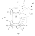
- a rotatable connection 1 is shown, which is arranged on a stand device 100 about a rotation axis R.
- the stand device 100 has a support system 101 with a first support 102 and at least one further support (not explicitly shown).
- the rotatable connection 1 has a first connection component 10, in particular in the form of a spindle, and a second connection component 20, in particular in the form of a socket.
- the first carrier 102 is mounted around the first connecting member 10 and connected to the second connecting member 20.
- the bushing 20 can be described as being fork-shaped and has two bushings 21, each arranged in a ring section 22 of the bushing 20, through which the first connecting component 10 is passed.
- a cavity is formed, which is manually accessible in the radial direction, in particular for adjusting a stop mechanism 30.
- the axial position of the sleeve 20 on the spindle 10 can be defined by means of a spindle secured to the shaft shaft or by a shaft nut.
- the rotatable connection 1 has an adjustable stop mechanism 30, which is arranged between the spindle 10 and the sleeve 20.
- the stop mechanism 30 has a first part 40 and a second part 50.
- the first part 40 is formed in the embodiment shown as a stop ring, and the second part 50 as Sprocket (cf. FIG. 3B ).
- the ring gear 50 is disposed within the sleeve 20, in particular on an inner circumferential surface of one of two annular portions of the fork-shaped bushing 20.
- the stop ring 40 has a plurality of stops 42 which project on an end face of the stop ring 40 in the axial direction. The stops 42 are fixedly positioned on the stop ring 40.
- a stop means 60 is arranged, which forms part of the adjustable stop mechanism 30.
- the stop device 60 is formed in the embodiment shown as an adjusting ring
- the adjusting ring 60 has a plurality of counter-stops 62, which are arranged on an outer circumferential surface of the adjusting ring 60 and projecting in the radial direction.
- the counterstops 62 are stationarily positioned on the adjusting ring 60.
- the stops 42 and the counterstops 62 each have at least one flat side surface 42.1, 62.1 (cf. Fig. 3 . 4 ), which preferably extend at least approximately in a plane which is parallel to the axis of rotation R.
- the flat side surfaces 42.1, 62.1 form stop surfaces on which the stops 42, 62 can come into contact with one another when the stop ring 40 is rotated relative to the adjusting ring 60.
- the flat side surfaces 42.1, 62.1 correspond to one another.
- the adjusting ring 60 can be positioned relative to the sleeve in different rotational angular positions against rotation on the socket, which in connection with the FIGS. 3A and 3B will be described in more detail.
- the stop ring 40 can be mounted torsionally lockable on the spindle 10.
- the spindle 10 is at least partially formed as a hollow shaft.
- a rotation 13 in particular a bolt, arranged, which can ensure that the stop ring 40 only in a certain rotation (angle) can rotate range relative to the spindle 10.
- the stop ring 40 has a form-locking element 43 which corresponds to the bolt 13 and which is arranged on an inner side of the stop ring 40.
- a dead angle can be bridged, which arises, for example, due to the extension of the stop or counter-stop in the circumferential direction.
- a verfinable rotation range with a rotation angle greater than 330 °, or even greater than 360 °, in particular up to 420 °.
- a verfinierbarer stop ring 40 may also be referred to as an intermediate ring, which bridges a blind spot and is operatively disposed between the spindle 10 and the counter-stops 62.
- the spindle 10 has a groove 11 for receiving a locking ring 80.
- the locking ring 80 can prevent the stop ring 40 is displaced in the axial direction upwards.
- the stop ring 40 has a (second) end face 47, which can come to rest on the retaining ring 80.
- the locking ring 80 can be easily removed to adjust the rotatable connection 1.
- the stop ring 40 can be moved upwards, and then the adjusting ring 60 is moved so far up until the collar 60 is no longer in the socket 20 and the (not shown in detail, formed inside the sleeve 20) sprocket 50th then, the adjusting ring 60 is rotated, and is moved in another rotational angular position back down and is brought into engagement with the sleeve 20 and the sprocket 50.
- the retaining ring 80 is not necessarily required.
- the adjustable stop mechanism can also be adjusted without any locking screws or rings.
- the adjusting ring 60 has a diameter which is smaller than a pitch circle, on which the stops 42 are arranged, and which is larger than a pitch circle, on which the positive-locking element 43 is arranged.
- the stop ring 40 surrounds the adjusting ring 60 in the radial direction with the relative to the adjusting ring 60 inside positive locking element 43 and the relative to the collar 60 outer stops 42.
- the inner diameter of an inner circumferential surface of the adjusting ring 60 is significantly larger than the outer diameter of an outer circumferential surface the spindle 10.
- the adjusting ring 60 is not mounted on the spindle 60. Rather, the adjusting ring 60 can be centered from the outside on its outer circumferential surface on the second part 50 and in the sleeve 20.
- the stop ring 40 can be centered over the stops 42 on the outer circumferential surface of the adjusting ring 60. A centering on the spindle 10 is not required. This can ensure relative rotational movement with little friction.
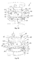
- FIG. 3A is the rotatable connection 1 shown in an arrangement in which the rotational angle position can be adjusted.
- the adjusting ring 60 has been displaced in the axial direction upward after the locking ring 80 has been removed or released from the corresponding groove.
- the adjusting ring 60 is arranged to be displaceable in the axial direction along the axis of rotation R, in particular together with the stop ring 40.
- the adjusting ring 60 and the stop ring 40 are arranged in series one behind the other in the axial direction and engage in one another in the axial direction.
- the positive-locking contour 64 is formed as a toothing which projects in the axial direction.
- the form-fitting contour 64 has a multiplicity of individual teeth 64. 1, which are arranged at a constant spacing on a partial circle in the circumferential direction on an underside of the adjusting ring 60.
- the adjusting ring 60 can be positioned against rotation to the (not visible) second part or ring gear in at least two different rotational angle positions.
- a damping element (not shown, only in FIGS. 11 and 12 shown), which between the positive contour 64 and the in FIG. 3B shown the positive contour 54 of the second part 50 can act.
- the damping element can be formed, for example, as a meander-shaped ring made of an elastomer whose geometry corresponds to the geometry of the teeth 64.1.
- the adjusting ring 60 has three counter-stops 62 (two of which are visible), which are arranged at an angle of about 120 ° in the circumferential direction offset from each other.
- three stops 42 are provided on the stop ring 40, which are arranged offset at an angle of about 120 ° in the circumferential direction to each other.
- the form-locking element 43 is arranged at a circumferential position at least approximately centrally between two of the three stops 42. This arrangement of the stops 42, 62 and the positive-locking element 43 relative to one another can in particular also ensure a favorable load distribution.
- a disc-shaped portion 41 of the stop ring 40 is shown.
- the three stops 42 project in the axial direction from the disk-shaped portion 41.
- the stops each have a concave or concave inwardly curved inner surface 42.2, by means of which they can come to an outer circumferential surface 60.1 (with at least approximately the same radius of curvature) of the adjusting ring 60 to the plant.
- the positive locking element 43 has a convex or convexly outwardly curved outer surface 43.1, by means of which the positive-locking element 43 on an inner lateral surface 60.2 (with at least approximately the same radius of curvature) of the adjusting ring 60 can come to rest. In this way, a relative rotational movement without tilting and by sliding abutting and mutual guiding or centering done.
- the adjusting ring 60 can be verkuppelt with the socket 20.
- the positive-locking contour 54 is arranged on an inwardly directed lateral surface 20.2 of the bushing 20 and protrudes inward in the radial direction.
- the form-fitting contour 54 has a plurality of individual teeth 54.1, which are arranged at a constant distance on a pitch circle in the circumferential direction on the lateral surface 20.2.
- the adjusting ring 60 can be arranged in a cavity radially between the spindle 10 and the bushing 20, and the rotation or the bolt 13 protrudes into a cavity formed radially between the spindle 10 and the adjusting ring 60, in which also the positive-locking element 43 can be arranged displaced is.
- the adjusting ring 60 can be arranged in the radial direction between the positive-locking element 43 and the stops 42.
- the stop ring 40 can come to rest with a (first) end face 46 on a corresponding end face 66 of the adjusting ring 60 and can slide on it during a relative rotational movement.
- the end face 46 in this case has an annular sliding surface section (or a bearing), which (or which) is arranged between the stops 42 and the form-locking element 43.
- the adjusting ring 60 forms a bearing for the stop ring 40, in particular a sliding bearing.
- the end face 66 for example, also have a coating with a low coefficient of friction, or the adjusting ring 60 may be at least partially made of a corresponding material. The same applies to the stop ring 40 and the surfaces 42.2 and 43.1 and 46.
- the force acting on the end face 66 is not great: the stop ring 40 has only a relatively small weight. A frictional force between the stop ring 40 and the adjusting ring 60 can be almost negligible in this arrangement.
- the end faces 46, 66 or corresponding sections can also be referred to as sliding surfaces or sliding surface sections.
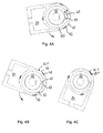
- the operation of the stop mechanism can be with reference to the FIGS. 4A, 4B and 4C in a few words also be described as follows: the spindle 10 (and thus also the fixed in the spindle 10 radial pin 13) forms a fixed component, and the sleeve 20, however, the movable component.
- the socket 20 With a displacement of a carrier (not shown), the socket 20, starting from the in FIG. 4A shown relative position relative to the spindle 10 is rotated counterclockwise until the positive locking element 43 of the stop ring (of which in the cross-sectional view shown only the hatching 42 and the form-locking element 43 are visible) on the radial bolt 13, here corresponding to a twist angle of about 330 °.
- the adjusting ring 60 is arranged against rotation on the sleeve 20 and rotates with the same extent as the sleeve 20. From the in the FIG. 4B shown pivot point may be a relative movement between the stop ring and the adjusting ring 60, in particular, the adjusting ring 60 can slide under the stop ring relative to the stop ring and further rotated until the corresponding counter-stop 62 abuts with the side surface 62.1 on the corresponding side surface of the stop 42 of the stop ring, which In this embodiment, a relative rotation of another 90 ° allows.
- a centering 45 of the stop ring 40 is indicated, by means of which the stop ring 40 with respect to the spindle 10 can be centered.
- the centering 45 may be formed by an inner circumferential surface or a portion of an inner circumferential surface of the stop ring 40.
- the inner circumferential surface does not necessarily have the same diameter as the outer circumferential surface of the spindle 10, but the diameter may also be slightly larger to allow a simple relative displacement with little friction, be it in the circumferential direction or in the axial direction.
- the centering 45 may also be formed by an inwardly facing surface portion of the positive locking element 43, which can be more effectively ensured that no axial tilting of the stop ring 40 on the spindle 10.
- the centering 45 need not ensure the arrangement of the stop ring 40 alone. Rather, it can optionally (additionally) be provided. A centering can already be done alone by the concave inner surface 42.2 of the stop ring 40 on the adjusting ring 60, wherein the adjusting ring 60 in turn may be centered on the second part. These possibilities of centering provide a simply constructed arrangement with exactly relative to each other can be arranged components.
- a specific rotation range can be achieved with a rotation angle greater than 360 °, in particular a rotation angle in the range of 360 ° to 420 °.
- an intermediate element 70 which has a first form-fitting contour 74 on one end face (as shown on the upper side) and a second form-fitting contour 75 on another end face (as shown on the underside).
- the positive contours 74, 75 each have individual grooves 74.1, 75.1.
- the grooves 75.1 arranged on a first end face 76 extend in the radial direction.
- the grooves 75.1 are preferably arranged at a uniform angle to each other, so seen in the circumferential direction in a uniform distance from each other.
- the grooves 74.1 arranged on a second end face 77 extend linearly in a straight line and are preferably aligned parallel to one another.
- the grooves 74.1 preferably have a uniform distance from each other.
- the intermediate element 70 is annular, and the end faces 76, 77 are planar.
- the intermediate element 70 is designed as an annular disc.
- the intermediate element 70 is shown in a side view. From the FIG. 6 shows that the first end face 76 is arranged at an angle ⁇ to the second end face 77, corresponding to the inclination of a Entformungsschräge.
- the angle ⁇ is preferably in the range of 1.5 °.
- the end faces 76, 77 are not parallel.
- the intermediate element 70 is wedge-shaped, in particular as a wedge-shaped annular disc. In this way, a draft angle of the socket can be compensated, which in connection with the FIG. 7 will be described in more detail.
- the end face 76 preferably corresponds to that end face which is verkuppelt with the adjusting ring 60.
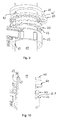
- FIG. 7 an embodiment is shown in which, in a modification to that in the FIGS. 1 to 3B shown embodiment in the FIGS. 5 and 6 shown intermediate element 70 is provided.
- the intermediate element 70 is arranged in the axial direction between the bushing 20 and the adjusting ring 60.
- the intermediate element 70 is inserted into the socket 20.
- the intermediate element 70 can be pushed onto one of the ring sections 22 of the bush 20, as shown FIG. 8 seen.
- the radially oriented grooves 75.1 correspond to the individual teeth 64.1 of the adjusting ring 60.
- grooves 74.1 or longitudinal ribs on the second end face correspond to a corresponding positive contour of the second part, which ( not visible) is disposed within the sleeve 20 and is preferably formed by the sleeve 20 itself.
- Longitudinally extending grooves or recesses can be formed in a simple or cost-effective manner in the sleeve 20, in particular simpler than radially oriented grooves.
- the socket 20 may e.g. be executed as a casting.
- the bush 20 preferably has a draft angle, in particular also in the region of the positive-locking contour of the second part, which can be provided by the bushing 20.
- the Entformungsschräge is provided to remove the finished molded socket 20 from a mold can. If the bushing is designed as a casting, a draft angle can not be dispensed with readily (without costly design measures).
- the intermediate element 70 end faces 76, 77 which are arranged at an angle ⁇ corresponding to the angle of the Gusschräge to each other.
- the intermediate element 70 may, on the one hand, make it possible for the positive-fit contour of the second part to be introduced in a simple manner into the second part or into the socket.
- a strictly axial arrangement of the individual components relative to one another can also be ensured in the case of a socket designed as a casting.
- the intermediate member 70 therefore allows the rotatable connection to be provided and designed in a simple and cost effective manner, even with molded bushes.
- a tab 61 is formed on the adjusting ring 60 on an outer circumferential surface of the adjusting ring 60, of which a counter-stop 62 protrudes in the axial direction upwards to the stop ring 40 out.
- the counter-stop 62 is designed as a kind of bolt.
- the stop ring 40 has on the disk-shaped portion 41 on an outer circumferential surface on a tab 41.1, which protrudes in the radial direction and forms a stop 42. Nonetheless, in the embodiment of FIGS FIG. 7 in modification to it also according to the in the FIGS. 1 to 3B shown variants are provided.
- the stop ring 40 is rotatably connected to the spindle 10. A relative rotational movement between the spindle 10 and the stop ring 40 is thereby prevented.
- the intermediate element 70 can be pushed onto a ring portion 22 of the bushing 20 before the bushing 20 is arranged on the spindle 10.
- the lower (second) end face 77 on which the rectilinear grooves 74.1 oriented parallel to one another are arranged, faces the annular section 22.
- corresponding grooves may be provided which form the positive-locking contour 54.
- the stop ring 40 is not only torsionally, but against rotation and also mounted axially displaceably on the spindle 10.
- the corresponding anti-rotation 13 is designed here as a groove formed in the outer circumferential surface of the spindle 10, in which the positive-locking element 43 engages.
- the ring section 22 has an end face 22.1 for receiving the intermediate element 70.
- the end face 22.1 points into a cavity formed between the two ring sections.
- the positive contour 54 is formed.
- the ring portion 22 includes the second part. The second part is integrated in the ring section 22.
- the damping element 90 is a rubber element with a geometry adapted to the respective form-fitting contour.
- the damping element has the shape of a meander.
- FIG. 12 is an adjustable stop mechanism 30 with an arrangement with a spindle 10 and a socket 20 comparable to in the FIG. 3B shown arrangement shown.
- damping element 90 is arranged between the collar 60 and the second part 50 between the collar 60 and the second part 50 .
- the arrangement between the adjusting ring 60 and the second part 50 has the advantage that no relative movement must take place on the damping element 90.
- a form-fitting contour 94 on the damping element 90 is formed on both end faces of the damping element 90.
- the positive-locking contour 94 has a toothing geometry with teeth 94.1 and 94.2 in both axial directions.
- the positive-locking contour 94 corresponds both with the positive-locking contour 54 of the second part 50 and with the positive-locking contour 64 of the adjusting ring 60.
- the damping element 90 is in the form of an insert or as a jacket surrounding the positive-locking contour 54 or 64 on the second part 50 or on the adjusting ring 60 arranged.
Priority Applications (4)
| Application Number | Priority Date | Filing Date | Title |
|---|---|---|---|
| EP14001479.6A EP2937617B1 (fr) | 2014-04-24 | 2014-04-24 | Liaison rotative doté d'une limitation d'angle de rotation |
| CN201510202461.1A CN105020549B (zh) | 2014-04-24 | 2015-04-24 | 具有旋转角度限制装置的可旋转连接装置 |
| US14/695,372 US10260673B2 (en) | 2014-04-24 | 2015-04-24 | Rotatable connection with rotational angle limitation |
| US16/380,064 US11512809B2 (en) | 2014-04-24 | 2019-04-10 | Rotatable connection with rotational angle limitation |
Applications Claiming Priority (1)
| Application Number | Priority Date | Filing Date | Title |
|---|---|---|---|
| EP14001479.6A EP2937617B1 (fr) | 2014-04-24 | 2014-04-24 | Liaison rotative doté d'une limitation d'angle de rotation |
Publications (2)
| Publication Number | Publication Date |
|---|---|
| EP2937617A1 true EP2937617A1 (fr) | 2015-10-28 |
| EP2937617B1 EP2937617B1 (fr) | 2017-03-01 |
Family
ID=50628610
Family Applications (1)
| Application Number | Title | Priority Date | Filing Date |
|---|---|---|---|
| EP14001479.6A Active EP2937617B1 (fr) | 2014-04-24 | 2014-04-24 | Liaison rotative doté d'une limitation d'angle de rotation |
Country Status (3)
| Country | Link |
|---|---|
| US (2) | US10260673B2 (fr) |
| EP (1) | EP2937617B1 (fr) |
| CN (1) | CN105020549B (fr) |
Cited By (6)
| Publication number | Priority date | Publication date | Assignee | Title |
|---|---|---|---|---|
| US20150377283A1 (en) * | 2014-04-24 | 2015-12-31 | Ondal Medical Systems Gmbh | Rotatable connection with limited rotational angle |
| EP3244122A1 (fr) * | 2016-05-12 | 2017-11-15 | Tragfreund GmbH | Dispositif de support |
| US10247352B2 (en) | 2014-04-24 | 2019-04-02 | Ondal Medical Systems Gmbh | Rotatable connection with a rotational angle limitation |
| US10260673B2 (en) | 2014-04-24 | 2019-04-16 | Ondal Medical Systems Gmbh | Rotatable connection with rotational angle limitation |
| US10760611B2 (en) | 2014-04-24 | 2020-09-01 | Ondal Medical Systems Gmbh | Rotatable connection having rotational angle limitation |
| CN111878505A (zh) * | 2020-08-18 | 2020-11-03 | 东莞市劲丰电子有限公司 | 可变圆心的水滴形内折齿轮转动机构 |
Families Citing this family (16)
| Publication number | Priority date | Publication date | Assignee | Title |
|---|---|---|---|---|
| US9945498B2 (en) | 2013-12-27 | 2018-04-17 | Stryker Corporation | Multi-stage rotary overtravel stop |
| DE102017002578A1 (de) * | 2017-03-16 | 2018-09-20 | Man Truck & Bus Ag | Abklappvorrichtung für ein Spiegelersatzsystem |
| US10995872B1 (en) * | 2017-10-25 | 2021-05-04 | Lyndon J. Hurley | Pivoting support assembly |
| CN111578077A (zh) * | 2017-12-25 | 2020-08-25 | 胡张艳 | 一种便于移动的稳定型医用升降台 |
| EP3518014B1 (fr) * | 2018-01-30 | 2020-11-18 | Leica Instruments (Singapore) Pte. Ltd. | Dispositif d'équilibrage et procédé d'équilibrage d'un microscope |
| US10851938B2 (en) | 2018-04-02 | 2020-12-01 | Humanscale Corporation | Adjustable support arm |
| FR3087516B1 (fr) * | 2018-10-19 | 2021-12-10 | Akwel | Dispositif de raccordement instantane. |
| CN109552672B (zh) * | 2018-11-12 | 2021-12-17 | 上海宇航系统工程研究所 | 一种硬限位角度可调的限位机构 |
| CN109404414A (zh) * | 2018-12-01 | 2019-03-01 | 陆英豪 | 一种旋转子母扣 |
| CN111281431B (zh) * | 2018-12-06 | 2023-06-13 | 深圳迈瑞生物医疗电子股份有限公司 | 一种转动装置及乳腺机 |
| US11274787B2 (en) * | 2019-05-30 | 2022-03-15 | Alcon Inc. | Stopping element for limiting rotational range of a rotating part |
| CN110065090A (zh) * | 2019-06-04 | 2019-07-30 | 苏州博众机器人有限公司 | 一种快速装拆组件、机器人、快速安装方法及快速拆卸方法 |
| CN110319109A (zh) * | 2019-06-11 | 2019-10-11 | 利亚德智慧显示(深圳)有限公司 | 拼弧装置及显示屏 |
| DE102019209556A1 (de) * | 2019-06-28 | 2020-12-31 | Ford Global Technologies, Llc | Befestigungsvorrichtung für ein verstellbares Zubehörteil |
| EP3906884A1 (fr) * | 2020-05-04 | 2021-11-10 | F.A.R.O. FABBRICA APPARECCHIATURE RAZIONALI ODONTOIATRICHE S.p.A. | Lampe de service |
| EP4098833A1 (fr) * | 2021-05-31 | 2022-12-07 | dormakaba Deutschland GmbH | Tringlerie actionneur de porte |
Citations (5)
| Publication number | Priority date | Publication date | Assignee | Title |
|---|---|---|---|---|
| FR1341061A (fr) * | 1962-11-20 | 1963-10-25 | Quarzlampen Gmbh | Scialytique à bras articulés |
| DE3808327A1 (de) | 1987-03-21 | 1988-09-29 | Krause Robert Gmbh Co Kg | Schwenkarmvorrichtung |
| EP0392303A1 (fr) * | 1989-03-31 | 1990-10-17 | Heraeus Instruments GmbH | Dispositif d'éclairage chirurgical |
| DE102008011129A1 (de) * | 2008-02-26 | 2009-08-27 | Berchtold Holding Gmbh | Aufhängung |
| EP2325541B1 (fr) | 2009-11-18 | 2013-05-22 | Ondal Medical Systems GmbH | Mécanisme d'arrêt ajustable pour connexion rotative |
Family Cites Families (59)
| Publication number | Priority date | Publication date | Assignee | Title |
|---|---|---|---|---|
| US392303A (en) * | 1888-11-06 | banta | ||
| US1634922A (en) | 1924-04-18 | 1927-07-05 | American Motor Body Corp | Revolving chair |
| US3133743A (en) | 1962-11-08 | 1964-05-19 | Trayer Products Inc | Idler arm thrust bearing assembly |
| US3713618A (en) | 1971-03-22 | 1973-01-30 | Krueger Metal Products | Self centering support |
| US4303135A (en) | 1977-08-18 | 1981-12-01 | Benoit Lloyd F | Directional drilling sub |
| US4673154A (en) | 1983-07-05 | 1987-06-16 | Karapita Alexander D | Suspension device |
| US4587908A (en) | 1985-03-12 | 1986-05-13 | Amerock Corporation | Rotary shelf assembly with bearing assembly and detent mechanism |
| CA1290952C (fr) | 1986-10-11 | 1991-10-22 | Kenneth H. Wenzel | Joint universel d'arbre pour moteur a fond de forage |
| FR2616399B1 (fr) | 1987-12-09 | 1989-10-20 | Ecia Equip Composants Ind Auto | Dispositif pour assurer le reglage fin du calage de l'orientation angulaire d'un volant sur un arbre de direction d'automobile |
| US5123768A (en) | 1991-08-06 | 1992-06-23 | Franklin Ronald D | Articulating positioning device for tools |
| DE4306802C1 (de) | 1993-03-04 | 1994-08-04 | Kreuzer Gmbh & Co Ohg | Deckenstativ |
| DE19510752C1 (de) | 1995-03-24 | 1996-07-11 | Heraeus Med Gmbh | Drehgelenk |
| US5720570A (en) | 1995-12-28 | 1998-02-24 | Lite Specialty Metal Works, Inc. | Dental chair attachment |
| ATE229627T1 (de) | 1996-01-24 | 2002-12-15 | Heraeus Med Gmbh | Operationsleuchte mit drehlager zur befestigung eines schwenkarms |
| US6079949A (en) | 1998-11-13 | 2000-06-27 | Lasko Holdings, Inc. | Ratchet assembly for pedestal fan |
| US6633328B1 (en) | 1999-01-05 | 2003-10-14 | Steris Corporation | Surgical lighting system with integrated digital video camera |
| US6234259B1 (en) | 1999-05-06 | 2001-05-22 | Vector Magnetics Inc. | Multiple cam directional controller for steerable rotary drill |
| US6226068B1 (en) | 1999-08-27 | 2001-05-01 | Amphenol Corporation | Self-locking bayonet coupling mechanism |
| US6639623B2 (en) | 1999-12-23 | 2003-10-28 | Hill-Rom Services, Inc. | Controls for a surgical theater system |
| US6698704B2 (en) | 2000-08-17 | 2004-03-02 | Mavig Gmbh | Fixing device |
| GB2376484B (en) | 2001-06-12 | 2005-08-03 | Pilot Drilling Control Ltd | Improvements to steerable downhole tools |
| ES2242893T3 (es) | 2001-11-05 | 2005-11-16 | Steris Inc. | Sistema medico de suspension con dos arboles giratorios. |
| US7922671B2 (en) | 2002-01-30 | 2011-04-12 | Natus Medical Incorporated | Method and apparatus for automatic non-cooperative frequency specific assessment of hearing impairment and fitting of hearing aids |
| US20050242261A1 (en) | 2002-02-25 | 2005-11-03 | Steris Inc | Surgical suspension system |
| JP4133834B2 (ja) | 2002-02-25 | 2008-08-13 | ステリス インコーポレイテッド | 無影灯のための周辺照明システム |
| ATE340944T1 (de) | 2003-04-29 | 2006-10-15 | Trumpf Kreuzer Med Sys Gmbh | Feststellbremse und medizinisches deckenstativ mit einer solchen feststellbremse |
| US20050006542A1 (en) | 2003-07-11 | 2005-01-13 | Henning Gerald W. | Flat panel monitor support arm |
| WO2005021986A1 (fr) | 2003-08-27 | 2005-03-10 | Ergotron, Inc. | Joint de verrouillage pour bras de support |
| ATE425402T1 (de) | 2003-09-25 | 2009-03-15 | Philmac Pty Ltd | Befestigungsring für eine drehkupplung für rohrleitungen |
| WO2006002997A1 (fr) | 2004-07-06 | 2006-01-12 | Tracto-Technik Gmbh | Tete de forage d'un engin a forer le sol |
| US20060285915A1 (en) | 2005-06-01 | 2006-12-21 | Norgren Automotive, Inc. | Apparatus for incrementally adjusting a modular tooling coupling |
| BRPI0520637A2 (pt) | 2005-09-29 | 2009-05-19 | Yancu Solomovitz Brief | braço mecánico multidirecional articulado para suportar e suspender objetos para uso mão livre |
| US7559518B2 (en) | 2005-10-05 | 2009-07-14 | Kye Systems Corp. | Support for a computer peripheral device |
| US7452088B2 (en) * | 2006-03-07 | 2008-11-18 | Velvac, Incorporated | Mirror with adjustable detent |
| US7591446B2 (en) | 2006-10-12 | 2009-09-22 | Spirit Aerosystems, Inc. | Swivel bracket system |
| DE102006055940A1 (de) | 2006-11-24 | 2008-06-12 | Rittal Gmbh & Co. Kg | Kupplungsteil eines Tragarmsystems |
| AU2008226408B2 (en) | 2007-03-12 | 2010-12-23 | American Sterilizer Company | Internal cable management system for movable support arm |
| US8056874B2 (en) * | 2007-06-08 | 2011-11-15 | Blue Sky Designs, Inc. | Mounting and positioning apparatus for increased user independence |
| US20090072106A1 (en) | 2007-09-04 | 2009-03-19 | Edward Zheng | Universal mount |
| US8007196B2 (en) | 2008-03-27 | 2011-08-30 | Ge-Hitachi Nuclear Energy Americas Llc | Small handling pole locking assembly |
| US7980781B2 (en) | 2009-02-20 | 2011-07-19 | Charles Edward Trice | Self locking mast assembly and method of making |
| DE202009013767U1 (de) * | 2009-10-09 | 2010-03-11 | Mekra Lang Gmbh & Co. Kg | Rastgelenk und Aussenspiegel mit einem solchen Rastgelenk |
| US8591444B2 (en) * | 2010-06-25 | 2013-11-26 | Djo, Llc | Hinge for an orthopedic brace |
| CN201779414U (zh) | 2010-07-14 | 2011-03-30 | 美商林特有限公司 | 支架柱头结构 |
| FR2963145B1 (fr) * | 2010-07-26 | 2013-06-21 | Gen Electric | Suivi de la dose de rayonnement accumulee par un corps |
| US9095946B2 (en) | 2011-02-08 | 2015-08-04 | Norgren Automation Solutions, Llc | Modular tooling apparatus having serrated teeth for orbital and linear adjustment |
| US9267537B2 (en) | 2012-04-06 | 2016-02-23 | Koninklijke Philips N.V. | Universal tiltable luminaire support |
| US9280037B2 (en) * | 2012-05-03 | 2016-03-08 | Serview, Inc. | Machine vision camera mount with rotational adjustment |
| WO2014072964A1 (fr) | 2012-11-12 | 2014-05-15 | Oasys Healthcare Corporation | Câblage pour système suspendu à axe central |
| US20140314538A1 (en) | 2013-04-18 | 2014-10-23 | Transenterix Surgical, Inc. | Support arm system for medical equipment |
| DE102013207783A1 (de) | 2013-04-29 | 2014-10-30 | Schaeffler Technologies Gmbh & Co. Kg | Drehverbindung |
| CN105377630B (zh) | 2013-06-26 | 2018-08-28 | 梅克拉-朗两合公司 | 用于转动连接第一和第二铰接臂的旋转接头系统及配备该旋转接头系统的反射镜支架和反射镜 |
| US9366379B2 (en) * | 2013-12-05 | 2016-06-14 | Innovative Office Products, Llc | Sit-stand workstation with display support apparatus |
| CN105003797B (zh) | 2014-04-24 | 2019-05-31 | 欧达尔医疗系统有限责任公司 | 旋转角度受限的可旋转连接装置 |
| EP2937618B1 (fr) | 2014-04-24 | 2017-09-06 | Ondal Medical Systems GmbH | Liaison rotative dotée d'une limitation d'angle de rotation |
| EP2937617B1 (fr) | 2014-04-24 | 2017-03-01 | Ondal Medical Systems GmbH | Liaison rotative doté d'une limitation d'angle de rotation |
| EP2937619B1 (fr) | 2014-04-24 | 2017-03-15 | Ondal Medical Systems GmbH | Liaison rotative doté d'une limitation d'angle de rotation |
| EP3593780A3 (fr) | 2014-10-17 | 2020-04-15 | Ondal Medical Systems GmbH | Dispositif de montage à accouplement rotatif pour un dispositif de trépied |
| US11262021B2 (en) | 2018-11-21 | 2022-03-01 | General Electric Company | Methods and systems for a pivotable tablet mount |
-
2014
- 2014-04-24 EP EP14001479.6A patent/EP2937617B1/fr active Active
-
2015
- 2015-04-24 CN CN201510202461.1A patent/CN105020549B/zh active Active
- 2015-04-24 US US14/695,372 patent/US10260673B2/en active Active
-
2019
- 2019-04-10 US US16/380,064 patent/US11512809B2/en active Active
Patent Citations (5)
| Publication number | Priority date | Publication date | Assignee | Title |
|---|---|---|---|---|
| FR1341061A (fr) * | 1962-11-20 | 1963-10-25 | Quarzlampen Gmbh | Scialytique à bras articulés |
| DE3808327A1 (de) | 1987-03-21 | 1988-09-29 | Krause Robert Gmbh Co Kg | Schwenkarmvorrichtung |
| EP0392303A1 (fr) * | 1989-03-31 | 1990-10-17 | Heraeus Instruments GmbH | Dispositif d'éclairage chirurgical |
| DE102008011129A1 (de) * | 2008-02-26 | 2009-08-27 | Berchtold Holding Gmbh | Aufhängung |
| EP2325541B1 (fr) | 2009-11-18 | 2013-05-22 | Ondal Medical Systems GmbH | Mécanisme d'arrêt ajustable pour connexion rotative |
Cited By (10)
| Publication number | Priority date | Publication date | Assignee | Title |
|---|---|---|---|---|
| US20150377283A1 (en) * | 2014-04-24 | 2015-12-31 | Ondal Medical Systems Gmbh | Rotatable connection with limited rotational angle |
| US9869343B2 (en) * | 2014-04-24 | 2018-01-16 | Ondal Medical Systems Gmbh | Rotatable connection with limited rotational angle |
| US10247352B2 (en) | 2014-04-24 | 2019-04-02 | Ondal Medical Systems Gmbh | Rotatable connection with a rotational angle limitation |
| US10253806B2 (en) | 2014-04-24 | 2019-04-09 | Ondal Medical Systems Gmbh | Rotatable connection with limited rotational angle |
| US10260673B2 (en) | 2014-04-24 | 2019-04-16 | Ondal Medical Systems Gmbh | Rotatable connection with rotational angle limitation |
| US10760611B2 (en) | 2014-04-24 | 2020-09-01 | Ondal Medical Systems Gmbh | Rotatable connection having rotational angle limitation |
| US10883535B2 (en) | 2014-04-24 | 2021-01-05 | Ondal Medical Systems Gmbh | Rotatable connection with limited rotational angle |
| US11512809B2 (en) | 2014-04-24 | 2022-11-29 | Ondal Medical Systems Gmbh | Rotatable connection with rotational angle limitation |
| EP3244122A1 (fr) * | 2016-05-12 | 2017-11-15 | Tragfreund GmbH | Dispositif de support |
| CN111878505A (zh) * | 2020-08-18 | 2020-11-03 | 东莞市劲丰电子有限公司 | 可变圆心的水滴形内折齿轮转动机构 |
Also Published As
| Publication number | Publication date |
|---|---|
| CN105020549B (zh) | 2018-11-20 |
| US11512809B2 (en) | 2022-11-29 |
| EP2937617B1 (fr) | 2017-03-01 |
| US20190301666A1 (en) | 2019-10-03 |
| US20160102802A1 (en) | 2016-04-14 |
| US10260673B2 (en) | 2019-04-16 |
| CN105020549A (zh) | 2015-11-04 |
Similar Documents
| Publication | Publication Date | Title |
|---|---|---|
| EP2937617B1 (fr) | Liaison rotative doté d'une limitation d'angle de rotation | |
| EP2937619B1 (fr) | Liaison rotative doté d'une limitation d'angle de rotation | |
| EP2937618B1 (fr) | Liaison rotative dotée d'une limitation d'angle de rotation | |
| EP2940367B1 (fr) | Liaison rotative dotée d'une limitation d'angle de rotation | |
| EP3206653B1 (fr) | Dispositif de montage avec accouplement rotatif pour un dispositif à pied | |
| EP3174488B1 (fr) | Douille, bras de support et système de support pour un socle médical | |
| EP3028985B1 (fr) | Dispositif de levage pour un module d'un véhicule automobile | |
| DE102012106196B3 (de) | Verstellantrieb für einen Kraftfahrzeugsitz | |
| DE202008017923U1 (de) | Operationsleuchte mit Aufhängevorrichtung | |
| WO2016074787A1 (fr) | Articulation d'appui pour un bras support d'un dispositif de technique médicale à pied | |
| EP3207300B1 (fr) | Élément de sécurisation pour dispositif à pied et composants correspondants | |
| WO2016091389A1 (fr) | Dispositif permettant de réaliser des travaux de soudure | |
| EP2997868B1 (fr) | Dispositif de fixation pour un couvercle de WC et un siège de WC sur une cuvette en céramique | |
| EP3609834B1 (fr) | Élévateur | |
| DE102009045324B3 (de) | Pendellaservorrichtung mit arretierbarer Pendelanordnung | |
| EP3206652B1 (fr) | Dispositif de montage pour un dispositif à pied et système de montage doté d'un dispositif de montage | |
| EP2553328A1 (fr) | Fixation d'un mât pour lampadaire | |
| WO2004024504A1 (fr) | Mecanisme de blocage par encliquetage destine a un logement pivotant de retroviseur exterieur de vehicule | |
| DE102012011048B4 (de) | Scharniervorrichtung und eine Türanlage mit der Scharniervorrichtung | |
| DE102015013926A1 (de) | Covering rosette for a concealed sanitary fitting | |
| EP2347138B1 (fr) | Dispositif pour raccorder des tubes profilés | |
| DE102009026584A1 (de) | Ecklager für einen gegen einen Rahmen schwenkbaren Flügel | |
| DE1559797C (de) | Lager fur nacheinander um zwei paral lele Achsen um etwa 180 Grad schwingbare Fensterflugel | |
| DE202008007963U1 (de) | Aufhängung für eine Anzeigeeinheit | |
| DE202017107438U1 (de) | Winkelverstellbares Scharnier |
Legal Events
| Date | Code | Title | Description |
|---|---|---|---|
| PUAI | Public reference made under article 153(3) epc to a published international application that has entered the european phase |
Free format text: ORIGINAL CODE: 0009012 |
|
| AK | Designated contracting states |
Kind code of ref document: A1 Designated state(s): AL AT BE BG CH CY CZ DE DK EE ES FI FR GB GR HR HU IE IS IT LI LT LU LV MC MK MT NL NO PL PT RO RS SE SI SK SM TR |
|
| AX | Request for extension of the european patent |
Extension state: BA ME |
|
| 17P | Request for examination filed |
Effective date: 20160205 |
|
| RBV | Designated contracting states (corrected) |
Designated state(s): AL AT BE BG CH CY CZ DE DK EE ES FI FR GB GR HR HU IE IS IT LI LT LU LV MC MK MT NL NO PL PT RO RS SE SI SK SM TR |
|
| GRAP | Despatch of communication of intention to grant a patent |
Free format text: ORIGINAL CODE: EPIDOSNIGR1 |
|
| INTG | Intention to grant announced |
Effective date: 20160914 |
|
| GRAS | Grant fee paid |
Free format text: ORIGINAL CODE: EPIDOSNIGR3 |
|
| GRAA | (expected) grant |
Free format text: ORIGINAL CODE: 0009210 |
|
| AK | Designated contracting states |
Kind code of ref document: B1 Designated state(s): AL AT BE BG CH CY CZ DE DK EE ES FI FR GB GR HR HU IE IS IT LI LT LU LV MC MK MT NL NO PL PT RO RS SE SI SK SM TR |
|
| REG | Reference to a national code |
Ref country code: GB Ref legal event code: FG4D Free format text: NOT ENGLISH |
|
| REG | Reference to a national code |
Ref country code: CH Ref legal event code: EP Ref country code: AT Ref legal event code: REF Ref document number: 871792 Country of ref document: AT Kind code of ref document: T Effective date: 20170315 |
|
| REG | Reference to a national code |
Ref country code: IE Ref legal event code: FG4D Free format text: LANGUAGE OF EP DOCUMENT: GERMAN |
|
| REG | Reference to a national code |
Ref country code: DE Ref legal event code: R096 Ref document number: 502014002794 Country of ref document: DE |
|
| REG | Reference to a national code |
Ref country code: NL Ref legal event code: FP |
|
| REG | Reference to a national code |
Ref country code: FR Ref legal event code: PLFP Year of fee payment: 4 |
|
| REG | Reference to a national code |
Ref country code: LT Ref legal event code: MG4D |
|
| PG25 | Lapsed in a contracting state [announced via postgrant information from national office to epo] |
Ref country code: HR Free format text: LAPSE BECAUSE OF FAILURE TO SUBMIT A TRANSLATION OF THE DESCRIPTION OR TO PAY THE FEE WITHIN THE PRESCRIBED TIME-LIMIT Effective date: 20170301 Ref country code: NO Free format text: LAPSE BECAUSE OF FAILURE TO SUBMIT A TRANSLATION OF THE DESCRIPTION OR TO PAY THE FEE WITHIN THE PRESCRIBED TIME-LIMIT Effective date: 20170601 Ref country code: LT Free format text: LAPSE BECAUSE OF FAILURE TO SUBMIT A TRANSLATION OF THE DESCRIPTION OR TO PAY THE FEE WITHIN THE PRESCRIBED TIME-LIMIT Effective date: 20170301 Ref country code: FI Free format text: LAPSE BECAUSE OF FAILURE TO SUBMIT A TRANSLATION OF THE DESCRIPTION OR TO PAY THE FEE WITHIN THE PRESCRIBED TIME-LIMIT Effective date: 20170301 Ref country code: GR Free format text: LAPSE BECAUSE OF FAILURE TO SUBMIT A TRANSLATION OF THE DESCRIPTION OR TO PAY THE FEE WITHIN THE PRESCRIBED TIME-LIMIT Effective date: 20170602 |
|
| PG25 | Lapsed in a contracting state [announced via postgrant information from national office to epo] |
Ref country code: LV Free format text: LAPSE BECAUSE OF FAILURE TO SUBMIT A TRANSLATION OF THE DESCRIPTION OR TO PAY THE FEE WITHIN THE PRESCRIBED TIME-LIMIT Effective date: 20170301 Ref country code: ES Free format text: LAPSE BECAUSE OF FAILURE TO SUBMIT A TRANSLATION OF THE DESCRIPTION OR TO PAY THE FEE WITHIN THE PRESCRIBED TIME-LIMIT Effective date: 20170301 Ref country code: SE Free format text: LAPSE BECAUSE OF FAILURE TO SUBMIT A TRANSLATION OF THE DESCRIPTION OR TO PAY THE FEE WITHIN THE PRESCRIBED TIME-LIMIT Effective date: 20170301 Ref country code: RS Free format text: LAPSE BECAUSE OF FAILURE TO SUBMIT A TRANSLATION OF THE DESCRIPTION OR TO PAY THE FEE WITHIN THE PRESCRIBED TIME-LIMIT Effective date: 20170301 Ref country code: BG Free format text: LAPSE BECAUSE OF FAILURE TO SUBMIT A TRANSLATION OF THE DESCRIPTION OR TO PAY THE FEE WITHIN THE PRESCRIBED TIME-LIMIT Effective date: 20170601 |
|
| PG25 | Lapsed in a contracting state [announced via postgrant information from national office to epo] |
Ref country code: SK Free format text: LAPSE BECAUSE OF FAILURE TO SUBMIT A TRANSLATION OF THE DESCRIPTION OR TO PAY THE FEE WITHIN THE PRESCRIBED TIME-LIMIT Effective date: 20170301 Ref country code: RO Free format text: LAPSE BECAUSE OF FAILURE TO SUBMIT A TRANSLATION OF THE DESCRIPTION OR TO PAY THE FEE WITHIN THE PRESCRIBED TIME-LIMIT Effective date: 20170301 Ref country code: EE Free format text: LAPSE BECAUSE OF FAILURE TO SUBMIT A TRANSLATION OF THE DESCRIPTION OR TO PAY THE FEE WITHIN THE PRESCRIBED TIME-LIMIT Effective date: 20170301 |
|
| PG25 | Lapsed in a contracting state [announced via postgrant information from national office to epo] |
Ref country code: SM Free format text: LAPSE BECAUSE OF FAILURE TO SUBMIT A TRANSLATION OF THE DESCRIPTION OR TO PAY THE FEE WITHIN THE PRESCRIBED TIME-LIMIT Effective date: 20170301 Ref country code: PL Free format text: LAPSE BECAUSE OF FAILURE TO SUBMIT A TRANSLATION OF THE DESCRIPTION OR TO PAY THE FEE WITHIN THE PRESCRIBED TIME-LIMIT Effective date: 20170301 Ref country code: IS Free format text: LAPSE BECAUSE OF FAILURE TO SUBMIT A TRANSLATION OF THE DESCRIPTION OR TO PAY THE FEE WITHIN THE PRESCRIBED TIME-LIMIT Effective date: 20170701 Ref country code: PT Free format text: LAPSE BECAUSE OF FAILURE TO SUBMIT A TRANSLATION OF THE DESCRIPTION OR TO PAY THE FEE WITHIN THE PRESCRIBED TIME-LIMIT Effective date: 20170703 |
|
| REG | Reference to a national code |
Ref country code: CH Ref legal event code: PL |
|
| REG | Reference to a national code |
Ref country code: DE Ref legal event code: R097 Ref document number: 502014002794 Country of ref document: DE |
|
| PLBE | No opposition filed within time limit |
Free format text: ORIGINAL CODE: 0009261 |
|
| STAA | Information on the status of an ep patent application or granted ep patent |
Free format text: STATUS: NO OPPOSITION FILED WITHIN TIME LIMIT |
|
| REG | Reference to a national code |
Ref country code: IE Ref legal event code: MM4A |
|
| PG25 | Lapsed in a contracting state [announced via postgrant information from national office to epo] |
Ref country code: MC Free format text: LAPSE BECAUSE OF FAILURE TO SUBMIT A TRANSLATION OF THE DESCRIPTION OR TO PAY THE FEE WITHIN THE PRESCRIBED TIME-LIMIT Effective date: 20170301 Ref country code: DK Free format text: LAPSE BECAUSE OF FAILURE TO SUBMIT A TRANSLATION OF THE DESCRIPTION OR TO PAY THE FEE WITHIN THE PRESCRIBED TIME-LIMIT Effective date: 20170301 |
|
| 26N | No opposition filed |
Effective date: 20171204 |
|
| PG25 | Lapsed in a contracting state [announced via postgrant information from national office to epo] |
Ref country code: LI Free format text: LAPSE BECAUSE OF NON-PAYMENT OF DUE FEES Effective date: 20170430 Ref country code: SI Free format text: LAPSE BECAUSE OF FAILURE TO SUBMIT A TRANSLATION OF THE DESCRIPTION OR TO PAY THE FEE WITHIN THE PRESCRIBED TIME-LIMIT Effective date: 20170301 Ref country code: CH Free format text: LAPSE BECAUSE OF NON-PAYMENT OF DUE FEES Effective date: 20170430 Ref country code: LU Free format text: LAPSE BECAUSE OF NON-PAYMENT OF DUE FEES Effective date: 20170424 |
|
| REG | Reference to a national code |
Ref country code: BE Ref legal event code: MM Effective date: 20170430 |
|
| REG | Reference to a national code |
Ref country code: FR Ref legal event code: PLFP Year of fee payment: 5 |
|
| PG25 | Lapsed in a contracting state [announced via postgrant information from national office to epo] |
Ref country code: IE Free format text: LAPSE BECAUSE OF NON-PAYMENT OF DUE FEES Effective date: 20170424 |
|
| PG25 | Lapsed in a contracting state [announced via postgrant information from national office to epo] |
Ref country code: BE Free format text: LAPSE BECAUSE OF NON-PAYMENT OF DUE FEES Effective date: 20170430 |
|
| PG25 | Lapsed in a contracting state [announced via postgrant information from national office to epo] |
Ref country code: MT Free format text: LAPSE BECAUSE OF FAILURE TO SUBMIT A TRANSLATION OF THE DESCRIPTION OR TO PAY THE FEE WITHIN THE PRESCRIBED TIME-LIMIT Effective date: 20170301 |
|
| GBPC | Gb: european patent ceased through non-payment of renewal fee |
Effective date: 20180424 |
|
| PG25 | Lapsed in a contracting state [announced via postgrant information from national office to epo] |
Ref country code: GB Free format text: LAPSE BECAUSE OF NON-PAYMENT OF DUE FEES Effective date: 20180424 |
|
| PG25 | Lapsed in a contracting state [announced via postgrant information from national office to epo] |
Ref country code: HU Free format text: LAPSE BECAUSE OF FAILURE TO SUBMIT A TRANSLATION OF THE DESCRIPTION OR TO PAY THE FEE WITHIN THE PRESCRIBED TIME-LIMIT; INVALID AB INITIO Effective date: 20140424 |
|
| PG25 | Lapsed in a contracting state [announced via postgrant information from national office to epo] |
Ref country code: CY Free format text: LAPSE BECAUSE OF FAILURE TO SUBMIT A TRANSLATION OF THE DESCRIPTION OR TO PAY THE FEE WITHIN THE PRESCRIBED TIME-LIMIT Effective date: 20170301 |
|
| PG25 | Lapsed in a contracting state [announced via postgrant information from national office to epo] |
Ref country code: MK Free format text: LAPSE BECAUSE OF FAILURE TO SUBMIT A TRANSLATION OF THE DESCRIPTION OR TO PAY THE FEE WITHIN THE PRESCRIBED TIME-LIMIT Effective date: 20170301 |
|
| PG25 | Lapsed in a contracting state [announced via postgrant information from national office to epo] |
Ref country code: AL Free format text: LAPSE BECAUSE OF FAILURE TO SUBMIT A TRANSLATION OF THE DESCRIPTION OR TO PAY THE FEE WITHIN THE PRESCRIBED TIME-LIMIT Effective date: 20170301 |
|
| REG | Reference to a national code |
Ref country code: AT Ref legal event code: MM01 Ref document number: 871792 Country of ref document: AT Kind code of ref document: T Effective date: 20190424 |
|
| PG25 | Lapsed in a contracting state [announced via postgrant information from national office to epo] |
Ref country code: AT Free format text: LAPSE BECAUSE OF NON-PAYMENT OF DUE FEES Effective date: 20190424 |
|
| PGFP | Annual fee paid to national office [announced via postgrant information from national office to epo] |
Ref country code: NL Payment date: 20230417 Year of fee payment: 10 |
|
| P01 | Opt-out of the competence of the unified patent court (upc) registered |
Effective date: 20230526 |
|
| PGFP | Annual fee paid to national office [announced via postgrant information from national office to epo] |
Ref country code: IT Payment date: 20230428 Year of fee payment: 10 Ref country code: FR Payment date: 20230417 Year of fee payment: 10 Ref country code: DE Payment date: 20230307 Year of fee payment: 10 Ref country code: CZ Payment date: 20230417 Year of fee payment: 10 |
|
| PGFP | Annual fee paid to national office [announced via postgrant information from national office to epo] |
Ref country code: TR Payment date: 20230424 Year of fee payment: 10 |