EP3206652B1 - Dispositif de montage pour un dispositif à pied et système de montage doté d'un dispositif de montage - Google Patents
Dispositif de montage pour un dispositif à pied et système de montage doté d'un dispositif de montage Download PDFInfo
- Publication number
- EP3206652B1 EP3206652B1 EP15781871.7A EP15781871A EP3206652B1 EP 3206652 B1 EP3206652 B1 EP 3206652B1 EP 15781871 A EP15781871 A EP 15781871A EP 3206652 B1 EP3206652 B1 EP 3206652B1
- Authority
- EP
- European Patent Office
- Prior art keywords
- mounting
- mounting device
- ceiling
- fastening
- mounting apparatus
- Prior art date
- Legal status (The legal status is an assumption and is not a legal conclusion. Google has not performed a legal analysis and makes no representation as to the accuracy of the status listed.)
- Active
Links
- 230000008878 coupling Effects 0.000 claims description 24
- 238000010168 coupling process Methods 0.000 claims description 24
- 238000005859 coupling reaction Methods 0.000 claims description 24
- 230000008901 benefit Effects 0.000 description 12
- 230000013011 mating Effects 0.000 description 9
- 239000000969 carrier Substances 0.000 description 7
- 230000002093 peripheral effect Effects 0.000 description 7
- 125000006850 spacer group Chemical group 0.000 description 6
- 238000003801 milling Methods 0.000 description 5
- 230000009471 action Effects 0.000 description 4
- XAGFODPZIPBFFR-UHFFFAOYSA-N aluminium Chemical compound [Al] XAGFODPZIPBFFR-UHFFFAOYSA-N 0.000 description 3
- 229910052782 aluminium Inorganic materials 0.000 description 3
- 238000009434 installation Methods 0.000 description 3
- 229910000838 Al alloy Inorganic materials 0.000 description 2
- 238000004519 manufacturing process Methods 0.000 description 2
- 230000007246 mechanism Effects 0.000 description 2
- 238000003860 storage Methods 0.000 description 2
- 230000005540 biological transmission Effects 0.000 description 1
- 230000008859 change Effects 0.000 description 1
- 238000005253 cladding Methods 0.000 description 1
- 238000006073 displacement reaction Methods 0.000 description 1
- 238000009826 distribution Methods 0.000 description 1
- 230000000694 effects Effects 0.000 description 1
- 210000003746 feather Anatomy 0.000 description 1
- 238000002955 isolation Methods 0.000 description 1
- 239000000725 suspension Substances 0.000 description 1
- 238000002560 therapeutic procedure Methods 0.000 description 1
- 238000011282 treatment Methods 0.000 description 1
- 238000011179 visual inspection Methods 0.000 description 1
Images


Classifications
-
- A—HUMAN NECESSITIES
- A61—MEDICAL OR VETERINARY SCIENCE; HYGIENE
- A61G—TRANSPORT, PERSONAL CONVEYANCES, OR ACCOMMODATION SPECIALLY ADAPTED FOR PATIENTS OR DISABLED PERSONS; OPERATING TABLES OR CHAIRS; CHAIRS FOR DENTISTRY; FUNERAL DEVICES
- A61G12/00—Accommodation for nursing, e.g. in hospitals, not covered by groups A61G1/00 - A61G11/00, e.g. trolleys for transport of medicaments or food; Prescription lists
- A61G12/002—Supply appliances, e.g. columns for gas, fluid, electricity supply
- A61G12/004—Supply appliances, e.g. columns for gas, fluid, electricity supply mounted on the ceiling
-
- A—HUMAN NECESSITIES
- A61—MEDICAL OR VETERINARY SCIENCE; HYGIENE
- A61B—DIAGNOSIS; SURGERY; IDENTIFICATION
- A61B90/00—Instruments, implements or accessories specially adapted for surgery or diagnosis and not covered by any of the groups A61B1/00 - A61B50/00, e.g. for luxation treatment or for protecting wound edges
- A61B90/50—Supports for surgical instruments, e.g. articulated arms
-
- F—MECHANICAL ENGINEERING; LIGHTING; HEATING; WEAPONS; BLASTING
- F16—ENGINEERING ELEMENTS AND UNITS; GENERAL MEASURES FOR PRODUCING AND MAINTAINING EFFECTIVE FUNCTIONING OF MACHINES OR INSTALLATIONS; THERMAL INSULATION IN GENERAL
- F16M—FRAMES, CASINGS OR BEDS OF ENGINES, MACHINES OR APPARATUS, NOT SPECIFIC TO ENGINES, MACHINES OR APPARATUS PROVIDED FOR ELSEWHERE; STANDS; SUPPORTS
- F16M11/00—Stands or trestles as supports for apparatus or articles placed thereon Stands for scientific apparatus such as gravitational force meters
- F16M11/20—Undercarriages with or without wheels
- F16M11/2007—Undercarriages with or without wheels comprising means allowing pivoting adjustment
- F16M11/2014—Undercarriages with or without wheels comprising means allowing pivoting adjustment around a vertical axis
-
- F—MECHANICAL ENGINEERING; LIGHTING; HEATING; WEAPONS; BLASTING
- F16—ENGINEERING ELEMENTS AND UNITS; GENERAL MEASURES FOR PRODUCING AND MAINTAINING EFFECTIVE FUNCTIONING OF MACHINES OR INSTALLATIONS; THERMAL INSULATION IN GENERAL
- F16M—FRAMES, CASINGS OR BEDS OF ENGINES, MACHINES OR APPARATUS, NOT SPECIFIC TO ENGINES, MACHINES OR APPARATUS PROVIDED FOR ELSEWHERE; STANDS; SUPPORTS
- F16M13/00—Other supports for positioning apparatus or articles; Means for steadying hand-held apparatus or articles
- F16M13/02—Other supports for positioning apparatus or articles; Means for steadying hand-held apparatus or articles for supporting on, or attaching to, an object, e.g. tree, gate, window-frame, cycle
- F16M13/027—Ceiling supports
Definitions
- the tripod device can also be designed as a so-called spring arm, mounted in particular on a wall, and have a lamp, for example.
- the stand device can also be designed as a so-called central axis, mounted in particular on a room ceiling, and have a plurality of support systems, each with at least one support on which, for example, a monitor or a lamp is mounted.
- the stand device preferably has at least two support arms.
- the holder has two opposing jaws, which each form a flat radial flank (side surface) that delimits the cavity in the circumferential direction and on which the fastening section of the mounting device rests.
- the holder can also be designed as an angle.
- the holder preferably has a centering surface which delimits the cavity in the radial direction and which is designed to correspond geometrically to a radially outer peripheral surface section of the fastening section. This enables the mounting device to be centered by means of the holder or multiple holders relative to the ceiling flange.
- the mounting device has an axial lock, by means of which the connecting component can be mounted in a predefined axial position on the mounting device, in particular so that it can be rotated relative to the mounting device.
- the axial lock can facilitate assembly or readjustment.
- the tripod can be secured using the axial lock, especially when adjusting the rotary position, or when tightening individual fasteners.
- the assembly device can also reduce a risk of tilting within the assembly device.
- the Mounting device can thereby provide an easily adjustable rotary joint with only three main components.
- the coupling consists of three main components, namely the assembly device, the adjustment device or the flat ring and the axial lock.
- the groove is preferably arranged at a distance from an end face or an end stop of the spindle which, viewed in the longitudinal direction, corresponds to a distance between the bore and a counter stop in the cavity.
- the assembly device can first be mounted on the ceiling.
- the spindle can then be inserted into the cavity of the assembly device from below.
- the adjusting device is preferably already arranged on the spindle and can be attached to the mounting device.
- the spindle can also be positioned on the mounting device in the axial longitudinal direction.
- the spindle can also be secured to the mounting device by means of an axial lock, so that the adjustment device is in a specific rotational position can be positioned without having to absorb a weight of the spindle by means of the adjusting device at the same time. This simplifies assembly or subsequent setting of a specific rotary position.
- a holder for a stand device that can be arranged in the operating room, the holder being set up to connect a connection component of the stand device to a ceiling flange, the holder being set up to connect the connection component to the ceiling flange at different height positions along a mounting axis couple, wherein the holder has a cavity or at least one jaw, which forms a coupling or guide surface for adjusting the height positions.
- the fastening means 34 define different height positions H1, H2, H3, ..., Hn, corresponding to mounting points at which respective fastening elements can be fastened or stored.
- Hn corresponding to mounting points at which respective fastening elements can be fastened or stored.
- the mounting device 30 or stand device can be arranged in a highest height position.
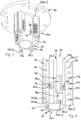
- the spindle 4 has two axial grooves 4.1 arranged in the longitudinal direction and opposite one another.
- the respective axial groove 4.1 extends to a shoulder or radially projecting edge 4.4, so that springs can be pushed into the grooves 4.1 up to the edge 4.4.
- the spindle 4 also has two recesses 4.2 which are placed at an axial distance from one another and which pierce an outer lateral surface 4.5.
- a cable, in particular a slip ring cable, can be passed through the recesses 4.2.
- a centering surface section 4.5a by means of which the spindle 4 can be centered in the cavity K, is provided above the edge 4.4.
Claims (16)
- Dispositif de montage (10) prévu au montage d'un dispositif de trépied (1) sous un plafond dans la salle d'opération, comportant- un organe de montage (30) s'étendant en direction longitudinale selon un axe de montage (D), conçu pour soutenir un élément de connexion (4) du dispositif de trépied, l'organe de montage (30) comportant au moins un tronçon de fixation (33) comprenant une pluralité de moyens de fixation (34) espacés longitudinalement l'un de l'autre, et- une bride de plafond (40) prévue au montage de l'organe de montage (30) sous un plafond et au stockage du dispositif de trépied au plafond, la bride de plafond (40) pouvant être montée en différentes positions de montage le long de l'axe de montage (D) relativement par rapport à l'organe de montage (30) de manière que le dispositif de montage (10) est apte à maintenir le dispositif de trépied (1) variablement en hauteur en différentes positions de hauteur notamment prédéfinies,caractérisé en ce quele dispositif de montage (10) comporte au moins deux attaches (50) permettant le couplage de l'organe de montage (30) à la bride de plafond (40) en différentes positions relatives, l'attache (50) comportant un tronçon de fixation (53, 56) configuré de façon géométriquement et correspondante par rapport au tronçon de fixation (33) de l'organe de montage (30), etla forme de l'organe de montage (30) est tubulaire, les tronçons de fixation (33) étant conçus sous forme d'ailettes s'étendant radialement depuis leur contour extérieur (31), deux tronçons de fixation (33) au moins étant prévus sur l'organe de montage (30), ceux-ci coopérant avec un nombre correspondant d'attaches (50) sur la bride de plafond (40).
- Dispositif de montage (10) selon la revendication 1, dans lequel les moyens de fixation (34) sont de configuration identique.
- Dispositif de montage (10) selon l'une des revendications précédentes, dans lequel les tronçons de fixation (33) s'étendent chacun selon la longueur totale de l'organe de montage (30).
- Dispositif de montage (10) selon l'une des revendications précédentes, dans lequel la bride de plafond (40) présente un passage (44) ayant de préférence un diamètre intérieur égal ou supérieur à un diamètre extérieur de l'organe de montage (30).
- Dispositif de montage (10) selon l'une des revendications précédentes, dans lequel la bride de plafond (40) présente une surface inférieure (42a.1) permettant le serrage de l'organe de montage (30) ou d'une attache (50), la bride de plafond (40) étant configurée de préférence comme plaque formant bride.
- Dispositif de montage (10) selon l'une des revendications précédentes, dans lequel la bride de plafond (40) comporte une pluralité de moyens de fixation (41), notamment des alésages à filetage femelle ou des trous traversants, conçus pour la fixation de l'organe de montage (30) à la bride de plafond (40) et s'étendant de préférence en direction longitudinale.
- Dispositif de montage (10) selon l'une des revendications précédentes, dans lequel l'attache (50) comporte au moins un moyen de fixation (56) disposé et / ou configuré de manière géométriquement correspondante à des moyens de fixation (34) de l'organe de montage (30).
- Dispositif de montage (10) selon l'une des revendications précédentes, dans lequel l'attache (50) présente une cavité (55), notamment une cavité radiale orientée dans le sens radial, dont la forme correspond géométriquement de telle manière au tronçon de fixation (33) de l'organe de montage (30) que l'attache (50) puisse enserrer le tronçon de fixation (33) dans le sens radial.
- Dispositif de montage (10) selon la revendication 1, dans lequel les au moins deux tronçons de fixation (33) s'étendent longitudinalement chacun selon la longueur totale de l'organe de montage (30), l'attache (50) comportant au moins un élément de fixation (56) disposé et / ou de manière géométriquement correspondante par rapport aux moyens de fixation (34) de l'organe de montage (30), la bride de plafond (40) ayant une surface inférieure (42a.1) permettant le serrage de l'attache (50), la bride de plafond (40) comportant une pluralité de moyens de fixation (41) orientés longitudinalement et permettant le montage de l'attache (50) sur la bride de plafond (40).
- Dispositif de montage (10) selon l'une des revendications précédentes, dans lequel au moins trois tronçons de fixation (33) sont prévus sur l'organe de montage (30) qui coopèrent avec un nombre correspondant d'attaches (50) sur la bride de plafond (40).
- Dispositif de montage (10) selon l'une des revendications précédentes, dans lequel l'élément de connexion (4) est une goupille.
- Système de montage comportant un dispositif de montage (10) selon l'une des revendications précédentes, dans lequel le système de montage comporte par ailleurs :- au moins un élément de fixation (90) servant au montage de la bride de plafond (40) sur l'organe de montage (30) ou sur une attache (50) reliée à l'organe de montage (30), et / ou- au moins un élément de fixation (80) prévu au montage d'au moins une attache (50) sur l'organe de montage (30).
- Système de montage selon la revendication 12, dans lequel le système de montage comporte par ailleurs :
un dispositif d'ajustage (20) pour placer un élément de connexion du dispositif de trépied (1) dans une position prédéfinissable par rapport à l'organe de montage (30), le dispositif de montage formant un accouplement rotatif ajustable autour de l'axe de montage pour le stockage de l'élément de connexion sur l'organe de montage. - Système de montage selon la revendication 12 ou 13, dans lequel le système de montage comporte par ailleurs :- un premier dispositif anti-rotation (60), notamment un boulon, et- un deuxième dispositif de blocage axial (70), notamment un verrou.
- Système de montage selon l'une des revendications 12 à 14, dans lequel, quant à l'élément de fixation (90) servant au montage de la bride de plafond (40) et / ou l'élément de fixation (80) servant au montage d'au moins une attache (50), il s'agit d'une vis.
- Dispositif de trépied (1), comportant :- un système de montage selon l'une des revendications 12 à 15, et- l'élément de connexion (4), l'élément de connexion étant de préférence une goupille montée ou fixée axialement fixe sur l'organe de montage (30) du dispositif de montage (10) du système de montage.
Applications Claiming Priority (2)
| Application Number | Priority Date | Filing Date | Title |
|---|---|---|---|
| EP14003555 | 2014-10-17 | ||
| PCT/EP2015/002061 WO2016058706A1 (fr) | 2014-10-17 | 2015-10-19 | Dispositif de montage d'un dispositif de support et système de montage pourvu du dispositif de montage |
Publications (2)
| Publication Number | Publication Date |
|---|---|
| EP3206652A1 EP3206652A1 (fr) | 2017-08-23 |
| EP3206652B1 true EP3206652B1 (fr) | 2023-02-15 |
Family
ID=51752973
Family Applications (1)
| Application Number | Title | Priority Date | Filing Date |
|---|---|---|---|
| EP15781871.7A Active EP3206652B1 (fr) | 2014-10-17 | 2015-10-19 | Dispositif de montage pour un dispositif à pied et système de montage doté d'un dispositif de montage |
Country Status (4)
| Country | Link |
|---|---|
| US (1) | US10780006B2 (fr) |
| EP (1) | EP3206652B1 (fr) |
| CN (1) | CN107072745B (fr) |
| WO (1) | WO2016058706A1 (fr) |
Families Citing this family (3)
| Publication number | Priority date | Publication date | Assignee | Title |
|---|---|---|---|---|
| NL2015811B1 (en) * | 2015-11-19 | 2017-06-06 | Vlaar Innovations B V | Monitor arm stand including a coupling piece, and coupling piece for such monitor arm stand. |
| US11123249B2 (en) * | 2018-05-02 | 2021-09-21 | Stryker Corporation | Vertically adjustable boom head and cable management therefor |
| CA3128340A1 (fr) * | 2019-01-31 | 2020-08-06 | American Sterilizer Company | Adaptateurs modulaires pour systeme de support de dispositif medical |
Family Cites Families (56)
| Publication number | Priority date | Publication date | Assignee | Title |
|---|---|---|---|---|
| US1517626A (en) * | 1921-03-05 | 1924-12-02 | Herskovitz William | Electric-lighting fixture |
| US2147284A (en) * | 1937-05-01 | 1939-02-14 | Miller Co | Hickey |
| US2692745A (en) * | 1951-06-07 | 1954-10-26 | Donald B Alexander | Antenna mast clamp |
| US2795859A (en) | 1955-01-24 | 1957-06-18 | Buschbach Jake | Apparatus for testing the accuracy of wheel alignment measuring equipment |
| US2916249A (en) * | 1955-02-09 | 1959-12-08 | Wolar Isidore | Lighting fixture hanger |
| US2956573A (en) * | 1959-06-01 | 1960-10-18 | Brown Rutherford | Automobile windshield cover |
| US3814023A (en) * | 1973-06-19 | 1974-06-04 | New Standard Co Inc | Vertically adjustable suspension assembly |
| DE3100819A1 (de) | 1981-01-14 | 1982-07-29 | Drägerwerk AG, 2400 Lübeck | Deckendrehlager fuer die halterung von in ihrer lage feststellbaren medizinischen geraeten und der anschluesse von energie- und gasversorgungsleitungen im klinischen bereich |
| US4673154A (en) * | 1983-07-05 | 1987-06-16 | Karapita Alexander D | Suspension device |
| US4738369A (en) * | 1983-08-05 | 1988-04-19 | Desjardins Wallace H | Ceiling support for patient monitoring equipment |
| US4687167A (en) | 1985-10-23 | 1987-08-18 | Skalka Gerald P | Multi-position computer support |
| US4684097A (en) * | 1986-04-14 | 1987-08-04 | Cox Roger W | Mobile home stanchions |
| US4901967A (en) * | 1986-07-15 | 1990-02-20 | The Cleveland Clinic Foundation | Patient equipment transport and support system |
| US4803819A (en) * | 1986-11-03 | 1989-02-14 | Frank Kelsey | Utility pole and attachments formed by pultrusion of dielectric insulating plastic, such as glass fiber reinforced resin |
| DE3805422C1 (fr) * | 1988-02-22 | 1988-12-15 | Rittal-Werk Rudolf Loh Gmbh & Co Kg, 6348 Herborn, De | |
| US4840278A (en) * | 1988-05-17 | 1989-06-20 | Yvon Gelinas | Ceiling rack |
| US4948083A (en) | 1989-04-17 | 1990-08-14 | Penn Fishing And Tackle Mfg. Co. | Swivel base mount for downrigger |
| US5014693A (en) * | 1989-10-25 | 1991-05-14 | St. Luke's Episcopal Hospital | Ceiling-mounted gas delivering unit for use in a catheter laboratory |
| FR2662779B3 (fr) * | 1990-05-31 | 1992-05-07 | Lefebvre Alain | Suspension plafonniere pour la fixation d'un televiseur ou tout autre appareil de forme similaire. |
| DE9204321U1 (fr) * | 1992-03-31 | 1992-05-21 | Trilux-Lenze Gmbh + Co Kg, 5760 Arnsberg, De | |
| DE4317923A1 (de) | 1993-05-28 | 1994-12-01 | Kreuzer Gmbh & Co Ohg | Zwischengestell für die Befestigung eines Deckenstatives |
| US5505420A (en) * | 1994-09-22 | 1996-04-09 | Brown; Joe K. | Ceiling fan stabilizer |
| DE29805542U1 (de) * | 1998-03-26 | 1998-06-04 | Walter Haenel Gmbh F | Gelenkkörper, insbesondere zur schwenkbaren Befestigung eines Monitors |
| US6443596B1 (en) | 1998-03-27 | 2002-09-03 | Hill-Rom Services, Inc. | Surgical light apparatus with improved cooling |
| US6095468A (en) | 1998-03-27 | 2000-08-01 | Hill-Rom, Inc. | Support arm for a service column |
| US6639623B2 (en) | 1999-12-23 | 2003-10-28 | Hill-Rom Services, Inc. | Controls for a surgical theater system |
| DE10025839C1 (de) | 2000-05-25 | 2002-01-17 | Mavig Gmbh | Ausleger |
| US6443406B1 (en) * | 2001-02-16 | 2002-09-03 | Kompan A/S | Means of mounting and adjusting telescopic metal tubes |
| US7823347B1 (en) * | 2001-02-27 | 2010-11-02 | Lawrence Blinn | Structural member and structural systems using structural member |
| CN2499016Y (zh) * | 2001-08-02 | 2002-07-10 | 东莞羚亚医护用品制造厂有限公司 | 医用吊塔 |
| US7097145B2 (en) | 2001-09-14 | 2006-08-29 | Hill-Rom Services, Inc. | Support arm for a surgical theater system |
| US6647820B2 (en) | 2001-09-17 | 2003-11-18 | Lockheed Martin Corporation | Variable position hand control mount for operator controls |
| ES2242893T3 (es) * | 2001-11-05 | 2005-11-16 | Steris Inc. | Sistema medico de suspension con dos arboles giratorios. |
| US7770860B1 (en) | 2005-11-10 | 2010-08-10 | Modular Services Company | Medical service system on articulating arm with electromagnetic brakes |
| US20080116333A1 (en) * | 2006-11-20 | 2008-05-22 | Hung-Yueh Chang | Supporting rod assembly structure |
| ES2341580T3 (es) | 2007-11-15 | 2010-06-22 | Ingolf Diez, Medizintechnik | Dispositivo de soporte de aparatos medicos. |
| DE102008011129A1 (de) | 2008-02-26 | 2009-08-27 | Berchtold Holding Gmbh | Aufhängung |
| US8197154B2 (en) | 2008-10-31 | 2012-06-12 | Midmark Corporation | Articulating joint for dental or medical lights |
| EP2325541B1 (fr) | 2009-11-18 | 2013-05-22 | Ondal Medical Systems GmbH | Mécanisme d'arrêt ajustable pour connexion rotative |
| CN201723623U (zh) * | 2010-07-09 | 2011-01-26 | 浏阳太阳龙医疗科技有限公司 | 一种医用吊塔关节电磁制动装置 |
| CN201734892U (zh) * | 2010-07-28 | 2011-02-09 | 美迪兰(南京)医疗设备有限公司 | 弹簧臂的二次保护装置 |
| US8276867B2 (en) | 2010-08-12 | 2012-10-02 | Modernsolid Industrial Co., Ltd. | Adjustable projector bracket assembly |
| DE102010051633A1 (de) * | 2010-11-17 | 2012-05-24 | Ondal Medical Systems Gmbh | Tragesystem mit Bedienungshilfe |
| CN102553087B (zh) * | 2010-12-30 | 2016-04-20 | 苏州雷泰医疗科技有限公司 | 一种病床自动定位装置 |
| CN201977934U (zh) * | 2011-01-30 | 2011-09-21 | 北京谊安医疗系统股份有限公司 | 吊塔装置 |
| US8960624B2 (en) | 2011-04-01 | 2015-02-24 | Allied Tube & Conduit Corporation | Medical device mounting system |
| CN102900922A (zh) | 2011-07-27 | 2013-01-30 | 鸿富锦精密工业(深圳)有限公司 | 显示器支撑装置 |
| US9033106B2 (en) * | 2012-01-04 | 2015-05-19 | Lawrence Blinn | Safety barrier netting system |
| US9528285B2 (en) * | 2012-01-04 | 2016-12-27 | Lawrence Blinn | Safety barrier netting system with rigid panel net supports and stopper mechanisms |
| US8763267B2 (en) | 2012-01-20 | 2014-07-01 | Hexagon Technology Center Gmbh | Locking counterbalance for a CMM |
| DE102012001197A1 (de) | 2012-01-24 | 2013-07-25 | Provita Medical Gmbh | Stativ, insbesondere für einen Infusionsständer oder als Halterung für medizinische Geräte |
| WO2014072964A1 (fr) | 2012-11-12 | 2014-05-15 | Oasys Healthcare Corporation | Câblage pour système suspendu à axe central |
| DE102012112712A1 (de) * | 2012-12-20 | 2014-06-26 | MAQUET GmbH | Instrumentenhalter |
| JP6327640B2 (ja) | 2014-04-30 | 2018-05-23 | ミネベアミツミ株式会社 | 回転範囲制限装置及び構造体を含む装置 |
| CN103953837B (zh) * | 2014-05-06 | 2016-05-11 | 迈柯唯医疗设备(苏州)有限公司 | 医用吊塔臂系统及用于该医用吊塔臂系统的转轴 |
| EP3593780A3 (fr) | 2014-10-17 | 2020-04-15 | Ondal Medical Systems GmbH | Dispositif de montage à accouplement rotatif pour un dispositif de trépied |
-
2015
- 2015-10-19 US US15/517,898 patent/US10780006B2/en active Active
- 2015-10-19 CN CN201580056028.XA patent/CN107072745B/zh active Active
- 2015-10-19 EP EP15781871.7A patent/EP3206652B1/fr active Active
- 2015-10-19 WO PCT/EP2015/002061 patent/WO2016058706A1/fr active Application Filing
Also Published As
| Publication number | Publication date |
|---|---|
| US10780006B2 (en) | 2020-09-22 |
| EP3206652A1 (fr) | 2017-08-23 |
| CN107072745B (zh) | 2021-02-26 |
| CN107072745A (zh) | 2017-08-18 |
| US20180228680A1 (en) | 2018-08-16 |
| WO2016058706A1 (fr) | 2016-04-21 |
Similar Documents
| Publication | Publication Date | Title |
|---|---|---|
| EP3206653B1 (fr) | Dispositif de montage avec accouplement rotatif pour un dispositif à pied | |
| EP2937619B1 (fr) | Liaison rotative doté d'une limitation d'angle de rotation | |
| EP2937617B1 (fr) | Liaison rotative doté d'une limitation d'angle de rotation | |
| EP2937618B1 (fr) | Liaison rotative dotée d'une limitation d'angle de rotation | |
| EP3217939B1 (fr) | Articulation d'appui pour un arbre de support d'un dispositif à pied médical | |
| EP3174488B1 (fr) | Douille, bras de support et système de support pour un socle médical | |
| EP2846049B1 (fr) | Système de fixation avec système excentrique | |
| EP3206652B1 (fr) | Dispositif de montage pour un dispositif à pied et système de montage doté d'un dispositif de montage | |
| EP2925487B1 (fr) | Dispositif de retenue de pièce et procédé pour munir un dispositif de retenue de pièce d'une pièce | |
| EP3207300B1 (fr) | Élément de sécurisation pour dispositif à pied et composants correspondants | |
| WO2016015870A1 (fr) | Câblage insensible aux mouvements pour un dispositif sur pied | |
| EP2940367A1 (fr) | Liaison rotative dotée d'une limitation d'angle de rotation | |
| EP2778492A1 (fr) | Liaison de deux pièces d'adaptation d'un dispositif de support modulaire | |
| EP0962280B1 (fr) | Dispositif d'alignement | |
| WO2017216306A1 (fr) | Transmission à train épicycloïdal | |
| DE102014211272B4 (de) | Wellenkupplung | |
| WO2011120651A1 (fr) | Fixation d'un mât pour lampadaire | |
| EP3064857B1 (fr) | Capot d'appareil | |
| EP3120821B1 (fr) | Dispositif de retenue et de positionnement médical | |
| CH693060A5 (de) | Feststellvorrichtung. | |
| DE2630404B2 (de) | Strebe zur Arretierung eines mechanischen Elementes | |
| WO2006102908A1 (fr) | Dispositif pour recevoir, orienter et ajuster un element optique | |
| DE102013205693A1 (de) | Zwischenverbinder | |
| WO2012168308A1 (fr) | Support variable et procédé de montage |
Legal Events
| Date | Code | Title | Description |
|---|---|---|---|
| STAA | Information on the status of an ep patent application or granted ep patent |
Free format text: STATUS: THE INTERNATIONAL PUBLICATION HAS BEEN MADE |
|
| PUAI | Public reference made under article 153(3) epc to a published international application that has entered the european phase |
Free format text: ORIGINAL CODE: 0009012 |
|
| STAA | Information on the status of an ep patent application or granted ep patent |
Free format text: STATUS: REQUEST FOR EXAMINATION WAS MADE |
|
| 17P | Request for examination filed |
Effective date: 20170410 |
|
| AK | Designated contracting states |
Kind code of ref document: A1 Designated state(s): AL AT BE BG CH CY CZ DE DK EE ES FI FR GB GR HR HU IE IS IT LI LT LU LV MC MK MT NL NO PL PT RO RS SE SI SK SM TR |
|
| AX | Request for extension of the european patent |
Extension state: BA ME |
|
| DAV | Request for validation of the european patent (deleted) | ||
| DAX | Request for extension of the european patent (deleted) | ||
| STAA | Information on the status of an ep patent application or granted ep patent |
Free format text: STATUS: EXAMINATION IS IN PROGRESS |
|
| 17Q | First examination report despatched |
Effective date: 20181120 |
|
| STAA | Information on the status of an ep patent application or granted ep patent |
Free format text: STATUS: EXAMINATION IS IN PROGRESS |
|
| GRAP | Despatch of communication of intention to grant a patent |
Free format text: ORIGINAL CODE: EPIDOSNIGR1 |
|
| STAA | Information on the status of an ep patent application or granted ep patent |
Free format text: STATUS: GRANT OF PATENT IS INTENDED |
|
| INTG | Intention to grant announced |
Effective date: 20220628 |
|
| GRAJ | Information related to disapproval of communication of intention to grant by the applicant or resumption of examination proceedings by the epo deleted |
Free format text: ORIGINAL CODE: EPIDOSDIGR1 |
|
| STAA | Information on the status of an ep patent application or granted ep patent |
Free format text: STATUS: EXAMINATION IS IN PROGRESS |
|
| GRAP | Despatch of communication of intention to grant a patent |
Free format text: ORIGINAL CODE: EPIDOSNIGR1 |
|
| STAA | Information on the status of an ep patent application or granted ep patent |
Free format text: STATUS: GRANT OF PATENT IS INTENDED |
|
| INTC | Intention to grant announced (deleted) | ||
| GRAS | Grant fee paid |
Free format text: ORIGINAL CODE: EPIDOSNIGR3 |
|
| INTG | Intention to grant announced |
Effective date: 20221129 |
|
| GRAA | (expected) grant |
Free format text: ORIGINAL CODE: 0009210 |
|
| STAA | Information on the status of an ep patent application or granted ep patent |
Free format text: STATUS: THE PATENT HAS BEEN GRANTED |
|
| AK | Designated contracting states |
Kind code of ref document: B1 Designated state(s): AL AT BE BG CH CY CZ DE DK EE ES FI FR GB GR HR HU IE IS IT LI LT LU LV MC MK MT NL NO PL PT RO RS SE SI SK SM TR |
|
| REG | Reference to a national code |
Ref country code: CH Ref legal event code: EP Ref country code: GB Ref legal event code: FG4D Free format text: NOT ENGLISH |
|
| REG | Reference to a national code |
Ref country code: DE Ref legal event code: R096 Ref document number: 502015016267 Country of ref document: DE |
|
| REG | Reference to a national code |
Ref country code: AT Ref legal event code: REF Ref document number: 1547882 Country of ref document: AT Kind code of ref document: T Effective date: 20230315 Ref country code: IE Ref legal event code: FG4D Free format text: LANGUAGE OF EP DOCUMENT: GERMAN |
|
| REG | Reference to a national code |
Ref country code: NL Ref legal event code: FP |
|
| REG | Reference to a national code |
Ref country code: LT Ref legal event code: MG9D |
|
| P01 | Opt-out of the competence of the unified patent court (upc) registered |
Effective date: 20230526 |
|
| PG25 | Lapsed in a contracting state [announced via postgrant information from national office to epo] |
Ref country code: RS Free format text: LAPSE BECAUSE OF FAILURE TO SUBMIT A TRANSLATION OF THE DESCRIPTION OR TO PAY THE FEE WITHIN THE PRESCRIBED TIME-LIMIT Effective date: 20230215 Ref country code: PT Free format text: LAPSE BECAUSE OF FAILURE TO SUBMIT A TRANSLATION OF THE DESCRIPTION OR TO PAY THE FEE WITHIN THE PRESCRIBED TIME-LIMIT Effective date: 20230615 Ref country code: NO Free format text: LAPSE BECAUSE OF FAILURE TO SUBMIT A TRANSLATION OF THE DESCRIPTION OR TO PAY THE FEE WITHIN THE PRESCRIBED TIME-LIMIT Effective date: 20230515 Ref country code: LV Free format text: LAPSE BECAUSE OF FAILURE TO SUBMIT A TRANSLATION OF THE DESCRIPTION OR TO PAY THE FEE WITHIN THE PRESCRIBED TIME-LIMIT Effective date: 20230215 Ref country code: LT Free format text: LAPSE BECAUSE OF FAILURE TO SUBMIT A TRANSLATION OF THE DESCRIPTION OR TO PAY THE FEE WITHIN THE PRESCRIBED TIME-LIMIT Effective date: 20230215 Ref country code: HR Free format text: LAPSE BECAUSE OF FAILURE TO SUBMIT A TRANSLATION OF THE DESCRIPTION OR TO PAY THE FEE WITHIN THE PRESCRIBED TIME-LIMIT Effective date: 20230215 Ref country code: ES Free format text: LAPSE BECAUSE OF FAILURE TO SUBMIT A TRANSLATION OF THE DESCRIPTION OR TO PAY THE FEE WITHIN THE PRESCRIBED TIME-LIMIT Effective date: 20230215 |
|
| PG25 | Lapsed in a contracting state [announced via postgrant information from national office to epo] |
Ref country code: SE Free format text: LAPSE BECAUSE OF FAILURE TO SUBMIT A TRANSLATION OF THE DESCRIPTION OR TO PAY THE FEE WITHIN THE PRESCRIBED TIME-LIMIT Effective date: 20230215 Ref country code: PL Free format text: LAPSE BECAUSE OF FAILURE TO SUBMIT A TRANSLATION OF THE DESCRIPTION OR TO PAY THE FEE WITHIN THE PRESCRIBED TIME-LIMIT Effective date: 20230215 Ref country code: IS Free format text: LAPSE BECAUSE OF FAILURE TO SUBMIT A TRANSLATION OF THE DESCRIPTION OR TO PAY THE FEE WITHIN THE PRESCRIBED TIME-LIMIT Effective date: 20230615 Ref country code: GR Free format text: LAPSE BECAUSE OF FAILURE TO SUBMIT A TRANSLATION OF THE DESCRIPTION OR TO PAY THE FEE WITHIN THE PRESCRIBED TIME-LIMIT Effective date: 20230516 Ref country code: FI Free format text: LAPSE BECAUSE OF FAILURE TO SUBMIT A TRANSLATION OF THE DESCRIPTION OR TO PAY THE FEE WITHIN THE PRESCRIBED TIME-LIMIT Effective date: 20230215 |
|
| PG25 | Lapsed in a contracting state [announced via postgrant information from national office to epo] |
Ref country code: SM Free format text: LAPSE BECAUSE OF FAILURE TO SUBMIT A TRANSLATION OF THE DESCRIPTION OR TO PAY THE FEE WITHIN THE PRESCRIBED TIME-LIMIT Effective date: 20230215 Ref country code: RO Free format text: LAPSE BECAUSE OF FAILURE TO SUBMIT A TRANSLATION OF THE DESCRIPTION OR TO PAY THE FEE WITHIN THE PRESCRIBED TIME-LIMIT Effective date: 20230215 Ref country code: EE Free format text: LAPSE BECAUSE OF FAILURE TO SUBMIT A TRANSLATION OF THE DESCRIPTION OR TO PAY THE FEE WITHIN THE PRESCRIBED TIME-LIMIT Effective date: 20230215 Ref country code: DK Free format text: LAPSE BECAUSE OF FAILURE TO SUBMIT A TRANSLATION OF THE DESCRIPTION OR TO PAY THE FEE WITHIN THE PRESCRIBED TIME-LIMIT Effective date: 20230215 |
|
| REG | Reference to a national code |
Ref country code: DE Ref legal event code: R097 Ref document number: 502015016267 Country of ref document: DE |
|
| PG25 | Lapsed in a contracting state [announced via postgrant information from national office to epo] |
Ref country code: SK Free format text: LAPSE BECAUSE OF FAILURE TO SUBMIT A TRANSLATION OF THE DESCRIPTION OR TO PAY THE FEE WITHIN THE PRESCRIBED TIME-LIMIT Effective date: 20230215 |
|
| PLBE | No opposition filed within time limit |
Free format text: ORIGINAL CODE: 0009261 |
|
| STAA | Information on the status of an ep patent application or granted ep patent |
Free format text: STATUS: NO OPPOSITION FILED WITHIN TIME LIMIT |
|
| 26N | No opposition filed |
Effective date: 20231116 |
|
| PG25 | Lapsed in a contracting state [announced via postgrant information from national office to epo] |
Ref country code: SI Free format text: LAPSE BECAUSE OF FAILURE TO SUBMIT A TRANSLATION OF THE DESCRIPTION OR TO PAY THE FEE WITHIN THE PRESCRIBED TIME-LIMIT Effective date: 20230215 |