EP2325541B1 - Mécanisme d'arrêt ajustable pour connexion rotative - Google Patents
Mécanisme d'arrêt ajustable pour connexion rotative Download PDFInfo
- Publication number
- EP2325541B1 EP2325541B1 EP09014411.4A EP09014411A EP2325541B1 EP 2325541 B1 EP2325541 B1 EP 2325541B1 EP 09014411 A EP09014411 A EP 09014411A EP 2325541 B1 EP2325541 B1 EP 2325541B1
- Authority
- EP
- European Patent Office
- Prior art keywords
- joint member
- joint
- stop
- relative
- rotation
- Prior art date
- Legal status (The legal status is an assumption and is not a legal conclusion. Google has not performed a legal analysis and makes no representation as to the accuracy of the status listed.)
- Active
Links
- 230000000295 complement effect Effects 0.000 claims description 2
- 230000004048 modification Effects 0.000 description 2
- 238000012986 modification Methods 0.000 description 2
- 230000006978 adaptation Effects 0.000 description 1
- 238000007792 addition Methods 0.000 description 1
- 238000009434 installation Methods 0.000 description 1
- 230000003068 static effect Effects 0.000 description 1
Images

Classifications
-
- F—MECHANICAL ENGINEERING; LIGHTING; HEATING; WEAPONS; BLASTING
- F16—ENGINEERING ELEMENTS AND UNITS; GENERAL MEASURES FOR PRODUCING AND MAINTAINING EFFECTIVE FUNCTIONING OF MACHINES OR INSTALLATIONS; THERMAL INSULATION IN GENERAL
- F16M—FRAMES, CASINGS OR BEDS OF ENGINES, MACHINES OR APPARATUS, NOT SPECIFIC TO ENGINES, MACHINES OR APPARATUS PROVIDED FOR ELSEWHERE; STANDS; SUPPORTS
- F16M11/00—Stands or trestles as supports for apparatus or articles placed thereon Stands for scientific apparatus such as gravitational force meters
- F16M11/02—Heads
- F16M11/04—Means for attachment of apparatus; Means allowing adjustment of the apparatus relatively to the stand
- F16M11/06—Means for attachment of apparatus; Means allowing adjustment of the apparatus relatively to the stand allowing pivoting
-
- F—MECHANICAL ENGINEERING; LIGHTING; HEATING; WEAPONS; BLASTING
- F16—ENGINEERING ELEMENTS AND UNITS; GENERAL MEASURES FOR PRODUCING AND MAINTAINING EFFECTIVE FUNCTIONING OF MACHINES OR INSTALLATIONS; THERMAL INSULATION IN GENERAL
- F16C—SHAFTS; FLEXIBLE SHAFTS; ELEMENTS OR CRANKSHAFT MECHANISMS; ROTARY BODIES OTHER THAN GEARING ELEMENTS; BEARINGS
- F16C11/00—Pivots; Pivotal connections
- F16C11/04—Pivotal connections
- F16C11/10—Arrangements for locking
-
- F—MECHANICAL ENGINEERING; LIGHTING; HEATING; WEAPONS; BLASTING
- F16—ENGINEERING ELEMENTS AND UNITS; GENERAL MEASURES FOR PRODUCING AND MAINTAINING EFFECTIVE FUNCTIONING OF MACHINES OR INSTALLATIONS; THERMAL INSULATION IN GENERAL
- F16C—SHAFTS; FLEXIBLE SHAFTS; ELEMENTS OR CRANKSHAFT MECHANISMS; ROTARY BODIES OTHER THAN GEARING ELEMENTS; BEARINGS
- F16C2316/00—Apparatus in health or amusement
- F16C2316/10—Apparatus in health or amusement in medical appliances, e.g. in diagnosis, dentistry, instruments, prostheses, medical imaging appliances
-
- F—MECHANICAL ENGINEERING; LIGHTING; HEATING; WEAPONS; BLASTING
- F16—ENGINEERING ELEMENTS AND UNITS; GENERAL MEASURES FOR PRODUCING AND MAINTAINING EFFECTIVE FUNCTIONING OF MACHINES OR INSTALLATIONS; THERMAL INSULATION IN GENERAL
- F16M—FRAMES, CASINGS OR BEDS OF ENGINES, MACHINES OR APPARATUS, NOT SPECIFIC TO ENGINES, MACHINES OR APPARATUS PROVIDED FOR ELSEWHERE; STANDS; SUPPORTS
- F16M2200/00—Details of stands or supports
- F16M2200/02—Locking means
- F16M2200/021—Locking means for rotational movement
- F16M2200/024—Locking means for rotational movement by positive interaction, e.g. male-female connections
-
- Y—GENERAL TAGGING OF NEW TECHNOLOGICAL DEVELOPMENTS; GENERAL TAGGING OF CROSS-SECTIONAL TECHNOLOGIES SPANNING OVER SEVERAL SECTIONS OF THE IPC; TECHNICAL SUBJECTS COVERED BY FORMER USPC CROSS-REFERENCE ART COLLECTIONS [XRACs] AND DIGESTS
- Y10—TECHNICAL SUBJECTS COVERED BY FORMER USPC
- Y10T—TECHNICAL SUBJECTS COVERED BY FORMER US CLASSIFICATION
- Y10T403/00—Joints and connections
- Y10T403/32—Articulated members
- Y10T403/32975—Rotatable
Definitions
- the present invention relates to an adjustable stop mechanism for a rotatable connection or a pivot connection. More particularly, the adjustable stop mechanism is preferably designed for use in a swivel or pivot joint of a mounting arm, such as the type used for supporting technical equipment, e.g. in hospitals and in industrial environments. Thus, the present invention also relates to a swivel or pivot joint, such as a pivot joint of a mounting arm, incorporating such a stop mechanism.
- the limits or end-points of the rotation or pivot in the connection or joint can be adjusted and/or set to provide a consistent and reliable definition of the range of rotational movement available in the mounting arm.
- the swivel or pivot joint of the mounting arm can be variably adjusted or set to suit the specific requirements of the room or space in which the technical equipment is to be installed, and/or to suit the requirements of the equipment itself mounted on the arm. It will be convenient to hereafter describe the invention in this particular context. It is to be noted, however, that the adjustable stop mechanism of the invention is not limited to use in a swivel or pivotable joint of a mounting arm.
- the provision of one or more stops in a rotatable connection or a pivot connection for limiting or defining a range of rotational movement available in a support arm or mounting arm or other structure is known in the art. Conventionally, however, such stops are fixed and do not enable the user to adjust or modify the range of movement depending upon the particular spatial parameters available for the installation of the rotatable connection and/or depending upon the technical field of application.
- the present invention is directed to the problem of providing a new and improved stop mechanism for a rotatable joint, with which a user may readily adjust and/or set a range of rotational movement in the joint.
- Such conventional rotatable joints are known from DE 3808327 A1 and US 1634922 A1 .
- the present invention provides an adjustable stop mechanism for a rotatable connection or joint, such as a pivot joint or a swivel joint, where the joint comprises a first joint member and a second joint member, the second joint member being connected with the first joint member and rotatable relative thereto about an axis.
- the stop mechanism comprises: a first part to be provided on the first joint member and having at least a first stop which defines at least a first limit of relative rotation of the second joint member.
- the first part of the stop mechanism is adapted to be selectively positioned with respect to the first joint member to set or to define a range of rotation of the second joint member relative to the first joint member, wherein the first part of the adjustable stop mechanism is adapted to be selectively positioned around a circumferential of the first joint member, the first part of the stop mechanism is ring-shaped such that it extends around a shaft or column of the first joint member.
- the first joint member is configured as a shaft or column around which the second joint member is configured to rotate or pivot.
- the second joint member preferably comprises a sleeve or collar component which extends around the first joint member.
- the stop mechanism of the invention is preferably arranged between the first joint member and the second joint member, and more particularly, is preferably located between the shaft or column of the first joint member and the sleeve or collar of the second joint member.
- the adjustable stop mechanism further comprises a second part to be provided on the first joint member having a second stop defining a second limit of relative rotation of the second joint member.
- the first and second parts of the stop mechanism are adapted to be selectively positioned with respect to the first joint member to define a range of rotation of the second joint member relative to the first joint member between the first stop and the second stop.
- the first stop comprises an abutment member which is configured to be located in a path of the second joint member to block or prevent rotation of the second joint member relative to the first joint member.
- the second stop preferably comprises an abutment member which is configured to be located in the path of the second joint member to block or prevent rotation of the second joint member relative to the first joint member.
- the first part of the adjustable stop mechanism is configured to be selectively positioned to locate the first stop with respect to the first joint member.
- a user can position the first stop at a desired location with respect to the first joint member in order to define or set at least a first limit of rotation of the second joint member, i.e. at an end of the path of rotation.
- the first part of the stop mechanism may be adapted to be selectively positioned around a circumference of the first joint member.
- the first part of the stop mechanism preferably includes means for registered interconnection with the first joint member to fix the first stop against rotation about said axis relative to the first joint member at different positions.
- the means for registered interconnection may, for example, comprise a first detent mechanism with one or more recesses or projections formed in or on the first part of the stop mechanism for corresponding receipt of, or engagement with, one or more complementary projections or recesses formed on or in the first joint member.
- a plurality of such recesses or projections are provided spaced apart from one another at intervals, e.g. regular intervals, around a circumference or periphery of the first part of the stop mechanism and/or of the first joint member.
- the first part of the stop mechanism is ring-shaped or formed as a sleeve to be mounted on the first joint member.
- the stop mechanism includes only a single stop (e.g. only a first stop on the first part), that stop may nevertheless define or provide two limits to the relative rotation of the second joint member at opposite ends of the path of rotation. That is, the abutment member of the first stop may present opposite abutment surfaces, which each abutment surface forming a respective end of the rotation path. It is also conceivable that two stops could be provided on the first part for defining the range of the relative rotation of the second joint member there-between. As noted above, however, in preferred embodiments the stop mechanism of the invention includes a second part having a second stop, and defines a range of rotation of the second joint member relative to the first joint member between the first stop and the second stop.
- the second part of the stop mechanism is configured to be selectively positioned to locate the second stop with respect to the first stop.
- the first and second parts of the stop mechanism are thus configured to be independently positioned with respect to the first joint member.
- the second part is preferably designed to be provided on the first part, and may therefore be selectively positioned with respect to the first part.
- a user can begin by positioning the first stop at a desired location with respect to the first joint member in order to define or set the first limit of rotation of the second joint member (i.e. at one end of the path of rotation).
- the user can then position the second stop to set or define the second limit of rotation of the second joint member (i.e. at the other end of the path of rotation).
- This provides the user with the flexibility to adjust and to adapt the stop mechanism to suit the environment in which the rotatable joint, e.g. pivot joint or swivel joint, is employed.
- the second part of the stop mechanism is adapted to be selectively positioned around a circumference of the first joint member.
- the stop mechanism includes means for registered positioning of the second part on the first part to fix the second stop against rotation about said axis relative to the first part at any of a plurality of positions.
- the means for registered positioning of the second part thus preferably comprises a second detent mechanism with a plurality of recesses or projections formed in the first part for corresponding receipt of, or engagement with, a registration member of the second part.
- the present invention provides a rotatable joint, such as a pivot joint or a swivel joint for a mounting arm, which incorporates the adjustable stop mechanism of the invention.
- the joint comprises: a first joint member for connection to a reference frame; a second joint member connected with the first joint member and configured for rotation relative to the first joint member about a rotational axis; and an adjustable stop mechanism for defining the limits of rotation of the second joint member relative to the first joint member.
- the reference frame to which the first joint member is connected will typically be a stationary reference frame, such as a wall or ceiling of a building. It will be noted, however, that the present invention applies equally to a situation where the reference frame is non-stationary or mobile, as may be the case where the joint is incorporated in an articulated mechanism, on a piece of machinery, or in a vehicle.
- the first joint member may be configured as a shaft or column and the second joint member may be configured as a sleeve or collar component that extends around and pivots about the first joint member.
- the adjustable stop mechanism comprises: a first part which is provided on the first joint member and has a first stop defining at least a first limit of rotation of the second joint member relative to the first joint member.
- the first part is adapted to be selectively and independently positioned with respect to the first joint member to set a range of rotation of the second joint member relative to the first joint member.
- the stop mechanism of the invention is preferably arranged between the first joint member and the second joint member, e.g. between the shaft or column of the first joint member and the sleeve or collar of the second joint member.
- the stop mechanism further comprises a second part which is provided on the first joint member and has a second stop for defining a second limit of rotation of the second joint member relative to the first joint member.
- the first part and the second part are adapted to be selectively and independently positioned with respect to the first joint member to set or to define a range of rotation of the second joint member relative to the first joint member between the first stop and the second stop.
- the second joint member comprises an engagement member, which travels a path between the stops during rotation of the second joint member relative to the first joint member and which engages or comes into abutment with a respective one of the stops at each limit of the relative rotation.
- the second joint member is connected substantially coaxially with the first joint member, and the engagement member projects radially from the second joint member, preferably radially inwardly, to engage or come into abutment with each of the first and second stops at the limits of its rotation relative to the first joint member.
- the present invention provides a mounting arm for supporting technical equipment, such as in a hospital or in a commercial or in an industrial environment.
- the mounting arm of the invention incorporates a rotatable joint according to the invention, as described above.
- a mounting arm A with a rotatable connection 1 is illustrated in a sectioned side view.
- the mounting arm A includes a support member S (partly shown in Fig. 1 ) which extends horizontally from the rotatable connection 1 to a distal end (not shown) designed to support technical equipment, such as lighting, one or more computer display screen, and/or any of a variety of medical or industrial equipment for use in a corresponding environment (e.g. hospital, medical practice, factory etc.).
- the rotatable connection 1 is in the form of a pivot joint or swivel joint in the mounting arm A.
- the rotatable joint 1 comprises a first joint member 10 in the form of a substantially vertically extending cylindrical shaft or column 11, which is designed to be rigidly secured to a structure, such as a ceiling of a building, via mounting flanges 12. The ceiling of the building thus forms a static reference frame for the joint 1.
- the rotatable joint 1 comprises a second joint member 20 in the form of a generally cylindrical sleeve 21 which is mounted on a lower end of the first joint member 10 and extends around the shaft 11.
- the second joint member 20 is connected to the first joint member 10 for rotation relative to the first joint member about a central axis 13 of the shaft 11. That is, as can be seen in Fig. 1 , the sleeve 21 is mounted on upper and lower bearings 14, 15 (e.g. roller bearings) for rotary movement relative to the shaft 11 about the central axis 13.
- upper and lower bearings 14, 15 e.g. roller bearings
- the limits and/or the range of rotational movement of the sleeve 21 (and, thus, of the support member S which is rigidly connected to the sleeve 21) relative to the shaft 11 is able to be adjusted and set with an adjustable stop mechanism 30 located between the first and second joint members 10, 20.
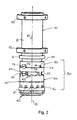
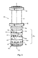
- an adjustable stop mechanism 30 located between the first and second joint members 10, 20. Details of the stop mechanism 30 will be more apparent from Figs. 2 and 3 of the drawings, in which the pivot joint 1 is illustrated in perspective side views without the sleeve 21 of the second joint member 20. In other words, the parts of the adjustable stop mechanism 30 are clearly visible mounted around the cylindrical shaft 11 when the sleeve 21 of the second joint member 20 is removed.
- the stop mechanism 30 comprises a first part 40 in the form of a generally ring-shaped first collar which extends around the outer periphery of the shaft 11 of the first joint member 10.
- the inner diameter of the first part or first collar 40 is slightly larger than the outer diameter of the shaft 11 to provide a small amount of play that enables the collar 40 to be moved freely or independently relative to the shaft 11.
- the collar 40 includes a first stop 41 in the form of a rectangular abutment member which is integral with and extends upwardly from an upper edge region of the first collar 40. As will be described in more detail later, the first stop 41 is designed to block or prevent rotation of the second joint member 20 relative to the first joint member 10.
- the stop mechanism 30 also comprises a second part 50 in the form of another generally ring-shaped collar which also extends around the outer periphery of the shaft 11 above the first collar 40.
- the inner diameter of the second part or second collar 50 is slightly larger than the outer diameter of shaft 11 so that this collar 50 is freely movable relative to the shaft.
- the second collar 50 includes a second stop 51 in the form of a rectangular abutment member which is integral with and extends downwardly from a lower edge region of that second collar 50 towards the first collar 40. This second stop 51 is also designed to block or prevent rotation of the second joint member 20 relative to the first joint member 10.
- the first collar 40 of the stop mechanism 30 in this embodiment sits or rests against an upper surface of the lower bearing 15 in the pivot joint 1 and is movable to be selectively positioned around the circumference of the shaft 11.
- a lower edge region of the first collar 40 is provided with a series of generally U-shaped recesses 42 that open in a downward direction and are spaced apart at regular angular intervals of about 30° around the circumference of the collar 40.
- These U-shaped recesses 42 are designed to receive a correspondingly sized pin-like projection 16 which extends or projects radially outwardly from the shaft 11.
- two diametrically opposed pin-like projections 16 are provided in or on the first joint member 10 for receipt and engagement in two oppositely located U-shaped recesses 42 in the first collar 40 of the stop mechanism 30.
- the recesses 42 and the projecting pins 16 cooperate to form a first detent mechanism for registered interconnection of the first collar 40 with the shaft 11 to fix the first collar 40 (and thereby the first stop 41) selectively at any one of a plurality of positions against rotation about the central axis 13 relative to the shaft.
- the first collar 40 becomes disengaged from the projecting pins 16 in the respective U-shaped recess 42 such that it can be rotated relative to the shaft 11 in increments of 30° between the positions of registered interconnection provided by each of the recesses 42 in this first detent mechanism.
- the second collar 50 of the adjustable stop mechanism 30 sits or rests upon the first collar 40.
- a free upper end of the rectangular abutment member of the first stop 41 engages a lower edge of the second collar 50.
- a free lower end of the rectangular abutment member of the second stop 51 is configured to engage in any one of a series of corresponding rectangular notches 43 formed in the upper edge region of the first collar 40.
- the second collar 50 (and thereby the second stop 51) is also configured to be selectively positioned relative to the shaft 11 and, more particularly relative to the first collar 40 and first stop 41 of the stop mechanism.
- the notches 43 cooperate with the end of the second stop 51 to form a second detent mechanism which provides registered positioning of the second collar 50 on the first collar 40, and which thereby selectively fixes the second stop 51 against rotation about the central axis 13 relative to the first collar 40 at any one of a plurality of positions defined by the notches 43. That is, the rectangular end of the abutment member of the second stop 51 forms a registration member for positioning the second collar 50.
- the notches 43 in this case are also regularly spaced at angular intervals of about 30°, but may be offset (e.g. by 15°) from the recesses 42 formed in the lower edge region of the first collar 40.
- first and second stops 41, 51 which respectively engage the lower and upper edges of the second and the first collars 50, 40 serve to maintain the collars 40, 50 in an axially spaced apart relationship, such that they define a space or slot there-between, with that slot or space extending circumferentially around the shaft 11.
- the second joint member 20 can be seen to include an engagement member 22 which projects radially inwardly from the sleeve 21.
- This engagement member 22 may, for example, comprise a stud or screw which is received and securely held within a threaded hole 23 in the sleeve 21 such that it projects inwardly into the stop mechanism 30.
- the stud or screw-like engagement member 22 is thus arranged to extend into the space or slot between the first and second collars 40, 50.
- the inner end of the stud or screw is adapted to engage or come into abutment with each of the first and second stops 41, 51 at each respective limit of rotation of the second joint member 20 relative to the shaft 11.
- a lateral surface 44, 54 of each of the rectangular abutment members forming the first and second stops 41, 51 blocks or prevents further rotation of the sleeve 21 relative to the shaft 11 through contact with the engagement member 22.
- the slot formed between the first and second collars 40, 50 which extends circumferentially around the shaft 11 between the first and second stops 41, 51 actually defines the range of rotation of the second joint member 20 relative to the first joint member 10, and the stops 41, 51 define the end-points or the limits of that rotation.
- a plug or grommet 24 which is also provided in a hole or port 25 of the sleeve 21 of the second joint member, as can be clearly seen in Fig. 1 . That hole or port 25 is designed for a user to access the stop mechanism 30 from the outside of the sleeve 21 in order to adjust the position of the second stop 51.
- a user may insert a tool (such as the tip of a screw-driver) through the access port 25 to engage a thin circumferential groove 53 formed in a periphery of the second collar 50.
- a tool such as the tip of a screw-driver
- the lower end of the second stop 51 can be lifted out of its engagement with the rectangular notches 43 to free the second collar 50 for rotation relative to the first collar 50, which itself is rotationally fixed relative to the shaft 11 via the recesses 42 and projection pins 16 of the first detent mechanism. In this way, the position of the second stop 51 can be adjusted relative to the first stop 41.
- another access port is provided in the sleeve 21 of the second joint member 20 at a lower level for inserting the tool to access a corresponding thin circumferential groove 45 formed in the first collar 40.
- the first collar 40 (together with the second collar 50 which rests on it) can be lifted or raised with the tool to release the recesses 42 in the lower edge region from their engagement with the projecting pins 16 in order to rotate the first collar 40 (and, thus also the second collar 50) relative to the shaft 11.
- the collar 40 By rotating the sleeve 21 (i.e. the support member S) on the shaft 11 while engaging and lifting the first collar 40 with the tool, the collar 40 will also be carried around the shaft. In this way, the position of the first stop 41 can be adjusted relative to both the shaft 11 and to the frame of reference - i.e. the building or the space within which the mounting arm A is installed.
- the pivot joint 1 provides a range of about 90° angular rotation between the first stop 41 and the second stop 51.
- the stop mechanism 30 of the joint can be adjusted to ensure that the support arm S and/or the equipment mounted on an end thereof does not make contact with walls of the room in that corner.
- the settings of the first and second stops 41, 51 shown in Fig. 3 do not provide for any movement whatsoever of the second joint member 20 relative to the first joint member 10. As such, it represents a setting for transport of the mounting arm A in which all pivoting/swivelling movement of the joint 1 is blocked.
- the transport setting is released by removing the abutment member 22 (i.e. the stud or screw) from the sleeve 21 and then accessing the groove 45 in the first collar 40 through the access port (not shown) to lift and adjust the position of the first stop 41 relative to the shaft 11 and relative to the space in which the mounting arm A is installed.
- the position of the first stop 41 can be confirmed visually, and/or via the tool, through the threaded hole 23 of the stud or screw abutment member 22.
- the second stop 51 can be adjusted relative to the first stop 41 via a tool inserted through the upper access port, as described above.
- one or more setting fastener 55 e.g. screw
- one or more setting fastener 55 provided through holes 52 through the second collar 50 can be used to fix the second collar 50 axially and non-rotatably to the shaft 11 to prevent any unwanted movement or changes to the settings.
- the second stop 51 may be selectively positioned by a user directly adjacent to the first stop 41. Such a configuration of the stop mechanism 30 then provides for a maximum range of rotation of the joint 1 and mounting arm A over approx. 330° between the first and second stops 41, 51.
- a joint 1 and a mounting arm A may be provided with an adjustable stop mechanism 30 according to the invention having a first part or first collar 40 without the second part or second collar 50.
- the first stop 41 may then define both of the end-points or limits of the relative rotational movement of the second joint member 20 and the support member S with respect to the first joint member 10. That is, the opposite lateral or side surfaces 44 of the rectangular abutment member forming the first stop 41 will abut or come into engagement with the stud-like engagement member 22 in the sleeve 21 at each end of the rotational range of movement.
- the first part or collar 40 may include two first stops 41 spaced apart at a fixed interval.
- the two first stops 41 may define one range of angular rotation on one circumferential side there-between (e.g. 120°) and another range of angular rotation on the other circumferential direction there-between (e.g. 240°).
- one range of angular rotation on one circumferential side there-between e.g. 120°
- another range of angular rotation on the other circumferential direction there-between e.g. 240°
- such embodiments without a second collar 50 provide a significantly lower degree of flexibility for the user to set and adjust the desired range and end-points of the joint rotation.
Claims (14)
- Joint rotatif (1) comprenant :un premier élément de joint (10) pour la liaison à un cadre de référence ;un second élément de joint (20) relié au premier élément de joint (10) et configuré pour une rotation par rapport au premier élément de joint (10) autour d'un axe (13) ;etun mécanisme d'arrêt ajustable (30) pour définir des limites de rotation du second élément de joint (20) par rapport au premier élément de joint (10), le mécanisme d'arrêt ajustable (30) comprenant :une première partie (40) prévue sur le premier élément de joint (10) avec au moins une première butée (41) pour définir au moins une première limite de rotation du second élément de joint (20) autour dudit axe (13) par rapport au premier élément de joint (10),dans lequel la première partie (40) est adaptée de sorte à être positionnée de manière sélective par rapport au premier élément de joint (10) pour établir ou définir une limite ou plage de rotation du second élément de joint (20) par rapport au premier élément de joint (10), dans lequella première partie (40) du mécanisme d'arrêt ajustable (30) est adaptée de sorte à être positionnée de manière sélective autour d'une circonférence du premier élément de joint (10), caractérisé en ce que la première partie (40) du mécanisme d'arrêt (30) est annulaire de sorte à s'étendre autour d'un arbre ou d'une colonne (11) du premier élément de joint (10).
- Joint rotatif (1) selon la revendication 1, dans lequel la première partie (40) présente des moyens d'interconnexion repérée avec le premier élément de joint (10) de sorte à fixer la première butée (41) contre toute rotation autour dudit axe (13) par rapport au premier élément de joint (10) sur n'importe quelle position d'une pluralité de positions.
- Joint rotatif (1) selon la revendication 2, dans lequel les moyens d'interconnexion repérée comprennent un premier mécanisme de détente et comportent un ou plusieurs évidements (42) ou saillies formées dans ou sur la première partie (40) pour la réception de ou l'engagement avec une ou plusieurs saillies complémentaires (16) ou évidements sur ou dans le premier élément de joint (10).
- Joint rotatif (1) selon la revendication 3, dans lequel le premier mécanisme de détente comprend une pluralité d'évidements (42) ou saillies (16) disposées à distance les unes des autres à intervalles réguliers autour d'une circonférence ou périphérie de la première partie (40) et/ou du premier élément de joint (10).
- Joint rotatif (1) selon l'une quelconque des revendications précédentes, dans lequel le second élément de joint (20) est configuré comme un manchon ou collier (21) qui s'étend autour du premier élément de joint (10), et
dans lequel le mécanisme d'arrêt ajustable (30) est disposé entre le premier élément de joint (10) et le second élément de joint (20). - Joint rotatif (1) selon l'une quelconque des revendications précédentes, dans lequel le mécanisme d'arrêt ajustable (30) comprend en outre :une seconde partie (50) prévue sur le premier élément de joint (10) avec une seconde butée (51) pour définir une seconde limite de rotation du second élément de joint (20) autour dudit axe (13) par rapport au premier élément de joint (10),dans lequel à la fois la première partie (40) et la seconde partie (50) sont adaptées de sorte à être positionnées de manière sélective par rapport au premier élément de joint (10) pour définir une plage de rotation du second élément de joint (20) par rapport au premier élément de joint (10) entre la première butée (41) et la seconde butée (51).
- Joint rotatif (1) selon la revendication 6, dans lequel la première partie (40) est configurée de sorte à être positionnée de manière sélective pour situer la première butée (41) par rapport au premier élément de joint (10) et dans lequel la seconde partie (50) est configurée de sorte à être positionnée de manière sélective pour situer la seconde butée (51) par rapport à la première butée (41).
- Joint rotatif (1) selon la revendication 6 ou 7, dans lequel la seconde partie (50) est prévue sur la première partie (40) et est configurée de sorte à être positionnée de manière sélective par rapport à la première partie (40).
- Joint rotatif (1) selon l'une quelconque des revendications précédentes, dans lequel la seconde partie (50) du mécanisme d'arrêt ajustable (30) est adaptée de sorte à être positionnée de manière sélective autour d'une circonférence du premier élément de joint (10), le mécanisme d'arrêt (30) présentant des moyens de positionnement repéré de la seconde partie (50) sur la première partie (40) pour fixer la seconde butée (51) contre toute rotation autour dudit axe (13) par rapport à la première partie (40) sur n'importe quelle position d'une pluralité de positions.
- Joint rotatif (1) selon la revendication 9, dans lequel les moyens de positionnement repéré comprennent un second mécanisme de détente et comportent une pluralité d'évidements (43) ou saillies formées dans la première partie (40) pour la réception de ou l'engagement avec un élément de repérage (51) formé dans la seconde partie.
- Joint rotatif (1) selon l'une quelconque des revendications précédentes, dans lequel la première butée (41) comprend un élément de butée qui est positionné dans une voie du second élément de joint (20) pour bloquer ou éviter sa rotation par rapport au premier élément de joint (10) ; et/ou
dans lequel la seconde butée (51) comprend un élément de butée qui est positionné dans une voie du second élément de joint (20) pour bloquer ou éviter sa rotation par rapport au premier élément de joint (10). - Joint rotatif (1) selon l'une quelconque des revendications précédentes, dans lequel le second élément de joint (20) comprend un élément d'engagement (22) qui se déplace sur une voie entre chacune des butées (41, 51) pendant la rotation du second élément de joint (20) par rapport au premier élément de joint (10) et qui s'engage ou vient en butée avec une butée respective (41, 51) sur chaque limite de la rotation relative.
- Joint rotatif (1) selon l'une quelconque des revendications précédentes, dans lequel le second élément de joint (20) est relié de manière sensiblement coaxiale au premier élément de joint (10), et dans lequel l'élément d'engagement (22) fait saillie radialement du second élément de joint (20), de préférence radialement vers l'intérieur pour s'engager ou venir en butée avec chacune des butées (41, 51) sur les limites respectives de sa rotation par rapport au premier élément de joint (10).
- Bras de montage (A) pour le support d'un équipement technique par exemple dans un environnement hospitalier, commercial ou industriel, dans lequel le bras de montage (A) comprend un joint rotatif (1) selon l'une quelconque des revendications précédentes.
Priority Applications (4)
| Application Number | Priority Date | Filing Date | Title |
|---|---|---|---|
| EP09014411.4A EP2325541B1 (fr) | 2009-11-18 | 2009-11-18 | Mécanisme d'arrêt ajustable pour connexion rotative |
| US13/510,893 US9239127B2 (en) | 2009-11-18 | 2010-09-23 | Adjustable stop mechanism for rotatable connection and a rotatable joint comprising the same |
| PCT/EP2010/005831 WO2011060846A1 (fr) | 2009-11-18 | 2010-09-23 | Mécanisme de butée ajustable pour une connexion rotative et joint rotatif le comprenant |
| CN201080052325.4A CN102762877B (zh) | 2009-11-18 | 2010-09-23 | 用于可旋转连接件的可调节止动机构和包括该可调节止动机构的可旋转接头 |
Applications Claiming Priority (1)
| Application Number | Priority Date | Filing Date | Title |
|---|---|---|---|
| EP09014411.4A EP2325541B1 (fr) | 2009-11-18 | 2009-11-18 | Mécanisme d'arrêt ajustable pour connexion rotative |
Publications (2)
| Publication Number | Publication Date |
|---|---|
| EP2325541A1 EP2325541A1 (fr) | 2011-05-25 |
| EP2325541B1 true EP2325541B1 (fr) | 2013-05-22 |
Family
ID=42027755
Family Applications (1)
| Application Number | Title | Priority Date | Filing Date |
|---|---|---|---|
| EP09014411.4A Active EP2325541B1 (fr) | 2009-11-18 | 2009-11-18 | Mécanisme d'arrêt ajustable pour connexion rotative |
Country Status (4)
| Country | Link |
|---|---|
| US (1) | US9239127B2 (fr) |
| EP (1) | EP2325541B1 (fr) |
| CN (1) | CN102762877B (fr) |
| WO (1) | WO2011060846A1 (fr) |
Cited By (5)
| Publication number | Priority date | Publication date | Assignee | Title |
|---|---|---|---|---|
| EP2937617A1 (fr) | 2014-04-24 | 2015-10-28 | Ondal Medical Systems GmbH | Liaison rotative doté d'une limitation d'angle de rotation |
| EP2937618A1 (fr) | 2014-04-24 | 2015-10-28 | Ondal Medical Systems GmbH | Liaison rotative dotée d'une limitation d'angle de rotation |
| EP2937619A1 (fr) | 2014-04-24 | 2015-10-28 | Ondal Medical Systems GmbH | Liaison rotative doté d'une limitation d'angle de rotation |
| EP2940367A1 (fr) | 2014-04-24 | 2015-11-04 | Ondal Medical Systems GmbH | Liaison rotative dotée d'une limitation d'angle de rotation |
| DE102016108802B3 (de) * | 2016-05-12 | 2017-04-06 | Tragfreund Gmbh | Tragvorrichtung |
Families Citing this family (16)
| Publication number | Priority date | Publication date | Assignee | Title |
|---|---|---|---|---|
| AT513065B1 (de) | 2012-07-10 | 2014-03-15 | Bernecker & Rainer Ind Elektronik Gmbh | Tragarmanschluss |
| US8986017B2 (en) | 2012-10-26 | 2015-03-24 | Oasys Healthcare Corporation | Rotatable electric coupling apparatus and method |
| US9022339B2 (en) | 2012-11-12 | 2015-05-05 | Oasys Healthcare Corporation | Cabling for central axis pendant system |
| DE102013207783A1 (de) * | 2013-04-29 | 2014-10-30 | Schaeffler Technologies Gmbh & Co. Kg | Drehverbindung |
| US9291193B2 (en) * | 2013-07-15 | 2016-03-22 | GM Global Technology Operations LLC | Apparatus for retaining a ball joint, and an assembly and a method thereof |
| US9945498B2 (en) | 2013-12-27 | 2018-04-17 | Stryker Corporation | Multi-stage rotary overtravel stop |
| EP3206653B1 (fr) * | 2014-10-17 | 2019-06-26 | Ondal Medical Systems GmbH | Dispositif de montage avec accouplement rotatif pour un dispositif à pied |
| EP3009728B1 (fr) * | 2014-10-17 | 2019-04-24 | Ondal Medical Systems GmbH | Élément de sécurisation pour dispositif à pied et composants correspondants |
| CN107072745B (zh) | 2014-10-17 | 2021-02-26 | 欧达尔医疗系统有限责任公司 | 用于吊架装置的装配装置以及具有装配装置的装配系统 |
| GB2552664B (en) * | 2016-08-01 | 2020-04-01 | Treeemagineers Ltd | Swivel |
| CN107961079A (zh) * | 2018-01-08 | 2018-04-27 | 山东大学齐鲁医院 | 双眼手术孔单 |
| US10851938B2 (en) | 2018-04-02 | 2020-12-01 | Humanscale Corporation | Adjustable support arm |
| WO2020198609A1 (fr) | 2019-03-28 | 2020-10-01 | American Sterilizer Company | Système de suspension de dispositif médical muni d'un ensemble de gestion de câble |
| GB2577637B (en) * | 2019-10-14 | 2020-09-09 | Oxti Corp | Pivotal supporting device for remote member |
| US11287083B2 (en) * | 2020-01-31 | 2022-03-29 | Dell Products L.P. | Information handling system display swivel arm |
| EP4274532A1 (fr) | 2021-01-06 | 2023-11-15 | American Sterilizer Company | Système de support de dispositif médical comprenant un mécanisme de commande rotatif |
Family Cites Families (37)
| Publication number | Priority date | Publication date | Assignee | Title |
|---|---|---|---|---|
| US1634922A (en) * | 1924-04-18 | 1927-07-05 | American Motor Body Corp | Revolving chair |
| US3133743A (en) * | 1962-11-08 | 1964-05-19 | Trayer Products Inc | Idler arm thrust bearing assembly |
| US3713618A (en) * | 1971-03-22 | 1973-01-30 | Krueger Metal Products | Self centering support |
| US4303135A (en) * | 1977-08-18 | 1981-12-01 | Benoit Lloyd F | Directional drilling sub |
| US4673154A (en) * | 1983-07-05 | 1987-06-16 | Karapita Alexander D | Suspension device |
| US4587908A (en) * | 1985-03-12 | 1986-05-13 | Amerock Corporation | Rotary shelf assembly with bearing assembly and detent mechanism |
| CA1290952C (fr) * | 1986-10-11 | 1991-10-22 | Kenneth H. Wenzel | Joint universel d'arbre pour moteur a fond de forage |
| DE3808327C2 (de) * | 1987-03-21 | 1997-10-23 | Krause Robert Gmbh Co Kg | Schwenkarmvorrichtung |
| FR2616399B1 (fr) * | 1987-12-09 | 1989-10-20 | Ecia Equip Composants Ind Auto | Dispositif pour assurer le reglage fin du calage de l'orientation angulaire d'un volant sur un arbre de direction d'automobile |
| DE19510752C1 (de) * | 1995-03-24 | 1996-07-11 | Heraeus Med Gmbh | Drehgelenk |
| US5720570A (en) * | 1995-12-28 | 1998-02-24 | Lite Specialty Metal Works, Inc. | Dental chair attachment |
| WO1997027421A1 (fr) * | 1996-01-24 | 1997-07-31 | Heraeus Med Gmbh | Lampe scialytique a coussinet de pivotement pour la fixation d'un bras pivotant |
| US6633328B1 (en) * | 1999-01-05 | 2003-10-14 | Steris Corporation | Surgical lighting system with integrated digital video camera |
| US6234259B1 (en) * | 1999-05-06 | 2001-05-22 | Vector Magnetics Inc. | Multiple cam directional controller for steerable rotary drill |
| US6226068B1 (en) * | 1999-08-27 | 2001-05-01 | Amphenol Corporation | Self-locking bayonet coupling mechanism |
| EP1239805B1 (fr) * | 1999-12-23 | 2006-06-14 | Hill-Rom Services, Inc. | Systeme de salle d'operation |
| DE50112451D1 (de) * | 2000-08-17 | 2007-06-14 | Mavig Gmbh | Befestigunsvorrichtung |
| GB2376484B (en) * | 2001-06-12 | 2005-08-03 | Pilot Drilling Control Ltd | Improvements to steerable downhole tools |
| CN2512938Y (zh) * | 2001-10-24 | 2002-09-25 | 刘有衡 | 一种枢接组件结构 |
| JP4113917B2 (ja) * | 2001-11-05 | 2008-07-09 | ステリス インコーポレイテッド | 2つのスピンドルを備えた医療用懸架システム |
| US20050242261A1 (en) * | 2002-02-25 | 2005-11-03 | Steris Inc | Surgical suspension system |
| CN1662771A (zh) * | 2002-02-25 | 2005-08-31 | 斯特里斯公司 | 用于外科手术灯的环境照明系统 |
| US20050006542A1 (en) * | 2003-07-11 | 2005-01-13 | Henning Gerald W. | Flat panel monitor support arm |
| CA2482505C (fr) * | 2003-09-25 | 2010-11-23 | Philmac Pty Ltd | Virole pour raccord de tuyauterie |
| US7938205B2 (en) * | 2004-07-06 | 2011-05-10 | Tracto-Technik Gmbh | Boring head method and boring head for a ground boring device |
| CN101111688A (zh) * | 2005-02-15 | 2008-01-23 | 思嘎茨讷工业株式会社 | 折叠式携带设备和铰链装置 |
| WO2007036761A1 (fr) * | 2005-09-29 | 2007-04-05 | Yancu Solomovitz Brief | Bras mecanique multidirectionnel articule de support et de suspension d'objets pour un usage main libre |
| US7559518B2 (en) * | 2005-10-05 | 2009-07-14 | Kye Systems Corp. | Support for a computer peripheral device |
| US7591446B2 (en) * | 2006-10-12 | 2009-09-22 | Spirit Aerosystems, Inc. | Swivel bracket system |
| DE102006055940A1 (de) * | 2006-11-24 | 2008-06-12 | Rittal Gmbh & Co. Kg | Kupplungsteil eines Tragarmsystems |
| CA2678163C (fr) * | 2007-03-12 | 2011-09-20 | American Sterilizer Company | Systeme de gestion de cable interne pour bras support mobile |
| US20090072106A1 (en) * | 2007-09-04 | 2009-03-19 | Edward Zheng | Universal mount |
| DE102008011129A1 (de) * | 2008-02-26 | 2009-08-27 | Berchtold Holding Gmbh | Aufhängung |
| US8007196B2 (en) * | 2008-03-27 | 2011-08-30 | Ge-Hitachi Nuclear Energy Americas Llc | Small handling pole locking assembly |
| US8197154B2 (en) * | 2008-10-31 | 2012-06-12 | Midmark Corporation | Articulating joint for dental or medical lights |
| US7980781B2 (en) * | 2009-02-20 | 2011-07-19 | Charles Edward Trice | Self locking mast assembly and method of making |
| DE102009047971B4 (de) * | 2009-10-01 | 2011-12-01 | Dräger Medical GmbH | Aufhängevorrichtung und Verfahren zu deren Montage |
-
2009
- 2009-11-18 EP EP09014411.4A patent/EP2325541B1/fr active Active
-
2010
- 2010-09-23 WO PCT/EP2010/005831 patent/WO2011060846A1/fr active Application Filing
- 2010-09-23 CN CN201080052325.4A patent/CN102762877B/zh active Active
- 2010-09-23 US US13/510,893 patent/US9239127B2/en active Active
Cited By (8)
| Publication number | Priority date | Publication date | Assignee | Title |
|---|---|---|---|---|
| EP2937617A1 (fr) | 2014-04-24 | 2015-10-28 | Ondal Medical Systems GmbH | Liaison rotative doté d'une limitation d'angle de rotation |
| EP2937618A1 (fr) | 2014-04-24 | 2015-10-28 | Ondal Medical Systems GmbH | Liaison rotative dotée d'une limitation d'angle de rotation |
| EP2937619A1 (fr) | 2014-04-24 | 2015-10-28 | Ondal Medical Systems GmbH | Liaison rotative doté d'une limitation d'angle de rotation |
| EP2940367A1 (fr) | 2014-04-24 | 2015-11-04 | Ondal Medical Systems GmbH | Liaison rotative dotée d'une limitation d'angle de rotation |
| US10247352B2 (en) | 2014-04-24 | 2019-04-02 | Ondal Medical Systems Gmbh | Rotatable connection with a rotational angle limitation |
| US10260673B2 (en) | 2014-04-24 | 2019-04-16 | Ondal Medical Systems Gmbh | Rotatable connection with rotational angle limitation |
| DE102016108802B3 (de) * | 2016-05-12 | 2017-04-06 | Tragfreund Gmbh | Tragvorrichtung |
| EP3244122A1 (fr) | 2016-05-12 | 2017-11-15 | Tragfreund GmbH | Dispositif de support |
Also Published As
| Publication number | Publication date |
|---|---|
| EP2325541A1 (fr) | 2011-05-25 |
| CN102762877A (zh) | 2012-10-31 |
| CN102762877B (zh) | 2016-02-03 |
| US20120228454A1 (en) | 2012-09-13 |
| US9239127B2 (en) | 2016-01-19 |
| WO2011060846A1 (fr) | 2011-05-26 |
Similar Documents
| Publication | Publication Date | Title |
|---|---|---|
| EP2325541B1 (fr) | Mécanisme d'arrêt ajustable pour connexion rotative | |
| US10760611B2 (en) | Rotatable connection having rotational angle limitation | |
| US11512809B2 (en) | Rotatable connection with rotational angle limitation | |
| JP3148195U (ja) | モニター支持装置 | |
| US10247352B2 (en) | Rotatable connection with a rotational angle limitation | |
| EP3761149B1 (fr) | Support rotatif pour moniteur lcd | |
| CN105042297A (zh) | 旋转角度受限的可旋转连接装置 | |
| US20200131819A1 (en) | Hinge | |
| WO2021208891A1 (fr) | Dispositif de fixation | |
| EP3489444B1 (fr) | Charnière de levage pour portes de douche | |
| KR20170124363A (ko) | 높낮이 조절이 가능한 건축용 지지구 | |
| KR20000067562A (ko) | 도어용 피벗힌지 | |
| JP2004222841A (ja) | 室内吊り具に於ける支持部材と吊掛棒の着脱機構 | |
| CN217153658U (zh) | 转动关节组件及具有其的显示器支架 | |
| JP3028894B2 (ja) | 回転止め角度可変蝶番 | |
| JP6047624B2 (ja) | 機器支持装置 | |
| JP5030149B2 (ja) | 開閉蓋付きパネル | |
| JP6393108B2 (ja) | ヒンジ装置および建具 | |
| US20210404743A1 (en) | Rotatable drying rack | |
| KR101762865B1 (ko) | 도어스토퍼 | |
| JP2001140308A (ja) | スライド式シャワーハンガー装置 | |
| JP2018076713A (ja) | 調整旗蝶番 | |
| JPS6344543Y2 (fr) | ||
| KR20180000324U (ko) | 히든도어용 힌지 | |
| KR101822788B1 (ko) | 아암타입 덕트용 회전 관절장치 |
Legal Events
| Date | Code | Title | Description |
|---|---|---|---|
| PUAI | Public reference made under article 153(3) epc to a published international application that has entered the european phase |
Free format text: ORIGINAL CODE: 0009012 |
|
| AK | Designated contracting states |
Kind code of ref document: A1 Designated state(s): AT BE BG CH CY CZ DE DK EE ES FI FR GB GR HR HU IE IS IT LI LT LU LV MC MK MT NL NO PL PT RO SE SI SK SM TR |
|
| AX | Request for extension of the european patent |
Extension state: AL BA RS |
|
| 17P | Request for examination filed |
Effective date: 20111111 |
|
| RAP1 | Party data changed (applicant data changed or rights of an application transferred) |
Owner name: ONDAL MEDICAL SYSTEMS GMBH |
|
| GRAJ | Information related to disapproval of communication of intention to grant by the applicant or resumption of examination proceedings by the epo deleted |
Free format text: ORIGINAL CODE: EPIDOSDIGR1 |
|
| GRAP | Despatch of communication of intention to grant a patent |
Free format text: ORIGINAL CODE: EPIDOSNIGR1 |
|
| GRAP | Despatch of communication of intention to grant a patent |
Free format text: ORIGINAL CODE: EPIDOSNIGR1 |
|
| GRAS | Grant fee paid |
Free format text: ORIGINAL CODE: EPIDOSNIGR3 |
|
| GRAA | (expected) grant |
Free format text: ORIGINAL CODE: 0009210 |
|
| AK | Designated contracting states |
Kind code of ref document: B1 Designated state(s): AT BE BG CH CY CZ DE DK EE ES FI FR GB GR HR HU IE IS IT LI LT LU LV MC MK MT NL NO PL PT RO SE SI SK SM TR |
|
| REG | Reference to a national code |
Ref country code: GB Ref legal event code: FG4D |
|
| REG | Reference to a national code |
Ref country code: CH Ref legal event code: EP |
|
| REG | Reference to a national code |
Ref country code: AT Ref legal event code: REF Ref document number: 613416 Country of ref document: AT Kind code of ref document: T Effective date: 20130615 |
|
| REG | Reference to a national code |
Ref country code: IE Ref legal event code: FG4D |
|
| REG | Reference to a national code |
Ref country code: DE Ref legal event code: R096 Ref document number: 602009015816 Country of ref document: DE Effective date: 20130718 |
|
| REG | Reference to a national code |
Ref country code: NL Ref legal event code: T3 |
|
| REG | Reference to a national code |
Ref country code: AT Ref legal event code: MK05 Ref document number: 613416 Country of ref document: AT Kind code of ref document: T Effective date: 20130522 |
|
| REG | Reference to a national code |
Ref country code: LT Ref legal event code: MG4D |
|
| PG25 | Lapsed in a contracting state [announced via postgrant information from national office to epo] |
Ref country code: NO Free format text: LAPSE BECAUSE OF FAILURE TO SUBMIT A TRANSLATION OF THE DESCRIPTION OR TO PAY THE FEE WITHIN THE PRESCRIBED TIME-LIMIT Effective date: 20130822 Ref country code: ES Free format text: LAPSE BECAUSE OF FAILURE TO SUBMIT A TRANSLATION OF THE DESCRIPTION OR TO PAY THE FEE WITHIN THE PRESCRIBED TIME-LIMIT Effective date: 20130902 Ref country code: PT Free format text: LAPSE BECAUSE OF FAILURE TO SUBMIT A TRANSLATION OF THE DESCRIPTION OR TO PAY THE FEE WITHIN THE PRESCRIBED TIME-LIMIT Effective date: 20130923 Ref country code: IS Free format text: LAPSE BECAUSE OF FAILURE TO SUBMIT A TRANSLATION OF THE DESCRIPTION OR TO PAY THE FEE WITHIN THE PRESCRIBED TIME-LIMIT Effective date: 20130922 Ref country code: LT Free format text: LAPSE BECAUSE OF FAILURE TO SUBMIT A TRANSLATION OF THE DESCRIPTION OR TO PAY THE FEE WITHIN THE PRESCRIBED TIME-LIMIT Effective date: 20130522 Ref country code: FI Free format text: LAPSE BECAUSE OF FAILURE TO SUBMIT A TRANSLATION OF THE DESCRIPTION OR TO PAY THE FEE WITHIN THE PRESCRIBED TIME-LIMIT Effective date: 20130522 Ref country code: GR Free format text: LAPSE BECAUSE OF FAILURE TO SUBMIT A TRANSLATION OF THE DESCRIPTION OR TO PAY THE FEE WITHIN THE PRESCRIBED TIME-LIMIT Effective date: 20130823 Ref country code: AT Free format text: LAPSE BECAUSE OF FAILURE TO SUBMIT A TRANSLATION OF THE DESCRIPTION OR TO PAY THE FEE WITHIN THE PRESCRIBED TIME-LIMIT Effective date: 20130522 Ref country code: SI Free format text: LAPSE BECAUSE OF FAILURE TO SUBMIT A TRANSLATION OF THE DESCRIPTION OR TO PAY THE FEE WITHIN THE PRESCRIBED TIME-LIMIT Effective date: 20130522 Ref country code: SE Free format text: LAPSE BECAUSE OF FAILURE TO SUBMIT A TRANSLATION OF THE DESCRIPTION OR TO PAY THE FEE WITHIN THE PRESCRIBED TIME-LIMIT Effective date: 20130522 |
|
| PG25 | Lapsed in a contracting state [announced via postgrant information from national office to epo] |
Ref country code: HR Free format text: LAPSE BECAUSE OF FAILURE TO SUBMIT A TRANSLATION OF THE DESCRIPTION OR TO PAY THE FEE WITHIN THE PRESCRIBED TIME-LIMIT Effective date: 20130522 Ref country code: BG Free format text: LAPSE BECAUSE OF FAILURE TO SUBMIT A TRANSLATION OF THE DESCRIPTION OR TO PAY THE FEE WITHIN THE PRESCRIBED TIME-LIMIT Effective date: 20130822 Ref country code: PL Free format text: LAPSE BECAUSE OF FAILURE TO SUBMIT A TRANSLATION OF THE DESCRIPTION OR TO PAY THE FEE WITHIN THE PRESCRIBED TIME-LIMIT Effective date: 20130522 |
|
| PG25 | Lapsed in a contracting state [announced via postgrant information from national office to epo] |
Ref country code: LV Free format text: LAPSE BECAUSE OF FAILURE TO SUBMIT A TRANSLATION OF THE DESCRIPTION OR TO PAY THE FEE WITHIN THE PRESCRIBED TIME-LIMIT Effective date: 20130522 |
|
| PG25 | Lapsed in a contracting state [announced via postgrant information from national office to epo] |
Ref country code: SK Free format text: LAPSE BECAUSE OF FAILURE TO SUBMIT A TRANSLATION OF THE DESCRIPTION OR TO PAY THE FEE WITHIN THE PRESCRIBED TIME-LIMIT Effective date: 20130522 Ref country code: EE Free format text: LAPSE BECAUSE OF FAILURE TO SUBMIT A TRANSLATION OF THE DESCRIPTION OR TO PAY THE FEE WITHIN THE PRESCRIBED TIME-LIMIT Effective date: 20130522 Ref country code: DK Free format text: LAPSE BECAUSE OF FAILURE TO SUBMIT A TRANSLATION OF THE DESCRIPTION OR TO PAY THE FEE WITHIN THE PRESCRIBED TIME-LIMIT Effective date: 20130522 Ref country code: BE Free format text: LAPSE BECAUSE OF FAILURE TO SUBMIT A TRANSLATION OF THE DESCRIPTION OR TO PAY THE FEE WITHIN THE PRESCRIBED TIME-LIMIT Effective date: 20130522 |
|
| PG25 | Lapsed in a contracting state [announced via postgrant information from national office to epo] |
Ref country code: RO Free format text: LAPSE BECAUSE OF FAILURE TO SUBMIT A TRANSLATION OF THE DESCRIPTION OR TO PAY THE FEE WITHIN THE PRESCRIBED TIME-LIMIT Effective date: 20130522 |
|
| PLBE | No opposition filed within time limit |
Free format text: ORIGINAL CODE: 0009261 |
|
| STAA | Information on the status of an ep patent application or granted ep patent |
Free format text: STATUS: NO OPPOSITION FILED WITHIN TIME LIMIT |
|
| 26N | No opposition filed |
Effective date: 20140225 |
|
| REG | Reference to a national code |
Ref country code: DE Ref legal event code: R097 Ref document number: 602009015816 Country of ref document: DE Effective date: 20140225 |
|
| REG | Reference to a national code |
Ref country code: CH Ref legal event code: PL |
|
| GBPC | Gb: european patent ceased through non-payment of renewal fee |
Effective date: 20131118 |
|
| PG25 | Lapsed in a contracting state [announced via postgrant information from national office to epo] |
Ref country code: LI Free format text: LAPSE BECAUSE OF NON-PAYMENT OF DUE FEES Effective date: 20131130 Ref country code: MC Free format text: LAPSE BECAUSE OF FAILURE TO SUBMIT A TRANSLATION OF THE DESCRIPTION OR TO PAY THE FEE WITHIN THE PRESCRIBED TIME-LIMIT Effective date: 20130522 Ref country code: CH Free format text: LAPSE BECAUSE OF NON-PAYMENT OF DUE FEES Effective date: 20131130 |
|
| REG | Reference to a national code |
Ref country code: IE Ref legal event code: MM4A |
|
| PG25 | Lapsed in a contracting state [announced via postgrant information from national office to epo] |
Ref country code: IE Free format text: LAPSE BECAUSE OF NON-PAYMENT OF DUE FEES Effective date: 20131118 |
|
| PG25 | Lapsed in a contracting state [announced via postgrant information from national office to epo] |
Ref country code: GB Free format text: LAPSE BECAUSE OF NON-PAYMENT OF DUE FEES Effective date: 20131118 |
|
| PG25 | Lapsed in a contracting state [announced via postgrant information from national office to epo] |
Ref country code: SM Free format text: LAPSE BECAUSE OF FAILURE TO SUBMIT A TRANSLATION OF THE DESCRIPTION OR TO PAY THE FEE WITHIN THE PRESCRIBED TIME-LIMIT Effective date: 20130522 |
|
| PG25 | Lapsed in a contracting state [announced via postgrant information from national office to epo] |
Ref country code: CY Free format text: LAPSE BECAUSE OF FAILURE TO SUBMIT A TRANSLATION OF THE DESCRIPTION OR TO PAY THE FEE WITHIN THE PRESCRIBED TIME-LIMIT Effective date: 20130522 |
|
| PG25 | Lapsed in a contracting state [announced via postgrant information from national office to epo] |
Ref country code: MK Free format text: LAPSE BECAUSE OF FAILURE TO SUBMIT A TRANSLATION OF THE DESCRIPTION OR TO PAY THE FEE WITHIN THE PRESCRIBED TIME-LIMIT Effective date: 20130522 Ref country code: LU Free format text: LAPSE BECAUSE OF NON-PAYMENT OF DUE FEES Effective date: 20131118 Ref country code: HU Free format text: LAPSE BECAUSE OF FAILURE TO SUBMIT A TRANSLATION OF THE DESCRIPTION OR TO PAY THE FEE WITHIN THE PRESCRIBED TIME-LIMIT; INVALID AB INITIO Effective date: 20091118 |
|
| PG25 | Lapsed in a contracting state [announced via postgrant information from national office to epo] |
Ref country code: MT Free format text: LAPSE BECAUSE OF FAILURE TO SUBMIT A TRANSLATION OF THE DESCRIPTION OR TO PAY THE FEE WITHIN THE PRESCRIBED TIME-LIMIT Effective date: 20130522 |
|
| REG | Reference to a national code |
Ref country code: FR Ref legal event code: PLFP Year of fee payment: 7 |
|
| REG | Reference to a national code |
Ref country code: FR Ref legal event code: PLFP Year of fee payment: 8 |
|
| REG | Reference to a national code |
Ref country code: FR Ref legal event code: PLFP Year of fee payment: 9 |
|
| P01 | Opt-out of the competence of the unified patent court (upc) registered |
Effective date: 20230526 |
|
| PGFP | Annual fee paid to national office [announced via postgrant information from national office to epo] |
Ref country code: NL Payment date: 20231122 Year of fee payment: 15 |
|
| PGFP | Annual fee paid to national office [announced via postgrant information from national office to epo] |
Ref country code: TR Payment date: 20231109 Year of fee payment: 15 Ref country code: IT Payment date: 20231130 Year of fee payment: 15 Ref country code: FR Payment date: 20231122 Year of fee payment: 15 Ref country code: DE Payment date: 20231016 Year of fee payment: 15 Ref country code: CZ Payment date: 20231103 Year of fee payment: 15 |