EP2910944B1 - Dispositif à filtre - Google Patents
Dispositif à filtre Download PDFInfo
- Publication number
- EP2910944B1 EP2910944B1 EP13849029.7A EP13849029A EP2910944B1 EP 2910944 B1 EP2910944 B1 EP 2910944B1 EP 13849029 A EP13849029 A EP 13849029A EP 2910944 B1 EP2910944 B1 EP 2910944B1
- Authority
- EP
- European Patent Office
- Prior art keywords
- container
- tube
- sample
- filter part
- filter
- Prior art date
- Legal status (The legal status is an assumption and is not a legal conclusion. Google has not performed a legal analysis and makes no representation as to the accuracy of the status listed.)
- Not-in-force
Links
- 230000007246 mechanism Effects 0.000 claims description 93
- 239000007787 solid Substances 0.000 claims description 69
- 239000007788 liquid Substances 0.000 claims description 34
- 210000004369 blood Anatomy 0.000 claims description 19
- 239000008280 blood Substances 0.000 claims description 19
- 239000000306 component Substances 0.000 description 90
- 239000000126 substance Substances 0.000 description 90
- VYPSYNLAJGMNEJ-UHFFFAOYSA-N Silicium dioxide Chemical compound O=[Si]=O VYPSYNLAJGMNEJ-UHFFFAOYSA-N 0.000 description 42
- 238000001914 filtration Methods 0.000 description 42
- 239000010410 layer Substances 0.000 description 29
- XUIMIQQOPSSXEZ-UHFFFAOYSA-N Silicon Chemical compound [Si] XUIMIQQOPSSXEZ-UHFFFAOYSA-N 0.000 description 27
- 238000000034 method Methods 0.000 description 23
- 229910052710 silicon Inorganic materials 0.000 description 21
- 239000010703 silicon Substances 0.000 description 21
- 239000000758 substrate Substances 0.000 description 21
- 239000000377 silicon dioxide Substances 0.000 description 17
- 238000003780 insertion Methods 0.000 description 16
- 230000037431 insertion Effects 0.000 description 16
- 235000012239 silicon dioxide Nutrition 0.000 description 16
- 239000000463 material Substances 0.000 description 14
- 230000001965 increasing effect Effects 0.000 description 12
- -1 that is Substances 0.000 description 11
- QVGXLLKOCUKJST-UHFFFAOYSA-N atomic oxygen Chemical compound [O] QVGXLLKOCUKJST-UHFFFAOYSA-N 0.000 description 10
- 239000000706 filtrate Substances 0.000 description 10
- 239000001301 oxygen Substances 0.000 description 10
- 229910052760 oxygen Inorganic materials 0.000 description 10
- 239000011347 resin Substances 0.000 description 10
- 229920005989 resin Polymers 0.000 description 10
- LIVNPJMFVYWSIS-UHFFFAOYSA-N silicon monoxide Chemical compound [Si-]#[O+] LIVNPJMFVYWSIS-UHFFFAOYSA-N 0.000 description 10
- 239000011148 porous material Substances 0.000 description 9
- 239000011521 glass Substances 0.000 description 8
- 210000000265 leukocyte Anatomy 0.000 description 8
- 239000012528 membrane Substances 0.000 description 8
- 238000004519 manufacturing process Methods 0.000 description 7
- 239000012071 phase Substances 0.000 description 7
- 230000015572 biosynthetic process Effects 0.000 description 6
- 210000000601 blood cell Anatomy 0.000 description 6
- 229920001971 elastomer Polymers 0.000 description 6
- 230000005484 gravity Effects 0.000 description 6
- 230000003014 reinforcing effect Effects 0.000 description 6
- 239000005060 rubber Substances 0.000 description 6
- 229910052814 silicon oxide Inorganic materials 0.000 description 6
- 239000012298 atmosphere Substances 0.000 description 5
- 230000008859 change Effects 0.000 description 5
- 230000006835 compression Effects 0.000 description 5
- 238000007906 compression Methods 0.000 description 5
- 210000003743 erythrocyte Anatomy 0.000 description 5
- 238000005530 etching Methods 0.000 description 5
- 239000012503 blood component Substances 0.000 description 4
- 239000012530 fluid Substances 0.000 description 4
- 239000007789 gas Substances 0.000 description 4
- 229910052751 metal Inorganic materials 0.000 description 4
- 239000002184 metal Substances 0.000 description 4
- 229920003229 poly(methyl methacrylate) Polymers 0.000 description 4
- 239000004926 polymethyl methacrylate Substances 0.000 description 4
- 239000002904 solvent Substances 0.000 description 4
- CBENFWSGALASAD-UHFFFAOYSA-N Ozone Chemical compound [O-][O+]=O CBENFWSGALASAD-UHFFFAOYSA-N 0.000 description 3
- 239000004743 Polypropylene Substances 0.000 description 3
- 239000004793 Polystyrene Substances 0.000 description 3
- 239000005388 borosilicate glass Substances 0.000 description 3
- 150000001875 compounds Chemical class 0.000 description 3
- 230000001419 dependent effect Effects 0.000 description 3
- 230000000694 effects Effects 0.000 description 3
- 230000002209 hydrophobic effect Effects 0.000 description 3
- 230000002093 peripheral effect Effects 0.000 description 3
- 229920000642 polymer Polymers 0.000 description 3
- 229920001155 polypropylene Polymers 0.000 description 3
- 229920002223 polystyrene Polymers 0.000 description 3
- 229920002635 polyurethane Polymers 0.000 description 3
- 239000004814 polyurethane Substances 0.000 description 3
- 239000004800 polyvinyl chloride Substances 0.000 description 3
- 229920000915 polyvinyl chloride Polymers 0.000 description 3
- 239000005361 soda-lime glass Substances 0.000 description 3
- 239000000243 solution Substances 0.000 description 3
- XKRFYHLGVUSROY-UHFFFAOYSA-N Argon Chemical compound [Ar] XKRFYHLGVUSROY-UHFFFAOYSA-N 0.000 description 2
- OAICVXFJPJFONN-UHFFFAOYSA-N Phosphorus Chemical compound [P] OAICVXFJPJFONN-UHFFFAOYSA-N 0.000 description 2
- 239000004696 Poly ether ether ketone Substances 0.000 description 2
- 229930182556 Polyacetal Natural products 0.000 description 2
- 239000004952 Polyamide Substances 0.000 description 2
- 239000004734 Polyphenylene sulfide Substances 0.000 description 2
- KWYUFKZDYYNOTN-UHFFFAOYSA-M Potassium hydroxide Chemical compound [OH-].[K+] KWYUFKZDYYNOTN-UHFFFAOYSA-M 0.000 description 2
- QAOWNCQODCNURD-UHFFFAOYSA-N Sulfuric acid Chemical compound OS(O)(=O)=O QAOWNCQODCNURD-UHFFFAOYSA-N 0.000 description 2
- WGLPBDUCMAPZCE-UHFFFAOYSA-N Trioxochromium Chemical compound O=[Cr](=O)=O WGLPBDUCMAPZCE-UHFFFAOYSA-N 0.000 description 2
- 230000002159 abnormal effect Effects 0.000 description 2
- XECAHXYUAAWDEL-UHFFFAOYSA-N acrylonitrile butadiene styrene Chemical compound C=CC=C.C=CC#N.C=CC1=CC=CC=C1 XECAHXYUAAWDEL-UHFFFAOYSA-N 0.000 description 2
- 239000004676 acrylonitrile butadiene styrene Substances 0.000 description 2
- 229920000122 acrylonitrile butadiene styrene Polymers 0.000 description 2
- 239000012620 biological material Substances 0.000 description 2
- 238000000224 chemical solution deposition Methods 0.000 description 2
- 238000005229 chemical vapour deposition Methods 0.000 description 2
- 239000011248 coating agent Substances 0.000 description 2
- 238000000576 coating method Methods 0.000 description 2
- 238000005859 coupling reaction Methods 0.000 description 2
- 230000003247 decreasing effect Effects 0.000 description 2
- 238000010790 dilution Methods 0.000 description 2
- 239000012895 dilution Substances 0.000 description 2
- 239000004205 dimethyl polysiloxane Substances 0.000 description 2
- 235000013870 dimethyl polysiloxane Nutrition 0.000 description 2
- 238000010438 heat treatment Methods 0.000 description 2
- 229910052809 inorganic oxide Inorganic materials 0.000 description 2
- 239000005355 lead glass Substances 0.000 description 2
- 239000007791 liquid phase Substances 0.000 description 2
- 238000005259 measurement Methods 0.000 description 2
- 238000002156 mixing Methods 0.000 description 2
- 150000004767 nitrides Chemical class 0.000 description 2
- 239000004745 nonwoven fabric Substances 0.000 description 2
- 229910052698 phosphorus Inorganic materials 0.000 description 2
- 239000011574 phosphorus Substances 0.000 description 2
- 229920000435 poly(dimethylsiloxane) Polymers 0.000 description 2
- 229920002647 polyamide Polymers 0.000 description 2
- 229920001707 polybutylene terephthalate Polymers 0.000 description 2
- 229920000515 polycarbonate Polymers 0.000 description 2
- 239000004417 polycarbonate Substances 0.000 description 2
- 229920002530 polyetherether ketone Polymers 0.000 description 2
- 239000005020 polyethylene terephthalate Substances 0.000 description 2
- 229920000139 polyethylene terephthalate Polymers 0.000 description 2
- 229920000098 polyolefin Polymers 0.000 description 2
- 229920006324 polyoxymethylene Polymers 0.000 description 2
- 229920000069 polyphenylene sulfide Polymers 0.000 description 2
- 229920001343 polytetrafluoroethylene Polymers 0.000 description 2
- 239000004810 polytetrafluoroethylene Substances 0.000 description 2
- 239000011118 polyvinyl acetate Substances 0.000 description 2
- 229920002689 polyvinyl acetate Polymers 0.000 description 2
- 229940072033 potash Drugs 0.000 description 2
- BWHMMNNQKKPAPP-UHFFFAOYSA-L potassium carbonate Substances [K+].[K+].[O-]C([O-])=O BWHMMNNQKKPAPP-UHFFFAOYSA-L 0.000 description 2
- 235000015320 potassium carbonate Nutrition 0.000 description 2
- 230000008569 process Effects 0.000 description 2
- 238000004381 surface treatment Methods 0.000 description 2
- 239000005314 uranium glass Substances 0.000 description 2
- ZOXJGFHDIHLPTG-UHFFFAOYSA-N Boron Chemical compound [B] ZOXJGFHDIHLPTG-UHFFFAOYSA-N 0.000 description 1
- 238000009623 Bosch process Methods 0.000 description 1
- OKTJSMMVPCPJKN-UHFFFAOYSA-N Carbon Chemical compound [C] OKTJSMMVPCPJKN-UHFFFAOYSA-N 0.000 description 1
- UGFAIRIUMAVXCW-UHFFFAOYSA-N Carbon monoxide Chemical compound [O+]#[C-] UGFAIRIUMAVXCW-UHFFFAOYSA-N 0.000 description 1
- MYMOFIZGZYHOMD-UHFFFAOYSA-N Dioxygen Chemical compound O=O MYMOFIZGZYHOMD-UHFFFAOYSA-N 0.000 description 1
- 229920000181 Ethylene propylene rubber Polymers 0.000 description 1
- 244000043261 Hevea brasiliensis Species 0.000 description 1
- 108010052285 Membrane Proteins Proteins 0.000 description 1
- 102000018697 Membrane Proteins Human genes 0.000 description 1
- 229920000459 Nitrile rubber Polymers 0.000 description 1
- 239000005062 Polybutadiene Substances 0.000 description 1
- 229910052581 Si3N4 Inorganic materials 0.000 description 1
- BLRPTPMANUNPDV-UHFFFAOYSA-N Silane Chemical compound [SiH4] BLRPTPMANUNPDV-UHFFFAOYSA-N 0.000 description 1
- 229920006311 Urethane elastomer Polymers 0.000 description 1
- 238000005411 Van der Waals force Methods 0.000 description 1
- HIVGXUNKSAJJDN-UHFFFAOYSA-N [Si].[P] Chemical compound [Si].[P] HIVGXUNKSAJJDN-UHFFFAOYSA-N 0.000 description 1
- MXSJNBRAMXILSE-UHFFFAOYSA-N [Si].[P].[B] Chemical compound [Si].[P].[B] MXSJNBRAMXILSE-UHFFFAOYSA-N 0.000 description 1
- 230000001133 acceleration Effects 0.000 description 1
- 229920000800 acrylic rubber Polymers 0.000 description 1
- 239000000853 adhesive Substances 0.000 description 1
- 229910021417 amorphous silicon Inorganic materials 0.000 description 1
- 229910021486 amorphous silicon dioxide Inorganic materials 0.000 description 1
- 229910052786 argon Inorganic materials 0.000 description 1
- 210000001124 body fluid Anatomy 0.000 description 1
- 239000010839 body fluid Substances 0.000 description 1
- 229910052796 boron Inorganic materials 0.000 description 1
- 229920005549 butyl rubber Polymers 0.000 description 1
- 229910052799 carbon Inorganic materials 0.000 description 1
- 239000003054 catalyst Substances 0.000 description 1
- 239000003795 chemical substances by application Substances 0.000 description 1
- 238000004891 communication Methods 0.000 description 1
- 239000002131 composite material Substances 0.000 description 1
- 239000007799 cork Substances 0.000 description 1
- 230000008878 coupling Effects 0.000 description 1
- 238000010168 coupling process Methods 0.000 description 1
- 238000000151 deposition Methods 0.000 description 1
- 230000008021 deposition Effects 0.000 description 1
- 229910001882 dioxygen Inorganic materials 0.000 description 1
- KPUWHANPEXNPJT-UHFFFAOYSA-N disiloxane Chemical class [SiH3]O[SiH3] KPUWHANPEXNPJT-UHFFFAOYSA-N 0.000 description 1
- 239000003814 drug Substances 0.000 description 1
- 230000005611 electricity Effects 0.000 description 1
- 230000002708 enhancing effect Effects 0.000 description 1
- 229920005558 epichlorohydrin rubber Polymers 0.000 description 1
- 239000000835 fiber Substances 0.000 description 1
- 238000011049 filling Methods 0.000 description 1
- 229920001973 fluoroelastomer Polymers 0.000 description 1
- 230000008014 freezing Effects 0.000 description 1
- 238000007710 freezing Methods 0.000 description 1
- 239000001257 hydrogen Substances 0.000 description 1
- 229910052739 hydrogen Inorganic materials 0.000 description 1
- 229920002681 hypalon Polymers 0.000 description 1
- 150000002484 inorganic compounds Chemical class 0.000 description 1
- 229910010272 inorganic material Inorganic materials 0.000 description 1
- 239000012212 insulator Substances 0.000 description 1
- 229920003049 isoprene rubber Polymers 0.000 description 1
- 238000003475 lamination Methods 0.000 description 1
- 230000005499 meniscus Effects 0.000 description 1
- 239000002121 nanofiber Substances 0.000 description 1
- 239000002105 nanoparticle Substances 0.000 description 1
- 229920003052 natural elastomer Polymers 0.000 description 1
- 229920001194 natural rubber Polymers 0.000 description 1
- 230000003287 optical effect Effects 0.000 description 1
- 150000002894 organic compounds Chemical class 0.000 description 1
- 230000003647 oxidation Effects 0.000 description 1
- 238000007254 oxidation reaction Methods 0.000 description 1
- 230000001590 oxidative effect Effects 0.000 description 1
- TWNQGVIAIRXVLR-UHFFFAOYSA-N oxo(oxoalumanyloxy)alumane Chemical compound O=[Al]O[Al]=O TWNQGVIAIRXVLR-UHFFFAOYSA-N 0.000 description 1
- 238000000206 photolithography Methods 0.000 description 1
- 238000009832 plasma treatment Methods 0.000 description 1
- 229920001084 poly(chloroprene) Polymers 0.000 description 1
- 229920000058 polyacrylate Polymers 0.000 description 1
- 229920002857 polybutadiene Polymers 0.000 description 1
- 235000019353 potassium silicate Nutrition 0.000 description 1
- 230000002265 prevention Effects 0.000 description 1
- 238000012545 processing Methods 0.000 description 1
- 239000000047 product Substances 0.000 description 1
- 230000004044 response Effects 0.000 description 1
- 238000000926 separation method Methods 0.000 description 1
- 229910000077 silane Inorganic materials 0.000 description 1
- HQVNEWCFYHHQES-UHFFFAOYSA-N silicon nitride Chemical compound N12[Si]34N5[Si]62N3[Si]51N64 HQVNEWCFYHHQES-UHFFFAOYSA-N 0.000 description 1
- 229920002379 silicone rubber Polymers 0.000 description 1
- 239000004945 silicone rubber Substances 0.000 description 1
- 239000002356 single layer Substances 0.000 description 1
- NTHWMYGWWRZVTN-UHFFFAOYSA-N sodium silicate Chemical compound [Na+].[Na+].[O-][Si]([O-])=O NTHWMYGWWRZVTN-UHFFFAOYSA-N 0.000 description 1
- 238000004544 sputter deposition Methods 0.000 description 1
- 230000000087 stabilizing effect Effects 0.000 description 1
- 230000003068 static effect Effects 0.000 description 1
- 239000004094 surface-active agent Substances 0.000 description 1
- 238000011144 upstream manufacturing Methods 0.000 description 1
- 229920002554 vinyl polymer Polymers 0.000 description 1
- XLYOFNOQVPJJNP-UHFFFAOYSA-N water Substances O XLYOFNOQVPJJNP-UHFFFAOYSA-N 0.000 description 1
Images


Classifications
-
- B—PERFORMING OPERATIONS; TRANSPORTING
- B01—PHYSICAL OR CHEMICAL PROCESSES OR APPARATUS IN GENERAL
- B01D—SEPARATION
- B01D29/00—Filters with filtering elements stationary during filtration, e.g. pressure or suction filters, not covered by groups B01D24/00 - B01D27/00; Filtering elements therefor
- B01D29/96—Filters with filtering elements stationary during filtration, e.g. pressure or suction filters, not covered by groups B01D24/00 - B01D27/00; Filtering elements therefor in which the filtering elements are moved between filtering operations; Particular measures for removing or replacing the filtering elements; Transport systems for filters
-
- G—PHYSICS
- G01—MEASURING; TESTING
- G01N—INVESTIGATING OR ANALYSING MATERIALS BY DETERMINING THEIR CHEMICAL OR PHYSICAL PROPERTIES
- G01N33/00—Investigating or analysing materials by specific methods not covered by groups G01N1/00 - G01N31/00
- G01N33/48—Biological material, e.g. blood, urine; Haemocytometers
- G01N33/483—Physical analysis of biological material
- G01N33/487—Physical analysis of biological material of liquid biological material
- G01N33/49—Blood
- G01N33/491—Blood by separating the blood components
-
- B—PERFORMING OPERATIONS; TRANSPORTING
- B01—PHYSICAL OR CHEMICAL PROCESSES OR APPARATUS IN GENERAL
- B01L—CHEMICAL OR PHYSICAL LABORATORY APPARATUS FOR GENERAL USE
- B01L3/00—Containers or dishes for laboratory use, e.g. laboratory glassware; Droppers
- B01L3/50—Containers for the purpose of retaining a material to be analysed, e.g. test tubes
- B01L3/502—Containers for the purpose of retaining a material to be analysed, e.g. test tubes with fluid transport, e.g. in multi-compartment structures
-
- B—PERFORMING OPERATIONS; TRANSPORTING
- B01—PHYSICAL OR CHEMICAL PROCESSES OR APPARATUS IN GENERAL
- B01L—CHEMICAL OR PHYSICAL LABORATORY APPARATUS FOR GENERAL USE
- B01L2200/00—Solutions for specific problems relating to chemical or physical laboratory apparatus
- B01L2200/02—Adapting objects or devices to another
- B01L2200/025—Align devices or objects to ensure defined positions relative to each other
-
- B—PERFORMING OPERATIONS; TRANSPORTING
- B01—PHYSICAL OR CHEMICAL PROCESSES OR APPARATUS IN GENERAL
- B01L—CHEMICAL OR PHYSICAL LABORATORY APPARATUS FOR GENERAL USE
- B01L2300/00—Additional constructional details
- B01L2300/04—Closures and closing means
- B01L2300/046—Function or devices integrated in the closure
-
- B—PERFORMING OPERATIONS; TRANSPORTING
- B01—PHYSICAL OR CHEMICAL PROCESSES OR APPARATUS IN GENERAL
- B01L—CHEMICAL OR PHYSICAL LABORATORY APPARATUS FOR GENERAL USE
- B01L2300/00—Additional constructional details
- B01L2300/06—Auxiliary integrated devices, integrated components
- B01L2300/0681—Filter
-
- B—PERFORMING OPERATIONS; TRANSPORTING
- B01—PHYSICAL OR CHEMICAL PROCESSES OR APPARATUS IN GENERAL
- B01L—CHEMICAL OR PHYSICAL LABORATORY APPARATUS FOR GENERAL USE
- B01L2300/00—Additional constructional details
- B01L2300/08—Geometry, shape and general structure
- B01L2300/0832—Geometry, shape and general structure cylindrical, tube shaped
-
- B—PERFORMING OPERATIONS; TRANSPORTING
- B01—PHYSICAL OR CHEMICAL PROCESSES OR APPARATUS IN GENERAL
- B01L—CHEMICAL OR PHYSICAL LABORATORY APPARATUS FOR GENERAL USE
- B01L2400/00—Moving or stopping fluids
- B01L2400/04—Moving fluids with specific forces or mechanical means
- B01L2400/0475—Moving fluids with specific forces or mechanical means specific mechanical means and fluid pressure
- B01L2400/0478—Moving fluids with specific forces or mechanical means specific mechanical means and fluid pressure pistons
-
- B—PERFORMING OPERATIONS; TRANSPORTING
- B01—PHYSICAL OR CHEMICAL PROCESSES OR APPARATUS IN GENERAL
- B01L—CHEMICAL OR PHYSICAL LABORATORY APPARATUS FOR GENERAL USE
- B01L3/00—Containers or dishes for laboratory use, e.g. laboratory glassware; Droppers
- B01L3/50—Containers for the purpose of retaining a material to be analysed, e.g. test tubes
- B01L3/502—Containers for the purpose of retaining a material to be analysed, e.g. test tubes with fluid transport, e.g. in multi-compartment structures
- B01L3/5021—Test tubes specially adapted for centrifugation purposes
-
- G—PHYSICS
- G01—MEASURING; TESTING
- G01N—INVESTIGATING OR ANALYSING MATERIALS BY DETERMINING THEIR CHEMICAL OR PHYSICAL PROPERTIES
- G01N1/00—Sampling; Preparing specimens for investigation
- G01N1/28—Preparing specimens for investigation including physical details of (bio-)chemical methods covered elsewhere, e.g. G01N33/50, C12Q
- G01N1/40—Concentrating samples
- G01N1/4077—Concentrating samples by other techniques involving separation of suspended solids
- G01N2001/4088—Concentrating samples by other techniques involving separation of suspended solids filtration
Definitions
- the present invention relates to a blood filter device for filtering a liquid.
- WO 2012/085006 A1 which is regarded as the closest prior art document relates to filtration devices and methods for filtering liquid samples and in particular, to filtration devices in which a plunger including a filter material is inserted into a liquid receptacle.
- Said filtration device comprises a liquid receptacle including an open end and a closed end, a plunger body movable at least partially within the liquid receptacle along an axis. Said axis extends between the open and closed ends.
- Said plunger includes a filter chamber in fluid communication with the liquid receptacle via a fluid filtering path.
- the filtration device comprises a filter disposed in the filtering path and a slidable seal.
- the plunger body includes a cap attached to or forming part of the body.
- US 2011/008908 A1 refers to an apparatus and a method for separating and analyzing blood.
- DE 41 32 480 A1 discloses an apparatus for blood collection with a cylindrical sample tube in which an axially directed cone is formed. Moreover, this document discloses a cap and check valves.
- US 3 969 250 A refers to a device for filtering, isolating, containing and storing fluid specimens which are to be analyzed with an automatic chemical analyzer.
- FIG. 14 is a cross-sectional view of conventional filter device 1 disclosed in PTL 1.
- Filter device 1 selectively removes white blood cells and degenerated blood components from blood cells suspended in a liquid, such as a blood or a body fluid.
- Filter device 1 includes container 4 having inlet 2 and outlet 3 for blood cells suspended in the liquid, and filter part 5 provided inside container 4.
- Filter part 5 includes a degenerated-blood-component removing filter and a white-blood-cell removing filter made of non-woven fabric. For example, a tube is connected to inlet 2.
- White blood cells and degenerated blood components are selectively removed such that the blood cells suspended in the liquid are injected into container 4 through inlet 2, and is pressurized from upstream of the blood cells suspended in the liquid, and white blood cells and degenerated blood components are captured as captured substances with filter part 5.
- the blood filter device according to claim 1 is configured to filter a sample containing a liquid component and a plurality of solid components mixed with the liquid component.
- the blood filter device comprises: a container configured to store the sample therein; a tube configured to be inserted into the container; and a filter part provided inside the tube. When the tube is inserted into the container, the filter part is configured to allow the stored sample to pass through the filter part so as to capture the plurality of solid components and to allow the liquid component to pass through the filter part.
- the blood filter device comprises a capturing-retaining mechanism configured to prevent the plurality of captured solid components from being removed from the filter part when the sample passes through the filter part; and a cap provided at an opening end of the tube opposite to an opening end to which the filter part is joined and closing the opening end of the tube.
- the cap is configured to be removable from the opening end of the tube.
- the cap is configured to hermetically seal the container to increase an inner pressure of the container when the tube is inserted into the container.
- the container has an opening having the tube inserted therein.
- the capturing-retaining mechanism is structured such that: the capturing-retaining mechanism includes a first projection provided on an outer circumference of the tube and surrounding the outer circumference of the tube, the first projection having an outermost diameter not smaller than an inner diameter of the container, and a second projection provided on the tube, the second projection being configured to contact an end portion of the container facing the opening so as to prevent the tube from being inserted into the container by a depth not smaller than a predetermined depth, or the capturing-retaining mechanism includes: a projection provided on an outer circumference of the tube; and a stopper provided on an inner wall of the container, the stopper being configured to contact the projection when the tube is inserted into the container.
- the capturing-retaining mechanism is configured such that a portion of the sample does not pass through the filter part and remains in the container when the tube is inserted into the container.
- a compressed volume of the container when the tube is inserted into the container is not larger than an amount of the sample that passes through the filter part.
- the blood filter device has high filter performance.
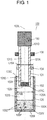
- FIG. 1 is a cross-sectional view of filter device 100 according to Exemplary Embodiment 1.
- Filter device 100 which is a blood filter device includes container 105 having a tubular shape having side wall 105A extending along reference axis 100L, and bottom 105B positioned on reference axis 100L, and has opening 105C.
- Container 105 has inner space 105S configured to store sample 100X therein.
- Sample 100X contains liquid component 100Y and plural solid components 100P and 100Z which are mixed and suspended in liquid component 100Y.
- Filter device 100 is configured to filter sample 100X so as to remove solid components 100Z as filtered-out substances from sample 100X and to allow liquid component 100Y and solid components 100P as a filtrate to pass through the filter device.
- Solid components 100Z are filtered-out substances and are filtered out by filter device 100 while solid components 100P are non-filtered-out substances which are not filtered out by filter device 100.
- Filter device 100 includes container 105, tube 101 configured to be inserted into inner space 105S of container 105, and filter part 102 provided inside tube 101.
- Tube 101 extends along reference axis 100L, and has opening ends 101C and 101D opposite to each other on reference axis 100L and inner space 101S communicating with the outside of tube 101 through opening ends 101C and 101D.
- Filter part 102 is located near opening end 101C or 101D of tube 101, and closes tube 101.
- Cap 103 closes opening end 101D of tube 101.
- Filter device 100 includes a capturing-retaining mechanism configured to prevent solid components 100Z captured by filter part 102 from being released and removed from filter part 102. As shown in FIG. 1 , for example, the capturing-retaining mechanism is configured such that, when tube 101 is inserted into container 105, an average mobility of solid components 100Z in filter part 102 is constant. More specifically, the capturing-retaining mechanism allows sample 100X to pass through filter part 102 at a constant pressure when tube 101 is inserted into container 105.
- Solid components 100Z are captured by filter part 102 by chemical bonding or physical capturing.
- a kind of the chemical bonding is not particularly limited, and the chemical bonding may be, e.g. covalent bonding, ionic bonding, hydrogen bonding, bonding by Van der Waals force.
- the physical capturing refers to capturing based on a structural factor, such as a size of pores in the material, of a material for forming filter part 102.
- the average mobility of solid components 100Z in filter part 102 refers to an average of moving speed of solid components 100Z in response to an external force which acts on solid components 100Z in filter part 102.
- Filter device 100 according to Embodiment 1 is operable such that the average mobility is constant.
- a pressure which is applied to sample 100X when sample 100X passes through filter part 102 is constant within a range where filter part 102 can maintain a capturing force for capturing solid components 100Z when the filtered-out substances, that is, solid components 100Z are filtered out.
- the pressure does not rapidly change.
- the pressure ranges from several kPa to several tens kPa.
- the shape of a cross section of tube 101 along a line perpendicular to reference axis 100L may be a circular shape, an elliptical shape, a rectangular shape, a trapezoidal shape, a polygonal shape, or an arbitrary shape surrounded by a closed curve.
- Tube 101 is made of, for example, glass, such as quartz glass, borosilicate glass, soda-lime glass, potash glass, crystal glass, uranium glass, or acrylic glass, or made of a resin, such as polypropylene, polyurethane, polyvinyl chloride, polyvinyl acetate, polytetrafluoroethylene, acrylonitrile butadiene styrene, polyacetal, polybutylene terephthalate, polyolefin, polystyrene, polydimethylsiloxane, polyamide, polycarbonate, polyethylene terephthalate, polyphenylene sulfide, polyether ether ketone, or polymethyl methacrylate.
- glass such as quartz glass, borosilicate glass, soda-lime glass, potash glass, crystal glass, uranium glass, or acrylic glass
- a resin such as polypropylene, polyurethane, polyvinyl chloride, polyvinyl acetate, polyt
- An inner wall of tube 101 preferably has hydrophilicity.
- the inner wall of tube 101 may preferably have high hydrophilicity.
- the following treatment may be used.
- Treatment may be, for example, plasma treatment with an oxygen gas or the like, the formation of composites made of hydrophilic nanoparticles or a surfactant, the formation of ultrafine unevenness, the formation of a silica-based film containing water glass or the like as a main component, the formation of a resin-based film using various hydrophilicity resins (water-soluble photosensitive resins), a wet process using a drastic medicine such as chromic anhydride or a sulfuric acid, optical surface treatment with ultra violet rays (UV ozone method), treatment with a siloxane-based static electricity prevention agent, or electrolytic polymer coating.
- tube 101 is stored at lower temperature, in freezing state, or in water.
- Filter part 102 is provided on the inner wall of tube 101.
- Filter part 102 is provided at opening end 101C or near opening end 101C of tube 101.
- Filter part 102 provided at such a position allows tube 101 to collect liquid component 100Y which is filtered in inner space 101S of tube 101 so that tube 101 can be effectively used as a collecting container.
- Filter part 102 is joined to tube 101 such that a leakage can be prevented.
- Filter part 102 may be made of nano-fiber, non-woven fabric, or a porous body made of polymer, an organic compound, an inorganic compound, or an inorganic oxide.
- Filter part 102 may be made of a silicon oxide which mainly contains silicon oxide.
- Filter part 102 is preferably made of amorphous silicon dioxide.
- Filter part 102 may be made of glass, such as borosilicate glass or soda-lime glass, or made of a resin, such as polypropylene, polyurethane, polyvinyl chloride, polyvinyl acetatepolyacetal, or polystyrene, besides silicon dioxide.
- the material for forming filter part 102 is not limited to above materials.
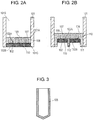
- FIG. 2A is an enlarged cross-sectional view of filter device 100.
- Filter part 102 has surface 102A and surface 102B opposite to surface 102A.
- Surface 102A faces inner space 101S of tube 101.
- Filter device 100 may include thin plate 108 provided on surface 102A of filter part 102.
- Thin plate 108 has surface 110 and surface 109 opposite to surface 110.
- Surface 110 is positioned on surface 102A of filter part 102.
- At least one aperture 107 which passes through thin plate 108 from surface 109 to surface 110 is formed in thin plate 108.
- Filter part 102 covers surface 110 of thin plate 108 and openings of apertures 107.
- Thin plate 108 provided on surface 102A of filter part 102 can increase strength of filter part 102.
- Thin plate 108 may be provided on surface 102B of filter part 102, thereby providing the same effects.
- Plural apertures 107 may be formed in thin plate 108. The number of apertures 107 is determined corresponding to the application where filtering is used.
- Filter part 102 and thin plate 108 be preferably bonded to each other.
- Filter part 102 and thin plate 108 bonded to each other can prevent filter part 102 from moving during filtering.
- Filter part 102 and thin plate 108 may preferably be directly bonded to each other.
- “filter part 102 and thin plate 108 are directly bonded to each other” refers to a state where filter part 102 is directly formed on thin plate 108 and atoms or molecules which constitute thin plate 108 and atoms or molecules which constitute filter part 102 are directly bonded to each other.
- the clause, "filter part 102 and thin plate 108 are directly bonded to each other” often refers to a state where covalent bonding is made between atoms.
- filter part 102 is made of fibrous substances made of silicon.
- Filter part 102 made of the fibrous substances made of silicon allows silicon atoms of thin plate 108 to be bonded to silicon atoms in the fibrous substances by covalent bonding along with oxygen molecules in an atmosphere where the fibrous substances are formed, and thereby, filter part 102 and thin plate 108 can be directly bonded to each other.
- Filter part 102 and thin plate 108 may be indirectly bonded to each other with an adhesive agent.
- FIG. 2B is an enlarged cross-sectional view of filter device 100.
- Filter device 100 may further include wall part 111 having an annular shape surrounding the entire periphery of filter part 102 along tube 101.
- Wall part 111 formed unitarily with the periphery of filter part 102 allows filter part 102 to be easily held and bonded to tube 101 when filter part 102 is installed to tube 101.
- Wall part 111 has a shape which conforms with a shape of filter part 102 so as to continuously surround the periphery of filter part 102.
- the shape of wall part 111 may be a circular annular shape or a polygonal annular shape, such as a triangular annular shape or a rectangular annular shape.
- Reinforcing part 112 may be formed on portions of surface 110 of thin plate 108 except for wall part 111 and apertures 107 such that reinforcing part 112 is connected with thin plate 108.
- Reinforcing part 112 has a plate shape extending in a direction perpendicular to the surface of thin plate 108, for example, and reinforcing part 112 is also connected to a side surface of wall part 111. This configuration allows a pressure applied to thin plate 108 to be further dispersed, hence preventing breakage of thin plate 108.
- reinforcing part 112 is preferably provided on surface 110 of thin plate 108. Plural reinforcing parts 112 may be provided, thereby improving pressure resistance of thin plate 108 against a force applied to thin plate 108 in the direction perpendicular to thin plate 108.
- a Silicon On Insulator (SOI) substrate in which a silicon layer is made of silicon (100) as a substrate is preferably used for manufacturing filter part 102.
- the SOI substrate has a three-layered structure including a silicon layer, a silicon dioxide layer provided on the silicon layer, and another silicon layer provide on the silicon dioxide layer so as to face the silicon layer across the silicon dioxide layer.
- the silicon dioxide layer can function as an etching-stop layer which stops etching during performing etching processing. Further, the silicon dioxide layer has high hydrophilicity, and hence, can easily suppress the generation of bubbles when sample 100X passes through filter part 102, and can easily remove the generated bubbles. Accordingly, the measurement with high accuracy can be realized.
- the thickness of silicon dioxide layer may preferably range from 0.5 to 10 ⁇ m from a viewpoint of a thickness which the silicon dioxide layer is required to have as an etching-stop layer and productivity.
- a silicon dioxide layer which functions as the etching-stop layer is made of a silicon dioxide layer which is formed by thermal oxidation.
- the silicon dioxide layer may be made of a silicon dioxide layer which is formed by other methods, such as a chemical vapor deposition (CVD) method, a sputtering method, or a chemical solution deposition (CSD) method or a doped oxide layer such as a so-called phosphorus silicon glass (PSG) layer doped with phosphorus or a boron phosphorus silicon glass (BPSG) layer which is doped with phosphorus and boron.
- the etching-stop layer is not limited to the above-mentioned layer which mainly contains silicon dioxide.
- a layer made of inorganic oxide or inorganic nitride, such as silicon nitride, silicon oxynitride or aluminum oxide, having an etching rate greatly different from an etching rate of silicon may function as the etching-stop layer.
- the substrate for manufacturing filter part 102 is an SOI substrate which contains silicon (100).
- the substrate for manufacturing filter part 102 may be a silicon (110) substrate, a silicon (111) substrate, or a silicon substrate having the different plane orientation.
- an amorphous silicon substrate used as the substrate can suppress a phenomenon that thin plate 108 which receives a largest force at the time of filtering is liable to be broken along the plane orientation.
- other substrates such as a glass substrate or a substrate made of a film resin, may be used besides the silicon substrate. From a viewpoint of workability and general-purpose use property, a substrate which contains silicon (100) can be used as the substrate for manufacturing filter part 102.
- the thickness of thin plate 108 may preferably range approximately from 5 to 150 ⁇ m.
- a desired number can be selected as the number of apertures 107.
- the number of apertures 107 is large, a filtered sample or sample 100X can easily pass through filter part 102.
- the number of apertures 107 is preferably large.
- Plural apertures 107 formed in surface 109 of thin plate 108 may preferably be arranged in a honeycomb pattern. This arrangement nay increase the number of apertures 107 formed in thin plate 108 per unit area without reducing strength of thin plate 108.
- the diameter of aperture 107 can be adjusted to a value suitable for suppressing the generation of resistance in a flow passage when sample 100X passes through aperture 107.
- the diameter of aperture 107 may preferably be not smaller than 3 ⁇ m.
- filter part 102 is formed using the fibrous substances made of silicon oxide which mainly contains silicon oxide
- filter part 102 may preferably be manufactured by a vaporized substrate deposition (VSD) method or a vapor liquid solid (VLS) method.
- VSD vaporized substrate deposition
- VLS vapor liquid solid
- filter part 102 is manufactured using an oxidative gas, such as oxygen or ozone, and a material which mainly contains silicon.
- silicon monoxide is evaporated from the material mainly containing silicon, and thereafter, the evaporated silicon monoxide adheres onto a surface of the material again and coagulates so that silicon dioxide can grow. At this moment, while silicon monoxide spreads on the entire surface of the silicon layer, silicon monoxide locally adheres again to places where a catalyst layer is formed, and is bonded to oxygen so that fibrous substances mainly containing silicon dioxide grows from these places.
- Atmosphere of low oxygen concentration refers to an atmosphere at the time of performing heat treatment where an oxygen partial pressure is low. Even in such a reduced-pressure atmosphere where the pressure is lower than the atmospheric pressure, oxygen may be replaced with another gas. This gas may be, e.g. nitride, argon, carbon or monoxide. Unlike oxygen and ozone, these gasses have low oxidizability. When a partial pressure of oxygen is extremely low, silicon monoxide cannot be generated. Accordingly, a partial pressure of oxygen preferably ranges from 10 -2 Pa to several thousands Pa.
- the thickness of the fibrous substances of filter part 102 may preferably range approximately from 0.01 to 2.0 ⁇ m.
- the fibrous substances are directly bonded to thin plate 108, and are formed densely such that the fibrous substances are entangled with each other. Fibrous substances which are branched in various directions may be mixed in the fibrous substances.
- filter part 102 Since fibrous substances are entangled with each other and some fibrous substances are branched, filter part 102 is strongly or firmly formed on surface 109 of thin plate 108. Further, the fibrous substances are entangled with each other in bent shapes so that gaps are formed between the fibrous substances such that the gaps are easily filled with solid components 100Z from various directions including areas above the openings of apertures 107 formed in surface 109.
- the thickness of fibrous substances is not limited to a constant, and the fibrous substances may include fibrous substances having various thicknesses.
- the thickness of the fibrous substances may preferably be gradually increased in the direction toward thin plate 108 from distal ends of the fibrous substance.
- the shortest distance of the gap between the fibrous substances is smaller than a diameter of solid component 100Z to be captured.
- Solid components 100Z out of solid components 100Z contained in sample 100X having a maximum diameter larger than a size of pores formed between the fibrous substances are captured by the fibrous substances while solid components 100P having a maximum diameter smaller than the size of the pores formed between the fibrous substances pass through the fibrous substances as non-filtered-out substances.
- This configuration can separate the non-filtered-out substances (solid components 100P) from the filtered-out substances (solid components 100Z) in sample 100X.
- the non-filtered-out substances (solid components 100P) can easily deform, since the non-filtered-out substances (solid components 100P) deform in the course of passing through the pores formed between the fibrous substances, the non-filtered-out substances (solid components 100P) can be extracted into the filtrate.
- solid components 100P can pass through apertures 107 even when the maximum diameter of the non-filtered-out substances (solid components 100P) is larger than the diameter of apertures 107.
- the size of pores formed between the fibrous substances may preferably a value ranging from 1 ⁇ m to 6 ⁇ m.
- the size of pores ranging from 1 ⁇ m to 6 ⁇ m allows filter part 102 to pass only red blood cells which are the non-filtered-out substances through filter part 102 while filter part 102 can prevent white blood cells which are the filtered-out substances from passing through filter part 102 by capturing the white blood cells.
- the diameter of apertures 107 is preferably not smaller than 3 ⁇ m.
- the thickness of filter part 102 preferably ranges from 1 ⁇ m to 1000 ⁇ m. However, the thickness of filter part 102 may be not smaller than 1000 ⁇ m according to the amount of the filtered-out substances.
- the formation of layers is not limited to a single layer, and fibrous substances made of different materials or having different shapes may be laminated to each other.
- Surface treatment may be applied to filter part 102. That is, the treatment such as the formation of a film by a coupling reaction using an organic silane-based compound, an organophosphonate compound, or a resin-based compound or electrolytic polymer coating by a mutual lamination method may be applied to filter part 102.
- Container 105 for storing sample 100X has a bottom, and has a tubular shape. As long as tube 101 can be inserted into container 105, the size of container 105 is not particularly limited.
- Container 105 is made of, for example, glass, such as quartz glass, borosilicate glass, soda-lime glass, potash glass, crystal glass, uranium glass or acrylic glass, or a resin, such as polypropylene, polyurethane, polyvinyl chloride, polyvinyl acetate, polytetrafluoroethylene, acrylonitrile butadiene styrene, polyacetal, polybutylene terephthalate, polyolefin, polystyrene, polydimethyl siloxane, polyamide, polycarbonate, polyethylene terephthalate, polyphenylene sulfide, polyetheretherketone or polymethyl methacrylate.
- glass such as quartz glass, borosilicate glass, soda-lime glass, potash glass, crystal glass, uranium glass or acrylic glass
- a resin such as polypropylene, polyurethane, polyvinyl chloride, polyvinyl acetate, polytetrafluoroethylene,
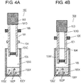
- FIG. 3 is a cross-sectional view of another container 105 of filter device 100 according to Embodiment 1.
- a bottom surface of container 105 has a conical shape such that the center of the bottom surface projects toward the outside of the container.
- the bottom surface of container 105 having such a shape can reduce an amount of remaining sample 100X.
- the bottom surface of container 105 may have a hemispherical shape.
- the bottom surface of container 105 has a conical shape
- a tapered angle an angle formed by a side surface of a conical shape and the bottom surface
- the amount of remaining sample 100X becomes large. Accordingly, such a shape with a small vertex angle is not preferable.
- a material of container 105 is not limited. However, when hydrophobicity is imparted to a surface of the inner wall of container 105, a large angle of wettability can be maintained (a meniscus can be maintained in a convex shape) and hence, sample 100X can continue contacting filter part 102 even when an amount of sample 100X is small. Accordingly, it is preferable to use a material which exhibits hydrophobicity.
- a contact angle formed with the surface of the inner wall of container 105 may preferably be not smaller than 60 degrees.
- Sample 100X is a liquid containing solid components 100P and 100Z. Solid components 100Z which are target components are trapped by filter part 102. Sample 100X contains blood and a material derived from, e.g. living organisms.
- the capturing-retaining mechanism configured to allow sample 100X to pass through filter part 102 at a constant pressure when tube 101 is inserted into container 105 includes, e.g. projection 104 formed on an outer circumference of tube 101, as shown in FIG. 1 .
- Projection 104 surrounds a peripheral edge of the outer circumference of tube 101.
- the shape of an outer circumference of projection 104 is substantially identical to the shape of an inner circumference of container 105.
- the outer circumference of projection 104 is a circular shape.
- Projection 104 is formed on the peripheral edge of the outer circumference of tube 101.
- a recess indented toward the inside of tube 101 may be formed in the peripheral edge of the outer circumference of tube 101.
- projection 104 is formed on the recess.
- Outermost diameter L104 of projection 104 is not smaller than inner diameter L105 of container 105. That is, in order to prevent sample 100X and air from leaking from the outer periphery of projection 104 when tube 101 is inserted into container 105, projection 104 has a size allowing a side surface of projection 104 to enter in container 105. Projection 104 resiliently contacts an inner wall of container 105 and hermetically closes a space in container 105 together with an outer wall surface of tube 101.
- Projection 104 is made of a deformable material, that is, a material having resiliency.
- projection 104 is made of an O-ring.
- Projection 104 is made of, e.g. a resilient rubber, such as silicone rubber, fluororubber, urethane rubber, natural rubber, chloroprene rubber, nitrile rubber, ethylene-propylene rubber, butyl rubber, chlorosulfonated polyethylene rubber, acrylic rubber, isoprene rubber, epichlorohydrin rubber, or butadiene rubber.
- a resilient rubber such as silicone rubber, fluororubber, urethane rubber, natural rubber, chloroprene rubber, nitrile rubber, ethylene-propylene rubber, butyl rubber, chlorosulfonated polyethylene rubber, acrylic rubber, isoprene rubber, epichlorohydrin rubber, or butadiene rubber.
- projection 104 is inserted into container 105 so that a space defined in container 105 can be hermetically sealed.
- Projection 106 is provided on the outer circumference of tube 101 at a position above projection 104. When tube 101 is inserted into container 105, projection 106 is stopped at an end portion of the opening of container 105. This prevents tube 101 from being inserted further into container 105.
- the distance between projection 104 and projection 106 is fixed, and hence, variations in pressure in a hermetically sealed space of respective filter devices 100 can be reduced before filtering.
- projection 106 is stopped at a flat surface at the end portion of container 105.
- An undulation which fits to projection 106 may be formed in the end portion of container 105.
- projection 106 and the end portion of the opening of container 105 may have a threaded structure.
- the position of projection 106 is determined such that sample 100X filled in container 105 does not go beyond projection 104 when tube 101 is inserted into container 105.
- a lower surface of filter part 102 may not preferably reach the bottom surface of container 105.
- filtering efficiency is deteriorated.
- Cap 103 is provided at opening end 101D of tube 101 opposite to opening end 101C to which filter part 102 is joined. Cap 103 is easily removable from opening end 101D of tube 101. Cap 103 closes opening end 101D of tube 101.
- Cap 103 can increase an inner pressure of container 105 without causing filter part 102 to contact sample 100X when tube 101 is inserted into container 105. This configuration can reduce a length of container 105. After the inner pressure of container 105 rises to a predetermined pressure, opening end 101D of tube 101 is opened by removing cap 103, and sample 100X can be filtered at a predetermined pressure, hence stabling the capturing performance of filter part 102.
- filter device 100 may include a metal seal, a rubber plug, a leak valve, or a leak hole which can close and open opening end 101D of tube 101 instead of cap 103.
- cap 103 In the case that the outer diameter of cap 103 is larger than the outer diameter of tube 101, cap 103 is stopped at the end portion of opening of container 105. In this case, cap 103 functions as projection 106 even when filter device 100 does not include projection 106.
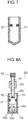
- FIGs. 4A to 4D are cross-sectional views of filter device 100 according to Embodiment 1 for illustrating a filtering method used with filter device 100.
- sample 100X is put in container 105. Then, tube 101 is inserted into container 105 through upper opening 105C of container 105 provided at the upper part of container 105.
- projection 104 formed on tube 101 is inserted into container 105 so that hermetically sealed space 105Y is formed by sample 100X in container 105, projection 104, and the outer surface of tube 101.
- tube 101 is inserted further into container 105.
- hermetically sealed space 105Y in container 105 is gradually decreased while a pressure in hermetically sealed space 105Y is gradually increased.
- projection 106 is contacts end portion 105D of opening 105C of container 105, the insertion of tube 101 into container 105 is stopped.
- cap 103 mounted on tube 101 is removed from opening end 101D of tube 101. Due to the removal of cap 103, hermetically sealed space 105Y in container 105 is released from the status that the container is compressed by an amount corresponding to a volume of hermetically sealed space 105Y. At this moment, a pressure in hermetically sealed space 105Y intends to return to an atmospheric pressure while a pressure compressed in hermetically sealed space 105Y is maintained so that the pressure tends to push out sample 100X from tube 101. As a result, sample 100X which is pushed out into tube 101 is filtered by passing through filter part 102, and is stored in tube 101 as filtrate 100Q.
- sample 100X is sucked into tube 101 through filter part 102 by a capillary phenomenon.
- sample 100X While filtering sample 100X through filter part 102, it is necessary to take into account a surface tension of sample 100X and gravity applied to sample 100X.
- Sample 100X is stored in container 105 while solid components 100Z as the filtered-out substances are previously contained in sample 100X.
- sample 100X may be prepared in container 105 by previously putting a solvent, such as a dilution of the filtered-out substances, in container 105, and then, the filtered-out substances which have been absorbed in, e.g. a sponge are mixed with the solvent.
- the filtered-out substances (solid components 100Z) can be dyed by mixing a dying solution in sample 100X if necessary.
- FIG. 5 is a cross-sectional view of another filter device 190 according to Embodiment 1.
- a diameter of tube 101 may be changed at projection 104 as a boundary. That is, the diameter of a portion of tube 101 directed toward the outside of container 105 from projection 104 is larger than a diameter of a portion of tube 101 directed toward the inside of container 105 from projection 104.
- tube 101 having such a shape does not allow projection 104 to be displaced, and hence, the position of tube 101 and a volume of hermetically sealed space 105Y can be easily controlled.
- tube 101 having such a shape allows projection 104 to be easily positioned at the time of manufacturing filter device 190. Accordingly, it is preferable to form tube 101 into such a shape.
- filter device 100 includes the capturing-retaining mechanism which is configured to allow sample 100X to pass through filter part 102 at a constant pressure when tube 101 is inserted into container 105.
- This configuration maintains a pressure in container 105 during the operation of filtering at a constant value without applying an abnormal pressure to filter part 102. That is, in filter device 100, hermetically sealed space 105Y having a pressure not smaller than an atmospheric pressure is formed in container 105. By using a force generated when the pressure returns to the atmospheric pressure (differential pressure), sample 100X is filtered by passing through filter part 102.
- a force applied to the captured substances which are solid components 100Z captured by filter part 102 does not suddenly increase, and hence, can suppress the occurrence of a phenomenon that the captured substances which are solid components 100Z captured by filter part 102 are removed from filter part 102, thereby stabilizing the capturing performance of filter part 102, and enhancing filter performance of filter device 100.
- filter device 1 shown in FIG. 14 cannot prevent an abnormal pressure from being applied to filter part 5, and needs to connect, to filter device 1, a device outside filter device 1 for preventing it. As a result, filter device 1 does not only have a large size but also complicate the mechanism of filter device 1. Accordingly, filter device 1 cannot be used conveniently.
- Conventional filter device 1 upon being applied to an extremely small filter device, may cause filter part 5 to lose its capture performance.
- filter device 1 In the case that filter device 1 is extremely small, when a sample is continuously pressurized at a constant flow rate, a pressure applied to liquid having blood cells suspended therein is gradually increased. As a result, a pressure applied to captured substances is increased, so that the captured substances captured by filter part 5 may be removed from filter part 5 to outlet 3.
- filter part 5 all of liquid having blood cells suspended therein passes through filter part 5, and hence, the substances captured by filter part 5 are removed from filter part 5 due to release or removal of the captured substances, and the captured substances are removed to outlet 3. As a result, filter performance of filter device 1 is deteriorated.
- Filter device 100 includes the capturing-retaining mechanism which can control a pressure applied to sample 100X. Even when filter device 100 is not connected to a device for controlling a pressure provided outside filter device 100, it is possible to control the pressure only by filter device 100. Further, filter device 100 does not require the complicated mechanism, and hence, the operation of filter device 100 is performed simply and easily.
- filter device 100 is configured to filter sample 100X containing liquid component 100Y and solid components 100Z mixed with liquid component 100Y.
- Filter device 100 includes container 105 configured to store sample 100 therein, tube 101 configured to be inserted into container 105, filter part 102 provided inside tube 101, and a capturing-retaining mechanism.
- filter part 102 is configured to allow the stored sample 100 to pass through filter part 102 so as to capture solid components 100Z and to allow liquid component 100Y to pass through filter part 102.
- the capturing-retaining mechanism is configured to prevent the captured solid components 100Z from being removed from filter part 102 when sample 100X passes through filter part 102.
- the capturing-retaining mechanism may be configured such that an average mobility of solid components 100Z in filter part 102 when sample 100X passes through filter part 102 is constant.
- the capturing-retaining mechanism may be configured such that a pressure applied to sample 100X when sample 100X passes through filter part 102 is constant.
- Projection 104 the capturing-retaining mechanism, being provided on an outer circumference of tube 101 and surrounding the outer circumference of tube 101.
- Projection 104 has an outermost diameter not smaller than an inner diameter of container 105.
- Container 105 has an opening having tube 101 inserted therein.
- the capturing-retaining mechanism further includes projection 106 provided on tube 101. Projection 106 being configured to contact an end portion of container 105 facing the opening so as to prevent tube 101 from being inserted into container 105 by a depth not smaller than a predetermined depth.
- FIG. 6 is a cross-sectional view of filter device 200 which is a blood filter device according to Exemplary Embodiment 2.
- Filter device 200 includes projection 204 and stopper 221 instead of projections 104 and 106 of filter device 100 according to Embodiment 1.
- Filter device 200 includes a capturing-retaining mechanism configured to prevent solid components 100Z which are captured substances captured by filter part 102 from being removed from filter part 102 due to release or removal of solid components 100Z when tube 101 is inserted into container 105.
- the capturing-retaining mechanism is configured such that a portion of sample 100X does not pass through filter part 102 and remains in container 105 when tube 101 is inserted into container 105.
- FIG. 7 is a cross-sectional view of another container 105 of filter device 200 according to Embodiment 2.
- a bottom surface of container 105 has a conical shape such that the center of the bottom surface projects toward the outside. This shape can reduce the amount of the remaining portion of sample 100X.
- the bottom surface of container 105 may have a hemispherical shape instead.
- the bottom surface of container 105 has a conical shape
- a tapered angle an angle formed by a side surface of a conical shape and the bottom surface
- the amount of the remaining portion of sample 100X becomes large. Accordingly, such a shape is not preferable.
- the capturing-retaining mechanism of filter device 200 is configured such that a portion of sample 100X does not pass through filter part 102 and remains in container 105 when tube 101 is inserted into container 105.
- the capturing-retaining mechanism of filter device 200 includes projection 204 formed on an outer circumference of tube 101 and stopper 221 extending from an inner wall of container 105.
- projection 204 is stopped at a plane on stopper 221.
- undulations may be formed in projection 204 and stopper 221, and these undulations may be fitted to each other.
- projection 204 and stopper 221 may have a threaded engagement structure.
- the position of projection 204 is determined such that sample 100X put in container 105 does not go beyond stopper 221 when tube 101 is inserted into container 105.
- a lower surface of filter part 102 does not preferably reach bottom 105B of container 105.
- a distance from a bottom of container 105 to stopper 221 is larger than a length from projection 204 to a distal end of filter part 102.
- a size of projection 204 is determined to be a size which allows projection 204 to be inserted into container 105 to prevent that the occurrence of leakage of sample 100X or air from an outer periphery of projection 204 when tube 101 is inserted into container 105.
- FIGs. 8A to 8C are cross-sectional views of filter device 200 for illustrating a filtering method used with filter device 200.
- sample 100X is put in container 105. Then, tube 101 is inserted into container 105 through upper opening 105C of container 105 provided at the upper part of container 105.
- tube 101 is inserted into container 105 until projection 204 fixed to tube 101 is stopped with stopper 221 provided inside container 105.
- sample 100X is filtered by passing through filter part 102.
- Filtrate 100Q which is sample 100X filtered through filter part 102 is stored in inner space 101S of tube 101 at an upper portion of tube 101.
- Filtrate 100Q contains non-filtered-out substances (solid components 100P) and liquid component 100Y, and does not contain the filtered-out substances (solid components 100Z).
- sample 100X is sucked into tube 101 through filter part 102 by a capillary phenomenon.
- a filtering speed and an amount of sample 100X passing through filter part 102 both of which are dependent on a pressure (pressure-dependent) can be controlled by controlling a compression amount of air in the container. At this moment, the own weight of sample 100X is neglected, and hence, a pressure inside container 105 is maintained approximately constant.
- the filtering is finished while a portion of sample 100X remains in container 105.
- a volume compressed when tube 101 is inserted into container 105 is preferably not larger than a volume of sample 100X which passes through filter part 102.
- sample 100X In filtering sample 100X, it is necessary to take into account a surface tension of sample 100X and the gravity of sample 100X.
- the surface tension of sample 100X generated between sample 100X and an inner wall of tube 101 prevents a portion of sample 100X from passing through filter part 102 and being filtered.
- the compression volume is not larger than the sum of a volume of sample 100X which is filtered through filter part 102 and a volume of the portion of sample 100X which is not filtered.
- FIG. 9 is a cross-sectional view of filter device 200.
- the compression volume is volume V3 which is a difference obtained by subtracting volume V2 from volume V1.
- Volume V2 ranges from opening 105C of container 105 to a portion of tube 101 positioned inside container 105.
- Volume V1 ranges from opening 105C of container 105 to stopper 221.
- An amount of sample 100X which can pass through filter part 102 is smaller than a total amount of sample 100X put into container 105. That is, the sum of a volume of sample 100X which is filtered through filter part 102 and a volume of the portion of sample 100X which is not filtered is the volume of sample 100X.
- filter device 200 Due to the above-mentioned configuration, in filter device 200, the filtering is finished in a state where the portion of sample 100X remains in container 105.
- Sample 100X which is not filtered and thus remaining in container 105 has a volume in which a height of an upper surface of sample 100X remaining in container 105 is not lower than a height from a bottom of container 105 to a lower surface of filter part 102 after tube 101 is inserted into container 105. That is, sample 100X contacts filter part 102 even after the filtering is finished. As a result, sample 100X always contacts filter part 102.
- Sample 100X is stored in container 105 in a state where solid components 100Z as the filtered-out substances are previously contained in sample 100X.
- sample 100X may be prepared inside container 105 by previously putting a solvent, such as a dilution of the filtered-out substances, in container 105 and then by mixing, with the solvent, the filtered-out substances which have been absorbed in a sponge.
- filter device 200 As described above, in filter device 200 according to Embodiment 2, air filling a space from opening 105C of container 105 to stopper 221 can be compressed by stopper 221 provided inside container 105 and projection 204 formed on tube 101 which is inserted into container 105. Accordingly, sample 100X can be filtered by causing sample 100X to pass through filter part 102 by a pressure difference between the compressed air and an atmospheric air.
- a length from filter part 102 to projection 204 is shorter than a length from the bottom of container 105 to stopper 221. This configuration can allow sample 100X to remain in container 105 even after the filtering is finished. Accordingly, sample 100X can be filtered without losing capture performance of filter part 102.
- filter device 1 shown in FIG. 14 when all the sample is filtered, a capture performance of filter part 5 may be lost so that the captured substances (solid components 100Z) which are captured by filter part 5 may be removed from filter part 5 due to release or removal of the captured substances, and are removed to an outlet.
- a phase of the pores in filter part 5 changes from a liquid phase to a gas phase, a viscosity of the sample is lowered, and hence, a flow speed (flow amount) of the sample is increased, thereby a force applied to the captured substances is increased and exceeds a force to absorb the captured substances into filter part 5.
- the captured substances are specimens, particularly specimens derived from a living body
- a deformation amount of specimens per se is accelerated, and hence, the capture performance is deteriorated.
- hydrophilicity of a capturing surface of filter part 5 is lowered so that a surface tension is greatly decreased, thereby a state of the capturing surface of filter part 5 is remarkably changed.
- Such a change is considered to bring about a change in adhesiveness (charge coupling, chemical bonding or the like) of the surface.
- pores formed in filter part 102 are always filled with liquid component 100Y during filtering. This configuration allows a portion of sample 100X to remain in container 105 without filtering all sample 100X through filter part 102, so that sample 100X can remain in filter part 102.
- filter part 102 Since the inside of filter part 102 is filled with sample 100X, a force applied to the captured substances (solid components 100Z) captured by filter part 102 is not suddenly increased. Accordingly, the filtering can be finished while preventing the captured substances from being removed from filter part 102. As a result, a filter performance of filter device 200 can be enhanced.
- a pressure or a flow rate at which filtering is performed can be controlled by controlling a compression amount of air in a space from opening 105C of container 105 to stopper 221 and a speed at which air is leaked from cap 103. Accordingly, the stability of capture performance of filter part 102 is enhanced.
- Cap 103 which is easily removable is mounted on opening end 101D of tube 101 opposite to opening end 101C to which filter part 102 is joined.
- Cap 103 can increase an inner pressure of container 105 without causing filter part 102 to contact sample 100X when tube 101 is inserted into container 105, hence reducing a length of container 105. Further, the inner pressure of container 105 rises to a predetermined pressure, and then, cap 103 is removed, hence allowing sample 100X to be filtered at a predetermined pressure. Accordingly, filter part 102 can easily exert capture performance stably.
- filter device 200 may include a metal seal, a rubber plug, a leak valve, or a leak hole which can close and open opening end 101D of tube 101 instead of cap 103.
- the capturing-retaining mechanism which is configured such that a portion of sample 100X does not pass through filter part 102 and remains in container 105 includes projection 204 formed on the outer circumference of tube 101 and stopper 221 which extends from the inner wall of container 105 and stops projection 204.
- Filter device 200 according to Embodiment 2 is not limited to the configuration which includes a control mechanism for causing sample 100X to remain inside container 105 as described above. That is, filter device 200 may include a control mechanism which causes sample 100X to take out from container 105.
- the capturing-retaining mechanism is configured such that a portion of sample 100X does not pass through filter part 102 and remains in container 105 when tube 101 is inserted into container 105.
- the capturing-retaining mechanism includes projection 204 formed on the outer circumference of tube 101 and stopper 221 provided on the inner wall of container 105. Stopper 221 is configured to contact projection 204 when tube 101 is inserted into container 105.
- a compression volume when tube 101 is inserted into container 105 is not larger than an amount of sample 100X which passes through filter part 102.
- FIG. 10 is a cross-sectional view of filter device 300 according to Example 1 which does not form part of the invention but is useful for understanding the invention.
- components identical to those of filter devices 100 and 200 according to the first Embodiments 1 and 2 shown in FIGs. 1 to 9 are denoted by the same reference numerals.
- Filter device 300 includes insertion mechanism 331 for inserting filter part 102 into container 105 instead of tube 101 of filter device 100 according to Embodiment 1 or tube 101 of filter device 200 according to Embodiment 2.
- Filter part 102 is inserted into container 105 by inserting insertion mechanism 331 into container 105 so that filter part 102 can be inserted into sample 100X stored in container 105.
- Sample 100X is filtered by passing through filter part 102 to acquire filtrate 100Q.
- Filtrate 100Q is collected in an upper portion of container 105, that is, on a side of filter part 102 opposite to a bottom of container 105.
- filter part 102 An outer periphery of filter part 102 is covered by wall part 311.
- Filter part 102 is joined to wall part 311 so as to prevent the occurrence of leakage between filter part 102 and wall part 311.
- Thin plate 108 having apertures 107 therein shown in FIGs. 2A and 2B may be provided on wall part 311.
- filter part 102 is provided on a lower surface or an upper surface of the thin plate.
- the thin plate provided on the lower surface or the upper surface of filter part 102 increases the strength of filter part 102.
- Wall part 311 and the thin plate may preferably have hydrophilicity.
- Insertion mechanism 331 can pressurize filter part 102 from above wall part 311. Insertion mechanism 331 is joined to filter part 102. By pushing insertion mechanism 331, filter part 102 is inserted into container 105.
- a plunger may be used as insertion mechanism 331.
- a pushing rod is provided at wall part 311 of filter part 102. By pushing the pushing rod, filter part 102 can be inserted into container 105.
- Filter device 300 includes a capturing-retaining mechanism configured such that, when insertion mechanism 331 is inserted into container 105 for storing sample 100X, a portion of sample 100X put in container 105 does not pass through filter part 102 and remains in container 105.
- the capturing-retaining mechanism allowing sample 100X to remain in container 105 includes, e.g. stopper 321 provided on an inner wall of container 105. Stopper 321 is configured to stop filter part 102 so as to prevent filter part 102 from contacting the bottom surface of container 105. Stopper 321 is configured to stop wall part 311 such that wall part 311 contacts stopper 321 when filter part 102 is inserted into container 105. Stopper 321 is provided at a position not lower than a height from the bottom surface of container 105 at which a predetermined volume of the remaining portion of the sample can be obtained.
- the non-filtered-out substances (solid components 100P) pass through filter part 102 and are stored in an upper portion of container 105. Accordingly, after filter part 102 is inserted into container 105, the non-filtered-out substances above filter part 102 and the non-filtered-out substances below filter part 102 inside container 105 leak only through filter part 102, and the non-filtered-out substances do not leak through wall part 311.
- insertion mechanism 331 is configured to insert filter part 102 into container 105 to cause the stored sample 100X pass through filter part 102 such that solid components 100Z are captured by filter part 102 and liquid component 100Y passes through filter part 102.
- Stopper 321 the capturing-retaining mechanism, extends from the inner wall of container 105 so as to stop filter part 102.
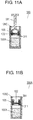
- FIG. 11A is a cross-sectional view of another filter device 390 according to Example 1.
- the capturing-retaining mechanism which allows sample 100X to remain in container 105 includes wall part 311 configured to prevent filter part 102 from reaching a bottom of container 105.
- Wall part 311 projects toward the bottom of container 105 from filter part 102. That is, a height of a lower surface of filter part 102 (a lower surface of the thin plate in the case where filter part 102 includes the thin plate) is higher than a height of a lower surface of wall part 311. That is, filter device 390 has a structure in which the lower surface of wall part 311 firstly contacts the bottom of container 105 by inserting filter part 102 into container 105. This configuration allows sample 100X to remain in a well portion formed by wall part 311.
- FIG. 11B is a cross-sectional view of still another filter device 390A according to Example 1.
- Filter device 390A shown in FIG. 11B includes weight 391 mounted on wall part 311 instead of insertion mechanism 331 of filter device 390 shown in FIG. 11A .
- Weight 391 mounted on wall part 311 can push filter part 102 by gravity. As a result, filter part 102 can be inserted into container 105 at a constant speed.
- weight 391 functions as an insertion mechanism for inserting filter part 102 into container 105.
- Weight 391 may preferably have a weight not smaller than the sum of a buoyancy of sample 100X and a fluid resistance. This configuration allows filter part 102 to sink in sample 100X to the bottom of container 105 while pressurizing sample 100X. Accordingly, sample 100X can be filtered by merely inserting filter part 102 having weight 391 and wall part 311 into container 105.
- the insertion mechanism configured to insert filter part 102 into container 105 includes weight 391 mounted on filter part 102.
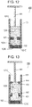
- FIG. 12 is a cross-sectional view of filter device 400 according to Example 2 which does not form part of the invention but is useful for understanding the invention.
- Filter device 400 according to Example 2 does not include container 105 configured to store sample 100X of the filter devices according to Embodiments 1 and 2 and Example 1. Instead, filter device 400 is configured such that tube 101 stores sample 100X.
- Filter part 102 is provided inside tube 101 so as to close tube 101. Sample 100X is stored above filter part 102 in tube 101, that is, in a space formed in the direction from filter part 102 toward opening end 101D of tube 101.
- Filter device 400 includes a capturing-retaining mechanism configured to prevent a portion of sample 100X stored between filter part 102 and pressurizing mechanism 441 from passing through filter part 102 and to cause the portion to remain between filter part 102 and pressurizing mechanism 441 when pressurizing mechanism 441 is inserted into tube 101.
- a plunger provided with a pushing rod shown in FIG. 12 can be used, for example.
- filter part 102 may preferably be provided at opening end 101C of tube 101.
- the capturing-retaining mechanism which allows sample 100X to remain in tube 101 is, for example, stopper 421 extending from an inner wall of tube 101. Stopper 421 is configured to stop pressurizing mechanism 441. A distance from filter part 102 to stopper 421 is determined according to a predetermined amount of the portion of sample 100X remaining in tube 101.
- sample 100X which is located between filter part 102 and pressurizing mechanism 441 stopped with stopper 421 on an inner wall of tube 101 and on a surface of pressurizing mechanism 441.
- sample 100X located between filter part 102 and pressurizing mechanism 441 stopped with stopper 421 remains in tube 101.
- the amount of the portion of sample 100X remaining in tube 101 between filter part 102 and pressurizing mechanism 441 stopped with stopper 421 depends on an inner diameter of tube 101. Accordingly, a surface tension of remaining sample 100X may preferably be larger than the gravity of sample 100X. In this case, the inner wall of tube 101 and the surface of pressurizing mechanism 441 may preferably have hydrophilicity.
- an air phase may not preferably formed in an interface between sample 100X and pressurizing mechanism 441. That is, pressurizing mechanism 441 may preferably contact sample 100X directly.
- a hydrophobic membrane may be preferably provided on a surface of pressurizing mechanism 441 contacting sample 100X (a lower surface of pressurizing mechanism 441 shown in FIG. 12 ). Although sample 100X in a liquid phase cannot pass through the hydrophobic membrane, an air phase can pass through the hydrophobic membrane. As a result, pressurizing mechanism 441 can directly contact sample 100X at the interface between sample 100X and pressurizing mechanism 441.
- a speed at which pressurizing mechanism 441 is inserted may preferably be identical to a speed of leakage from tube 101 and pressurizing mechanism 441.
- This configuration allows the interface of pressurizing mechanism 441 to contact sample 100X directly.
- sample 100X may be sucked into tube 101 from the outside of tube 101 through filter part 102, and sample 100X is pushed out after a distal end of filter part 102 is cleaned.
- the filtering condition shown in FIG. 12 can be obtained also by putting sample 100X into tube 101 up to opening end 101D.
- Sample 100X directly contacts pressurizing mechanism 441.
- a force in the upward direction generated by a surface tension on the inner wall of tube 101 is not smaller than the product obtained by multiplying a mass of sample 100X by the gravitational acceleration. This configuration allows sample 100X to remain in tube 101.
- Filter part 102 has surfaces 102B and 102A.
- Surface 102B faces opening end 101C of tube 101.
- Surface 102A faces opening end 101D.
- a thin plate having apertures provided therein may be provided on surface 102A or surface 102B of filter part 102.
- a surface tension acts on an outer periphery of a distal end of the aperture (outlet for filtrate 100Q).
- a tensile force generated by a surface tension may become larger than the gravity applied to a droplet of sample 100X.
- whether or not the droplet is dropped that is, whether or not sample 100X leaks through the aperture is relevant to a diameter of a neck portion of the droplet formed at the distal end of the aperture.
- a surface tension is a force which acts on the circumference, and hence, the droplet is not dropped if a tensile force generated by a surface tension of the neck portion is larger than the gravity applied to the droplet.
- filter device 400 in a state where pressurizing mechanism 441 stopped with stopper 421 contacts sample 100X completely, a surface tension of sample 100X acts on the inner wall of tube 101 or the surface of pressurizing mechanism 441 contacting sample 100X, and hence, allows sample 100X to remain in tube 101. As a result, filter device 400 can filter sample 100X without losing capture performance of filter part 102.
- the remaining amount of sample 100X can be controlled by adjusting a distance from filter part 102 to stopper 421, and hence, it is possible to allow an extremely small amount of sample 100X to remain in tube 101.
- sample 100X can remain in tube 101 even when pressurizing mechanism 441 does not contact sample 100X completely, that is, even when an air phase is formed between pressurizing mechanism 441 and sample 100X.
- tube 101 is configured to store sample 100X therein.
- Filter part 102 is configured to close tube 101.
- Pressurizing mechanism 441 is configured to pressurize the stored sample 100X so as to cause the stored sample 100X to pass through the filter part 102 such that the solid components 100Z are captured by the filter part 102 and the liquid component 100Y passes through the filter part 102.
- the capturing-retaining mechanism is configured to prevent a portion of the stored sample 100X from passing through the filter part 102 and to cause the portion of the stored sample 100X remain between the filter part 102 and the pressurizing mechanism, such that the captured solid components 100Z are not removed from the filter part when the sample 100X passes through the filter part 102.
- the capturing-retaining mechanism, stopper 441, extends from an inner wall of tube 101 as to stop the pressurizing mechanism 441.
- FIG. 13 is a cross-sectional view of another filter device 490 according to Example 2 which does not form part of the invention but is useful for understanding the invention.
- Filter device 490 shown in FIG. 13 further includes projections 442 which extend toward opening end 101D in the direction in which tube 101 extends from stopper 421 of filter device 400 shown in FIG. 12 .
- Apertures 443 are formed in pressurizing mechanism 441.
- Filter device 490 further includes movable plugs 444 which close apertures 443.
- Movable plug 444 is made of a movable rubber plug, cork plug, metal plug, resin plug or a lid, or a breakable membrane, such as a resin membrane, a rubber membrane, a metal membrane, or a fiber membrane.
- Pressurizing mechanism 441 compresses an air between sample 100X and pressurizing mechanism 441.
- Projections 442 may preferably extend toward opening end 101D in the direction in which a side wall of tube 101 extends. That is, apertures 443 may not preferably contact projections 442. In order to remove movable plugs 444 from aperture 443 of pressurizing mechanism 441, a length of projections 442 is larger than a length of apertures 443.
- an inner diameter of aperture 443 is larger than a diameter of projection 442.
- filter device 490 includes movable plugs 444 which are provided on pressurizing mechanism 441 and contact an air inside tube 101. While pressurizing sample 100X with pressurizing mechanism 441, projections 442 formed on stopper 421 are inserted into apertures 443 provided in pressurizing mechanism 441. When movable plugs 444 are removed by projections 442, the air compressed inside tube 101 can be released to an atmospheric air, and hence, allows sample 100X to remain in tube 101 due to a pressure equilibrium.
- a filter device is applicable to a device for extracting only a particular substance from a sample.
Landscapes
- Health & Medical Sciences (AREA)
- Life Sciences & Earth Sciences (AREA)
- Chemical & Material Sciences (AREA)
- Engineering & Computer Science (AREA)
- Biomedical Technology (AREA)
- Hematology (AREA)
- Analytical Chemistry (AREA)
- General Health & Medical Sciences (AREA)
- Physics & Mathematics (AREA)
- Chemical Kinetics & Catalysis (AREA)
- Biophysics (AREA)
- Biochemistry (AREA)
- Clinical Laboratory Science (AREA)
- Molecular Biology (AREA)
- Urology & Nephrology (AREA)
- Food Science & Technology (AREA)
- Medicinal Chemistry (AREA)
- Ecology (AREA)
- General Physics & Mathematics (AREA)
- Immunology (AREA)
- Pathology (AREA)
- Sampling And Sample Adjustment (AREA)
- Apparatus Associated With Microorganisms And Enzymes (AREA)
- Investigating Or Analysing Biological Materials (AREA)
Claims (3)
- Dispositif de filtre sanguin configuré pour filtrer un échantillon (100X) contenant un composant liquide (100Y) et une pluralité de composants solides (100Z) mélangés avec le composant liquide (100Y), le dispositif de filtre sanguin (100, 200) comprenant:un récipient (105) configuré pour stocker l'échantillon (100X) dans celui-ci;un tube (101) configuré pour être introduit dans le conteneur (105);une partie filtre (102) prévue à l'intérieur du tube (101), dans laquelle, lorsque le tube (101) est introduit dans le récipient (105), la partie filtre (102) est configurée pour laisser passer l'échantillon stocké (100X) à travers la partie filtre (102) de manière à capturer la pluralité de composants solides (100Z) et à permettre au composant liquide (100Y) de traverser la partie filtre (102);un mécanisme de capture-retenue (104, 106, 204, 221) configuré pour empêcher la pluralité des composants solides capturés (100Z) d'être retirés de la partie filtre (102) lorsque l'échantillon (100X) passe à travers la partie filtre (102); etun capuchon (103) prévu à une extrémité d'ouverture (101D) du tube (101) opposée à une extrémité d'ouverture (101C) à laquelle la partie filtre (102) est jointe et fermant l'extrémité d'ouverture (101D) du tube (101), le capuchon (103) étant configuré pour être amovible de l'extrémité d'ouverture (101D) du tube (101), dans lequel le capuchon (103) est configuré pour sceller hermétiquement le récipient (105) afin d'augmenter une pression interne du récipient (105) lorsque le tube (101) est introduit dans le récipient (105);dans lequel le récipient (105) comporte une ouverture (105C) dans laquelle est introduit le tube (101), etdans lequel le mécanisme de capture-retenue (104, 106, 204, 221) est structuré de telle sorte que:le mécanisme de capture-retenue (104, 106, 204, 221) comprendune première protubérance (104) prévue sur une circonférence extérieure du tube (101) et entourant la circonférence extérieure du tube (101), la première protubérance (104) ayant un diamètre le plus externe supérieur ou égal à un diamètre intérieur du récipient (105), etune seconde protubérance (106) prévue sur le tube (101), la seconde protubérance (106) étant configurée pour entrer en contact avec une partie d'extrémité du récipient (105) faisant face à l'ouverture (105C) de manière à empêcher l'introduction du tube (101) dans le récipient (105) d'une profondeur supérieure ou égale à une profondeur prédéterminée ou bien le mécanisme de capture-retenue (104, 106, 204, 221) comprend:une protubérance (204) prévue sur une circonférence extérieure du tube (101); etun bouchon (221) prévu sur une paroi interne du récipient (105), le bouchon (221) étant configuré pour venir au contact de la protubérance (204) lorsque le tube (101) est introduit dans le récipient (105).
- Dispositif de filtre sanguin selon la revendication 1, dans lequel le mécanisme de capture-retenue (104, 106, 204, 221) est configuré de sorte qu'une partie de l'échantillon (100X) ne traverse pas la partie filtre (102) et reste dans le récipient (105) lorsque le tube (101) est introduit dans le récipient (105).
- Dispositif de filtration de sang selon la revendication 2, dans lequel un volume comprimé du récipient (105) lorsque le tube (101) est introduit dans le récipient (105) est inférieur ou égal à une quantité de l'échantillon (100X) qui traverse la partie filtre (102).
Applications Claiming Priority (3)
| Application Number | Priority Date | Filing Date | Title |
|---|---|---|---|
| JP2012232592 | 2012-10-22 | ||
| JP2013008139 | 2013-01-21 | ||
| PCT/JP2013/006232 WO2014064921A1 (fr) | 2012-10-22 | 2013-10-22 | Dispositif à filtre |
Publications (3)
| Publication Number | Publication Date |
|---|---|
| EP2910944A1 EP2910944A1 (fr) | 2015-08-26 |
| EP2910944A4 EP2910944A4 (fr) | 2015-12-30 |
| EP2910944B1 true EP2910944B1 (fr) | 2018-09-26 |
Family
ID=50544306
Family Applications (1)
| Application Number | Title | Priority Date | Filing Date |
|---|---|---|---|
| EP13849029.7A Not-in-force EP2910944B1 (fr) | 2012-10-22 | 2013-10-22 | Dispositif à filtre |
Country Status (4)
| Country | Link |
|---|---|
| US (1) | US20150231536A1 (fr) |
| EP (1) | EP2910944B1 (fr) |
| JP (1) | JP6286674B2 (fr) |
| WO (1) | WO2014064921A1 (fr) |
Families Citing this family (14)
| Publication number | Priority date | Publication date | Assignee | Title |
|---|---|---|---|---|
| GB201411615D0 (en) * | 2014-06-30 | 2014-08-13 | Ge Healthcare Uk Ltd | Device and method for cell nuclei preparation |
| JP6680357B2 (ja) | 2016-06-30 | 2020-04-15 | 株式会社島津製作所 | 容器セットおよびそれを用いた試料調製方法 |
| JP6762028B2 (ja) * | 2016-10-04 | 2020-09-30 | メディカテック株式会社 | 採便容器、および、便検査装置 |
| CN212881367U (zh) * | 2016-12-08 | 2021-04-06 | 反应分析公司 | 样品小瓶组件和过滤器插入件 |
| JP6789107B2 (ja) * | 2016-12-28 | 2020-11-25 | 富士フイルム株式会社 | 血液検査キット及び血液分析方法 |
| KR101955708B1 (ko) | 2018-01-04 | 2019-03-07 | 주식회사 진시스템 | 핵산 추출튜브 및 이를 이용한 핵산 추출방법 |
| DE102018219379A1 (de) * | 2018-11-13 | 2020-05-14 | Sarstedt Ag & Co. Kg | Vorrichtung und Verfahren zur Gewinnung einer zellfreien Probenfraktion |
| WO2020196443A1 (fr) * | 2019-03-25 | 2020-10-01 | 富士フイルム株式会社 | Accessoire de séparation d'échantillon biologique |
| JP7228676B2 (ja) * | 2019-03-25 | 2023-02-24 | 富士フイルム株式会社 | 生体試料分離器具 |
| WO2020196621A1 (fr) * | 2019-03-27 | 2020-10-01 | 富士フイルム株式会社 | Nécessaire de test sanguin et procédé de séparation de plasma et de sérum |
| JP7399514B2 (ja) * | 2020-02-25 | 2023-12-18 | Blue Industries株式会社 | 分離装置、検出装置、保存装置及びセンサ |
| JP2021182476A (ja) * | 2020-05-18 | 2021-11-25 | トヨタ紡織株式会社 | 燃料電池用の気液分離器 |
| CN112098146B (zh) * | 2020-09-10 | 2021-08-06 | 江西亚香香料有限公司 | 一种化工品生产检测用具有渗透的取样装置 |
| WO2023139272A1 (fr) * | 2022-01-24 | 2023-07-27 | Scipio Bioscience | Dispositif de gélification avec piston |
Family Cites Families (11)
| Publication number | Priority date | Publication date | Assignee | Title |
|---|---|---|---|---|
| US3855867A (en) * | 1972-08-21 | 1974-12-24 | Oxford Lab | Liquid transfer pipetting device |
| DE2506844A1 (de) * | 1975-02-18 | 1976-08-19 | Risch Gerhard M | Geraet zur stufenweisen entnahme von fluessigkeiten, insbesondere zum verduennen fluessiger proben |
| US3969250A (en) * | 1975-03-10 | 1976-07-13 | Farr Andrew F | Apparatus for preparing liquid samples for analysis in automatic analyzers |
| JPS60203267A (ja) | 1984-03-27 | 1985-10-14 | 旭メデイカル株式会社 | 白血球除去用フイルタ−装置 |
| DE4132480C2 (de) * | 1991-09-30 | 1996-04-11 | Kabe Labortechnik Gmbh | Vorrichtung zur Blutentnahme |
| JP3931069B2 (ja) * | 2001-08-22 | 2007-06-13 | 協和メデックス株式会社 | 採血用具、これを用いた定量用溶液調製方法、定量用溶液調製器具及びその使用方法並びに定量用溶液を用いた定量方法 |
| DE10301343B4 (de) * | 2003-01-16 | 2004-12-09 | Eppendorf Ag | Dosiervorrichtung |
| NL1033365C2 (nl) * | 2007-02-09 | 2008-08-12 | Medavinci Dev B V | Inrichting en werkwijze voor scheiden en analyseren van bloed. |
| US7790117B2 (en) * | 2008-03-21 | 2010-09-07 | Scientific Plastic Products, Inc. | Filter vial |
| US10034569B2 (en) * | 2009-03-04 | 2018-07-31 | O2C Raleigh, Llc | Beverage filtering system |
| EP2654957B1 (fr) * | 2010-12-21 | 2019-07-17 | GE Healthcare UK Limited | Appareil de filtration |
-
2013
- 2013-10-22 US US14/435,391 patent/US20150231536A1/en not_active Abandoned
- 2013-10-22 JP JP2014543145A patent/JP6286674B2/ja not_active Expired - Fee Related
- 2013-10-22 EP EP13849029.7A patent/EP2910944B1/fr not_active Not-in-force
- 2013-10-22 WO PCT/JP2013/006232 patent/WO2014064921A1/fr active Application Filing
Non-Patent Citations (1)
| Title |
|---|
| None * |
Also Published As
| Publication number | Publication date |
|---|---|
| US20150231536A1 (en) | 2015-08-20 |
| WO2014064921A1 (fr) | 2014-05-01 |
| JPWO2014064921A1 (ja) | 2016-09-08 |
| EP2910944A1 (fr) | 2015-08-26 |
| EP2910944A4 (fr) | 2015-12-30 |
| JP6286674B2 (ja) | 2018-03-07 |
Similar Documents
| Publication | Publication Date | Title |
|---|---|---|
| EP2910944B1 (fr) | Dispositif à filtre | |
| JP3890066B2 (ja) | 血液分離器具及び血液分離装置 | |
| US8906234B2 (en) | Filter device | |
| US11426699B2 (en) | Capillary pressure re-set mechanism and applications | |
| JP2015531860A (ja) | 試料流体からろ液を分離するための方法および分離装置 | |
| US20180250670A1 (en) | Substrate for supporting liquid sample, an assembly comprising such a substrate and use thereof | |
| US11959834B2 (en) | Manufacturing method of sample collection component | |
| US10654040B2 (en) | Platform for liquid droplet formation and isolation | |
| US20130186512A1 (en) | Microfluidic device with a chamber for storing a liquid | |
| US20140367257A1 (en) | Biochip and biodevice using same | |
| TWI637174B (zh) | 過濾輔助微流道晶片模組,及過濾輔助微流道晶片的製作方法 | |
| JP6363093B2 (ja) | 流体ストップを備える流体システム | |
| US20120009097A1 (en) | Flow path device | |
| US8087310B2 (en) | Interconnect for MEMS device including a viscoelastic septum | |
| JP2007003479A (ja) | 血液分離装置 | |
| CN107301939B (zh) | 负压式介质腔芯片系统 | |
| JP2007003481A (ja) | 血液分離装置 | |
| Sajay et al. | Optimization of breast tumor cells isolation efficiency and purity by membrane filtration | |
| Richert et al. | Design Concepts for Preventing Gas Bubble Interference in Microfluidic Devices | |
| JP2022049382A (ja) | 流体取扱装置および流体取扱装置の製造方法 | |
| KR20150059342A (ko) | 연속 유동식 혈액 분리 구조를 갖는 바이오칩 |
Legal Events
| Date | Code | Title | Description |
|---|---|---|---|
| PUAI | Public reference made under article 153(3) epc to a published international application that has entered the european phase |
Free format text: ORIGINAL CODE: 0009012 |
|
| 17P | Request for examination filed |
Effective date: 20150421 |
|
| AK | Designated contracting states |
Kind code of ref document: A1 Designated state(s): AL AT BE BG CH CY CZ DE DK EE ES FI FR GB GR HR HU IE IS IT LI LT LU LV MC MK MT NL NO PL PT RO RS SE SI SK SM TR |
|
| AX | Request for extension of the european patent |
Extension state: BA ME |
|
| RA4 | Supplementary search report drawn up and despatched (corrected) |
Effective date: 20151202 |
|
| RIC1 | Information provided on ipc code assigned before grant |
Ipc: G01N 1/28 20060101ALI20151126BHEP Ipc: A61M 1/16 20060101ALI20151126BHEP Ipc: G01N 33/48 20060101AFI20151126BHEP Ipc: B03B 5/00 20060101ALI20151126BHEP Ipc: G01N 1/10 20060101ALI20151126BHEP |
|
| DAX | Request for extension of the european patent (deleted) | ||
| 17Q | First examination report despatched |
Effective date: 20180103 |
|
| REG | Reference to a national code |
Ref country code: DE Ref legal event code: R079 Ref document number: 602013044296 Country of ref document: DE Free format text: PREVIOUS MAIN CLASS: G01N0033480000 Ipc: G01N0033490000 |
|
| GRAP | Despatch of communication of intention to grant a patent |
Free format text: ORIGINAL CODE: EPIDOSNIGR1 |
|
| RIC1 | Information provided on ipc code assigned before grant |
Ipc: G01N 1/40 20060101ALI20180329BHEP Ipc: B01L 3/00 20060101ALI20180329BHEP Ipc: G01N 33/49 20060101AFI20180329BHEP |
|
| INTG | Intention to grant announced |
Effective date: 20180417 |
|
| GRAS | Grant fee paid |
Free format text: ORIGINAL CODE: EPIDOSNIGR3 |
|
| GRAA | (expected) grant |
Free format text: ORIGINAL CODE: 0009210 |
|
| AK | Designated contracting states |
Kind code of ref document: B1 Designated state(s): AL AT BE BG CH CY CZ DE DK EE ES FI FR GB GR HR HU IE IS IT LI LT LU LV MC MK MT NL NO PL PT RO RS SE SI SK SM TR |
|
| REG | Reference to a national code |
Ref country code: GB Ref legal event code: FG4D |
|
| REG | Reference to a national code |
Ref country code: CH Ref legal event code: EP |
|
| REG | Reference to a national code |
Ref country code: AT Ref legal event code: REF Ref document number: 1046625 Country of ref document: AT Kind code of ref document: T Effective date: 20181015 |
|
| REG | Reference to a national code |
Ref country code: IE Ref legal event code: FG4D |
|
| REG | Reference to a national code |
Ref country code: FR Ref legal event code: PLFP Year of fee payment: 6 |
|
| REG | Reference to a national code |
Ref country code: DE Ref legal event code: R096 Ref document number: 602013044296 Country of ref document: DE |
|
| REG | Reference to a national code |
Ref country code: NL Ref legal event code: MP Effective date: 20180926 |
|
| PG25 | Lapsed in a contracting state [announced via postgrant information from national office to epo] |
Ref country code: BG Free format text: LAPSE BECAUSE OF FAILURE TO SUBMIT A TRANSLATION OF THE DESCRIPTION OR TO PAY THE FEE WITHIN THE PRESCRIBED TIME-LIMIT Effective date: 20181226 Ref country code: SE Free format text: LAPSE BECAUSE OF FAILURE TO SUBMIT A TRANSLATION OF THE DESCRIPTION OR TO PAY THE FEE WITHIN THE PRESCRIBED TIME-LIMIT Effective date: 20180926 Ref country code: NO Free format text: LAPSE BECAUSE OF FAILURE TO SUBMIT A TRANSLATION OF THE DESCRIPTION OR TO PAY THE FEE WITHIN THE PRESCRIBED TIME-LIMIT Effective date: 20181226 Ref country code: GR Free format text: LAPSE BECAUSE OF FAILURE TO SUBMIT A TRANSLATION OF THE DESCRIPTION OR TO PAY THE FEE WITHIN THE PRESCRIBED TIME-LIMIT Effective date: 20181227 Ref country code: LT Free format text: LAPSE BECAUSE OF FAILURE TO SUBMIT A TRANSLATION OF THE DESCRIPTION OR TO PAY THE FEE WITHIN THE PRESCRIBED TIME-LIMIT Effective date: 20180926 Ref country code: RS Free format text: LAPSE BECAUSE OF FAILURE TO SUBMIT A TRANSLATION OF THE DESCRIPTION OR TO PAY THE FEE WITHIN THE PRESCRIBED TIME-LIMIT Effective date: 20180926 Ref country code: FI Free format text: LAPSE BECAUSE OF FAILURE TO SUBMIT A TRANSLATION OF THE DESCRIPTION OR TO PAY THE FEE WITHIN THE PRESCRIBED TIME-LIMIT Effective date: 20180926 |
|
| REG | Reference to a national code |
Ref country code: LT Ref legal event code: MG4D |
|
| PG25 | Lapsed in a contracting state [announced via postgrant information from national office to epo] |
Ref country code: AL Free format text: LAPSE BECAUSE OF FAILURE TO SUBMIT A TRANSLATION OF THE DESCRIPTION OR TO PAY THE FEE WITHIN THE PRESCRIBED TIME-LIMIT Effective date: 20180926 Ref country code: LV Free format text: LAPSE BECAUSE OF FAILURE TO SUBMIT A TRANSLATION OF THE DESCRIPTION OR TO PAY THE FEE WITHIN THE PRESCRIBED TIME-LIMIT Effective date: 20180926 Ref country code: HR Free format text: LAPSE BECAUSE OF FAILURE TO SUBMIT A TRANSLATION OF THE DESCRIPTION OR TO PAY THE FEE WITHIN THE PRESCRIBED TIME-LIMIT Effective date: 20180926 |
|
| PGFP | Annual fee paid to national office [announced via postgrant information from national office to epo] |
Ref country code: FR Payment date: 20181023 Year of fee payment: 6 Ref country code: GB Payment date: 20181019 Year of fee payment: 6 |
|
| REG | Reference to a national code |
Ref country code: AT Ref legal event code: MK05 Ref document number: 1046625 Country of ref document: AT Kind code of ref document: T Effective date: 20180926 |
|
| PG25 | Lapsed in a contracting state [announced via postgrant information from national office to epo] |
Ref country code: IT Free format text: LAPSE BECAUSE OF FAILURE TO SUBMIT A TRANSLATION OF THE DESCRIPTION OR TO PAY THE FEE WITHIN THE PRESCRIBED TIME-LIMIT Effective date: 20180926 Ref country code: PL Free format text: LAPSE BECAUSE OF FAILURE TO SUBMIT A TRANSLATION OF THE DESCRIPTION OR TO PAY THE FEE WITHIN THE PRESCRIBED TIME-LIMIT Effective date: 20180926 Ref country code: ES Free format text: LAPSE BECAUSE OF FAILURE TO SUBMIT A TRANSLATION OF THE DESCRIPTION OR TO PAY THE FEE WITHIN THE PRESCRIBED TIME-LIMIT Effective date: 20180926 Ref country code: IS Free format text: LAPSE BECAUSE OF FAILURE TO SUBMIT A TRANSLATION OF THE DESCRIPTION OR TO PAY THE FEE WITHIN THE PRESCRIBED TIME-LIMIT Effective date: 20190126 Ref country code: CZ Free format text: LAPSE BECAUSE OF FAILURE TO SUBMIT A TRANSLATION OF THE DESCRIPTION OR TO PAY THE FEE WITHIN THE PRESCRIBED TIME-LIMIT Effective date: 20180926 Ref country code: NL Free format text: LAPSE BECAUSE OF FAILURE TO SUBMIT A TRANSLATION OF THE DESCRIPTION OR TO PAY THE FEE WITHIN THE PRESCRIBED TIME-LIMIT Effective date: 20180926 Ref country code: AT Free format text: LAPSE BECAUSE OF FAILURE TO SUBMIT A TRANSLATION OF THE DESCRIPTION OR TO PAY THE FEE WITHIN THE PRESCRIBED TIME-LIMIT Effective date: 20180926 Ref country code: EE Free format text: LAPSE BECAUSE OF FAILURE TO SUBMIT A TRANSLATION OF THE DESCRIPTION OR TO PAY THE FEE WITHIN THE PRESCRIBED TIME-LIMIT Effective date: 20180926 Ref country code: RO Free format text: LAPSE BECAUSE OF FAILURE TO SUBMIT A TRANSLATION OF THE DESCRIPTION OR TO PAY THE FEE WITHIN THE PRESCRIBED TIME-LIMIT Effective date: 20180926 |
|
| REG | Reference to a national code |
Ref country code: DE Ref legal event code: R119 Ref document number: 602013044296 Country of ref document: DE |
|
| PG25 | Lapsed in a contracting state [announced via postgrant information from national office to epo] |
Ref country code: SM Free format text: LAPSE BECAUSE OF FAILURE TO SUBMIT A TRANSLATION OF THE DESCRIPTION OR TO PAY THE FEE WITHIN THE PRESCRIBED TIME-LIMIT Effective date: 20180926 Ref country code: PT Free format text: LAPSE BECAUSE OF FAILURE TO SUBMIT A TRANSLATION OF THE DESCRIPTION OR TO PAY THE FEE WITHIN THE PRESCRIBED TIME-LIMIT Effective date: 20190126 Ref country code: SK Free format text: LAPSE BECAUSE OF FAILURE TO SUBMIT A TRANSLATION OF THE DESCRIPTION OR TO PAY THE FEE WITHIN THE PRESCRIBED TIME-LIMIT Effective date: 20180926 |
|
| REG | Reference to a national code |
Ref country code: CH Ref legal event code: PL |
|
| REG | Reference to a national code |
Ref country code: BE Ref legal event code: MM Effective date: 20181031 |
|
| PG25 | Lapsed in a contracting state [announced via postgrant information from national office to epo] |
Ref country code: LU Free format text: LAPSE BECAUSE OF NON-PAYMENT OF DUE FEES Effective date: 20181022 |
|
| REG | Reference to a national code |
Ref country code: IE Ref legal event code: MM4A |
|
| PG25 | Lapsed in a contracting state [announced via postgrant information from national office to epo] |
Ref country code: DE Free format text: LAPSE BECAUSE OF NON-PAYMENT OF DUE FEES Effective date: 20190501 Ref country code: DK Free format text: LAPSE BECAUSE OF FAILURE TO SUBMIT A TRANSLATION OF THE DESCRIPTION OR TO PAY THE FEE WITHIN THE PRESCRIBED TIME-LIMIT Effective date: 20180926 Ref country code: MC Free format text: LAPSE BECAUSE OF FAILURE TO SUBMIT A TRANSLATION OF THE DESCRIPTION OR TO PAY THE FEE WITHIN THE PRESCRIBED TIME-LIMIT Effective date: 20180926 |
|
| PLBE | No opposition filed within time limit |
Free format text: ORIGINAL CODE: 0009261 |
|
| STAA | Information on the status of an ep patent application or granted ep patent |
Free format text: STATUS: NO OPPOSITION FILED WITHIN TIME LIMIT |
|
| PG25 | Lapsed in a contracting state [announced via postgrant information from national office to epo] |
Ref country code: LI Free format text: LAPSE BECAUSE OF NON-PAYMENT OF DUE FEES Effective date: 20181031 Ref country code: CH Free format text: LAPSE BECAUSE OF NON-PAYMENT OF DUE FEES Effective date: 20181031 Ref country code: BE Free format text: LAPSE BECAUSE OF NON-PAYMENT OF DUE FEES Effective date: 20181031 |
|
| 26N | No opposition filed |
Effective date: 20190627 |
|
| PG25 | Lapsed in a contracting state [announced via postgrant information from national office to epo] |
Ref country code: IE Free format text: LAPSE BECAUSE OF NON-PAYMENT OF DUE FEES Effective date: 20181022 Ref country code: SI Free format text: LAPSE BECAUSE OF FAILURE TO SUBMIT A TRANSLATION OF THE DESCRIPTION OR TO PAY THE FEE WITHIN THE PRESCRIBED TIME-LIMIT Effective date: 20180926 |
|
| PG25 | Lapsed in a contracting state [announced via postgrant information from national office to epo] |
Ref country code: MT Free format text: LAPSE BECAUSE OF NON-PAYMENT OF DUE FEES Effective date: 20181022 |
|
| PG25 | Lapsed in a contracting state [announced via postgrant information from national office to epo] |
Ref country code: TR Free format text: LAPSE BECAUSE OF FAILURE TO SUBMIT A TRANSLATION OF THE DESCRIPTION OR TO PAY THE FEE WITHIN THE PRESCRIBED TIME-LIMIT Effective date: 20180926 |
|
| PG25 | Lapsed in a contracting state [announced via postgrant information from national office to epo] |
Ref country code: CY Free format text: LAPSE BECAUSE OF FAILURE TO SUBMIT A TRANSLATION OF THE DESCRIPTION OR TO PAY THE FEE WITHIN THE PRESCRIBED TIME-LIMIT Effective date: 20180926 Ref country code: HU Free format text: LAPSE BECAUSE OF FAILURE TO SUBMIT A TRANSLATION OF THE DESCRIPTION OR TO PAY THE FEE WITHIN THE PRESCRIBED TIME-LIMIT; INVALID AB INITIO Effective date: 20131022 Ref country code: MK Free format text: LAPSE BECAUSE OF NON-PAYMENT OF DUE FEES Effective date: 20180926 |
|
| GBPC | Gb: european patent ceased through non-payment of renewal fee |
Effective date: 20191022 |
|
| PG25 | Lapsed in a contracting state [announced via postgrant information from national office to epo] |
Ref country code: FR Free format text: LAPSE BECAUSE OF NON-PAYMENT OF DUE FEES Effective date: 20191031 Ref country code: GB Free format text: LAPSE BECAUSE OF NON-PAYMENT OF DUE FEES Effective date: 20191022 |