EP2902819A1 - Afficheur d'images muni d'un réseau de lentilles ayant des lentilles de courbures différentes - Google Patents
Afficheur d'images muni d'un réseau de lentilles ayant des lentilles de courbures différentes Download PDFInfo
- Publication number
- EP2902819A1 EP2902819A1 EP15152533.4A EP15152533A EP2902819A1 EP 2902819 A1 EP2902819 A1 EP 2902819A1 EP 15152533 A EP15152533 A EP 15152533A EP 2902819 A1 EP2902819 A1 EP 2902819A1
- Authority
- EP
- European Patent Office
- Prior art keywords
- lenses
- image
- light
- display apparatus
- array
- Prior art date
- Legal status (The legal status is an assumption and is not a legal conclusion. Google has not performed a legal analysis and makes no representation as to the accuracy of the status listed.)
- Granted
Links
Images


Classifications
-
- G—PHYSICS
- G02—OPTICS
- G02B—OPTICAL ELEMENTS, SYSTEMS OR APPARATUS
- G02B3/00—Simple or compound lenses
- G02B3/0006—Arrays
- G02B3/0037—Arrays characterized by the distribution or form of lenses
- G02B3/0043—Inhomogeneous or irregular arrays, e.g. varying shape, size, height
-
- G—PHYSICS
- G02—OPTICS
- G02B—OPTICAL ELEMENTS, SYSTEMS OR APPARATUS
- G02B3/00—Simple or compound lenses
- G02B3/0006—Arrays
- G02B3/0037—Arrays characterized by the distribution or form of lenses
- G02B3/005—Arrays characterized by the distribution or form of lenses arranged along a single direction only, e.g. lenticular sheets
-
- G—PHYSICS
- G02—OPTICS
- G02B—OPTICAL ELEMENTS, SYSTEMS OR APPARATUS
- G02B27/00—Optical systems or apparatus not provided for by any of the groups G02B1/00 - G02B26/00, G02B30/00
- G02B27/01—Head-up displays
- G02B27/0101—Head-up displays characterised by optical features
-
- G—PHYSICS
- G02—OPTICS
- G02B—OPTICAL ELEMENTS, SYSTEMS OR APPARATUS
- G02B27/00—Optical systems or apparatus not provided for by any of the groups G02B1/00 - G02B26/00, G02B30/00
- G02B27/48—Laser speckle optics
-
- G—PHYSICS
- G02—OPTICS
- G02B—OPTICAL ELEMENTS, SYSTEMS OR APPARATUS
- G02B27/00—Optical systems or apparatus not provided for by any of the groups G02B1/00 - G02B26/00, G02B30/00
- G02B27/01—Head-up displays
- G02B27/0101—Head-up displays characterised by optical features
- G02B2027/013—Head-up displays characterised by optical features comprising a combiner of particular shape, e.g. curvature
Definitions
- the present disclosure relates to an image display apparatus, moving body, and lens array. More specifically, the present disclosure relates to an image display apparatus for forming an image by light and visualizing a virtual image of the image formed, a moving body mounting the image display apparatus, and a lens array.
- JP-2013-254031-A discloses a head-up display apparatus for forming an image by irradiating a micro lens array including a plurality of micro lenses with laser light modulated in accordance with image information, and visualizing a virtual image of the formed image by way of a transmission reflection member.
- Example embodiments of the present invention include an image display apparatus (1000) includes: a light source (1000) to emit light; a lens array (8) including a plurality of lenses arranged therein; and an image forming device (6) configured to form an image with the emitted light on the lens array (8).
- the light corresponding to the formed image is transmitted from the lens array (8) to be reflected by a reflective surface (10) to visualize the formed image into a virtual image.
- At least two of the plurality of lenses of the lens array (8) have curvatures different from each other.
- Example embodiments of the present invention include a lens array, in which at least two of a plurality of lenses of the lens array have curvatures different from each other.
- Figs. 1A to 1C are explanatory diagrams of an image display apparatus according to one embodiment.
- An image display apparatus 1000 described with reference to Figs. 1A to 1C is a head-up display apparatus to display two-dimensional color images.
- Figs. 1A depicts the overall apparatus in an illustrative manner.
- the image display apparatus 1000 is mounted on a moving body such as a vehicle, airplane, and vessel, and visualizes navigation information used for operating the moving body (e.g., information including speeds and running distances) by way of a transmission reflection member (e.g., a windshield) disposed on the moving body.
- a transmission reflection member e.g., a windshield
- the "transmission reflection member” denotes a member for transmitting a portion of incident light and reflecting at least a portion of the remaining portion.
- a pixel-displaying beam LC for displaying a color image is emitted from a light source 100 in positive Z direction.
- Beams of three colors of red (hereinafter indicated by “R”), green (hereinafter indicated by “G”), and blue (hereinafter referred to as “B") are combined into one beam, i.e., the pixel-displaying beam LC.
- Fig. 1B depicts one exemplary configuration of the light source 100.
- semiconductor lasers serving as light sources indicated by RS, GS, and BS radiate laser light of R, G, and B, respectively.
- laser diodes also referred to as edge-emitting lasers are used as the semiconductor lasers.
- VCSEL vertical cavity surface emitting lasers
- Coupling lenses RCP, GCP, and BCP suppress divergence of the laser light beams emitted from the semiconductor lasers RS, GS, and BS.
- the laser light flux beams of these colors whose divergence is suppressed by the coupling lenses RCP, GCP, and BCP are shaped through apertures RAP, GAP, and BAP, i.e., the diameters of the light flux beams are regulated.
- the shaped laser flux beam of each color is incident on a beam combining prism 101.
- the beam combining prism 101 has a dichroic film D1 to transmit R color light and reflect G color light, as well as a dichroic film D2 to transmit R color light and G color light and reflect B color light.
- the beam combining prism 101 emits laser light flux beams of R, G, and B colors combined into one light flux beam.
- the emitted light flux is converted to a "parallel beam" of a predetermined light flux diameter by a lens 102.
- the "parallel beam” is the pixel-displaying beam LC.
- the laser light flux beams of R, G, and B colors including the pixel-displaying beam LC are modulated in intensity by image signals of "a two-dimensional color image" to be displayed, i.e., in accordance with image information (image data).
- the intensity modulation may be of a direct modulation system in which the semiconductor lasers are directly modulated, or of an external modulation system in which laser light flux emitted from the semiconductor lasers is modulated.
- the semiconductor lasers RS, GS, and BS are modulated in emission intensity by the respective image signals of R, G, and B color components.
- the pixel-displaying beam LC emitted from the light source 100 is incident on a two-dimensional deflector 6 serving as an image forming device and is deflected two-dimensionally thereby.
- the two-dimensional deflector 6 is a microscopic mirror to swing with respect to "two mutually orthogonal axes" as swinging axes.
- the two-dimensional deflector 6 is specifically a micro electro mechanical systems (MEMS) fabricated as a microscopic swinging mirror device by way of, for example, a semiconductor process.
- MEMS micro electro mechanical systems
- the two-dimensional deflector is not limited to this example and may have other configurations such as a combination of two microscopic mirrors swingable about one axis such that the swinging directions are orthogonal to each other.
- the pixel-displaying beam LC two-dimensionally deflected as described above is incident on a concave mirror 7, so as to be reflected toward a scanning target surface 8 such as a microlens array.
- An optical effect of the concave mirror 7 is to remove distortion in the image to be formed with the two-dimensionally deflected pixel-displaying beam LC on a reflective surface 10.
- the pixel-displaying beam LC reflected by the concave mirror 7 is incident on the scanning target surface 8 while moving in a parallel direction with the deflection by the two-dimensional deflector 6, so as to run over the scanning target surface 8 for two-dimensional scanning.
- a "color two-dimensional image” is formed on the scanning target surface 8 by this two-dimensional scan.
- Displayed on the scanning target surface 8 at each moment are apparently "pixels irradiated with the pixel-displaying beam LC at the moment.”
- the color two-dimensional image is formed as a "group of pixels displayed at each moment" as a result of the two-dimensional scan with the pixel-displaying beam LC.
- the "color two-dimensional image” is formed on the scanning target surface 8, such that pixel light, which is light in pixel unit of the image information, i.e., light corresponding to each pixel, is incident on a concave mirror 9 to be reflected thereby.
- the concave mirror 9 functions as a reflective member here.
- the "virtual image forming optical system” forms an enlarged virtual image 12 of the "color two-dimensional image.”
- the reflective surface 10 is positioned on the front side of the position at which the enlarged virtual image 12 is formed, so as to reflect the light flux for forming the enlarged virtual image 12 toward an observer 11 (an eye of the observer is depicted in Fig. 1A .) It is to be noted that the observer 11, such as an operator who operates the moving body, sees the virtual image from a predetermined observation location on the optical path of the laser light reflected by the reflective surface 10 (transmission reflection member.)
- This reflection light allows the observer 11 to see the enlarged virtual image 12 at the observation location.
- Y direction the up-down direction of the figure
- X direction the direction orthogonal to the figure
- Y direction is usually the up-down direction for the observer 11 and thus is referred to as a "vertical direction.”
- X direction is usually the right-left direction for the observer and is thus referred to as a "lateral direction.”
- the scanning target surface 8 has a minute convex lens structure as described above.
- the minute convex lens structure has "a plurality of minute convex lenses arranged densely at a pitch that is close to a pixel pitch.”
- the plurality of minute convex lenses here is two-dimensionally arranged at a predetermined pitch along a plane (XY plane) orthogonal to Z direction such that the convex surfaces make a plane of incidence.
- Specific arrangement modes include a matrix array with rows in X direction and columns in Y direction, and a honeycomb array (zigzag array).
- the planar shape of the minute convex lenses i.e., the shape as viewed in Z-axis direction, is, for example, circular, or regular N-polygonal (N is a natural number not less than three).
- Individual minute convex lenses have curvatures (radii of curvature) that are equal to each other.
- Individual minute convex lenses have a function of diffusing (diffusion function of) the pixel-displaying beam LC isotropically. More specifically, the minute convex lenses have omnidirectionally uniform diffusion power.
- diffusion function is described briefly below.
- Fig. 1C depicts four pixel-displaying beams L1 to L4 incident on the scanning target surface 8.
- These four pixel-displaying beams L1 to L4 here are pixel-displaying beams that are incident on four corners of a two-dimensional image to be formed on the scanning target surface 8.
- these four pixel-displaying beams L1 to L4 are converted into forms like beams L11 to L14.
- the pixel-displaying beams are diffused in order "for the light flux reflected by the reflective surface 10 to irradiate a wider area in the vicinity of the observer 11 eye.”
- the light flux reflected by the reflective surface 10 irradiates a "smaller area in the vicinity of the observer 11 eye.”
- the pixel-displaying beam LC is diffused, such that the light flux reflected by the reflective surface 10 irradiates a "wider area in the vicinity of the observer 11 eye.”
- the pixel-displaying beam LC incident on the scanning target surface 8 is a parallel beam, while the beams transmitted by the scanning target surface 8 becomes a divergent beam.
- a scan-type image display apparatus to form an image by scanning a scanning target medium (e.g., a transmissive or a reflective screen) with laser light
- speckle noise is generated which makes a to-be-seen virtual image flicker irregularly due to the strong coherence of the laser light, which is coherent light.
- a microlens array minute convex lens structure
- micro lenses minute convex lenses
- the radii of curvature of the micro lenses are uniform, and the angle of divergence of the laser light becomes equal regardless of the position on the microlens array on which the laser light is incident.
- the curvatures (the radii of curvature) of the microlenses are set to a value corresponding to the largest angle of divergence of angles of divergence desired at in-plane positions of the microlens array.
- the angle of divergence becomes larger than intended in certain in-plane areas of the microlens array, lowering the light use efficiency and brightness.
- At least two curvatures of the plurality of microlenses are set to be different from each other.
- the microlens array (minute convex lens structure) is provided with radii of curvature of two types or more.
- radii of curvature are distributed in in-plane directions of the microlens array. In this manner, a sufficient (minimum) angle of divergence (desired angle of view) is attained at the in-plane positions, and the light use efficiency and brightness are improved. It is to be noted that description is given in detail later of the in-plane distribution of the radii of curvature within the microlens array.
- the scanning target surface 8 has the "minute convex lens structure" having a plurality of minute convex lenses for diffusing the pixel-displaying beam LC arranged densely at a pitch close to the pixel pitch.
- the minute convex lenses are larger than the "beam diameter of the pixel-displaying beams LC.”
- the minute convex lenses are larger than the "beam diameter of the pixel-displaying beam LC" in order to reduce coherence noise. This is described below with reference to Figs. 2A and 2B and Figs. 3A to 3C .
- Fig. 2A depicts a scanning target surface 802.
- the scanning target surface 802 has a minute convex lens structure having minute convex lenses 801 arranged therein.
- a "pixel-displaying beam” 803 has a light flux diameter 807 that is smaller than the size of each minute convex lens 801.
- the minute convex lenses 801 have a size 806 that is larger than the light flux diameter 807.
- the pixel-displaying beam 803 is laser light flux and has a distribution of light intensity in Gaussian distribution around the center of the light flux.
- the light flux diameter 807 is a distance in radial direction of the light flux having light intensity in the light intensity distribution to lower to "1/e 2 .”
- the light flux diameter 807 is depicted in such a manner as to have a size equal to the size 806 of the minute convex lenses 801.
- the light flux diameter 807 however may be of a different size from the "size 806 of the minute convex lenses 801."
- the size may be any size insofar as the size 806 of the minute convex lenses 801" is not exceeded.
- the pixel-displaying beam 803 is incident on one of the minute convex lenses 801 as a whole and is converted to diffused light flux 804 having an angle of divergence 805.
- angle of divergence is also referred to as an “angle of diffusion” below.
- the diffused light flux 804 is one in number and does not have interfering light flux, and thus coherent noise (speckle noise) is not generated.
- the magnitude of the angle of divergence 805 is appropriately settable in accordance with the shape of the minute convex lenses 801.
- a pixel-displaying beam 811 has a light flux diameter that is twice as large as a pitch 812 at which the minute convex lenses are arranged, and is incident over two minute convex lenses 813 and 814.
- the pixel-displaying beam 811 is diffused by the two minute convex lenses 813 and 814 onto which the beam is incident, into two divergent light flux beams 815 and 816.
- the two divergent light flux beams 815 and 816 overlap each other in an area 817 and generate coherent noise by the mutual interference in this portion.
- Fig. 3A depicts a state in which a pixel-displaying beam 824 incident over two minute convex lenses 822 and 823 of a scanning target surface 821.
- the pixel-displaying beam 824 has a light flux diameter that is equal to the size of, for example, a minute convex lens 822.
- the portion of the beam incident on the minute convex lens 822 becomes divergent light flux beam 826, while the portion of the beam incident on a minute convex lens 823 becomes divergent light flux beam 827, upon being diffused.
- the divergent light flux beams 826 and 827 are diffused in directions that go away from each other, these beams do not overlap with each other, hence not generating coherent noise in this state.
- the beam diameter of the pixel-displaying beam is easily set on the order of, for example, 150 ⁇ m.
- the size of the minute convex lenses including the minute convex lens structure may be set to a size larger than the above-mentioned 150 ⁇ m, such as 160 ⁇ m or 200 ⁇ m.
- the scanning target surface 821 depicted in Fig. 3A includes minute convex lenses 822, 823 ... arranged without gap.
- border width the width of a border portion (hereinafter also referred to as a "border width") between adjacent minute convex lens surfaces is zero.
- the pixel-displaying beam 824 that is incident on the minute convex lenses 822 and 823 as depicted in Fig. 3A simply generates the divergent light flux beams 826 and 827.
- a border portion 835 between minute convex lenses 833 and 834 does not have "a width of zero.”
- the border portion 835 between the minute convex lenses 833 and 834 microscopically has a "curved surface that is smoothly continuous," and the curved surface is formed in the border portion 835.
- the curved surface thus formed in the border portion 835 acts as a "fine lens surface” with respect to a portion of incident light when a pixel-displaying beam is incident on this curved surface portion.
- a pixel-displaying beam 832 incident over the minute convex lenses 833 and 834 generates a divergent light flux beam 838 as well as divergent light flux beams 836 and 837.
- the divergent light flux beam 838 is generated by the lens action of the curved surface of the border portion 835 and overlaps and interferes with the divergent light flux beams 836 and 837 in areas 839 and 840, which results in coherent noise.
- Fig. 3C is an explanatory diagram for describing "reduction and prevention of coherent noise" in the minute convex lens structure.
- a border portion 843 where the lens surfaces of minute convex lenses 841 and 842 smoothly join each other configures a "fine lens surface" itself.
- the curved surface shape of the border portion 843 has radius of curvature "r" as indicated in the figure.
- the pixel-displaying beam incident on the minute convex lens structure here is single color laser light flux of "wavelength ⁇ .”
- radius of curvature r of the border portion 843 is larger than wavelength ⁇ of the pixel-displaying beam (r > ⁇ )
- the curved surface with radius of curvature r has a lens action on the pixel-displaying beam to be incident thereon.
- the portion of the beam passing the border portion 843 overlaps and interferes with light flux diffused by the minute convex lenses 841 and 842, which results in coherent noise.
- the border portion 843 comes to be a "subwavelength structure" with respect to the pixel-displaying beam.
- the subwavelength structure does not produce a lens action on "light of a wavelength larger than the subwavelength structure.”
- the border portion 843 with radius of curvature r that is smaller than wavelength ⁇ neither acts as a "lens” nor transmits the pixel-displaying beam straightly for divergence.
- the portion of the beam transmitted straightly by the border portion 843 does not overlap with the divergent light flux diffused by the minute convex lenses 841 and 842, and thus coherent noise is not generated due to interference.
- the relationship of magnitude among beam diameter d and wavelength ⁇ of the pixel-displaying beam, size D of the minute convex lenses, and radius of curvature r of the surface configuring the border portion is desirably set as follows: D > d , ⁇ > r .
- the pixel-displaying beam includes single color coherent light of wavelength ⁇ .
- the above D, d, r, and ⁇ are set to satisfy the above relationship of magnitude, thus suppressing coherent noise.
- the pixel-displaying beam LC is a combination of beams of the three colors, R, G, and B.
- radius of curvature r of the surface configuring the above-described border portion may be set smaller than the minimum wavelength ⁇ B, for example, to 400 nm.
- radius of curvature r smaller than the largest wavelength ⁇ R, for example, to 600 nm, allows for prevention of coherent noise due to R components of the pixel-displaying beam.
- radius of curvature r smaller than the longest wavelength ⁇ R for example, to 600 nm helps achieve a certain level of effect in respect of reduction in coherent noise.
- the visibility of coherent noise is generally higher in the order of R ⁇ G > B, although the noise intensity varies depending on the wavelength and the beam diameter, or a multimode/single mode.
- wavelength ⁇ B is less perceptive to human eyes, and coherent noise tends to be less conspicuous.
- radius of curvature r smaller than wavelength ⁇ G, for example, to 500 nm, allows for reduction of coherent noise due to light of relatively highly visible wavelengths ⁇ R and ⁇ G.
- radius of curvature r smaller than wavelength ⁇ B, for example, to 400 nm, reduces coherent noise even more effectively, as described above.
- the plurality of minute convex lenses including the minute convex lens structure each has a size on the order of 100 ⁇ m as described above, and this size is achievable as typical "microlenses.”
- minute convex lens structure having the plurality of minute convex lenses arranged therein is achievable as a "microlens array.”
- the minute convex lenses are hereinafter also referred to as "microlenses," and the minute convex lens structure is also referred to as a “microlens array.”
- the microlens array is generally fabricated in such a manner that a mold with a surface for transferring a lens surface array of the microlens array is fabricated, and that this mold is used to transfer the mold surface to a resin material.
- Known methods for forming the transfer surface on the mold include a method using cutting or photolithography.
- the transfer of the transfer surface to a resin material is conducted by, for example, "injection molding.”
- Reduction in radius of curvature at the border portion between adjacent microlenses is achieved by reducing the border width.
- the smaller border width is achieved by sharpening the border portion configured by adjacent microlens surfaces.
- Japanese Patent No. 4,200,223 discloses a method of removing a non-lens portion of a border portion by increasing the radius of curvature of each microlens through anisotropic etching and ion machining.
- Japanese Patent No. 5,010,445 describes a method of removing a flat surface between adjacent microlenses by using isotropic dry etching.
- these known methods are used to fabricate a microlens array that has a surface configuring the border portion between adjacent microlenses with a sufficiently small radius of curvature.
- the above-described scanning target surface may be configured as a microlens array having a structure in which a plurality of microlenses are arranged close to each other.
- Coherent noise due to R-component light is prevented by the configuration of the microlens array having each surface configuring the border portion between adjacent microlenses with radius of curvature r that is smaller than 640 nm.
- Coherent noise caused by R-, G- and B-component light is prevented by the configuration of the microlens array having each surface configuring the border portion between adjacent microlenses with radius of curvature r that is smaller than 445 nm.
- the concave mirror 7 depicted in Figs. 1A to 1C has a "function of removing distortion in an image to be formed on the reflective surface 10 by the two-dimensionally deflected pixel-displaying beam LC.”
- the concave mirror 7 functions as a "deflection range regulator for adjusting the deflection range of the two-dimensionally deflected pixel-displaying beam and regulating the scanning range of the scanning target surface.”
- Such a deflection range regulator may be eliminated in case of a negligible angle of deflection of the pixel-displaying beam that is two-dimensionally deflected by the two-dimensional deflector 6.
- a plurality of minute convex lenses larger than the beam diameter of the pixel-displaying beam is arranged densely at a pitch that is close to the pixel pitch to configure the minute convex lens structure.
- FIG. 4A to 4C Three specific exemplary modes of the microlens array satisfying such conditions are depicted in Figs. 4A to 4C .
- a microlens array 87 of which a mode example is depicted in Fig. 4A has square-shaped microlenses 8711, 8712, ... arranged in a square matrix.
- the number of pixels of a two-dimensional image (enlarged virtual image) to be displayed on the head-up display apparatus is decided by an arrangement period of the microlenses in the microlens array.
- the centers of the microlenses 8711 and 8712 next to each other in X-axis direction are at a distance X1.
- the centers of the microlens 8711 and a microlens 8721 next to each other in Y-axis direction are at a distance Y1.
- These X1 and Y1 may be considered as an "effective size of one pixel.”
- the "effective size of one pixel” is hereinafter also referred to as an "effective pitch of one pixel” or “effective pixel pitch.”
- a microlens array 88 of which an exemplary mode is depicted in Fig. 4B has a regular hexagonal microlenses 8811, 8821, ... thickly arranged therein.
- the arranged microlenses including the microlens 8811 do not have parallel sides in X-axis direction.
- the upper side and lower side of the microlenses arranged in X-axis direction make a "zigzag shape,” and thus such an array is referred to as a "zigzag array.”
- a microlens array 89 of which an exemplary mode is depicted in Fig. 4C has a regular hexagonal microlenses 8911, 8921, ... thickly arranged therein.
- the arranged microlenses including the microlens 8911 have parallel sides in X-axis direction.
- the array in this case is referred to as an "armchair array.”
- the zigzag array and the armchair array are referred to as a "honeycomb array" collectively.
- the zigzag array depicted in Fig. 4B is rotated by 90 degrees to configure the armchair array depicted in Fig. 4C .
- the array of the microlenses has X2 depicted in the figure that may be considered as an "effective pixel pitch in X-axis direction" and Y2 that may be considered as an "effective pixel pitch in Y-axis direction.”
- X3 depicted in the figure may be considered as an "effective pixel pitch in X-axis direction,” and Y3 may be considered as an "effective pixel pitch in Y-axis direction.”
- the effective pixel pitch Y2 is a distance between the center of the microlens 8821 and the middle point of a side on the right of the micro lens 8811.
- the effective pixel pitch X3 is a distance between the middle point of a side in contact with two microlenses contacting the microlens 8911 at the right side, and the center of the microlens 8911.
- the microlenses are arranged in a honeycomb shape, such that pixels smaller than the actual lens diameter are effectively rendered and the number of effective pixels is increased.
- the border portion between adjacent microlenses has radius of curvature r.
- Radius of curvature r is, for example, smaller than wavelength ⁇ R of R components of the pixel-displaying beam.
- radius of curvature r is larger than wavelength ⁇ G of G-component light and wavelength ⁇ B of B-component light of the pixel-displaying beam, these light beams are diffused at the border portion and interfere with each other.
- diffusion at the border portion occurs in two directions in the square matrix array and three directions in the honeycomb array.
- coherent noise is generated in two directions in the square matrix array and three directions in the honeycomb array.
- coherent noise to be generated is “dispersed in two directions” in the square matrix array while being “dispersed in three directions” in the honeycomb array.
- Coherent light to cause coherent noise has a constant maximum intensity.
- the "honeycomb array” is preferably chosen for the array of the microlenses.
- the "border width between the lens surfaces" of adjacent minute convex lenses is microscopic, and the coherent light to be incident on the portion with the microscopic border width has low light energy.
- the light energy to generate coherent noise is not high either.
- the above-described dispersion in three directions makes the contrast weaker in case of the honeycomb array.
- the virtual image forming optical system to form the two-dimensional enlarged virtual image 12 includes the concave mirror 9.
- the enlarged virtual image 12 is a group of pixel images to be formed by the concave mirror 9.
- the diffusion function of the minute convex lenses is exerted differently in directions orthogonal to each other by imparting an anamorphic function to the microlenses, which are minute convex lenses.
- microlenses minute convex lenses that are thickly provided on the scanning target surface 8 are individually illustrated by the reference numeral 80 in Figs. 6A and 6B .
- the minute convex lenses have a vertically longer oval shape and are arranged in a "matrix array.”
- the minute convex lenses 80 have a vertically longer hexagonal shape with parallel sides in X-axis direction and are arranged in the "armchair array.”
- the minute convex lenses 80 have radii of curvature of the lens surfaces that are different in X-axis directions and Y-axis direction. Radius of curvature Rx in X-axis direction is smaller than radius of curvature Ry in Y-axis direction. In other words, the minute convex lenses 80 have a larger curvature in X-axis direction than in Y-axis direction.
- the minute convex lenses 80 have power (diffusion power) in X-axis direction that is greater than power (diffusion power) in Y-axis direction.
- the minute convex lenses may be shaped hexagonal, and the "visibility of coherent noise" is lowered as described above.
- Figs. 6A and 6B depict a case in which the pixel-displaying beam LC is incident on one of the minute convex lenses 80.
- the individual minute convex lenses 80 have a larger width in Y-axis direction than in X-axis direction.
- the beam diameter of the pixel-displaying beam LC has "an oval shape that is longer in Y-axis direction," and the light flux diameter in Y-axis direction is set smaller than the diameter of the minute convex lenses 80 in Y-axis direction.
- the pixel-displaying beam LC is allowed to "be incident so as not to cross over a lens border," and the cross-sectional shape of the divergent light flux to be emitted has an oval shape that is longer in X-axis direction (laterally longer.)
- the divergent beam to be emitted from each minute convex lens has a light flux cross section FX that is longer in X-axis direction than in Y-axis direction. In other words, the light flux cross section FX is laterally longer.
- the head-up display apparatus described above may be, for example, used as an on-vehicle automobile part.
- X-axis direction is a "lateral direction as viewed from the driver's seat”
- Y-axis direction is a "vertical direction.”
- the reflective surface 10 in this case is the windshield of an automobile.
- a "navigation image” is displayable as the enlarged virtual image 12 frontward on the windshield, allowing the driver, who is the observer 11, to observe the image while sitting on the driver's seat with the eyes almost fixed.
- the enlarged virtual image to be displayed is an "image that is laterally longer as viewed from the driver"; in other words, an image to be formed on the microlenses and an enlarged virtual image are generally desirably images that are larger in angle of view in X-axis direction.
- the angle of view is desirably larger" in the lateral direction "as compared to the vertical direction.
- the angle of diffusion is desirably larger in the longitudinal direction of the enlarged virtual image, i.e., X-axis direction, as compared to the short-length direction, i.e., Y-axis direction.
- the minute convex lenses of the scanning target surface are preferably anamorphic lenses that have a larger curvature in the longitudinal direction than in the short-length direction of the image formed on the microlenses or the enlarged virtual image.
- the angle of diffusion for diverging the pixel-displaying beam is set wider in the "lateral direction than in the vertical direction of the two-dimensional image.”
- the driver rarely conducts observation from a position in the up-down direction with respect to the display image.
- the angle of diffusion for diffusing the pixel-displaying beam is preferably set wider in the "lateral direction than in the vertical direction of the two-dimensional image" in terms of light use efficiency as described above.
- the minute convex lenses may have an "aspherical" lens "surface.”
- anamorphic lens surface described immediately above is also an "aspherical surface”
- the lens surfaces of the minute convex lenses may be provided in the form of a more typical aspherical surface, such that aberration correction is performed as well.
- the minute convex lens structures (microlens arrays) depicted in Figs. 4A to 4C include individual minute convex lenses (microlenses) of square shape or hexagonal shape.
- the minute convex lenses may have a shape other than such regular polygonal shapes; for example, the lenses may have a shape that the shape of the microlenses depicted in Figs. 4A to 4C is elongated in one direction.
- the square shape is modified to a "rectangular shape," and the regular hexagonal shape is modified to an elongate variant hexagonal shape.
- the minute convex lens structures have effective pixel pitches of X1 to X3 in X-axis direction and Y1 to Y3 in Y-axis direction.
- the aspect ratio in the case of Fig. 4B is "Y2/X2." Since Y2 > X1, the aspect ratio is larger than one.
- the aspect ratio in the case of Fig. 4C is "Y3/X3.” Since Y3 ⁇ X3, the aspect ratio is smaller than one.
- the effective pixel pitches are defined as described below in the same manner as in the case of Figs. 4A to 4C .
- the effective pixel pitches in X-axis direction and Y-axis direction are "X11 and Y11,” “X12 and Y12,” and “X13 and Y13,” respectively, in Figs. 5A to 5E .
- the minute convex lens structure of Fig. 5A has rectangular minute convex lenses 9111, 9112, ... 9121, ... arranged in square matrix, and the aspect ratio is larger than one.
- the minute convex lens structures thereof are of a honeycomb array.
- the five examples of the minute convex lens structure depicted in Figs. 5A to 5E each include "minute convex lenses" that are longer in Y-axis direction than in X-axis direction.
- the minute convex lenses are easily shaped by setting the curvature in X-axis direction larger than the curvature in Y-axis direction.
- the beam diameter of the pixel-displaying beam is set smaller than 150 ⁇ m in X-axis direction and smaller than 200 ⁇ m in Y-axis direction.
- the arrays of the minute convex lenses depicted in Figs. 5B to 5D each are of a honeycomb array, and the individual minute convex lenses have a "shape that is longer in Y-axis direction.”
- the array of Fig. 5B is of a "zigzag type," and the arrays of Figs. 5C to 5E are of an “armchair type.”
- exemplary arrays of Fig. 5C are distinctive over the exemplary example of Fig. 5B in the following aspects:
- the arrays of Fig. 5C has, as compared to the array of Fig. 5B , a smaller "difference in size between X-axis direction and Y-axis direction" of microscopic lenses, and the "difference in effective pixel size" is smaller in the vertical and lateral directions.
- the vertical sides of the hexagonal shape of the lenses including the minute convex lens 9311 have a length of 50 ⁇ m.
- the effective pixel pitches in X- and Y-axis directions have “values closer to each other" in the array of Fig. 5C (75 ⁇ m and 100 ⁇ m) as compared to the case of the array of Fig. 5B (50 ⁇ m and 100 ⁇ m).
- the effective pixel pitches in X-axis direction are X13
- the effective pixel pitches in Y-axis direction are Y13.
- lenses such as minute convex lenses 9411 and 9421 have shorter up-down sides parallel along X-axis direction and longer diagonal sides.
- lenses such as minute convex lenses 9511 and 9521 have shorter up-down sides parallel along X-axis direction and longer diagonal sides.
- the modified hexagonal shape of the minute convex lenses allows for adjustment of pixel pitch X13 in X-axis direction and pixel pitch Y13 in Y-axis direction.
- the arrays depicted in these Figs. 5D and 5E have a "vertically longer minute convex lens structure," and thus “equalization of effective pixel pitches" in X- and Y-axis directions is achievable.
- lenses such as microlenses 9611 and 9621 of a microlens array 96 depicted in Fig. 8 have a vertically longer hexagonal shape similar to that of the microlens array 95 depicted in Fig. 5D .
- the array of lenses including the microlens 9611 depicted in Fig. 8 is an "armchair type, vertically longer honeycomb array" similar to that in Fig. 5C .
- the hexagonal shape of the lenses including the microlens 9611 is set such that effective pixel pitch X14 in X-axis direction is perfectly equal to effective pixel pitch Y14 in Y-axis direction.
- the aspect ratio may be set to one.
- minute convex lenses having a size that is larger than or approximately equal to the beam diameter of the pixel-displaying beam
- the aspect ratio of the effective pixel pitches is one, reproducibility by way of virtual images is enhanced with respect to the image data to be projected as such virtual images. This is because the pixel pitch on the microlens array of the image data to be projected as virtual images is matched with the effective pixel pitch, or the effective pixel pitch is brought closer to the pixel pitch on the microlens array of the image data to be projected as virtual images as compared to other effective pixel pitches.
- the vertical direction is described as the "up-down direction,” and the lateral direction is described as the "right-left direction;” however, this is for the sake of convenience in terms of specificity.
- the vertical direction in the actual space may be different depending on the direction in which the microlens array is installed in the image display apparatus or in which the image display apparatus is mounted to a moving body such as a vehicle.
- the two-dimensional deflector 6 reciprocatingly swings a plurality of times with respect to one axis (swinging along a second axis) while reciprocatingly swinging with respect to the other axis (swinging along a first axis) one time.
- X-axis direction which is the longitudinal direction of the enlarged virtual image, is set as the direction in which scan is performed on the microlens array with the pixel-displaying beam LC by the swing along the second axis.
- the vertical sides of the "armchair type" hexagonal microlenses that are parallel along X-axis direction are approximately parallel to the direction in which scan is performed with the pixel-displaying beam LC on the microlens array.
- the "armchair type, vertically longer honeycomb structure” is formed by extending the distance between two sides that are the most parallel to the direction in which scan is performed on the "armchair type,” hexagonal microlens array with the pixel-displaying beam, i.e., the distance between a side that is the most parallel to the direction in which scan is performed on the microlens array with the pixel-displaying beam and a side opposite thereto, into a direction orthogonal to these two sides.
- the armchair type, vertically longer honeycomb array provides for improvement in brightness and increase in number of effective pixels, and besides for reduction in difference between the effective pixel pitch in X-axis direction (lateral direction) and the effective pixel pitch in Y-axis direction (vertical direction).
- any shape is selectable as the "shape of the minute convex lenses" as depicted in Figs. 5C to 5E , for example, for controlling the angle of divergence of divergent light flux.
- the pixel-displaying beam LC is orthogonally incident on the minute convex lens structure of the scanning target surface 8.
- the mode of incidence of the pixel-displaying beam on the scanning target surface is not limited to such "orthogonal incidence.”
- a mode of incidence as in Fig. 7A is conceivable in case where the head-up display apparatus is downsized by cleverly aligning optical devices from the light source to the reflective surface.
- the pixel-displaying beam LC is incident on the scanning target surface 8 at an angle.
- the pixel-displaying beam LC is incident at an angle with respect to the optical axis of the aspherical surfaces, which may impair the function of the aspherical surfaces.
- lens surface optical axes AX of minute convex lenses ML are inclined with respect to a reference plane of the scanning target surface 8a from the orthogonal direction.
- lens surface optical axes AX are brought parallel to the direction of incidence of the pixel-displaying beam LC or closer to a direction parallel to the direction of incidence.
- the reference plane of the scanning target surface 8a is a surface on which the minute convex lenses ML are arranged in an array.
- the head-up display apparatus described above may be mounted to not only the above-mentioned automobiles but also various operable moving bodies such as trains, vessels, helicopters, and airplanes.
- the windshield of a motorcycle may be the transmission reflection member.
- the glass portion in front of the driver's seat may be a reflective surface.
- the head-up display apparatus may be implemented as an "image display apparatus for movie viewing.”
- the minute convex lenses of the minute convex lens structure diffuse the pixel-displaying beam. It is also conceivable that the beam is diffused in one direction out of the two directions of X and Y directions.
- minute convex cylinder surfaces are applicable as the lens surfaces of the minute convex lenses.
- the shape of the minute convex lenses is defined hexagonal, and that the array of the lenses is configured as a honeycomb array, in association with methods of manufacturing microlens arrays.
- the above-described head-up display apparatus may be adopted for, for example, an on-vehicle device for automobiles.
- X direction is the "lateral direction as viewed from the driver's seat”
- Y direction is the "vertical direction.”
- the reflective surface 10 in this case is the windshield of an automobile.
- a "navigation image” is displayable as the enlarged virtual image 12 frontward on the windshield, allowing the driver, who is the observer 11, to observe the image while sitting on the driver's seat with the eyes almost fixed to the windshield in front of him/her.
- the enlarged virtual image to be displayed is desirably a "laterally longer image as viewed from the driver;” in other words, an image to be formed on the microlenses and the enlarged virtual image are generally desirably image with a larger angle of view in X direction, i.e., laterally longer images.
- microlenses may have "aspherical" lens "surfaces.”
- the lens surfaces of the minute convex lenses may be provided in the form of a more typical aspherical surface, such that aberration correction is performed as well.
- the cross section of the incoming laser light from the microlenses preferably has a desired size at the observation location. In other words, improvement in light use efficiency and optimization of brightness are desired. It is to be noted that larger the cross section of the laser light at the observation location, the less the brightness (mean energy density) is.
- the optical path of laser light typically has varied lengths between in-plane positions of the microlens array and the observation location, and hence at least two of the microlenses desirably have angles of divergence (minimum angle of divergence) different from each other.
- Figs. 9A and 9B are explanatory diagrams of a microlens array (L1) of a first embodiment.
- the microlens array of the first embodiment has X direction as the longitudinal direction and is two-dimensionally scanned with a light flux beam LB1 in X and Y directions.
- the microlens array has a rectangular shape as viewed in Z-axis direction.
- optical systems are provided therein which are similar to the optical systems depicted in Figs. 1A to 1C .
- Fig. 9A depicts specific examples P, Q, and R of positions in the microlens array on which the light flux beam LB1 (see Fig. 9B ) is incident.
- the direction of incidence of the light flux beam LB1 is positive Z direction
- the direction in which the longer sides of the microlens array extend is X direction
- the direction in which the shorter sides thereof extend is Y direction.
- the lens pitches and curvatures of a plurality of microlenses are equal to each other, i.e., the radii of curvature are equal to each other, and the angles at which laser light is diverged by the microlenses are equal to each other.
- the light flux beam LB1 that is incident on the microlens array in parallel is diverged at the same angle of divergence ⁇ 1 at, for example, the positions P, Q, and R in the microlens array, regardless of the positions with respect to X and Y (see Fig. 9B .)
- Angle of divergence ⁇ 1 is set, for example, according to a value corresponding to a mean value of the optical path lengths of laser light between each of the positions P, Q, and R and the observation location.
- the laser light has cross-sectional sizes that are off the desired size at each of the positions P, Q, and R, leading to lowering of the use efficiency of light and brightness, due to a difference in optical path length of laser light between each of the positions P, Q, and R and the observation location.
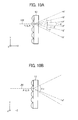
- Figs. 10A and 10B are explanatory diagram of a microlens array (L2) of a second embodiment.
- the microlens array of the second embodiment is the same in shape as the microlens array of the first embodiment and is two-dimensionally scanned with a light flux beam LB2 in X and Y directions.
- optical systems are provided which are similar to the optical systems depicted in Figs. 1A to 1C .
- angles of divergence are desirably ⁇ , ⁇ , and ⁇ ( ⁇ ⁇ ⁇ ⁇ ⁇ ) at the positions P, Q, and R (see Fig. 9A ), respectively.
- the angle of divergence is set to the largest ⁇ of ⁇ , ⁇ and ⁇ .
- the curvature (radius of curvature) of each microlens is set to a value that renders the angle of divergence become ⁇ .
- the desired angle of divergence is attained at each of the positions P, Q, and R.
- the angles of divergence at the positions P and Q are matched to the angle of divergence ⁇ at the position R, the incident light flux is diverged at an angle of divergence that is larger than the originally desired angle of divergence at the positions P and Q. As a result, a portion of the light flux incident on the microlens array is diverged more than expected, inviting lowering of light use efficiency and brightness.
- the angle of divergence of incident light flux is made different depending on in-plane positions on the microlens array.
- Figs. 11A and 11B are explanatory diagrams of a microlens array (L3) of the third embodiment.
- the microlens array of the third embodiment is the same in shape as the microlens arrays of the first and second embodiments and is two-dimensionally scanned (e.g., raster scan) with a light flux beam LB3 in X and Y directions.
- the angles of divergence of the light flux beam LB3 incident on the positions P, Q, and R are set to angles of divergence ⁇ , ⁇ , and ⁇ ( ⁇ ⁇ ⁇ ⁇ ⁇ ) that are desired for each position.
- the desired angles of divergence are determined, for example, according to the optical path lengths between in-plane positions on the microlens array (the microlenses) and the observation location, and the direction in which the incoming laser light from the reflective surface 10 is reflected, i.e., the direction in which the laser light is incident on the observer eye.
- the micro lenses may have a larger mean curvature in the area with the shorter optical path lengths than in the area with the longer optical path lengths.
- the distribution of radii of curvature in the microlens array may be determined accordingly.
- the distribution of curvatures of the microlenses in the microlens array exhibits approximately monotonous decrease from the area occupied by larger curvatures toward the area occupied by smaller curvatures.
- the angle of divergence is set to a minimum value at each in-plane position, such that incident light flux is diverged without loss. This improves light use efficiency and enhances the brightness.
- the microlens array having angles of divergence different by in-plane position as described above is actually fabricable (see, for example, JP-2009-111209-A .)
- the angle of divergence at each in-plane position on the microlens array is controllable by way of the lens pitches in the microlens array and the radius of curvature of each microlens.
- the radii of curvature of a plurality of microlenses may be changed according to the lens pitches so as to establish a positional function of X and Y.
- the radius of curvature of each microlens of the microlens array is set based on the optical path length of laser light between the microlens and the reflective surface 10. Specifically, the radius of curvature of the microlens is set larger, i.e., the curvature is set smaller, as the optical path length of laser light from each microlens to the reflective surface 10 is longer. To put it in an opposite way, the radius of curvature of the microlens is set smaller, i.e., the curvature is set larger, as the optical path length of laser light from each microlens to the reflective surface 10 is shorter. It is to be noted that the curvature of each microlens may be set based on the direction in which the laser light is reflected from the reflective surface 10, instead of or in addition to the above-described optical path length.
- the optical path of laser light has lengths different from each other between a first one of at least two of the entire microlenses and the observation location, and a second one of the at least two of the microlenses and the observation location.
- the optical path of laser light has a uniform length between each one of the microlenses of the microlens array and the observation location.
- the microlens arrays of the present embodiments at least two microlenses have radii of curvature different from each other.
- the microlens arrays have in-plane distribution of radii of curvature.
- modes of distribution of radii of curvature include a mode such as a microlens array of a fourth embodiment depicted in Fig. 12A having a distribution in X direction (the longer-side direction) and not in Y direction (shorter-side direction), and a mode such as a microlens array of a fifth embodiment as depicted in Fig. 12B having a distribution in Y direction (shorter-side direction), and a mode such as a microlens array of a sixth embodiment as depicted in Fig. 12C having distributions of radii of curvature both in X and Y directions.
- Fig. 13 is an explanatory diagram of a case in which the virtual image of an image formed on the microlens array is made visible by a transmission reflection member (e.g., the windshield of a moving body) that is asymmetrical with respect to the vertical plane including the observer eye.
- a transmission reflection member e.g., the windshield of a moving body
- the vertical direction is Y direction
- a direction that is parallel to the horizontal plane and is also parallel to the observer eye is Z direction.
- a portion of the laser light transmitted by the microlens array is reflected by the transmission reflection member in the form of the reflective surface 10, so as to be sent to the position of the observer eye.
- the observer then perceives the image formed on the microlens array as a virtual image.
- the windshield of a vehicle is conceived as the transmission reflection member.
- the observer observes a virtual image at the observation location, which is the position of the driver's seat that is to the right or left with respect to the center of the windshield.
- a vehicle with a right steering wheel is assumed.
- the windshield has a shape asymmetrical with respect to the vertical plane (Y-Z plane) including the observer eye.
- the optical path lengths between each of the microlenses of the microlens array and the windshield have a distribution with respect to X direction. Further, the optical path lengths of laser light from each microlens also have a distribution with respect to X direction between the position of incidence on the windshield and the observer eye.
- optical path lengths are different from each other between two light beams 1 and 2 that are emitted from two ends along X direction of the microlens array, are reflected by the windshield, and reach the observer eye.
- the two light beams 1 and 2 are also different from each other in direction in which the light beams are reflected by the windshield.
- the radii of curvature are desirably distributed along X direction in the microlens array based on the optical path lengths of the two light beams 1 and 2 and the directions in which the light beams are reflected by the windshield, i.e., radii of curvature of at least two microlenses arranged in X direction are defined desirably differently.
- the radii of curvature are desirably distributed along Y direction in the microlens array based on the optical path lengths of the above-described two light beams 1 and 2 and the directions in which the light beams are reflected by the windshield, i.e., radii of curvature of at least two microlenses arranged in Y direction are defined desirably differently.
- the curvatures of a plurality of microlenses are desirably set based on the positional relationship between the microlens array and the transmission reflection member, as well as the positional relationship between a predetermined observation location at which the eye of the observer (e.g., the operator sitting at the operator's seat) is located and the transmission reflection member. This is achieved, for example, by preliminarily setting a spatial domain that is assumed to have the observer eye located therein and defining the set spatial domain as the observation location. Further, for example in Fig.
- the observation location may also be set to a planar domain in which the optical path of laser light reflected by the transmission reflection member crosses a predetermined plane that is parallel to X-Y plane, in which planar domain the observer eye is presumably located. Further, the observation location may be set to a certain point (e.g., the central point) in the spatial domain or the planar domain in which the observer eye is presumably located. It is to be noted however that the above spatial domain and planar domain are desirably set slightly larger considering individual differences such as the physique of the observer or positional change of the head of the observer while observing the virtual image.
- the curvature of each of the plurality of microlenses is desirably set based on the optical path length of laser light between the microlens and the above-described observation location, i.e., the optical path length of laser light reaching the observation location from each microlens through the transmission reflection member.
- the longer the optical path length of laser light between each microlens and the above-described observation location the smaller the curvature of the microlens is set, i.e., the larger the radius of curvature is set, so as to reduce the angle of divergence of the laser light.
- the shorter the optical path length of laser light between each microlens and the above-described observation location the larger the curvature of the microlens is set, i.e., the smaller the radius of curvature is set, so as to enlarge the angle of divergence of the laser light.
- cross-sectional sizes of laser light from each microlens are desirably approximately equalized at the observation location.
- the respective curvatures of the plurality of microlenses may be set based on the result of measurement obtained by actually measuring the optical path length of laser light between the microlens and the above-mentioned predetermined position by using, for example, a laser length measuring machine.
- optical path length of laser light between each microlens and the transmission reflection member is determined depending on the positional relationship between the microlens array and the transmission reflection member. Further, the optical path length of laser light transmitted by each microlens between the transmission reflection member and the above-described observation location is determined depending on the positional relationship between the above-described observation location and the transmission reflection member.
- each microlens may be set based on the direction of reflection of the laser light that is transmitted by the microlens and is reflected by the transmission reflection member, i.e., the direction in which the principal beam of the reflected light proceeds.
- the curvatures of the microlenses may be set smaller and the angles of divergence may be set smaller as the direction of reflection of laser light is such a direction that the laser light is incident on the observer eye, who is straightly looking at the windshield, at a larger incidence angle (e.g., an angle formed with the gaze of the observer.)
- a larger incidence angle e.g., an angle formed with the gaze of the observer.
- the cross section of light incident on the observer eye is larger as the incidence angle of the laser light on the observer eye is larger.
- the direction in which laser light is reflected from the transmission reflection member is found based on the direction in which the laser light is incident on the transmission reflection member.
- the directions in which light is emitted from the microlenses i.e., the optical axes of the microlenses
- the directions in which light is emitted from at least two microlenses may be set non-parallel. It is to be noted that adjustment of orientations of the optical axes of the microlenses allows for adjustment of the optical path lengths and directions of reflection of the laser light that is transmitted by the microlenses and is reflected by the transmission reflection member.
- the curvatures of the microlenses of the microlens array may be entirely different from each other; alternatively, the curvatures of a portion of the microlenses may be different, and the curvatures of the remaining microlenses may be the same. In short, the curvatures of at least two microlenses are different.
- the curvatures of a plurality of microlenses including the microlens array are two kinds or more, and the curvatures are distributed within the plane of the microlens array based on the layout of the optical systems and the observation location. In this manner, the angles of divergence at in-plane positions are set minimum.
- a plurality of microlenses is two-dimensionally arranged.
- the microlenses may be one-dimensionally arranged or three-dimensionally arranged.
- the microlens arrays are two-dimensionally scanned by using the two-dimensional deflector to form a two-dimensional image; however, the microlens array may be one-dimensionally scanned by using, for example, a one-dimensional deflector including an MEMS mirror, a galvanometer-driven mirror, and a polygon mirror to form a one-dimensional image.
- a one-dimensional deflector including an MEMS mirror, a galvanometer-driven mirror, and a polygon mirror to form a one-dimensional image.
- color images are formed, but monochrome images may be formed as well.
- the transmission reflection member in the form of the reflective surface 10 may, for example, include a member other than the windshield of a moving body, like a combiner, and may be located at the observer's side from the windshield.
- the transmission reflection member is not limited to the windshield of a moving body and may also be, for example, a side glass or a rear glass.
- the transmission reflection member may be a window member that is disposed in a moving body to be operated by an operator who sees the virtual image, and that allows the operator to see the outside of the moving body.
- the target audience to whom the virtual image is made visible by the image display apparatus is not limited to the operator of a moving body and may also be, for example, a navigator or a passenger boarding the moving body.
- the image display apparatus of any of the present embodiments described above scans a microlens array including a plurality of microlenses with laser light that is modulated in accordance with image information so as to form an image.
- the image display apparatus allows the laser light transmitted by the microlens array to be incident on a transmission reflection member, such that a virtual image of the image is visualized at an observation location on the optical path of the laser light reflected by the transmission reflection member.
- the curvature of each of the plurality of microlenses is set based on the optical path length of the laser light between the microlens and the observation location.
- the curvature of each of the plurality of microlenses may be set such that the angle of divergence of the laser light from the microlens takes an appropriate value adjusted to the optical length.
- the radius of curvature of each microlens of isotropic diffusion type may be set based on the optical path length of laser light between the microlens and the observation location.
- the radii of curvature of the microlenses may be adjusted in X and Y directions at mutually equal magnifications like the microlenses of isotropic diffusion type; alternatively, the adjustment may be performed at magnifications not equal to each other.
- At least one of the curvatures of each of the plurality of microlenses in first and second directions orthogonal to each other may be set based on the optical path length of laser light between the microlens and the above-described observation location.
- an appropriate value that is adjusted to the optical path length of laser light between each microlens and the observation location may be adopted for setting at least one of the angles of divergence of the laser light with respect to the first and second directions (e.g., X and Y directions), the divergence being caused by of the microlens.
- the first and second directions e.g., X and Y directions
- This setting is effective in case where different angles of divergence are desired for the angle of divergence with respect to each of the first and second directions (e.g., X and Y directions), or in case of a design concept in which the radii of curvature are different from each other with respect to the first and second directions of each microlens in the microlens array (in case where the microlenses are of anisotropic diffusion type.)
- At least one of the curvatures with respect to the above-described first and second directions may be set based on the direction of reflection of laser light that is transmitted by the microlens and is reflected by the transmission reflection member.
- the image display apparatus is applicable to, for example, a head-mount display mountable to the head of the observer.
- the present invention may reside in an image display apparatus configured such that a microlens array including a plurality of microlenses is irradiated with laser light to form an image, the laser light being modulated in accordance with image information, and that a transmission reflection member allows the laser light transmitted by the microlens array to be incident thereon, in such a manner as to visualize a virtual image of the image at an observation location on an optical path of the laser light reflected by the transmission reflection member.
- At least one of curvatures of each of the plurality of microlenses in a first direction and a second direction is set based on a length of the optical path of the laser light between the microlens and the observation location, the first and second directions being orthogonal to each other.
- the lengths of the optical paths of the laser light are different from each other between each of at least two microlenses of the plurality of microlenses and the observation location.
Priority Applications (1)
| Application Number | Priority Date | Filing Date | Title |
|---|---|---|---|
| EP18151486.0A EP3346303A1 (fr) | 2014-02-03 | 2015-01-26 | Appareil d'affichage d'images avec réseau de micro-lentilles ayant des lentilles de courbures différentes |
Applications Claiming Priority (1)
| Application Number | Priority Date | Filing Date | Title |
|---|---|---|---|
| JP2014018686A JP6315240B2 (ja) | 2014-02-03 | 2014-02-03 | 画像表示装置、移動体及びレンズアレイ |
Related Child Applications (2)
| Application Number | Title | Priority Date | Filing Date |
|---|---|---|---|
| EP18151486.0A Division-Into EP3346303A1 (fr) | 2014-02-03 | 2015-01-26 | Appareil d'affichage d'images avec réseau de micro-lentilles ayant des lentilles de courbures différentes |
| EP18151486.0A Division EP3346303A1 (fr) | 2014-02-03 | 2015-01-26 | Appareil d'affichage d'images avec réseau de micro-lentilles ayant des lentilles de courbures différentes |
Publications (2)
| Publication Number | Publication Date |
|---|---|
| EP2902819A1 true EP2902819A1 (fr) | 2015-08-05 |
| EP2902819B1 EP2902819B1 (fr) | 2018-03-07 |
Family
ID=52432671
Family Applications (2)
| Application Number | Title | Priority Date | Filing Date |
|---|---|---|---|
| EP18151486.0A Withdrawn EP3346303A1 (fr) | 2014-02-03 | 2015-01-26 | Appareil d'affichage d'images avec réseau de micro-lentilles ayant des lentilles de courbures différentes |
| EP15152533.4A Not-in-force EP2902819B1 (fr) | 2014-02-03 | 2015-01-26 | Afficheur d'images muni d'un réseau de lentilles ayant des lentilles de courbures différentes |
Family Applications Before (1)
| Application Number | Title | Priority Date | Filing Date |
|---|---|---|---|
| EP18151486.0A Withdrawn EP3346303A1 (fr) | 2014-02-03 | 2015-01-26 | Appareil d'affichage d'images avec réseau de micro-lentilles ayant des lentilles de courbures différentes |
Country Status (3)
| Country | Link |
|---|---|
| US (1) | US11002887B2 (fr) |
| EP (2) | EP3346303A1 (fr) |
| JP (1) | JP6315240B2 (fr) |
Families Citing this family (30)
| Publication number | Priority date | Publication date | Assignee | Title |
|---|---|---|---|---|
| JP6340807B2 (ja) * | 2014-02-05 | 2018-06-13 | 株式会社リコー | 画像表示装置及び移動体 |
| JPWO2016079927A1 (ja) * | 2014-11-19 | 2017-09-07 | パナソニックIpマネジメント株式会社 | ヘッドアップディスプレイ及び車両 |
| CN107209449B (zh) | 2015-02-04 | 2020-03-06 | 大日本印刷株式会社 | 透射型屏幕和使用该透射型屏幕的平视显示器装置 |
| JP6617945B2 (ja) | 2015-03-11 | 2019-12-11 | 株式会社リコー | 画像表示装置 |
| JP6551730B2 (ja) | 2015-04-28 | 2019-07-31 | 株式会社リコー | 画像表示装置及び移動体 |
| JP6504353B2 (ja) | 2015-04-28 | 2019-04-24 | 株式会社リコー | 画像表示装置及び物体装置 |
| JP6726674B2 (ja) * | 2015-10-15 | 2020-07-22 | マクセル株式会社 | 情報表示装置 |
| US10656415B2 (en) * | 2015-12-01 | 2020-05-19 | Panasonic Intellectual Property Management Co., Ltd. | Head-up display, and mobile object equipped with head-up display |
| WO2017138292A1 (fr) | 2016-02-09 | 2017-08-17 | 株式会社リコー | Appareil d'affichage d'images et procédé d'affichage d'images |
| CN108700750B (zh) * | 2016-08-31 | 2021-09-28 | 松下知识产权经营株式会社 | 显示装置 |
| EP3518022A4 (fr) * | 2016-09-21 | 2020-05-06 | Nippon Seiki Co., Ltd. | Dispositif d'affichage d'image virtuelle |
| JP6695043B2 (ja) * | 2016-11-11 | 2020-05-20 | パナソニックIpマネジメント株式会社 | 画像表示装置およびスクリーン |
| DE102016224162A1 (de) * | 2016-12-05 | 2018-06-07 | Continental Automotive Gmbh | Head-Up-Display |
| JP7027856B2 (ja) * | 2017-02-21 | 2022-03-02 | 株式会社リコー | 表示装置及び機器 |
| EP3370103A1 (fr) | 2017-03-02 | 2018-09-05 | Ricoh Company Ltd. | Dispositif d'affichage et appareil |
| JP2018156062A (ja) | 2017-03-15 | 2018-10-04 | 株式会社リコー | 表示装置、物体装置及び表示方法 |
| EP3376280B1 (fr) | 2017-03-15 | 2023-04-05 | Ricoh Company, Ltd. | Dispositif d'affichage et appareil |
| JP7091667B2 (ja) | 2017-03-17 | 2022-06-28 | 株式会社リコー | 表示装置、物体装置、画像形成ユニット及び表示方法 |
| JP6535702B2 (ja) | 2017-06-13 | 2019-06-26 | 浜松ホトニクス株式会社 | 走査型表示装置及び走査型表示システム |
| US11067800B2 (en) * | 2017-10-04 | 2021-07-20 | Samsung Electronics Co., Ltd. | Image display device |
| JP7204317B2 (ja) * | 2017-10-04 | 2023-01-16 | 三星電子株式会社 | 画像表示装置 |
| US11378800B2 (en) | 2018-01-11 | 2022-07-05 | Samsung Electronics Co., Ltd. | Image display apparatus |
| JP2019158991A (ja) | 2018-03-09 | 2019-09-19 | 株式会社リコー | 表示装置、表示システムおよび移動体 |
| JP7102797B2 (ja) * | 2018-03-12 | 2022-07-20 | 株式会社リコー | 光学装置、これを用いた距離計測装置、及び移動体 |
| JP2019164239A (ja) | 2018-03-19 | 2019-09-26 | 株式会社リコー | 表示装置及び機器 |
| CN112074770B (zh) * | 2018-05-04 | 2023-08-22 | 哈曼国际工业有限公司 | 可调整的三维增强现实平视显示器 |
| JP2019200224A (ja) | 2018-05-14 | 2019-11-21 | 株式会社リコー | 光学素子、表示システムおよび移動体 |
| EP3712684A1 (fr) | 2019-03-18 | 2020-09-23 | Ricoh Company, Ltd. | Système d'affichage, objet mobile et élément optique |
| JP2021039300A (ja) * | 2019-09-05 | 2021-03-11 | 矢崎総業株式会社 | 車両用表示装置 |
| JP7098594B2 (ja) * | 2019-10-23 | 2022-07-11 | 浜松ホトニクス株式会社 | 走査型表示装置及び走査型表示システム |
Citations (7)
| Publication number | Priority date | Publication date | Assignee | Title |
|---|---|---|---|---|
| JPH0510445B2 (fr) | 1985-05-23 | 1993-02-09 | Tokyu Kensetsu Kk | |
| JP2000155201A (ja) * | 1998-11-19 | 2000-06-06 | Omron Corp | レンズアレイ基板、その製造方法及び反射型画像表示装置 |
| JP4200223B2 (ja) | 2005-08-19 | 2008-12-24 | 国立大学法人 香川大学 | マイクロレンズ用金型、マイクロレンズおよびそれらの製法 |
| JP2009111209A (ja) | 2007-10-31 | 2009-05-21 | Dainippon Printing Co Ltd | 固体撮像素子およびそれを用いた撮像装置 |
| US20120154920A1 (en) * | 2010-12-16 | 2012-06-21 | Lockheed Martin Corporation | Collimating display with pixel lenses |
| JP2013254031A (ja) | 2012-06-05 | 2013-12-19 | Denso Corp | ヘッドアップディスプレイ装置 |
| EP2746825A1 (fr) * | 2012-12-21 | 2014-06-25 | Ricoh Company Ltd. | Dispositif d'affichage d'image et véhicule l'incorporant |
Family Cites Families (12)
| Publication number | Priority date | Publication date | Assignee | Title |
|---|---|---|---|---|
| JP3346629B2 (ja) | 1993-11-26 | 2002-11-18 | オリンパス光学工業株式会社 | 焦点板および焦点板成形用型の製造方法 |
| JP4268399B2 (ja) * | 2002-11-01 | 2009-05-27 | パイオニア株式会社 | 画像表示装置 |
| JP2005070631A (ja) | 2003-08-27 | 2005-03-17 | Seiko Epson Corp | スクリーン及びプロジェクタ |
| JP2007523369A (ja) * | 2004-02-04 | 2007-08-16 | マイクロビジョン,インク. | 走査ビームヘッドアップ表示装置および関連システム、および方法 |
| US7339737B2 (en) | 2004-04-23 | 2008-03-04 | Microvision, Inc. | Beam multiplier that can be used as an exit-pupil expander and related system and method |
| US7414790B2 (en) * | 2006-11-10 | 2008-08-19 | Genie Lens Technologies, Llc | Ultrathin lens arrays for viewing interlaced images with dual lens structures |
| JP5010445B2 (ja) | 2007-11-29 | 2012-08-29 | パナソニック株式会社 | マイクロレンズアレイ用金型の製造方法 |
| JP2010145745A (ja) * | 2008-12-18 | 2010-07-01 | Equos Research Co Ltd | 画像形成装置、及び、ヘッドアップディスプレイ装置 |
| JP2010211065A (ja) * | 2009-03-11 | 2010-09-24 | Denso Corp | 表示装置 |
| JP5333943B2 (ja) * | 2010-03-04 | 2013-11-06 | 日本精機株式会社 | 表示装置 |
| JPWO2013153655A1 (ja) * | 2012-04-12 | 2015-12-17 | パイオニア株式会社 | 光学素子、ヘッドアップディスプレイ及び光源ユニット |
| FR3000572B1 (fr) * | 2012-12-28 | 2016-04-29 | Valeo Etudes Electroniques | Dispositif de transmission d'images pour afficheur et afficheur tete haute equipe dudit dispositif |
-
2014
- 2014-02-03 JP JP2014018686A patent/JP6315240B2/ja active Active
-
2015
- 2015-01-23 US US14/603,757 patent/US11002887B2/en active Active
- 2015-01-26 EP EP18151486.0A patent/EP3346303A1/fr not_active Withdrawn
- 2015-01-26 EP EP15152533.4A patent/EP2902819B1/fr not_active Not-in-force
Patent Citations (7)
| Publication number | Priority date | Publication date | Assignee | Title |
|---|---|---|---|---|
| JPH0510445B2 (fr) | 1985-05-23 | 1993-02-09 | Tokyu Kensetsu Kk | |
| JP2000155201A (ja) * | 1998-11-19 | 2000-06-06 | Omron Corp | レンズアレイ基板、その製造方法及び反射型画像表示装置 |
| JP4200223B2 (ja) | 2005-08-19 | 2008-12-24 | 国立大学法人 香川大学 | マイクロレンズ用金型、マイクロレンズおよびそれらの製法 |
| JP2009111209A (ja) | 2007-10-31 | 2009-05-21 | Dainippon Printing Co Ltd | 固体撮像素子およびそれを用いた撮像装置 |
| US20120154920A1 (en) * | 2010-12-16 | 2012-06-21 | Lockheed Martin Corporation | Collimating display with pixel lenses |
| JP2013254031A (ja) | 2012-06-05 | 2013-12-19 | Denso Corp | ヘッドアップディスプレイ装置 |
| EP2746825A1 (fr) * | 2012-12-21 | 2014-06-25 | Ricoh Company Ltd. | Dispositif d'affichage d'image et véhicule l'incorporant |
Also Published As
| Publication number | Publication date |
|---|---|
| JP2015145962A (ja) | 2015-08-13 |
| US20150219803A1 (en) | 2015-08-06 |
| US11002887B2 (en) | 2021-05-11 |
| EP2902819B1 (fr) | 2018-03-07 |
| JP6315240B2 (ja) | 2018-04-25 |
| EP3346303A1 (fr) | 2018-07-11 |
Similar Documents
| Publication | Publication Date | Title |
|---|---|---|
| EP2902819B1 (fr) | Afficheur d'images muni d'un réseau de lentilles ayant des lentilles de courbures différentes | |
| EP2916149B1 (fr) | Réseau de lentilles, appareil d'affichage d'image et corps mobile | |
| JP6753490B2 (ja) | 画像表示装置および移動体 | |
| US10502972B2 (en) | Image display device and mobile object | |
| JP6237124B2 (ja) | 2次元画像表示装置および2次元画像表示装置用の光走査装置および被走査面素子および移動体 | |
| JP5682692B2 (ja) | 画像表示装置 | |
| JP6555507B2 (ja) | 画像表示装置及び移動体 | |
| JP6579485B2 (ja) | 光走査装置、画像表示装置及び物体装置 | |
| EP2746825A1 (fr) | Dispositif d'affichage d'image et véhicule l'incorporant | |
| JP6638198B2 (ja) | 画像表示装置及び移動体 | |
| JP6645567B2 (ja) | 画像表示装置及び移動体及び被走査面素子 | |
| JP2020149032A (ja) | 光学素子、表示装置、表示システムおよび移動体 | |
| JP6651139B2 (ja) | 画像表示装置及び移動体 | |
| JP2018200489A (ja) | レンズアレイ、画像表示装置、及び移動体 | |
| JP2018136558A (ja) | 画像表示装置及び移動体 | |
| JP2020074025A (ja) | 画像表示装置及び移動体 |
Legal Events
| Date | Code | Title | Description |
|---|---|---|---|
| PUAI | Public reference made under article 153(3) epc to a published international application that has entered the european phase |
Free format text: ORIGINAL CODE: 0009012 |
|
| 17P | Request for examination filed |
Effective date: 20150126 |
|
| AK | Designated contracting states |
Kind code of ref document: A1 Designated state(s): AL AT BE BG CH CY CZ DE DK EE ES FI FR GB GR HR HU IE IS IT LI LT LU LV MC MK MT NL NO PL PT RO RS SE SI SK SM TR |
|
| AX | Request for extension of the european patent |
Extension state: BA ME |
|
| GRAP | Despatch of communication of intention to grant a patent |
Free format text: ORIGINAL CODE: EPIDOSNIGR1 |
|
| STAA | Information on the status of an ep patent application or granted ep patent |
Free format text: STATUS: GRANT OF PATENT IS INTENDED |
|
| RIC1 | Information provided on ipc code assigned before grant |
Ipc: G02B 3/00 20060101AFI20170804BHEP Ipc: G02B 27/01 20060101ALI20170804BHEP |
|
| INTG | Intention to grant announced |
Effective date: 20170822 |
|
| GRAS | Grant fee paid |
Free format text: ORIGINAL CODE: EPIDOSNIGR3 |
|
| GRAA | (expected) grant |
Free format text: ORIGINAL CODE: 0009210 |
|
| STAA | Information on the status of an ep patent application or granted ep patent |
Free format text: STATUS: THE PATENT HAS BEEN GRANTED |
|
| AK | Designated contracting states |
Kind code of ref document: B1 Designated state(s): AL AT BE BG CH CY CZ DE DK EE ES FI FR GB GR HR HU IE IS IT LI LT LU LV MC MK MT NL NO PL PT RO RS SE SI SK SM TR |
|
| REG | Reference to a national code |
Ref country code: GB Ref legal event code: FG4D |
|
| REG | Reference to a national code |
Ref country code: AT Ref legal event code: REF Ref document number: 977162 Country of ref document: AT Kind code of ref document: T Effective date: 20180315 Ref country code: CH Ref legal event code: EP |
|
| REG | Reference to a national code |
Ref country code: DE Ref legal event code: R096 Ref document number: 602015008501 Country of ref document: DE |
|
| REG | Reference to a national code |
Ref country code: IE Ref legal event code: FG4D |
|
| REG | Reference to a national code |
Ref country code: NL Ref legal event code: MP Effective date: 20180307 |
|
| REG | Reference to a national code |
Ref country code: LT Ref legal event code: MG4D |
|
| PG25 | Lapsed in a contracting state [announced via postgrant information from national office to epo] |
Ref country code: HR Free format text: LAPSE BECAUSE OF FAILURE TO SUBMIT A TRANSLATION OF THE DESCRIPTION OR TO PAY THE FEE WITHIN THE PRESCRIBED TIME-LIMIT Effective date: 20180307 Ref country code: LT Free format text: LAPSE BECAUSE OF FAILURE TO SUBMIT A TRANSLATION OF THE DESCRIPTION OR TO PAY THE FEE WITHIN THE PRESCRIBED TIME-LIMIT Effective date: 20180307 Ref country code: FI Free format text: LAPSE BECAUSE OF FAILURE TO SUBMIT A TRANSLATION OF THE DESCRIPTION OR TO PAY THE FEE WITHIN THE PRESCRIBED TIME-LIMIT Effective date: 20180307 Ref country code: NO Free format text: LAPSE BECAUSE OF FAILURE TO SUBMIT A TRANSLATION OF THE DESCRIPTION OR TO PAY THE FEE WITHIN THE PRESCRIBED TIME-LIMIT Effective date: 20180607 Ref country code: CY Free format text: LAPSE BECAUSE OF FAILURE TO SUBMIT A TRANSLATION OF THE DESCRIPTION OR TO PAY THE FEE WITHIN THE PRESCRIBED TIME-LIMIT Effective date: 20180307 Ref country code: ES Free format text: LAPSE BECAUSE OF FAILURE TO SUBMIT A TRANSLATION OF THE DESCRIPTION OR TO PAY THE FEE WITHIN THE PRESCRIBED TIME-LIMIT Effective date: 20180307 |
|
| REG | Reference to a national code |
Ref country code: AT Ref legal event code: MK05 Ref document number: 977162 Country of ref document: AT Kind code of ref document: T Effective date: 20180307 |
|
| PG25 | Lapsed in a contracting state [announced via postgrant information from national office to epo] |
Ref country code: GR Free format text: LAPSE BECAUSE OF FAILURE TO SUBMIT A TRANSLATION OF THE DESCRIPTION OR TO PAY THE FEE WITHIN THE PRESCRIBED TIME-LIMIT Effective date: 20180608 Ref country code: SE Free format text: LAPSE BECAUSE OF FAILURE TO SUBMIT A TRANSLATION OF THE DESCRIPTION OR TO PAY THE FEE WITHIN THE PRESCRIBED TIME-LIMIT Effective date: 20180307 Ref country code: LV Free format text: LAPSE BECAUSE OF FAILURE TO SUBMIT A TRANSLATION OF THE DESCRIPTION OR TO PAY THE FEE WITHIN THE PRESCRIBED TIME-LIMIT Effective date: 20180307 Ref country code: RS Free format text: LAPSE BECAUSE OF FAILURE TO SUBMIT A TRANSLATION OF THE DESCRIPTION OR TO PAY THE FEE WITHIN THE PRESCRIBED TIME-LIMIT Effective date: 20180307 Ref country code: BG Free format text: LAPSE BECAUSE OF FAILURE TO SUBMIT A TRANSLATION OF THE DESCRIPTION OR TO PAY THE FEE WITHIN THE PRESCRIBED TIME-LIMIT Effective date: 20180607 |
|
| PG25 | Lapsed in a contracting state [announced via postgrant information from national office to epo] |
Ref country code: EE Free format text: LAPSE BECAUSE OF FAILURE TO SUBMIT A TRANSLATION OF THE DESCRIPTION OR TO PAY THE FEE WITHIN THE PRESCRIBED TIME-LIMIT Effective date: 20180307 Ref country code: AL Free format text: LAPSE BECAUSE OF FAILURE TO SUBMIT A TRANSLATION OF THE DESCRIPTION OR TO PAY THE FEE WITHIN THE PRESCRIBED TIME-LIMIT Effective date: 20180307 Ref country code: NL Free format text: LAPSE BECAUSE OF FAILURE TO SUBMIT A TRANSLATION OF THE DESCRIPTION OR TO PAY THE FEE WITHIN THE PRESCRIBED TIME-LIMIT Effective date: 20180307 Ref country code: PL Free format text: LAPSE BECAUSE OF FAILURE TO SUBMIT A TRANSLATION OF THE DESCRIPTION OR TO PAY THE FEE WITHIN THE PRESCRIBED TIME-LIMIT Effective date: 20180307 Ref country code: RO Free format text: LAPSE BECAUSE OF FAILURE TO SUBMIT A TRANSLATION OF THE DESCRIPTION OR TO PAY THE FEE WITHIN THE PRESCRIBED TIME-LIMIT Effective date: 20180307 |
|
| PG25 | Lapsed in a contracting state [announced via postgrant information from national office to epo] |
Ref country code: SK Free format text: LAPSE BECAUSE OF FAILURE TO SUBMIT A TRANSLATION OF THE DESCRIPTION OR TO PAY THE FEE WITHIN THE PRESCRIBED TIME-LIMIT Effective date: 20180307 Ref country code: CZ Free format text: LAPSE BECAUSE OF FAILURE TO SUBMIT A TRANSLATION OF THE DESCRIPTION OR TO PAY THE FEE WITHIN THE PRESCRIBED TIME-LIMIT Effective date: 20180307 Ref country code: SM Free format text: LAPSE BECAUSE OF FAILURE TO SUBMIT A TRANSLATION OF THE DESCRIPTION OR TO PAY THE FEE WITHIN THE PRESCRIBED TIME-LIMIT Effective date: 20180307 Ref country code: AT Free format text: LAPSE BECAUSE OF FAILURE TO SUBMIT A TRANSLATION OF THE DESCRIPTION OR TO PAY THE FEE WITHIN THE PRESCRIBED TIME-LIMIT Effective date: 20180307 |
|
| REG | Reference to a national code |
Ref country code: DE Ref legal event code: R097 Ref document number: 602015008501 Country of ref document: DE |
|
| PG25 | Lapsed in a contracting state [announced via postgrant information from national office to epo] |
Ref country code: PT Free format text: LAPSE BECAUSE OF FAILURE TO SUBMIT A TRANSLATION OF THE DESCRIPTION OR TO PAY THE FEE WITHIN THE PRESCRIBED TIME-LIMIT Effective date: 20180709 |
|
| PLBE | No opposition filed within time limit |
Free format text: ORIGINAL CODE: 0009261 |
|
| STAA | Information on the status of an ep patent application or granted ep patent |
Free format text: STATUS: NO OPPOSITION FILED WITHIN TIME LIMIT |
|
| PG25 | Lapsed in a contracting state [announced via postgrant information from national office to epo] |
Ref country code: DK Free format text: LAPSE BECAUSE OF FAILURE TO SUBMIT A TRANSLATION OF THE DESCRIPTION OR TO PAY THE FEE WITHIN THE PRESCRIBED TIME-LIMIT Effective date: 20180307 |
|
| 26N | No opposition filed |
Effective date: 20181210 |
|
| PG25 | Lapsed in a contracting state [announced via postgrant information from national office to epo] |
Ref country code: SI Free format text: LAPSE BECAUSE OF FAILURE TO SUBMIT A TRANSLATION OF THE DESCRIPTION OR TO PAY THE FEE WITHIN THE PRESCRIBED TIME-LIMIT Effective date: 20180307 |
|
| PG25 | Lapsed in a contracting state [announced via postgrant information from national office to epo] |
Ref country code: MC Free format text: LAPSE BECAUSE OF FAILURE TO SUBMIT A TRANSLATION OF THE DESCRIPTION OR TO PAY THE FEE WITHIN THE PRESCRIBED TIME-LIMIT Effective date: 20180307 |
|
| REG | Reference to a national code |
Ref country code: CH Ref legal event code: PL |
|
| PG25 | Lapsed in a contracting state [announced via postgrant information from national office to epo] |
Ref country code: LU Free format text: LAPSE BECAUSE OF NON-PAYMENT OF DUE FEES Effective date: 20190126 |
|
| REG | Reference to a national code |
Ref country code: BE Ref legal event code: MM Effective date: 20190131 |
|
| REG | Reference to a national code |
Ref country code: IE Ref legal event code: MM4A |
|
| PG25 | Lapsed in a contracting state [announced via postgrant information from national office to epo] |
Ref country code: BE Free format text: LAPSE BECAUSE OF NON-PAYMENT OF DUE FEES Effective date: 20190131 |
|
| PG25 | Lapsed in a contracting state [announced via postgrant information from national office to epo] |
Ref country code: LI Free format text: LAPSE BECAUSE OF NON-PAYMENT OF DUE FEES Effective date: 20190131 Ref country code: CH Free format text: LAPSE BECAUSE OF NON-PAYMENT OF DUE FEES Effective date: 20190131 |
|
| PG25 | Lapsed in a contracting state [announced via postgrant information from national office to epo] |
Ref country code: IE Free format text: LAPSE BECAUSE OF NON-PAYMENT OF DUE FEES Effective date: 20190126 |
|
| PG25 | Lapsed in a contracting state [announced via postgrant information from national office to epo] |
Ref country code: TR Free format text: LAPSE BECAUSE OF FAILURE TO SUBMIT A TRANSLATION OF THE DESCRIPTION OR TO PAY THE FEE WITHIN THE PRESCRIBED TIME-LIMIT Effective date: 20180307 |
|
| PGFP | Annual fee paid to national office [announced via postgrant information from national office to epo] |
Ref country code: GB Payment date: 20200124 Year of fee payment: 6 Ref country code: DE Payment date: 20200121 Year of fee payment: 6 Ref country code: IT Payment date: 20200131 Year of fee payment: 6 |
|
| PG25 | Lapsed in a contracting state [announced via postgrant information from national office to epo] |
Ref country code: MT Free format text: LAPSE BECAUSE OF NON-PAYMENT OF DUE FEES Effective date: 20190126 |
|
| PGFP | Annual fee paid to national office [announced via postgrant information from national office to epo] |
Ref country code: FR Payment date: 20200121 Year of fee payment: 6 |
|
| PG25 | Lapsed in a contracting state [announced via postgrant information from national office to epo] |
Ref country code: IS Free format text: LAPSE BECAUSE OF FAILURE TO SUBMIT A TRANSLATION OF THE DESCRIPTION OR TO PAY THE FEE WITHIN THE PRESCRIBED TIME-LIMIT Effective date: 20180707 |
|
| PG25 | Lapsed in a contracting state [announced via postgrant information from national office to epo] |
Ref country code: HU Free format text: LAPSE BECAUSE OF FAILURE TO SUBMIT A TRANSLATION OF THE DESCRIPTION OR TO PAY THE FEE WITHIN THE PRESCRIBED TIME-LIMIT; INVALID AB INITIO Effective date: 20150126 |
|
| REG | Reference to a national code |
Ref country code: DE Ref legal event code: R119 Ref document number: 602015008501 Country of ref document: DE |
|
| GBPC | Gb: european patent ceased through non-payment of renewal fee |
Effective date: 20210126 |
|
| PG25 | Lapsed in a contracting state [announced via postgrant information from national office to epo] |
Ref country code: FR Free format text: LAPSE BECAUSE OF NON-PAYMENT OF DUE FEES Effective date: 20210131 |
|
| PG25 | Lapsed in a contracting state [announced via postgrant information from national office to epo] |
Ref country code: DE Free format text: LAPSE BECAUSE OF NON-PAYMENT OF DUE FEES Effective date: 20210803 Ref country code: GB Free format text: LAPSE BECAUSE OF NON-PAYMENT OF DUE FEES Effective date: 20210126 |
|
| PG25 | Lapsed in a contracting state [announced via postgrant information from national office to epo] |
Ref country code: IT Free format text: LAPSE BECAUSE OF NON-PAYMENT OF DUE FEES Effective date: 20210126 |
|
| PG25 | Lapsed in a contracting state [announced via postgrant information from national office to epo] |
Ref country code: MK Free format text: LAPSE BECAUSE OF FAILURE TO SUBMIT A TRANSLATION OF THE DESCRIPTION OR TO PAY THE FEE WITHIN THE PRESCRIBED TIME-LIMIT Effective date: 20180307 |